1.52M WOODWORKING BENCH
MODEL NO: AP1520.V2
Thank you for purchasing a Sealey product. Manufactured to a high standard, this product will, if used according to these
instructions, and properly maintained, give you years of trouble free performance.
IMPORTANT: PLEASE READ THESE INSTRUCTIONS CAREFULLY. NOTE THE SAFE OPERATIONAL REQUIREMENTS, WARNINGS & CAUTIONS. USE
THE PRODUCT CORRECTLY AND WITH CARE FOR THE PURPOSE FOR WHICH IT IS INTENDED. FAILURE TO DO SO MAY CAUSE DAMAGE AND/OR
PERSONAL INJURY AND WILL INVALIDATE THE WARRANTY. KEEP THESE INSTRUCTIONS SAFE FOR FUTURE USE.
1. SAFETY
1.1. GENERAL SAFETY
WARNING! Ensure Health & Safety, local authority, and general workshop
practice regulations are adhered to when using this bench.
9 Locate the bench in a suitable work area.
9 Keep the work area clean, uncluttered and ensure there is adequate lighting.
WARNING! Use the bench on level and solid ground, preferably concrete.
9 Keep the bench clean and tidy in accordance with good workshop practice.
9 Keep children and unauthorised persons away from the work area.
8 DO NOT use the bench for any purpose other than for which it is designed.
8 DO NOT undertake work on the bench without the workpiece being
adequately secured
8 DO NOT use the bench outdoors.
8 DO NOT get the bench wet or use in damp or wet locations or areas where
there is condensation.
8 DO NOT clean the bench with any solvents which may damage the surface or the protective coating on the worktop.
2. INTRODUCTION
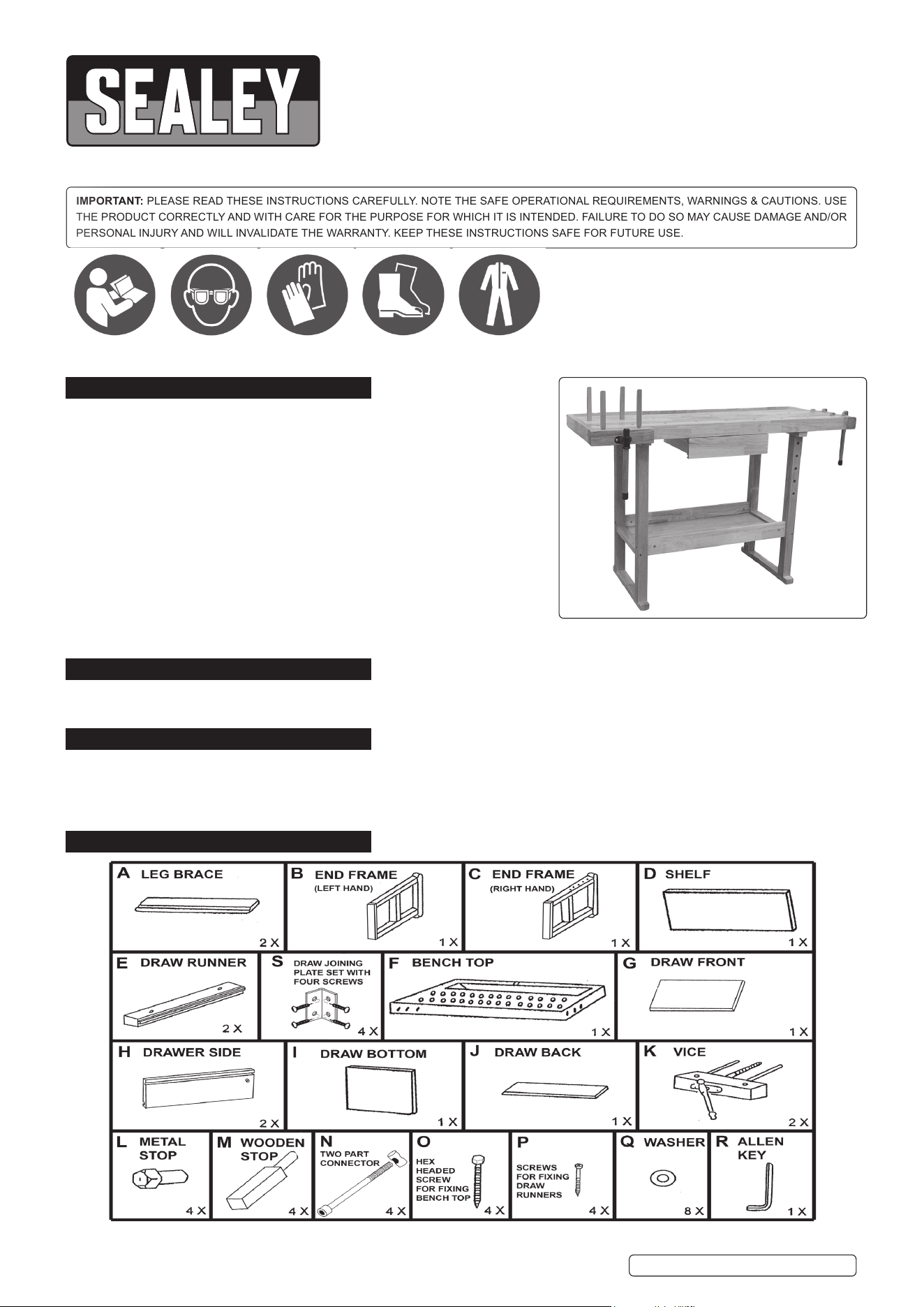
Made from oak with a varnished nish. Features tool well, shelf, tool drawer, front and end vices, four metal bench stops and four wooden
board jacks.
3. SPECIFICATION
Model No: ............................................................ AP1520.V2
Size(W x D x H): ...................................1520 x 620 x 850mm
Vice dimensions (x2): .......... 280mm Wide x 190mm Opening
Worktop (W x D): ............................................1390 x 355mm
4. CONTENTS
AP1520.V2 Issue 1 23/04/21
Original Language Version
© Jack Sealey Limited
Refer to
instructions
Wear eye
protection
Wear protective
gloves
Wear safety
footwear
Wear protective
clothing
5. ASSEMBLY
Unpack the product and check contents against the attached contents diagram prior to assembly. Should there be any damaged or
missing parts contact you supplier immediately.
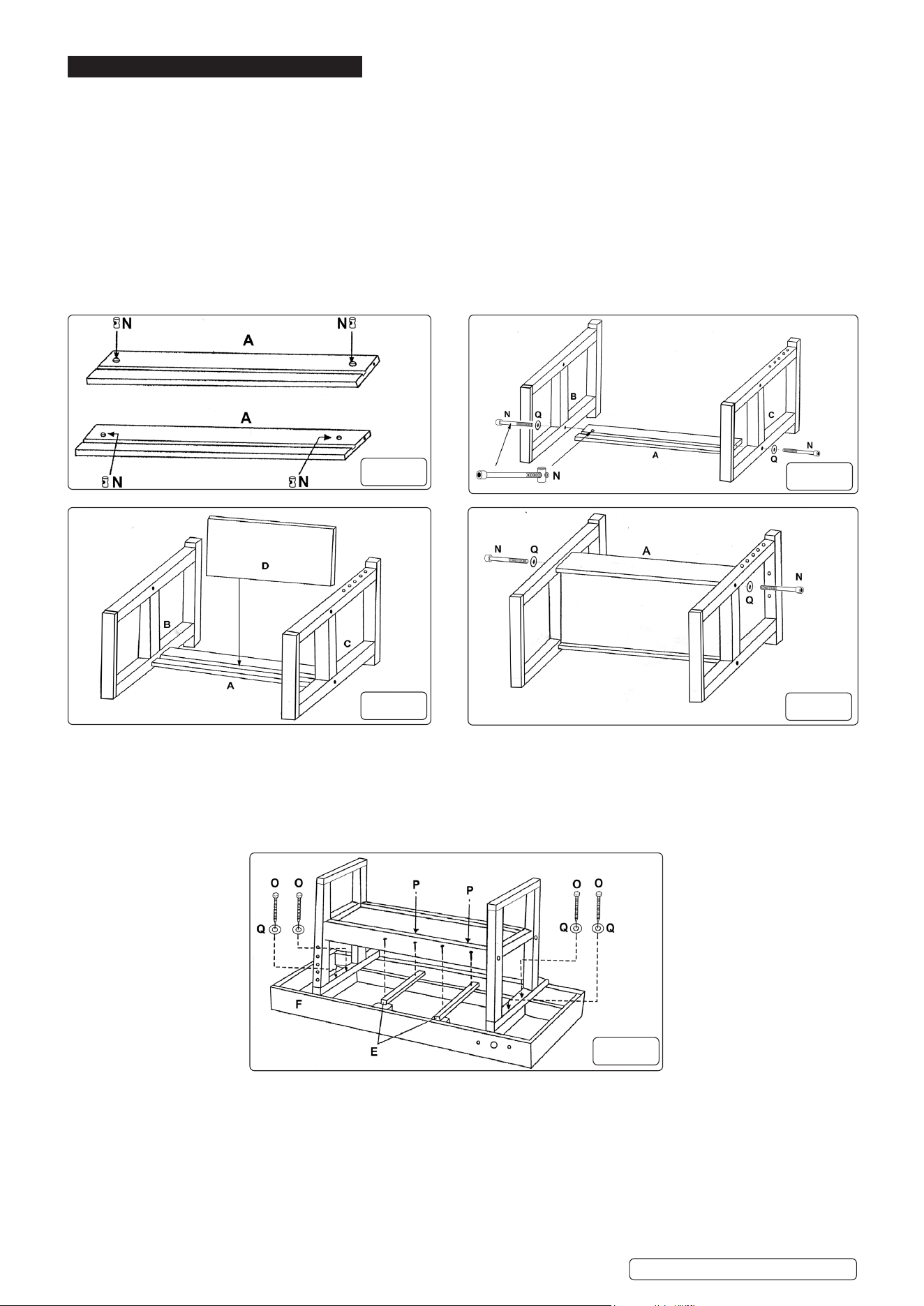
5.1. TABLE SUPPORT ASSEMBLY
5.1.1. Take the 2 threaded stubs from the two part connector (g 1 - N) and insert one each into hole at either end of leg brace (g 1 - A).
5.1.2. Rotate the screwdriver end slot so it is parallel to the longer edge of leg brace.
5.1.3. Repeat for other leg brace (g 1 - A).
5.1.4. Attach left hand end frame (g 2 - B) to cross brace (g 2- A) with two part connector socket cap bolt (g 2 - N) and washer
(g 2 - Q) and tighten with allen key (R).
5.1.5. Repeat for right hand end frame (g 2 - C).
NOTE: DO NOT fully tighten
5.1.6. Position shelf (g 3 - D) into the slot in leg brace (g 3 - A) and between end frames (g 2 - B & C).
5.1.7. Position the other leg brace (g 4 - A) slot onto the shelf with two part connector socket cap bolt (g 4 - N) and washer
(g 4 - Q) and tighten with allen key.
5.1.8. Ensure that the table support is at and square before fully tightening the two part connector socket cap bolts (N).
5.2. ATTACHING THE BENCH TOP
5.2.1. Place the bench top (g 5 - F) face down onto some protective material (e.g. packaging cardboard).
5.2.2. Attach the draw runners (g 5 - E) with the screws (g 5 - P) into the pre-drilled holes in the bench top.
NOTE: Ensure that the dowel pins are to placed to the front of the bench and that the draw runners are facing inwards.
5.2.3. Seeking assistance from another person turn the table support assembly upside down and locate into place onto the bench top
and secure into the pre-drilled holes with hex head screws (g 5 - O) and washers (g 5 - Q).
5.2.4. Again seeking assistance from another person turn the bench assembly back over onto its support frame.
5.3. DRAWER ASSEMBLY
5.3.1. Place the drawer sides (g 6 - H) on a at surface, with the dowel pins facing downwards.
NOTE: The drawer sides are handed.
5.3.2. Attach the drawer joining plates and screws (g 6 - S) into the pre-drilled holes.
5.3.3. Attach the drawer back (g 7 - J) to the drawer sides. Ensure that the slots are aligned on the inner faces.
5.3.4. Slide the drawer bottom (g 6 - I) into the slots on the drawer sides and the slot in the drawer back and push home.
5.3.5. Place the drawer front (g 8 - G) with the pre-drilled holes facing upwards onto a at surface.
5.3.6. Position the part assembled drawer so that the drawer joining plates align with the pre-drilled holes and secure with the remaining
screws (g 8 - S).
5.3.7. Place the assembled drawer onto the draw runners and slide into position.
g.4
g.5
AP1520.V2 Issue 1 23/04/21
Original Language Version
© Jack Sealey Limited
g.1
g.2
g.3
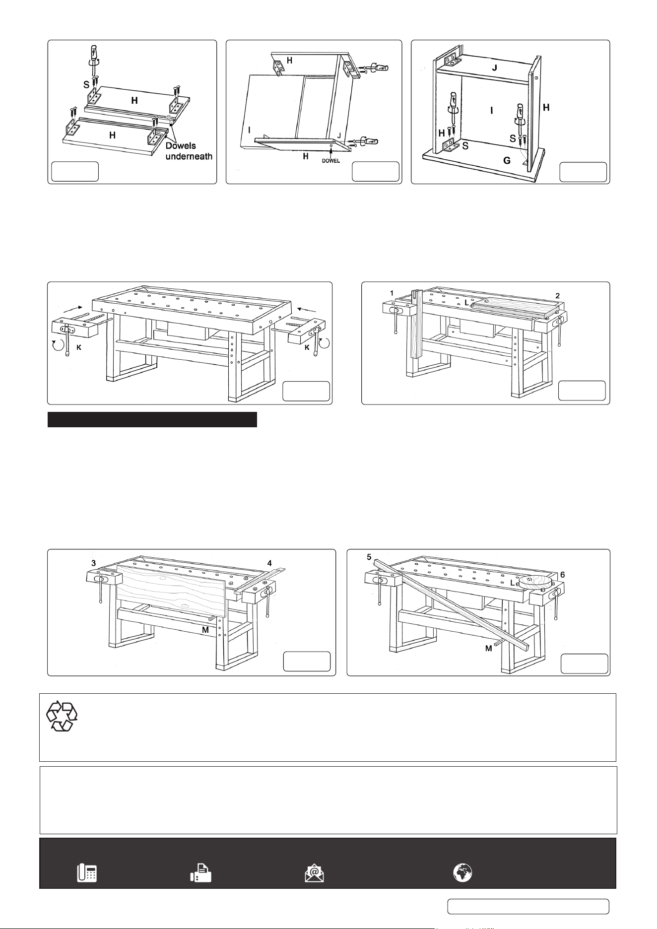
5.4. ATTACHING THE VICE
5.4.1. Securely hold the vice (g 9 - K) and introduce the three protruding shafts into the corresponding holes in the front of the work
bench.
5.4.2. Rotate the vice handle clockwise (central shaft) until the thread engages with the threaded casting situated on inside face of the
work bench (g 9 - K). Continue rotating the handle clockwise until the vice is closed.
5.4.3. Repeat for the other vice, located on the right hand side of the work bench.
5.4.4. To open the vice turn the handle anti-clockwise.
WARNING! Be aware that the vice will disengage from the work bench if the vice handle is rotated anti-clockwise too far.
6. BENCH CONFIGUREATION
6.1. The features of the work bench can be utilised to safely and rmly grip a workpiece in a varied number of ways.
6.1.1. Smaller workpieces can be held in either vice (g 10 - 1) or (g 11 - 4).
6.1.2. Larger workpieces (g 10 - 2) can be held on the top surface of work bench using the metal stops (g 10 - L) inserted into suitable
holes in the work bench top surface.
6.1.3. Larger sheet workpieces can be held using the front vice (g 11 - 3) and a wooden stop (g 11 - M) inserted into a suitable hole in
the right hand leg support.
6.1.4. Longer workpieces can be held at an angle using the front vice (g 12 - 5) and a wooden stop (g 12 - M) inserted into a suitable
hole in the right hand leg support.
6.1.5. Irregular shaped workpieces (g 12 - 6) can be held on the top surface of work bench using the metal stops (g 10 - L) inserted into
suitable holes in the work bench top surface and the vice, which can also be rotated to suit.
g.9
AP1520.V2 Issue 1 23/04/21
Original Language Version
© Jack Sealey Limited
g.10
g.11
g.12
g.8
g.7 g.6
Sealey Group, Kempson Way, Suffolk Business Park, Bury St Edmunds, Suffolk. IP32 7AR
01284 757500 01284 703534 sales@sealey.co.uk www.sealey.co.uk
Note: It is our policy to continually improve products and as such we reserve the right to alter data, specifications and component parts without prior
notice. Please note that other versions of this product are available. If you require documentation for alternative versions, please email or call
our technical team on technical@sealey.co.uk or 01284 757505.
Important: No Liability is accepted for incorrect use of this product.
Warranty: Guarantee is 12 months from purchase date, proof of which is required for any claim.
ENVIRONMENT PROTECTION
Recycle unwanted materials instead of disposing of them as waste. All tools, accessories and packaging should be sorted, taken to
a recycling centre and disposed of in a manner which is compatible with the environment. When the product becomes completely
unserviceable and requires disposal, drain any fluids (if applicable) into approved containers and dispose of the product and fluids
according to local regulations.