
November 2011
© 2011 Fluke Corporation. All rights reserved. Specifications are subject to change without notice.
All product names are trademarks of their respective companies.
28 II Ex
True-rms Digital Multimeter
Users Manual
1.888.610.7664 sales@GlobalTestSupply.com
Fluke-Direct.com

LIMITED WARRANTY AND LIMITATION OF LIABILITY
This Fluke product will be free from defects in material and workmanship for three years from the date of purchase. This
warranty does not cover fuses, disposable batteries, or damage from accident, neglect, misuse, alteration, contamination, or
abnormal conditions of operation or handling. Resellers are not authorized to extend any other warranty on Fluke’s behalf.
To obtain service during the warranty period, contact your nearest Fluke authorized service center to obtain return
authorization information, then send the product to that Service Center with a description of the problem.
THIS WARRANTY IS YOUR ONLY REMEDY. NO OTHER WARRANTIES, SUCH AS FITNESS FOR A PARTICULAR
PURPOSE, ARE EXPRESSED OR IMPLIED. FLUKE IS NOT LIABLE FOR ANY SPECIAL, INDIRECT, INCIDENTAL OR
CONSEQUENTIAL DAMAGES OR LOSSES, ARISING FROM ANY CAUSE OR THEORY. Since some states or countries
do not allow the exclusion or limitation of an implied warranty or of incidental or consequential damages, this limitation of
liability may not apply to you.
Fluke Corporation
P.O. Box 9090
Everett, WA 98206-9090
U.S.A.
Fluke Europe B.V.
P.O. Box 1186
5602 BD Eindhoven
The Netherlands
11/99
1.888.610.7664 sales@GlobalTestSupply.com
Fluke-Direct.com

i
Table of Contents
Title Page
Introduction .................................................................................................................... 1
How to Contact Fluke ..................................................................................................... 1
Safety Information .......................................................................................................... 2
EX Safety Information .................................................................................................... 2
Errors and Load Restrictions ..................................................................................... 6
Ex-Certification Data .................................................................................................. 7
Features ......................................................................................................................... 9
Automatic Power-Off ................................................................................................. 15
Input Alert™ Feature ................................................................................................. 15
Power-Up Options ..................................................................................................... 16
How to Make Measurements .......................................................................................... 17
AC and DC Voltage Measurements ........................................................................... 17
Zero Input Behavior of True-rms Meters .................................................................... 18
Low-Pass Filter .......................................................................................................... 18
Temperature Measurements ..................................................................................... 19
1.888.610.7664 sales@GlobalTestSupply.com
Fluke-Direct.com

28 II Ex
Users Manual
ii
Continuity Tests ........................................................................................................ 20
Resistance Measurements ....................................................................................... 22
How to Use Conductance for High Resistance or Leakage Tests ............................ 24
Capacitance Measurements ..................................................................................... 25
Diode Tests ............................................................................................................... 26
AC or DC Current Measurements ............................................................................. 28
Frequency Measurements ........................................................................................ 31
Duty Cycle Measurements ........................................................................................ 33
How to Determine Pulse Width ................................................................................. 34
HiRes Mode ................................................................................................................... 34
MIN MAX Recording Mode ............................................................................................ 35
Smooth Feature (Power Up Option Only) ...................................................................... 35
AutoHOLD
Mode ........................................................................................................... 37
Relative Mode ................................................................................................................ 37
Maintenance .................................................................................................................. 38
General Maintenance ................................................................................................ 38
Fuse Test .................................................................................................................. 38
How to Replace the Batteries.................................................................................... 39
How to Replace the Fuses ........................................................................................ 42
Service and Parts .......................................................................................................... 42
General Specifications ................................................................................................... 46
Detailed Specifications .................................................................................................. 48
AC Voltage ................................................................................................................ 48
DC Voltage, Conductance, and Resistance .............................................................. 49
Temperature ............................................................................................................. 50
AC Current ................................................................................................................ 50
DC Current ................................................................................................................ 51
Capacitance .............................................................................................................. 51
Diode ........................................................................................................................ 52
1.888.610.7664 sales@GlobalTestSupply.com
Fluke-Direct.com

Contents (continued)
iii
Frequency ................................................................................................................. 52
Frequency Counter Sensitivity and Trigger Levels .................................................... 52
Duty Cycle (Vdc and mVdc) ...................................................................................... 53
Input Characteristics .................................................................................................. 53
MIN MAX Recording .................................................................................................. 54
1.888.610.7664 sales@GlobalTestSupply.com
Fluke-Direct.com

28 II Ex
Users Manual
iv
1.888.610.7664 sales@GlobalTestSupply.com
Fluke-Direct.com

v
List of Tables
Table Title Page
1. Symbols ................................................................................................................................. 8
2. Inputs .................................................................................................................................... 9
3. Rotary Switch Positions ......................................................................................................... 10
4. Pushbuttons .......................................................................................................................... 11
5. Display Features ................................................................................................................... 13
6. Power-Up Options ................................................................................................................. 16
7. Functions and Trigger Levels for Frequency Measurements ................................................. 32
8. MIN MAX Functions .............................................................................................................. 36
9. Approved Batteries ................................................................................................................ 40
10. Replacement Parts ................................................................................................................ 43
11. Accessories ........................................................................................................................... 45
1.888.610.7664 sales@GlobalTestSupply.com
Fluke-Direct.com

28 II Ex
Users Manual
vi
1.888.610.7664 sales@GlobalTestSupply.com
Fluke-Direct.com

vii
List of Figures
Figure Title Page
1. Display Features ................................................................................................................... 13
2. AC and DC Voltage Measurements ...................................................................................... 17
3. Low-Pass Filter ...................................................................................................................... 19
4. Continuity Tests ..................................................................................................................... 21
5. Resistance Measurements .................................................................................................... 23
6. Capacitance Measurements .................................................................................................. 25
7. Diode Tests ........................................................................................................................... 27
8. Current Measurements .......................................................................................................... 29
9. Components of Duty Cycle Measurements ........................................................................... 33
10. Current Fuse Test ................................................................................................................. 39
11. Battery and Fuse Replacement ............................................................................................. 41
12. Replacement Parts ................................................................................................................ 44
1.888.610.7664 sales@GlobalTestSupply.com
Fluke-Direct.com

28 II Ex
Users Manual
viii
1.888.610.7664 sales@GlobalTestSupply.com
Fluke-Direct.com

1
Introduction
WX Warning
Read “Safety Information” before using the
Product.
The 28 II Ex Digital Multimeter (the Product) is a compact
easy to operate measurement tool for electrical and
electronic circuits.
The Product is designed for operation in potentially
explosive areas of Zone 1, 2, 21, 22, and MI as specified
in Directive 1999/92/EC (ATEX 137) and 94/9/EC (ATEX
95). There can be dangerous consequences If you do not
follow these instructions.
Read the entire Users Manual before you use the
Product.
How to Contact Fluke
To contact Fluke, call one of the following telephone
numbers:
• Technical Support USA: 1-800-44-FLUKE (1-800-
443-5853)
• Calibration/Repair USA: 1-888-99-FLUKE (1-888-
993-5853)
• Canada: 1-800-36-FLUKE (1-800-363-5853)
• Europe: +31 402-675-200
• Japan: +81-3-6714-3114
• Singapore: +65-738-5655
• Anywhere in the world: +1-425-446-5500
Or, visit Fluke's website at www.fluke.com.
To register your product, visit http://register.fluke.com.
To see, print, or download the latest manual supplement,
visit http://us.fluke.com/usen/support/manuals.
1.888.610.7664 sales@GlobalTestSupply.com
Fluke-Direct.com

28 II Ex
Users Manual
2
Safety Information
The Product complies with:
• ISA-82.02.01
• CAN/CSA-C22.2 No. 61010-1-04
• IEC Standard No. 61010-1:2001
• Measurement Category III, 1000V, Pollution
Degree 2
• Measurement Category IV, 600V, Pollution
Degree 2
• Industrial use in potentially explosive areas of
zone 1, 2, 21, 22, or MI, in accordance with
ATEX requirements (ATEX 137) (see the EX
safety instructions & regulations section)
In this manual, a Warning identifies conditions and
actions that can be dangerous to the user. A Caution
identifies conditions and actions that can cause damage
to the Product or the equipment under test.
Symbols used on the Product and in this manual are
explained in Table 1.
To ensure safe operation of the Product, obey all
instructions and warnings contained in this manual.
EX Safety Information
Note
Go to www.ecom-ex.com or www.fluke.com
download the EC declaration of conformity and
Ex certificate for this product. You can also order
them from Fluke.
This manual contains information and safety regulations
that must be followed for safe, reliable operation of the
Product in hazardous areas under the described
conditions. Failure to follow the information and
instructions can have dangerous consequences, or may
contravene applicable legislation.
Please read through this manual before you start to use
the Product.
If there is a question (because of translation and/or
printing errors), refer to the English manual.
1.888.610.7664 sales@GlobalTestSupply.com
Fluke-Direct.com

True-rms Digital Multimeter
EX Safety Information
3
WX Warning
To prevent electric shock or personal injury
while in Ex-HAZARDOUS areas, follow these
guidelines:
• Do not open the Product while in an
Ex-hazardous area.
• Change the Product’s batteries only
outside Ex-hazardous areas.
• Do not take spare batteries into
Ex-hazardous areas.
• Use only type-approved batteries in the
Product. See the “How to Replace the
Batteries” section for a list of approved
batteries.
• Do not replace fuses while in an
Ex-hazardous area.
• Use only fuses approved for
Ex-hazardous areas in this Product. See
the “How to Replace the Fuses” section
for a list of approved fuses.
• Use the Product only when the specified
connection values are met.
• After you use the Product on a non-
intrinsically safe protected circuit, wait
3 minutes before you take the Product
into an Ex-hazardous area.
• The Product must be completely and
securely fitted in the red holster while it
is in an Ex-hazardous area.
• Use only approved accessories with this
Product in Ex-hazardous areas.
• Do not use the Product in aggressive
acidic or alkaline solutions.
• Do not use the Product in zone 0 and 20.
Measurements on intrinsically safe
connections that go into zone 0 or 20 are
permitted if the connection values are
met.
1.888.610.7664 sales@GlobalTestSupply.com
Fluke-Direct.com

28 II Ex
Users Manual
4
WX Warning
To prevent personal injury in mining
hazardous areas:
• Avoid extreme mechanical burdens. The
Product can withstand impacts with an
energy of seven joules at -20 °C.
• Do not allow the Product to come in
permanent contact with oils, hydraulic
fluid, or grease.
• Do not install the Product in a fixed
installation.
WX Warning
To prevent possible electrical shock, fire, or
personal injury in ALL areas of operation:
• Read all safety Information before you
use the Product.
• Comply with local and national safety
codes. Use personal protective
equipment (approved rubber gloves, face
protection, and flame-resistant clothes)
to prevent shock and arc blast injury
where hazardous live conductors are
exposed
• See the “EX Safety Information” section
for additional warnings on Product use
in hazardous areas.
• Use the Product only as specified, or the
protection supplied by the Product can
be compromised.
• Do not use the Product in damp or wet
environments.
• Do not exceed the Measurement
Category (CAT) rating of the lowest rated
individual component of a Product,
probe, or accessory.
• Examine the case before you use the
Product. Look for cracks or missing
plastic. Carefully look at the insulation
around the terminals.
• Do not use test leads if they are
damaged. Examine the test leads for
damaged insulation, exposed metal, or if
the wear indicator shows. Check test
lead continuity.
1.888.610.7664 sales@GlobalTestSupply.com
Fluke-Direct.com

True-rms Digital Multimeter
EX Safety Information
5
• Do not work alone.
• Do not touch voltages >30 V ac rms, 42 V
ac peak, or 60 V dc.
• Use only correct measurement category
(CAT), voltage, and amperage rated
probes, test leads, and adapters for the
measurement.
• Remove all probes, test leads, and
accessories that are not necessary for
the measurement.
• Keep fingers behind the finger guards on
the probes.
• Limit operation to the specified
measurement category, voltage, or
amperage ratings.
• Measure a known voltage first to make
sure the Product operates correctly.
• Measure for hazardous voltage without
the Low-Pass Filter.
• Do not apply more than the rated
voltage, between the terminals or
between each terminal and earth ground.
• Do not touch the probes to a voltage
source when the test leads are
connected to the current terminals.
• Connect the common test lead before
the live test lead and remove the live test
lead before the common test lead.
• Replace the batteries when the low
battery indicator shows to prevent
incorrect measurements.
• The battery door must be closed and
locked before you operate the Product.
• Do not use the Product if it operates
incorrectly.
• Do not use and disable the Product if it
is damaged.
1.888.610.7664 sales@GlobalTestSupply.com
Fluke-Direct.com

28 II Ex
Users Manual
6
WCaution
To avoid possible damage to the Product or
to the equipment under test, follow these
guidelines:
• Disconnect circuit power and discharge
all high-voltage capacitors before testing
resistance, continuity, diodes, or
capacitance.
• Use the proper terminals, function, and
range for all measurements.
• Before measuring current, check the
fuses in the Product. (See “Fuse Test”.)
Errors and Load Restrictions
If there is a question that the safety or integrity of this
Product is compromised, remove it from operation and
the Ex-hazardous areas immediately. Also, do whatever
is necessary to prevent Product operation by others until
the Product is examined by an ecom certified technician.
It is recommended that you send the Product to the
manufacturer to be examined.
Because the safety and reliability of the Product can be at
risk, do not operate the Product if:
• Visible damage is found in the housing of the
Product.
• The Product has had an excessive load put on it for
which it is not designed.
• The Product was not stored correctly.
• The Product has sustained damage in transit.
• Illegible inscriptions or lettering shows on the
Product.
• A Product malfunction occurs.
• Obvious measurement inaccuracies occur.
• Measurements/simulations are no longer possible
with the Product.
• Permitted tolerances or threshold values were
exceeded.
1.888.610.7664 sales@GlobalTestSupply.com
Fluke-Direct.com

True-rms Digital Multimeter
EX Safety Information
7
Ex-Certification Data
• Ex-Type certificate no:
• Ex-Designation:
• Power Supply:
• CE: CE0102
• Operating Temperature: -15 °C to 50 °C
• Storage Temperature: -55 °C to +60 °C
• Batteries: 3 AAA Alkaline batteries, NEDA 24A IEC
LR03. Table 9 shows the approved batteries for this
Product.
For connections to intrinsically-safe circuits, observe
these Product connections:
Voltage – measurement input U
i
= 65 V:
U
0
= 9.54 V U
i
= 65 V
C
0
= 3.6 μF C
i
= negligible
I
0
= 3.7 mA I
i
= negligible
L
0
= 1000 mH L
i
= negligible
P
0
= 3.4 mW
Current – measurement input I
i
= 5 A:
U
0
= 0 V U
i
= 65 V
C
0
= 1000 μF C
i
= negligible
I
0
= 9.7 μA I
i
= 5 A
L
0
= 1000 mH L
i
= negligible
P
0
= 0 mWH
mA/μA Jack
U
0
= 1.94 V U
i
= 65 V
C
0
= 1000 μF C
i
= negligible
I
0
= 9.7 μA I
i
= Internally limited by a 440 mA fuse
L
0
= 1000 mH L
i
= negligible
P
0
= negligible
For measurements on protected electric circuits:
• Approved for Zones 2 and 1, device group II,
explosion group IIC (explosive gases, vapors and
mist), temperature class T4.
• Approved for Zones 21 and 22, device group II,
explosion group IIIC, conducting and non-conducting
dust, fibers, and flyings.
• Approved for use in mines. Device group I, explosion
group I, methane, and coal dust.
1.888.610.7664 sales@GlobalTestSupply.com
Fluke-Direct.com

28 II Ex
Users Manual
8
Table 1. Symbols
AC (Alternating Current) J Earth ground
DC (Direct Current) I Fuse
X Hazardous voltage P Conforms to European Union directives.
W
Risk of Danger. Important information. See
Manual.
Diode
Battery. Low battery when displayed. T Double insulated
R Continuity test or continuity beeper tone.
Capacitance
CAT III
IEC Overvoltage Category III
CAT III equipment is designed to protect
against transients in equipment in fixed-
equipment installations, such as
distribution panels, feeders and short
branch circuits, and lighting systems in
large buildings.
CAT IV
IEC Overvoltage Category IV
CAT IV equipment is designed to protect against
transients from the primary supply level, such as an
electricity Product or an overhead or underground
utility service.
(
Conforms to ATEX directive.
Conforms to relevant Australian standards.
®
Inspected and licensed by TÜV Product
Services.
Æ
Conforms to CAN/CSA-C22.2 No. 61010-1 2
nd
, +
Amendment 1.
~
Do not dispose of this product as unsorted municipal waste. Go to Fluke’s website for recycling information.
1.888.610.7664 sales@GlobalTestSupply.com
Fluke-Direct.com
True-rms Digital Multimeter
Features
9
Features
Tables 2 through 5 show the features of the Product.
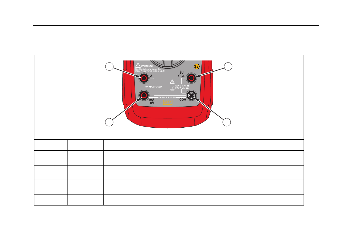
Table 2. Inputs
1
2
4
3
grt01.eps
Item Terminal Description
A
Input for 0 A to 10.00 A current (10 A to 20 A overload for 30 seconds maximum),
current frequency, and duty cycle measurements.
Input for voltage, continuity, resistance, diode, capacitance, frequency, temperature,
and duty cycle measurements.
Input for 0 μA to 400 mA current measurements (600 mA for 18 hrs) and current
frequency and duty cycle.
COM
Return terminal for all measurements.
1.888.610.7664 sales@GlobalTestSupply.com
Fluke-Direct.com

28 II Ex
Users Manual
10
Table 3. Rotary Switch Positions
Switch Position
Function
Any Position When the Product is turned on, the Product model number briefly shows on the display.
J
AC voltage measurement
Push
(yellow) for low-pass filter (K)
L DC voltage measurement
M
600 mV dc voltage range
Push (yellow) for temperature ()
N
Push E for continuity test.
e Resistance measurement
Push (yellow) for capacitance measurement.
O Diode test
P
AC current measurements from 0 mA to 10.00 A
Push
(yellow) for dc current measurements, from 0 mA to 10.00 A.
Q
AC current measurements from 0 μA to 6000 μA
Push
(yellow) for dc current measurements from 0 μA to 6000 μA.
1.888.610.7664 sales@GlobalTestSupply.com
Fluke-Direct.com

True-rms Digital Multimeter
Features
11
Table 4. Pushbuttons
Button
Switch
Position
Function
(Yellow)
Set to capacitance
Set to temperature
Turn on ac low-pass filter
Set dc or ac current
Set dc or ac current
C
Any
position
Change and set the range for the set function. To go to autoranging, hold the button down for
1 second.
M
Sets to °C or °F.
D
Any
position
MIN MAX
recording
Frequency
counter
AutoHOLD (formerly TouchHold) captures the current measurement on the display. When a
new, stable measurement is sensed, the Product beeps and shows the new measurement.
Stops and starts recording. Does not erase recorded values.
Stops and starts the frequency counter.
1.888.610.7664 sales@GlobalTestSupply.com
Fluke-Direct.com

28 II Ex
Users Manual
12
Table 4. Pushbuttons (cont.)
Button
Switch
Position
Function
E
Continuity
N
MIN MAX
recording
Hz, Duty
Cycle
Toggle the continuity beeper on and off.
Switches between Peak (250 μs) and Normal (100 ms) response times.
Toggles the Product to trigger on positive or negative slope.
H
Any
position
Turns on the button backlight and display backlight, makes them brighter, and turns off the
backlights. Hold
H down for 1 second to enter the HiRes digit mode. The “HiRes” icon shows in
the display. To go back to the 3-1/2 digit mode, hold
H down for 1 second. HiRes=19.999.
Any
position
Starts recording of minimum and maximum values. Steps the display through MAX, MIN, AVG
(average), and current measurement. Cancels MIN MAX (hold for 1 second)
F
(Relative
mode)
Any
position
Stores the current measurement as a reference for subsequent measurements. The display is
zeroed, and the stored measurement is subtracted from all subsequent measurements.
G
Any
position
except
diode test
Push G for frequency measurements.
Push again to go to duty cycle mode.
1.888.610.7664 sales@GlobalTestSupply.com
Fluke-Direct.com
True-rms Digital Multimeter
Features
13
6
5
4
3
2
7
8 9 10 11
12
13
14
15
161 17
grt09.eps
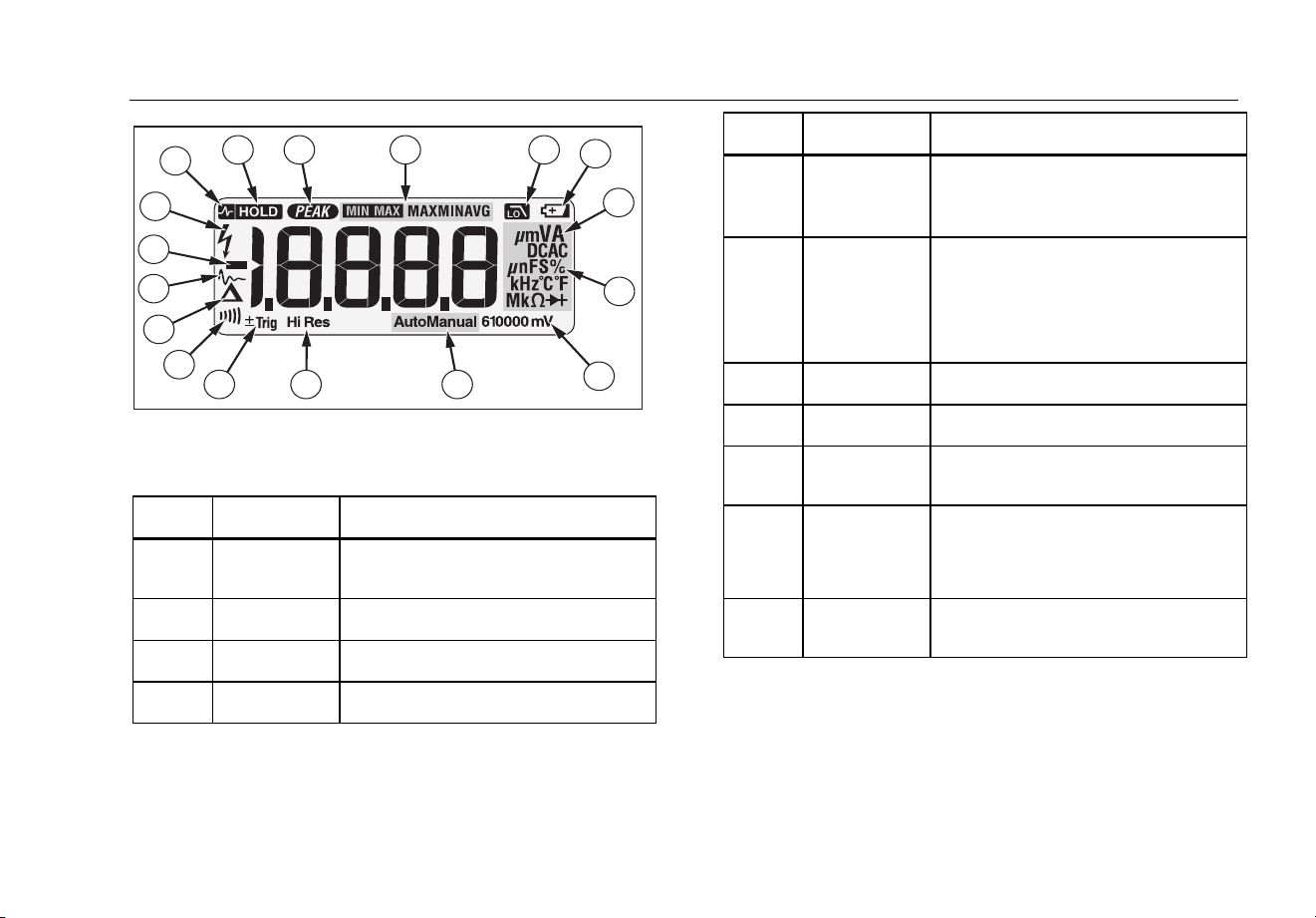
Figure 1. Display Features
Table 5. Display Features
Number Feature Indication
±Trig
Positive or negative slope indicator
for Hz/duty cycle triggering.
X
The continuity beeper is on.
W
Relative (REL) mode is active.
Smoothing is active.
Number Feature Indication
-
Negative measurement. In relative
mode, this sign shows that the input
is less than the stored reference.
Z
High voltage present at the input.
Appears if the input voltage is 30 V
or greater (ac or dc). Also shows in
low-pass filter mode. Also shows in
cal, Hz, and duty cycle modes.
RS
AutoHOLD is active.
S
Display HOLD is active.
Peak Min Max modes and the
response time is 250 μs.
€
MAX MIN
AVG
Minimum-maximum recording mode.
K
Low-pass filter mode. See “Low-
pass Filter”.
1.888.610.7664 sales@GlobalTestSupply.com
Fluke-Direct.com

28 II Ex
Users Manual
14
Table 5. Display Features (cont.)
Number Feature Indication
Low battery. XW Warning: To
avoid false readings, which
could lead to possible electric
shock or personal injury,
replace the battery as soon as
the battery indicator appears.
A, μA, mA
amperes (amps), microamp, milliamp
V, mV
volts, millivolts
μF, nF
microfarad, nanofarad
nS
nanosiemens
%
Percent. Used for duty cycle
measurements.
Ω, MΩ, kΩ
ohm, megohm, kilohm
Hz, kHz
hertz, kilohertz
O
Diode test mode
AC DC
Alternating current, direct current
Number Feature Indication
°C °F
Degrees Celsius, Degrees
Fahrenheit
610000 mV
Displays selected range
Auto
Autorange mode. Automatically
selects the range with the best
resolution.
Manual
Manual range mode
HiRes
High resolution (Hi Res) mode
HiRes=19,999
1.888.610.7664 sales@GlobalTestSupply.com
Fluke-Direct.com

True-rms Digital Multimeter
Features
15
Table 5. Display Features (cont.)
Number Feature Indication
--
0L
Overload condition is detected.
Error Messages
bAtt
Replace the battery immediately.
di'c
In the capacitance function, too much electrical
charge is on the capacitor under test.
CAL Err
Invalid calibration data. Calibrate Product.
EEPr Err
Invalid EEPROM data. Have the Product serviced.
0PEn
Open thermocouple detected.
F2_
Invalid model. Have the Product serviced.
LEAd
W Test lead alert. Shows when the test leads are in
the
A or mA/μA terminal and the selected rotary
switch position does not correspond to the terminal
being used.
Automatic Power-Off
The Product automatically turns off if you do not turn the
rotary switch or push a button for 30 minutes. If MIN MAX
Recording mode is on, the Product will not turn off. Refer
to Table 6 to disable automatic power-off.
Input Alert™ Feature
If a test lead is connected to the mA/μA or A terminal, but
the rotary switch is not set to the correct current position,
the beeper warns you by making a chirping sound and
the display flashes “LEAd”. This warning is intended to
stop you from attempting to measure voltage, continuity,
resistance, capacitance, or diode values with the leads
are plugged into a current terminal.
W Caution
To prevent damage, do not put the probes
across (in parallel with) a circuit with power
with a lead connected to a current terminal.
This can cause damage to a circuit with
power and blow the Product fuse. This can
occur because the resistance through the
current terminals of the Product is very low,
and causes a short circuit.
1.888.610.7664 sales@GlobalTestSupply.com
Fluke-Direct.com

28 II Ex
Users Manual
16
Power-Up Options
To set a power-up option, push a button down while you energize the Product. Table 6 shows the power-up option.
Table 6. Power-Up Options
Button Power-Up Option
(Yellow)
Disables automatic power-off feature (Product normally powers off in 30 minutes).
The Product reads “PoFF” until is released.
Sets the Product in calibration mode and prompts for a password.
The Product shows “CAL” in the display and enters calibration mode. See 28 II Ex Calibration Information.
C Turns on the smoothing feature. The Product reads “'---” until C is released.
D Turns on all LCD segments.
E Disables the beeper for all functions. The Product reads “bEEP” until E is released.
H
Disables auto backlight off (backlight normally disables after 2 minutes). The Product reads “LoFF” until H
is released.
G
Sets the Product into the high impedance mode when the mV dc function is used.
The Product reads “Hi2” until G is released.
1.888.610.7664 sales@GlobalTestSupply.com
Fluke-Direct.com
True-rms Digital Multimeter
How to Make Measurements
17
How to Make Measurements
AC and DC Voltage Measurements
The Product features true-rms measurements, which are
accurate for distorted sine waves and other waveforms
(with no dc offset) such as square waves, triangle waves,
and staircase waves.
The voltage ranges of the Product are 600.0 mV, 6.000 V,
60.00 V, 600.0 V, and 1000 V. The select the 600.0 mV
dc range, turn the rotary switch to mV.
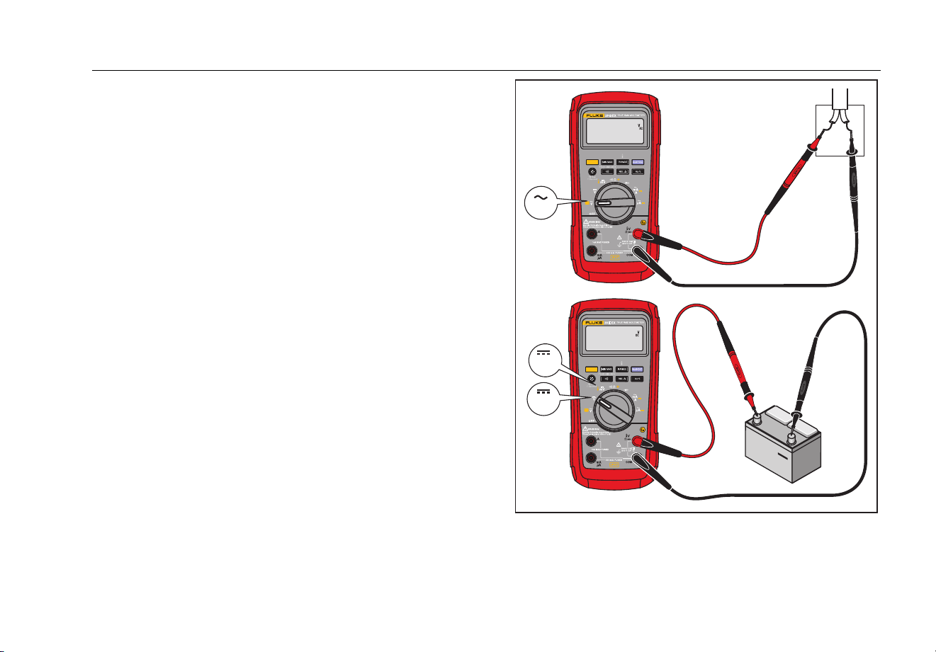
Refer to Figure 2 to measure ac or dc voltage.
Switch Box
AC Voltage
+
DC Voltage
V
V
mV
grt02.eps
Figure 2. AC and DC Voltage Measurements
1.888.610.7664 sales@GlobalTestSupply.com
Fluke-Direct.com

28 II Ex
Users Manual
18
When you measure voltage, the Product puts
approximately 10-MΩ (10,000,000 Ω) impedance in
parallel with the circuit. This loading effect can cause
measurement errors in high-impedance circuits. In most
cases, the error is negligible (0.1 % or less) if the circuit
impedance is 10 kΩ (10,000 Ω) or less.
For better accuracy when you measure the dc offset of an
ac voltage, measure the ac voltage first. Record the ac
voltage range, then manually select a dc voltage range
equal to or higher than the ac range. This procedure has
better accuracy of the dc measurement because the input
protection circuits are disabled.
Zero Input Behavior of True-rms Meters
True-rms meters accurately measure distorted
waveforms, but when the input leads are shorted together
in the ac functions, the Product shows a measurement
between 1 and 30 counts. When the test leads are open,
the measurements can change from interference. These
offset measurements are common. They do not change
the ac measurement accuracy of the Product for the
specified measurement ranges.
Unspecified input levels are:
• AC voltage: below 3 % of 600 mV ac, or 18 mV ac
• AC current: below 3 % of 60 mA ac, or 1.8 mA ac
• AC current: below 3 % of 600 μA ac, or 18 μA ac
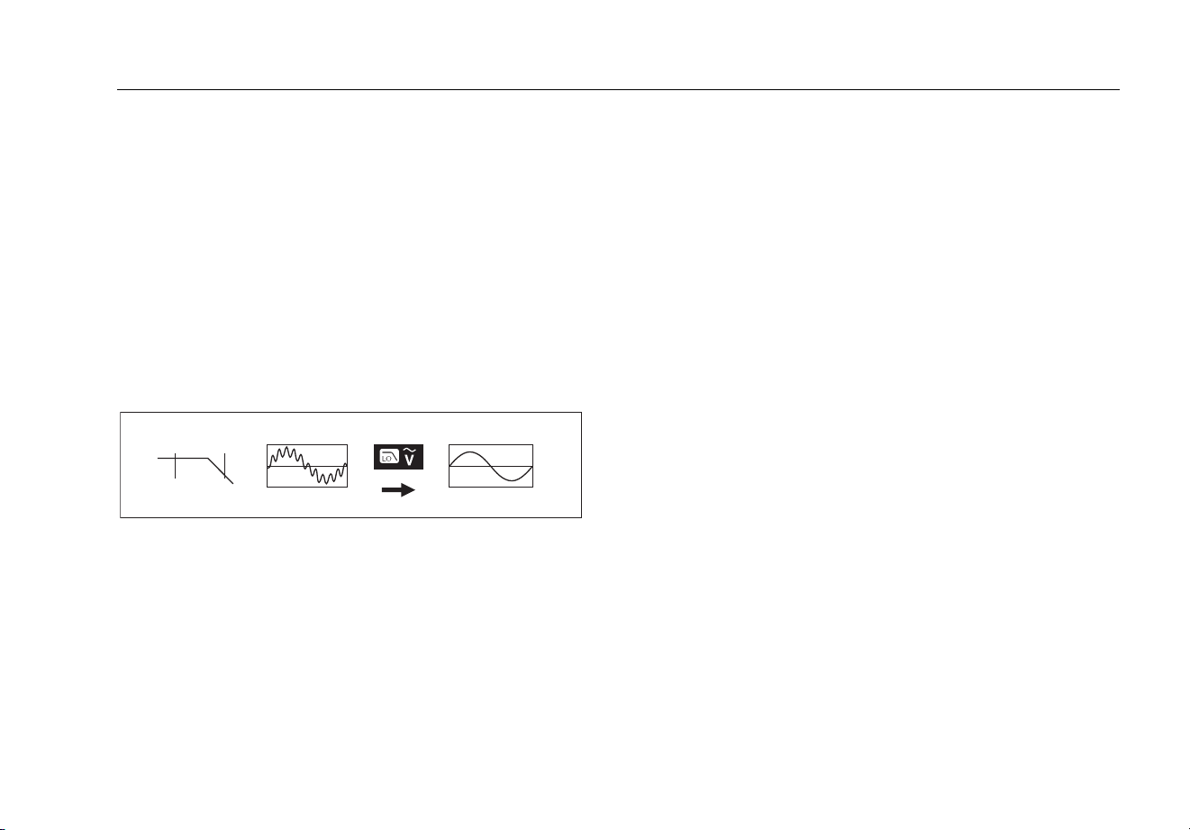
Low-Pass Filter
The Product is has an ac low-pass filter. When you
measure ac voltage or ac frequency, push to set
the low-pass filter mode (K). The Product measures in
the chosen mode, but the signal diverts through a filter
that stops unwanted voltages more than 1 kHz, refer to
Figure 3. The lower frequency voltages go through with
decreased accuracy to the measurement less than 1 kHz.
The low-pass filter can get you better measurement
performance on composite sine waves that are typically
found on inverters and variable-frequency motor drives.
1.888.610.7664 sales@GlobalTestSupply.com
Fluke-Direct.com
True-rms Digital Multimeter
How to Make Measurements
19
XW Warning
To prevent electric shock or personal injury,
do not use the low-pass filter when you
measure for hazardous voltages. Voltages
larger than what is shown can be present.
First, make a voltage measurement without
the filter to see if a hazardous voltage is
present. Then, select the filter.
Note
When the low-pass filter is selected, the Product
goes to manual range mode. Push to set
the range. The Product does not autorange with
the low-pass filter set.
1 kHz
100 Hz
aom11f.eps
Figure 3. Low-Pass Filter
Temperature Measurements
The Product measures the temperature of a type-K
thermocouple (included). Push C to toggle between
degrees Celsius (°C) or degrees Fahrenheit (°F).
W Caution
To prevent damage to the Product or other
equipment, remember that while the Product
is rated for -200.0 °C to +1090.0 °C (-328.0 °F
to 1994 °F), the included type-K
thermocouple is rated to 260 °C. For
temperatures out of that range, use a higher
rated thermocouple.
Display ranges are -200.0 °C to +1090 °C and -328.0 °F
to 1994 °F. Measurements outside these ranges show 0L
in the display. When there is no thermocouple connected,
the display also reads 0PEn.
To measure temperature:
1. Connect a type-K thermocouple to the COM and
terminals of the Product.
2. Turn the rotary switch to M.
3. Push to enter temperature mode.
4. Push C to choose Celsius or Fahrenheit.
1.888.610.7664 sales@GlobalTestSupply.com
Fluke-Direct.com

28 II Ex
Users Manual
20
Continuity Tests
WCaution
To prevent damage to the Product or to the
equipment under test, disconnect circuit
power and discharge all high-voltage
capacitors before you do a continuity test.
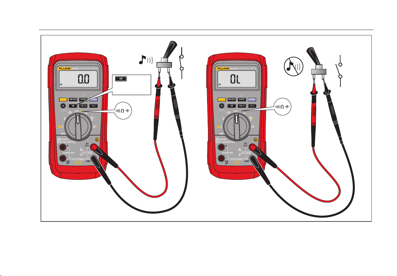
The continuity test has a beeper that sounds when a
circuit is complete. You can do continuity tests and not
have to look at the display.
To do a continuity test, set up the Product as shown in
Figure 4.
Push E to turn the continuity beeper on or off.
The continuity function senses intermittent opens and
shorts that last as little as 1 ms. A brief short causes the
Product to emit a short beep.
1.888.610.7664 sales@GlobalTestSupply.com
Fluke-Direct.com
True-rms Digital Multimeter
How to Make Measurements
21
For in-circuit tests, turn circuit power off.
OFF
(open)
ON
(closed)
Activates
continuity
beeper
grt03.eps
Figure 4. Continuity Tests
1.888.610.7664 sales@GlobalTestSupply.com
Fluke-Direct.com

28 II Ex
Users Manual
22
Resistance Measurements
WCaution
To prevent damage to the Product or to the
equipment under test, disconnect the power
and discharge all high-voltage capacitors
before you measure resistance.
The Product sends a small current through the circuit to
measure resistance. Because this current flows through
all possible paths between the probes, the resistance
measurement shows the total resistance of all paths
between the probes.
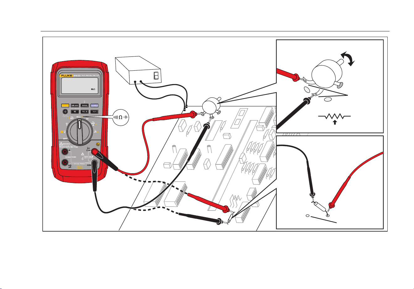
The resistance ranges of the Product are 600.0 Ω,
6.000 kΩ, 60.00 kΩ, 600.0 kΩ, 6.000 MΩ, and 50.00 MΩ.
Connect the Product to the circuit as shown in Figure 5 to
measure resistance.
Some guidelines for resistance measurements are:
• The measured value of a resistor in a circuit can be
different than the resistor's rated value.
• The test leads can add 0.1 Ω to 0.2 Ω of error to
resistance measurements. To test the leads, touch
the probe tips together and read the resistance of the
leads. If necessary, you can use the relative (REL)
mode to automatically subtract this value.
• The resistance function can output a voltage
sufficient to forward-bias silicon diode or transistor
junctions, which can cause them to conduct. If this
occurs, push C to apply a lower current in the
next higher range. If the value is higher, use the
higher value. Refer to the Input Characteristics table
in the specifications section for typical short-circuit
currents.
1.888.610.7664 sales@GlobalTestSupply.com
Fluke-Direct.com
True-rms Digital Multimeter
How to Make Measurements
23
1
2
3
1
3
2
Circuit Power
OFF
In-Circuit Resistance Measurements
Disconnect
Isolating a Potentiometer
Disconnect
Isolating a Resistor
grt04.eps
Figure 5. Resistance Measurements
1.888.610.7664 sales@GlobalTestSupply.com
Fluke-Direct.com

28 II Ex
Users Manual
24
How to Use Conductance for High Resistance or
Leakage Tests
Conductance, the inverse of resistance, is a measure of
how easily current goes through a circuit. High values of
conductance are the same as low values of resistance.
The 60-nS range of the Product measures conductance
in nanosiemens (1 nS = 0.000000001 siemens). Because
such small quantities of conductance are equal to very
high resistance, the nS range lets you measure the
resistance of components with a maximum of
100,000 MΩ, 1/1 nS = 1,000 MΩ.
To measure conductance, set up the Product for
resistance measurement as shown in Figure 5, then push
C until the nS indicator shows in the display.
Some guidelines for conductance measurements are:
• High-resistance measurements are susceptible to
electrical noise. To smooth out most noisy
measurements, start the MIN MAX recording mode;
then step to the average (AVG) reading.
• It is usual to have a conductance measurement in
the display with the test leads open. To make sure
you make accurate measurements, use the relative
(REL) mode to subtract this open measurement
value.
1.888.610.7664 sales@GlobalTestSupply.com
Fluke-Direct.com
True-rms Digital Multimeter
How to Make Measurements
25
Capacitance Measurements
WCaution
To prevent damage to the Product or to the
equipment under test, disconnect circuit
power and discharge all high-voltage
capacitors before you measure capacitance.
Use the dc voltage function to make sure that
the capacitor is discharged.
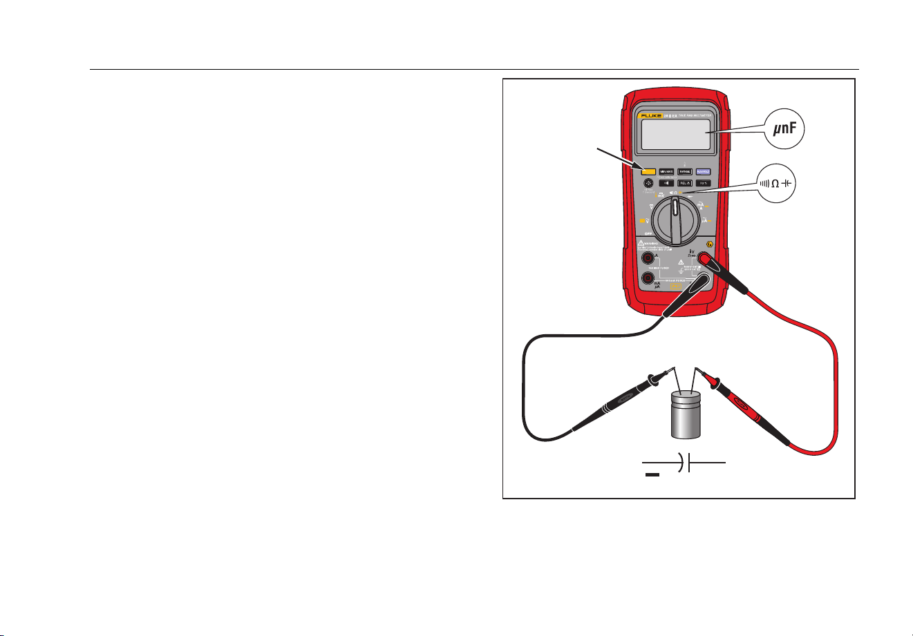
The capacitance ranges of the Product are 10.00 nF,
100.0 nF, 1.000 μF, 10.00 μF, 100.0 μF, and 9999 μF.
To measure capacitance, set up the Product as shown in
Figure 6.
For the best capacitance measurement accuracy on
capacitance less than 1000 nF, use the relative (REL)
mode to subtract the remaining capacitance of the
Product and leads.
Note
When a capacitor under test has too much
electrical charge, the display shows “diSC“.
+
+
+
+
+
+
+
+
+
Select
Capacitance
grt05.eps
Figure 6. Capacitance Measurements
1.888.610.7664 sales@GlobalTestSupply.com
Fluke-Direct.com

28 II Ex
Users Manual
26
Diode Tests
WCaution
To prevent damage to the Product or to the
equipment under test, disconnect circuit
power and discharge all high-voltage
capacitors before you do a diode test.
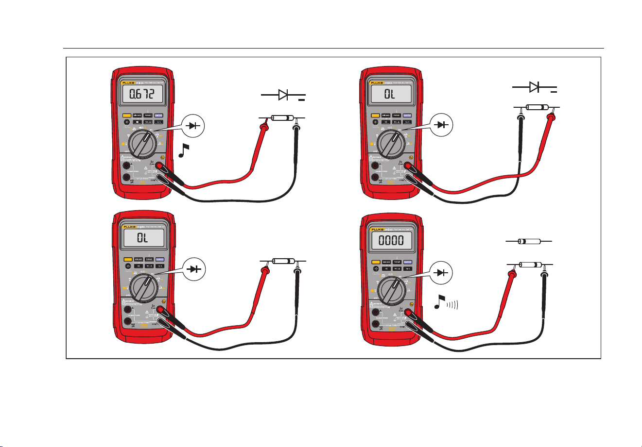
Use the diode test to examine diodes, transistors, silicon
controlled rectifiers (SCRs), and other semiconductor
devices. This test sends current through a semiconductor
junction, while it measures the junction's voltage drop. A
good silicon junction drops between 0.5 V and 0.8 V.
To do an out of circuit diode test, set up the Product as
shown in Figure 7. For forward-bias measurements on a
semiconductor component, put the red test lead on the
component's positive terminal and put the black lead on
the component's negative terminal.
In a circuit, a good diode will cause a forward-bias
measurement of 0.5 V to 0.8 V. A reverse-bias
measurement can be different because of the resistance
of other pathways between the probe tips.
A short beep sounds if the diode is good (<0.85 V). A
continuous beep sounds if the measurement is ≤0.100 V.
This measurement shows a short circuit. The display
shows “OL” if the diode is open.
1.888.610.7664 sales@GlobalTestSupply.com
Fluke-Direct.com
True-rms Digital Multimeter
How to Make Measurements
27
Bad Diode
+
+
Typical
Reading
Forward Bias
Reverse Bias
Bad Diode
Open
Shorted
Single Beep
or
grt06.eps
Figure 7. Diode Tests
1.888.610.7664 sales@GlobalTestSupply.com
Fluke-Direct.com

28 II Ex
Users Manual
28
AC or DC Current Measurements
XWWarning
To prevent electric shock or personal injury,
do not try an in-circuit current measurement
where the open-circuit potential to earth is
larger than 1000 V. You can cause Product
damage or personal injury if the fuse blows.
WCaution
To prevent damage to the Product or to the
equipment under test:
• Examine the fuses of the Product before
you measure current.
• Use the correct terminals, function, and
range for all measurements.
• Do not put the probes across (in parallel
with) a circuit or component when the
leads are connected to the current
terminals.
To measure current, you must open the current path of
the circuit under test and put the Product in series with
the circuit.
The current ranges of the Product are 600.0 μA, 6000 μA,
60.00 mA, 400.0 mA, 6.000 A, and 10.00 A.
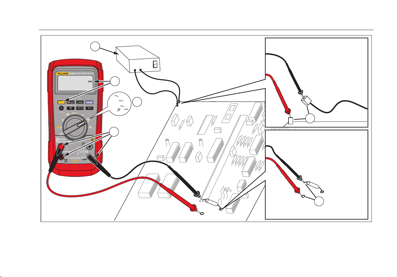
To measure current, refer to Figure 8 and continue as
follows:
1. Remove power from the circuit. Discharge all high-
voltage capacitors.
2. Put the black lead into the COM terminal. For
currents between 0 mA and 400 mA, put the red lead
into the mA/μA terminal. For currents more than
400 mA, put the red lead into the A terminal.
Note
To prevent damage to the 400-mA fuse of the Product,
use the mA/μA terminal only if you are sure the current is
less than 400 mA continuously or less than 600 mA for
18 hours or less.
1.888.610.7664 sales@GlobalTestSupply.com
Fluke-Direct.com
True-rms Digital Multimeter
How to Make Measurements
29
5
5
Circuit Power:
OFF to connect meter.
ON for measurement.
OFF to disconnect meter.
Current Through One Component
Total Current to Circuit
3
1
mA
A
A
4
2
grt07.eps
Figure 8. Current Measurements
1.888.610.7664 sales@GlobalTestSupply.com
Fluke-Direct.com

28 II Ex
Users Manual
30
3. If you use the A terminal, set the rotary switch to
mA/A. If you use the mA/μA terminal, set the rotary
switch to for currents below 6000 μA (6 mA), or
P for currents above 6000 μA.
4. To measure dc current, push .
5. Open the test circuit path. Touch the black probe to
the more negative side of the break. Touch the red
probe to the more positive side of the break. If the
leads are reversed, the measurement will be
negative, but will not cause Product damage.
6. Apply power to the circuit and then read the display.
Be sure to note the unit given at the right side of the
display (μA, mA, or A).
7. Remove power from the circuit and discharge all
high-voltage capacitors. Remove the Product and
restore the circuit to normal operation.
Some guidelines for current measurements are:
• If the current measurement is 0 A and you are sure
the Product is set up correctly, do a fuse test. See
the "Fuse Test" section.
• A current meter drops a small voltage across itself,
which could change circuit operation. You can
calculate this burden voltage with the values shown
in the specifications.
1.888.610.7664 sales@GlobalTestSupply.com
Fluke-Direct.com

True-rms Digital Multimeter
How to Make Measurements
31
Frequency Measurements
For frequency measurements, the Product counts the
number of times the signal crosses a set voltage level
each second.
Table 7 summarizes the trigger levels and applications for
frequency measurements in the ranges of the voltage and
current functions of the Product.
To measure frequency, connect the Product to the signal
source. Next push
G. When you push E, the
trigger slope switches between + and -, as shown by the
symbol at the left side of the display (refer to Figure 9
under "Duty Cycle"). Push
D to stop and start the
counter.
The Product autoranges to one of five frequency ranges:
199.99 Hz, 1999.9 Hz, 19.999 kHz, 199.99 kHz, and
>200 kHz. For frequencies less than 10 Hz, the display is
updated at the frequency of the input. Less than 0.5 Hz,
the display can be unstable.
Some guidelines for frequency measurements are:
• If a measurement shows as 0 Hz or is unstable, the
input signal can be below or near the trigger level. To
correct these problems, go to a lower range, which
increases the sensitivity of the Product. In the L
function, the lower ranges also have lower trigger
levels.
If a measurement is a multiple of what you expect, the
input signal can be distorted. Distortion can cause
multiple triggers of the frequency counter. Select a higher
voltage range to decrease Product sensitivity to try and
repair this problem. You can also set a dc range to
increase the trigger level as a possible solution. In
general, the lowest frequency shown in the display is the
correct one.
1.888.610.7664 sales@GlobalTestSupply.com
Fluke-Direct.com
28 II Ex
Users Manual
32
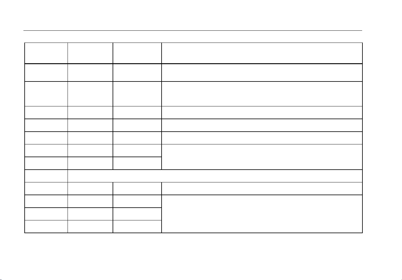
Table 7. Functions and Trigger Levels for Frequency Measurements
Function Range
Approximate
Trigger Level
Typical Application
6 V, 60 V,
600 V, 1000 V
±5 % of scale Most signals.
600 mV ±30 mV High-frequency 5 V logic signals. (The dc-coupling of the L function can
attenuate high-frequency logic signals, reducing their amplitude enough to
interfere with triggering.)
600 mV 40 mV Refer to the measurement guidelines given before this table.
V
6 V 1.7 V 5 V logic signals (TTL).
V
60 V 4 V Automotive switching signals.
V
600 V 40 V Refer to the measurement guidelines given before this table.
V
1000 V 100 V
Frequency counter characteristics are not available or specified for these functions.
All ranges ±5 % of scale AC current signals.
μA
600 μA, 6000 μA 30 μA , 300 μA Refer to the measurement guidelines given before this table.
60 mA, 400 mA 3.0 mA , 30 mA
A 6 A, 10 A .30 A, 3.0 A
1.888.610.7664 sales@GlobalTestSupply.com
Fluke-Direct.com
True-rms Digital Multimeter
How to Make Measurements
33
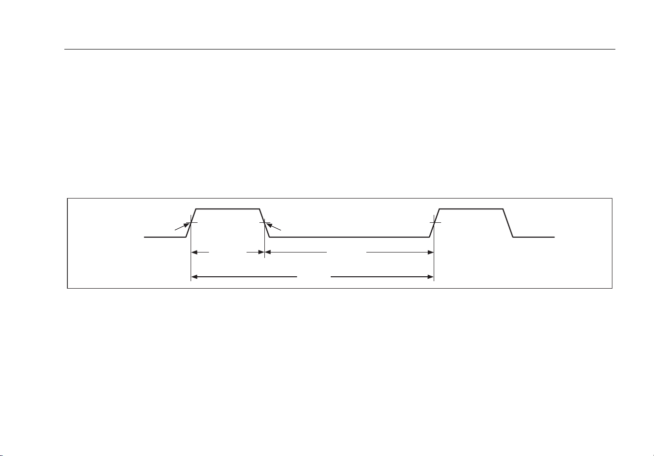
Duty Cycle Measurements
Duty cycle (or duty factor) is the percentage of time a
signal is above or below a trigger level in one cycle
(Figure 9). The duty cycle mode is optimized to measure
the on or off time of logic and switching signals. Systems
such as electronic fuel injection systems and switching
power supplies are controlled by pulses that have
different widths, which can be measured by a duty cycle
measurement.
To measure duty cycle, set up the Product to measure
frequency. Then push G a second time. As with the
frequency function, Push E to change the slope for
the counter.
For 5-V logic signals, use the 6-V dc range. For 12-V
switching signals in automobiles, use the 60 V dc range.
For sine waves, use the lowest range that does not result
in multiple triggers. (Normally, a distortion-free signal can
be up to ten times the amplitude of the selected voltage
range.)
If a duty cycle measurement is unstable, push MIN MAX;
then scroll to the AVG (average) display.
-Slope
Trigger Point
+Slope
Trigger Point
30% Above
+Slope
70% Below
-Slope
100%
iyf.eps
Figure 9. Components of Duty Cycle Measurements
1.888.610.7664 sales@GlobalTestSupply.com
Fluke-Direct.com

28 II Ex
Users Manual
34
How to Determine Pulse Width
For a periodic waveform (its pattern repeats at equal time
intervals), you can find the time that the signal is high or
low as follows:
1. Measure the signal's frequency.
2. Push G a second time to measure the signal's
duty cycle. Push E to select a measurement of
the signal's positive or negative pulse, refer to
Figure 9.
3. Use this formula to find the pulse width:
Pulse Width
=
% Duty Cycle ÷ 100
(in seconds) Frequency
HiRes Mode
On the Product, push H for one second to enter the high-
resolution (HiRes) 4-1/2 digit mode. Measurements are
shown at 10 times the usual resolution with a maximum
display of 19,999 counts. The HiRes mode works in all
modes but capacitance, frequency counter functions,
temperature, and the 250 μs (peak) MIN MAX modes.
To go to to the 3-1/2 digit mode, push H for one second.
1.888.610.7664 sales@GlobalTestSupply.com
Fluke-Direct.com

True-rms Digital Multimeter
MIN MAX Recording Mode
35
MIN MAX Recording Mode
The MIN MAX mode records minimum and maximum
input values. When the inputs go below the recorded
minimum value or above the recorded maximum value,
the Product beeps and records the new value. This mode
can be used to record intermittent measurements, record
maximum measurements while you are away or record
measurements while you operate the equipment under
test and cannot look at the Product. MIN MAX mode can
also calculate an average of all measurements since the
MIN MAX mode was started. To use MIN MAX mode,
refer to the functions in Table 8.
Response time is the length of time an input must stay at
a new value to be recorded. A shorter response time
records shorter events, but with decreased accuracy. All
recorded measurements are erased when you change
the response time. The Product has 100 millisecond and
250 μs (peak) response times. The 250 μs response time
is indicated by “” on the display.
The 100 millisecond response time is best for power
supply surges, inrush currents, and intermittents.
The average value (AVG) shown in the display is the
mathematical integral of all measurements since the start
of recording (overloads are discarded). The average
value is useful to smooth out unstable inputs, calculate
power consumption, or to get a percentage of time
estimate on how long a circuit is on.
Min Max records the signal extremes that are longer than
100 ms.
Peak records the signal extremes that are longer than
250 μs.
Smooth Feature (Power Up Option Only)
When the input signal changes quickly, “smoothing” gives
a more stable measurement on the display.
To use the smooth feature:
1. Hold down C while you turn the Product on. The
display shows “'---” until C is released.
2. The Smoothing icon () will appear on the left side
of the display to let you know that smoothing is on.
1.888.610.7664 sales@GlobalTestSupply.com
Fluke-Direct.com

28 II Ex
Users Manual
36
Table 8. MIN MAX Functions
Button MIN MAX Function
Enter MIN MAX recording mode. The Product is locked in the range shown before you
started MIN MAX mode. (Set the measurement function and range before you enter MIN
MAX.) The Product beeps each time a new minimum or maximum value is recorded.
(while in MIN MAX mode)
Step through maximum (MAX), minimum (MIN), average (AVG) and current values.
E
PEAK MIN MAX
Select 100 ms or 250 μs response time. (The 250 μs response time is shown by
on the display.) Stored values are erased. The current and AVG (average) values are not
available when 250 μs is selected.
D Stop recording. Stored values are not erased. Push again to continue recording.
(hold for 1 second)
Exit MIN MAX mode. Stored values are erased. The Product stays in the selected range.
1.888.610.7664 sales@GlobalTestSupply.com
Fluke-Direct.com

True-rms Digital Multimeter
AutoHOLD Mode
37
AutoHOLD
Mode
XWWarning
To prevent electrical shock or personal
injury, do not use AutoHOLD mode to see if
circuits are without power. The AutoHOLD
mode will not hold on unstable or noisy
measurements.
The AutoHOLD mode locks the current measurement on
the display. When a new, stable measurement is sensed,
the Product beeps and shows the new measurement. To
start or exit AutoHOLD mode, push D.
Relative Mode
When you set relative mode (F),the Product zeros
the display and stores the current measurement as the
reference for subsequent measurements. The Product is
locked into the range selected when you pushed
F.
Push F again to exit this mode.
In relative mode, the measurement shown is always the
difference between the current measurement and the
stored reference value. For example, if the stored
reference value is 15.00 V and the current measurement
is 14.10 V, the display shows -0.90 V.
1.888.610.7664 sales@GlobalTestSupply.com
Fluke-Direct.com

28 II Ex
Users Manual
38
Maintenance
XWWarning
To prevent electrical shock or personal
injury, have the Product repaired by ECOM
Instruments GmbH or an ECOM authorized
service center to keep Product certification.
General Maintenance
To clean the external surfaces of the Product, wipe the
case with a damp cloth and mild detergent. Do not use
abrasives or solvents.
Dirt or moisture in the terminals can cause incorrect
measurements and can falsely set off the Input Alert
feature. Clean the terminals as follows:
1. Turn the Product off and remove all test leads.
2. Shake out dirt that can be in the terminals.
3. Soak a clean swab with mild detergent and water.
Move the swab around in each terminal. Dry each
terminal with canned air to push the water and
detergent out of the terminals.
It is recommended that the Product be calibrated by Fluke
in two-year intervals.
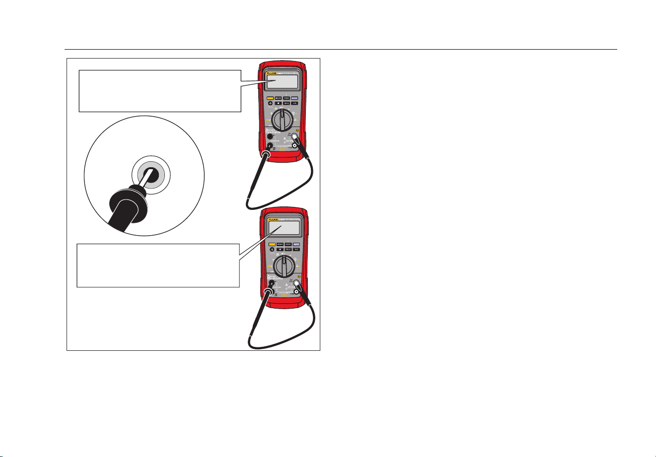
Fuse Test
As shown in Figure 10, with the Product in the N
function, put a test lead into the jack and place the
probe tip on the other end of the test lead against the
metal of the current input jack. If “LEAd” appears in the
display, the probe tip has been inserted too far into the
amps input jack. Lift the lead out a bit until the message
no longer shows in the display and OL or a resistance
measurement shows in the display. The resistance value
must be as shown in Figure 10. If the tests give
measurements other than those shown, have the Product
serviced.
XWWarning
To prevent electric shock or personal injury,
remove the test leads and all input signals
before you replace the batteries or fuses. To
prevent damage or injury, install ONLY
specified replacement fuses with the
amperage, voltage, and speed ratings shown
in Table 10.
1.888.610.7664 sales@GlobalTestSupply.com
Fluke-Direct.com
True-rms Digital Multimeter
Maintenance
39
Touch top half
of input contacts
Good 11 A fuse: 0.0 Ω to
0.5 Ω
Replace fuse: OL
Good 0.44 A fuse: 0.995 kΩ to
1.005 kΩ
Replace fuse: OL
grt08.eps
Figure 10. Current Fuse Test
How to Replace the Batteries
Replace the batteries with three AAA
batteries (NEDA 24A IEC LR03).
XWWarning
To prevent electrical shock or personal
injury:
• Replace the batteries when the low
battery indicator () shows to prevent
incorrect measurements. If the display
shows “batt” the Product will not
function until the batteries are replaced.
• Use only three AAA 1.5-volt batteries,
correctly installed to power the Product.
See the table on the subsequent page for
a list of approved batteries. All cells are
to be replaced at the same time with
same part number cells in fresh air
locations only.
1.888.610.7664 sales@GlobalTestSupply.com
Fluke-Direct.com

28 II Ex
Users Manual
40
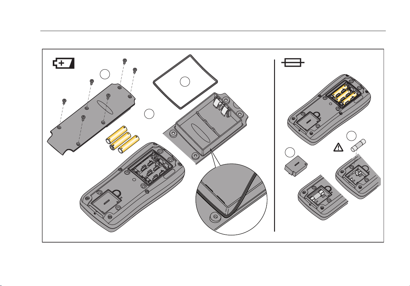
Replace the batteries as follows, refer to Figure 11:
1. Turn the rotary switch to OFF and remove the test
leads from the terminals.
2. Remove the six Torx-head screws from the case
bottom and remove the battery door ().
Note
When you lift the battery door, make sure the
rubber gasket stays attached to the battery
compartment barrier.
3. Remove the three batteries and replace all three with
AAA Alkaline batteries ().
4. Make sure the battery compartment gasket () is
properly installed around the outside edge of the
battery compartment barrier.
5. Align the battery compartment barrier with battery
compartment while you replace the battery door.
6. Attach the door with the six Torx-head screws.
Note
It is recommended the batteries be removed
from the Product for long periods of storage.
Table 9. Approved Batteries
Battery Description Manufacturer
Duracell Procell MN2400 LR03
Duracell
Duracell Plus MN2400 LR03
Max Tech No. 4703
Varta
Industrial Alcaline No. 4003
[1]
Eveready Energizer No. E92 Eveready
Rayovac Alkaline AAA (U.S.
Type)
Rayovac
Panasonic LR03XWA Panasonic
[1] Minimum operating temperature is -10 °C.
1.888.610.7664 sales@GlobalTestSupply.com
Fluke-Direct.com
True-rms Digital Multimeter
Maintenance
41
1
4
5
2
3
grt10.eps
Figure 11. Battery and Fuse Replacement
1.888.610.7664 sales@GlobalTestSupply.com
Fluke-Direct.com

28 II Ex
Users Manual
42
How to Replace the Fuses
Examine or replace the fuses in the Product as follows
(See Figure 11):
1. Turn the rotary switch to OFF and remove the test
leads from the terminals
2. Refer to step 2 in the “How to Replace the Batteries”
section above to remove the battery door.
3. Carefully lift out the fuse assembly () from the fuse
compartment.
4. Remove the 11 A fuse by carefully prying one end
loose, then lift the fuse out of its bracket ().
5. Install ONLY specified replacement fuses with the
amperage, voltage, and speed ratings shown in
Table 10. The 440-mA fuse is attached to the fuse
assembly. You must use a new fuse assembly to
replace the 440 mA fuse.
6. Install the fuse assembly into the fuse compartment.
7. Refer to steps four through six in the “How to
Replace the Batteries” section above to replace the
battery door.
Service and Parts
If the Product fails, examine the batteries and fuses.
Refer to this manual to make sure the Product is used
correctly.
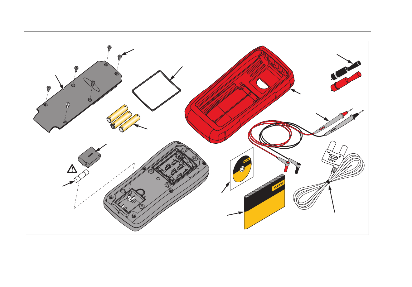
Replacement parts and accessories are shown in
Table 10 and Figure 12.
To order parts and accessories, refer to the “How to
Contact Fluke” section.
1.888.610.7664 sales@GlobalTestSupply.com
Fluke-Direct.com

True-rms Digital Multimeter
Service and Parts
43
Table 10. Replacement Parts
Description Qty.
Fluke Part or Model
Number
Battery, AAA 1.5 V 3
2838018
Fuse, 11 A, 1000 V, FAST 1
803293
Screw 6
3861068
Gasket, Battery Door 1
3439087
28 II Ex Fuse Assembly 1
4016494
28 II Ex Holster 1
4013542
28 II Ex Battery Door Assembly 1
4093984
Alligator Clip, Black 1
AC172
Alligator Clip, Red 1
Test Lead Set 1
TL175
Integrated DMM Temperature Probe 1
80BK-A
28 II Ex Users Manual CD 1
3945765
28 II Ex Getting Started Manual 1
3945752
W To ensure safety, use exact replacement only.
1.888.610.7664 sales@GlobalTestSupply.com
Fluke-Direct.com
28 II Ex
Users Manual
44
AC172
Alligator Clips
28 II Ex Holster
28 II Ex
Getting Started Manual
Battery Door
Gasket
Screw
Battery
AAA 1.5 V
Fuse Assembly
*
Contains 440 mA
Fuse
28 II Ex
Users Manual CD
Battery
Door
Fuse
11 A,
1000 V, Fast
TL175
Test Lead Set
80BK-A Integrated DMM
Temperature Probe
grt11.eps
Figure 12. Replacement Parts
1.888.610.7664 sales@GlobalTestSupply.com
Fluke-Direct.com

True-rms Digital Multimeter
Service and Parts
45
Table 11. Accessories
Item Description
AC172 Alligator Clips
80BK-A Bead Temperature Probe
TPAK ToolPak Magnetic Hanger
TL175 Silicone test lead set with probes
I400 W AC Current Clamp
[1]
80PK-27 W Temperature Probe
[2]
All accessories in this table are approved for use in explosive hazardous environments. Fluke accessories are available from an authorized Fluke distributor.
[1] W Warning - To prevent personal injury or property damage, do not use this accessory in hazardous areas where dust is moved, transported, or
conveyed.
[2] W Warning - To prevent personal injury or property damage, do not use this accessory in dust hazardous areas.
1.888.610.7664 sales@GlobalTestSupply.com
Fluke-Direct.com

28 II Ex
Users Manual
46
General Specifications
Maximum voltage between any
terminal and earth ground ........................................... 1000 V rms
W Fuse for mA inputs .................................................. 440 mA, 1000 V FAST Fuse
W Fuse for A inputs ..................................................... 11 A, 1000 V FAST Fuse
Display ........................................................................... 6000 counts, updates 4/sec (19,999 counts in high-resolution mode).
Altitude
Operating .................................................................... 2,000 meters
Storage ....................................................................... 10,000 meters
Temperature
Operating .................................................................... -15 °C to 50 °C
Storage ....................................................................... -55 °C to +85 °C (without battery)
-55 °C to +60 °C (with battery)
Temperature coefficient ............................................... 0.05 X (specified accuracy) / °C (<18 °C or >28 °C)
1.888.610.7664 sales@GlobalTestSupply.com
Fluke-Direct.com

True-rms Digital Multimeter
General Specifications
47
Electromagnetic Compatibility (EN 61326-1:2005) ..... In an RF field of 3 V/M, accuracy = specified accuracy +20 counts, except 600 μA dc
range total accuracy = specified accuracy +60 counts. Temperature not specified
Relative Humidity .......................................................... 0 % to 80 % (0 °C to 35 °C)
0 % to 70 % (35 °C to 50 °C)
Battery Type ................................................................... 3 AAA Alkaline batteries, NEDA 24A IEC LR03
Approved Batteries ....................................................... Duracell Procell MN2400 LR03
Duracell Plus MN2400 LR03
Varta Max Tech No. 4703
Varta Industrial Alcaline No. 4003 (min. operating temperature is -10 °C)
Eveready Energizer No. E92
Rayovac Alkaline AAA (U.S. Type)
Panasonic LR03XWA
Battery Life ..................................................................... 400 hrs typical without backlight (Alkaline)
Vibration ......................................................................... Per MIL-PRF-28800 for a Class 2 instrument
Shock .............................................................................. 1 Meter drop per IEC 61010 (3 Meter drop with holster)
Size (H x W x L) .............................................................. 4.57 cm x 10.0 cm x 21.33 cm (1.80 in x 3.95 in x 8.40 in)
Size with Holster ............................................................ 6.35 cm x 10.0 cm x 19.81 cm (2.50 in x 3.95 in x 7.80 in)
Weight ............................................................................ 567.8 g (1.25 lb)
Weight with Holster and Flex-Stand ............................ 769.8 g (1.70 lb)
Safety Compliance ........................................................ Complies with ANSI/ISA S82.01-2004, CAN/CSA C22.2 61010-1-04 to 600 V
Measurement Category IV. Licensed by TÜV to EN61010-1, Pollution degree 2
Certifications ................................................................. CSA, TÜV, P,
, GOST, ATEX, IECEx
IP Rating ......................................................................... 67 (Non-operating. Protected against dust and the effect of immersion up to 1 m for
30 min.)
1.888.610.7664 sales@GlobalTestSupply.com
Fluke-Direct.com
28 II Ex
Users Manual
48
Detailed Specifications
For all detailed specifications:
Accuracy is specified for 2 years after calibration, at operating temperatures of 18 °C to 28 °C, with relative humidity at 0 % to 80 %.
Accuracy specifications take the form of ±([% of Reading] + [Number of least-significant digits]). In the 4 ½-digit mode, multiply the number of
least-significant digits (counts) by 10.
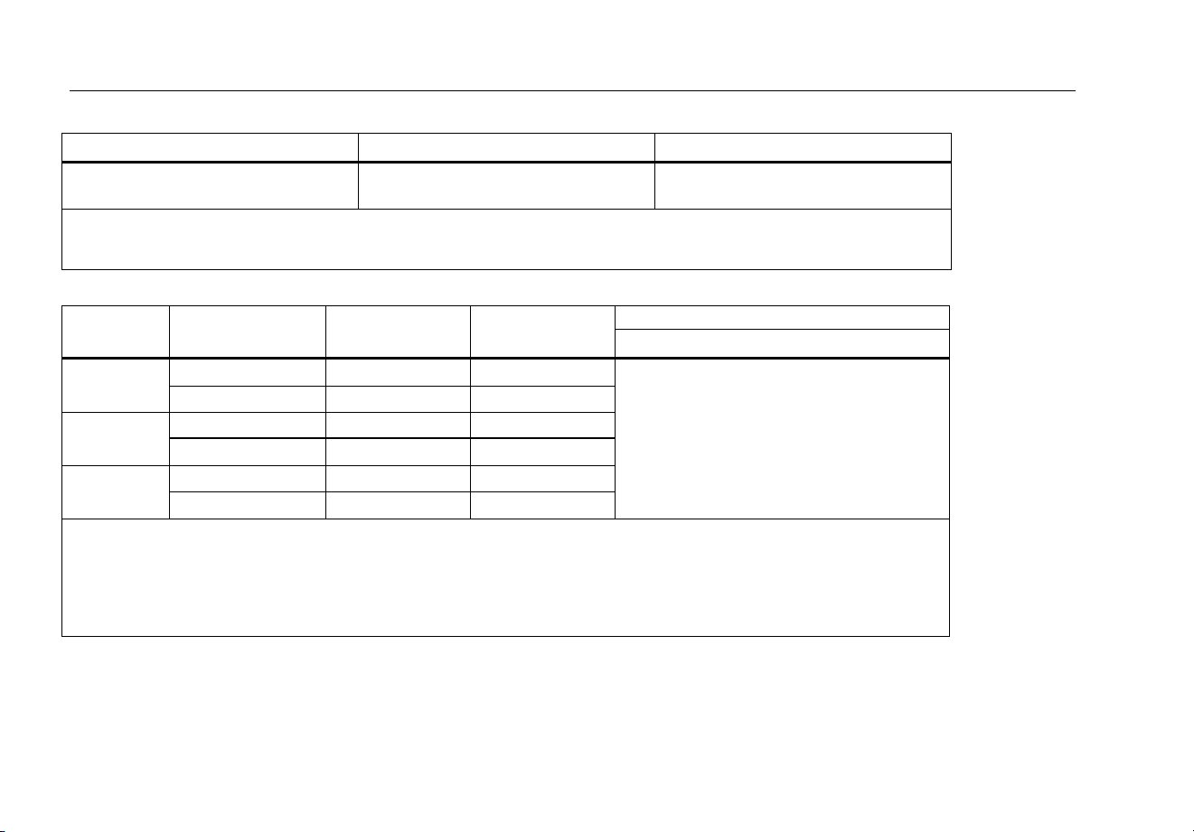
AC Voltage
AC conversions are ac-coupled and valid from 3 % to 100 % of range.
Range Resolution
Accuracy
45 – 65 Hz 30 – 200 Hz 200 – 440 Hz 440 Hz – 1 kHz 1 – 5 kHz 5 – 20 kHz
600.0 mV 0.1 mV
±(0.7 % + 4)
±(1.0 % + 4)
±(2 % + 4)
±(2 % + 20)
[1]
6.000 V 0.001 V
60.00 V 0.01 V
±(0.7 % + 2)
±(2 % + 4)
[2]
Unspecified
600.0 V 0.1 V Unspecified
1000 V 1 V Unspecified Unspecified
Low-Pass Filter
±(1.0 % + 4)
[1]
+1.0 % + 4
-6.0 % - 4
[3]
Unspecified Unspecified Unspecified
[1] Below 10 % of range, add 12 counts.
[2] Frequency range: 1 kHz to 2.5 kHz
[3] Specification increases from -1 % to -6 % at 440 Hz when filter is used.
1.888.610.7664 sales@GlobalTestSupply.com
Fluke-Direct.com

True-rms Digital Multimeter
Detailed Specifications
49
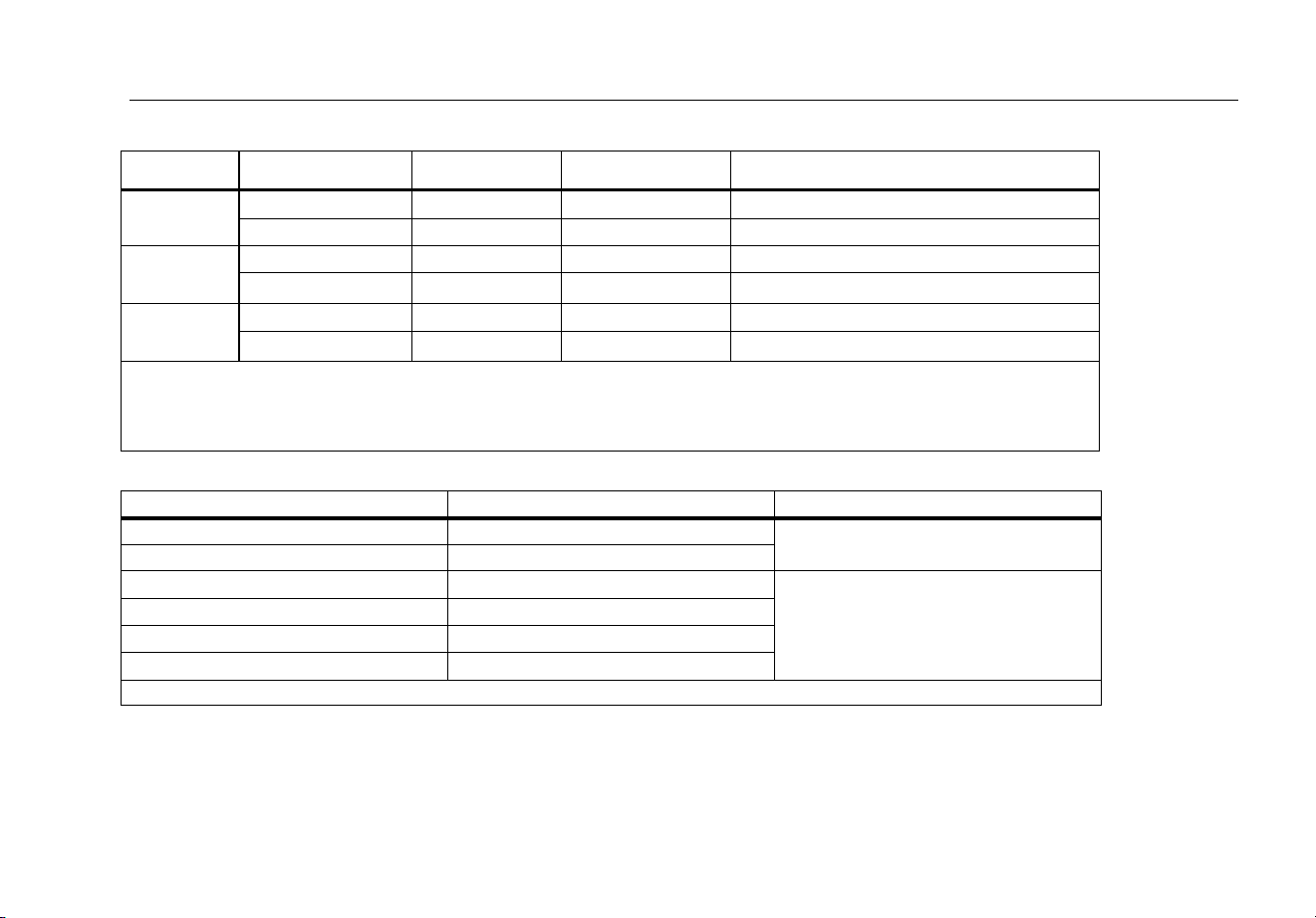
DC Voltage, Conductance, and Resistance
Function Range Resolution Accuracy
mV dc 600.0 mV 0.1 mV
±(0.1 % + 1)
V dc
6.000 V 0.001 V
±(0.05 % + 1)
60.00 V 0.01 V
600.0 V 0.1 V
1000 V 1 V
Ω
600.0 Ω 0.1 Ω
±(0.2 % + 2)
[2]
6.000 kΩ 0.001 kΩ
±(0.2 % + 1)
60.00 kΩ 0.01 kΩ
600.0 kΩ 0.1 kΩ
±(0.6 % + 1)
6.000 MΩ 0.001 MΩ
50.00 MΩ 0.01 MΩ
±(1.0 % + 3)
[1,3]
nS
60.00 nS 0.01 nS
±(1.0 % + 10)
[1,2,3]
[1] Add 0.5 % of reading when measuring above 30 MΩ in the 50 MΩ range, and 20 counts below 33 nS in the 60 nS range.
[2] When using the rel function to compensate for offsets.
[3] >40 °C temperature coefficient is 0.1 x (specified accuracy)/°C.
1.888.610.7664 sales@GlobalTestSupply.com
Fluke-Direct.com
28 II Ex
Users Manual
50
Temperature
Range Resolution
Accuracy
[1,2]
-200 °C to +1090 °C
-328 °F to +1994 °F
0.1 °C
0.1 °F
±(1.0 % + 10)
±(1.0 % + 18)
[1] Does not include error of the thermocouple probe.
[2] Accuracy specification assumes ambient temperature stable to ± 1 °C. For ambient temperature changes of ± 5 °C, rated accuracy
applies after 2 hours.
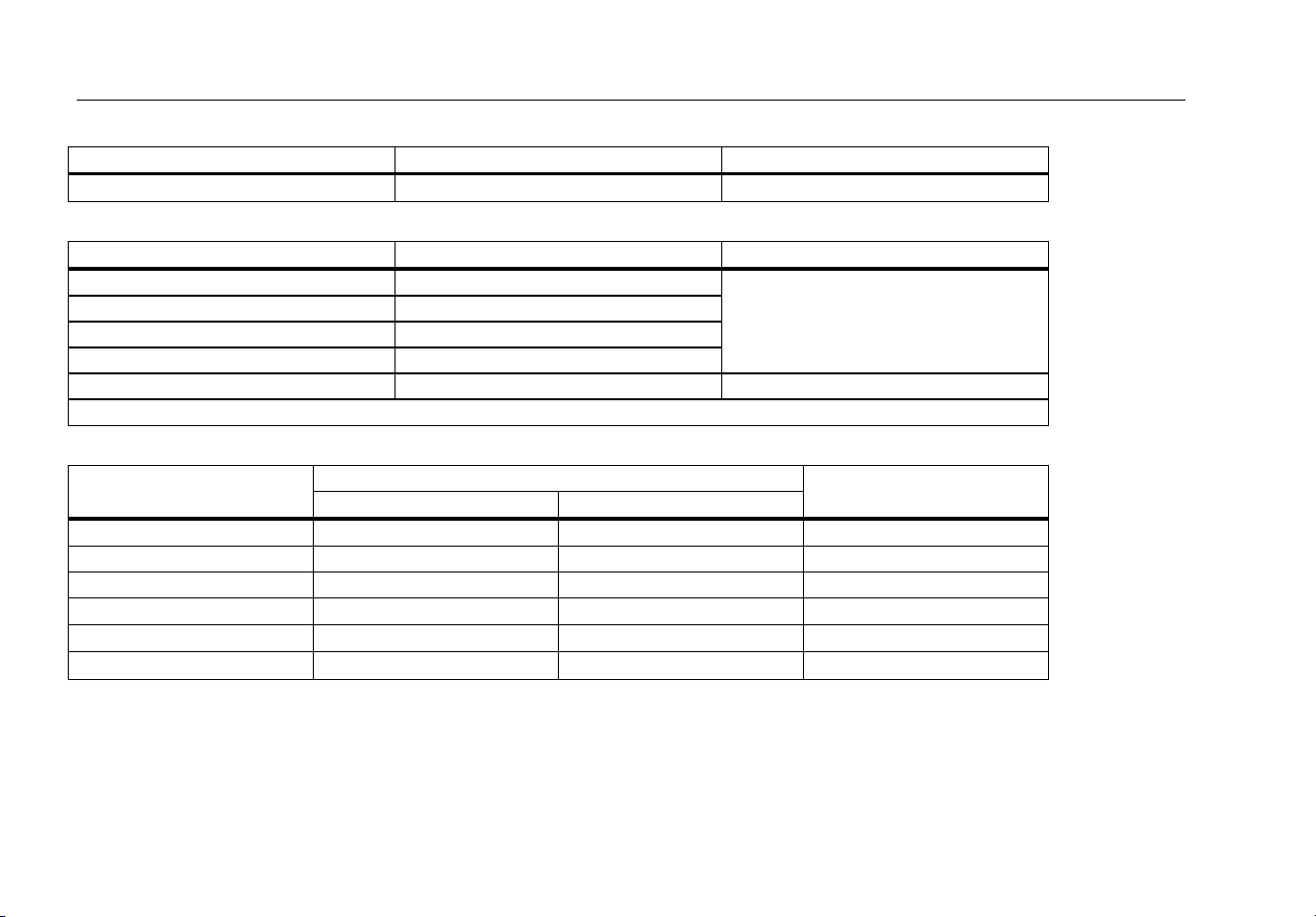
AC Current
Function Range Resolution Burden Voltage
Accuracy
(45 Hz – 2 kHz)
[1]
μA ac
600.0 μA 0.1 μA 100 μV/μA
±(1.0 % + 2)
6000 μA 1 μA 100 μV/μA
mA ac
60.00 mA 0.01 mA 1.8 mV/mA
400.0 mA
[2]
0.1 mA 1.8 mV/mA
A ac
6.000 A 0.001 A 0.03 V/A
10.00 A
[3,4]
0.01 A 0.03 V/A
[1] AC conversions are ac coupled, true rms responding, and valid from 3 % to 100 % of range, except 400 mA range. (5 % to 100 %
of range) and 10 A range (15 % to 100 % or range).
[2] 400 mA continuous. 600 mA for 18 hr maximum.
[3] W 10 A continuous up to 35 °C. <20 minutes on, 5 minutes off at 35 °C to 55 °C. >10 A to 20 A for 30 seconds maximum, 5 minutes
off.
[4] >10 A accuracy unspecified.
1.888.610.7664 sales@GlobalTestSupply.com
Fluke-Direct.com
True-rms Digital Multimeter
Detailed Specifications
51
DC Current
Function Range Resolution Burden Voltage Accuracy
μA dc
600.0 μA 0.1 μA 100 μV/μA ±(0.2 % + 4)
6000 μA 1 μA 100 μV/μA ±(0.2 % + 2)
mA dc
60.00 mA 0.01 mA 1.8 mV/mA
±(0.2 % + 4)
400.0 mA
[1]
0.1 mA 1.8 mV/mA
±(0.2 % + 2)
A dc
6.000 A 0.001 A 0.03 V/A
±(0.2 % + 4)
10.00 A
[2,3]
0.01 A 0.03 V/A
±(0.2 % + 2)
[1] 400 mA continuous; 600 mA for 18 hr maximum.
[2] W 10 A continuous up to 35 °C. <20 minutes on, 5 minutes off at 35 °C to 55 °C. >10 A to 20 A for 30 seconds maximum, 5 minutes
off.
[3] >10 A accuracy unspecified.
Capacitance
Range Resolution Accuracy
10.00 nF 0.01 nF
±(1.0 % + 2)
[1]
100.0 nF 0.1 nF
1.000 μF 0.001 μF
±(1.0 % + 2)
10.00 μF 0.01 μF
100.0 μF 0.1 μF
9999 μF 1 μF
[1] With a film capacitor or better, using the rel mode to zero residual.
1.888.610.7664 sales@GlobalTestSupply.com
Fluke-Direct.com
28 II Ex
Users Manual
52
Diode
Range Resolution Accuracy
2.000 V 0.001 V
±(2.0 % + 1)
Frequency
Range Resolution Accuracy
199.99 Hz 0.01 Hz
±(0.005 % + 1)
[1]
1999.9 Hz 0.1 Hz
19.999 kHz 0.001 kHz
199.99 kHz 0.01 kHz
>200 kHz 0.1 kHz Unspecified
[1] From 0.5 Hz to 200 kHz and for pulse widths > 2 μs.
Frequency Counter Sensitivity and Trigger Levels
Input Range
Minimum Sensitivity (RMS Sine Wave)
Approximate Trigger Level
(DC Voltage Function)
5 Hz – 20 kHz 0.5 Hz – 200 kHz
600 mV dc 70 mV (to 400 Hz) 70 mV (to 400 Hz) 40 mV
600 mV ac 150 mV 150 mV -
6 V 0.3 V 0.7 V 1.7 V
60 V 3 V
7 V (≤140 kHz)
4 V
600 V 30 V
70 V (≤14.0 kHz)
40 V
1000 V 100 V
200 V (≤1.4 kHz)
100 V
1.888.610.7664 sales@GlobalTestSupply.com
Fluke-Direct.com
True-rms Digital Multimeter
Detailed Specifications
53
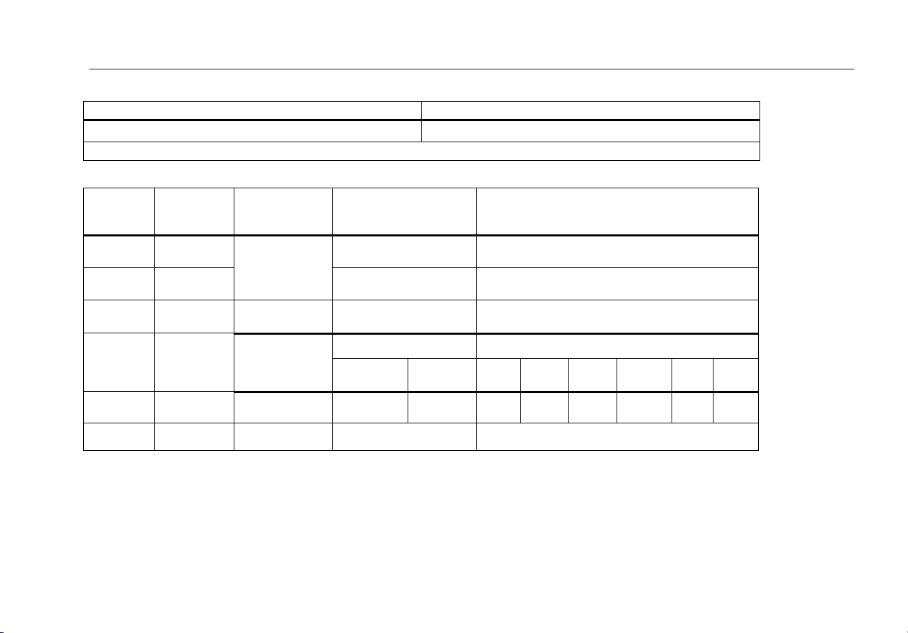
Duty Cycle (Vdc and mVdc)
Range Accuracy
0.0 % to 99.9 %
[1]
Within ± (0.2 % per kHz + 0.1 %) for rise times <1 μs.
[1] 0.5 Hz to 200 kHz, pulse width >2 μs. Pulse width range is determined by the frequency by the frequency of the signal.
Input Characteristics
Function
Overload
Protection
Input
Impedance
(nominal)
Common Mode
Rejection Ratio
(1 kΩ unbalance)
Normal Mode Rejection
L
1000 V rms
10 MΩ <100 pF
> 120 dB at dc, 50 Hz
or 60 Hz
> 60 dB at 50 Hz or 60 Hz
1000 V rms
> 120 dB at dc, 50 Hz
or 60 Hz
> 60 dB at 50 Hz or 60 Hz
K
1000 V rms
10 MΩ < 100 pF
(ac-coupled)
> 60 dB, dc to 60 Hz
Open Circuit
Test Voltage
Full Scale Voltage Typical Short Circuit Current
To 6 MΩ
5 MΩ or
60 nS
600 Ω 6 kΩ 60 kΩ 600 kΩ 6 MΩ 50 MΩ
Ω
1000 V rms <7.0 V dc <1.7 V dc <1.9 V dc
500 μA 100 μA 10 μA 1 μA 0.4 μA 0.2 μA
G
1000 V rms <7.0 V dc 2.200 V dc 1.0 mA typical
1.888.610.7664 sales@GlobalTestSupply.com
Fluke-Direct.com

28 II Ex
Users Manual
54
MIN MAX Recording
Nominal Response Accuracy
100 ms to 80 %
(dc functions)
Specified accuracy ±12 counts for changes >200 ms in duration
120 ms to 80 %
(ac functions)
Specified accuracy ±40 counts for changes >350 ms and inputs >25 % of range
250 μs (peak)
[1]
Specified accuracy ±100 counts for changes >250 μs in duration
(add ±100 counts for readings over 6000 counts)
(add ±100 counts for readings in Low Pass mode)
[1] For 6 V range: 1 ms
1.888.610.7664 sales@GlobalTestSupply.com
Fluke-Direct.com
