

About this Document
This manual is intended for administrators and users of the AXIS
Q7424–R Video Encoder, and is applicable to firmware 5.40 and later.
It includes instructions for using and managing the product on your
network. Previous experience of networking will be of use when using
this product. Some knowledge of UNIX or Linux-based systems may also
be beneficial, for developing shell scripts and applica tions. Later version
of this document will be posted to the Axis website, as required. See
also the product’s online help, available via the web-based interface.
Liability
Every care has been taken in the preparation of this manual. Please
inform your local Axis office of any inaccuracies or omissions. Axis
Communications AB cannot be held responsible for any technical or
typographical errors and reserves the right to make changes to the
product and manuals without prior notice. Axis Communications AB
makes no warranty of any kind with regard to the material contained
within this document, including, but not limited to, the implied
warranties of merchantability and fitness for a particular purpose. Axis
Communications AB shall not be liable nor responsible for incide ntal or
consequential damages in connection with the furnishing, performance
or use o f this material. This product is only to be us ed for its intended
purpose.
Intellectual Property Rights
Axis AB has int ellect ual property rights relating to technology embodied
in the product described in this document. In particular, and without
limitation, these intel lectual property rights ma y include on e or more
of the pa tents listed at http://www.axis.com/pa tent.htm and one or
more additional patents or pending pat ent applications in the US and
other countries.
This product contains licens ed third-party software. See the menu item
“About” in the p roduct’s user interface for more information.
This product contains source code copyright Apple Computer,
Inc.,underthetermsofApplePublicSourceLicense2.0(see
http://www.opensource.ap ple.com/apsl). The source code is available
from http ://developer.apple.com/darwin/projects/bonjou r/
Equipment M odifications
This equipm ent must be installed and used in strict accordance with the
instructions given in the user documentation. This equipment contains
no user-serviceable components. Unauthorized equ ipment ch anges or
modifications will invalidate all applicab le regulatory certifications
and approvals.
Trademark Acknowledgments
Apple, Boa, Bonjour, Ethernet, Internet Explorer, Linux, Microsoft,
Mozilla, Real, SMPTE, QuickTime, UNIX, Windows, Windows Vista and
WWW are registered trademarks of the respective holders. Java and
all Java-based trademarks and logos are trademarks or registered
trademarks of Oracle and/or its affiliates. UPnP
TM
is a certific
ation
mark of the UPnP
TM
Implementers Corporation.
Support
Should you require any technical assistance
,pleasecontactyourAxis
reseller. If your questions cannot be answered immediately, your
reseller will forward your queries through the appropriate channels to
ensure a rapid response. If you are connec
tedtotheInternet,youcan:
• download user documentation and software u pdates
• find answers to resolved problems in the FAQ database. Search
by product, category, or phrase
• report problems to Axis support staff by logging in to your private
support area
• chat with Axis support staff (se lected countries only)
• visit Axis Support at www.axis.co m/techsup/
Electromagnetic C om patibility (EMC)
This equipment has been designed and tested to fulfill applicab le
standards for:
• Radio frequency em ission when install ed according to the
instructions and used
in its intended environment.
• Immunity to electrical and electromagnetic phenomena when
installed according to the instruction s and used in its intended
environment.
USA
This equipm ent has been tested using a shielded network cab le (STP)
and found to com p ly with the limits for a Class B digital device,
pursuant to part 15 of the FCC Rules . These limits are designed
to provide reasonab le protection against harmful interfe rence in a
residential installation. This e quipment generates, uses and can radiate
radio frequency energy and, if not installed and used in accordance
with the instructions, m ay cause harmful i nterference to radio
communications. However, there is no guarantee that interference
will not occur in a particular installation. If this eq uipment does
cause harmful interference to radio or television reception, which
can be determined by turning the equipment off and on, the user is
encouraged to try to correct the interference by one or more of the
following measures:
• Reorient or relocate the receiving antenna.
• Increase the separation b etween the equipment and receiver.
• Connect the equipment into an outlet on a circuit different from
that to wh ich the receiver is connected.
• Consult the dealer or an experienced radio/TV technician for help
Canada
This Class B digital apparatus complies with Ca na d ian ICES-003.
Europe
This digital equipment fulfills the requireme nts fo r RF emission
according to the Class B limit of EN 55022.
This product fulfills the requirements for emission s and immunity
according to EN 50121-4 railway applications.
This product fulfills the requirements for immunity according to
EN 61000-6-1 residential, commercial and light-industry environments.
This product fulfills the requirements for immunity according to
EN 61000-6-2 industrial environments.
This product fulfills the requirements for immunity according to
EN 55024 office and commercial e nviron m ents.
Australia/New Zealand
This digital equipme nt fulfills the requirement s for RF emission
according to the C las s B limit of AS/N ZS CISPR 22.
Korea
이 기기는 가정용(B급) 전자파적합기기로서 주로 가정에서 사
용하는것을목적으로하며, 모든 지역에서 사용할 수 있습니다.
Japan
この装置は、クラスB 情報技術装置です。この装置は、家庭
環境で使用することを目 的としていますが、この装置がラジ
オやテレビジョン受信機に近接して使用されると、 受信障
害を引き起こすことがあります。 取扱説明書に従って正し
い取り扱いをして下さい。

AXIS Q7424–R
Table of Contents
HardwareOverview .......................................... 5
Connectors .................................................... 5
LEDIndicators .................................................. 6
AccessingtheProduct ....................................... 7
AccessfromaBrowser ........................................... 7
AccessfromtheInternet .......................................... 8
SettheRootPassword ........................................... 8
TheLiveViewPage .............................................. 9
MediaStreams ............................................. 12
HowtoStreamH.264 ............................................ 12
MJPEG ........................................................ 12
AXISMediaControl(AMC) ........................................ 12
AlternativeMethodsofAccessingtheVideoStream .................... 13
AccessingAudioStreams ......................................... 14
SettingUptheProduct ...................................... 15
BasicSetup .................................................... 15
VideoandAudio ............................................ 16
VideoStream ................................................... 16
Quadstream ................................................... 17
Stream Pro fi les ................................................. 17
CameraSettings ................................................ 17
PrivacyMask ................................................... 18
Overlay ........................................................ 18
AudioSettings .................................................. 19
AudioClips .................................................... 21
Live View Config ............................................ 22
PTZ(PanTiltZoom) ......................................... 25
InstallingaPTZdriver ............................................ 25
PresetPositions ................................................. 25
GuardTour ..................................................... 26
Advanced ...................................................... 26
Applications ............................................... 28
Detectors .................................................. 29
CameraTampering .............................................. 29
MotionDetection ............................................... 29
AudioDetection ................................................ 30
Events .................................................... 31
SettingUpanActionRule ........................................ 32
Recipients ..................................................... 33
Schedules ...................................................... 33
Recurrenc
es ....................................................
33
Recordings ................................................. 35
RecordingList .................................................. 35
Continuousrecording ............................................ 35
SystemOptions ............................................. 37
Security ....................................................... 37
Date&Time .................................................... 38
Network ....................................................... 39
Storage ....................................................... 43
Ports&Devices ................................................. 44
Maintenance ................................................... 45
Support ....................................................... 46
Advanced ...................................................... 47
ResettoFactoryDefaultSettings ................................... 47
Troubleshooting ............................................ 48
CheckingtheFirmware ........................................... 48
UpgradingtheFirmware .......................................... 48
EmergencyRecoveryProcedure .................................... 48
Symptoms,PossibleCausesandRemedialActions ..................... 49
Technical Specifications ...................................... 53
Connectors .................................................... 55
3

AXIS Q7424–R
Hardware Overview
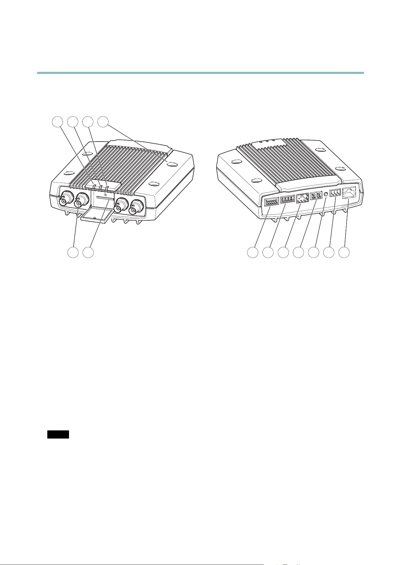
Hardware Overview
5 6 7 8 9
21 3 4
10 11 12 13
1.
LED i ndicator power
2.
LED i ndicator status
3.
LED ind icator network
4.
Mounting holes
5.
Video input connectors
6.
SD memory card slot
7.
I/O connector
8.
Audio connectors
9.
SFP co nnector
10.
RS-485/RS-422 connector
11.
Control button
12.
Power connector
13.
Network connector (PoE)
Connectors
For technical specifications, see
page 53
.
Network connector - RJ-45 Ethernet connector. Supports Power over Ethernet (PoE).
SFP connector - The unit can only use one Network interface, either an SFP module or RJ–45 connector. SFP module has higher
priority than the RJ–45 connector.
NOTICE
Due to local regulations or the environmental and electrical conditions in which the product is to be use d, a shielded
network cable (STP) may be appropriate or required. Any network cables that are routed in outdoor environments or similar
shall be shielded (STP) and intended for their specific use. Make sure that the network switch is properly grounded . See
Electromagnetic Compatibility (EMC )
for regulatory requirements.
Au
dio terminal connector - 4–pin terminal block for audio input and output.
SD card slot - A standard or high-capacity SD card (not includ ed) can be used for local recording with removable storage.
5

AXIS Q7424–R
Hardware Overview
NOTICE
To prevent corruption of recordings, the SD card should be unmounted before removal. To unmount, go to Setup > System
Options > Storage > SD Card a n d click Unmount.
Control button - The control button is used for:
• ConnectingtoanAXISVideoHostingSystemservice.See
page 40
. To connect, press and hold the button for about
1 second until the Status LED flashes green.
• ConnectingtoAXISInternetDynamicDNSService. See
page 40
. To connect, press and hold the button for
about 3 seconds.
• Resetting the p rod uct to fa ctory default settings. See
page 47
.
Power connector - 3-pin terminal blo ck for power input.
I/O terminal connector - Use in applica t ions for e .g . motion detection, event triggering, time lapse recording and alarm notifications.
In addition to an auxili ary pow e r and a GND pin, the I/O terminal connector provides the interface to:
• Digital output — For connecting external devices such as relays and LEDs. Connected devices can be activated by
the VAPIX® Application Programming Interface, output b uttons on the Live View page or by an Actio n Rule. The
output will show as active (shown under System Options > Ports & Devices) if the alarm device is activated.
• Digital input — A n alarm input for connecting devices tha t ca n toggle between an open and closed circuit, for
example: PIRs, door/window contacts, glass break detectors, etc. W hen a signal is received the state changes and
the input becomes active (shown under System Options > Ports & Devices).
RS-485/RS-422 connector - Two 2-pin terminal blocks for RS-485/RS-422 serial interface used to control auxiliary equipment,
e.g. PTZ devices.
LED Indicators
LED
Color
Indication
Green
Steady for connection to a 1 GBit/s network. Flashes for network activity.
Amber
Steady for connection to a 10/100 MBit/s network. Flashes for network activity.
Network
Unlit No network connection.
Green Steady g reen for normal operation.
Amber
Steady during startup and when restoring settings.
Status
Red
Slow flash for failed u
pgrade.
Green
Normal oper ation.
Power
Amber
Flashes green/amber during firmware upgrade.
Note
• The Status LED can be configured to flash while an ev ent is active.
• The S tatus LED can be configured to flash for identifying the unit. This can be done under Setup > System Options >
Maintenance.
6

AXIS Q7424–R
Accessing the Product
Accessing the Product
To install the Axis product, refer to the Installation Guide supplie d with the pro duct.
The product can be used with most operating systems and browsers. The recommended browsers are Interne t Explorer with Windows,
Safari with M acintosh and Firefox with other operating systems. See
Technical Specifications, on page 53
.Toviewstreamingvideoin
Internet Exp lore r, allow install ation of AX IS Media Control (AM C ) when prompted.
Note
• Q uickTime
TM
is also supported for viewing H.264 streams and for audio.
• If your computer restricts the use of additional software components, the product can be configured to use a Java
applet for viewing Motion JPEG.
Access from a Browser
1. Start a browser (Internet Explorer, Firefox, Safari).
2. Enter the IP address o r host name of the Axis product in the browser’s Location/Address field. To access the product from a
Macintosh computer (Mac OS X), click on the Bonjour tab and select the product from the drop-down list.
If you do not know the IP a ddress, use AXIS IP Utility to locate the product on the network. For more information on how to
discover and assign an IP ad dress, refer to the Installation Guide.
3. Enter your user name and p assword. If this is the first t im e the product is accessed , the root password must first be
configured; for instructions see
Set the Root Password, on page 8
.
4. The product’s Live View page appears in y our browser.
Note
The controls and layout of the Live View page may have been custom ized to me et specific installation requirements and
user preferences. Consequently, some of the examples and functions featured here may differ fro m those displayed in
your own Live Vie w page.
7
AXIS Q7424–R
Accessing the Product
Access from the Internet
Once connected, the Axis product is accessible on your local network (LAN). To access the p roduct from t
he Internet you must
configure your network router to allow incoming data traffic to the product. To do this, enable the NAT-travers al feature, which
will attempt to automatically con fi gure the router to allow access to the prod uct. This is en able d from Setup > System Options >
Network > TCP/IP Advanced.
For more information, please see
NAT traversal (port mapping) for IPv4, on page 41
.Seeals
oAXISInternetDynamicDNSServiceat
www.axiscam.net For Technical notes on this and other topics, visit the Axis Support web at www.axis.com/techsup
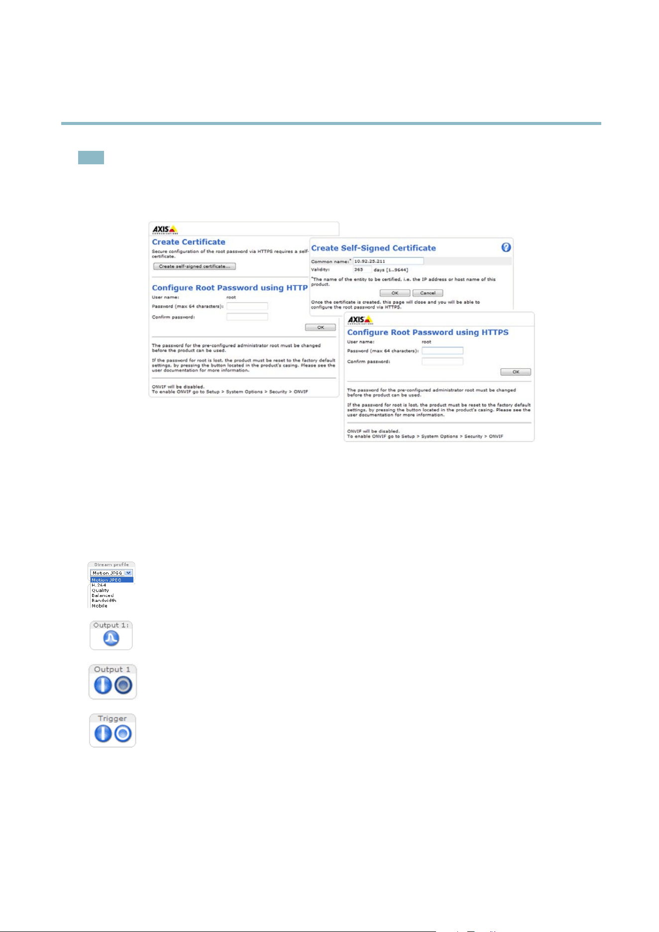
Set the Root Password
To gain access to the Axis product, you must set the password for the d efault administrator user root. This is done in the Configure
Root Password dialog, which appears w hen the product is accessed for the first t ime.
To prevent network eavesdropping, the root password can be set via an encrypted HTTPS connection, which requires an HTTPS
certificate. HTTPS (Hypertext Transfer Protocol over SSL) is a protocol used to encrypt traffic between web browsers and servers. The
HTTPS certificate ensures encrypted exchange of information.
To set the password via a standard HTTP connection, enter it directly in the first dialog.
To set the password via an encrypted HTTPS connection, follow these steps:
1. Click Create self-signed certificate.
2. Provide the requested information and click OK.Thecertificate is created and the passwo rd can now be set securely. All
traffic to and from the product is encrypted from this point on.
3. Enter a passw ord and then re-enter to confirm the spelling. Click OK. The password has now been configured.
8
AXIS Q7424–R
Accessing the Product
Note
• The default administrator user name root is permanent and cannot be deleted.
• If the password for root is lost, the product must be reset to the factory default settings. See
Reset to Factory Default
Settings, on page 47
.
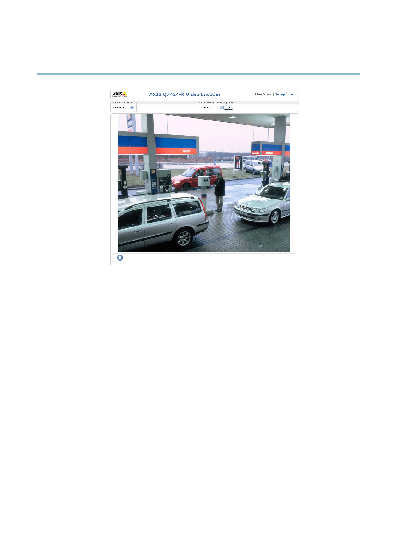
TheLiveViewPage
The controls and layout of the Live View page may have been customized to meet specific installation requirements a nd user
preferences. Consequently, some of the examples and functions featured here m ay differ from those displayed in your own Live View
page. The following provides an overview of each available control.
Controls on the Live View Page
The Stream Profi le drop-down list allows yo u to select a customized or pre-programmed stream profile. Stream
profiles are configured under Video & Audio > Stream Profiles.See
Stream Profiles, on page 17
.
Click Pulse to activate the output for a defined period of time, such as sw itching on an exte rnal light for 20 seconds.
Click the Active/Inactive buttons to manu
ally start and stop a connected device — e.g. s witch an external light
on and off.
The Manual Trigger button can trigger an event directly from the Live View page. The button is configured under
Live View Config > Action Buttons.
9
AXIS Q7424–R
Accessing the Product
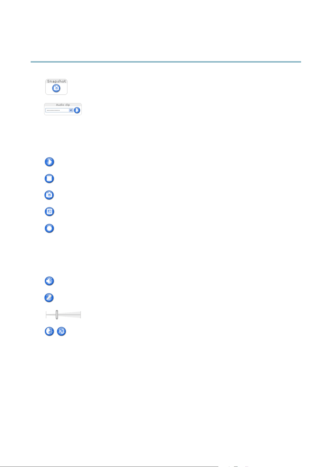
Click Snapshot to save a snapshot of the video image. Right-click the video image to save it in JPEG form at on your
computer. This button is primarily intended for use when the A XI S M e d ia C o ntrol vie wer toolbar is not availab le.
Enable this button from Live View Config > Action Buttons.
The Audio clip drop-down list allows you to play an audio clip from the Live View page. Select the audio
clip and click the Play button.
AXIS Media Control viewer toolbar
The AXIS Media Control viewer toolb ar is available in Internet Explore r only. See
AXIS Media Control (AMC), on page 12
for more
information. The toolbar displays the following buttons:
The Play button connects to the Axis product and starts playing a media stream.
The Stop button stops the media stream.
The Snapshot button takes a s napshot of the video image. The locationwheretheimageissavedcanbespecifi ed
in the AMC Control Panel.
Click the View Full Screen button and the video ima ge will fi ll the entire screen. Press ESC (Escape) on the computer
keyboard to cancel full screen view.
The Record button is used to record the curr ent vide o strea m . The location where the recording is saved can be specified
in the AMC Control Panel.
AMC Audio Controls
AMC audio buttons control the speakers and micro phone connected to the client computer. The buttons are only visible when
audio is enabled.
Speaker button — Click to turn the speakers on or off.
Microphone button – C lick to mute or unmute the microphone. In Simplex - Network Camera speaker only mode,
click this button to stop sending audio to the product.
Use the slider to control the volume of the speakers and the microphone.
Half-duplex mode
The Talk/Listen button is use d to switch betw
een sending and receiving audio. The button can be configured
from the Audio tab in the AMC Co ntrol panel:
• Push-To-Talk mode: Click and hold the button to talk/send. Release the button to listen.
• Toggle mode: Click once to switch betwee
n talking and listening.
Simplex – Network Camera speaker only mode
To send audio, the Talk and Micro phone buttons must both be enabled. Click either button to stop audio
transmission.
PTZ Controls
TheLiveViewpagealsod
isplays Pan/Tilt/Zoom (PTZ) controls. The administrator can e nabl e/disable controls for specified users under
System Options > Security > Users.
With the PTZ Control Queue enabled the time each user is in control of the PTZ settings is limited. Click the buttons to request or
release control of the PTZ controls. The PTZ Control Queue is set up under PTZ > Control Q ueue.
10
AXIS Q7424–R
Accessing the Product
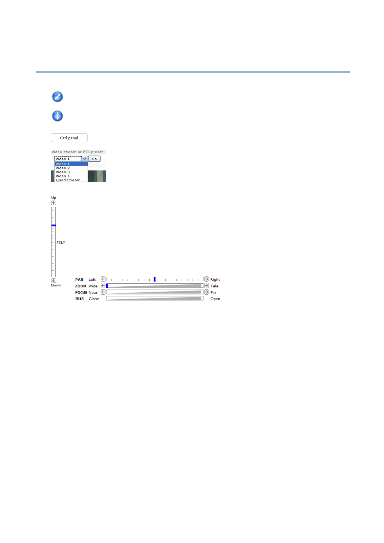
Click the Emulate joystick mode button and click in the image to move the camera view in the direction of the
mouse pointer.
Click the Center mode button and click in the image to center the camera view on that positio n. The cente r mode
button could also be used to zoom in on a specific are a. Click in the i m age a n d drag to draw a rectangle surroundi n g
theareatobemagnified. To zoom out, rotate the mouse wheel.
Click the Ctrl panel button to open the PTZ control panel w hich pro vides additional PTZ controls.
User-defined buttons can also appear in the Control panel. See
Controls, on page 27
.
Select the video channel or a PTZ preset position to steer the camera view to the saved position. See
Preset Positions, on pag e 25
.
Pan and Tilt bars – Use the arrows to pan and tilt the camera view, or click on a position on the bar to steer the
camera view to that position.
Zoom bar – Use the arrows to zoom in and out, or click on a position on the bar to zoom to that position.
Focus bar – Use the arro ws to focus the camera, or click on a position on the bar to set the focus position. Using the
focus bar will disable the product’s autofocus. To re-enable, use the PTZ control panel which is opened by clicking
the Ctrl panel button (see above).
Iris ba r – Click on a position on the iris bar to change the degree to which the iris is opened . This will disable the
product’s auto iris. To re-enable, use the PTZ control panel wh ich is opened by clicking the Ctrl panel button (see above).
The PTZ controls can be disabled under PTZ > Advanced > Controls,see
Controls, on page 27
.
11

AXIS Q7424–R
Media Streams
Media Streams
The Axis product provides several audio and video stream formats. Your requirements and the properties of your network will
determine the type you use.
The Live View page in the product provides access to H.264 and Motion JPEG video streams, audio streamsandtothelistofavailable
stream profiles. Other applications and clients can access video and audio streams directly, without going via the Live View page.
How to Stream H.264
The video compression standard H.264 makes good use o f bandw idth, and can p rovide high quality vid eo streams a t less than 1 M bit/s.
Deciding which combination of protocols and methods to use depends on your viewing requirements, and on the properties of
your network. The available options in AXIS Media Control are:
Unicast RTP
This unicast method (RTP over UDP) is used
for live uni cast video, especially w hen it is
important to always have an up-to-date video
stream, even if some images are dropped.
RTP over RTSP
This unicast method (RTP tunneled over RTSP)
is useful as it is relatively simple to configure
firewallstoallowRTSPtraffic.
RTP over RTSP over HTTP
This unicast method can be used to traverse
firewalls. Firewalls are c ommonly configured to
allow the HTTP protocol, thus allowing RTP to
be tunneled.
Unicasting is used for video-on-demand
transmission so that there is no video traffic
on the network until a client connects and
requests the stream.
Note that there are a maximum of 20
simultaneous unicast connections.
Multicast RTP
This method (RTP over UDP) should be used for liv e m ulticast video. The video stream is always
up-to-date, even if some im ages are dropped.
Multicasting provides the m ost efficient usage of bandwidth when there are large numbers of
clients viewing simultaneously. A multicast cannot however, pass a network router unless the
router is configured to allow this. It is not possible to mul ticast over the Internet, for example.
Note a lso that all multicast viewers c ount as one unicast viewer in the maximum total of 20
simultaneous connections.
AXIS Media Control negotiates with the Axis product to determine the transport protocol to use. The order of priority, listed in the
AMC Control Panel, can be c hang ed and the options disabled, to suit specific requirements.
Note
H.264 is licensed technology. The Axis product includes one H.264 viewing client licens e. Installing additional unlice nse d
copies of the client is prohibited. To
purchase additional licen se s, contact your Axis re se ller.
MJPEG
This format uses st anda rd JPEG still ima ges f o r the video stream. These images are then displayedandupdatedataratesufficient
to create a stream that shows constantly updated motion.
The Motion JPEG stream uses considerable amounts of bandwidth, but provides excellent image qualityandaccesstoeveryimage
contained in the stream. The recommended method of accessing Motion JPEG live vid eo from the Axis product is to use the AXIS
Media C ontrol in Internet Explorer in Windows.
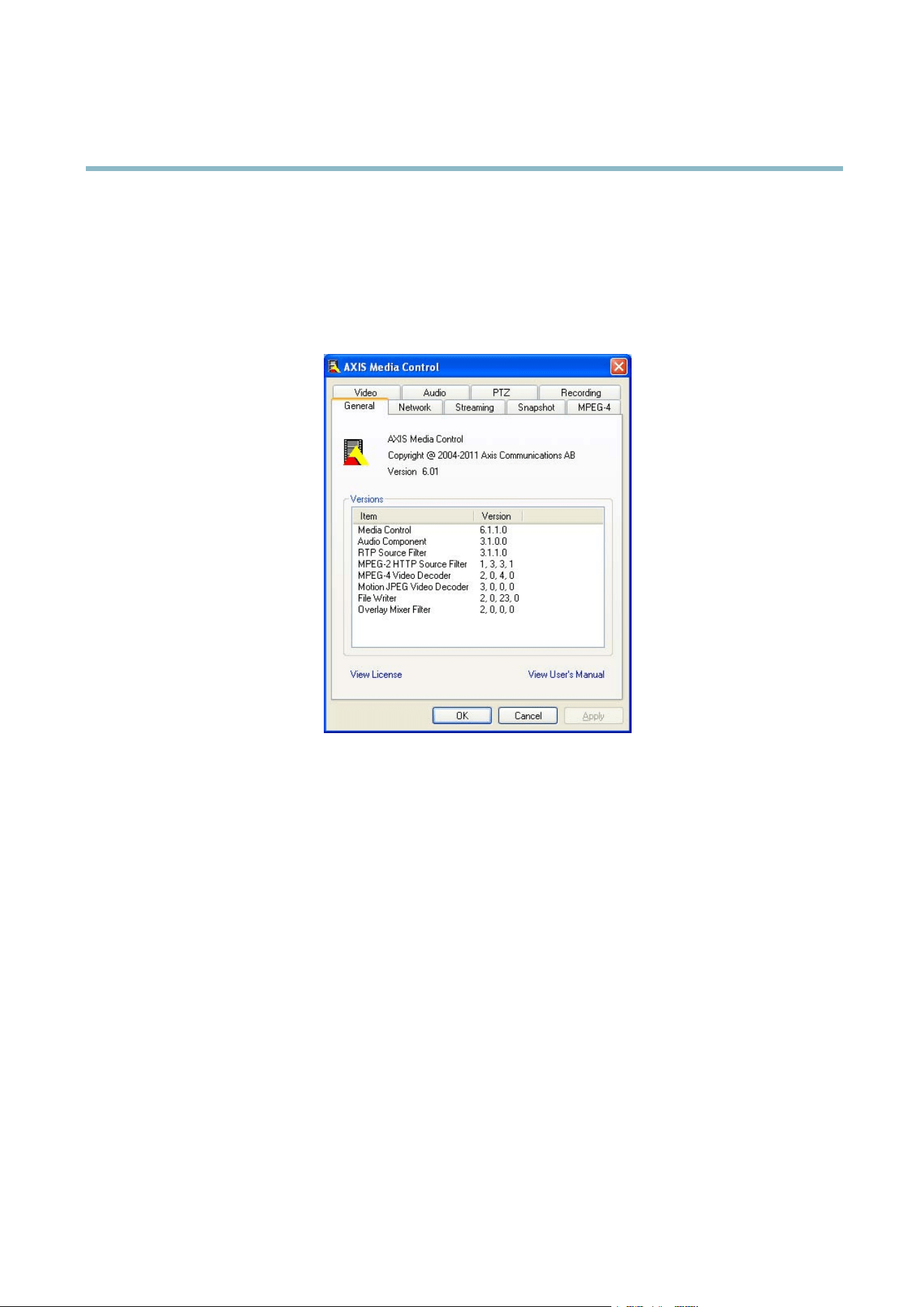
AXIS Media Control (AMC)
AXIS Med ia Control (AMC) in Internet E xp lorer in Windows is the recommended method of accessing live video from the Axis product.
12
AXIS Q7424–R
Media Streams
TheAMCControlPanelcanbeusedtoconfigure various video an d audio settings. Please see the AXIS Media Control User’s
Manual for more information.
The AMC Control Panel is autom a tically instal led on fi rst use, after which it can be configured. Open the A MC Control Panel from:
• Windows Control Panel (from the Start menu)
• Alternatively, right-click the video im age in Interne t Explorer an d click Settings.
Alternative Methods of Accessing t he Video Stream
You can also access vide o and image s from the Axis product in the following ways:
• Motion JPEG server push (if s upported by the client, Firefox, for example). This option maintains an open HTTP connection
to the brow s er and send s data as and when required, for as long as required.
• Still JPEG images in a browser.Enterthepathhttp://<ip>/axis-cgi/jpg/image.cgi
• Windows M edia Player. This requires AXIS Media Control and the H.264 decoder to be installed. The following paths
can be used:
- Unicast via RTP : axrtpu://<ip>/axis-media/media.amp
- Unicast via RTSP: axrtsp://<ip>/axis-media/media.amp
- Unicast via RTSP, tunneled via HTTP: axrtsphttp://<ip>/axis-media/media.amp
-Multicast:axrtpm://<ip>/axis-media/media.amp
• QuickTime
TM
. The follo wing paths can be used:
- rtsp://<ip>/axis-media/media.amp
- rtsp://<ip>/axis-media/media.3gp
13

AXIS Q7424–R
Media Streams
Note
• <ip>= IP addess
• The Axis product supports QuickTime 6.5.1 and later.
• Q uickTime adds latency to the video stream.
• It may be possible to use other players to view the H.264 stream using the paths above, although Axis does not guarantee
this.
Accessing Audio Streams
The Live Vie w pag e provides access to audio through AXIS Media Control; in addition audio can be accessed in the following ways:
• VAPIX® Application Program m ing Interface (API) For more information, visit www.axis.com/developer
• Windows Media Player supports simplex audio. The following paths can be used:
- Unicast via RTP : axrtpu://<ip>/axis-media/media.amp
- Unicast via RTSP: axrtsp://<ip>/axis-media/media.amp
- Unicast via RTSP, tunneled via HTTP: axrtsphttp://<ip>/axis-media/media.amp
-Multicast:axrtpm://<ip>/axis-media/media.amp
• QuickTime
TM
supports G.711 and AAC audio encod ing. The following paths can be used:
- rtsp://<ip>/axis-media/media.amp
- rtsp://<ip>/axis-media/media.3gp
•TheJava applet supports simplex audio with G.711 encoding.
14

AXIS Q7424–R
Setting Up the Product
Setting Up the Product
The Axis product can be configured by users with a dm inistrator or ope rator rights. Click Setup in the top right-hand corner of
theLiveViewpage.
• Administrators have unrestricted access to all settings.
• Operators have access to all settings except System Options
See also the online help .
Basic Setup
Basic Setup provides shortcuts to the settings thatshouldbemadebeforeusingtheAxisproduct:
1. Users. See
page 37
.
2. TCP/IP. See
page 39
.
3. Date & Time. See
page 38
.
4. Video Stream. See
page 16
.
5. Audio Settings. See
page 19
.
The Basic Setup menu can be disabled from System Options > Security > Users.
15
AXIS Q7424–R
Video and Audio
Video and Audio
The video and audio settings can be used to optimize video an d audio quality. You ca n configure the following:
• Video stream se ttin g s. See
page 16
.
•Streamprofiles. See
page 17
.
• Camera settings. See
page 17
.
• Overlay image. See
page 18
.
•Privacymask.See
page 18
.
• Audio settings. See
page 19
.
• Audio clips. See
page 21
.
Video Stream
You can defi ne the following video strea m settings from Video & Audio > Video Stream:
•Image.See
page 16
.
• H.264. See
page 17
.
•MJPEG.See
page 17
.
Note
Video stream can be configured for each channel including quad stream.
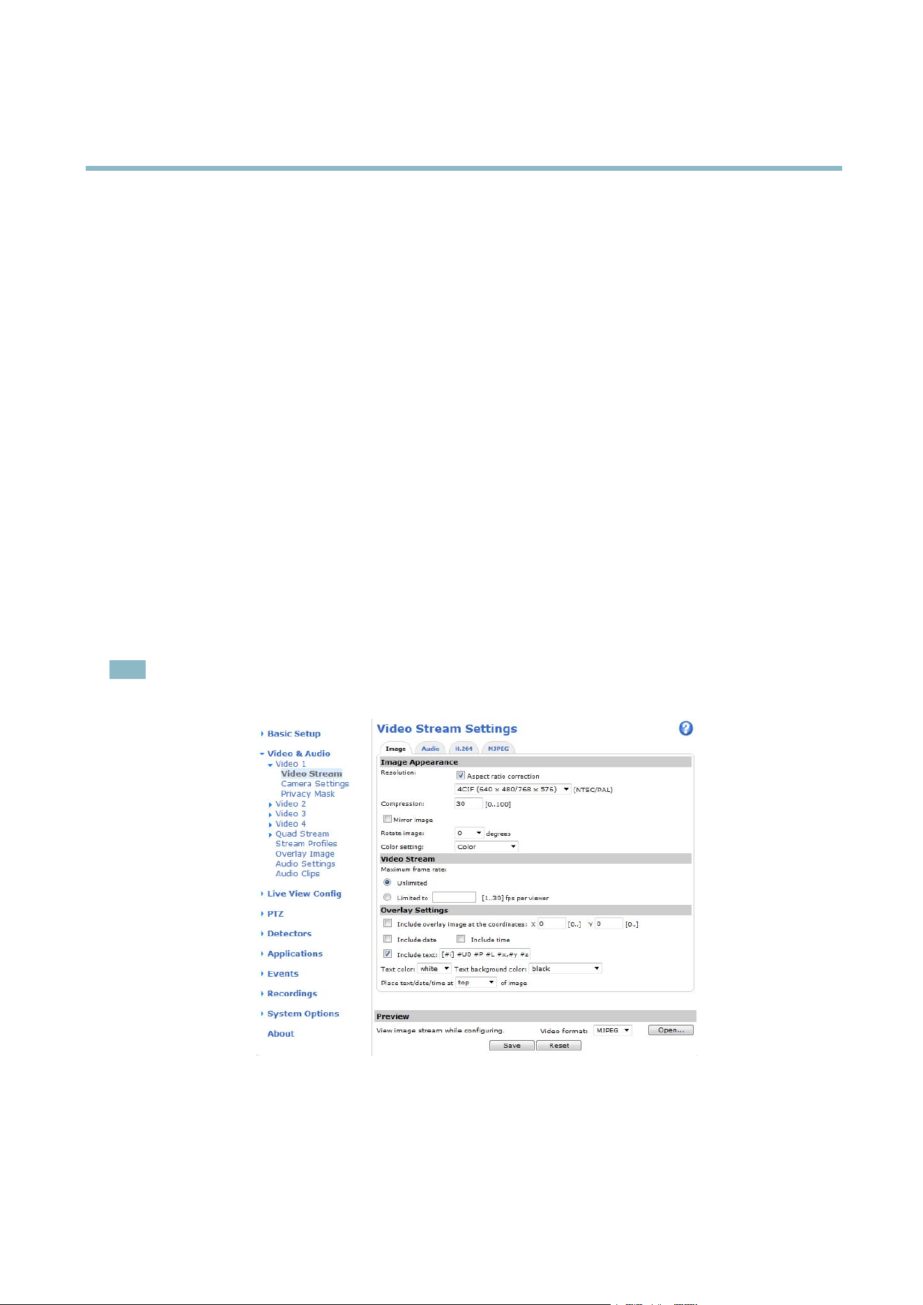
Image
You can m odify the image resolution and compression, and rotate the image from the Image tab (Video & Audio > Video Stream).
The im ag e can also be mirrore d fro m the Ima ge tab.
16

AXIS Q7424–R
Video and Audio
Setting the compression level affects the image quality and bandwidth; the lower the compressio n, the higher the image quality
with higher bandw idth requirements.
To avoid bandwidth problems on the network, you can limit the frame rate allowed to each viewer. The maxim um fra m e rate ca n be
set to Unlimited, or you can limit the frame rate to a value.
An image or text can be superimposed over the image as overlay. See
Overlay, on pag e 18
.
Save your setting s before they can take effect.
H.264
H.264, also known as M PEG-4 Part 10/AVC, is a video compression standard that provides high quality video streams at low bit r ates.
An H.264 video stream consists of different types of frames such as I-frames and P-frames. An I-frame is a complete image whereas
P-frames only contain the differences from previous frames.
The GOV length is the number of frames between two consecutive I-frames. Increasing the GOV length may save considerably on
bandwidth requirements in some cases, but may also have an adverse affect on image q uality.
ThebitratecanbesetasVariable Bit Rate (VBR) or Constant Bit Rate (C BR ). VB R adjusts the bit rate according to the image
complexity, using up more bandwidth for increased activity in the image, and less for lower image activity. CBR allows you to set a
fixed Target bit rate that consumes a predictable amount of band width. As the bit rate would usually need to increas e for increased
image activity, but in this case cannot, frame rate and image qualityareaffectednegatively. Topartly compensate for this, it is
possible to prioritize either fra m e rate or im age quality. Not setting a priority me ans that frame r ate and image quality are equally
affected. You mu st sa ve you r settin g s bef ore they can take effec t .
The current bit rate can be set to a ppear as text overlay. To do this, select the Include text check box option under Overlay
Settings and enter the modifier#b in the field.
MJPEG
Sometimes the image size is large due to low light or complex scenery. Adjusting the maxi
mum frame size helps to control the
bandwidth and storage used by the Motion JPEG video stream i n these situations. Setting the frame size to the Default setting
provides consistently good image quality at the expense of increased bandwidth and storage usage in low light. Limiting the frame
size optimizes bandwidth and storage usage, but may give poor image quality. To
prevent increased bandwidth and storage usage,
the ma ximum fram e size should be set to an optimal value.
Quad stream
A Quad view displays images from all four channe ls on a single scre e n; where the ima ge s from each came ra take up a quarter of
the display area. It is possible to define settings for the video stream in quad view.
Stream Profiles
There are four pre-programmed stream profile s available for quick set up. The settings for these can be adjusted. New customized
profiles can also be created. Each profile has a descriptive name, indicating its purpose.
•Thestreamprofiles can be accessed from the Stream profile dro p-dow n list in the Live View page.
• To add, copy, modify, and remove stream profiles go to Video & Audio > Stream Profiles.
• To select the def ault stream profile go to Live View Config > Stream Profile and choose the profile from the drop-down list.
For more information see the online help
on this page.
Camera Settings
The Video & Audio > Camera Settings page provides access to advanced image settings for the Axis product.
17

AXIS Q7424–R
Video and Audio
Image Appearance
Increasing the Color level increases the color saturation. The value 100 gives maximum color saturation. The value 0 gives a
black and white image.
The image Brightness can be adjusted in the range 0–100, where a higher value produces a brighter image.
The Contrast change s the re lati ve difference betwee n lig ht and dark. It can be adjusted using the slidebar.
Video input
• Enter a descriptive name for your video source in the Video source name field.
• The values in the Offset Adjustments fields affect the horizontal and vertical synchronization for the image. T his can be used
to eliminate any bla ck border surrounding the imag e. High values, both negative and positive can put the image out of sync.
• De-interlacing - is used to improve video stream image quality f rom analog devices. Select any of the follow ing options
from the De-interlacing drop-down list. Select None if de-interlacing is not necessary; Blending for improve d image quality
that is not as processor intensive; Adaptive Interpolation performs de-interla c ing of the video stream by applying di ffe rent
filters on the image. This may give a better result than M otion Adaptive Interpolation in r are cases; Motion Adaptive
Interpolation performs de-interlacing of the vide o stream by applying different filters depending on the m otion in different
parts of the imag e. This will in most cases re sult in the best ima g e quality.
• Antialiasing will minimize distortion known as aliasing, which happens when a high-resolution image is repres ented at
alowerresolution.
• For each video input 75 Ohm video termination can be enabled/d isabled via the product's web page at V ideo & Audio >
Video Input > Video termination. These terminatio ns are enabled on factory default. In cases where the p roduct is to be
connected in parallel with other equipment, for optimum video quality, it is recommended that terminatio n be enabled for
only the last device in the video sig nal chain.
Image Settings
Noise reduction - Set to On to enable nois e reduction. Noise reduction may increase
the amount of motion blur.
Privacy Mask
A privacy mask is an ar ea of solid color that pr
ohibits users from viewi ng parts of the monitored area. Privacy masks cannot be
bypassed via the VAPIX® Application P ro gramming Inte rfa ce (API).
The Privacy M ask List (Video & Audio > Privacy Mask) shows all the masks that are currently configured in the Axis pro duct and
indicates if they are enabled.
You can add a new mask, re-size the mask with the mouse, choose a color for the mask, and give the mask a name.
For m ore information, see the online help
Note
Privacy mask is not available for the quad stre am. However, privacy masks configured on each channel will be displayed
in the qua d.
Overlay
Overlays are used to provide extra information, for example for forensic video analysis or duri n g product installation and
configuration. Overlays are superimposed over the video stream.
An overlay text can display the current da te a nd time, or a text string. W hen using a text string, modifiers can be used to display
information s uch a s the current bit rate or the current frame r ate. For information about available modifiers, see
File Naming &
Date/Time Formats
in the online help .
18

AXIS Q7424–R
Video and Audio
To enable overlays:
1. Go to Video & Audio > Video Stream and select the Ima ge tab.
2. To include an overlay image, select Include overlay image at the coordinates. The overlay image must first be uploaded to
the A xis product, see
Overlay Image
.
3. To include date and time, select Include date and Include time.
4. To include a text string, select Include text and enter the text in the field. Modifiers can be used, see
File Naming &
Date/Time Formats
in the o nline he lp .
5. Select the text color, the text background color and the position of the overlay.
6. Click Save.
Tomodifythedateandtimeformat,gotoSystem Options > Date & Time.See
Date & Time, on page 38
.
Note
Overlay is not poss ible f o r quad stream.
Overlay Image
An overlay image is a static image superimposed over the video stream. The image, for example company logo, is used to provide
extra information or to mask a part of the image.
To use an overlay image, the image must first be uploaded to the Axis product:
1. Go to Video & Audio > Overlay Image.
2. Click Brow se andbrowsetothefile.
3. Click Upload.
4. Select the image to use from the Use overlay image list.
5. Click Save.
To display the overlay image:
1. Go to Video & Audio > Video Stream and select the Image tab.
2. Under Overlay Settings,selectInclude overlay image at the coordinates and enter the X and Y coordinates.
3. Click Save.
For information about supported image formats, see the online help
.
Au
dio Settings
The audio functionality for each video stream is enabled under Video & Audio > Video Stream > Audio.
Select the desired audio channel from the drop-down list.
Audio Channels
Select the type o f audio transm is sion fr om the Audio mode: drop-down list (Video & Audio> Audio Settings). The different types are:
Full duplex - Simultaneous two-way audio allowing you to transmit and receive audio (talk and listen) at the same time. There is no
echo cancellation; if feedback loops appear, try moving the microphone or the speaker.
19

AXIS Q7424–R
Video and Audio
Half-duplex - Audio can b e transmitted in both directions between th e Axis product and the client computer, but only in one
direction at a time. You must actively receive sound using the Talk/Listen button v is ible in the Live View page (see
AXIS Media
Control viewer toolbar
). In Push-To-Talk mode, click and ho ld the button to speak and release it when done. In Toggle mod e, click
once to switch between speaking and listening. The Talk/Listen mode is configured from the Audio tab in the AMC control panel
(see A XIS Media C ontro l on
page 12
).
Simplex - Network Camera speaker only - Audio is transmitted from the client to the Axis product and played by the speaker
connected to the product. To send audio, the Talk and Microphone buttons in the AMC toolbar m ust both be enabled. Click either
button to stop audio tran smissio n .
Simplex - Network Camera microphone only - A udio captured by the microphone connected to the Axis product is tra nsmitted from
theproducttooneormoreclients.
For more information ab ou t these settings, please see the online help
.
Audio Input
Source - Select Microphone for an external microphone or Line for a Line in device, e.g. a n audio mixer for multiple microphones or
a microphone with a built-in am plifier.
Microphone power - The E nable microphone po wer o ption provides DC power f or an external microphone. Microphone power
should only be used with microphones that have no battery. This setting should not be enabled when using a dynamic or battery
powered microphone. Microphone pow er will not harm the microphone; if you are uncertain, try switching it off and on. To use a
professional microphone requiring 48V phantom power, you need an external power supply and a balanced-unbalanced converter
(audio transform e r) in between.
Input gain - Control the volume (dB Full Scale) of the aud io input. If the sound is too low, choose a higher dB, to amplify the
sound. If the sound is too high, choose a lower dB. The Level bar gives a visua l representa tion of the audio signal level in dB
relative to the full-scale input level.
• Green — the signal is at a good level.
• Yellow — the signal is becoming d istorted.
• Red — the signal is distorted.
Encoding - Select digital audio encoding format.
• AAC requires a license for both encoding and decoding. AAC is the least complicated and most widely used codec.
If achieving the best possible audio quality is a priority, AAC is the r ecommended codec to use. A n AAC license
is included in the Axis pr oduct.
• G711
• G726
Sample rate - The number of tim es per second the sound is sampled. A higher sample rate will provide b ette r a udio quality, but
also requires a greate r b andwidth.
Bit rate - Set the required bit rate depending on the selected encoding. A higher bit rate will give better audio quality. A lower bit
rate m ay hav
e latency or delay, but will require less bandwidth.
For more
information about these settings, please see the online help
.
Audio Output
Configure the audio output settings under Video & Audio > Audio Settings.
20

AXIS Q7424–R
Video and Audio
Output gain - Control the volume (dB Full Scale) of the line audio output. If the sound is too low, choose a higher dB. If the
sound is too high, choose a lower dB.
Audio Clips
An audio clip is a sound file that can be played either whe n a n event occurs or manually from the Live View page. Audio clips can
be uploaded to the product or recorded by a microphone connected to the prod uct.
You can add, play, download, modify and remove audio clips from Video & Audio > A udio Clips. For more information see the
online help
.
Note
Audio clips cannot be used if the product’s audio functionality is enabled. The audio functionality is enabled on the Audio
tab under Video & Audio > Video Stream.
21
AXIS Q7424–R
Live View Config
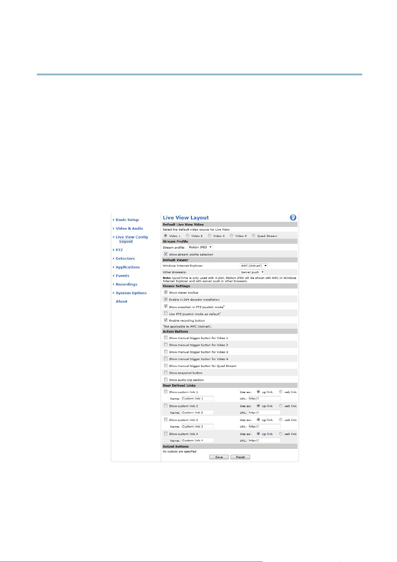
Live View Config
You can customize the Live View page and alter it to suit your requirements. It is possible to define the following features of
theLiveViewpage.
•StreamProfile. S ee
page 17
.
• Default Viewer for Browser. See
page 23
.
• Viewer Settings. See
page 23
.
• Action Buttons. These are the buttons described in
Controls on the Live View Page, on page 9
.
•UserDefined Links. See
page 23
.
• Output B uttons. See
page 23
.
Default live view video
Select the d efa u lt video source to be displa yed in the Live View page from Setup > Live View Config This could be one of the 4
video streams or Q uad stream. See
Quad stre am, on page 17
.
22

AXIS Q7424–R
Live View Config
Default Viewer for Browsers
From Live View Config > Default Viewer se le ct the default method for viewing video images in your browser. The product attem pts
to show the video images in the selected video f orm at and v ie we r. If this is not possi ble, the product overrides the settings and
selects the best available comb ination.
Browser Viewer Description
AMC
Recommended viewer in Internet Explorer (H.264/Motion JPEG)
QuickTime
H.264
Java applet
A slower imaging alternative to AMC (Motion JPE G ) . R equires one of the
following installed on the client:
• JVM (J2SE) 1.4.2 or higher
• JRE (J2SE) 5.0 or higher
Windows Internet Explorer
Still image Displays still images only. Click the Refresh button in your browser to view a
new image
Server Push
Recommended viewer for other browsers (M otion JPEG).
QuickTime
H.264
Java applet
A slower imaging alternative to Serve r Push (Motion JPEG only).
Other browsers
Still image Displays still images only. Click the Refresh button in your browser to view a
new image
For more inform a tion, please see the online help .
Viewer Settings
Options for the viewer are configured under Live View Config > Viewer Settings.
•TheShow viewer toolbar option will display the A X IS Media Control (AMC) or the QuickTime viewer toolbar under the
video image in your browser.
• H.264 decoder installation. The administrator can disable installation of the H.264 decoder included w ith AXIS Media
Control. This is used to prevent installation of unlicensed copies. Further decoder licenses can be purcha se d from your
Axis res elle r.
•SelectShow crosshair in PTZ joystick mode to enable a cros s that will ind icate the cente r of the image in PTZ joystick mode.
•SelectUse PTZ joystick mode as default to enable joystick mode. The mode can be changed temporarily from the PTZ
control panel.
• You can enable recording from the Live View page. The recordings are saved to the location specified in the AMC Control
Panel. See
AXIS Media C ontrol (AMC), on page 12
.
User Defined Links
To display user-defined links in the Live View page, s elect the Show custom link option, give the link a name and then enter the URL
to link to. W hen defining a web link do not remove the 'http://' from the URL address. Custom links can be used to run scripts or
activate external devices connected to the product, or they can link to a web p age . Custom links defined as cgi links will run the
script in the background, in a hidden frame. D efining the link as a web link will open the link in a new window.
Output Buttons
An output on the Axis product can be controlled directly from the Live View page, by enabling the d isplay of o utput buttons. To
display the output buttons in the Live View page, select the type of control to use for the port from the drop-dow n list under
Live View Config > Output Buttons:
23

AXIS Q7424–R
Live View Config
• Pulse activates the output for a definedperiodoftime. Thepulsetimecanbe set as short as 1/100 second, and as
long as 60 seconds
• Active/Inactive displays two buttons (on/off). The output ports must first be configured under System Options> Ports &
Devices > I/O Ports.See
I/O Ports, on page 44
.
24

AXIS Q7424–R
PTZ (Pan Tilt Zoom)
PTZ (Pan Tilt Zoom)
Installing a PTZ driver
This Axis product supports several PTZ devices. Please see www.axis.com for a complete list of supported devices, and to obtain the
correct driver. To install a PTZ de vice you need to install the PTZ driver.
To install the PTZ driver go to PTZ> Driver Selection. Browse to find the driver (e.g. driver.ptz) and Upload.Ifthedriverwas
successfully uploaded, it appears in the Select driver to use drop-down list. From this drop-down list, select the driver to insta ll
or remove, and click Save .
Select Activate PTZ to enable PTZ. The address of the connected device appears against Device ID. Choose the Device type from the
drop-down list. To find which device type to use, consult the documentation supplied by the PTZ driver.
To complete the installation go to System Options > Ports & Devices > COM Port (see
COM Port
) and verify the settings.
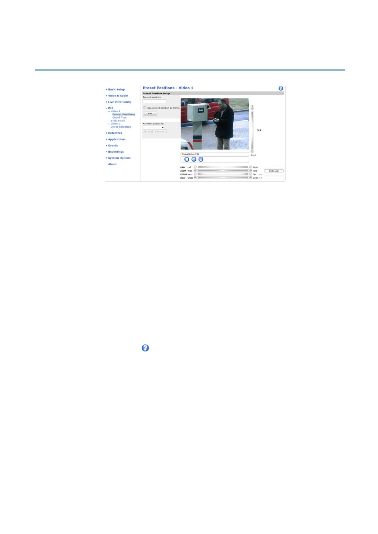
Preset Positions
A preset position is a predefined view that can be used to quickly s teer the camera to a specific location. Preset positions can
be accessed in several w ays:
• By selecting the preset from the Preset positions drop-down list in the Live View Page.
• When setting up action rules. See
page 31
.
• When setting up Guard Tour. See
page 26
.
To add a preset position:
1. Go to PTZ > Preset Positions.
2. Use the pan, tilt and zoom controls to steer the camera view to the desired position.
3. Enter a descriptive name in the Current position field.
4. If required, select Use current position as Home.
5. Click Add.Thecamera’sposition,irisandfocussettingsaresavedasapresetposition.
The Home po sition is readily accessible by clicking the Hom e button on the Live View page and in the Preset Positions setup window.
To set a cus tomize d home position, select Use current position as Home w h en adding a preset position. The user-defined home
position will have (H) added, for example, Entrance (H). The default Home position, called “Hom e”, will still be available .
The product can be configured to return to the Home position when the PTZ functionality has been inactive for a spec ifi ed length
of
time. E nter the length of time in the Return to home when inactive field and click Save.Setthetimetozerotopreventthe
product fr om automa tically returning to the Home position.
To include the preset position name in the overlay text, go to Video & Audio,selectInclude overlay text and enter the m o difi er #P in
the field. For more information about modifiers, see
File Nam i n g & Date/Time F ormats
in the online help .
25
AXIS Q7424–R
PTZ (Pan Tilt Zoom)
Guard Tour
A guard tour displays the video st re am from different preset po sitions, one-by-one, in a predetermined order or at random and for
configurable time periods. The enabled gua rd tour will keep running after the user has logged off or closed the browser.
Toaddaguardtour:
1. Go to PTZ>GuardTourand click Add.
2. Enter a descriptive n ame.
3. Specify the pause length between runs.
4. Select an available prese t position and click Apply.
5. Specify the Move speed.
6. Specify the View Time in seconds or minutes.
7. Specify the View order or select the Random view order check box option.
8. Click Save.
To modify or rem ove guard tours, go to PTZ>GuardTour, select the guard tour in the Guard Tour List and click Modify/Remove.
For m ore information see the online h
elp
.
Advanced
Device Settings
TheDeviceSe
ttings window displays driver specific settings. The appearance of this window can vary depending on the driver
installed. Options that can be configured include:
• Driver Specific Settings fro m Vide o Source
• Mechanical Limits for Moving Video Source
• Light Control Video Source
• Extended Driver Specific Settings for Video Source
For download and installation information about PTZ drivers for your Axis product please visit www.axis.com/techsup/
26

AXIS Q7424–R
PTZ (Pan Tilt Zoom)
Controls
Panel Shortcut Command Buttons can be co nfig u red to provide direct access to comm ands issued via the VAPIX® Application
Programming Interface. The buttons will be displayed in the PTZ control panel, which is available in the Live View page through
the Ctrl panel button, see
page 10
.
Deselect the options under Enable/Disa ble controls to disable the pan, tilt, zoom, focus and iris controls.
Note
Disabling PTZ controls will not affect preset positions. For exa m ple , if the tilt control is disabled, the product ca n still move to
preset positions that require a tilt movement.
OSD Menu
If the PTZ unit supports an internal configuration m enu, this can be accessed using the On-Screen Display (OSD). Configure the
analog camera by op ening and navigating through its internal menu in this displa y.
27

AXIS Q7424–R
Applications
Applications
Third p arty ap plications can be uploaded to and installe d on the Axis product. For information about available applications,
downloads, trials and licenses, go to www.axis.com/applica tions
To upload an applica tion, go to Applications > Overview, click Browse to locate the file and then click Upload Package. Click on the
uploaded application’s name to open the menu options Settings, License and About.Forconfigura ti on ins tructions, please refer to
the documentation provided with the application.
Most applications need a license to run. To install the license, select the License menu option. If the product is connected
to the Internet, Automatic Installation appears in the web page. If the prod uct is not connected to the Internet, go to
www.axis.com/ applications to acquire a License ke y. You will ne ed a license code and the product’s serial number (found on the label
and under System Options > Support > System Overview) to receive a license key.
Installed Applications lists installed applications with information a bout the ver sion a nd the ven dor, the status of the a pplica tion
(running or not r unning), and information about the license.
Use the Start and Stop buttons to start and stop the application.
To generate a log file for the application, select the application and click Log.
Note
It is recommended to run one application at a time. A void running app licatio ns when motion detection is active.
Applications are only supported on channel 1.
28

AXIS Q7424–R
Detectors
Detectors
Camera Tampering
Camera Ta m per ing can genera te an alarm whenever the camera is repositioned, or when the lens is covered, sprayed or severely
defocused. To send an alarm, for example an email, an action rule must be set u p.
To configure tampering:
1. Go to Detectors > Camera Tampering.
2. Set the Minimum duration, that is, the tim e that must elapse before an alarm is genera ted. This can help pre vent false
alarms for known conditions that affect the image.
3. Select Alarm for dark images if an alarm should b e gen e rated if lights are dimmed or turned off, or if the lens is sprayed,
covered, or rendered severely out of focus.
4. Click Save.
To configure the pro duct to send an alarm when tampering occurs:
1. Go to Events > Action Rules.
2. Click Add to set up a new action r ule.
3. Enter a Name for the action r u le.
4. Under Condition,selectDetectors from the Trigger list.
5. Select Tamp erin g from the list of detectors.
6. Select the video channel.
7. Optionally, sele ct a schedule and set additional conditions
.
8. Select the action. To send an e m ail, select Send Notifi
cation and select a Recipient from the list of defined recipients.
Note
The While the rule is active op tion under Duration cannot be used with camera tampering, since camera tampering does not
have a duration and once it has been triggered it will not automatically re turn to its untrigge re d state .
For more information on actions rules, see
Events, on page 31
.
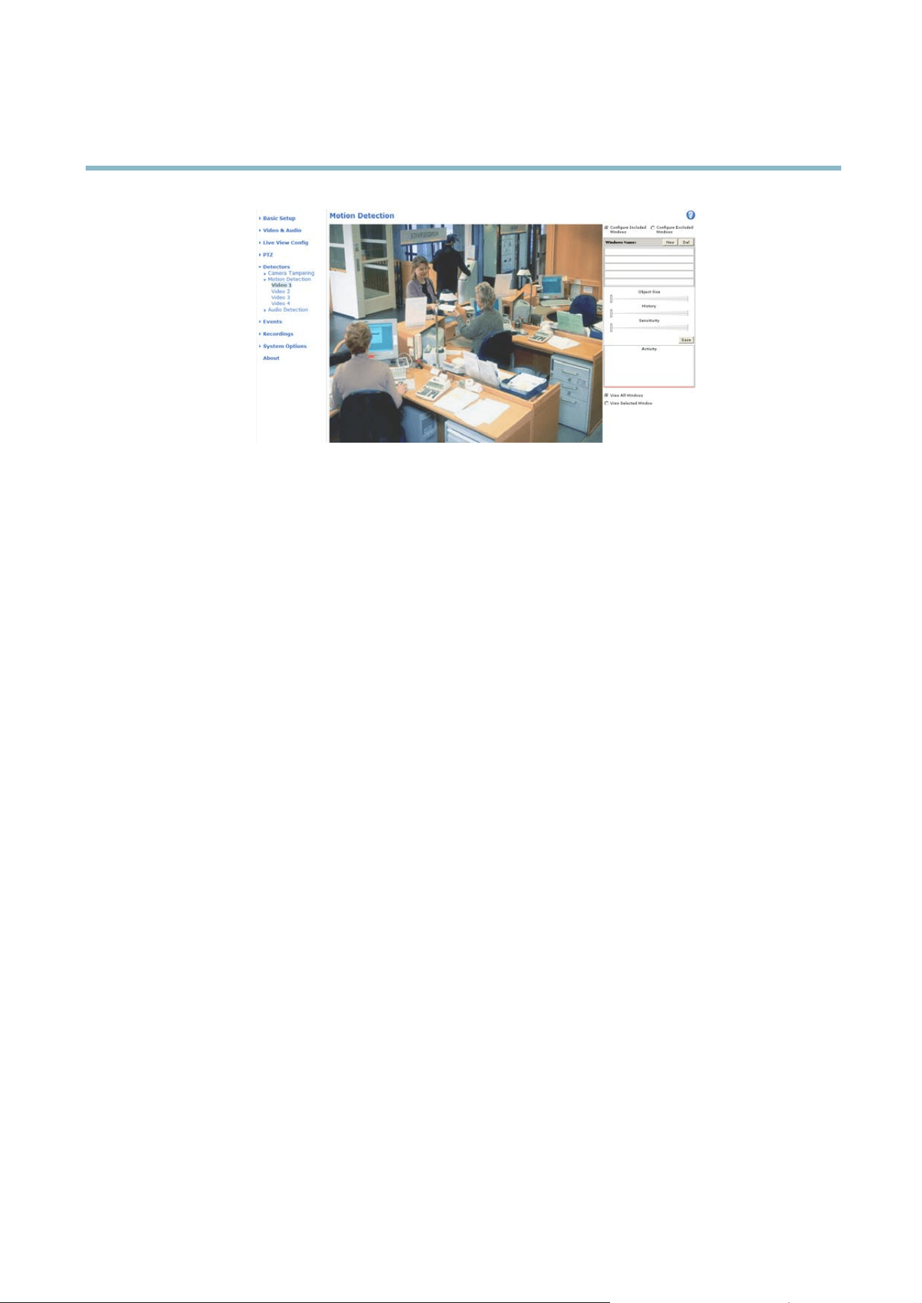
Motion Detect
ion
Motiondetectionisusedtogenerateanalarmwhenevermovementoccurs(orstops)intheview.Upto10IncludeandExclude
windows can be co nfigured:
• Include windows — target specific areas w ithin the who le video image
• Exclude windows —define areas within an Include window that should be ignored (areas outside Include windows
are automatically ignored)
Once configured, motion detection windows appear in the list of Detectors in Action rule se tup. See
Setting Up an Action Rule, on
page 32
.
Note
Using the motion detection feature may decrease the product’s overall p erf orm a nce.
29
AXIS Q7424–R
Detectors
Audio Detection
The Axis product can be configured to generate an alarm when audio rises above or falls below the threshold value. The threshold
value can be set in the range 0–100 where 0 is the most sensitive and 100 the least sensitive.
1. Go to Detectors > Audio Detection.
2. Set the audio alarm level and click Save.
3. Go to Events > Action Rules and set up an action rule, see
Setting Up an Action Rule, o n page 32
.
Detected audio is indicated by colored peaks in the Activity indicator. A n event is triggered when dete c te d audio rises above or falls
below the threshold value, which is represented by the bar.
30

AXIS Q7424–R
Events
Events
The Axis product can be configure d to perform actions whe n di ffe rent e ve nts occur, for example, start a rec ord ing w he n motion is
detected. The set of conditions that defines how and when the action is triggered is called an Action Rule.
Available Action Rule triggers and conditions include :
• Applications — use installed a pplications to trigger the r u le, see
Applications, on page 28
.
• Detectors
- Audio Detection — trigger the rule when audio is detected, see
Audio Detection, on page 30
.
- Motion Detection — trigger the rule when motion is detected, see
Motion Detection, on page 29
.
- Tampering — trigger the rule when tampe ring is detected, see
Camera Tampering, on page 29
.
• Hardware
- Video Signal — trigger the rule if video s ignal is lost.
- Network — trigger the rule if network connection is lost o r restored. This can for example be used to start
recording to the SD card.
• Input Signal
- Digital Input Port — trig ger the rule when an I/O port receives a signal from a connected device, see
I/O
Ports, o n page 44
.
- Manual Trigger — trigger the rule using the Manual Trigger button in the Live View page, see
Controls on the
Live View Page, on page 9
. This can for example be used to validate actions d
uring pro duct installation
and configuration.
• PTZ
- Moving — trigger the rule when the cam era view m oves due to a PTZ operation. This can for example be used
as an additi onal condition to prevent an action rule triggered by motion detectio n to record video while the
camera view m oves due to a P TZ operation.
- Preset Reached —triggertheru
le when the camera stops at a preset position. This can be for example be used
with the Send Images action to upload images from the preset position.
• Storage
- Available — trigger the rule when the storage device is unmounted or removed. This can for example be
used to send maintenance no tifications.
- Full — trigger the rule when the s torag e device is full. Under normal opera tion, the oldest recor dings will be
overw
ritten to prevent the storage de vice from becoming full.
- L
ocked — trigger the rule if the storage device is locked (write protected).
- Storage read only —thefile system is broken or the lock switch on the SD card is in locked position
• System
- System Initializing — trigger the rule when the product is being starte d. This can for example be used to send a
notification when the pro duct restarts.
• Time
- Recurrence — trigger the rule periodically, see
Recurrences, on page 33
. This can for example be used to
upload an image eve ry 5 minutes.
31

AXIS Q7424–R
Events
- Use Schedule — tr igger the rule according to the selected schedule , see
Schedules, on page 33
.
Available actions include:
• Output Port — activate an I/O port to control an external device.
• Play Audio Clip —see
Audio Clips, on page 21
.
• PTZ Control
- Preset Position — go to a preset position.
- Guard Tour — start a guard tour, see
Guard T our, on page 26
.
• Record Video — record video to a selected storage.
• Send Images —sendimagestoarecipient.
• Send Notifications —sendanotifi catio n message to a recipient.
• Status LED — flash the LED indicator. This can fo r example be used to validate triggers such as motion detection d uring
product installation a nd configuration.
Setting Up an Action Rule
An action rule defines the conditions that must be met for the product to perform an action, for example record video or send email
notifications. If multiple conditions are d efined, all must be met to trigger the action.
The following example describes how to set up an action rule to record video to a network share if there is movement in the
camera’s field of view.
Set up motion detection and a dd a network share:
1. Go to Detectors > M otion Detection and configure a m otion detection window, see
2. Go to System Options > Storage and set up the network share, see
page 44
.
Set up the action rule:
1. Go to Events > Action Rules and click Add.
2. Select Enable rule and enter a descriptive name for the rule.
3. Select Detectors from the Trigger drop-d own list.
4. Select M otion Detection from the drop-down list. Select the m otion detection window to use.
5. Optionally, select a Schedule and Additional conditions,seebelow.
6. Under Actions, select Record Video from the Type drop-down list.
7. Select a Stream profile and configure the Duration settings as described below .
8. Select Network Share from the Storage drop-down list.
To add additional criteria, s e lect the Additional conditions option and add additional triggers. To preve nt an action from being
triggered repeatedly, a Wait at least time can b e set. Enter the time in hours, minutes and seconds, during which the trigger
should be ignore d before the action rule ca n be activated again.
The recording Duration of some actions can be set to include time immediately before and after the event. Select Pre-trigger time
and/or Post-trigger time and enter the number of seconds. When W hile the rule is active is enabled and the action is triggered
again during the post-trigger time, the recording time w ill be extended w ith another post-trigger time period.
For m ore information, see the online help
.
32

AXIS Q7424–R
Events
Recipients
Recipients receive media files and notification messages. The following recipients are available:
Recipient Use with action
Email
Send Images
Send Notification
FTP
Send Images
HTTP
Send Images
Send Notification
Network Share Send Images
TCP Send Notification
To add a recipient:
1. Go to Events > Recipients and click Add.
2. Enter a descriptive name
3. Select a recipient Type.
4. Enter the information needed for the recipient type.
5. Click Test to test the connection to the recipient.
6. Click OK.
Schedules
Schedules can be used as action rule triggers or as additional conditions, for example to record video if motion is detected outside
office hours. Use one of the predefined schedules or create a new schedule as described below .
To create a new schedule:
1. Go to Events > Schedules and click Add.
2. Enter a descriptive n ame and the informatio n needed for a daily, weekly, monthly or yea rly schedule.
3. Click OK.
To use the schedule in an Action Rule, select the schedule from the Schedule drop-dow n list in the Actio n Rule Setup page.
Recurrences
Recurrences are use d to trigger Action Rules repeatedly, for ex am ple every 5 m inutes or every hour.
To set up a recurrence:
1. Go to Events > Recurrences and click Add.
2. Enter a descriptive name and recurrence pattern.
3. Click OK.
To use the recurrence in a n Action Rule, first se lect Time from the Trigger drop-do wn list in the Action Rule Setup page and
then select the recurrence from the second drop-down list.
33

AXIS Q7424–R
Events
To modify or remove recurrences , sele ct the recurr ence in the Recurrences List and click Modify or Remove.
34

AXIS Q7424–R
Recordings
Recordings
TheAxisproductcanbeconfigured to record video continuously or according to an action rule:
• To start a continuous recording, see
page 35
.
• To set up ac tion rules, see
page 32
.
• To access recordings, see
Recording List, on page 35
.
•Toconfigure camera controlled s torage, see
Storage, on page 43
.
Recording List
Recorded videos are listed on the Recordings > List page. The list shows each recor ding’s start date and tim e, duration and the
event that triggered the recordi ng.
To play or download a recording, follow these steps:
1. Go to Recordings > List.
2. Use the filter to narrow the lis t of recordings. Enter the desired filter criteria and click Filter. Some filters may take
a long time to complete.
3. Select the recording.
4. Click Play to play the recording, or click Download to download the recording.
Multiple recordings can be downloaded at the same time. Select the recordings and click Download. The downloaded file is a zip file
containing a minimum of three files, of which the Matroska (mkv) filesaretheactualrecordings.The recordings are time-stamped
with the date and time they w ere dow nloaded (tha t is, not the date the
recordings were made).
Note
To play record ings in W indow s Media Player, AXIS Matroska File Splitter must be installed. AXIS Matroska File Splitter
can be downloaded f rom www.axis.com/techsup/software
For detailed r ecor ding and video information, select a recording and click Properties.
To remove a recording, select the r ecord ing and click Remove.
Continuous recording
The Axis product can be configured to continuo usly save video to a storage device. See
Storage, on page 43
for more information
about storage devices. To prevent the disk from becoming full, it is recommended to configure the disk to automatically remove
old recordings.
To start a continuous recording, follow these steps:
1. Go to Recordings > Continuous.
2. Select Enabled.
3. Select type of storage device from the Disk list.
4. Select a Stream profile to use for continuous recordings.
5. Click Save to save and start the recording.
35

AXIS Q7424–R
Recordings
Note
If a n ew stream profile is selected while a recording is ongoing, the recording will be stopped and saved in the recording list
and a new recording with the new stream profile will start. All previous continuous recordings w ill remain in the recording
list until they are removed manually or through autom a tic removal of old reco rdings .
36

AXIS Q7424–R
System Options
System Options
Security
Users
User access control is enabled by default and can be configured under System Options > Security > Users. An administrator can
set up other users by giving them user names and passwords. It is also possible to allow anonymous viewer login, which means
that anybody may access the Live View page .
The use r list displays authorize d users and u se r groups (access l evels):
Viewer - Access to the Live View page
Operator - Access to the Live View page and to all settings except System Options
Administrator - Unrestricted access to all settings; can add, modify and remove other users.
Under HTTP/RTSPPasswordSettings, select the type of password to allow. You may need to allow unencrypted passwords if there
are viewing clients that do not support encryption, or i f you upgraded the firmware and existing clients support encryption but need
to log in again and be c onfiguredtousethisfunctionality.
Under User Settings, select the Enable anonymous viewer login option to allow anonymous users access to the Live View page.
Select the Enable anonymous PTZ control login to allow anonymous users access to the PTZ controls.
Deselect the Enable Basic Setup option to hide the Basic Setup menu. Basic Setup provides quick access to setting s that should be
made b efo re using the Axis product.
ONVIF
ONVIF (Open Netw ork Video Interface Forum) is a global interface standard that makes it easier for en d users, integrators, consultants,
and ma nufactur ers to take advantage of the possibiliti es offered by network video technology. ONVIF enables interoperablity between
different vendor products, increased flexibility, red
uced cost and future-proof systems.
By creating a user you automaticall
y enable O NVIF communication. Use the user name and password with all ONVIF communication
with the product. For more information see www.onvif.org
IP Address Filter
IP address filtering is enabled on the System Options > Security > IP Address Filter page. Once enabled, the listed IP address are
allowed or denied acces
s to the Axis product. Select Allow or Deny from the list and click Apply to enable IP address filtering.
The administr
ator can add up to 256 IP address entries to the list (a single entry can contain multiple IP address es).
HTTPS
The Axis product supports encrypted brow s ing using HTTPS. This is configured on the System Options > Security > HTTPS page.
A self-sig n ed cer tificate can be used until a Certificate Authority-issued certificate has been obtained. Click Create self-signed
certificate to install a self-signed certificate. Although self-signed certificates are free and offer some protection, true security is only
implemented after the installation of a signed certificate issu ed by a Certificate Authority.
To obtain a s igned certificate from an issuing Certificate Authority, click Create Certificate Request. When the signed certificate
is returned, c lick Install signed c ertificate to import the certificate. The properties of any certificate request currently resident in
the product or installed can be viewed by clicking Properties.
To enable HTTPS in the Axis product, the HTTPS Connection Policy must be set for each user group.
For m ore information, see the online help
.
37

AXIS Q7424–R
System Options
IEEE 802.1X
IEEE 802.1X is a standard for port-based Network Admission Control providing secure authentication of wired and wireless network
devices. IEEE 802.1X is based on EAP (Extensible A uthentication Protocol).
To access a network protected by IEEE 802.1X, devices must authenticate themselves. The authentication is performed by a
third-party entity called an authentic ation server, typically a RADIUS server, examples of which are FreeRADIUS and Microsoft
Internet Authentication Service.
In Ax is' implem enta tion, the netw ork device and the authentication server authenticate themse lves with the h elp of dig ital
certificates using EAP-TLS (Extensible Authentication Protocol - Transport Layer Security). The certificates a re provided by an
Certification Authority (CA ). You need:
•aCAcertificate to validate the identity of the authentication server
• a CA-signed c lient certificate and a private key to authenticate the network device.
To allow the network d evice to access a network protected by IEEE 802.1X:
1. Obtain a CA certificate, a client certificate and a client private key (contact your network administrator).
2. Go to Setup > System Options > Security > IEEE 802.1X and upload the CA certificate, the client certificate and the
client private key.
3. Under Settings, select the EAPOL version, provide your EAP identity and private key password.
4. Check the box to enable IEEE 802.1X and click Save.
Certificates
CA Certificate The CA certificate is used to va lida te the identity of the authentication s erver. Enter the path to
the certificate directly, or lo cate the file using the Browse button. Then click U
pload.Toremove
acertificate , click Remove.
Client certificate
Client private key
The clie nt certificate and private key are used to authen tica te the network device. They can be
uploaded as se par ate files or in one combined file (e.g. a PFX file or a PEM file). Use the Client
private key field if uploading one combined file . For each fi le, enter the path to the file
, or locate the
file using the Browse button. Then click Upload.Toremoveafi l e, click Remove.
Settings
EAPOL version
SelecttheEAPOLversion(1or2)asusedinyournetworkswitch.
EAP identity
Enter the user identity (maximum 16 characters) associated with your certificate.
Private key password
Enter the password (maximum
16 characters) for the private key.
Enable IEEE 802.1X
Check the bo x to enable the IEEE 802.1X protocol.
Audio Support
Select Enable audio support to allow clients to retrieve audio stre am s fro m t he Ax is product. For info rm ati on on how to configure
audio setting s, see
Audio Settings, on page 19
.
Note
Deselecting this option will dis ab le audio globally in the Axis product, for config ured events and profiles with audio as well.
Date & Time
The Axis product’s date and time s ettings are configured under System Options > Date & Time.
Current Server Time displays the current date and time (24h clock). The time can be displayed in 12h clock in the text overlay (see
below).
38

AXIS Q7424–R
System Options
To change the date and time setting s, select the preferred Time mode under New Server Time:
• Synchronize with computer time sets date and time according to the computer’s clock. With this option, date and
time are set once and will not be upd ated automatically.
• Synchronize with NTP Server o btains date and time from a n NTP server. With this option, date and time settings are
updated continuously. For information on NTP settings, see
NTP Configuration, on page 40
.
If using a host name for the NTP server, a DNS server must be configured. See
DNS Configuration, on page 40
.
• Set m anually a llow s you to manually set date a n d time.
If using an NTP server, select your Time zone from the drop-down list. If required, check Automatically a djust for daylight saving
time changes.
The Date & Time Format Used in Images is the date and time format displayed as a text overlay in the video stream. Use the
predefined formats or see
File Naming & Date/Time Formats
in the online help for information on how to create custom date and
time formats. To include date and time in the overlay text, go to Video & Audio and select Include date and Include time.
Network
Basic TCP/IP Settings
The Axis product supports IP version 4 and IP version 6. Both versions can be enabled simultaneously, and at least one version
must always be enabled.
IPv4 Address Configuration
By default, the Axis product is set to use IPv4 (IP version 4) and to obtain the IP ad dress automatically via DHCP. The IPv4 settings are
configured under System Options > Network > TCP/IP > Basic.
DHCP (Dynamic Host Configuration Protocol) allows network administrators to centrally mana ge and automate the assignment of
IP addresses. DHCP should only be enabled if using dynamic IP address notificatio n , or if the DH C P can update a DNS server. It is
then possible to access the Axis product by name (host name).
If DHCP is enabled and the p roduct cannot be accessed, run AXIS IP Utility to search the netwo rk for connected Axis products, or reset
the product to the factory default settings (see
page 47
) and then perform the installation again.
To use a static IP address, check Use the following IP address and specify the IP address, subnet mask and default router.
IPv6 Address Configuration
If IPv6 (IP version 6) is enabled, the Axis product w ill receive an IP address according to the configuration in the network router.
To enable IPv6, go to System Options > Network > TCP/IP > Basic. Other settings for IPv6 should be configured in the network router.
ARP/Ping
The IP address can be set using ARP and Ping . For instructions, see the product’s Installation Guide.
ARP/Ping is enabled by defau lt. To d isa ble , uncheck the box under System Options > Network > TCP/IP > Basic.
The A RP/ Ping service is a u tomatically disabled two minute s after the product is started, or as soon as an IP address is set. T o reset the
IP address, the product must be restarted to activate ARP/Ping for an additional two minutes.
Pinging the product is still possible when this service is disabled.
39

AXIS Q7424–R
System Options
AXIS Video Hosting System (AVHS)
AVHS used in conjunction with an AVHS service, provides easy and secure Internet access to live and recorded video accessible from
any location. For more information and help to find a local AVHS Service Provider go to www.axis.com/hosting
AVHS is enabled by d efa u lt. The s ettings are configured under System Options > Network > TCP IP > Basic.
One-click enabled - Press the product’s control button (see
Hardware Overview, on page 5
) to connect to an AVHS service over the
Internet. Once registered, Always will be enabled and the Axis product stays connected to the AVHS s ervice. If the product is not
registered within 24 hours from when the button is pressed, the product w ill disconnect from the AVHS service.
Always - The Axis product will constantly attempt to connect to the AVHS service over the Internet. Once registered the product will
stay connected to the service. This option can be used when the pro duct is already installed and it is not convenient to use the
one-click installa tion.
AXIS Internet Dynam ic DNS Service
AXIS Internet Dynamic DNS Service assigns a host name for easy access to the product. For more information, see www.axiscam.net
To register the A xis product with AXIS Interne t Dynamic DNS Se rvice , go to System Op tions > Network > TCP/IP > Basic.Under
Services, click the AXIS Internet Dynamic DNS Service Settings button (requires access to the Internet). The domain name currently
registered at AXIS Internet Dynamic DNS serv ice fo r the product can at any time be removed.
Advanced TCP/IP Settings
DNS Confi guration
DNS (Domain Name Service) provides the translation of host names to IP addresses. The DNS settings are configured under System
Options > Network > TCP/IP > Advanced.
Select Obtain D NS server address via DHCP to use the DNS settings provided by the DHCP server.
To make manual settings, select Use the following DNS server address and specify the following:
Domain name - Enter the domain(s) to search for the host n ame used by the Axis product. Multiple do m ains ca n be separated by
semicolons. The host nam e is always the firstpartofafullyqualified domain name, for example, myserver is the host name in the
fully qualified domai n name myserver.mycompany.com where mycompany.com is the domain name .
Primary/Secondary DNS server - Enter the IP addresses of the primary and secondary DNS server s. The seconda ry DNS server is
optional a nd will be used if the primary is unavailable.
NTP Configuration
NTP (Network Time Protocol) is used to synchronize the clock times of devices in a network. The NTP settings are configured under
System Options > Network > TCP/IP > Advanced.
Select Obtain NTP server address via DHCP to use the NTP setting s provided by the DHCP server.
To make manual settings, select Use the following NTP server address and enter the host name or IP address of the NTP server.
Host Name Configuration
The Axis product can be accessed using a host name instead of an IP address. The host name is usually the same as the assigned DNS
name. The ho st name is configured under System Options > Network > TCP/IP > Advanced.
Select Obtain host name via IPv4 DHCP to use host name provided by the DHCP server running on IPv4.
Select Use the host name to set the host name manually.
Select Enable dynamic DNS updates to dynamically update local D N S servers whene ver the Axis prod uct’s IP address changes.
For m ore information, see the online help
.
40

AXIS Q7424–R
System Options
Link-Local IPv4 Address
Link-Local Address is enabled by default and assigns the Axis product an additional IP address whichcanbeusedtoaccess
the product from other hosts on the same segment on the local network. The product can have a Link-Local IP and a static
or DHCP-supplied IP address at the same tim e .
This function can be disable d under System Options > Network > TCP/IP > Advanced.
HTTP
The HTTP port u sed by the Axis product can be changed under System Options > Network > TCP/IP > Advanced. In addition to the
default setting, w hich is 80, any port in the range 1024–65535 can be used.
HTTPS
The HTTPS port used by the Axis product can be changed under System Options > Network > TCP/IP > A dvanced. In addition to
the default setting, which is 443, any port in the range 1024–65535 can be used.
To enable HTTPS, g o to System Options > Security > HTTPS. For more information, see
page 37
.
NAT traversal (port mapping) for IPv4
A network router allows devices on a private network (LAN) to share a single connection to the Internet. This is done by forwarding
network traffic from the private network to the “outside”, that is, the Internet. Security on the private network (LAN) is increased
since most routers are pre-configured to stop attempts to access the private network (LAN) from the public network (Internet).
Use NAT traversal w he n the Axis product is located on an intranet (LAN) and you wish to make it available from the other
(WAN) side of a NAT router. With NAT travers al properly configured, all HTTP traffic to an external HTTP port in the NAT router
isforwardedtotheproduct.
NAT tra ve rs al is configured under System Options > Network > TCP/IP > A dvanced .
Note
• F or NA T tra vers al to w ork, this mus t be supporte d by the ro uter. The router m ust also support UPnP
TM
.
• The router has many different name s: “NAT router”, “Network router”, “Internet Gateway”, ”Broadband router”, “Broadband
sharing device” or “Home firewall” but the essential purpose of the device is the sa
me.
Enable/Disable - When enabled, the Axis product attempts to configure port mapping in a NAT router on your network, using UPnP
TM
.
Note that UPnP
TM
must be enabled in the product (see System O ptions > Network > UPnP).
Use manua lly selected NAT router - Select this option to manually select a N AT router and enter the IP ad dress for the ro uter in
the field. If no router is specified, the pro duct automatically searches for NAT routers on yo ur network. If more than one router is
found, the default router is selected.
Alternative HTTP port - Select this option to manually define an external HTTP port. Enter the port num ber in the field. If no port is
entered he re , a port number is autom a t ically selected whe n NAT trave rs al is enable d.
Note
• An alternative HTTP port can be used or be active even if NAT traversal is disabled. This is useful if your NAT router does
not support UPnP and you need to manually configure p ort for wa rding in the NAT route r.
• If you attempt to man
ually enter a port that is alre ady in use, anothe r available port is automatica lly sele cte d.
• When the port is selected autom atically it is displayed in this field. To change this, enter a new port number and click Save.
FTP
The FTP server running in the Axis product enables upload o f new firmware, u se r a pplications, etc. The FTP server can be disabled
under System Op tions > Network > TCP/IP > Advanced.
41

AXIS Q7424–R
System Options
Note
This FTP server h as nothing to do with the product’s abil ity to transfer images via FTP to other l ocations and servers.
RTSP
The RTSP server running in the Axis product allows a connecting client to start an H.264 stream. The RTSP port number can be
changed under System Options > Network > TCP/IP > Advanced. The default port is 554.
Note
H.264 video streams will not be available if the RTSP server is disabled.
SOCKS
SOCKS is a networking proxy protocol. The Axis product can be confi gured to use a SOCKS server to reach networks on the other
side of a firewall or proxy server. This functionality is useful if the A xis product is located on a local network behind a firewall, and
notifications, uploads, alarms, etc need to be send to a destination outside the local network (for example the Internet).
SOCKS is configured under System Options > Network > SOCKS. For more informatio n, see the online help
.
QoS (Quality of Service)
QoS (Quality of Service) guarantees a certain level of a specified resource to selected traffic on a network. A QoS-aware network
prioritizes network traffic and provides a greater network reliability by co ntrolling the amount of bandwidth an application may use.
The QoS settings are configured under System Options > Network > QoS. Using DSCP (Differentiated Services Codepoint) values, the
Axis product can mark the following types of traffic: live video, live audio, event/a larm traffic and management traffic.
Note
Live audio DSCP will be eq ual to live video DSCP if H.264 over RTSP is used.
SMTP (email)
To send email messages from the Axis pro duct via SM TP (Simple Mail Transfer Protocol), an SMTP mail server must be set up. This
is done under System Options > Network > SMTP (email).
Enter the host names or IP addresses and port numbers for the primary and secondary mail servers in the fields provided . A From
email address is a lso required . If the ma il server requires a
uthentication, check Use authentication to log in to this server and enter
the necessary information.
SNMP
The Simple Network Ma nag ement P rotocol (SNMP) allows remote management of network devices. An SNMP community is the
group of d evices and management stati
on running SNMP. Community names are used to identify groups.
The Axis product can be configured
to support SNMP on the System Options > Network > SN MP page.
Depending on the level of sec
urity required, select the version on SNMP to use.
SNMP v1/v2 provides the
lowest level of security. The community name can be specified as a password for re ad or re ad/write
access to all supported SNMP devices. The default password for the Read community is public and the default password for the
Write community is write.
Note
If HTTPS is enabled, SNMP v1 and SNMP v2c should be disabled.
Traps for SNMP v1/v2 are used by the Axis product to send messages to a management system on important events and status
change
s. Check Enable traps and enter the IP address where the trap message should be sent and the Trap community that
should receive the message.
42

AXIS Q7424–R
System Options
The following traps are available:
•Coldstart
•Warmstart
•Linkup
• Authentication failed
SNMP v3 provides encryption and secure passwords. To use traps with SNM P v3, an SNMP v3 management application is required.
To use SNMP v3, HTTPS must be enabled, see
HTTPS, on page 37
. To enable SNMP v3, check the box and provide the initial user
password.
Note
The initial password can only be set once. If the password is lost, the Axis prod uct must be reset to factory default, see
Reset to Factory Default Settings, on page 47
.
UPnP
TM
The Axis product includes supp ort for UPnP
TM
.UPnP
TM
is enabled by default and the product is automatically detected by operating
systems and clients that support this protocol.
UPnP
TM
can be disable d under System Options > Network > UPnP
TM
.
RTP/H.264
The RTP port range and multicast settings are co nfig u red under System Options > Network > RTP.
The RTP port range defines the range of ports from which the video/audio ports are auto
matically selected. For m ulticast streams,
only certain IP addresses and port numbers should be used.
Select Always Multicast Video and/or Always Multicast Audio to start multica st stream i n g witho ut open ing an RTSP session.
Bonjour
The Axis product includes support for Bonjour. Bonjour is enabled by default and the product is automatically detected by operating
systems and clients that support this protoc
ol.
Bonjour can be disabled under System Op
tions > Network > Bonjour.
Storage
SD Card
NOTICE
To prevent corruption of recordings, the SD card should always be unmounted b efore it is ejected.
The Axis product supports SD cards with the fo llow ing file systems:
• ext4 — re com m e nde d due to its resilience against data loss if the card is ejected or if there is abrupt power loss. To access
data stored on the card from the Windows operating system, a third-party ext4 driver or application is required.
• vFAT — most SD cards are pre-formatted with vFAT when purchased.
If required, the SD card can be re-formatted to the desired file system . To format the SD card:
1. Insert the SD card in the SD card slot.
2. Go to System Options > Storage an d click SD Card.
43

AXIS Q7424–R
System Options
3. Click Format and select the desired file system.
Note
During formatting any previous d ata stored on the disk wi ll be lost.
Mounting is done automatically when the card is inserted or whe n the product is started. A manual mount is only required if the
card has been unmounted and not ejected and re-inserted.
To unmount the SD card:
1. Go to System Options > Storage an d click SD Card.
2. Click Unmount.
3. The card can now be ejected.
The SD card is managed on the System Options > Storage page. Click SD Card to o pen Storage M anagement.
If the card’s status shows as fa ile d, click Check disk to see if the problem can b e fo und and then try Repair. This op tion is only
available for SD cards with ext4. For SD cards with vFAT, use a card reader or computer to troubleshoot the card.
To avoid filling the card, it is recommended to remove recordings continuously. Under Recording Settings, select Remo ve recordings
older than and select the number of days or weeks.
To stop writing to the card and protect recording s from being removed, select Lock under Recording Settings.
Network Share
Network share allows you to add network storage such as a NAS (Network Attached Storage) or any server that uses CIFS (Common
Internet File System) and use them for storage of recordings.
To add a network share:
1. Go to System Options > Storage.
2. Click Network Share.
3. Enter the IP address, DNS or Bonjour name to the host server in the Host field.
4. Enter the name of the share in the Share fi el d.
5. If required, select The share requires login and enter the user name and password.
6. Click Connect.
To clear all r ecordings and data from the Axis product’s folder on the designated share, click Clear under Storage T ools.
To avoid filling the share, it is recommended to remove recordings continuously. Under Recording Settings,selectRemove recordings
older than and select the number of days or weeks.
To stop writing to the share and protect recordings from being removed, select Lock under Recording Settings.
Ports & Devices
I/O Ports
The Axis product provides four configurab le input and output ports for connection o f exte rna l device s. For information on how to
connect external devices, see
Connectors, on page 5
.
The I/O ports are configured under System Options > Ports & Devices > I/O Ports. Select the port dire ction (Input or Output). The
ports can be given descriptive names and their Normal states can be confi gured as Open circuit or Grounded circuit.
44

AXIS Q7424–R
System Options
COM P or t
The video encoder has one RS-485/RS-422 serial port. The port supports the following modes:
• Generic HTTP allows the video encoder to receive data and send commands via HTTP.
• Pan T ilt Zoom is used to control a PTZ device. The PTZ device req u ire s a d r iver. See
Installing a P TZ driver
for more
information. Drivers can be downloaded from www.axis.com
• Generic TCP/IPallows the Axis prod u ct to receive data and send commands via TCP/IP. Da isy cha in server - Allows Daisy
chain clients to communicate with the Axis product. See also RS-485/RS-422 connector, on page 43.
Select the desired Port Type from the drop-down list. For more information on Serial Port Settings and Daisy Chain Port Settings
seetheonlinehelp
.
Port Status
The list on the System Options > Ports & Devices > Port Status page shows the status of the product’s input and output ports.
Maintenance
The Axis product provides several maintenance functions. These are available under System Options > Maintenance.
Click Restart to perform a co rrect restart if the Axis product is not behaving as expected. This will not affect any of the current
settings.
Click Restore to reset most settings to the factory default values. The following settings are not affected:
• the boot pro tocol (DHCP or static)
• the static IP addr ess
• the default router
• the subnet mask
•thesystemtime
• the IEEE 802.1X settings
Click Default to reset a ll settings, including the IP address, to the factory default values. This button should be u sed with caution. The
Axis product can also be re se t to factory default using the control button, see
Reset to Factory Default Settings, on page 47
.
To identify the product or test the Status LED, click Flash LED under Identify and specify the duration in seconds, minutes or hours.
This can be useful for identifying the p roduct am ong other products installed in the same locati on.
For information about firmware upgrade, se e
Upgrading the Fi rm ware, on page 48
.
45
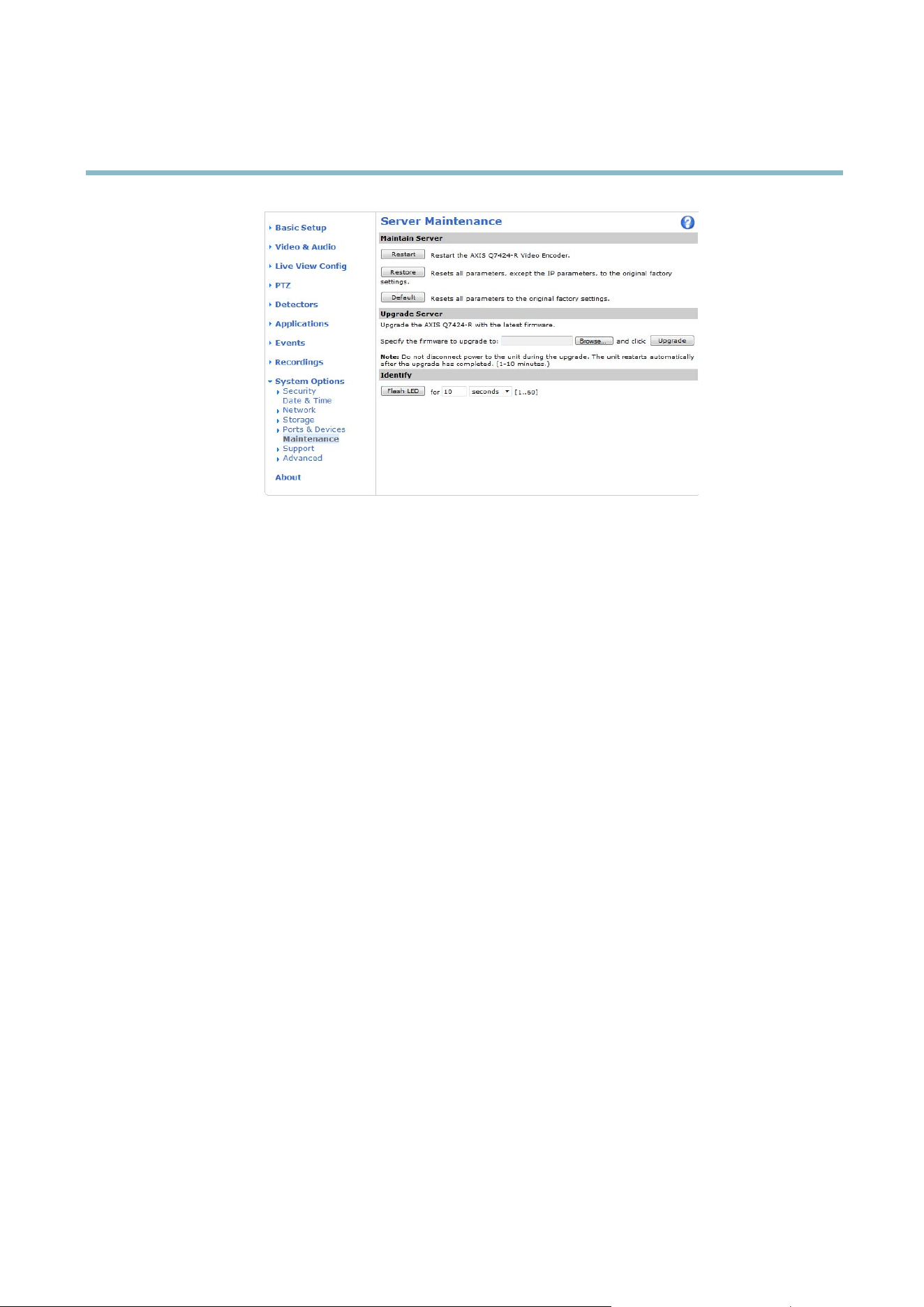
AXIS Q7424–R
System Options
Support
Support Overview
The System Options > Support > Support Overview page provides information on troubleshooting and contact information,
should you require technical assistance.
See a lso
Troubleshooting, on page 48
.
System Overview
To get a n overview of the Axis product’s status and settings, go to System Options > Support > System Overview. Information that
can be found here includes firmware version, IP address, network and security settings, event settings, image settings and recent log
items. Many of the captio ns are links to the proper Setup p age.
Logs & Reports
The System Options > Support > Logs & Reports page generates logs and reports useful for system analysis and troubleshooting. If
contacting Axis Support, please provide a valid S erve r Report with your query.
System Log - Provides info rmation about system e vents.
Access Log - L ists a ll failed attempts to access the product. The Access Log can also be configured to list all connections to the
product (see below).
Server Report - Provides information about the product status in a pop -up window. The Access Log is autom a tically included
in the Server Report.
You can view or download th
e server report. Downloading the server report creates a .zip file that contains a complete server report
text file in U TF–8 f orm a t. Select the Include snapshot with default image settings option to include a snapshot of the product’s
Live View that also shows the settings specified under Video Stream>Image>Im age Appearance. The server report .zip file should
always be include
dwhencontactingsupport.
Parameter L is
t-Shows the product's parameters and their current settings. This may prove useful when troubleshooting or
when contacting Axis Suppo rt.
Connection List - Lists a ll clients that are currently a c ce s sing media stream s.
Crash Report - Ge nerate s an archive with de bugging inform a tion. The report takes several minutes to generate.
46

AXIS Q7424–R
System Options
The log levels for the System Log and the Access Log are set under System Options > Support > Logs & Reports > Configuration.
The Access Log can be config u red to list all connections to the product (select Critical, Warning s & Info). If required, a different log
level can be used wh e n sending emails.
Advanced
Scripting
Scripting allow s experienced users to customize and us e their o wn scripts.
NOTICE
Improper use may cause unexp ected behavio r and loss of contact w ith the Axis product.
Axis strongly recomm ends that you do not use this function unless you understand the consequences. Axis Support does not provide
assistance for problems w i th cu stomized scripts.
To open the Script Editor, go to System Options > Advanced > Scripting. It is recommended to create a backup file before
customizing the scripts. If a script causes problem s , reset the product to its f actory defa ult s ettings , see
page 47
.
For more information, see www.axis.com/developer
File Up load
Files, for example web page s and images, can be uploaded to the Axis product and used as custom settings. To upload a file , go
to System Options > Advanced > File Upload.
Uploaded files are accessed through http://<ip address>/local/<user>/<file name> where <user> is the
selected user group (viewer, operator or administrator) for the uploaded file.
Plain Config
Plain Config is for advanced users with experience of Axis product configuration. Most parameters can be set and modified from this
page. Help is a vailable fro m the standard help pages.
To open Plain Config, go to System Option s > Advan c ed > Plain Config .
Reset to Factory Default Settings
This will re se t all param ete rs , including the IP address, to the factory default settings :
1. Disconnect power from the product.
2. Press and ho ld the C ontrol button and reconnect power (see
Hardware Overview, on page 5
).
3. Keep the Control button pressed for about 15 seconds until the Status indicator flashes amber.
4. Release the Control button. The process is complete after about 1 minute (when the Status indicator turns green). The
product has been reset to the factory default settings. The default IP address is 192.168.0.90
5. Re-assign the IP address.
It is also possible to reset parameters to fa ctory default via the web interface. Go to Setup > System Options > Maintenance.
47

AXIS Q7424–R
Troubleshooting
Troubleshooting
Checking the Firm ware
Firmware is software that determines the functionality of network devices. One of your first actions w hen troubleshooting a problem
should be to check the current firmware version. The latest version may contain a correction that fixesyourparticularproblem.The
current firmware version in the A xis prod uct is displa yed in the page Setup > Basic Setup and in Setup > About.
Upgrading the Firmware
When you upgrade the product with the latest firmw a re fr om Axis website, the product receives the late st functiona lity available.
Always read the upgrade instructions and release notes available with each new release, before upgra ding the firmware.
To upgrade, follow these instructions:
1. Save the firmware file to your computer. The latest version of the fir mware is available free of cha rge from Axis website
at www.axis.com/techsup
2. Go to Setup > System Options > Maintenance in the products web pages.
3. Under Upgrade Server, c lick Browse and locate the file on your computer. Click Upgrade.
After starting the upgrade process, a lways wait at least 5–10 minutes before restarting the product, even if you suspect the
upgrade has failed.
AXIS Camera Management can be us ed f or m ultiple upgrades. See www.axis.com for more information.
Note
• Your dealer reserves the right to charge for any repair attributable to faulty upgrade by the user.
•Preconfigured and customized settings are saved when the firmw are i s upgraded
(providing the features are available in
the new firmware) although this is not guaranteed b y Axis Com m unicatio n s AB.
Emergency Recovery Procedure
If power or network connection is lost during the upgrade, the process fails and the product becomes unresponsive. Flashing red Status
indicator indicates a failed upgrade. To recover the product, follow the steps below. The serial number is found on the product’s label.
1. In UNIX/Linux, type the following from the command line:
arp -s <IP address> <serial number> temp
ping -s 408 <IP address>
In Windows,typ
e the following from a command/DOS prompt (this may require that you run the command prompt as
an admin istra tor):
arp -s <IP address> <serial number>
ping -l 408 -t <IP address>
2. If the p roduct does not rep ly in 30 seconds, restart it and wait for a reply. Press CTRL+C to stop Ping.
3. Open a browser and type in the product’s IP address. In the page that appears, use the Browse button to select the upgrade
file to use. Then click Load to restart the upgrade process.
4. After the upgrade is complete (1–10 minutes), the product automatically restarts and shows a steady green on the Status
indicator.
5. Reinstall the product, referring to the Installation Guide.
If the emergency recovery procedure does not get the product up and running again, contact Axis support at www.axis.com/techsup/
48

AXIS Q7424–R
Troubleshooting
Symptoms, Possible Causes and Rem edial Actions
Problems setting the IP address
When using ARP/Ping
Try the installation again. The IP address must be set within two minutes after power has been
applied to the product. Ensure the Ping length is set to 408. See the Installation Guide for
detailed instructions.
The product is located on a
different s ubnet
If the IP address intended for the product and the IP address of the computer used to access the
product are located on different subnets, you will not be able to set the IP address. Contact your
network administrator to obtain an IP address.
The IP address is be ing used
by another device
Disconnect the Axis product from the network. Run the Ping command (in a Command/DOS
window, type ping and the IP address of the product:
•Ifyoureceive:Reply from <IP address>: bytes=32; time=10...
this means that the IP address may already be in use by another device on the network.
Obtain a new IP address from the network administrator and reinstall the product.
•Ifyoureceive:Request timed out , this m eans that the IP address is available for
use with the Axis product. Check all cabling and reinstall the product.
Possible IP address c onflict
with another device on the
same subnet.
The static IP address in the Axis product is used before the DHCP server s ets a dynamic ad dre ss .
This means that if the same default static IP a ddressisalsousedbyanotherdevice,theremay
be pro blems accessing the product.
The product cannot be accessed from a browser
Cannot log in
When HTTPS is enabled, ensure that the correct protocol (HTTP or H TTPS) is used when attempting
to log in. You may need to manually type http or https in the browser’s address field.
If the passw ord for root is lost, the pro duct must be reset to the factory default settings. See
Reset to Factory Default Settings, on page 47
.
The IP address has been
changed by DHCP
If the product and the client are on the same network, run AXIS IP Utility to locate the pro duct.
Identify the product using its model or serial number.
Move the A xis product to an isolated netwo rk, or to one w ith no DHCP or BOOTP server. Set the IP
address again, using AXIS IP Utility or ARP/Ping (see the Installation Guide). Open the Setup pages
and disabled DHCP in the TCP/IP settings. Return the product to the main network. The product
now has a fixed IP address that will not change.
Certificate error when using
IEEE 802.1X
For authentication to work properly, the date and time settings in the Axis product should be
synchronized with an NTP server. See
Date
& Time, on page 38
.
The product is accessible locally but not externally
Router configuration To configure your router to allow incoming data traffic to the Axis product, enable the NAT-traversal
feature which will atte m pt to automatically configure the router to a llow access to the Axis
product, see
NAT traversal (port mapping) for IPv4, on page 41
. The router must support UPnP
TM
.
Firewall protection
Check the Internet firew all with your network administrator.
Default router
srequired
Check if you need to configure the router settings.
Problems with the H.264 format
No H.264 displayed in the
client
Check that the relevant H.264 connection methods and correct interface are ena ble d in the AMC
Control Pan el (streaming tab). Se e
AXIS Media Control (AMC), on page 12
.
In the AMC Control Panel, select the H.264 tab and click Set to default H.264 decoder.
Check that RTSP is enabled under System O ptions > Network > TCP/IP > Advanced.
49

AXIS Q7424–R
Troubleshooting
No multicast H.264
displayed in the cl ient
Check with your network administrator that the multica st addresses used by the Axis product
arevalidforyournetwork.
Check with your network administrator to see if there is a firewall preventing viewing.
Multicast H.264 only
accessible by local clients
Check if your router supports multicasting, o r if the router s ettings between the client and the
product need to be config ured. The TTL (Time To Live) value may need to be increased.
Poor rendering of H.264
images
Color depth set incorrectly on clients. Set to 16–bit or 32–bit color.
If text overlays are blurred, or if there are other rendering problems, you may need to enable
Advanced Video Rend eri ng fromv the Video tab in the AMC Control Panel.
Ensure that your graphics card is using the late st driver. The lates t drivers can usually be
downloaded fro m the manufacturer’s web site.
Color saturation is diffe re nt
in H.264 and M otion JPEG
Modify the settings for your graphics adapter. Refer to the ada pter’s documentation for more
information.
Lower frame rate than
expected
Reduce the number of a pplications running on the client computer.
Limit the number of simultaneous viewers.
Check with the network administrator that there is enough band wid th availa ble.
Check in the AMC Control Panel (H.264 tag) that video processing is NOT set to Decode only
key frames.
Lower the image resolution.
Why do I not get maximum
frames per second?
See
Performance Considerations, on p age 56
.
Image degeneration
Decrease the GOV length. Go to Video & Audio > Video Stream and select the H.264 tab
to modify the GOV length.
Status and Network indicator LEDs are flashing red r
apidly
Hardware failure
Contact your Axis reseller.
Status indicator LED is flashing red and the product is inaccessible
A firmwar e upg rade h a s
been interrupted or the
firmware has otherwise been
damaged
See
Emergency Recovery P
rocedure, on pa ge 48
.
No images displayed on web page
Problems with AXIS Media
Control (
I
nternet Explorer
only
)
To enable the updating of video images in Internet Explorer, set the browser to allow A ctiveX
controls. Also, make s u re tha t AXIS Media Control is insta lle d on your computer.
Installation of additional
ActiveX component
restricted or prohibited
Configure the Axis product to use a Java applet for updating vid eo images in Internet Explorer. Go
t
o Setup > Live View Config and select Java applet under Default viewer.
Video and image problems, general
Image too dark or too light
Check the video stream and camera settings under Setup > Video & Audio > Video Stream and
Setup > Video & Aud io > Camera Settings.
Missing images in uploads This can occur when tr ying to use a larger image buffer than is actually available. Try loweri ng
the fra me rate or the upload period.
50

AXIS Q7424–R
Troubleshooting
Slow image update Configuring pre-buffe rs , m oti on de tection, high-resolution ima g es o r hig h fr am e ra tes w il l affe ct
the p erform a n ce of the Axis product.
Poor performance Poor performance may be caused by heavy netw ork traffic, multiple users acces sing the product,
low performance clients, use of features such as motion detection, event handling or uploaded
applications.
Poor quality snapshot images
Screen incorrectly
configured on your computer
Configure your screen to show at least 65000 colors, that is, at least 16 bits. Using only 16 or 256
colors will produce dithering artifacts in the image.
Overlay image is not displayed
Incorrect size or location of
overlay image
The overlay image may have been positioned incorrectly or m ay be too large. See
Overlay Image
Settings
in the online help for more inform a tion.
Privacy mask is n ot displayed
Incorrect size or location of
privacy mask
The privacy mask may have been positioned incorrectly or may be too large.
Browser freezes
Firefox can sometimes
freeze on a slow computer
Lower the image resolution
Problems uploading files
Limited space There is only limited space available for the upload of your own files . Delete existing file s t o f ree
up space.
Motion Detection triggers unexpectedly
Changes in luminance
Motion detection is based on changes in luminance in the image. This m eans that if there are
sudden changes in the lighti ng, motion de te ction may trigg er mistakenly. Lower the sensitivity
setting to avoid problems with luminance.
No audio
Incorrect setup
Check the sound card in the com pute r. E n sure that mute is not selected and that the volume
settings are correct.
No audio or very poor audio
quality
Check that Enable audio support is selected under Setup > System Options > Security > Audio
Support.
Check that the correct Audio Input source is selected under Setup > Video & Audio > Audio
Settings.
Poor audio quality
CPU overloaded
Reduce the number o f listeners and viewers. De c rea se im age resolution and compression.
Unsynchronized audio and
video
Synchronize the product’s date and timesettingswithanNTPserver. GotoSetup > System
Options > Date & Time.
51

AXIS Q7424–R
Troubleshooting
Distorted audio
Check that the correct Audio Input source is selected under Setup > Video & Audio > Audio
Settings.
Feedback loops Feedback loops might appear in full-duplex mode. Try moving the microphone or the speaker, or
use half-duplex mode instead.
Storage and disk management problems
Video cannot be recorded
Check that the SD card is not w rite protected (that is, read only).
SD card cannot be mounted Reformat the SD card and then click Mo unt.
52

AXIS Q7424–R
Technical Specifications
Technical Specifications
Function/group
Item
Specifications
Video Encoder Model
AXIS Q7424–R (4 channels)
Video
compression
H.264 (MPEG-4 Part 10/AVC) Baseline Profile (BP) and Main Profile (MP )
Motion JPEG
Resolutions
176 x 120 to 720 x 576
176 x 120 to 1536 x 1152 for quad view
Frame rate H.264
30/25 (NTSC/PAL) fps
15 fps in quad view in full resolution
Frame rate
Motion JPEG
30/25 (NTSC/PAL) fps
15 fps in quad view in full resolution
Video streaming
Multi-stream H.264 and Motion JPEG: One H.264 and one JPEG stream on each channel
(8 streams in total) in full framerate individually configured streams in max. resolution at
30/25 fps; more streams if identical o r limited in frame rate/resolution
Controllable frame rate and bandwidth
VBR/CBR H.264
Pan/Tilt/Zoom
Wide range of analog PTZ cameras supported (drivers a vailable for download at
www.axis.com)
100 presets/camera, g uard tour, P TZ control queue
Supports W indow s compatible joysticks
Video
Image settings
Compression, color, brightness, contrast
Rotation: 90°, 180°, 270°
Aspect ratio correction
Mirroring of im age s
Text and image overlay
Privacy mask Enhanced deinterlace filter
Video termination
Anti-aliasing
Temporal noise filtering
Audio streaming Two-way
Audio
compression
AAC-LC 8/16 kHz, G.711 P CM 8 kHz, G.726 ADPCM 8 kHz
Configurable bit rate
Audio
Audio
input/output
One external microphone or line inputs and one line output
Security Password protec
tion, IP address filtering, HTTPS* encryption, IEEE 802.1X netwo rk access
control, digest authentication, user access lo g
Network
Supported
protoc
ols
IPv4/v6, HTTP, HTTPS*, QoS layer 3 DiffServ, FTP, SMTP, B onjour, U PnP,
SNMPv1/v
2c/v3(MIB-II), DNS, DynDNS, NTP, RTSP, RTP, TCP, UDP, IGM P, RTCP, ICMP,
DHCP, ARP, SOCKS
53

AXIS Q7424–R
Technical Specifications
Function/group
Item
Specifications
Application
Programming
Interface
Open API for softw a re integration, including the O NVIF specification available at
www.onvif.org, as w ell as VAPIX® a nd AXIS C amera Apllication Platform from Axis
Communications, specifications available at www.axis.com
Support for AXIS Video Hosting System (AVHS) with One-Click Camera connection
Intelligent video Video motion detection, active tampering alarm, audio de tection
Support for AX IS C amera Apllicat ion Plaform on one channel
Alarm triggers Intelligent video, external inputs, video loss
System
Integration
Alarm actions File upload via FTP , HTTP and email
Notification via email, H TTP and TCP
PTZ preset
External o u tput activatio n
Video and audio r ecording to edge storage
Pre- and post-alarm video buffering
Casing Standalone aluminum casing
Processor,
memory
ARTPEC-4, 512 MB RAM, 128 MB Flash
Power
8-28 V DC, 20-24 V AC ; Power over Ethernet
IEEE 802.3af Class 3
Connectors
4x an alog compo site video inputs (BNC)
1x mono microphone or line input, 6Vpp max (terminal block)
1x mono audio output, 2Vpp max at 1kohm (terminal block)
1x 10BASE-T/100BASE-TX Ethernet
4x Configurable external inputs/outputs (terminal block)
1x RS-485/422 full dup lex (terminal block)
1x AC/DC input terminal block
1x 1 Gbps SFP slot
Local storage
1x SD/SDHC memory card slot (card not included)
Operating
conditions
-40 to +75 °C (-40 to +167 °F)
Humidity 10 – 95% RH (non-condensing)
Approvals
EN 55022 Class B, EN 61000-3-2, EN 61000-3-3, EN 55024, EN 61000-6-1, EN
61000-6-2, FCC Part 15 Subpart B Class B, ICES-003 Class B, VCCI Class B, C-tick
AS/NZS CISPR 22, KCC Class B, EN 50121-4, EN 50155 (vibration and shock category
1 Class B, Temperature Class TX), N em a TS 2 (vibra tion, shock, temperature, humidity)
IEC 60068-2-1, IEC 60068-2-2, IEC 60068-2-14, IEC 60068-2-27, IEC 60068-2-30, IEC
60068-2-64, IEC 60068-2-78, CEN/TS 45545-2, UL/IEC/EN 60950-1
Weight
0.8 kg (1.7 lb)
Included
accessories
Installation Guide, CD with installation and managem e n t tools, softw are and Use r’s
Manual, 4 Windows decoder user license
Op
tional
accessories
Power Supply (AXIS T8006A PS12)
T8604 Media Converter Switch
DIN Rail Clip (T91A03)
General
Dimensions
(HxWxD)
45 x 135 x 167 mm (1.8" x 5.3" x 6.6")
54
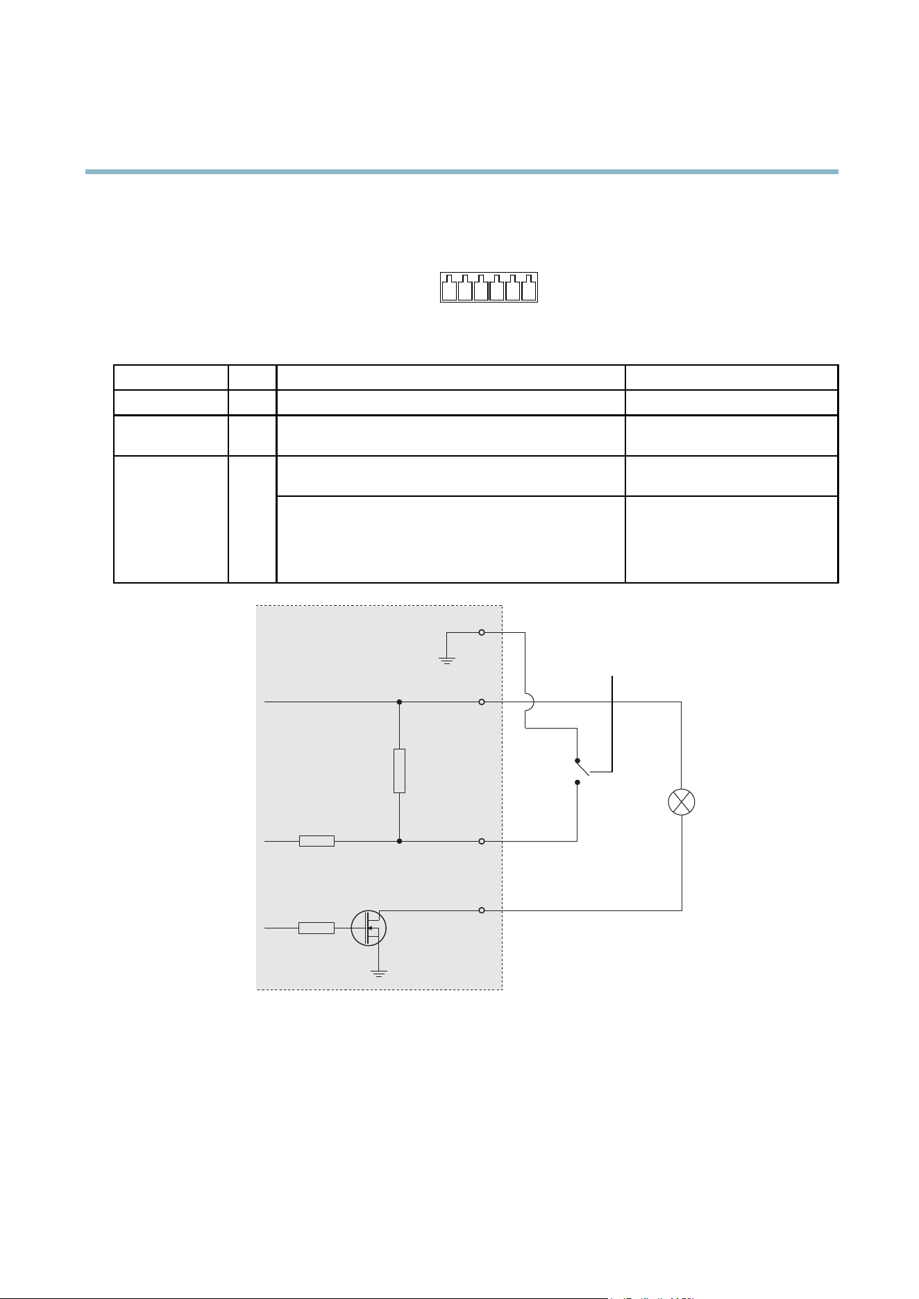
AXIS Q7424–R
Technical Specifications
Connectors
I/O terminal connector
6–pin terminal block for:
• Digital Input
• Digital Output
• Auxiliary power and ground (GND)
1 2 3 4 5 6
Function Pin Notes
Specifications
GND
1
Ground
12V DC Power
2
Can be used to pow er auxiliary equipment.
Note: This pin can only be used as power out.
Max load = 125 m A
Digital input — Connect to GND to activate, or leave floating
(unconnected) to d eactivate.
0to+30VDCConfigurable
(Input or Output)
3–6
Digital output — Internal connection to ground when
activated, floating (unconnected) when deactivated. If
used with an inductive load, e.g. a relay, a diode must be
connected in parallel with the load, for protectio n against
voltage transients.
Max load =100 mA
Max voltage = + 30 V DC
1
2
E.g. push button
3
4
12 V
max. 125mA
D
S
G
55
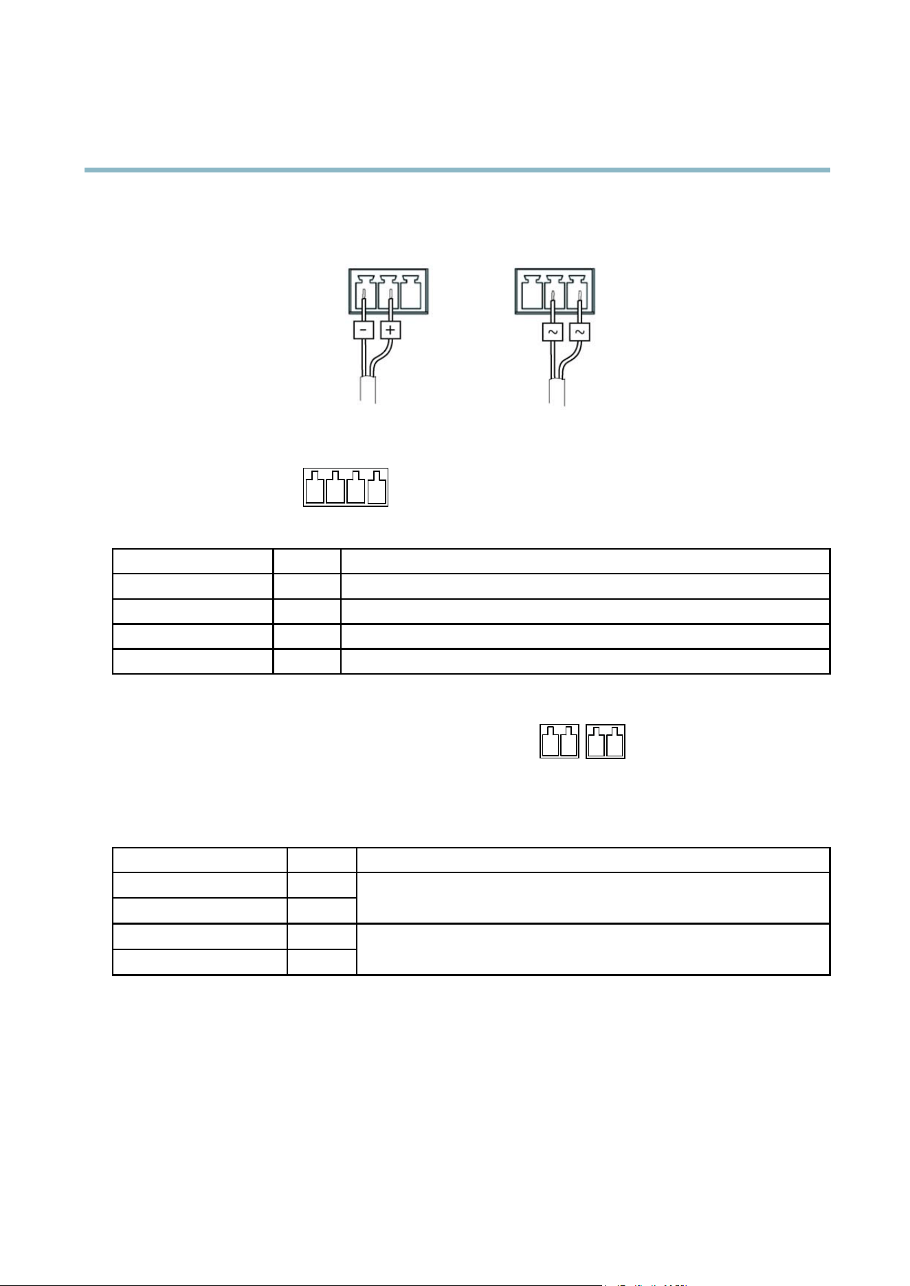
AXIS Q7424–R
Technical Specifications
Power connector
3-pin terminal block for power input.
DC power input
AC power input
Audio connector
4–pin terminal block for:
•Audioinput
• Audio output
1 2 3 4
Function Pin Notes
Microphone/Line in
1
Microphone or line in (mono).
GND
2
Ground.
Line out
3
Line audio out
GND
4
Ground
RS-485/422 connector
Two 2-pin terminal blocks for RS-485/RS-422 serial interface. The serial
port can be configured to suppo rt:
• Two-wire RS-485 half duplex
• Four-wire RS-485 full duplex
• Two-wire RS-422 simplex
• Four-wire RS-422 full duplex point to point communication
RX/TX TX
1 2 3 4
Function Pin Notes
RS-485/RS-422 RX/TX A
1
RS-485/RS-422 RX/TX B
2
(RX) For full duplex RS-485/RS-422
(RX/TX) For half duplex RS-485
RS-485/RS-422 TX A
3
RS-485/RS-422 TX B
4
(TX) For full duplex RS-485/RS-422
Performance C onsiderations
When settings up your system, it is important to consider how various settings and situations will affect performance. Some factors
affect the amount of bandwidth (the bit rate) required, others can affect the frame rate, and some aff ect both. If the load on the
CPU reaches its maxim um, this wi ll also affect the fra m e rate.
The following factors are among the most imp ortant to consider:
• High image resolution and/or lower compression levels result in images containing more data. Bandwidth affected.
56

AXIS Q7424–R
Technical Specifications
• Access by large numbers of Motion JPEG and/or unicast H.264 clients. Bandwidth affected.
• Simultaneous viewing of different streams (resolution, compression) by different clients. Effect on frame rate and bandwidth.
• Accessing Motion JPEG and H.264 video stre ams s imultane ous ly. Frame rate and bandwidth affected.
• Heavy usage of event settings a ffect the product’s CPU load. Frame rate affected.
• Heavy network utilization due to poor infrastructure . Ba ndw idth affected.
• Viewing on poorly performing client computers lowers perceived performance. Frame rate affected.
57

User Manual Ver. M1.11
AXIS Q7424–
R Date: March 2012
© Axis Communications AB, 2012
Part No. 45
412