INSTRUCTIONS FOR:
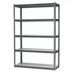
RACKING UNIT WITH 5 SHELVES 600KG
CAPACITY PER
SHELF
MODEL: AP6548
Thank you for purchasing a Sealey product. Manufactured to a high standard this product will, if used according to these instructions and
properly maintained, give you years of trouble free performance.
1. SAFETY INSTRUCTIONS
IMPORTANT: PLEASE READ THESE INSTRUCTIONS CAREFULLY. NOTE THE SAFE OPERATIONAL REQUIREMENTS, WARNINGS & CAUTIONS. USE
THE PRODUCT CORRECTLY AND WITH CARE FOR THE PURPOSE FOR WHICH IT IS INTENDED. FAILURE TO DO SO MAY CAUSE DAMAGE OR
PERSONAL INJURY, AND WILL INVALIDATE THE WARRANTY. PLEASE KEEP INSTRUCTIONS SAFE FOR FUTURE USE.
1.1 GENERAL SAFETY
WARNING! Ensure Health & Safety, and local authority regulations
are adhered to when assembling and using these shelves.
Locate shelves in a suitable area where they will not be an obstruction.
Keep the general area clean, uncluttered and ensure there is
adequate lighting.
WARNING! Erect shelves on a level and solid surface such as
concrete.
Keep children and unauthorised persons away from the storage
area.
DO NOT use the shelves for any purpose other than that for
which they are designed.
DO NOT site the shelves out of doors.
DO NOT get the shelves wet or use in damp or wet locations or
areas where there is condensation.
DO NOT clean the shelf supports with any solvents which may
damage the coated surface.
Ensure that the shelves are properly assembled before loading
them with heavy items.
Maximum load for each shelf is 600kg.
Where possible the unit should be fixed to the wall with
suitable fixings
Place heavier items on the lower shelves.
Where possible heavier items should be evenly distributed across
the shelves.
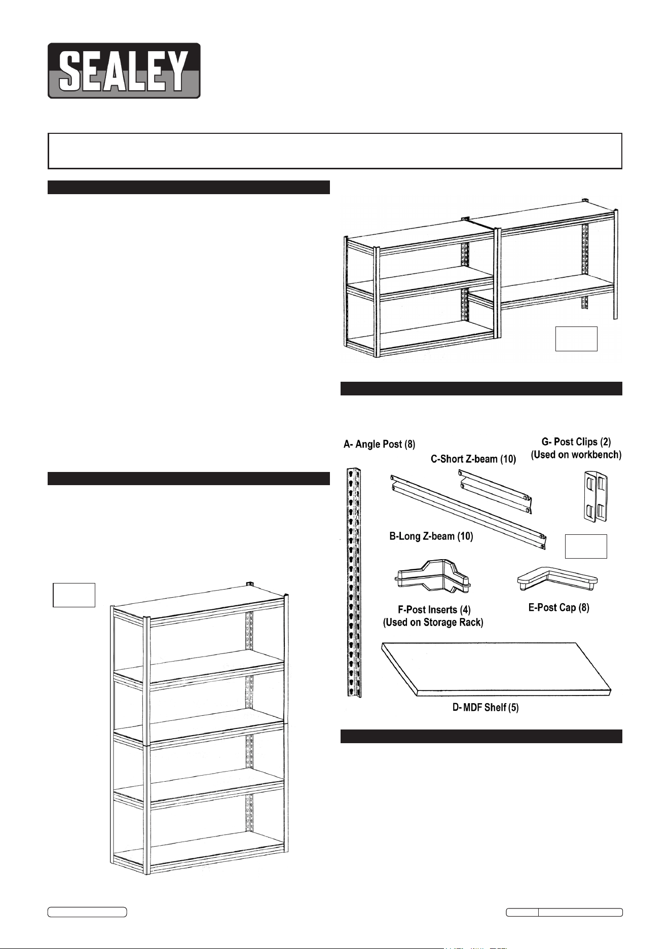
3. CONTENTS
2. INTRODUCTION
Carefully unpack the product and check the contents as detailed
in Fig.3. Should any items be missing or damaged contact your
Sealey stockist.
4. ASSEMBLY
4.1 We recommend that this shelving unit be assembled by two
people. To aid assembly use a rubber mallet or a hammer and a
piece of wood. Do not use a hard faced hammer directly on the
'Z' beams as this will damage their surface finish. Make sure that
all the 'Z' beams are fully interlocked with the angle posts before
using the unit. (The rivets on the 'Z' beams must seat at the
bottom of the keyhole slots ). Do not use any parts that are
damaged and/or distorted as these may assemble incorrectly and
result in an installation that is unsafe and which may cause injury
or damage when the shelves are loaded.
Fig.1
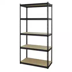
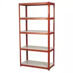
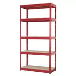
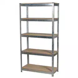
Fully painted steel frame with five MDF shelves. Z Shape beams
offers added strength with 600kg capacity per level, giving a
maximum capacity of 3000kg per rack. Boltless design means no
tools required to assemble. Clips together in minutes. Used as a
single bay full height rack (Fig.1) or split into two separate half
height storage stations (Fig.2).
Height: 1830mm Width: 1215mm Depth: 460mm
Fig.2
Fig.3
AP6548 Issue: 2(SP) - 21/07/16
Original Language Version
© Jack Sealey Limited
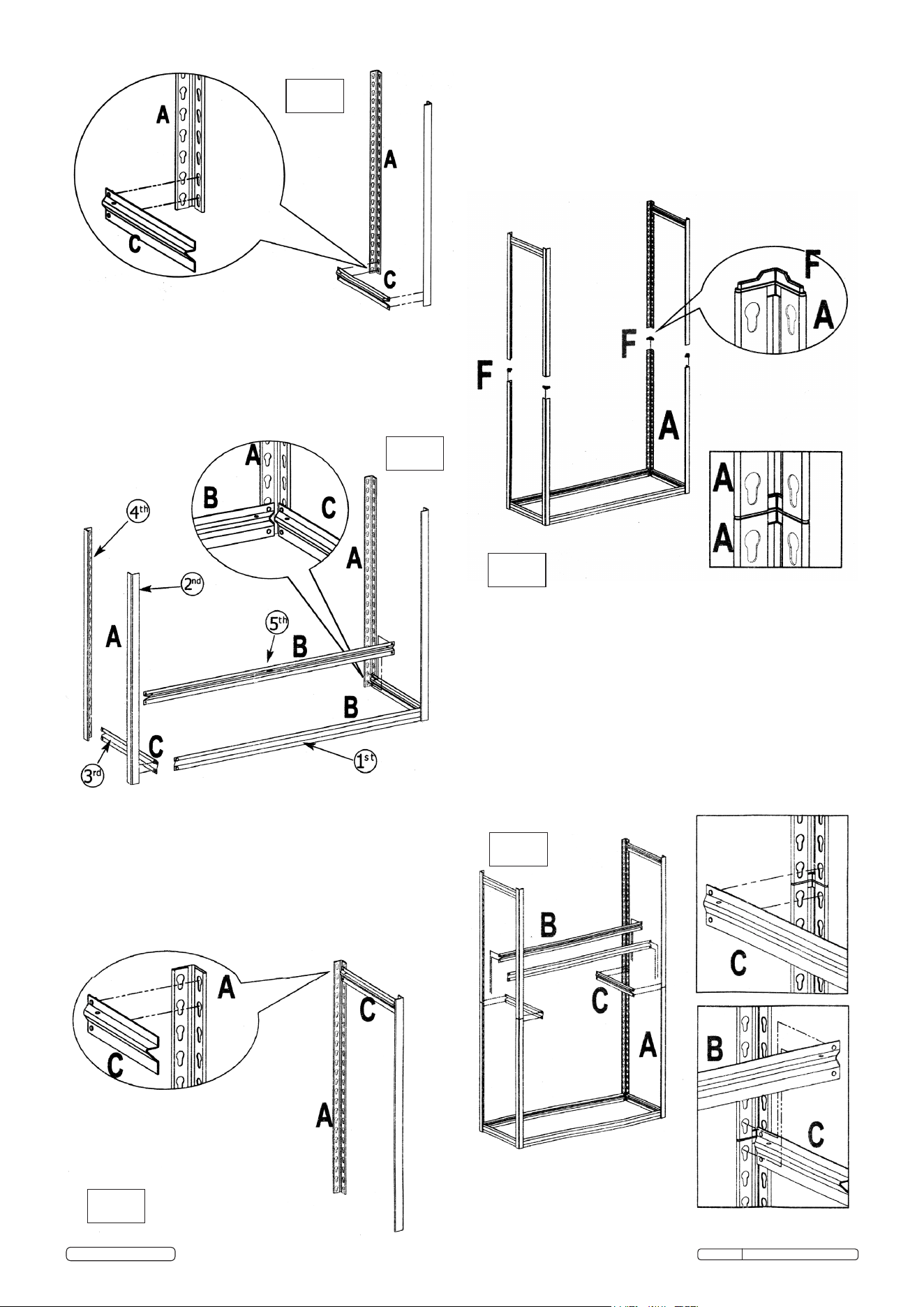
4.2 See Fig.4. Support two upright angle posts (A) in a vertical
position ensuring that the keyhole slots are pointing downwards.
Join them together at the base using a short 'Z' beam (C)
ensuring that the shelf support is facing upwards. Tap the beam
at either end, close to each angle post with a rubber mallet to
ensure that the rivets are seated at the bottom of the keyhole slots.
4.3 See Fig.5. Continue to assemble the complete bottom frame in
the order indicated above in Fig.5 starting with a long 'Z' beam (B).
Ensure that each 'Z' beam is facing upwards. Tap the beam
at either end, close to each angle post with a rubber mallet to
ensure that the rivets are seated at the bottom of the keyhole slots.
4.4 See Fig.6. Now make up an upper end frame by connecting two
angle posts together at the top with a short 'Z' beam (C). Tap the
beam at either end to ensure that the rivets are properly seated
at the bottom of the keyhole slots. Make up a second upper end
frame using the remaining two angle posts and a short 'Z' beam.
4.5 See Fig.7. Take the 4 post inserts (F) and push them into the top
of the four angle posts of the bottom frame assembly. Now join
the two upper end frames to the bottom frame by mounting each
frame onto the post inserts as shown below.
4.6 See Fig.8. Now stabilise the frame assembly by building a shelf
support halfway up the frame that joins together the upper and
lower parts of the frame. As each 'Z' beam is added ensure that
the top rivets are inserted into the bottom keyholes of the upper
frame and the lower rivets are inserted into the top keyholes of
the bottom frame as shown below. Tap the beams at either end
with a rubber mallet to ensure that the rivets are properly seated
into the keyholes.
Fig.5
Fig.4
Fig.7
Fig.8
Fig.6
AP6548 Issue: 2(SP) - 21/07/16
Original Language Version
© Jack Sealey Limited
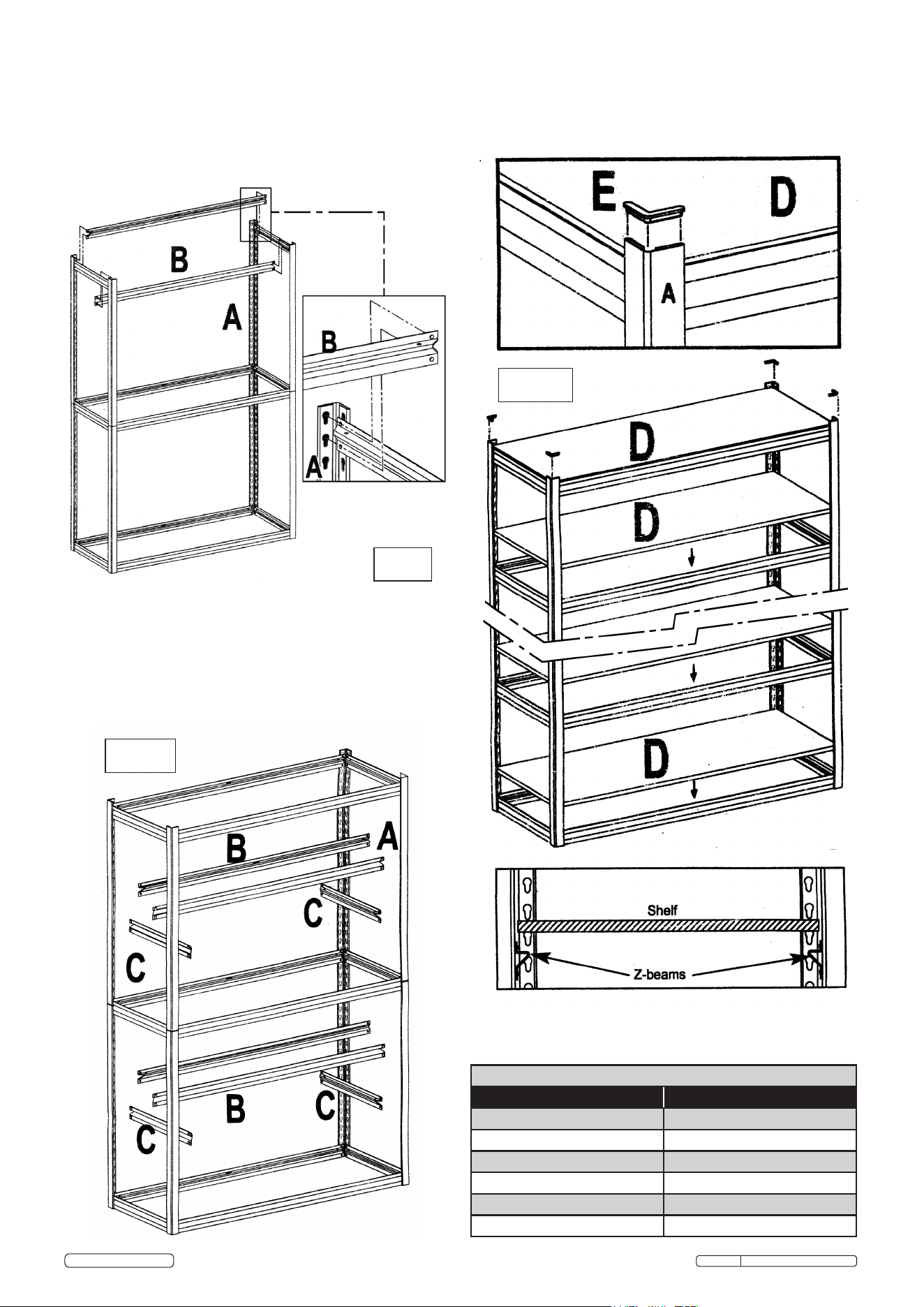
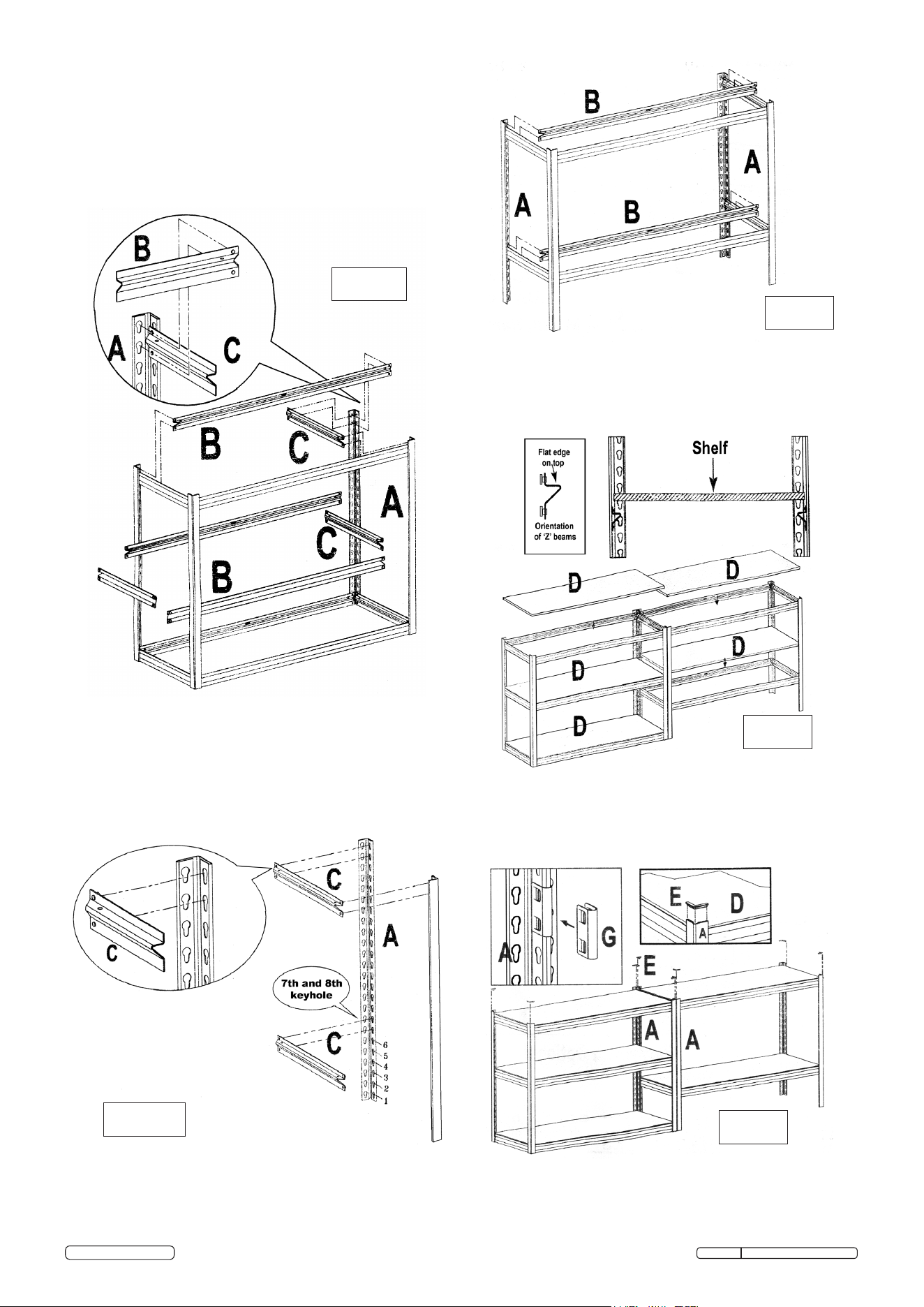
4.9 See Fig.11. Insert a post cap (E) into the top of each angle post
'A' as shown below. Lay a shelf 'D' in between the 'Z' beams at
each level created (See lower detail in Fig.11).
4.8 See Fig.10. Build one shelf support in the top half of the frame
and one shelf support in the bottom half of the frame at the
heights required. (The keyholes allow adjustment in 1 1/2"
increments). Ensure that the beams are the right way up with the
shelf support at the top. Tap the beams at either end with a
rubber mallet to ensure that the rivets are properly seated into
the keyholes.
4.7 See Fig.9. Now stabilise the top part of the frame by adding two
long 'Z' beams (B) to make a shelf support at the top of the
frame as shown in Fig.9. Ensure that the beams are the right
way up with the shelf support at the top. Tap the beams at either
end with a rubber mallet to ensure that the rivets are properly
seated into the keyholes.
Fig.11
Fig.9
Fig.10
SPARE PARTS LISTING FOR AP6548
DESCRIPTION PART NO:
LEG AP6548.01
CROSS BEAM (L=460mm) AP6548.02
CROSS BEAM (L=1215mm) AP6548.02A
SHELF (1215 X 460mm) AP6548.03
CAP AP6548.04
PLASTIC CLIP AP6548.05
AP6548 Issue: 2(SP) - 21/07/16
Original Language Version
© Jack Sealey Limited
4.11 See Fig.13. Now start to build the second low level unit by
making up two end frames as shown in Fig.13. One short 'Z'
beam (C) should be fixed at the top of the angle posts and the
other short 'Z' beam (C) should be fixed at the 7th and 8th
keyholes up from the bottom of the angle posts as shown below.
Ensure that each 'Z' beam is facing upwards. Tap the beam
at either end, close to each angle post with a rubber mallet to
ensure that the rivets are seated at the bottom of the keyhole slots.
4.12 See Fig.14. Join the two end frames together using the four
remaining long 'Z' beams as shown above. Ensure that each 'Z'
beam is facing upwards. Tap the beams at either end, close to
each angle post with a rubber mallet to ensure that the rivets are
seated at the bottom of the keyhole slots.
4.13 See Fig.15. Lay the shelves into position between the 'Z' beams
as shown above.
4.14 See Fig.16. Place the two units end to end as shown below and
join them together using the 2 post clips (G). Insert a post cap
(E) into the top of each 'A' post.
Fig.12
Fig.13
Fig.14
Fig.15
Fig.16
4.10 HALF HEIGHT STORAGE STATION. See Fig.12. Follow steps
4.2 and 4.3 to create a bottom frame with four 'A' posts attached.
Using two long 'Z' beams (B) and two short 'Z' beams (C) build a
shelf support level at the top of the angle posts (A). Tap the
beams at either end, close to each angle post with a rubber
mallet to ensure that the rivets are seated at the bottom of the
keyhole slots. Build another shelf support level at the desired height
within the frame using additional long and short 'Z' beams and
ensure that the rivets are seated at the bottom of the keyhole slots.
AP6548 Issue: 2(SP) - 21/07/16
Original Language Version
© Jack Sealey Limited

AP6548 Issue: 2(SP) - 21/07/16
Original Language Version
© Jack Sealey Limited
NOTE: It is our policy to continually improve products and as such we reserve the right to alter data, specifications and component parts without prior notice.
IMPORTANT: No liability is accepted for incorrect use of this product.
WARRANTY: Guarantee is 12 months from purchase date, proof of which will be required for any claim.
01284 757500
01284 703534
sales@sealey.co.uk
Sole UK Distributor, Sealey Group,
Kempson Way, Suffolk Business Park,
Bury St. Edmunds, Suffolk,
IP32 7AR
www.sealey.co.uk
Environmental Protection
Recycle unwanted materials instead of disposing of them as waste. All tools, accessories and packaging should be
sorted, taken to a recycling centre and disposed of in a manner which is compatible with the environment.
When the product becomes completely unserviceable and requires disposal, drain off any fluids (if applicable)
into approved containers and dispose of the product and the fluids according to local regulations.