
®
271
Programmable 10 MHz DDS Function Generator
Users Manual
January 2005
© 2005 Fluke Corporation, All rights reserved. Printed in USA
All product names are trademarks of their respective companies.
1.888.610.7664 sales@GlobalTestSupply.com
Fluke-Direct.com

271
Users Manual
LIMITED WARRANTY AND LIMITATION OF LIABILITY
Each Fluke product is warranted to be free from defects in material and workmanship under normal use and
service. The warranty period is one year and begins on the date of shipment. Parts, product repairs, and
services are warranted for 90 days. This warranty extends only to the original buyer or end-user customer of
a Fluke authorized reseller, and does not apply to fuses, disposable batteries, or to any product which, in
Fluke's opinion, has been misused, altered, neglected, contaminated, or damaged by accident or abnormal
conditions of operation or handling. Fluke warrants that software will operate substantially in accordance
with its functional specifications for 90 days and that it has been properly recorded on non-defective media.
Fluke does not warrant that software will be error free or operate without interruption.
Fluke authorized resellers shall extend this warranty on new and unused products to end-user customers
only but have no authority to extend a greater or different warranty on behalf of Fluke. Warranty support is
available only if product is purchased through a Fluke authorized sales outlet or Buyer has paid the
applicable international price. Fluke reserves the right to invoice Buyer for importation costs of
repair/replacement parts when product purchased in one country is submitted for repair in another country.
Fluke's warranty obligation is limited, at Fluke's option, to refund of the purchase price, free of charge repair,
or replacement of a defective product which is returned to a Fluke authorized service center within the
warranty period.
To obtain warranty service, contact your nearest Fluke authorized service center to obtain return
authorization information, then send the product to that service center, with a description of the difficulty,
postage and insurance prepaid (FOB Destination). Fluke assumes no risk for damage in transit. Following
warranty repair, the product will be returned to Buyer, transportation prepaid (FOB Destination). If Fluke
determines that failure was caused by neglect, misuse, contamination, alteration, accident, or abnormal
condition of operation or handling, including overvoltage failures caused by use outside the product’s
specified rating, or normal wear and tear of mechanical components, Fluke will provide an estimate of repair
costs and obtain authorization before commencing the work. Following repair, the product will be returned to
the Buyer transportation prepaid and the Buyer will be billed for the repair and return transportation charges
(FOB Shipping Point).
THIS WARRANTY IS BUYER'S SOLE AND EXCLUSIVE REMEDY AND IS IN LIEU OF ALL OTHER
WARRANTIES, EXPRESS OR IMPLIED, INCLUDING BUT NOT LIMITED TO ANY IMPLIED WARRANTY
OF MERCHANTABILITY OR FITNESS FOR A PARTICULAR PURPOSE. FLUKE SHALL NOT BE LIABLE
FOR ANY SPECIAL, INDIRECT, INCIDENTAL, OR CONSEQUENTIAL DAMAGES OR LOSSES,
INCLUDING LOSS OF DATA, ARISING FROM ANY CAUSE OR THEORY.
Since some countries or states do not allow limitation of the term of an implied warranty, or exclusion or
limitation of incidental or consequential damages, the limitations and exclusions of this warranty may not
apply to every buyer. If any provision of this Warranty is held invalid or unenforceable by a court or other
decision-maker of competent jurisdiction, such holding will not affect the validity or enforceability of any other
provision.
Fluke Corporation
P.O. Box 9090
Everett, WA 98206-9090
U.S.A.
Fluke Europe B.V.
P.O. Box 1186
5602 BD Eindhoven
The Netherlands
11/99
To register your product online, visit register.fluke.com
1.888.610.7664 sales@GlobalTestSupply.com
Fluke-Direct.com

Safety
This function generator is a Safety Class I instrument according to IEC classification and
has been designed to meet the requirements of EN61010-1 (Safety Requirements for
Electrical Equipment for Measurement, Control and Laboratory Use). It is an Installation
Category II instrument intended for operation from a normal single phase supply.
This instrument has been tested in accordance with EN61010-1 and has been supplied in
a safe condition. This instruction manual contains some information and warnings which
have to be followed by the user to ensure safe operation and to retain the instrument in a
safe condition.
This instrument has been designed for indoor use in a Pollution Degree 2 environment in
the temperature range 5 °C to 40 °C, 20 % - 80 % RH (non-condensing). It may
occasionally be subjected to temperatures between +5 °C and -10 °C without degradation
of its safety. Do not operate the instrument while condensation is present.
Use of this instrument in a manner not specified by these instructions may impair the
safety protection provided. Do not operate the instrument outside its rated supply
voltages or environmental range.
Warning
To avoid the possibility of electric shock:
• This instrument must be earthed.
• Any interruption of the mains earth conductor inside or
outside the instrument will make the instrument
dangerous. Intentional interruption is prohibited. The
protective action must not be negated by the use of an
extension cord without a protective conductor.
• When the instrument is connected to its supply, terminals
may be live and opening the covers or removal of parts
(except those to which access can be gained by hand) is
likely to expose live parts.
• The apparatus shall be disconnected from all voltage
sources before it is opened for any adjustment,
replacement, maintenance or repair.
• Any adjustment, maintenance and repair of the opened
instrument under voltage shall be avoided as far as
possible and, if inevitable, shall be carried out only by a
skilled person who is aware of the hazard involved.
• Make sure that only fuses with the required rated current
and of the specified type are used for replacement. The use
of makeshift fuses and the short-circuiting of fuse holders
is prohibited.
Caution
If the instrument is clearly defective, has been subject to
mechanical damage, excessive moisture or chemical corrosion
the safety protection may be impaired and the apparatus should
be withdrawn from use and returned for checking and repair.
i
1.888.610.7664 sales@GlobalTestSupply.com
Fluke-Direct.com
271
Users Manual
ii
Note
This instrument uses a Lithium button cell for non-volatile memory battery
back-up. Typical battery life is 5 years. In the event of replacement
becoming necessary, replace only with a cell of the correct type, a 3 V
Li/Mn0
2
20 mm button cell type 2032. Do not mix with solid waste stream.
Do not cut open, incinerate, expose to temperatures above 60 °C or attempt
to recharge. Used batteries should be disposed of by a qualified recycler or
hazardous materials handler. Contact your authorized Fluke Service
Center for recycling information.
Caution
Do not wet the instrument when cleaning it and in particular use
only a soft dry cloth to clean the LCD window.
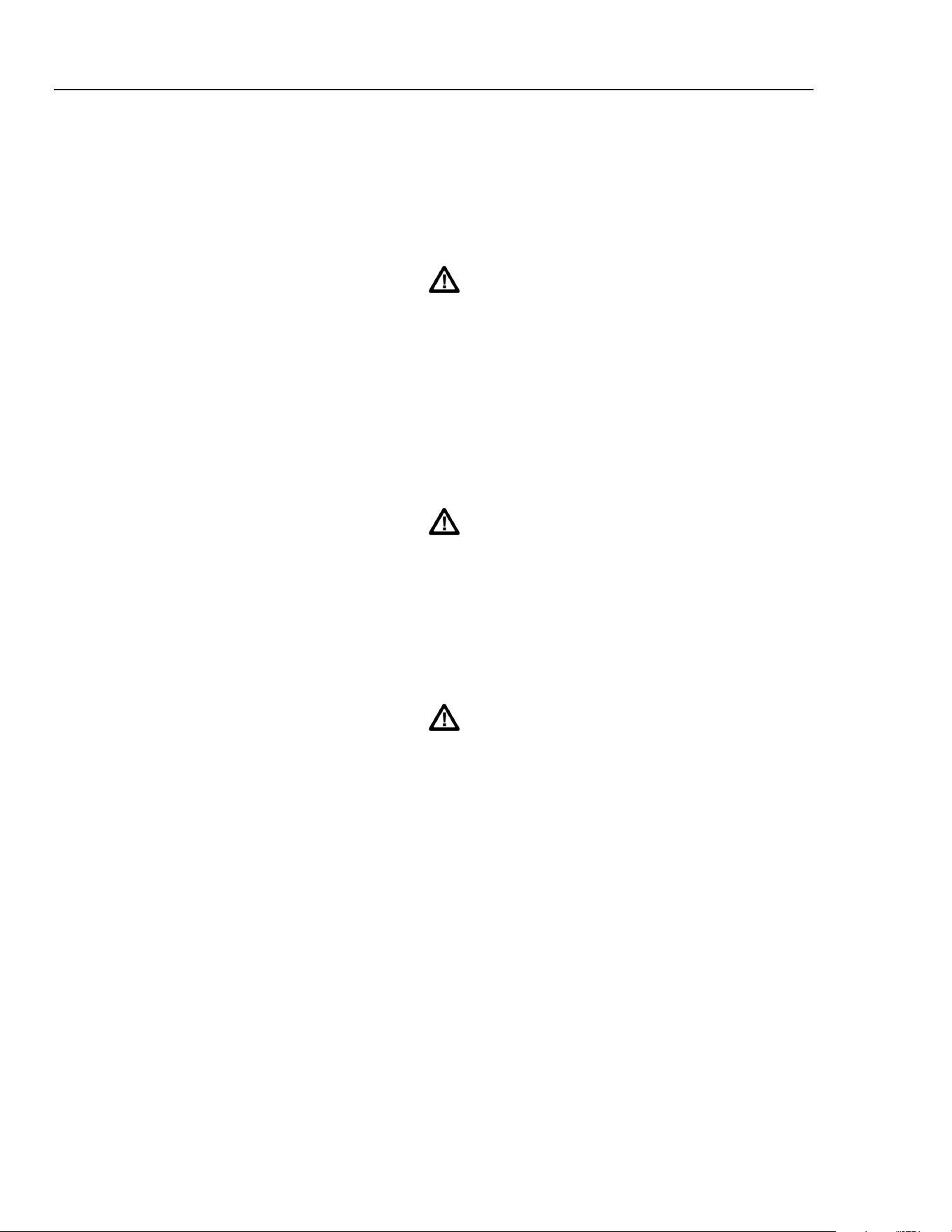
The following symbols are used on the instrument and in this manual:
Caution - refer to the accompanying documentation,
incorrect operation may damage the instrument.
Terminal connected to chassis ground.
Mains supply OFF.
Mains supply ON.
Alternating current.
Warning - hazardous voltages may be present.
1.888.610.7664 sales@GlobalTestSupply.com
Fluke-Direct.com

EMC Compliance
This instrument meets the requirements of the EMC Directive 89/336/EEC.
Compliance was demonstrated by meeting the test limits of the following standards:
Emissions
EN61326 (1998) EMC product standard for Electrical Equipment for Measurement,
Control and Laboratory Use. Test limits used were:
a) Radiated: Class B
b) Conducted: Class B
c) Harmonics:
EN61000-3-2 (2000) Class A
The instrument is Class A by product category.
Immunity
EN61326 (1998) EMC product standard for Electrical Equipment for Measurement,
Control and Laboratory Use. Test methods, limits and performance achieved were:
a) EN61000-4-2 (1995)
Electrostatic Discharge: 4 kV air, 4 kV contact
Performance A.
b) EN61000-4-3 (1997)
Electromagnetic Field: 3 V/m, 80 % AM at 1 kHz
Performance A.
c) EN61000-4-11 (1994)
Voltage Interrupt: 1 cycle, 100 %
Performance A.
d) EN61000-4-4 (1995)
Fast Transient: 1 kV peak (ac line), 0.5 kV peak (signal lines
and RS232/GPIB ports)
Performance A.
e) EN61000-4-5 (1995)
Surge: 0.5 kV (line to line), 1 kV (line to ground)
Performance A.
f) EN61000-4-6 (1996)
Conducted RF: 3 V, 80 % AM at 1kHz (ac line only; signal
connections <3 m not tested)
Performance A.
According to EN61326 the definitions of performance criteria are:
Performance criterion A: ‘During test normal performance within the specification
limits.’
Performance criterion B: ‘During test, temporary degradation, or loss of function or
performance which is self-recovering’.
Performance criterion C: ‘During test, temporary degradation, or loss of function or
performance which requires operator intervention or system
reset occurs.’
Cautions
To ensure continued compliance with the EMC directive the
following precautions should be observed:
a) connect the generator to other equipment using only high
quality, double-screened cables.
iii
1.888.610.7664 sales@GlobalTestSupply.com
Fluke-Direct.com

271
Users Manual
iv
b) after opening the case for any reason ensure that all signal
and ground connections are remade correctly before replacing
the cover. Always ensure all case screws are correctly refitted
and tightened.
c) In the event of part replacement becoming necessary, only
use components of an identical type. Refer to the Service
Manual.
1.888.610.7664 sales@GlobalTestSupply.com
Fluke-Direct.com

v
Table of Contents
Chapter Title Page
Introduction and Specifications .................................................................... 1-1
Introduction........................................................................................................ 1-2
Principal features........................................................................................... 1-2
Specifications..................................................................................................... 1-4
Waveforms .................................................................................................... 1-4
Sine............................................................................................................ 1-4
Square........................................................................................................ 1-4
Triangle..................................................................................................... 1-4
Positive and Negative Ramps.................................................................... 1-4
Positive and Negative Pulses .................................................................... 1-5
Multi-level Square Wave .......................................................................... 1-5
Arbitrary.................................................................................................... 1-5
Hop............................................................................................................ 1-5
Noise ......................................................................................................... 1-5
Modulation Modes......................................................................................... 1-5
Continuous ................................................................................................ 1-5
Trigger and burst....................................................................................... 1-6
Gated......................................................................................................... 1-6
Sweep........................................................................................................ 1-6
Amplitude Modulation.............................................................................. 1-6
Frequency Shift Keying (FSK) ................................................................. 1-6
Start/Stop Phase ........................................................................................ 1-7
Trigger Generator...................................................................................... 1-7
Outputs .......................................................................................................... 1-7
Main Output.............................................................................................. 1-7
Aux Out..................................................................................................... 1-7
Trig/Sweep Out......................................................................................... 1-7
Inputs............................................................................................................. 1-8
Ext Trig..................................................................................................... 1-8
VCA In...................................................................................................... 1-8
Phase locking................................................................................................. 1-8
Clock In/Out.............................................................................................. 1-8
Sync Out.................................................................................................... 1-8
Interfaces ....................................................................................................... 1-8
1.888.610.7664 sales@GlobalTestSupply.com
Fluke-Direct.com

271
Users Manual
vi
General .......................................................................................................... 1-8
2 Installation ........................................................................................... 2-1
Mains Operating Voltage................................................................................... 2-2
Fuse.................................................................................................................... 2-2
Mains Lead ........................................................................................................ 2-2
Mounting............................................................................................................ 2-2
3 Connections......................................................................................... 3-1
Front Panel Connections.................................................................................... 3-2
MAIN OUT................................................................................................... 3-2
AUX OUT..................................................................................................... 3-2
EXT TRIG..................................................................................................... 3-2
Rear Panel Connections..................................................................................... 3-2
CLOCK IN/OUT........................................................................................... 3-2
VCA IN ......................................................................................................... 3-3
SYNC OUT................................................................................................... 3-3
TRIG/SWEEP OUT ...................................................................................... 3-3
RS232............................................................................................................ 3-4
GPIB (IEEE-488) .......................................................................................... 3-4
4 General Operation............................................................................... 4-1
Introduction........................................................................................................ 4-2
DDS Principles .................................................................................................. 4-2
Switching On ..................................................................................................... 4-2
Display Contrast............................................................................................ 4-3
Keyboard ....................................................................................................... 4-3
Principles of Editing .......................................................................................... 4-4
5 Main Generator Operation.................................................................. 5-1
Introduction........................................................................................................ 5-2
Main Generator Parameters ............................................................................... 5-2
Frequency...................................................................................................... 5-2
Output Level.................................................................................................. 5-3
Output Impedance ......................................................................................... 5-4
DC Offset ...................................................................................................... 5-4
DC Output ..................................................................................................... 5-5
Symmetry ...................................................................................................... 5-5
Warning and Error Messages............................................................................. 5-6
The Auxiliary Output......................................................................................... 5-7
Auxiliary Output Phase ................................................................................. 5-8
Waveform Generation Options.......................................................................... 5-9
Square Wave Generation............................................................................... 5-9
Filter .............................................................................................................. 5-9
Auxiliary Output............................................................................................ 5-10
Frequency Stop.............................................................................................. 5-10
Trigger/Sweep Output................................................................................... 5-10
6 Sweep Operation................................................................................. 6-1
Introduction........................................................................................................ 6-2
Connections for Sweep Operation..................................................................... 6-2
Setting Sweep Span and Markers ...................................................................... 6-2
1.888.610.7664 sales@GlobalTestSupply.com
Fluke-Direct.com

Contents (continued)
Setting Sweep Mode, Ramp Time and Source .................................................. 6-3
Frequency Stepping Resolution......................................................................... 6-4
7 Triggered Burst and Gate................................................................... 7-1
Introduction........................................................................................................ 7-2
Internal Trigger Generator............................................................................. 7-2
External Trigger Input................................................................................... 7-2
Triggered Burst.................................................................................................. 7-2
Trigger Source............................................................................................... 7-3
Burst Count.................................................................................................... 7-3
Start/Stop Phase............................................................................................. 7-3
Gated Mode........................................................................................................ 7-4
Gate Source ................................................................................................... 7-4
8 Amplitude Modulation......................................................................... 8-1
Introduction........................................................................................................ 8-2
Amplitude Modulation (Internal)....................................................................... 8-2
Modulation Frequency................................................................................... 8-2
Modulation Depth.......................................................................................... 8-2
Modulation Waveform .................................................................................. 8-3
VCA (External).................................................................................................. 8-3
9 FSK ....................................................................................................... 9-1
Introduction........................................................................................................ 9-2
Frequency Setting.......................................................................................... 9-2
Trigger Source............................................................................................... 9-2
10 Special Waveforms ............................................................................. 10-1
Staircase............................................................................................................. 10-2
Arbitrary............................................................................................................. 10-3
Recalling Arbitrary Waveforms .................................................................... 10-3
Storing Arbitrary Waveforms........................................................................ 10-3
Noise.................................................................................................................. 10-4
11 Hop ....................................................................................................... 11-1
Introduction........................................................................................................ 11-2
Setting each Waveform Step.............................................................................. 11-2
Defining the Sequence and Timing.................................................................... 11-2
Running the Sequence ....................................................................................... 11-3
Timing Considerations....................................................................................... 11-3
Saving Hop Settings........................................................................................... 11-4
12 System Operations.............................................................................. 12-1
Storing and Recalling Set-Ups........................................................................... 12-1
System Settings.................................................................................................. 12-2
Cursor Style................................................................................................... 12-2
Rotary Control............................................................................................... 12-2
Power Up Setting........................................................................................... 12-2
CLOCK IN/OUT Setting............................................................................... 12-2
13 Synchronizing Generators.................................................................. 13-1
vii
1.888.610.7664 sales@GlobalTestSupply.com
Fluke-Direct.com

271
Users Manual
viii
Introduction........................................................................................................ 13-2
Synchronizing Principles................................................................................... 13-2
Connections for Synchronization....................................................................... 13-2
Generator Set-Ups.............................................................................................. 13-2
Synchronizing.................................................................................................... 13-3
14 Calibration............................................................................................ 14-1
Introduction........................................................................................................ 14-2
Equipment Required.......................................................................................... 14-2
Calibration Procedure ........................................................................................ 14-2
Setting the Password...................................................................................... 14-2
Using the Password to Access Calibration or Change the Password ............ 14-3
Calibration Routine ....................................................................................... 14-3
15 Application Examples......................................................................... 15-1
Introduction........................................................................................................ 15-2
Default Settings.................................................................................................. 15-2
Simple Main Generator Operation..................................................................... 15-2
Pulse Trains........................................................................................................ 15-2
Low Duty Cycle Pulse Trains............................................................................ 15-3
Multiple Pulses .................................................................................................. 15-4
Variable Transition Pulse Waveforms............................................................... 15-4
Slew-Limited Transitions.............................................................................. 15-4
Band-Limited Pulses ..................................................................................... 15-5
Pulses With Overshoot.................................................................................. 15-5
16 Remote Operation ............................................................................... 16-1
Remote Operation.............................................................................................. 16-2
Address and Baud Rate Selection.................................................................. 16-2
Remote/Local Operation ............................................................................... 16-2
RS232 Interface............................................................................................. 16-3
Single Instrument RS232 Connections ..................................................... 16-3
Addressable RS232 Connections.............................................................. 16-3
RS232 Character Set................................................................................. 16-4
Addressable RS232 Interface Control Codes............................................ 16-4
Full List of Addressable RS232 Interface Control Codes......................... 16-6
GPIB Interface............................................................................................... 16-6
GPIB Subsets ............................................................................................ 16-6
GPIB IEEE Std. 488.2 Error Handling ..................................................... 16-6
GPIB Parallel Poll..................................................................................... 16-7
Status Reporting........................................................................................ 16-7
Standard Event Status and Standard Event Status Enable Registers......... 16-8
Status Byte Register and Service Request Enable Register ...................... 16-8
Status Model.................................................................................................. 16-9
Power on Settings...................................................................................... 16-9
Remote Commands............................................................................................ 16-10
RS232 Remote Command Formats............................................................... 16-10
GPIB Remote Command Formats................................................................. 16-10
Command List............................................................................................... 16-11
Function Selection......................................................................................... 16-12
Main Generator Parameters........................................................................... 16-12
Sweep Parameters.......................................................................................... 16-12
Trigger and Gate............................................................................................ 16-13
1.888.610.7664 sales@GlobalTestSupply.com
Fluke-Direct.com

Contents (continued)
AM Parameters.............................................................................................. 16-13
FSK Parameters............................................................................................. 16-13
Staircase and Arbitrary Waveforms .............................................................. 16-14
Waveform Generation Options...................................................................... 16-14
Hop Commands............................................................................................. 16-14
System Commands........................................................................................ 16-15
Status Commands.......................................................................................... 16-15
Miscellaneous Commands............................................................................. 16-16
Phase Locking Commands ............................................................................ 16-16
Remote Command Summary............................................................................. 16-17
Appendices
A AC Supply Voltage Settings........................................................................ A-1
B DDS Operation and Further Waveform Considerations ............................. B-1
C Application Information Notes.................................................................... C-1
D Warning and Error Messages ...................................................................... D-1
E Factory System Defaults ............................................................................. E-1
F Waveform Manager Plus............................................................................. F-1
G Front and Rear Panels.................................................................................. G-1
ix
1.888.610.7664 sales@GlobalTestSupply.com
Fluke-Direct.com

271
Users Manual
x
1.888.610.7664 sales@GlobalTestSupply.com
Fluke-Direct.com

1-1
Chapter 1
Introduction and Specifications
Title Page
Introduction........................................................................................................ 1-2
Principal features ........................................................................................... 1-2
Specifications..................................................................................................... 1-4
Waveforms .................................................................................................... 1-4
Sine............................................................................................................ 1-4
Square........................................................................................................ 1-4
Triangle ..................................................................................................... 1-4
Positive and Negative Ramps.................................................................... 1-4
Positive and Negative Pulses .................................................................... 1-5
Multi-level Square Wave .......................................................................... 1-5
Arbitrary.................................................................................................... 1-5
Hop............................................................................................................ 1-5
Noise ......................................................................................................... 1-5
Modulation Modes......................................................................................... 1-5
Continuous ................................................................................................ 1-5
Trigger and burst ....................................................................................... 1-6
Gated ......................................................................................................... 1-6
Sweep ........................................................................................................ 1-6
Amplitude Modulation.............................................................................. 1-6
Frequency Shift Keying (FSK) ................................................................. 1-6
Start/Stop Phase ........................................................................................ 1-7
Trigger Generator...................................................................................... 1-7
Outputs .......................................................................................................... 1-7
Main Output .............................................................................................. 1-7
Aux Out..................................................................................................... 1-7
Trig/Sweep Out ......................................................................................... 1-7
Inputs ............................................................................................................. 1-8
Ext Trig ..................................................................................................... 1-8
VCA In...................................................................................................... 1-8
Phase locking................................................................................................. 1-8
Clock In/Out.............................................................................................. 1-8
Sync Out.................................................................................................... 1-8
Interfaces ....................................................................................................... 1-8
General .......................................................................................................... 1-8
1.888.610.7664 sales@GlobalTestSupply.com
Fluke-Direct.com

271
Users Manual
1-2
Introduction
This Programmable Function Generator uses direct digital synthesis to provide high
performance and extensive facilities at a breakthrough price. It can generate a variety of
waveforms between 0.1 mHz and 10 MHz with a resolution of 7 digits and an accuracy
better than 10 ppm.
Principal features
Direct digital synthesis for accuracy & stability
Direct digital synthesis (DDS) is a technique for generating waveforms digitally using a
phase accumulator, a look-up table and a DAC. The accuracy and stability of the
resulting waveforms are related to that of the crystal master clock.
In addition the DDS generator offers high spectral purity, low phase noise and excellent
frequency agility.
A wide range of waveforms
High quality sine, square and pulse waveforms can be generated over the full frequency
range of 0.1 mHz to 10 MHz.
Triangle ramp and multi-level square waveforms also be generated over limited
frequency ranges.
Variable symmetry or duty-cycle is available for all standard waveforms.
Arbitrary waveform capability
Arbitrary waveforms can be loaded via the digital interfaces and then used in a similar
way to the standard waveforms.
Up to five arbitrary waveforms of 1024 10-bit words can be stored in non-volatile
memory. The maximum waveform clock frequency is 27.48 MHz.
This facility considerably expands the versatility of the instrument, making it suitable for
the generation of highly complex waveform patterns.
In addition, numerous complex waveforms are pre-defined in ROM, including commonly
used wave shapes such as sin(x)/x, exponentially decaying sine wave, etc. Further wave
shapes will be added to the library in response to customer requests.
Sweep
All waveforms can be swept over their full frequency range at a rate variable between
10 milliseconds and 15 minutes. Sweeps are fully phase continuous.
Sweeps can be linear or logarithmic, single or continuous. Single sweeps can be triggered
from the front panel, the trigger input or the digital interfaces. Two sweep markers are
provided.
Amplitude modulation
AM is available for all waveforms and is variable in 1 % steps up to 100 %. An internal
AM source is incorporated. Modulation may also be controlled by an external generator.
Frequency shift keying
FSK provides phase coherent switching between two selected frequencies at a rate
defined by the switching signal source.
1.888.610.7664 sales@GlobalTestSupply.com
Fluke-Direct.com

Introduction and Specifications
Introduction 1
1-3
The rate can be set from dc to 50 kHz internally, or dc to 1 MHz externally.
Triggered burst and gated modes
All waveforms are available as a triggered burst whereby each positive edge of the trigger
signal will produce one burst of the carrier, starting and stopping at the phase angle
specified by the start-stop phase setting.
The number of cycles in the burst can be set between 0.5 and 1023. The gated mode turns
the output signal on when the gating signal is high and off when it is low.
Both triggered and gated modes can be operated from the internal trigger generator
(0.005 Hz to 50 kHz) or from an external source (dc to 1 MHz).
Waveform hop and noise
The generator can be set up to hop between a number of different waveform settings,
either at a predetermined rate or in response to a manual trigger.
Up to 16 different hop waveforms can be defined in terms of frequency, amplitude,
function, offset and duration. Duration is variable in 1 ms steps up to 60 s. The generator
can also be set to simulate random noise within the bandwidth 0.03 Hz to 700 kHz with
adjustable amplitude and offset.
Multiple phase-locked generators
The signals from the reap panel
CLOCK IN/OUT socket and SYNC OUT sockets can
be used to phase lock two or more generators.
Phase locked generators can be used to generate multi-phase waveforms or locked
waveforms of different frequencies.
Easy and convenient to use
All of the main generator parameters are clearly displayed together on a backlit liquid
crystal display (LCD) with 4 rows of 20 characters. Sub-menus are used for the
modulation modes and other complex functions.
All parameters can be entered directly from the numeric keypad. Alternatively most
parameters can be incremented or decremented using the rotary encoder.
This system combines quick and easy numeric data entry with quasi-analogue adjustment
when required.
Fully programmable via addressable RS232 and GPIB interfaces
The generator has RS-232 and GPIB (IEEE-488) interfaces which can be used for remote
control of all of the instrument functions and for downloading arbitrary waveforms.
As well as operating in conventional RS-232 mode the serial interface can be used in
addressable mode whereby up to 32 instruments can be linked to a single PC serial port.
1.888.610.7664 sales@GlobalTestSupply.com
Fluke-Direct.com

271
Users Manual
1-4
Specifications
Specifications apply at 18- 28 °C after one hour warm-up, at maximum output into 50 Ω.
Waveforms
Standard waveforms include sine, square, triangle, dc, positive ramp, negative ramp,
positive pulse, negative pulse and multi-level square wave. In addition the instrument
provides arbitrary waveforms (arb) and pseudo-random noise.
Sine
Range: 0·1 mHz to 10 MHz
Resolution: 0·1 mHz or 7 digits
Symmetry control: 1 to 99 % (0.1 % resolution) from 0.1 mHz to 10 MHz.
Accuracy: 10 ppm for 1 year
Temperature stability: Typically <1 ppm/ºC outside 18 to 28 °C
Output Level:
2.5 mV to 10 V p−p into 50 Ω
Harmonic distortion: <0.3 % THD to 100 kHz;
<–50 dBc to 300 kHz
<–35dBc to 10 MHz
Non−harmonic spurious:
<–65 dBc to 1 MHz,
<–65 dBc +6 dB/octave 1 MHz to 10 MHz
Square
Range: 0.1 mHz to 10 MHz
Resolution: 0.1 mHz or 7 digits
Symmetry control: 1 to 99 % (0.1 % resolution) from 0.1 mHz to 30 kHz
20 % to 80 % (0.1 % resolution) from 30 kHz to 10 MHz
Accuracy: 10 ppm for 1 year
Output level:
2.5 mV to 10 V p−p into 50 Ω
Rise and fall times: <22 ns
Aberrations: <5 % +2 mV
Triangle
Range: 0.1 mHz to 100 kHz
Resolution: 0.1 mHz or 7 digits
Symmetry control: 1 to 99 % (0.1 % resolution) from 0.1 mHz to 100 kHz
Accuracy: 10 ppm for 1 year
Output level:
2.5 mV to 10 V p−p into 50 Ω
Linearity error: <0.5 % to 30 kHz
Positive and Negative Ramps
Range: 0.1 mHz to 100 kHz
Resolution: 0.1 mHz (7 digits)
Symmetry Control: 1 to 99 % (0.1 % resolution) from 0.1 mHz to 100 kHz
Accuracy: 10 ppm for 1 year
Output Level:
2.5 mV to 10 V p−p into 50 Ω
Linearity Error: <0.5 % to 30 kHz
1.888.610.7664 sales@GlobalTestSupply.com
Fluke-Direct.com

Introduction and Specifications
Specifications 1
1-5
Positive and Negative Pulses
Range: 0.1 mHz to 10 MHz
Resolution: 0.1 mHz or 7 digits
Symmetry control: 1 to 99 % (0.1 % resolution) from 0.1 mHz to 30 kHz
20 to 80 % (0.1 % resolution) from 30 kHz to 10 MHz
Accuracy: 10 ppm for 1 year
Output level: 2.5 mV to 10 V p-p into 50 Ω
Rise and fall times: <22 ns
Aberrations: <5 % +2 mV
Multi-level Square Wave
Maximum of 16 steps of discrete amplitude (10 bit resolution) and duration (1 to 1024
samples). Allows generation of three-level square wave, staircase, multiplexed LCD
driver signals, etc.
Range: All waveform points are continuously output up to
approximately 27 kHz, above which sampling will introduce
an uncertainty of 1 clock edge (1 clock = 36 ns).
Output level: 5 mV to 20 V p-p into an open circuit.
Rise and fall times: <22 ns
Arbitrary
A number of frequently required waveforms are pre-programmed in the internal read-
only memory (ROM). Waveforms may also be downloaded via the RS232 or GPIB
interfaces and stored in the internal non-volatile random-access memory (RAM).
Frequency range: 0.1 mHz to 10 MHz
Waveform points are continuously output up to
approximately 27 kHz, above which they are sampled.
Output level: 5 mV to 20 V p-p into an open circuit.
Sampling frequency: 27.48 MHz
Number of samples: 1024
Sample levels: 1024 (10 bits)
Hop
Up to 16 different waveforms can be output in sequence at a rate determined by either the
internal timer, an external trigger a remote command, or from the keyboard. Each
waveform can be set to any wave shape (except noise), frequency, amplitude and offset.
Frequency-only changes are phase-continuous.
Noise
White noise output with a typical -3 dB bandwidth of 0.03 Hz to 700 kHz. Amplitude and
offset are adjustable. Noise can only be used with gated and AM modes.
Modulation Modes
Continuous
Continuous cycles of the selected waveform are output at the programmed frequency.
1.888.610.7664 sales@GlobalTestSupply.com
Fluke-Direct.com

271
Users Manual
1-6
Trigger and burst
Phase-coherent signal keying: each positive edge of the trigger signal will produce one
burst of the carrier, starting and stopping at the phase angle specified by the start/stop
phase setting.
Carrier frequency: 0.1 mHz to >1 MHz
Carrier waveforms: All
Number of cycles: 1 to 1023 (resolution 1 cycle)
or 0.5 to 511.5 (resolution 0.5 cycle).
Trigger repetition rate: dc to 50 kHz internal, dc to 1 MHz external.
Source: Manual (front panel key), internal trigger generator, external
signal or remote interface.
Gated
Non-phase coherent signal keying: the output carrier wave is on while the gate signal is
high and off while it is low.
Carrier frequency: From 0.1 mHz to 10 MHz.
Carrier waveforms: All
Trigger repetition rate: dc to 50 kHz internal, dc to 1 MHz external.
Gate signal source: Manual (front panel key), internal trigger generator, external
signal or remote interface.
Sweep
Carrier waveforms: All
Sweep modes: Linear or logarithmic, single or continuous.
Sweep width: From 0.1 mHz to 10 MHz in one range. Phase continuous.
Start and stop frequency may be set independently.
Sweep time: 10 ms to 999 s with 3 digit resolution.
Markers: Two, variable during sweep, available at the rear panel
socket.
Sweep trigger source: The sweep may be free run or triggered manually (front
panel key), by an external signal or through a remote
interface.
Amplitude Modulation
Carrier frequency: From 0.1 mHz to 10 MHz.
Carrier waveforms: All.
Depth: Variable 0 to 100% typical, resolution 1 %.
Internal source: 1 kHz fixed sine wave or 0.005 Hz to 50 kHz square wave.
External: See VCA In below.
Frequency Shift Keying (FSK)
Phase coherent switching between two selected frequencies at a rate defined by the
switching signal source.
Carrier frequency: From 0.1 mHz to 10 MHz.
Carrier waveforms: All.
Switch repetition rate: dc to 50 kHz internal, dc to 1 MHz external.
Switching signal source: Manual (front panel key), internal trigger generator, external
signal or remote interface.
1.888.610.7664 sales@GlobalTestSupply.com
Fluke-Direct.com

Introduction and Specifications
Specifications 1
1-7
Start/Stop Phase
The phase relationship between the
MAIN OUT and AUX OUT sockets is determined by
the start/stop phase setting.
Carrier frequency: 0.1 mHz to >1 MHz.
Carrier waveforms: All.
Range: -360 to +360 degrees.
Resolution: 1 degree.
Accuracy: Typically 1 degree to 30 kHz.
Trigger Generator
Internal source 0.005 Hz to 50 kHz square wave, adjustable in 20 µs steps with 3 digit
resolution. Available for external use from a rear panel socket.
Outputs
Main Output
Output Impedance: 50 Ω or 600 Ω
Amplitude: 5 mV to 20 V p-p into an open circuit,
2.5 mV to 10V p-p into 50 Ω/600 Ω.
Output can be specified as VhiZ (open circuit value) or V
(voltage into characteristic impedance) in p-p, r.m.s. or dBm.
Amplitude accuracy: ±3 % ±1 mV at 1 kHz into 50 Ω/600 Ω.
Amplitude flatness: ±0.2 dB to 500 kHz; ±1 dB to 10 MHz.
DC offset range: ±10 V. The dc offset plus signal peak is limited to ±10 V
from 50 Ω/600 Ω.
DC offset accuracy: typically ±3 % ±10 mV, unattenuated.
Resolution: 3 digits for both amplitude and dc offset.
Pulse aberrations: <5 % + 2 mV.
Aux Out
CMOS/TTL levels with symmetry and frequency of main output. The phase relationship
between
MAIN OUT and AUX OUT is determined by the start/stop phase setting.
Trig/Sweep Out
The function of this output is automatically determined by the generator operating mode.
Except in sweep and hop modes the output is that of the internal trigger generator, a fixed
amplitude square wave, the frequency of which is set in the
trig or gate menu.
The rising edge of the trigger generator initiates trigger, gate and burst modes.
In sweep mode the output is a 3-level waveform, changing from high (4 V) to low (0 V)
at the start of the sweep, with narrow 1 V pulses at marker points.
In hop mode the output goes low on entry to each waveform step and high after the new
frequency and wave shape of that step have been set.
Output impedance is 1 kΩ.
1.888.610.7664 sales@GlobalTestSupply.com
Fluke-Direct.com

271
Users Manual
1-8
Inputs
Ext Trig
Frequency range: dc to 1 MHz.
Signal range: Threshold nominally TTL level; maximum input ±10 V.
Minimum pulse width: 50 ns for trigger, gate and FSK modes;
1 ms for sweep and hop modes.
Input impedance: 10 kΩ
VCA In
Frequency range: DC - 100 kHz.
Signal range: 2.5 V for 100% level change at maximum output.
Input impedance: typically 6 kΩ.
Phase locking
The signals from these sockets are used to phase lock two or more generators.
Clock In/Out
TTL/CMOS threshold level as an input.
Output logic levels nominally 1 V and 4 V from typically 50 Ω as an output.
Sync Out
TTL/CMOS logic levels from typically 50 Ω.
Interfaces
Full remote control facilities are available through the RS232 or GPIB interfaces.
RS232: Variable Baud rate, 9600 Baud maximum. 9-pin D-
connector.
As well as operating in a conventional RS232 mode the
interface can be operated in addressable mode whereby up to
32 instruments can be addressed from one RS232 port.
GPIB (IEEE-488): Conforms with IEEE488.1 and IEEE488.2
General
Display: 20 character x 4 row alphanumeric LCD.
Data Entry: Keyboard selection of mode, waveform etc.
Value entry direct by numeric keys or by rotary control.
Stored Settings: Up to 9 complete instrument set-ups may be stored and
recalled from battery-backed memory.
Size: 3U (130mm) high;
half-rack (212mm) wide;
330mm deep.
Weight: 4.1 kg (9 lb)
Power: 100 V ac, 110-120 V ac or 220-240 V ac ±10 %,
50/60 Hz, adjustable internally;
40 VA max.
Installation category II.
Temperature range: operating: +5 to 40 °C, 20-80 % RH.
storage: -20 to +60 °C
Environmental: Indoor use at altitudes up to 2000 m,
1.888.610.7664 sales@GlobalTestSupply.com
Fluke-Direct.com

Introduction and Specifications
Specifications 1
1-9
Pollution degree 2.
Options: 19 inch rack mounting kit.
Safety: Complies with EN61010-1.
EMC: Complies with EN61326.
1.888.610.7664 sales@GlobalTestSupply.com
Fluke-Direct.com

271
Users Manual
1-10
1.888.610.7664 sales@GlobalTestSupply.com
Fluke-Direct.com

2-1
Chapter 2
Installation
Title Page
Mains Operating Voltage................................................................................... 2-2
Fuse.................................................................................................................... 2-2
Mains Lead ........................................................................................................ 2-2
Mounting............................................................................................................ 2-2
1.888.610.7664 sales@GlobalTestSupply.com
Fluke-Direct.com

271
Users Manual
Mains Operating Voltage
Check that the instrument operating voltage marked on the rear panel is correct for the
local supply. If it is necessary to change the operating voltage, follow the procedure
described in the appendix.
Fuse
Ensure that the correct mains fuse is fitted for the set operating voltage. The correct
mains fuse types are listed in Appendix A.
Mains Lead
Warning
To avoid the possibility of electric shock, this instrument must
be earthed. Any interruption of the mains earth conductor
inside or outside the instrument will make the instrument
dangerous. Intentional interruption is prohibited. The protective
action must not be negated by the use of an extension cord
without a protective conductor.
When a three core mains lead with bare ends is provided it should be connected as
follows:-
Brown Mains Live
Blue Mains Neutral
Green / Yellow Mains Earth
Mounting
This instrument is suitable both for bench use and rack mounting. It is delivered with feet
for bench mounting. The front feet include a tilt mechanism for optimal panel angle.
A rack kit for mounting in a 19 inch rack is available from the manufacturers.
2-2
1.888.610.7664 sales@GlobalTestSupply.com
Fluke-Direct.com

3-1
Chapter 3
Connections
Title Page
Front Panel Connections.................................................................................... 3-2
MAIN OUT ................................................................................................... 3-2
AUX OUT ..................................................................................................... 3-2
EXT TRIG..................................................................................................... 3-2
Rear Panel Connections ..................................................................................... 3-2
CLOCK IN/OUT ........................................................................................... 3-2
VCA IN ......................................................................................................... 3-3
SYNC OUT ................................................................................................... 3-3
TRIG/SWEEP OUT ...................................................................................... 3-3
RS232 ............................................................................................................ 3-4
GPIB (IEEE-488) .......................................................................................... 3-4
1.888.610.7664 sales@GlobalTestSupply.com
Fluke-Direct.com
271
Users Manual
Front Panel Connections
MAIN OUT
MAIN OUT is the 50 Ω / 600 Ω output from the main generator. It will provide up to 20
V p-p into a high-impedance load or 10 V p-p into a matched 50 Ω / 600 Ω load. It can
tolerate a short circuit for 60 seconds.
Caution
To avoid risk of damage to the instrument, do not apply
external voltages to this output.
AUX OUT
AUX OUT is a TTL/CMOS level output synchronous with MAIN OUT. Symmetry is the
same as that set for the main output but the phase relationship between
MAIN OUT and
AUX OUT
is determined by the PHASE setting specified on the TRIGger menu.
AUX OUT logic levels are nominally 0 V and 5 V from typically 50 Ω. AUX OUT will
withstand a short-circuit.
Caution
To avoid risk of damage to the instrument, do not apply
external voltages to this output.
EXT TRIG
EXT TRIG is the external trigger input for trigger, gate, sweep, FSK and hop operating
modes. It is also the input used to synchronize the generator as a slave to an external
master generator.
Caution
To avoid risk of damage to the instrument, do not apply
external voltages exceeding ±10 V to this input.
Rear Panel Connections
CLOCK IN/OUT
The function of the
CLOCK IN/OUT socket is set from the SYStem menu as follows:
INPUT
The socket becomes an input for an external clock.
OUTPUT
This is the default setting. The internal clock is made
available at the socket. When two or more generators are
synchronized the master is set to
OUTPUT and the signal is
used to drive the
CLOCK IN inputs of the slaves.
PHASE LOCK
When two or more generators are synchronized the slaves
are set to
PHASE LOCK.
As an output the logic levels are nominally 1 V and 4 V from typically 50 Ω.
CLOCK IN/OUT will withstand a short-circuit.
When used as an input the threshold is TTL/CMOS compatible.
3-2
1.888.610.7664 sales@GlobalTestSupply.com
Fluke-Direct.com
Connections
Rear Panel Connections 3
Caution
To avoid risk of damage to the instrument, do not apply
external voltages exceeding +7.5 V or -2.5 V to this input.
VCA IN
VCA IN is the input socket for external voltage controlled amplitude (VCA). The input
impedance is nominally 6 kΩ. Apply 2.5 V for 100% level change at maximum output.
Caution
To avoid risk of damage to the instrument, do not apply
external voltages exceeding ±10 V to this input.
SYNC OUT
When two or more generators are synchronized the
SYNC OUT socket on the master
generator is connected to the
EXT TRIG inputs of slave generators.
SYNC OUT logic levels are nominally 0 V and 5 V from typically 50 Ω. SYNC OUT
will withstand a short-circuit.
Caution
To avoid risk of damage to the instrument, do not apply
external voltages to this output.
TRIG/SWEEP OUT
The function of this output is automatically determined by the generator's operating
mode.
Except in sweep and hop modes the output is that of the internal trigger generator, a fixed
amplitude square wave whose frequency is set on the
TRIG or GATE menus. The
rising edge of the trigger generator initiates trigger, burst, gate, etc.
In sweep mode the output is a 3-level waveform, changing from high (4 V) to low (0 V)
at start of sweep, with narrow 1 V pulses at each marker point.
In hop mode the output goes low on entry to each waveform step and high after the new
frequency and wave shape of that step have been set.
Output levels are nominally 0 V and 4 V from 1 kΩ.
TRIG/SWEEP OUT will withstand
a short-circuit.
Caution
To avoid risk of damage to the instrument, do not apply
external voltages to this output.
3-3
1.888.610.7664 sales@GlobalTestSupply.com
Fluke-Direct.com

271
Users Manual
3-4
RS232
The rear panel carries a 9-pin D-connector compatible with addressable RS232 use. The
pin connections are shown below:
Pin Name Description
1 - No internal Connection
2 TXD Transmitted data from instrument
3 RXD Received data to instrument
4 - No internal connection
5 GND Signal ground
6 - No internal connection
7 RXD2 Secondary received data
8 TXD2 Secondary transmitted data
9 GND Signal ground
Pin 2, 3 and 5 may be used as a conventional RS232 interface with XON/XOFF
handshaking. Pins 7, 8 and 9 are additionally used when the instrument is used in
addressable RS232 mode. Signal grounds are connected to instrument ground. The
RS232 address is set from the front panel using the
REMOTE menu.
GPIB (IEEE-488)
The GPIB interface is an option. It is not isolated; the GPIB signal grounds are connected
to the instrument ground.
The implemented subsets are:
SH1 AH1 T6 TE0 L4 LE0 SR1 RL1 PP1 DC1 DT1 C0 E2
The GPIB address is set from the front panel using the
REMOTE menu.
1.888.610.7664 sales@GlobalTestSupply.com
Fluke-Direct.com

4-1
Chapter 4
General Operation
Title Page
Introduction........................................................................................................ 4-2
DDS Principles .................................................................................................. 4-2
Switching On ..................................................................................................... 4-2
Display Contrast............................................................................................ 4-3
Keyboard ....................................................................................................... 4-3
Principles of Editing .......................................................................................... 4-4
1.888.610.7664 sales@GlobalTestSupply.com
Fluke-Direct.com

271
Users Manual
4-2
Introduction
This section is a general introduction to the features and organization of the function
generator, and is intended to be read before using the instrument for the first time.
Detailed operation is covered in later sections starting with chapter 5, Main Generator
Operation.
DDS Principles
Waveforms are generated by direct digital synthesis (DDS). One complete cycle of the
waveform is stored in RAM as 1024 10-bit amplitude values. As the RAM address is
incremented, the waveform values are output to a digital-to-analogue converter (DAC)
which reconstructs the waveform.
Sine waves and triangles are subsequently filtered to smooth the steps in the DAC output.
The frequency of the waveform is determined by the rate at which the RAM addresses
are changed. Further details of how this rate is varied, i.e. how the frequency is changed,
are given later in the DDS Operation section; it is normally sufficient to know that at low
frequencies the addresses are output sequentially but at higher frequencies the addresses
are sampled.
The major advantages of DDS over conventional analogue generation are:
1. Frequency accuracy and stability are those of the crystal oscillator.
2. Frequencies can be set with high resolution from mHz to MHz.
3. The method delivers low phase noise and low distortion.
4. Very wide frequency sweeps are possible.
5. Fast, phase continuous frequency switching.
6. Non-standard waveforms such as multi-level square waves are easily generated.
7. Basic arbitrary waveform capability in the same instrument.
In addition, being a digital technique, it is easier to make every parameter programmable
from the keyboard, or remotely via RS232 or GPIB interfaces.
The fundamental limitation of the DDS technique is that as the generator frequency is
increased, each waveform cycle is constituted from fewer samples. This is not a problem
with sine waves which, because they are filtered, can be produced with low distortion up
to the frequency limit of the generator.
However with DDS square waves and pulse waveforms the uncertainty of one clock edge
sets a practical limit to the upper frequency. On this instrument the generation technique
changes at 30kHz (this limit can be overridden by the user) to make use of a comparator
driven by the DDS sine wave to ensure jitter-free square waves and pulses up to the
frequency limit of the generator.
Ramp and staircase waveforms are, by default, unfiltered (although filtering can be
selected) and therefore become degraded above the upper limit frequencies given in the
specification; all waveforms are, however, available up to the maximum frequency of the
generator.
Switching On
The power switch is located at the bottom left of the front panel.
At power up the generator displays the installed software revision whilst loading its RAM
with waveforms; if an error is encountered the message
"SYSTEM RAM ERROR,
1.888.610.7664 sales@GlobalTestSupply.com
Fluke-Direct.com

General Operation
Switching On 4
4-3
BATTERY FLAT?" will be displayed. If this occurs, refer to appendix D, Warnings and
Error Messages.
Loading takes a few seconds, after which the main menu is displayed, showing the
generator parameters set to their default values. The
MAIN OUT is switched off. Refer to
chapter 12, System Operations, for information on changing the power up settings to
either those at power down or to any of the stored settings.
Change the basic generator parameters as described chapter 5, Main Generator
Operation, and switch the
MAIN OUT on with the OUTPUT key; the ON lamp will
light to show that the output is on. Note that
AUX OUT, CLOCK OUT, etc. are always
running and are not switched by the
OUTPUT key.
Display Contrast
All parameter settings are displayed on the 20 character x 4 row backlit liquid crystal
display (LCD). The contrast may vary a little with changes of ambient temperature or
viewing angle but can be optimized for a particular environment by using the front panel
contrast control. Insert a small screwdriver or trimmer tool through the adjustment
aperture marked
LCD and rotate the control for optimum contrast.
Keyboard
The keys can be considered in 7 groups:
1.
FUNCTION keys permit direct selection of the waveform function. Repeated presses
of each of the three keys steps the function selection through each of the two or three
choices associated with that key; the current selection is indicated by the illuminated
lamp. Pressing a different key selects the function last selected with that key. In this
way it is therefore possible to select between, for example, sine, square and triangle
with single key presses, or between positive pulses and negative pulses, etc.
2.
SET keys permit direct selection of the four main generator parameters shown on the
Main menu of the display, ready for value entries from the
NUMERIC/UNIT keys.
3.
NUMERIC/UNIT keys permit direct entry of a value for the parameter currently
selected; parameter selection is either directly (by the
SET keys) for the main
parameters, or by moving the cursor to the appropriate parameter in other menus.
Thus to set a new frequency of 100 kHz, for example press
FREQ/PER, 1, 0, 0,
kHz; or to change symmetry to 40 %, press SYMMETRY, 4, 0, %.
4.
FIELD and DIGIT keys are used, together with the ROTARY CONTROL, to edit
parameters on the current menu. Their use is explained more fully below under
Principles of Editing.
5.
MODE keys are used both to directly switch the respective mode (TRIG, GATE,
AM, etc.) on or off and to select the menus for setting up these special functions.
Alternate presses of a
MODE key will turn the function on or off; when on the
associated lamp is lit. Pressing the
EDIT key followed by a MODE key displays the
edit menu for that mode; the associated lamp flashes whilst the edit menu is
displayed.
6.
UTILITIES keys give access to the STORE, RECALL and REMOTE parameter
menus; the
MAN/SYNC key is used for manual triggering and synchronizing two or
more generators when suitably connected together.
7. Lastly, the
ENTER, ESCAPE, and CE (Clear Entry) keys have self-explanatory
functions.
1.888.610.7664 sales@GlobalTestSupply.com
Fluke-Direct.com

271
Users Manual
4-4
Numeric entries are automatically confirmed when the appropriate unit key (Hz, kHz,
MHz, etc.) is pressed but ENTER can be used to enter a number in the parameter’s basic
units or to confirm entries with fixed units (e.g. phase) or no units (e.g. burst count). It is
also used to confirm certain options when prompted.
Pressing
ESCAPE returns a setting being edited to its last value; a second press (when
appropriate) will return the display from an edit menu to the main menu.
CE (Clear Entry) undoes a numeric entry digit by digit.
Further explanations will be found as appropriate in the detailed descriptions of the
generator’s functions.
Principles of Editing
FIELD and DIGIT keys are used, together with the rotary control, to edit parameters
shown on the current menu. The main menu shows all the basic generator parameters and
is the one displayed unless editing of a special function has been selected. These edit
menus are accessed by pressing the
EDIT key, followed by the appropriate MODE key
or a numeric key which has a secondary function printed in red to the right of the numeric
digit.
FIELD keys move the flashing edit cursor forward or backwards from one editable field
to the next; all the digits of a numeric parameter value are treated as a single field. When
the parameters of a particular function occupy two or more pages of the display, e.g. the
sweep mode parameters, the further pages are indicated by
MORE>>> shown in the
display. In this case the
FIELD keys also step between the last field on one page and the
first field on the next, and back again.
The attributes of the flashing edit cursor can be changed by the user if desired, as
described in chapter 12, System Operations.
DIGIT keys operate in more than one mode. When a numeric parameter value field is
selected by the
FIELD keys, DIGIT keys step the edit cursor forwards or backwards
through the digits of the field. When the edit cursor is positioned in a parameter name
(for example
FREQ) pressing either digit key will step the parameter through each of the
alternative forms in which a value may be entered (for example,
FREQ changes to
PERiod). The parameter's numeric value and units change accordingly.
Note that where there is no alternative form for the parameter (for example,
SYMMETRY)
the edit cursor cannot be stepped into that field. When the edit cursor is positioned in a
parameter selection field (for example,
SOURCE = on the TRIG menu), the DIGIT
keys step through all possible choices for that parameter (in this example,
SOURCE = TGEN
, SOURCE = EXT, etc.).
Lastly, when the edit cursor is positioned in the units field of a parameter value, the
DIGIT keys increment or decrement the numeric value of the parameter by a factor of 10
on each press; the units change each time the display autoranges.
The
ROTARY CONTROL works as follows. With the cursor in any field other than a
numeric value field turning the control acts in exactly the same way as pressing the
DIGIT
keys. With the edit cursor positioned anywhere in a parameter numeric field,
turning the control will increment or decrement the value; the step size is determined by
the position of the edit cursor within the numeric field.
Thus for
FREQ = 1.00000 MHz rotating the control will change the frequency in
1 kHz steps. The display will auto-range up or down as the frequency is changed,
provided that autoranging permits the increment size to be maintained; this will in turn
determine the lowest or highest setting that can be achieved by turning the control. In the
1.888.610.7664 sales@GlobalTestSupply.com
Fluke-Direct.com

General Operation
Principles of Editing 4
4-5
example above, the lowest frequency that can be set by rotating the control is 1 kHz,
shown on the display as
FREQ = 1.000000 kHz
This is the limit because to show a lower frequency the display would need to autorange
below 1 kHz to
FREQ = xxx.xxx Hz
in which the most significant digit represents 100 Hz, i.e. the 1 kHz increment would be
lost. If, however, the starting setting had been
FREQ = 1.0000
00 MHz
i.e. a 100 Hz increment, the display would have autoranged at 1 kHz to
FREQ = 9
00.0000 Hz
and could then be decremented further right down to
FREQ = 0
00.0000 Hz
without losing the 100 Hz increment.
Turning the control quickly will step numeric values in multiple increments.
1.888.610.7664 sales@GlobalTestSupply.com
Fluke-Direct.com

271
Users Manual
4-6
1.888.610.7664 sales@GlobalTestSupply.com
Fluke-Direct.com

5-1
Chapter 5
Main Generator Operation
Title Page
Introduction........................................................................................................ 5-2
Main Generator Parameters ............................................................................... 5-2
Frequency ...................................................................................................... 5-2
Output Level.................................................................................................. 5-3
Output Impedance ......................................................................................... 5-4
DC Offset ...................................................................................................... 5-4
DC Output ..................................................................................................... 5-5
Symmetry ...................................................................................................... 5-5
Warning and Error Messages............................................................................. 5-6
The Auxiliary Output......................................................................................... 5-7
Auxiliary Output Phase ................................................................................. 5-8
Waveform Generation Options.......................................................................... 5-9
Square Wave Generation............................................................................... 5-9
Filter .............................................................................................................. 5-9
Auxiliary Output............................................................................................ 5-10
Frequency Stop.............................................................................................. 5-10
Trigger/Sweep Output ................................................................................... 5-10
1.888.610.7664 sales@GlobalTestSupply.com
Fluke-Direct.com

271
Users Manual
5-2
Introduction
When first switched on, and at all subsequent power-ups unless specified otherwise on
the
SYStem menu, the generator will be set to the factory defaults, with the output off.
The basic parameters can be set from the main menu as described below.
Main Generator Parameters
Frequency
With the flashing edit cursor anywhere on the first line of the main menu the frequency
can be changed directly from the keyboard by entering the number and appropriate units
only. For example, 1 kHz can be set by entering
1, kHz or ., 0, 0, 1, MHz or 1, 0, 0, 0,
Hz, etc. However, the display will always show the entry in the most appropriate
engineering units, in this case
1.000000 kHz.
FREQ=10.00000kHz
VhiZ=+20.0 Vpp 50
Ω
DC=+0.00mV (+0.00mV)
SYM=50.0% (50.0%)
If the cursor is not already in one of the top row fields, press the
FREQ/PER key before
making the number and unit entry. Note that this action always returns the cursor to the
parameter name field which can then be alternated between
FREQ and PERiod with
successive presses of either of the two
DIGIT keys, or by turning the rotary control.
PER =100.0000us
VhiZ=+20.0 Vpp 50
Ω
DC=+0.00mV (+0.00mV)
SYM=50.0% (50.0%)
When
PER = shows in the display instead of FREQ=, the frequency can be set in
terms of a period; enter the number and units (ns, µs, ms or s) in the same way as for
frequency.
Note that the precision of a period entry is restricted to 6 digits; 7 digits are displayed but
the least significant digit is always zero. The hardware is always programmed in terms of
frequency.
When an entry is made in terms of period the synthesized frequency is the nearest
equivalent value that the frequency resolution and a 6-digit conversion calculation gives.
Thus if the frequency is displayed after a period entry the value may differ by a digit
from the expected value because of these considerations. Further, once the setting has
been displayed as a frequency, converting back again to display period will give an exact
6-digit equivalent of the 7-digit frequency, but this may differ, by a digit, from the period
value originally entered.
If the edit cursor is moved to the numeric field, turning the rotary control will increment
or decrement the numeric value in steps determined by the edit position within the field.
The
FIELD keys move the cursor to the field and the DIGIT keys move it within the
field.
1.888.610.7664 sales@GlobalTestSupply.com
Fluke-Direct.com

Main Generator Operation
Main Generator Parameters 5
5-3
Lastly, with the edit cursor in the units field, pressing the DIGIT keys or turning the
rotary control will change the value in decade increments; the decimal point will move
and/or the units will change as appropriate. Full 7-digit precision is maintained as the
value is decremented until the 0.1 mHz resolution limit of the instrument is reached;
values which would have had least significant bits <0.1 mHz are truncated with further
decrements and the precision is consequently lost when the number is incremented again.
Output Level
The second line of the main menu permits the output level to be set in terms of
VhiZ
(open circuit voltage) or V (potential difference into a matched load) or dBm
(referenced to the specified source impedance). Both VhiZ and V can be set in terms
of peak-to-peak volts (
Vpp) or r.m.s. volts (Vrms).
Note that in both cases the true peak-to-peak or r.m.s. values are shown for the selected
waveform, even an arbitrary waveform. However, in the case of
Vrms the dc offset
(see next section) is ignored in the calculation and must be taken into consideration by
the user if it is non-zero.
FREQ=10.00000kHz
VhiZ=+20.0 Vpp 50
Ω
DC=+0.00mV (+0.00mV)
SYM=50.0% (50.0%)
The desired form of the output level display can be selected while the edit cursor is in the
parameter name field by stepping through all the options with the
DIGIT keys or the
rotary control; bring the cursor to the parameter name field first, if necessary, by pressing
AMPL
or by using the FIELD keys.
With the appropriate parameter form selected, the value is entered as a number followed
by units, for example 100 mV can be entered as
1, 0, 0, mV or ., 1, V, etc. The firmware
acts intelligently in certain situations; for example, even if
VhiZ or V is the selected
parameter form, entering a number followed by the
dBm key will cause the number to be
entered as dBm. Similarly, with
dBm as the selected parameter form, entering a number
followed by
V or mV will cause the number to be entered as Vrms.
0 dBm is 1 mW into the specified impedance; low signal levels are specified by using the
+/- key to enter negative dBm. (The +/- key is also used for output inversion, as described
beow).
Moving the edit cursor to the numeric field permits the set value to be varied by the
rotary control in steps determined by the cursor position within the field. The
FIELD
keys move the cursor to the field and the DIGIT keys move it within the field.
Moving the edit cursor to the units field permits the numeric value to be changed in
decade steps by the
DIGIT keys or rotary control; the decimal point will move and/or the
units will change as appropriate. Further increments are inhibited if the next decade step
would have taken take the value above the maximum level or below the minimum level.
Decade stepping with the
DIGIT keys or rotary control is also inhibited when the level is
displayed in
dBm.
Wherever the cursor is positioned on the second line of the display, alternate presses of
the
+/- key will invert the MAIN OUT output. If the dc offset is non-zero, the signal is
inverted about the offset. The one exception to this is if the output level is specified in
dBm; since low signals are specified in -dBm, the
- sign is interpreted as part of a new
1.888.610.7664 sales@GlobalTestSupply.com
Fluke-Direct.com

271
Users Manual
5-4
output level entry and not as a command to invert the signal. Thus the output level must
be shown as a
VhiZ or V value for the +/- key to operate as a signal invert key.
If an amplitude change is made which involves switching the stepped attenuator, the
output is switched off for 45 ms whilst the change is made to prevent any transients
appearing at the output.
Output Impedance
The impedance of the
MAIN OUT output is selected in the last field of the second line.
Move the edit cursor to this field and use the DIGIT keys or rotary control to toggle
between
50Ω and 600Ω. The output level is unchanged but the displayed value in
dBm will change because the 0 dBm reference level (1 mW into the specified impedance)
changes with the impedance.
DC Offset
The dc offset is set on the third line of the main menu. With the cursor anywhere in the
third line the dc offset can be changed directly from the keyboard by entering the number
and appropriate units, e.g. 100 mV can be set by entering
1, 0, 0, mV or ., 1, V, etc. If the
cursor is not already in the third line of the display it is first necessary to press the
DC OFFSET
key to reposition the cursor, before making the number and unit entry.
Note that, unlike the
FREQ= or VhiZ= parameter fields, the cursor does not move
into the
DC OFFSET name because the dc offset has no alternative representation.
With the edit cursor in the numeric field, turning the rotary control will increment or
decrement the numeric value in steps determined by the edit cursor position within the
field. The
DC OFFSET or FIELD keys move the cursor to the field and the DIGIT keys
move it within the field.
Because dc offset can have negative values, the rotary control can take the value below
zero; although the display may autorange to a higher resolution if a step takes the value
close to zero, the increment size is maintained correctly as the offset is stepped negative.
For example, if the display shows
DC = +205. mV
with the cursor in the most significant digit, the rotary control will decrement the offset in
100mV steps as follows:
DC = +2
05.mV
DC = +1
05.mV
DC = +5
.00 mV
DC = -9
5.0 mV
DC = -1
95. mV
The
+/- key can also be used at any time to set the offset value negative; alternative
presses toggle the sign between + and -. Alternatively the sign of the offset can be
changed as part of the entry of a new value. For example, if the offset is +2.00 V it can be
changed to -100 mV by pressing
+/-, 1, 0, 0, mV.
The actual dc offset at the
MAIN OUT socket is attenuated by the fixed-step output
attenuator when this is in use. Since it is not obvious when the attenuator steps are
changed the actual offset is shown in brackets as a non-editable field to the right of the
set value.
1.888.610.7664 sales@GlobalTestSupply.com
Fluke-Direct.com

Main Generator Operation
Main Generator Parameters 5
5-5
For example, in the display below, the p-p output is not attenuated by the fixed attenuator
and the actual dc offset (in brackets) is the same as that set.
F
REQ=10.00000kHz
VhiZ=+2.50 Vpp 50
Ω
DC=+150.mV (+150.mV)
SYM=50.0% (50.0%)
If the output level is now reduced to 250 mV p-p, which introduces the attenuator, the
actual DC offset changes by the appropriate factor:
F
REQ=10.00000kHz
VhiZ=+250.mVpp 50
Ω
DC=+150.mV (+15.1mV)
SYM=50.0% (50.0%)
The above display shows that the set DC offset is +150 mV but the actual offset is +15.1
mV. Note that the actual offset value also takes into account the true attenuation provided
by the fixed attenuator, using the values determined during the calibration procedure. In
the example displayed the output signal is 250 mV p-p exactly and takes account of the
small error in the 20 dB fixed attenuator; the offset is 15.1mV exactly, taking account of
the effect of the known attenuation (slightly less than the nominal 20 dB) on the set offset
of 150 mV.
Whenever the set dc offset is modified by a change in output level in this way a warning
message that this has happened will be displayed. Similarly, because the dc offset plus
signal peak is limited to ±10 V to avoid waveform clipping, a warning message will be
displayed. This is explained more fully in appendix D, Warnings and Error Messages.
DC Output
The dc offset control can be used to provide an adjustable dc output level if the waveform
is off; the recommended set-up is as follows:
Select GATE edit mode and set the SOURCE to MAN/REMOTE. Exit edit mode and
turn on GATE mode with the
GATE key. Provided that GATE mode is not triggered,
the
MAIN OUT will now remain at the level set by the dc offset control.
On the main menu set the output level to 1 V p-p; this ensures that the software does not
warn of clipping (output level too high) and that the output attenuator is not switched in
(which would also attenuate the dc offset). With the cursor in the DC OFFSET field the
MAIN OUT
can now be adjusted over the range ±10V (into an open circuit).
Symmetry
Pressing the
SYMMETRY key moves the flashing edit cursor directly to the symmetry
numeric field on the bottom line of the display. This is the only field that can be edited;
the bracketed field on the right-hand side shows the actual symmetry which might differ
from that set if the set value is outside that permitted for the selected frequency and
waveform combination. The limits are given in chapter 1, Introduction and
Specifications.
1.888.610.7664 sales@GlobalTestSupply.com
Fluke-Direct.com

271
Users Manual
5-6
For example, in the display below the frequency is set to 100 kHz and a square ware is
selected.
FREQ=100.0000kHz
VhiZ=+20.0 Vpp 50
Ω
DC=+0.00mV (+0.00mV)
SYM=9
0.0% (80.0%)
The symmetry is set to 90 % but the actual symmetry is 80 %, which is the limit for
square waves and pulse waveforms above 30 kHz.
The flashing cursor can be moved within the field using the
DIGIT keys; turning the
rotary control will then increment or decrement the setting in steps determined by the
position of the cursor in the field.
Should the symmetry be set outside the permitted range for the selected frequency and
waveform combination a warning message will be shown on the display (see Warnings
and Error Messages below).
Warning and Error Messages
Two classes of message are displayed on the screen when an illegal combination of
parameters is attempted.
WARNING messages are shown when the entered setting causes some change which the
user might not necessarily expect. Examples are:
1. Changing the amplitude (VhiZ) from 2.5 Volts p-p to 250 mV p-p brings in the step
attenuator; if a non-zero offset has been set then this will now be attenuated too. The
message DC OFFSET CHANGE BY OUTPUT LEVEL will be shown temporarily
on the screen but the setting will be accepted; in this case the actual, attenuated, offset
will be shown in brackets to the right of the set value.
2. With the output level set to 10 V p-p, increasing the dc offset beyond ±5 V will cause
the message DC OFFSET + LEVEL MAY CAUSE CLIPPING. The offset
change will be accepted (producing a clipped waveform) and the user may then
choose to change the output level or the offset to produce a signal which is not
clipped.
3. With 100 kHz square wave selected, increasing symmetry beyond 80 % will cause the
message SYMMETRY TOO WIDE FOR FUNC/FREQ to be displayed. The setting
will be accepted but the actual symmetry will be limited to 80 % as shown in the
bracketed field beside the setting. If this out-of-specification setting is changed by
reducing the frequency below 30 kHz or by changing the waveform then the warning
SYMMETRY CHANGED BY FUNC/FREQ is displayed.
ERROR messages are shown when an illegal setting is attempted, most generally a
number outside the range of values permitted. In this case the entry is rejected and the
parameter setting is left unchanged. Examples are:
1. Entering a frequency of 100 MHz.
The error message FREQUENCY/PERIOD VAL OUT OF RANGE is shown.
2. Entering a VhiZ of 25 V p-p.
The error message MAX OUTPUT LEVEL EXCEEDED is shown.
1.888.610.7664 sales@GlobalTestSupply.com
Fluke-Direct.com

Main Generator Operation
The Auxiliary Output 5
5-7
3. Entering a dc offset of 20 V.
The error message MAX DC OFFSET EXCEEDED is shown.
The messages are shown on the display for approximately two seconds. The most recent
two messages can be viewed again by pressing the
EDIT key followed by MSG (the 0
numeric key). Each message has a number and the full list appears in appendix D,
together with some further explanation where the message is not entirely self-
explanatory.
The default set-up is for all warning and error messages to be displayed and for a beep to
sound with each message. This set-up can be changed on the ERRor menu, accessed by
pressing the
EDIT key followed by ERRor key (the 2 numeric key). The ERRor menu is
shown below:
ERROR BEEP=ON
ERROR MESSAGE=ON
WARNING BEEP=ON
WARNING MESSAGE=ON
The flashing cursor can be moved through each of the four editable fields in turn using
the
FIELD keys. The field can then be toggled between ON and OFF, using the DIGIT
keys or rotary control, to create the desired setting. If the new setting is required for
future use it should be saved by changing the POWER UP= setting on the SYStem
menu to POWER UP=POWER DOWN. (Further information is given in the section
headed System Operations).
The Auxiliary Output
AUX OUT is a TTL/CMOS level output synchronous with MAIN OUT and having the
same symmetry. However, the phase of the
AUX OUT can be varied with respect to the
MAIN OUT
by changing the PHASE setting on the TRIGger edit menu.
1.888.610.7664 sales@GlobalTestSupply.com
Fluke-Direct.com
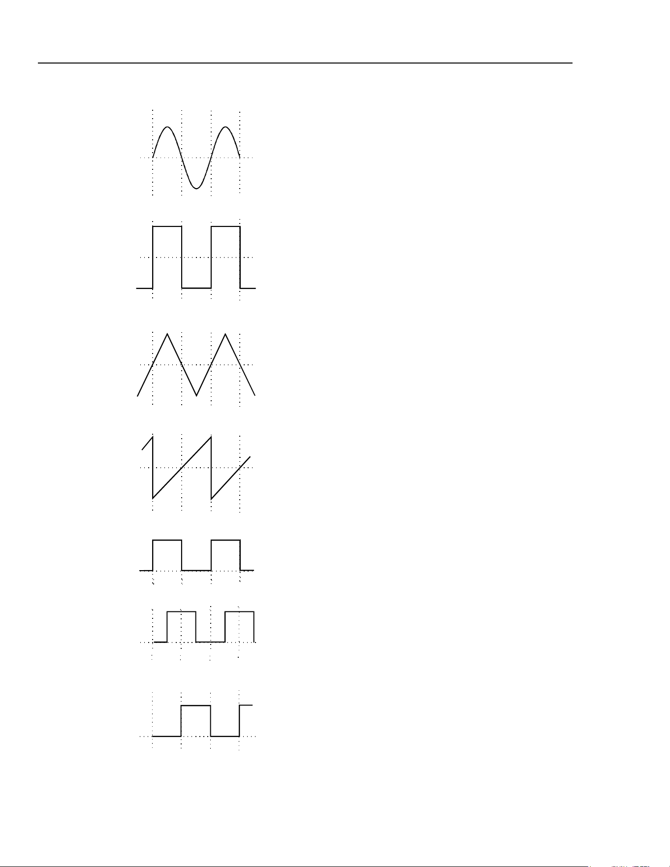
271
Users Manual
Auxiliary Output Phase
sha0004f.emf
Sine
sha0005f.emf
Square
sha0006f.emf
Triangle
sha0007f.emf
Ramp
sha0008f.emf
AUX 0°
sha0009f.emf
AUX 90°
0º 180º 360º
sha0010f.emf
AUX
180°
The convention adopted for phase in this
instrument is illustrated in the diagram. 0 ° is
always the first data point in waveform memory.
On symmetrical waveforms 0 ° is the rising edge
zero-crossing point for sine, square, triangle and
pulse waveforms; on ramps, staircases and
arbitrary waveforms 0 ° is always the start point.
When the phase is set to 0 ° the rising edge of the
AUX OUT
square wave is also at 0 °. When the
phase is set to a positive value, e.g. +90 °, the
AUX OUT
square wave lags MAIN OUT by 90°,
when the phase is set to a negative value
AUX OUT
leads MAIN OUT.
The phase is set by pressing the
EDIT key
followed by
TRIG to select the trigger edit menu;
the edit cursor is then moved to the PHASE field
using the
FIELD keys. Phase can be entered
directly from the keyboard, using the +/- key to
change the sign if necessary, or by rotary control.
Above 30 kHz the
AUX OUT accompanying sine,
triangle, square and pulse waveforms is
automatically switched such that it is derived from
the comparator (driven by the DDS sine wave)
used to generate higher frequency
MAIN OUT
square waves and pulses. The DDS Principles
section gives further information. This ensures a
jitter-free
AUX OUT signal up to the maximum
frequency of the generator but it also means that
phase shifting between
MAIN OUT and
AUX OUT
is no longer possible.
This constraint can be overridden by changing the
setting on the OPTions menu from
AUX OUTPUT=AUTO to
AUX OUTPUT=LOW FREQ; the
AUX OUT
signal then continues to be generated
independently, with phase adjustable with respect
to the
MAIN output, although clock jitter will
become increasingly significant at higher
frequencies. Changing AUTO settings is
described more fully in the next section, Waveform
Generator Options.
The
AUX OUT signal accompanying ramp,
staircase and arbitrary waveforms is, by default,
always generated independently; phase shift is
adjustable across the frequency range but again
clock jitter becomes increasingly significant at
higher frequencies
5-8
1.888.610.7664 sales@GlobalTestSupply.com
Fluke-Direct.com

Main Generator Operation
Waveform Generation Options 5
Waveform Generation Options
A number of parameters are, by default, switched automatically either when the
frequency is set above 30 kHz or when the operating mode is changed such that the best
overall performance is achieved across the whole generator frequency range. The DDS
Principles section in chapter 4, General Operation, gives further information on the 30
kHz changeover.
In addition, triangle, ramp, staircase and arbitrary waveforms are inhibited from being set
above 100 kHz, in order to ensure that they are not used accidentally at frequencies where
the wave shape is noticeably deteriorating. In all cases, however the default choice can be
overridden by the user by changing the setting on the OPTions menu.
SQWAVE GEN=A
UTO
FILTER=AUTO
AUX=AUTO FSTOP=ON
SWEEP TGEN OUT=AUTO
The OPTions edit menu shown above is selected by pressing the
EDIT key followed by
OPTN
(on the 1 numeric key).
The following descriptions, grouped together in this section for reference convenience,
should be read in conjunction with the main explanation of the appropriate parameter
elsewhere in this manual.
Each parameter is altered by moving the edit cursor to the appropriate field with the
FIELD
keys and using the DIGIT keys or rotary control to change the setting.
Square Wave Generation
In LOW FREQency mode the square wave and pulse waves are generated digitally; in this
way precision square waves can be generated down to very low frequencies without the
edge uncertainty that would be associated with conventional ramp-and-comparator
techniques. Above approximately 27 kHz (clock frequency 27.487 MHz divided by
1024) the waveforms are sampled and the 1 clock (36ns) uncertainty introduces edge
jitter which becomes increasingly significant at higher frequencies.
In HIGH FREQuency mode the square wave and pulses are derived from the output of a
comparator driven by the DDS-generated sine wave. The sine wave is, by default, filtered
and jitter-free; the high frequency square wave and pulse waveforms are thus also jitter
free.
In AUTO mode (the default) the generation of square and pulse waveforms is
automatically switched from low to high frequency mode when the frequency exceeds
30 kHz. However, when these waveforms are used in sweep and FSK modes, over a
frequency range which includes the 30 kHz changeover point, the generation mode will
not change even though AUTO is selected. Instead, the mode in use before sweep or
FSK are turned on is maintained across the frequency range. This can of course be
overridden by selecting either high or low frequency mode on the OPTions menu, as
described above.
The generator contains a 7-stage elliptical filter which exhibits a sharp cut-off beyond the
maximum generator frequency, reducing intermodulation, spurious and clock harmonics
Filter
5-9
1.888.610.7664 sales@GlobalTestSupply.com
Fluke-Direct.com

271
Users Manual
5-10
to a very low level. With the default condition of FILTER=AUTO set on the OPTion
menu, the filter is switched in automatically for sine, triangle, high frequency square
wave and high frequency pulse waveforms (although the square and pulse waveforms
themselves are not passed through the filter); the filter is automatically switched out for
low frequency square and pulse waveforms, ramps, staircases and arbitrary waveforms
because of the degrading effect it has on fast transitions. However, for all these
waveforms the filter can be set to be always on (FILTER=ON) or always off
(FILTER=OFF); this has the advantage that, for example, an arbitrary waveform with an
essentially sinusoidal content can be output with the filter on.
When NOISE is selected (see chapter 10, Special Waveforms), this 7-stage filter is
always off, whatever the FILTER= setting, and a simple 700 kHz low pass RC filter is
switched in instead.
Auxiliary Output
When sine, triangle, square wave or pulse waveforms are selected and with AUX=AUTO
the auxiliary output square wave generation switches automatically at 30 kHz from DDS
generation to a signal derived from a comparator driven by the DDS sine wave; the
advantages of this approach are the same as those explained earlier. However, as
explained above in the Auxiliary Output Phase section, the high frequency generation
mode has the disadvantage that a phase difference can no longer be set between
AUX OUT
and MAIN OUT. The automatic switchover at 30 kHz can therefore be
overridden by setting AUX=LOFRQuency, to maintain it in true DDS mode, or
AUX=HIFRQuency to lock it in high frequency mode. With AUX=AUTO there is no
automatic mode changeover if ramp, staircase or arbitrary waveforms are selected; high
frequency mode can however be forced by setting AUX=HIFRQ.
Note that there is some second order interaction between the square wave generation,
filter and auxiliary output settings which demands a little thought before deviations from
the default conditions are applied. For example, if SQWAVE GEN and AUX options
are set to AUTO but FILTER is set to OFF the edges of both the MAIN OUT and
AUX OUT square waves will exhibit some jitter at high frequencies (e.g. 1 MHz)
because the sine wave driving the comparator from which both are derived will itself be
subject to some jitter.
Frequency Stop
In the default mode of FSTOP=OFF there are no frequency limits on any waveform and
the frequency and waveform can be set as described in the Main Generator section;
waveform quality will however deteriorate progressively as the frequency increases for
certain waveforms, as discussed in the DDS Principles section.
With FSTOP=ON the maximum settable frequency for triangle, ramp, staircase and
arbitrary is limited to 100 kHz. An error message will be shown if an attempt is made to
enter a frequency above 100 kHz whilst one of these waveforms is selected, or if an
attempt is made to select one of these waveforms with the frequency already set above
100 kHz. This mode is useful in ensuring that frequencies are not accidentally set too
high for waveforms whose quality will deteriorate above 100 kHz, the frequency to
which their specifications apply.
Trigger/Sweep Output
With SWEEP/TGEN=AUTO the function of the rear panel
TRIG/SWEEP OUT socket
changes automatically when the operating mode is changed between sweep, hop and any
other mode; the two functions of this output are described in chapter 3, Connections.
1.888.610.7664 sales@GlobalTestSupply.com
Fluke-Direct.com

Main Generator Operation
Waveform Generation Options 5
5-11
When SWEEP/TGEN=SWEEP is set the TRIG/SWEEP OUTput is always in the
sweep mode if sweep is operational, or hop mode if HOP is on; when
SWEEP/TGEN=TRIG the
TRIG/SWEEP OUTput always outputs the internal trigger
generator signal.
Note that, except when using the internal trigger generator in trigger, gate, FSK or AM
modes, this signal is not synchronized with the main generator.
1.888.610.7664 sales@GlobalTestSupply.com
Fluke-Direct.com

271
Users Manual
5-12
1.888.610.7664 sales@GlobalTestSupply.com
Fluke-Direct.com

6-1
Chapter 6
Sweep Operation
Title Page
Introduction........................................................................................................ 6-2
Connections for Sweep Operation..................................................................... 6-2
Setting Sweep Span and Markers ...................................................................... 6-2
Setting Sweep Mode, Ramp Time and Source .................................................. 6-3
Frequency Stepping Resolution......................................................................... 6-4
1.888.610.7664 sales@GlobalTestSupply.com
Fluke-Direct.com

271
Users Manual
6-2
Introduction
DDS operation gives the significant advantage over conventional function generators of
phase-continuous sweeps over very wide frequency ranges, up to 10
10
:1. However it must
be remembered that the frequency is actually stepped, not continuously swept, and
thought needs to be given as to what the instrument is actually doing when using extreme
combinations of sweep time and frequency span. Refer to Frequency Stepping Resolution
at the end of this chapter for additional information.
Sweep mode is turned on and off with alternate presses of the
SWEEP key; the lamp
beside the key lights when sweep mode is on. The sweep parameters (begin, end and
marker frequencies, sweep direction, law, ramp time and source) are all set from the
sweep edit menu which is selected by pressing the
EDIT key followed by the SWEEP
key. When sweep edit is selected the lamp beside the SWEEP key flashes to show edit
mode, regardless of whether sweep operation is selected to be on or off. The sweep mode
parameters are set up on two pages of the display; the flashing edit cursor is moved
around each page, and between pages, by the
FIELD and DIGIT keys as described in the
Principles of Editing section in chapter 4, General Operation.
Return to the main menu from either page of the edit menu is achieved by pressing the
ESCAPE
key.
See also Square Wave Generation in chapter 5, Main Generator Operation, for
information concerning the use of sweep with square waves.
Connections for Sweep Operation
Sweeps are usually used with an oscilloscope or hard-copy device to investigate the
frequency response of a circuit. The instrument's
MAIN OUT is connected to the circuit
input and the circuit output is connected to an oscilloscope or, for slow sweeps, a
recorder.
To show the markers on the display instrument the rear panel
TRIG/SWEEP OUT
socket should be connected to a second channel; an oscilloscope should be triggered from
this channel (negative edge). Alternatively, if no marker display is required, the
TRIG/SWEEP OUT
can be connected directly to the external trigger of the
oscilloscope.
The
TRIG/SWEEP OUT socket provides a 3-level waveform in sweep mode. The
output changes from high (4 V) to low (0 V) at the start of the sweep and goes high again
at the end of the sweep. If the display device is a chart recorder
TRIG/SWEEP OUT can
therefore be used as a pen-lift signal (note that it may be necessary to invert the signal).
Additionally the
TRIG/SWEEP OUT output provides narrow 1 V pulses at each marker
frequency, as described in the next section.
For externally triggered sweeps a trigger signal must be provided at the front panel
EXT TRIG
socket. A sweep is initiated by the rising edge of the trigger signal.
The generator does not provide a ramp output for use with X-Y displays or recorders.
Setting Sweep Span and Markers
Pressing the EDIT key followed by the SWEEP key displays the first page of the sweep
parameters with values set to factory defaults.
1.888.610.7664 sales@GlobalTestSupply.com
Fluke-Direct.com

Sweep Operation
Setting Sweep Mode, Ramp Time and Source 6
6-3
BEG FRQ=100.0000kHz
END FRQ=10.00000MHz
MARK FRQ=5.000000MHz
MORE->>>
The
BEGin, END, and MARKER frequencies can all be set or modified in exactly the
same way as described for the setting of the frequency in chapter 5, Main Generator
Operation.
In summary, with the cursor in the first field of any line, the
DIGIT keys or rotary control
will alternate the display between
FRQ= and PER=; with the cursor in the numeric
field the
DIGIT keys will move the cursor within the field and the rotary control will
change the value in increments determined by the cursor position; with the cursor in the
units field, the
DIGIT keys or rotary control will change the value in decade increments.
Direct keyboard entries (numeric digits plus units) will be accepted with the cursor
anywhere in the line of the display. Note that if sweep mode is actually on (alternate
presses of the
SWEEP key toggle the sweep on and off) and the ramp time is set to
200 ms or less, then changing the
BEGin or END frequency causes the current sweep to
be aborted, the frequency steps to be recalculated, and a new sweep started at each
frequency change; it is therefore quicker to make changes with the sweep switched off.
The
MARK FRQ can, however, be changed without interrupting the sweep.
A second marker is also displayed at the frequency set on the main menu, i.e. at the
frequency set for the generator in non-sweep mode. This offers the advantage of a marker
adjustable from the same menu used to control amplitude, offset, etc.
The marker signal is output from the rear panel
TRIG/SWEEP OUT socket. The output
is low (0 V) for the duration of the sweep, with narrow 1 V pulses at the marker
frequency.
Note that the marker pulse width is that of the duration of that frequency step which has
the closest value to the marker frequency. This means that sweeps with few steps will
have wider markers than those with many steps. Refer to Frequency Stepping Resolution
below for additional information.
Setting Sweep Mode, Ramp Time and Source
Pressing the FIELD keys to move the cursor through each editable field of the first page
of the sweep menu eventually steps the cursor onto the second page:
MODE=BEG-END LAW=LOG
RAMP TIME=0.05 S
TRIG SRC=CONTINUOUS
MORE->>>
Pressing the left
FIELD key with the cursor in the first (MODE) field will return the edit
cursor to the last field on the first page of the sweep menu. Pressing the right
FIELD key
will step the cursor through all the editable fields up to
TRIG SRC (trigger source);
one more press returns the cursor to the first field of the first page.
Pressing
ESCAPE always exits the edit menu and returns to the main menu.
1.888.610.7664 sales@GlobalTestSupply.com
Fluke-Direct.com

271
Users Manual
6-4
With the edit cursor in the MODE field, alternate presses of the DIGIT keys, or turning
the rotary control, will set the sweep direction to
BEG-END (beginning to end) or
END-BEG
(end to beginning). There are no restrictions on the BEGin or END
frequencies; this means that because the BEGin frequency can be higher than the END
frequency, the MODE field simply provides an easy way to reverse the sweep direction.
With the edit cursor in the
LAW field the sweep can be changed from LINear to
LOG
arithmic. With LAW=LIN set, the frequency changes linearly with time across the
sweep; with
LAW=LOG set, the frequency changes exponentially with time across the
sweep. The term ‘log sweep’ is a convention; with the start frequency lower than the stop
frequency (the usual mode of operation) the mathematical relationship of frequency to
time is actually antilog.
The sweep rate is set with the cursor in the
RAMP TIME field; ramp time can be set
with 3 digit resolution from 0.01 s (10 ms) to 999 s. The choice of ramp time affects the
number of discrete frequency steps in the sweep; faster sweeps will have fewer steps.
The trigger mode of the sweep is set with the cursor in the
TRIG SRC (trigger source)
field; the options are
CONTINUOUS, EXTernal and MAN/REMOTE. In CONTINUOUS
mode the sweep starts simultaneously with the high-to-low transition of the
TRIG/SWEEP OUT
signal; the sweep starts with the phase at 0 ° and at the output level
set by the dc offset. At the end of the sweep the signal returns to this dc offset level and
the
TRIG/SWEEP OUT signal simultaneously goes high again. After a delay (long
enough for an oscilloscope retrace, for example) the cycle repeats.
In
EXTernal mode the trigger source is connected to the front panel EXT TRIG socket.
A sweep starts typically 200 to 800 µs after the rising edge of the trigger signal; the
sweep is completed before another trigger edge is recognized and a new sweep initiated.
The minimum trigger pulse width is 1 ms and the repetition rate should be greater than
110 % of the sweep time plus 5 ms.
In
MAN/REMOTE mode a single sweep is initiated by each press of the MAN/SYNC
key or by each remote command. If the MAN/SYNC key is pressed during a sweep
(continuous or single sweep) the sweep will be paused at the instantaneous sweep
frequency until
MAN/SYNC is pressed again to allow the sweep to continue.
Frequency Stepping Resolution
The generator frequency is stepped, not continuously swept, between the BEGin and
END
frequencies. The number of discrete frequency steps in a sweep is determined by
the ramp time selected on the sweep edit menu; the size of each step, i.e. the frequency
stepping resolution, is determined by the number of steps and the sweep span.
For the fastest sweeps, in the range 10 ms to 200 ms, the frequency steps are pre-
calculated and output at 125 µs intervals; this means that there are 80 discrete steps in a
10 ms sweep, 160 in a 20 ms sweep, and so on up to 1600 steps in a 200 ms sweep.
For slower sweeps, up to 999s, each frequency step is calculated on-the-fly and output
every 5 ms; this means that there are 100 steps in a 500 ms sweep, 200 in a 1 s sweep,
and so on up to 199,800 steps in a 999 s sweep.
Note that at the fastest sweep rates, with fewest frequency steps (e.g. 10 ms sweep) two
effects can occur at extremes of frequency span which are not experienced with
conventional generators. Firstly, if the scan is very wide the frequency changes will be
quite large at each step; if the output is applied to a filter, for example, the response will
be a succession of step-change levels with (at higher frequencies) many cycles of the
same frequency at each step. Secondly, if the begin frequency is less than 800 Hz (the
ramp rate for fast sweeps), one or more of the low frequency steps will contain
incomplete cycles. These effects are only created because of the very wide sweeps that
1.888.610.7664 sales@GlobalTestSupply.com
Fluke-Direct.com

Sweep Operation
Frequency Stepping Resolution 6
6-5
can be achieved with DDS techniques; analogue generators usually have more restricted
capabilities.
Note also that because the marker pulse duration (from the rear panel
TRIG/SWEEP OUT
socket) is that of the nearest frequency step, fast sweep rates with
few steps will have wider marker pulses.
1.888.610.7664 sales@GlobalTestSupply.com
Fluke-Direct.com

271
Users Manual
6-6
1.888.610.7664 sales@GlobalTestSupply.com
Fluke-Direct.com

7-1
Chapter 7
Triggered Burst and Gate
Title Page
Introduction........................................................................................................ 7-2
Internal Trigger Generator............................................................................. 7-2
External Trigger Input................................................................................... 7-2
Triggered Burst.................................................................................................. 7-2
Trigger Source............................................................................................... 7-3
Burst Count.................................................................................................... 7-3
Start/Stop Phase............................................................................................. 7-3
Gated Mode........................................................................................................ 7-4
Gate Source ................................................................................................... 7-4
1.888.610.7664 sales@GlobalTestSupply.com
Fluke-Direct.com

271
Users Manual
7-2
Introduction
In burst mode a defined number of cycles follow each trigger event. This mode is edge
triggered.
In gated mode the generator runs while the gating signal is high. This mode is level
sensitive.
Both burst and gated modes can be controlled by either the internal trigger generator, an
external trigger input, by the front panel
MAN/SYNC key or by remote control.
Internal Trigger Generator
The internal trigger generator divides down a crystal oscillator to produce a 1:1 square-
wave with a period from 0.02 ms (50 kHz) to 200 s (0.005 Hz). Generator period entries
that cannot be exactly set are accepted and rounded up to the nearest available value, e.g.
0.109 ms is rounded to 0.12 ms. The generator output is available as a TTL level signal at
the rear panel
TRIG/SWEEP OUT socket.
In burst most the rising edge of each cycle of the trigger generator is used to initiate a
burst; the interval between bursts is therefore 0.02 ms to 200 s as set by the generator
period.
In gated mode the output of the main generator is gated on whilst the trigger generator
output is high; the duration of the gate is therefore 0.01 ms to 100 s in step with trigger
generator periods of 0.02 ms to 200 s.
External Trigger Input
External trigger or gate signals are applied to the front panel
EXT TRIG input which has
a TTL level (1.5 V) threshold. In triggered burst mode the input is edge sensitive; the
rising edge of each external trigger initiates the specified burst. In gated mode the input is
level sensitive; the output of the main generator is on whilst the gate signal is high
(>1.5 V).
The minimum pulse width that can be used with the
EXT TRIG input is 50 ns and the
maximum repetition rate is 1 MHz. The maximum signal level that can be applied
without damage is ±10 V.
Triggered Burst
Triggered burst mode is turned on and off with alternate presses of the TRIG key; the
lamp beside the key lights when triggered mode is on. The triggered mode parameters
(trigger source, internal trigger generator, burst count and start/stop phase) are all set
from the trigger edit menu which is selected by pressing the
EDIT key followed by the
TRIG
key. When trigger edit is selected the lamp beside the TRIG key flashes to show
edit mode regardless of whether triggered burst operation is currently selected to be on or
off.
SOURCE=EXT
TGEN=1.00ms 1.000kHz
BURST COUNT= 0001
PHASE=+000° (+000°)
1.888.610.7664 sales@GlobalTestSupply.com
Fluke-Direct.com

Triggered Burst and Gate
Triggered Burst 7
7-3
Trigger Source
With the edit cursor in the
SOURCE field of the trigger edit menu, the DIGIT keys or
rotary control can be used to select
EXTernal, MAN/REMOTE, or TGEN (internal
trigger generator) as the trigger source.
With the source set to
EXTernal, the specified burst is triggered by the rising edge of a
trigger signal applied to the
EXT TRIG input (see External trigger input above). With
the source set to
MAN/REMOTE, a burst can be initiated by pressing the front panel
MAN/SYNC
key or by the appropriate command via the RS232 or GPIB interfaces.
With the source set to
TGEN, the burst is triggered internally as described above in the
Internal trigger generator section. The period of the internal generator is set in the
TGEN
field on the second line of the edit menu. With the cursor in the numeric field the
DIGIT
keys will move the cursor within the field and the rotary control will change the
value in increments determined by the cursor position; with the cursor in the units field
the
DIGIT keys or rotary control will change the value in decade increments. Direct
keyboard entries (number plus units) will be accepted with the cursor in either field.
Beside the generator period value the equivalent frequency is shown; this is for
information only and is not an editable field.
Because the internal trigger generator can be used by the trigger, gate, FSK and AM
functions, and can be set from their respective edit menus, an information field is
displayed in brackets beside
TGEN when this is selected as the source. This field will
show
[FREE] when TGEN is not used elsewhere, or one of the four letters G, F, A
or
T to indicate that the generator is currently set as the source on the GATE, FSK,
AM
, or TRIG menus respectively, in addition to the menu currently displayed.
Burst Count
The number of complete cycles in each burst following the trigger is set with the edit
cursor in the
BURST COUNT field. Entries can be made directly from the keyboard or
by rotary control; the burst range is 1 to 1023 with a resolution of 1 cycle or 0.5 to 511.5
with a resolution of 0.5 cycles. The first cycle starts, and the last cycle stops, at the phase
set in the
PHASE field.
Start/Stop Phase
The start and stop phase of the triggered burst is set in the
PHASE field. The field
actually contains the phase of the auxiliary output and it is from this output that control of
the start and stop point of the main generator is derived; the rising edge of the AUX OUT
signal, which can be phase shifted with respect to the MAIN OUT, determines the start
and stop point of the main waveform burst. Consequently, the conditions under which the
auxiliary output phase shift is constrained, and which are fully explained in that section,
all apply to start/stop phase. For example, the start/stop phase of sine and triangle
waveforms cannot be adjusted for main output frequencies above 30 kHz unless the
AUX OUTPUT
field on the options menu is set to LOW FREQuency generation mode
because only in this mode does the
AUX OUT continue to be phase shifted with respect
to
MAIN OUT.
Because the phase control signal is derived from the auxiliary output waveform further
considerations apply as the main generator frequency is increased. With
AUX OUTPUT=LOW FREQ
on the Options menu, phase shift control is still
available above 30 kHz but real hardware delays become increasingly significant such
that the start/stop phase increases for no change in phase setting; this shift is caused by
the delay between
AUX OUT and MAIN OUT becoming more significant and by the
delays in the burst count and phase control circuits themselves. These delays can be
equivalent to a phase shift of about +45 ° at 1MHz; however, by ‘backing off’ the
1.888.610.7664 sales@GlobalTestSupply.com
Fluke-Direct.com

271
Users Manual
7-4
required phase shift by -45 ° the desired condition can still be achieved. At the same time,
however, the reduction in the number of samples making up each cycle of the waveform
means that the start/stop point covers a region of uncertainty which is 1 clock wide.
Note that these effects apply even when the phase is set to 0 °; at frequencies approaching
10 MHz the phase shift can be 90 ° or more and the uncertainty band becomes wide.
Because this effect is seen at 0 ° phase it is also evident when the auxiliary output is in
HIGH FREQ
uency mode, i.e. when there is no phase control. In fact, because the
AUX OUT
signal is derived from the filtered DDS sine wave in this mode the filter adds
further phase delay, creating even longer phase shifts at a given frequency than are
evident with
AUX OUTPUT in LOW FREQuency mode.
In summary, phase errors and uncertainty will increase as the main frequency is increased
above 30 kHz, even with 0 ° phase set. However, stop/start phase control can be used,
with care, to much higher frequencies by ‘backing-off’ the phase to compensate for the
hardware delays.
Gated Mode
Gated mode is turned on and off with alternate presses of the GATE key; the lamp beside
the key lights when gate mode is on.
The selection of the gate source signal is made from the gate edit menu which is selected
by pressing the
EDIT key followed by the GATE key. when gate edit is selected the
lamp beside the
GATE key flashes to show edit mode regardless of whether gate
operation is currently selected to be on or off.
SOURCE=EXT
TGEN=1.00ms 1.000kHz
Gate Source
With the edit cursor in the
SOURCE field of the gate edit menu, the digit keys or rotary
control can be used to select
EXTernal, MAN/REMOTE, or TGEN (Trigger GENerator)
as the gate source. In all cases, when the gate condition is true, the main generator signal
is gated through to the MAIN OUT socket. Since the main generator is free-running and
not synchronized with the gate source the start and stop phase of the waveform is entirely
arbitrary; there will be an instantaneous transition from the dc offset level to the current
waveform phase at the start of the gating period and an instantaneous transition back to
the dc offset level at the stop.
With the source set to
EXTernal, the generator waveform is gated on whilst the external
signal applied to the
EXT TRIG input exceeds the gate threshold (1.5 V) (see External
trigger input above).
With the source set to
MAN/REMOTE, the generator waveform is gated on and off with
alternate presses of the
MAN/SYNC key or by the appropriate commands via the RS232
or GPIB interfaces.
With the source set to
TGEN, the generator waveform is gated on as explained in the
Internal trigger generator section; the trigger generator is set exactly as described in the
Trigger source section.
1.888.610.7664 sales@GlobalTestSupply.com
Fluke-Direct.com

8-1
Chapter 8
Amplitude Modulation
Title Page
Introduction........................................................................................................ 8-2
Amplitude Modulation (Internal)....................................................................... 8-2
Modulation Frequency................................................................................... 8-2
Modulation Depth.......................................................................................... 8-2
Modulation Waveform .................................................................................. 8-3
VCA (External).................................................................................................. 8-3
1.888.610.7664 sales@GlobalTestSupply.com
Fluke-Direct.com

271
Users Manual
8-2
Introduction
Two modes of operation are available from the AM menu:
1. Amplitude modulation using the internal trigger generator as the modulation source
in which the modulation depth is expressed as a percentage and constant modulation
depth is maintained as the main generator (carrier) amplitude is varied.
2. VCA (voltage controlled amplitude) mode, in which the main generator amplitude is
directly proportional to the external modulating signal voltage applied to the rear
panel
VCA IN socket. Suppressed carrier modulation (SCM) is achievable in this
mode.
AM mode is turned on and off with alternate presses of the
AM key; the lamp beside the
key lights when
AM mode is on. The AM parameters are all set from the AM edit menu
which is selected by pressing the
EDIT key followed by the AM key. When AM edit is
selected the lamp beside the
AM key flashes to show edit mode regardless of whether
AM mode is currently selected to be on or off.
SOURCE=EXT VCA
TGEN=1.00ms 1.000kHz
INT MOD DEPTH=030%
INT MOD=SQUARE
Amplitude Modulation (Internal)
With the edit cursor in the SOURCE field of the AM edit menu the DIGIT keys or rotary
control can be used to toggle the source between
EXT VCA and TGEN (Trigger
GENerator) i.e. between external VCA mode and internal AM mode.
Modulation Frequency
Select
TGEN in the SOURCE field and move the cursor to the TGEN field to set the
period of the internal trigger generator, the modulation source for internal AM. The
internal trigger generator produces a square wave with a period that can be set from
0.02 ms (50 kHz) to 200 s (0.005 Hz). Period entries that cannot be exactly set are
accepted and rounded up to the nearest available value, for example 0.109 ms is rounded
to 0.12 ms. The generator output is available as a TTL level signal at the rear panel
TRIG/SWEEP OUT
socket.
Beside the generator period value the equivalent frequency is shown; this is for
information only and is not an editable field.
Because the internal trigger generator can be used by the trigger, gate, FSK and AM
functions, and can be set from their respective edit menus, an information field is
displayed in brackets beside
TGEN when this is selected as the source. This field will
show
[FREE] when TGEN is not used elsewhere, or one of the four letters G, F, A
or
T to indicate that the generator is currently set as the source on the GATE, FSK,
AM
, or TRIG menus respectively, in addition to the menu currently displayed.
Modulation Depth
Move the edit cursor to the
INT MOD DEPTH field to set the modulation depth
between 1 % and 100 % in 1 % increments. The maximum output (20 V p-p into an open
circuit) cannot be exceeded and clipping will occur if modulation attempts to drive the
1.888.610.7664 sales@GlobalTestSupply.com
Fluke-Direct.com

Amplitude Modulation
VCA (External) 8
8-3
output beyond this limit. The maximum generator output setting at which correct
operation is maintained reduces from 20 V p-p to 10 V p-p (open circuit) as the
modulation is increased from 0 % to 100 %.
Modulation Waveform
The default modulation waveform is a square wave because this permits the full
frequency range of the internal trigger generator to be used. Alternatively, a fixed 1 kHz
sine wave can be selected by moving the edit cursor to the
INT MOD field in the last
line of the display; the
DIGIT keys or rotary control can be used to toggle the setting
between
SQUARE (at the frequency set on the internal trigger generator) and SINE.
Note that selecting
SINE forces the TGEN field to display 1.00ms 1.000kHz
but the user setting is not lost and if INT MOD= SQUARE is reselected the TGEN
setting returns to its original value.
VCA (External)
With the cursor in the SOURCE field of the AM edit menu, set the source to
EXT VCA
. Connect the modulating signal to the rear panel VCA IN socket (nominal
6 kΩ input impedance); a positive voltage increases the generator output and a negative
voltage decreases the output. Note that as with internal AM, clipping will occur if the
combination of generator setting and VCA signal attempts to drive the output above
20 V p-p (open circuit).
External AM is achieved by setting the generator to the required output level and
applying the modulation signal (which may be ac coupled if required) at the appropriate
level to obtain the modulation depth required. If the generator output level is changed the
amplitude of the modulating signal will have to be changed to maintain the same
modulation depth. As with internal AM, the maximum output setting of the generator at
which clipping is avoided is reduced from 20 V p-p to 10 V p-p (open circuit) as
modulation is increased from 0 % to 100 %. Modulation frequency range is dc to
100 kHz.
The generator’s amplitude control circuit has four quadrant operation, allowing the
generator output to be inverted if the external VCA voltage is taken sufficiently negative.
Suppressed carrier modulation (SCM) can be achieved by applying a modulating signal
with a negative offset between 0 V and -3 V (depending on output level setting) sufficient
to reduce the carrier output to zero.
It is also possible to modulate a dc level from the generator with a signal applied to
VCA IN
, as follows. Set the generator to 0 Hz sine wave on the main menu and +90 °
phase on the trigger menu. Select
EXT TRIG (the default) and turn trigger mode on
with the
TRIG key but do not apply a trigger signal. The MAIN OUT is now set at the
peak positive voltage defined by the amplitude setting on the main menu; setting -90 °
phase on the trigger menu will give the peak negative voltage. Select
EXT VCA on the
AM edit menu and turn AM on; the dc level will now be modulated by the signal applied
to the
VCA IN socket.
1.888.610.7664 sales@GlobalTestSupply.com
Fluke-Direct.com

271
Users Manual
8-4
1.888.610.7664 sales@GlobalTestSupply.com
Fluke-Direct.com

9-1
Chapter 9
FSK
Title Page
Introduction........................................................................................................ 9-2
Frequency Setting.......................................................................................... 9-2
Trigger Source............................................................................................... 9-2
1.888.610.7664 sales@GlobalTestSupply.com
Fluke-Direct.com

271
Users Manual
9-2
Introduction
FSK (Frequency Shift Keying) mode permits fast phase-continuous switching between
two frequencies. All other parameters of the waveform (amplitude, offset, symmetry) are
unchanged as the frequency is switched. For switching between waveforms where all
parameters can change, refer to chapter 11, Hop.
FSK can be controlled by the internal trigger generator, by an external trigger input, by
the front panel
MAN/SYNC key or by remote control.
FSK mode is turned on and off with alternate presses of the
FSK key; the lamp beside
the key lights when FSK mode is on. The FSK mode parameters (frequencies, trigger
source and internal trigger generator) are all set from the FSK edit menu which is
selected by pressing the
EDIT key followed by the FSK key. When FSK edit is selected
the lamp beside the
FSK key flashes to show edit mode regardless of whether FSK mode
is currently selected to be on or off.
FREQ A=10.00000kHz
FREQ B=10.00000MHz
SOURCE=EXT
TGEN=1.00ms 1.000kHz
Frequency Setting
The two frequencies,
FREQ A and FREQ B, between which the waveform is
switched, are set in exactly the same way as the frequency on the main menu; in fact,
FREQ A is the main generator frequency in non-FSK mode and changing FREQ A on the
FSK edit menu will also change the frequency shown on the main menu.
Trigger Source
With the edit cursor in the
SOURCE field of the FSK edit menu, the DIGIT keys or
rotary control can be used to select
EXTernal, MAN/REMOTE, or TGEN (internal
Trigger GENerator) as the trigger source which controls the frequency shifting.
With the source set to
EXTernal the frequency is switched at each rising edge of the
signal applied to the
EXT TRIG input. The minimum pulse width that can be used with
the
EXT TRIG input is 50 ns and the maximum repetition rate is 1 MHz.
With the source set to
MAN/REMOTE, the frequency is switched with each press of the
front panel
MAN/SYNC key or by the appropriate command via the RS232 or GPIB
interfaces.
With the source set to
TGEN, the frequency is switched at each rising edge of the internal
trigger generator; the trigger generator produces a square wave with a period that can be
set from 0.02 ms (50 kHz) and 200 s (0.005 Hz). Period entries that cannot be exactly set
are accepted and rounded up to the nearest available value, for example 0.109 ms is
rounded to 0.12 ms. The generator output is available as a TTL level signal at the rear
panel
TRIG/SWEEP OUT socket.
Setting the frequency of the internal trigger generator is fully described in the Trigger
source section of chapter 7, Triggered Burst and Gate.
Because the internal trigger generator can be used by the trigger, gate, FSK and AM
functions, and can be set from their respective edit menus, an information field is
displayed in brackets beside
TGEN when this is selected as the source. This field will
1.888.610.7664 sales@GlobalTestSupply.com
Fluke-Direct.com

FSK
Introduction 9
9-3
show [FREE] when TGEN is not used elsewhere, or one of the four letters G, F, A
or
T to indicate that the generator is currently set as the source on the GATE, FSK,
AM
, or TRIG menus respectively, in addition to the menu currently displayed.
1.888.610.7664 sales@GlobalTestSupply.com
Fluke-Direct.com

271
Users Manual
9-4
1.888.610.7664 sales@GlobalTestSupply.com
Fluke-Direct.com

10-1
Chapter 10
Special Waveforms
Title Page
Staircase............................................................................................................. 10-2
Arbitrary............................................................................................................. 10-3
Recalling Arbitrary Waveforms .................................................................... 10-3
Storing Arbitrary Waveforms........................................................................ 10-3
Noise.................................................................................................................. 10-4
1.888.610.7664 sales@GlobalTestSupply.com
Fluke-Direct.com

271
Users Manual
10-2
Staircase
Staircase, or multilevel square waves, are selected by pressing the STAIR key; when
STAIR
is selected the lamp beside the key lights. The default staircase is a 4-level
waveform with level changes at 90 ° intervals; to modify or define a new staircase select
the staircase edit menu by pressing the
EDIT key followed by STAIR. When staircase
edit is selected the lamp beside the
STAIR key flashes to show edit mode; selecting edit
mode always sets staircase on and symmetry to 50 % to permit visual checking of the
waveform.
VALS=ABS AUTO=YES
STEP=00 ACTIVE
LENGTH=0256
LEVEL=+511
The staircase edit menu is shown above. Up to 16 steps can be defined, numbered 00 to
15, with a length and level specified either in absolute terms or as a percentage of full
scale height and cycle length. When the value is set to
ABSolute in the VALS field the
LENGTH
field will accept numbers in the range 0000 to 1024 (the cycle sample length)
and the
LEVEL field will accept values in the range -512 to +511, i.e. 10-bit resolution
peak-to-peak; -512 and +511 correspond to -10 V and +10 V peaks respectively with the
amplitude on the main menu set to maximum. Note, however, that the actual peak-peak
voltage will be determined by the actual amplitude setting. When the value is set to
%MAX
in the VALS field both the length and level fields will accept numbers in the
range 0 to 100 % in 1 % steps.
To edit the staircase, or create a new one, proceed as follows:
Move the cursor to the
STEP field and use the keyboard or rotary control to select the
first step to be changed; note that the level of the selected step is rapidly dithered during
editing (by an amount equivalent to the least significant bit) to help identify the correct
step on an oscilloscope. Move the cursor to the
LENGTH field and use the keyboard or
rotary control to enter the new length for that step in the appropriate units; press
ENTER
to enter the value. If the AUTO field has been left set at YES (the default value) the
cursor will automatically move to the
LEVEL field; enter a value in the appropriate
units and press
ENTER again. The cursor will move back to the LENGTH field and the
STEP
field will be incremented by 1 ready for the next entry. If AUTO has been set to
NO
, the stepping between LENGTH and LEVEL and the incrementing of the STEP
must be done manually.
The staircase waveform is made up from steps 00, 01, 02 ... etc., in numeric order, up to
the step whose length brings the total to 1024 or more samples; all these steps, including
any in the sequence that have zero length, will be flagged as
ACTIVE beside their step
number in the display because changing the
LENGTH or LEVEL of any of them will
affect the waveform. Those steps beyond the last active step will be flagged
INACTIVE,
even if they have a non-zero length, because changing them will not affect the waveform.
If the length of the last active step takes the total number of samples above 1024 then the
surplus samples are ignored (but the full length is displayed); if the last active sample has
insufficient samples to bring the total to 1024 then the end of the waveform is filled in
with the necessary number of samples at
LEVEL=000.
Waveform editing forces the symmetry to 50 % to simplify entry; when edit mode is
ended the waveform symmetry will return to that specified on the main menu.
1.888.610.7664 sales@GlobalTestSupply.com
Fluke-Direct.com

Special Waveforms
Arbitrary10
10-3
Arbitrary
Up to 5 user-defined arbitrary waveforms can be down-loaded via the RS232 or GPIB
interfaces and stored, together with a 16-character name in non-volatile RAM; these
waveforms occupy stores 01 to 05 inclusive. Stores 06 onwards contain a number of
frequently used arbitrary waveforms stored in ROM; these may be changed or added to
from time to time in response to user requirements.
Each arbitrary waveform is stored as 1024 points with values in the range -512 to +511,
i.e. 10-bit vertical resolution; -512 and +511 correspond to -10 V and +10 V peaks
respectively with amplitude on the main menu set to maximum. However, the actual
waveform ‘played back’ from the generator can have its amplitude, offset and symmetry
adjusted as if it were a basic sine, square, etc., waveform.
The currently recalled arbitrary waveform is selected by pressing the
ARB key; the lamp
beside the
ARB key lights to show that arbitrary mode is selected. The ARB edit menu
is used to change the currently recalled arbitrary waveform, to store new waveforms in
non-volatile RAM and to name them. The arbitrary edit menu is accessed by pressing the
EDIT key followed by ARB. When arb edit is selected the lamp beside the ARB key
flashes to show edit mode regardless of whether ARB mode is currently selected to be on
or off.
RECALL ARB NO: 14
SINX/X
ENTER TO EXECUTE
Recalling Arbitrary Waveforms
The default arb edit menu is shown above. With the edit cursor in the store number field
each store can be stepped through in turn using the rotary control or direct keyboard
entry. Each stored waveform from ROM will have a reference name in the second line of
the display, e.g.
sinx/x. The user-defined waveforms in non-volatile RAM will have
the names given by the user during the store procedure, described below.
To recall a particular waveform select the appropriate number and press
ENTER. Once
the waveform has been recalled into waveform memory it can be selected by pressing the
ARB
key and output at the frequency, amplitude, offset and symmetry defined on the
main menu.
Storing Arbitrary Waveforms
User defined waveforms can be downloaded into non-volatile RAM via the RS232 or
GPIB interface; full details are given in chapter 16, Remote Control.
Arbitrary waveforms created from the front panel, e.g. staircase waveforms, can be saved
to non-volatile RAM using the arb edit menu. With the edit cursor in the first edit field of
the menu, alternate presses of the
DIGIT keys will switch the field between RECALL
and STORE.
1.888.610.7664 sales@GlobalTestSupply.com
Fluke-Direct.com

271
Users Manual
10-4
STORE ARB NO: 01
ENTER TO EXECUTE
Pressing
ENTER changes the menu to permit a name to be entered for the waveform.
Turning the rotary control scrolls through all available characters in the selected digit
position; the
DIGIT keys are used to move the cursor to each digit position in turn.
SAVE ARB TO STORE 01
NAME: USE DIGIT/DIAL
WAVE_
ENTER TO EXECUTE
The display above shows the name
WAVE entered; when the name is complete, pressing
ENTER
saves the waveform and name in the specified store. A confirmation beep is
given and the display returns the menu to
RECALL ARB No: nn, where nn is the
store number just saved.
Noise
The generator can be set to output pseudo-random noise within the bandwidth 0.03 Hz to
700 kHz. To achieve this bandwidth a simple RC filter is always switched in instead of
the standard 7-stage filter, whatever the
FILTER = setting is on the options menu.
Amplitude and offset are adjustable and noise can be used in
GATE and AM modes.
Noise is selected from the noise menu, accessed by pressing the
EDIT key followed by
NOISE
, on the numeric 4 key. Noise is turned on and off with alternate presses of the
DIGIT
keys or by turning the rotary control. When noise is on, the lamp beside the last
used function will be off and no other function (including
STAIR and ARB) can be
selected.
Having set noise on, pressing
ESCAPE will return the instrument to the main menu; the
FREQuency field will show FREQ = WIDEBAND NOISE. Normal entries from the
keyboard can in fact be made in the frequency field but the new value will not be used
until noise is switched off. Similarly the symmetry setting can be changed while noise is
on but it will have no effect until noise is switched off.
The other parameters on the main menu can, however, be changed normally. These
include amplitude, offset and output impedance. Noise can also be used in the same way
as any other waveform in
GATE and AM modes; attempting to switch on any other
mode will bring up the warning message
Operation is illegal here, although
normal editing of all modes is still permitted.
1.888.610.7664 sales@GlobalTestSupply.com
Fluke-Direct.com

11-1
Chapter 11
Hop
Title Page
Introduction........................................................................................................ 11-2
Setting each Waveform Step.............................................................................. 11-2
Defining the Sequence and Timing.................................................................... 11-2
Running the Sequence ....................................................................................... 11-3
Timing Considerations....................................................................................... 11-3
Saving Hop Settings........................................................................................... 11-4
1.888.610.7664 sales@GlobalTestSupply.com
Fluke-Direct.com

271
Users Manual
11-2
Introduction
The hop facility allows up to 16 different waveforms to be output in sequence at a rate
determined by either the internal timer, an external trigger, a remote command or by
pressing the
MAN/SYNC key. Each waveform can be set to any wave shape, frequency,
amplitude and offset; symmetry is the same for every step in the sequence and is defined
on the main menu before Hop is selected. Frequency-only changes are phase-continuous.
Hop is both edited and controlled from the hop menu, accessed by pressing the
EDIT key
followed by
HOP (the numeric 5 key). Return to the main menu is by pressing
ESCAPE
.
Setting each Waveform Step
The hop menu is shown below. With the HOP field set to HOP:OFF the edit cursor
can be moved around all the editable fields using the
FIELD and DIGIT keys in the
standard way.
HOP:OFF n=01 01.000s
FREQ=10.00000kHz
VhiZ =+20.0 Vpp SINE
DC=+0.00mV LAST=01
The 16 steps are numbered 00 to 15. The step to be edited is selected with the edit cursor
in the
n= field using direct keyboard entries, followed by ENTER, or the rotary
control.
For each step the frequency, amplitude and offset are set up, having positioned the cursor
in the appropriate field, exactly as for the main menu; the cursor can be moved directly to
the fields of interest by pressing the
FREQ/PER, AMPL, or DC OFFSET keys as
appropriate. For further information see the Main Generator Parameters section in
chapter 5, Main Generator Operations earlier in this manual.
The other parameters of the main menu, symmetry and output impedance, are set on that
menu and are the same for every hop waveform.
The wave shape for each step is selected directly with the standard function keys or with
the cursor in the edit field to the right of the amplitude display. The
DIGIT keys or rotary
control can be used to step through each choice in turn; the corresponding lamp beside
the function key lights to confirm the selection. The currently loaded
STAIRcase and
ARB
itrary waveforms are also included in the selection sequence (between -RAMP and
SINE
) and their lamps also light when they are selected.
All parameters can be copied from one step to the next step by entering the new step in
the
n= field and pressing RECALL; the differences in the new step can then be entered
as described above. This provides a quick means of creating new steps when only one or
two parameters change.
Defining the Sequence and Timing
All 16 steps always contain a set-up, even if this is only the default setting. When set to
run the hop sequence will start at step 00 and execute steps in chronological order up to
the step number defined in the
LAST= field, after which it will go back to step 00 and
start again. The desired sequence should therefore be set starting at step 00 and the
LAST=
field should be set to the last valid step number.
1.888.610.7664 sales@GlobalTestSupply.com
Fluke-Direct.com

Hop
Running the Sequence11
11-3
Both the control mode (internal, external or manual/remote) and internal timing (if
selected) are set with the edit cursor in the rightmost field of the top line of the display;
the diagram shows the default setting of 1 s internal interval. Note that each step can be
set to a different length or a different mode; it is therefore possible to mix internally
timed steps with externally triggered or manually initiated steps. The internal timer can
be set from 2 ms to 65 s in 1 ms increments using the rotary control or direct keyboard
entry. See Timing Considerations below.
With the interval set to 0.002 s (2 ms), further anticlockwise movement of the rotary
control will select
EXTERNAL then MANUAL; alternatively they can be directly
selected from the keyboard by entering
1 ms or 0 ms, respectively. In EXTERNAL
mode the sequence is stepped on at each rising edge of the trigger signal connected to the
front panel
EXT TRIG socket. In MANUAL mode the sequence is stepped on with each
press of the
MAN/SYNC key or with an appropriate remote command.
A synchronizing signal is provided at the rear panel
TRIG/SWEEP OUT socket. At the
entry to each step the signal goes low, followed by a rising edge after the frequency and
wave shape have changed for the new step. However, the rising edge will generally occur
before an amplitude or offset change (if specified) has been completed. See Timing
Considerations below.
Running the Sequence
To run the hop sequence the edit cursor must be positioned in the HOP field; alternate
presses of the
DIGIT keys will then toggle HOP between RUN and OFF. With
HOP:RUN
the edit cursor is suppressed and no editing is possible. Exiting hop, by
pressing
ESCAPE, automatically sets HOP:OFF and returns the generator to the
setting used before hop was selected.
When hop is running the hop display will show the waveform parameters for each step
which is manually stepped or has a duration greater than 500 ms; the display will not
track the changes of shorter steps or externally triggered steps.
Timing Considerations
The time to set up the waveform at each step will depend on the nature of the change.
The approximate timings for each change, from the trigger edge, are as follows:
Frequency only: 0.5 ms. Frequency changes are phase-continuous.
Frequency and wave shape: 3 ms, but longer if the filter is switched as well.
Amplitude and offset: Up to 40 ms.
If the new amplitude setting involves an attenuator change the output is switched off for
45 ms whilst the change is made to prevent any transients appearing at the output.
The synchronizing signal at the rear panel
TRIG/SWEEP OUT socket is a low-going
pulse whose falling edge occurs at the start of each step; this is about 1 ms after an
external trigger. The rising edge occurs just after the completion of a frequency or wave
shape change, i.e. 0.5 ms or 3 ms later respectively.
For an amplitude and/or offset change the rising edge occurs slightly later but well before
the 40 ms delay needed to guarantee that the change has been completed; however, if the
amplitude change causes the attenuator to be switched the rising edge will occur after the
attenuator has changed and the output has been switched back on.
The set duration of the step is timed from the rising edge of the synchronizing signal at
the
TRIG/SWEEP OUT socket. The minimum step duration of 2 ms can be used for
frequency only changes but the time needed to implement wave shape, amplitude or
1.888.610.7664 sales@GlobalTestSupply.com
Fluke-Direct.com

271
Users Manual
11-4
offset changes determines a practical minimum which is greater than this. Recommended
times are at least 10 ms for frequency plus wave shape changes and at least 50 ms for
amplitude and offset changes.
If a shorter duration than that recommended above is set the results will be unpredictable
and it is likely that hop cannot be turned off in the usual way. To recover from this
situation hold the
ESCAPE key down for approximately one second until hop mode is
exited.
Saving Hop Settings
The current hop setting is saved in non-volatile memory at power-down. It is not part of
the data saved by the
STORE function (see Storing and recalling set-ups in chapter 12,
System Operations) and therefore only one complete hop sequence can be stored.
The hop setting is maintained when the system defaults are reloaded.
1.888.610.7664 sales@GlobalTestSupply.com
Fluke-Direct.com

12-1
Chapter 12
System Operations
Title Page
Storing and Recalling Set-Ups........................................................................... 12-1
System Settings.................................................................................................. 12-2
Cursor Style................................................................................................... 12-2
Rotary Control............................................................................................... 12-2
Power Up Setting........................................................................................... 12-2
CLOCK IN/OUT Setting............................................................................... 12-2
Storing and Recalling Set-Ups
Complete waveform set-ups can be stored to or recalled from non-volatile RAM using
the
STORE and RECALL menus.
To store a set-up, press the
STORE key in the utilities section of the keyboard; the
display shows the following message:
SAVE TO STORE NO: 1
ENTER TO EXECUTE
Nine stores, numbered 1 to 9 inclusive, are available. Select the store number using the
rotary control or direct keyboard entry and press
ENTER to execute the store function.To
recall a set-up, press the
RECALL key; the display shows the following:
RECALL STORE NO: 0
0 FOR DEFAULTS
ENTER TO EXECUTE
1.888.610.7664 sales@GlobalTestSupply.com
Fluke-Direct.com

271
Users Manual
12-2
In addition to the user-accessible stores numbered 1 to 9, store 0 contains the factory
defaults which can be reloaded in the same way.
Note that loading the defaults does not change the hop set-up or any of the other set-ups
stored in memories 1 to 9.
System Settings
This section deals with a number of system settings which can be changed to suit the
user. These are the cursor style, the power-up setting and rotary control status. In
addition, the function of the rear panel
CLOCK IN/OUT socket is set from this menu.
CURSOR CHAR=0 [-]
DIAL=UNLOCKED
POWER UP=DEFAULTS
CLOCK BNC=OUTPUT
Cursor Style
The edit cursor style can be selected with the cursor in the CURSOR CHAR field. The
default style is to alternate between the screen character and underline [-]; the
alternatives are a solid rectangle, an open rectangle and a blank. Use the rotary control to
select the required style.
Rotary Control
The default condition for the rotary control is UNLOCKED, i.e. active. Set the DIAL
field to LOCKED using the DIGIT keys to make the rotary control inactive.
Power Up Setting
With the cursor in the POWER UP field the setting can be changed from
POWER UP=DEFAULTS (the default setting) to POWER UP=POWER DOWN (i.e.
settings at power down are restored at power up) or to POWER UP= any of the settings
stored in non-volatile memories 1 to 9). POWER UP=DEFAULTS restores the factory
default settings described in the appendix.
CLOCK IN/OUT Setting
The function of the rear panel
CLOCK IN/OUT socket is determined by the setting in
the CLOCK BNC field.
With CLOCK BNC=OUTPUT (the default setting) a buffered version of the internal
clock is made available at the
CLOCK IN/OUT socket. When two or more generators
are synchronized the master is set to OUTPUT and the signal is used to drive the
CLOCK IN/OUT of slaves.
With CLOCK BNC=INPUT the socket becomes an input for an external clock.
With CLOCK BNC=PHASE LOCK the generator is in slave mode and the
CLOCK IN/OUT
socket must be driven by a master generator set to
CLOCK BNC=OUTPUT
.
Because setting slave mode cancels any gate, trigger, sweep or FSK mode currently
running, a warning message is shown when this option is selected and it is necessary to
1.888.610.7664 sales@GlobalTestSupply.com
Fluke-Direct.com

System Operations
System Settings12
12-3
press ENTER to execute; pressing ESCAPE will return the setting to INPUT or
OUTPUT.
Further details are given in chapter 13, Synchronizing Generators.
1.888.610.7664 sales@GlobalTestSupply.com
Fluke-Direct.com

271
Users Manual
12-4
1.888.610.7664 sales@GlobalTestSupply.com
Fluke-Direct.com

13-1
Chapter 13
Synchronizing Generators
Title Page
Introduction........................................................................................................ 13-2
Synchronizing principles ................................................................................... 13-2
Connections for synchronization ....................................................................... 13-2
Generator set-ups............................................................................................... 13-2
Synchronizing.................................................................................................... 13-3
1.888.610.7664 sales@GlobalTestSupply.com
Fluke-Direct.com

271
Users Manual
13-2
Introduction
Two or more generators can be synchronized together following the procedure outlined
below; the number of generators that can be linked in this way will depend on the
clocking arrangement, cable lengths, etc., but there should be no difficulty with up to four
generators.
Synchronizing Principles
Frequency locking is achieved by using the clock output from a generator nominated as
the master generator to drive the clock inputs of another generator or generators as slaves.
The additional connection of an initializing
SYNC signal permits each slave to be
synchronized such that the phase relationship between master and slave outputs is that
specified on each slave generator’s trigger menu.
Synchronization is only possible between generators when the ratio of the master and
slave frequencies is rational. For example 3 kHz can be synchronized with 2 kHz but not
with 7 kHz. The most practical use of synchronization will be to provide outputs at the
same frequency, or maybe harmonics, but with phase differences.
Connections for Synchronization
The preferred clock connection arrangement is for the rear panel CLOCK IN/OUT of the
master (which will be set to
CLOCK BNC=OUTPUT) to be connected directly to each of
the
CLOCK IN/OUT sockets of the slaves (which will be set to
CLOCK BNC=PHASE LOCK
).
The alternative arrangement is to ‘daisy-chain’ the slaves from the master using a BNC
T-piece at each slave connection, but reflections can cause clock corruption at the
intermediate taps under some circumstances.
Similarly the preferred synchronizing connection is from the rear panel
SYNC OUT of
the master directly to each of the
EXT TRIG inputs of the slaves. The alternative
arrangement is to ‘daisy-chain’ from each
SYNC OUT to the next generator’s
EXT TRIG
in turn; this does not give rise to any data integrity problems but cumulative
hardware delays will degrade the phase-shift accuracy.
Generator Set-Ups
Each generator can have its main parameters set to any value, with the exception that the
ratio of frequencies between master and slave must be rational (see above).
The phase relationships between the slaves and the master are set individually on the
trigger menus of each slave, exactly as described in chapter 7, Triggered Burst and Gate.
The convention adopted in synchronized mode is that a negative phase setting delays the
slave output with respect to the master; thus, for example, a phase setting of -90 ° will
delay the slave by a quarter-cycle with respect to the master. If the slave’s
EXT TRIG
inputs are all driven directly from the master then all phase shift is referenced from the
master; thus four generators set to the same frequency with the three slaves set to -90 °,
-180 ° and -270 ° respectively will give four evenly spaced phases of the same signal. If,
however, the synchronizing signal were daisy-chained from each
SYNC to the next
generator’s
EXT TRIG then the phase shifts become cumulative and each slave must be
set to -90 ° phase to achieve the same result.
Hardware delay becomes increasingly significant as frequency increases causing
additional phase delay between the master and slaves. However, these delays can be
largely nulled-out by ‘backing-off’ the phase settings of the slaves.
1.888.610.7664 sales@GlobalTestSupply.com
Fluke-Direct.com

Synchronizing Generators
Synchronizing13
13-3
The phase setting on each slave affects the AUX OUT phase as described earlier. Note
however that the phase setting for synchronization purposes is not subject to the same
waveform dependent frequency limitations as the
AUX OUT socket.
The individual modes for the master and slaves are set in the
CLOCK BNC field of the
SYStem menu, as described in the System settings section of chapter 12, System
Operations. The master is set to
CLOCK BNC=OUTPUT and all the slaves are set to
CLOCK BNC=PHASE LOCK.
Synchronizing
Having made the connections and set up the generators as described in the preceding
paragraphs, synchronization is achieved by pressing the
MAN/SYNC key of each slave
in turn. Once synchronized only the clock connections need be maintained; however, any
change to the set-up of a slave, such a phase change, will cause synchronization to be lost
as the waveform memory is rewritten with the new parameter values, and
re-synchronization will be necessary.
1.888.610.7664 sales@GlobalTestSupply.com
Fluke-Direct.com

271
Users Manual
13-4
1.888.610.7664 sales@GlobalTestSupply.com
Fluke-Direct.com

14-1
Chapter 14
Calibration
Title Page
Introduction........................................................................................................ 14-2
Equipment Required.......................................................................................... 14-2
Calibration Procedure ........................................................................................ 14-2
Setting the Password...................................................................................... 14-2
Using the Password to Access Calibration or Change the Password ............ 14-3
Calibration Routine ....................................................................................... 14-3
1.888.610.7664 sales@GlobalTestSupply.com
Fluke-Direct.com

271
Users Manual
14-2
Introduction
All parameters can be calibrated without opening the case, i.e. the generator offers
‘closed-box’ calibration. All adjustments are made digitally with calibration constants
stored in EEPROM. The calibration routine requires only a DVM and a frequency
counter and takes no more than a few minutes.
The crystal in the timebase is pre-aged but a further ageing of up to ±5 ppm can occur in
the first year. Since the ageing rate decreases exponentially with time it is an advantage to
recalibrate after the first six month’s use. Apart from this it is unlikely that any other
parameters will need adjustment.
Calibration should be carried out only after the generator has been operating for at least
one hour in normal ambient conditions.
Equipment Required
• 3½ digit DVM with 0.25 % dc accuracy and 0.5 % ac accuracy at 1 kHz.
• Frequency counter capable of measuring 10.00000 MHz and 50 µs ±0.1 µs pulse
widths.
The DVM is connected to the
MAIN OUT socket and the counter to the AUX OUT
socket.
The accuracy of the frequency meter will determine the accuracy of the generator’s clock
setting and should ideally be ±1 ppm.
It may be quicker to use an oscilloscope for steps 05 and 15 (see Calibration routine
below).
Calibration Procedure
The firmware provides for a four-digit password in the range 0000 to 9999 to be used to
access the calibration procedure. If the password is left at the factory default of 0000 no
messages are shown and calibration is accessed directly, as described under Calibration
routine below; only if a non-zero password has been set will the user be prompted to
enter the password.
Setting the Password
Press the
EDIT key followed by CAL (the numeric 6 key) to show the opening screen of
the calibration routine. With this screen displayed press
EDIT again to show the
password screen:
ENTER NEW PASSWORD
----
Enter a 4-digit password from the keyboard; the display will show the message
NEW PASSWORD STORED!
for two seconds and then revert to the main menu. If any
keys other than
0-9 are pressed while entering the password the message
ILLEGAL PASSWORD!
will be shown.
1.888.610.7664 sales@GlobalTestSupply.com
Fluke-Direct.com

Calibration
Calibration Procedure14
14-3
Using the Password to Access Calibration or Change the Password
With the password set, pressing
EDIT following by CAL will now display the following
screen:
ENTER PASSWORD
----
When the correct password has been entered from the keyboard the display changes to
the opening screen of the calibration routine itself and calibration can proceed as
described below under Calibration Routine. If an incorrect password is entered the
message
INCORRECT PASSWORD! is shown for two seconds before the display
reverts to the main menu.
With the opening screen of the calibration routine displayed after correctly entering the
password, the password can be changed as follows:
Press
EDIT again; the display changes to ENTER PASSWORD. Enter the current
password again; the display changes to
ENTER NEW PASSWORD. Enter the new
password as described above.
The password is held in EEPROM and will not be lost when the memory battery back-up
is lost. In the event of the password being forgotten, contact the manufacturer for help in
resetting the instrument.
Calibration Routine
The
CALibration procedure proper is accessed by pressing the EDIT key followed by
CAL
, the numeric 6 key. At each step the display changes to prompt the user to adjust
the rotary control or the
FIELD or DIGIT keys, until the reading on the specified
instrument is at the value given.
Two keys and the rotary control are used to make adjustments: the
FIELD keys provide
very coarse adjustment, the
DIGIT keys coarse adjustment and the rotary control fine
adjustment.
Pressing
ENTER increments the procedure to the next step; pressing CE decrements to
the previous step.
Alternatively, pressing
ESCAPE exits to the last CAL display, at which the user can
choose either to keep the new calibration values by pressing
ENTER, to return to the old
values by pressing
ESCAPE or to restart the calibration procedure by pressing CE.
The first two displays,
CAL 00 and CAL 01, specify the connections and adjustment
method. The subsequent displays,
CAL 02 to CAL 20, permit all adjustable
parameters to be calibrated.
The full procedure is as follows:
CAL 02 Zero dc offset. Adjust for 0 V ±5 mV
CAL 03 dc offset +ve full scale. Adjust for 10 V ±20 mV
CAL 04 dc offset −ve full scale. Check for −10 V ±20 mV
CAL 05 Multiplier zero offset. Adjust for minimum
1.888.610.7664 sales@GlobalTestSupply.com
Fluke-Direct.com

271
Users Manual
14-4
CAL 06 Waveform offset. Note reading (DCV)
CAL 07 Waveform offset. Adjust for CAL 06 reading ±10 mV
CAL 08 Waveform dc offset. Adjust for 0 V ±5 mV
CAL 09 Waveform full scale. Adjust for 10 V ±10 mV
CAL 10 Square wave full scale. Adjust for 10 V ±10 mV
CAL 11 −20 dB attenuator. Adjust for 1 V ±1 mV
CAL 12 −40 dB attenuator. Adjust for 0.1 V ±0.1 mV
CAL 13 −12 dB intermediate attenuator. Adjust for 1.768 V ac ± 5 mV
CAL 14 −20 dB intermediate attenuator. Adjust for 0.707 V ac ±1 mV
CAL 15 AM square wave zero. Adjust for minimum output
CAL 16 AM square wave full scale. Adjust for 10 V ±10 mV
CAL 17 AM sine wave full scale. Adjust for 3.54 V ac ±10 mV
CAL 18 HF square wave symmetry (50 %) Adjust for 50 µs ± 0.1 µs
CAL 19 HF square wave symmetry (75 %) Adjust for 75 µs ±0.1 µs
CAL 20 Clock calibrate. Adjust for 10.00000 MHz at
MAIN OUT
or 27.48779 MHz at
rear panel
CLOCK IN/OUT.
Set within ±1 ppm.
Press
ENTER twice to store new values and exit the calibration mode.
1.888.610.7664 sales@GlobalTestSupply.com
Fluke-Direct.com

15-1
Chapter 15
Application Examples
Title Page
Introduction........................................................................................................ 15-2
Default Settings.................................................................................................. 15-2
Simple Main Generator Operation..................................................................... 15-2
Pulse Trains........................................................................................................ 15-2
Low Duty Cycle Pulse Trains............................................................................ 15-3
Multiple Pulses .................................................................................................. 15-4
Variable Transition Pulse Waveforms ............................................................... 15-4
Slew-Limited Transitions .............................................................................. 15-4
Band-Limited Pulses ..................................................................................... 15-5
Pulses With Overshoot .................................................................................. 15-5
1.888.610.7664 sales@GlobalTestSupply.com
Fluke-Direct.com

271
Users Manual
15-2
Introduction
Some examples of the many waveforms that can be generated by this instrument are
given in the following sections. To make the examples a useful means of gaining
familiarity with the generator, numeric values have been chosen which are convenient for
displaying the waveforms on an oscilloscope.
To work through the examples connect
MAIN OUT from the generator to a Y input of
the oscilloscope through a 50Ω terminator.
Default Settings
There are many ways of configuring the waveform, trigger or modulation settings which
might result in the instrument appearing not to work. Under such circumstances the
simplest means of restoring operation is to recall the default settings by pressing
RECALL, 0, ENTER, followed by the OUTPUT key to turn the MAIN OUT on.
Simple Main Generator Operation
With the main menu displayed, press FREQ, 1, kHz to set the output frequency to
1 kHz, then press
AMPL, 1, 0, V to set the amplitude to 10 V p-p into a high-impedance
load. With a 50Ω load, the amplitude will be 5 V p-p (2.5 V peak).
Select
SINE on the uppermost FUNCTION key.
If the
OUTPUT lamp is not lit, press OUTPUT to turn it on.
Set the oscilloscope to 1 V/div, the timebase to 200 µs/div, select dc coupling and
observe the waveform.
Select the other waveforms in turn using the
FUNCTION keys and observe the
differences between
SQUARE and the two PULSE options. The oscilloscope trigger
may need resetting when changing between wave shapes. Select
STAIR and ARBitrary
wave shapes to view the default settings.
With
SINE or TRIANGLE selected, move the flashing edit cursor into the numeric field
of the
VhiZ value using the FIELD keys. Using the DIGIT keys move the cursor
through the numeric field to the digit representing
0.1V increments, then adjust the
amplitude with the rotary control. Using the keyboard enter
1, 0, V to restore the output
level to 10 V p-p.
Move the cursor to the
SYMmetry field with the SYMMETRY key, and observe the effect
of adjusting symmetry with the rotary control. Restore 50 % symmetry by entering
5, 0,
%, from the keyboard.
Pulse Trains
To demonstrate simple pulse waveforms for digital applications, select +PULSE and
press
AMPL, 4, V, then DC OFFSET, 0, . , 8, V, then FREQ, 1, kHz.
This setting will give the standard TTL levels of 2.4V and 0.4V (into 50Ω) as a 1:1 duty
cycle 1 kHz pulse train.
Move the cursor to the
SYM field with the SYMMETRY key and adjust the symmetry
with the rotary control to create pulses with different mark:space ratios.
1.888.610.7664 sales@GlobalTestSupply.com
Fluke-Direct.com
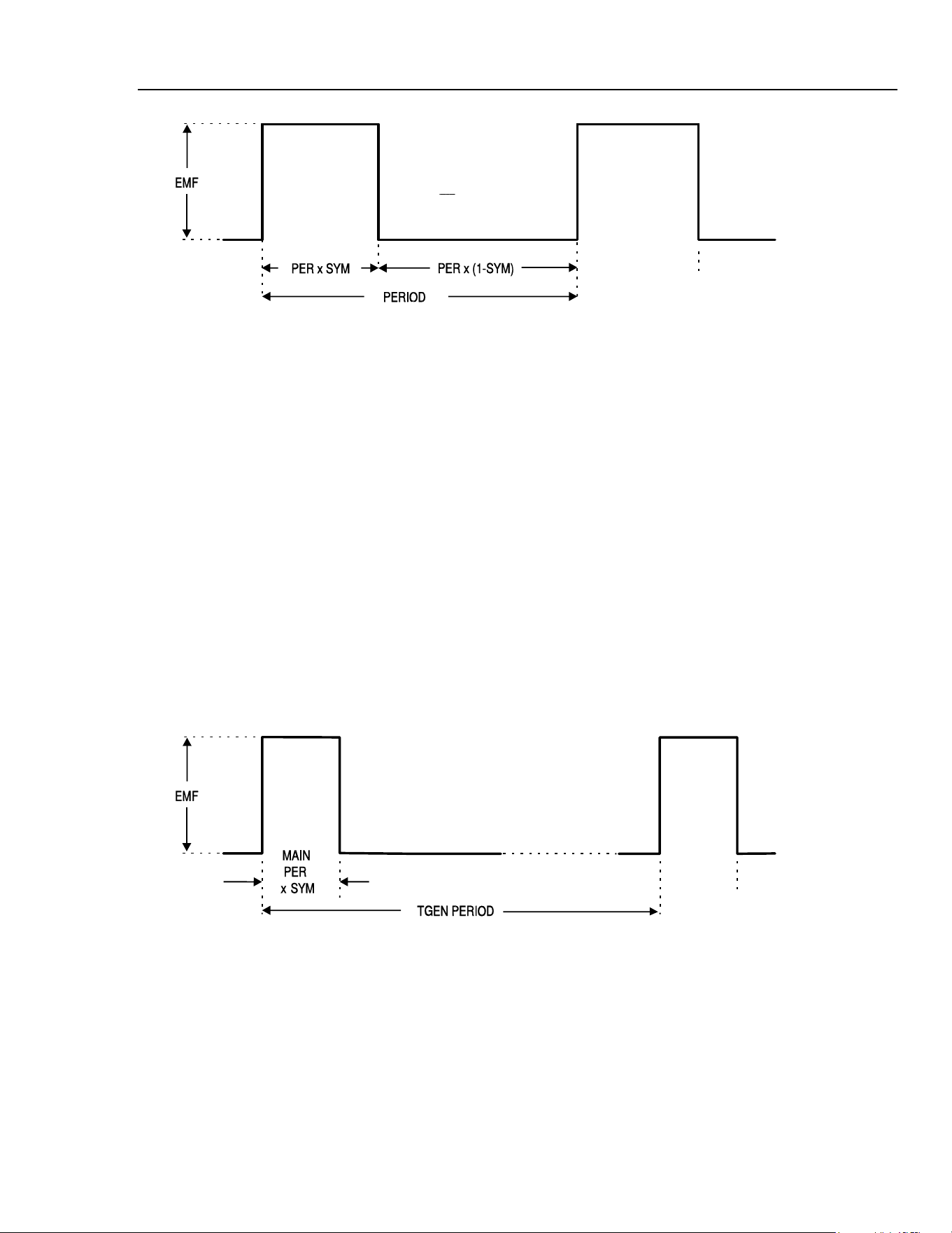
Application Examples
Low Duty Cycle Pulse Trains15
sha0011f.emf
Using this technique the duty cycle range is limited to that achievable with the symmetry
control (99:1). For very small duty cycles, at lower repetition rates, the triggering
facilities may be used, as described in the next section.
Low Duty Cycle Pulse Trains
Low duty cycle pulse trains can be created by using the internal trigger generator to
produce the long interval between the pulses, with each pulse being a single cycle of the
main generator.
Set the main generator to 10 kHz by pressing
FREQ, 1, 0, kHz, and reduce the duty-
cycle to 1:99 (i.e. pulse width of 1 µs) by pressing
SYMMETRY, 1, %.
Select the trigger menu by pressing
EDIT, TRIG, and set SOURCE=TGEN, i.e. internal
trigger generator. The
TGEN period should be at its default setting of 1.00 ms
(1.000 kHz) and the burst count set to 0001.
The default phase setting of 0 ° corresponds to the top of the rising edge of the pulse and
starting at this phase will not give the desired result; set the phase to -90 ° by moving the
cursor to the
PHASE field with the FIELD keys and enter -, 9, 0, ENTER.
Whilst still in the trigger menu press
TRIG again to turn Trigger mode on.
sha0012f.emf
A single cycle of the main generator (i.e. a single pulse) will now be output at the default
frequency of 1 kHz, so a 1000:1 duty cycle has now been achieved. Move the cursor to
the
TGEN period field with the FIELD keys and increase the period using the rotary
control; although it will be difficult to see on the oscilloscope, the 1 µs pulse width is
maintained down to milliHertz repetition rates, i.e. an extremely small duty-cycle.
Note that at main generator frequencies above 30 kHz phase control of pulse waveforms
is restricted unless waveform generation is in low frequency mode (see Waveform
generation options in chapter 5, Main Generator Operation); this ultimately limits the
minimum width of pulses at very low repetition rates.
15-3
1.888.610.7664 sales@GlobalTestSupply.com
Fluke-Direct.com
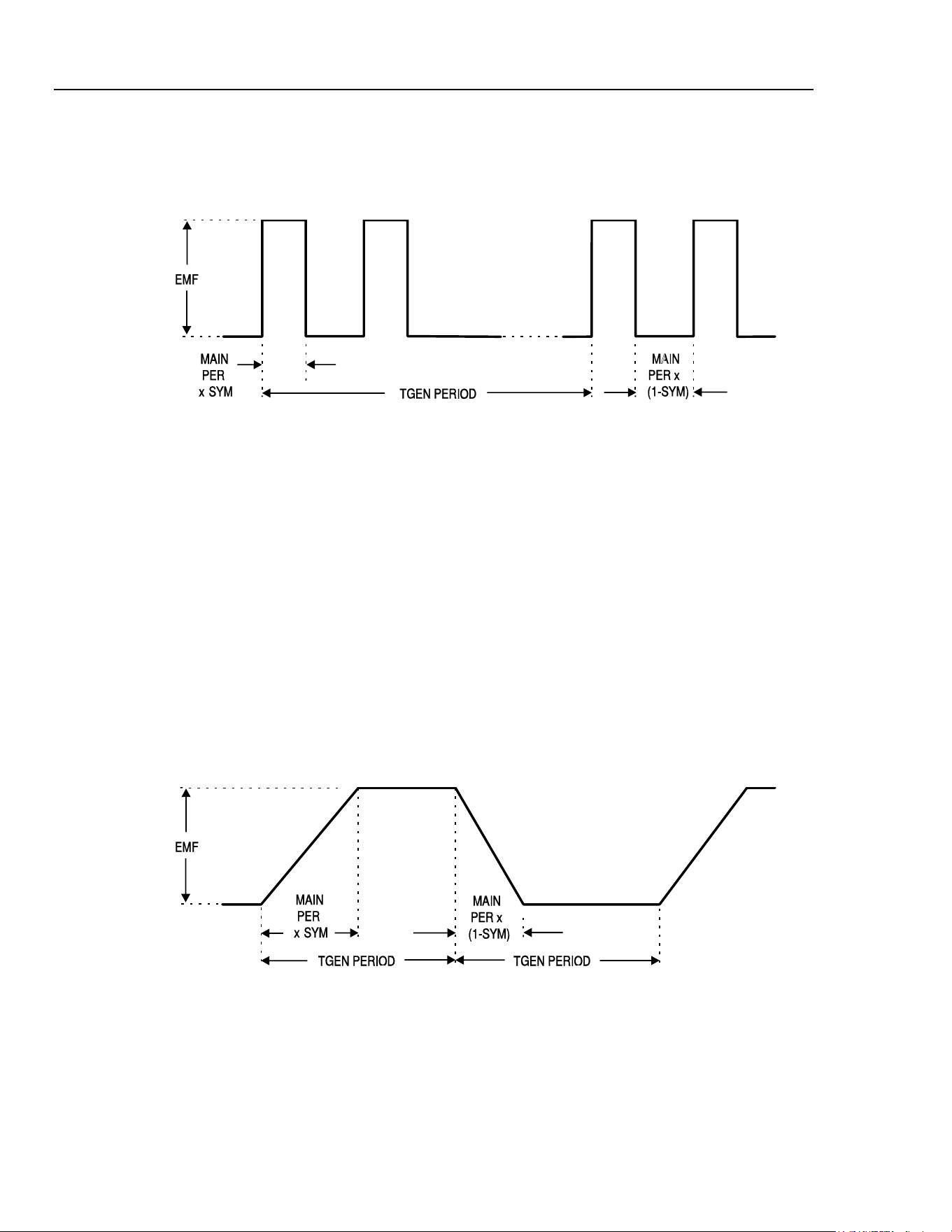
271
Users Manual
Multiple Pulses
Multiple pulse trains are obtained by using the same trigger set-up as above but with the
burst count set to the desired number of pulses.
sha0013f.emf
Set TGEN to 1.00 ms again (1 kHz) and the burst count to 2; this will give the
waveform shown. The pulse width and interval between successive pulses is determined
by the main generator frequency and symmetry; the pulse width will be
PER multiplied
by
SYM, and the pulse low time will be PER multiplied by (1-SYM). The repetition
rate of the bursts remains determined by the
TGEN period.
Variable Transition Pulse Waveforms
The half cycle triggered burst capability can be used to produce square waves with a
variety of different edge shapes. Three examples are shown, one with straight slew-
limited transitions and two with sinusoidal transitions where different start-stop phase
settings give quite different effects.
Slew-Limited Transitions
The edges of this slew rate limited pulse train are straight lines, produced by half cycles
of the main generator triangle wave. The interval between the edges is again defined by
the trigger generator.
sha0014f.emf
Set the main generator to 10 kHz, 10 V p-p, by pressing FREQ, 1, 0, kHz, and VhiZ, 1,
0, V; change the symmetry to 60:40 by pressing SYM, 6, 0, %; DC OFFSET, 0, V;
select TRIANGLE.
Select the Trigger menu by pressing EDIT, TRIG, and set SOURCE=TGEN, i.e.
internal trigger generator. Set the TGEN period to 1 ms (1.000 kHz), the
BURST COUNT t0 0.005 and the PHASE to -90°. If it is off, set trigger mode on by
pressing TRIG again.
15-4
1.888.610.7664 sales@GlobalTestSupply.com
Fluke-Direct.com

Application Examples
Variable Transition Pulse Waveforms15
The waveform should be that shown in the diagram. The rise and fall times can be
reduced by increasing the main generator frequency and the relationship between rise and
fall time can be altered by changing the symmetry.
Band-Limited Pulses
The edges of these band limited pulses are made up from sine wave segments, starting
from -90 °.
Normally the rise and fall times will be equal, so the main generator symmetry is set to
50 %.
Following on from the example above, set the symmetry and waveform using
SYMMETRY
, 5, 0, %, SINE.
If the trigger parameters have been changed from the above example, re-enter them.
sha0015f.emf
Pulses With Overshoot
Again, the edges and overshoot peaks in this waveform are made up of sine wave
segments. The amount of overshoot depends on the starting phase angle which will be
from -89 ° to about +30 °. The main generator amplitude determines the amplitude of the
peaks;. the amplitude of the flat portions depends on the
PHASE.
Following on from the previous examples, set the frequency to 20 kHz and open the
trigger menu using the key sequence
FREQ, 2, 0, kHz, EDIT, TRIG.
Move the edit cursor to the
PHASE field and use the rotary control to adjust the phase
which will vary the amplitude of the flat portion, creating variable overshoot.
sha0016f.emf
15-5
1.888.610.7664 sales@GlobalTestSupply.com
Fluke-Direct.com

271
Users Manual
15-6
1.888.610.7664 sales@GlobalTestSupply.com
Fluke-Direct.com

16-1
Chapter 16
Remote Operation
Title Page
Remote Operation.............................................................................................. 16-2
Address and Baud Rate Selection.................................................................. 16-2
Remote/Local Operation ............................................................................... 16-2
RS232 Interface............................................................................................. 16-3
Single Instrument RS232 Connections ..................................................... 16-3
Addressable RS232 Connections.............................................................. 16-3
RS232 Character Set................................................................................. 16-4
Addressable RS232 Interface Control Codes............................................ 16-4
Full List of Addressable RS232 Interface Control Codes......................... 16-6
GPIB Interface............................................................................................... 16-6
GPIB Subsets ............................................................................................ 16-6
GPIB IEEE Std. 488.2 Error Handling ..................................................... 16-6
GPIB Parallel Poll..................................................................................... 16-7
Status Reporting........................................................................................ 16-7
Standard Event Status and Standard Event Status Enable Registers......... 16-8
Status Byte Register and Service Request Enable Register ...................... 16-8
Status Model.................................................................................................. 16-9
Power on Settings...................................................................................... 16-9
Remote Commands............................................................................................ 16-10
RS232 Remote Command Formats............................................................... 16-10
GPIB Remote Command Formats................................................................. 16-10
Command List............................................................................................... 16-11
Function Selection......................................................................................... 16-12
Main Generator Parameters........................................................................... 16-12
Sweep Parameters.......................................................................................... 16-12
Trigger and Gate............................................................................................ 16-13
AM Parameters.............................................................................................. 16-13
FSK Parameters............................................................................................. 16-13
Staircase and Arbitrary Waveforms .............................................................. 16-14
Waveform Generation Options...................................................................... 16-14
Hop Commands............................................................................................. 16-14
System Commands........................................................................................ 16-15
Status Commands.......................................................................................... 16-15
Miscellaneous Commands............................................................................. 16-16
Phase Locking Commands ............................................................................ 16-16
Remote Command Summary............................................................................. 16-17
1.888.610.7664 sales@GlobalTestSupply.com
Fluke-Direct.com

271
Users Manual
16-2
Remote Operation
The following sections detail the operation of the instrument via both the GPIB and the
RS232 interfaces. Where operation is identical no distinction is made between the two.
Where differences occur these are detailed in the appropriate sections. It is therefore only
necessary to read the general sections and those sections specific to the interface of
interest.
Address and Baud Rate Selection
For successful operation, each instrument connected to the GPIB or addressable RS232
system must be assigned a unique address and, in the case of addressable RS232, all must
be set to the same Baud rate.
The instruments remote address for operation on both the RS232 and GPIB interfaces is
set via the menu accessed by pressing the
REMOTE button.
REMOTE=RS232
ADDRESS=05
BAUD RATE=9600
With the edit cursor in the
REMOTE field, the selected interface can be toggled between
RS232
and GPIB with alternate presses of the DIGIT keys, or by using the rotary
control.
The address is selected with the edit cursor in the
ADDRESS field, using the DIGIT
keys or rotary control.
Lastly the baud rate is selected with the edit cursor in the
BAUD RATE field, again
using the
DIGIT keys or rotary control.
When operating on the GPIB all device operations are performed through a single
primary address; no secondary addressing is used.
Note
GPIB address 31 is not allowed by the IEEE 488 standards but it is
possible to select it as an RS232 address.
Remote/Local Operation
At power-on the instrument will be in the local state with the
REMote lamp off. In this
state all keyboard operations are possible. When the instrument is addressed to listen and
a command is received the remote state will be entered and the
REMote lamp will be
turned on. In this state the keyboard is locked out and remote commands only will be
processed. The instrument may be returned to the local state by pressing the
EDIT key
(which doubles as the
LOCAL key); however, the effect of this action will remain only
until the instrument is addressed again or receives another character from the interface,
when the remote state will once again be entered.
1.888.610.7664 sales@GlobalTestSupply.com
Fluke-Direct.com

Remote Operation
Remote Operation16
RS232 Interface
Single Instrument RS232 Connections
The 9-way D-type serial interface connector is located on the instrument rear panel. The
pin connections are as shown below:
Pin Name Description
1
- No internal Connection
2
TXD Transmitted data from instrument
3
RXD Received data to instrument
4
- No internal connection
5
GND Signal ground
6
- No internal connection
7
RXD2 Secondary received data (see diagram)
8
TXD2 Secondary transmitted data (see diagram)
9
GND Signal ground
Pins 2, 3 and 5 may be used as a conventional RS232 interface with XON/XOFF
handshaking. Pins 7, 8 and 9 are used when the instrument is connected for addressable
RS232 operation, as described below.
Addressable RS232 Connections
Using a simple cable assembly, a daisy chain connection system between any number of
instruments up to the maximum of 32 can be made, as shown below:
INSTRUMENT
1
INSTRUMENT
2
INSTRUMENT
3
CONTROLLER
TO NEXT
INSTRUMENT
sha0017f.emf
The daisy chain consists of the transmit data (TXD), receive date (RXD) and signal
ground lines only. There are no control/handshake lines. This makes XON/XOFF
protocol essential and allows the inter-connection between instruments to contain just 3
wires.
The wiring of the adaptor cable is shown below:
16-3
1.888.610.7664 sales@GlobalTestSupply.com
Fluke-Direct.com
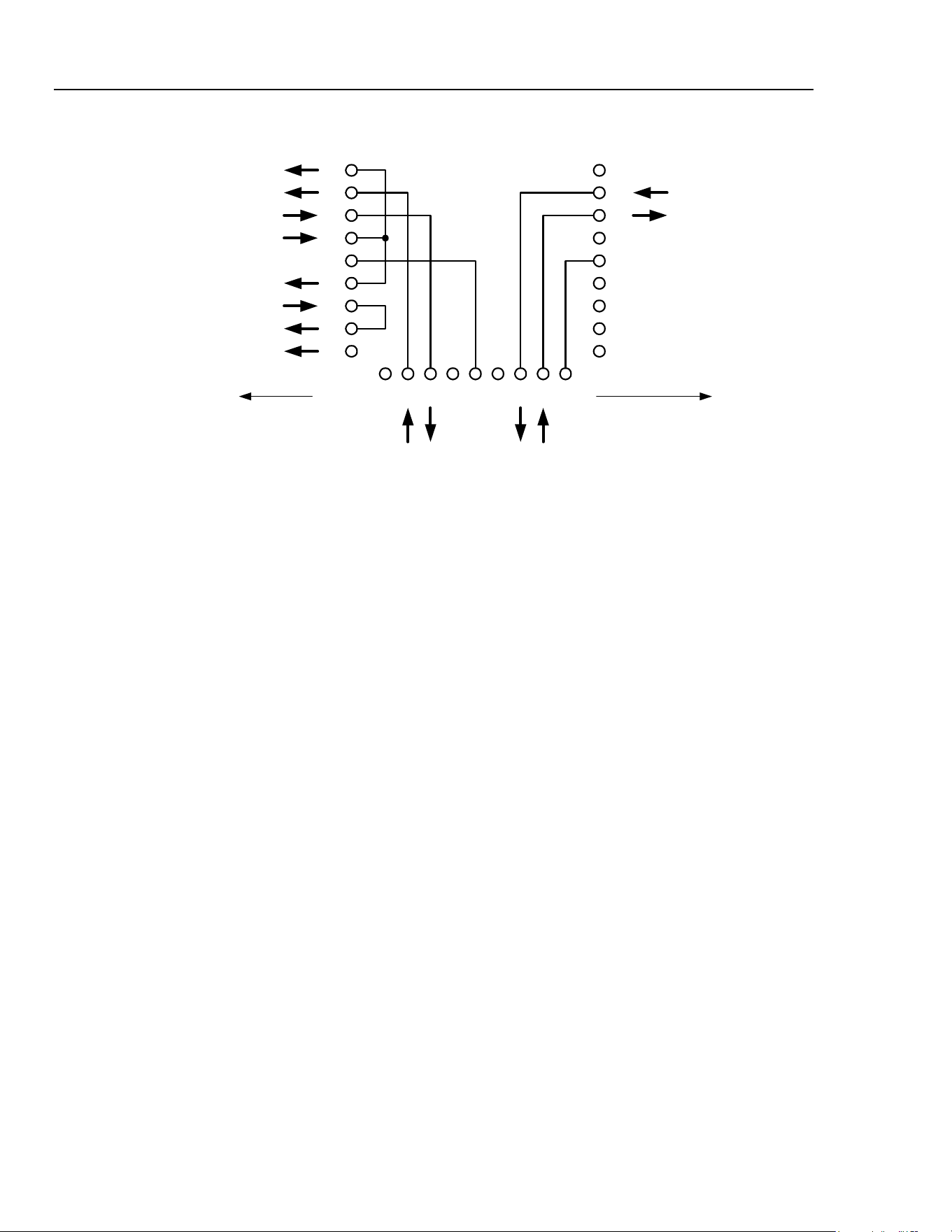
271
Users Manual
RX
1
2
3
4
5
6
7
8
9
1
2
3
4
5
6
7
8
9
DCD
RX
TX
DTR
GND
DSR
RTS
CTS
RI
TX
GND
9-WAY D
MALE
9-WAY D
FEMALE
123456789
TX RX TXIN RXOUT
UP TOWARDS
CONTROLLER
DOWN TOWARDS
OTHER INSTRUMENTS
INSTRUMENT
CONNECTOR
9-WAY D
MALE
sha0018f.emf
All instruments on the interface must be set to the same baud rate and all must be
powered on, otherwise instruments further down the daisy chain will not receive any data
or commands.
The other parameters are fixed as follows:
Start bits 1
Data bits 8
Parity None
Stop bits 1
RS232 Character Set
Because of the need for XON/XOFF handshake it is possible to send ASCII coded data
only; binary blocks are not allowed. Bit 7 of ASCII codes is ignored, i.e. assumed to be
low. No distinction is made between upper and lower case characters in command
mnemonics and they may be freely mixed. The ASCII codes below 20H (space) are
reserved for addressable RS232 interface control. In this manual 20H, etc. means 20 in
hexadecimal.
Addressable RS232 Interface Control Codes
All instruments intended for use on the addressable RS232 bus use the following set of
interface control codes. Codes between 00H and 1FH which are not listed here as having
a particular meaning are reserved for future use and will be ignored. Mixing interface
control codes inside instrument commands is not allowed except as stated below for CR
and LF codes and for XON and XOFF codes.
When an instrument is first powered on it will automatically enter the non-addressable
mode. In this mode the instrument is not addressable and will not respond to any address
commands. This allows the instrument to function as a normal RS232 controllable
device. This mode may be locked by sending the Lock Non-Addressable mode control
code, 04H. The controller and instrument can now freely use all 8 bit codes and binary
blocks but all interface control codes are ignored. To return to addressable mode the
instrument must be powered off.
16-4
1.888.610.7664 sales@GlobalTestSupply.com
Fluke-Direct.com

Remote Operation
Remote Operation16
16-5
To enable addressable mode after an instrument has been powered on the Set
Addressable Mode control code, 02H, must be sent. This will then enable all instruments
connected to the addressable RS232 bus to respond to all interface control codes. To
return to non-addressable mode the Lock Non-Addressable mode control code must be
sent which will disable addressable mode until the instruments are powered off.
Before an instrument is sent a command it must be addressed to listen by sending the
Listen Address control code, 12H, followed by a single character which has the lower 5
bits corresponding to the unique address of the required instrument. The codes A to Z or
a to z give the addresses 1 to 26 inclusive while @ is address 0 and so on. Once
addressed to listen the instrument will read and act upon any commands sent until the
listen mode is cancelled.
Because of the asynchronous nature of the interface it is necessary for the controller to be
informed that an instrument has accepted the listen address sequence and is ready to
receive commands. The controller will therefore wait for the Acknowledge code, 06H,
before sending any commands, The addressed instrument will provide this Acknowledge.
The controller should time out and try again if no Acknowledge is received within 5
seconds.
Listen mode will be cancelled if any of the following interface control codes are received:
12H
Listen Address followed by an address not belonging to this instrument.
14H
Talk Address for any instrument.
03H
Universal Unaddress control code.
04H
Lock Non-Addressable mode control code.
18H
Universal Device Clear.
Before a response can be read from an instrument it must be addressed to talk by sending
the Talk Address control code, 14H, followed by a single character which has the lower 5
bits corresponding to the unique address of the required instrument, as for the listen
address control code above. Once addressed to talk the instrument will send the response
message it has available, if any, and then exit the talk addressed state. Only one response
message will be sent each time the instrument is addressed to talk.
Talk mode will be cancelled by any of the following interface control codes being
received:
12H
Listen Address for any instrument.
14H
Talk Address followed by an address not belonging to this instrument.
03H
Universal Unaddress control code.
04H
Lock Non-Addressable mode control code.
18H Universal Device Clear.
Talk mode will also be cancelled when the instrument has completed sending a response
message or has nothing to say.
The interface code 0AH (LF) is the universal command and response terminator; it must
be the last code sent in all commands and will be the last code sent in all responses.
The interface code 0DH (CR) may be used as required to aid the formatting of
commands; it will be ignored by all instruments. Most instruments will terminate
responses with CR followed by LF.
The interface code 13H (XOFF) may be sent at any time by a listener (instrument or
controller) to suspend the output of a talker. The listener must send 11H (XON) before
the talker will resume sending. This is the only form of handshake control supported by
the addressable RS232 mode.
1.888.610.7664 sales@GlobalTestSupply.com
Fluke-Direct.com

271
Users Manual
16-6
Full List of Addressable RS232 Interface Control Codes
02H
Set Addressable Mode.
03H
Universal Unaddress control code.
04H
Lock Non-Addressable mode control code.
06H
Acknowledge that listen address received.
0AH
Line Feed (LF); used as the universal command and response terminator.
0DH
Carriage Return (CR); formatting code, otherwise ignored.
11H
Restart transmission (XON).
12H
Listen Address − must be followed by an address belonging to the required
instrument.
13H
Stop transmission (XOFF).
14H
Talk Address − must be followed by an address belonging to the required
instrument.
18H
Universal Device Clear.
GPIB Interface
The 24−way GPIB connector is located on the instrument rear panel. The pin connections
are as specified in IEEE Std. 488.1−1987 and the instrument complies with IEEE Std.
488.1−1987 and IEEE Std. 488.2−1987.
GPIB Subsets
This instrument contains the following IEEE 488.1 subsets:
Source Handshake
SH1
Acceptor Handshake
AH1
Talker
T6
Listener
L4
Service Request
SR1
Remote Local
RL1
Parallel Poll
PP1
Device Clear
DC1
Device Trigger
DT1
Controller
C0
Electrical Interface
E2
GPIB IEEE Std. 488.2 Error Handling
The IEEE 488.2
UNTERMINATED error (addressed to talk with nothing to say) is
handled as follows. If the instrument is addressed to talk and the response formatter is
inactive and the input queue is empty then the
UNTERMINATED error is generated.
This will cause the Query Error bit to be set in the Standard Event Status Register, a
value of 3 to be placed in the Query Error Register and the parser to be reset. See Status
Reporting below for further information.
The IEEE 488.2
INTERRUPTED error is handled as follows. If the response formatter
is waiting to send a response message and a
<PROGRAM MESSAGE TERMINATOR>
has been read by the parser or the input queue contains more than one
END message
then the instrument has been
INTERRUPTED and an error is generated. This will cause
the Query Error bit to be set in the Standard Event Status Register, a value of 1 to be
placed in the Query Error Register and the response formatter to be reset thus clearing the
output queue. The parser will then start parsing the next
<PROGRAM MESSAGE UNIT>
from the input queue. See Status Reporting below for further information.
1.888.610.7664 sales@GlobalTestSupply.com
Fluke-Direct.com
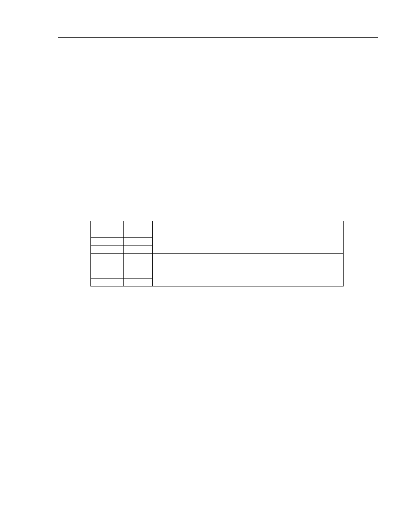
Remote Operation
Remote Operation16
16-7
The IEEE 488.2 DEADLOCK error is handled as follows. If the response formatter is
waiting to send a response message and the input queue becomes full then the instrument
enters the
DEADLOCK state and an error is generated. This will cause the Query Error
bit to be set in the Standard Event Status Register, a value of 2 to be placed in the Query
Error Register and the response formatter to be reset thus clearing the output queue. The
parser will then start parsing the next
<PROGRAM MESSAGE UNIT> from the input
queue. See Status Reporting below for further information.
GPIB Parallel Poll
Complete parallel poll capabilities are provided in this instrument. The Parallel Poll
Enable Register is set to specify which bits in the Status Byte Register are to be used to
form the
ist local message The Parallel Poll Enable Register is set by the
*
PRE
<nrf>
command and read by the
*
PRE? command. The value in the Parallel Poll
Enable Register is ANDed with the Status Byte Register; if the result is zero then the
value of
ist is 0, otherwise the value of ist is 1.
The instrument must also be configured so that the value of
ist can be returned to the
controller during a parallel poll operation. The instrument is configured by the controller
sending a Parallel Poll Configure command (
PPC) followed by a Parallel Poll Enable
command (
PPE). The bits in the PPE command are shown below:
bit 7 = x don't care
bit 6 = 1
bit 5 = 1
bit 4 = 0
parallel poll enable
bit 3 = sense sense of the response bit; 0 = low, 1 = high
bit 2 = ?
bit 1 = ?
bit 0 = ?
bit position of the response
Example: to return the
RQS bit (bit 6 of the Status Byte Register) as a 1 when true and a
0 when false in bit position 1 in response to a parallel poll operation send the following
commands:
*
PRE 64<pmt>
, then PPC followed by 69H (PPE)
The parallel poll response from the generator will then be
00H if RQS is 0 and 01H
if RQS is 1.
During parallel poll response the DIO interface lines are resistively terminated (passive
termination). This allows multiple devices to share the same response bit position in
either wired AND or wired OR configuration. Refer to the IEEE 488.1 specification for
more information.
Status Reporting
This section describes the complete status model of the instrument. Note that some
registers are specific to the GPIB section of the instrument and are of limited use in an
RS232 environment.
1.888.610.7664 sales@GlobalTestSupply.com
Fluke-Direct.com

271
Users Manual
16-8
Standard Event Status and Standard Event Status Enable Registers
These two registers are implemented as required by the IEEE standard 488.2.
Any bits set in the Standard Event Status Register which correspond to bits set in the
Standard Event Status Enable Register will cause the
ESB bit to be set in the Status
Byte Register.
The Standard Event Status Register is read and cleared by the
*
ESR? command. The
Standard Event Status Enable register is set by the
*
ESE <nrf> command and read
by the
*
ESE? command.
Bit 7 Power On. Set when power is first applied to the instrument.
Bit 6 Not used.
Bit 5 Command Error. Set when a syntax type error is detected in a command from
the bus. The parser is reset and parsing continues at the next byte in the input
stream.
Bit 4 Execution Error. Set when an error is encountered while attempting to execute
a completely parsed command. The appropriate error number will be reported
in the Execution Error Register.
Bit 3 Not used.
Bit 2 Query Error. Set when a query error occurs. The appropriate error number will
be reported in the Query Error Register as listed below.
1. INTERRUPTED error
2. DEADLOCK error
3. UNTERMINATED error
Bit 1 Not used.
Bit 0 Operation Complete. Set in response to the
*
OPC
command.
Status Byte Register and Service Request Enable Register
These two registers are implemented as required by the IEEE standard 488.2.
Any bits set in the Status Byte Register which correspond to bits set in the Service
Request Enable Register will cause the RQS/MSS bit to be set in the Status Byte
Register, thus generating a Service Request on the bus. The Status Byte Register is read
either by the
*
STB? command, which will return MSS in bit 6, or by a Serial Poll
which will return
RQS in bit 6. The Service Request Enable register is set by the
*
SRE
<nrf>
command and read by the
*
SRE? command.
Bit 7 Not used.
Bit 6 RQS/MSS This bit, as defined by IEEE Std. 488.2, contains both the
Requesting Service and Master Status Summary messages. RQS is returned in
response to a Serial Poll, MSS is returned in response to the
*
STB? command.
Bit 5 ESB The Event Status Bit. This bit is set if any bits set in the Standard Event
Status Register correspond to bits set in the Standard Event Status Enable
Register.
Bit 4 MAV The Message Available Bit. This will be set when the instrument has a
response message formatted and ready to send to the controller. The bit will be
cleared after the Response Message Terminator has been sent.
Bit 3 Not used.
Bit 2 Not used.
Bit 1 Not used.
Bit 0 Not used.
1.888.610.7664 sales@GlobalTestSupply.com
Fluke-Direct.com
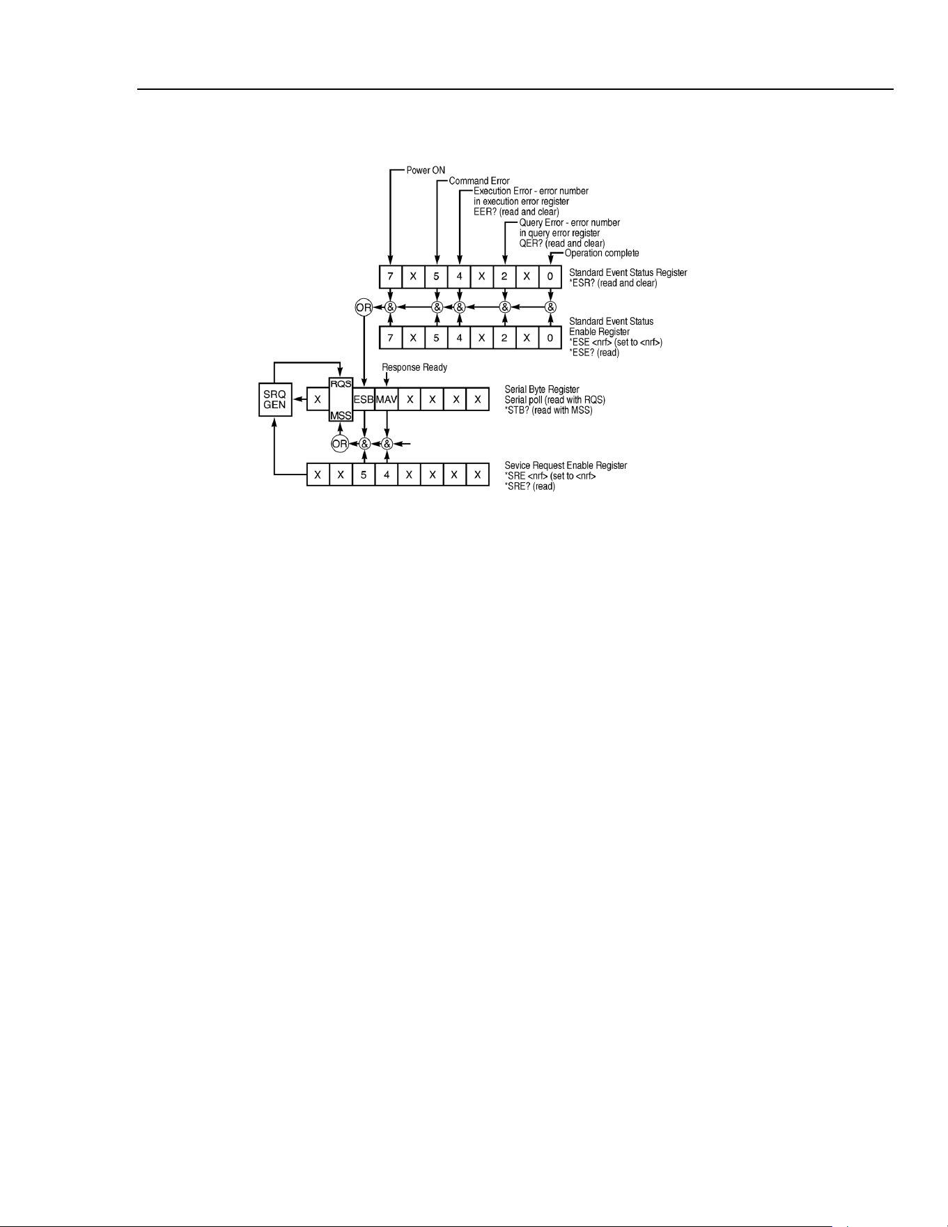
Remote Operation
Remote Operation16
Status Model
sha0020f.emf
Status model
Power on Settings
The following instrument status values are set at power on:
Status Byte Register = 0
*
Service Request Enable Register = 0
Standard Event Status Register = 128 (pon bit set)
*
Standard Event Status Enable Register = 0
Execution Error Register = 0
Query Error Register = 0
*
Parallel Poll Enable Register = 0
*
Registers marked with an asterisk are specific to the GPIB section of the instrument and
are of limited use in an RS232 environment.
The instrument will be in local state with the keyboard active.
The instrument parameters at power on are determined by the setting of the POWER UP
field on the SYStem menu, as described in the System Operations chapter. If
POWER UP=POWER DOWN or POWER UP=RECALL nn has been set and a defined
state is required by the controller at start up then the command
*
RST should be used to
load the system defaults.
If for any reason an error is detected at power up in the non-volatile ram a warning will
be issued and all settings will be returned to their default states as for a RST command.
16-9
1.888.610.7664 sales@GlobalTestSupply.com
Fluke-Direct.com

271
Users Manual
16-10
Remote Commands
RS232 Remote Command Formats
Serial input to the instrument is buffered in a 256 byte input queue which is filled, under
interrupt, in a manner transparent to all other instrument operations. The instrument will
send XOFF when approximately 200 characters are in the queue. XON will be sent
when approximately 100 free spaces become available in the queue after XOFF was
sent. This queue contains raw (not parsed) data which is taken by the parser as required.
Commands (and queries) are executed in order and the parser will not start a new
command until any previous command or query is complete. In non-addressable RS232
mode responses to commands or queries are sent immediately; there is no output queue.
In addressable mode the response formatter will wait indefinitely if necessary, until the
instrument is addressed to talk and the complete response message has been sent, before
the parser is allowed to start the next command in the input queue.
Commands must be sent as specified in the commands list and must be terminated with
the command terminator code 0AH (line feed, LF). Commands may be sent in groups
with individual commands separated from each other by the code 3BH (;). The group
must be terminated with command terminator 0AH .
Responses from the instrument to the controller are sent as specified in the commands
list. Each response is terminated by 0DH (carriage return, CR) followed by 0AH.
<WHITE SPACE> is defined as character codes 00H to 20H inclusive with the
exception of those which are specified as addressable RS232 control codes.
<WHITE SPACE> is ignored except in command identifiers; for example
*
C LS is
not equivalent to
*
CLS.
The high bit of all characters is ignored.
Commands are not case sensitive.
GPIB Remote Command Formats
GPIB input to the instrument is buffered in a 256 byte input queue which is filled, under
interrupt, in a manner transparent to all other instrument operations. The queue contains
raw (not parsed) data which is taken by the parser as required. Commands (and queries)
are executed in order and the parser will not start a new command until any previous
command or query is complete. There is no output queue which means that the response
formatter will wait, indefinitely if necessary, until the instrument is addressed to talk and
the complete response message has been sent, before the parser is allowed to start the
next command in the input queue.
Commands are sent as <PROGRAM MESSAGES> by the controller, each message
consisting of zero or more <PROGRAM MESSAGE UNIT> elements separated by
<PROGRAM MESSAGE UNIT SEPARATOR> elements.
A <PROGRAM MESSAGE UNIT> is any of the commands in the remote commands
list.
The <PROGRAM MESSAGE UNIT SEPARATOR> is the semicolon character 3BH
(;).
<PROGRAM MESSAGES> are separated by <PROGRAM MESSAGE TERMINATOR>
elements which may be any of the following:
1.888.610.7664 sales@GlobalTestSupply.com
Fluke-Direct.com

Remote Operation
Remote Commands16
16-11
NL The new line character (0AH)
NL^END The new line character with the END message
^END The END message with the last character of the message
Responses from the instrument to the controller are sent as <RESPONSE MESSAGES>.
A <RESPONSE MESSAGE> consists of one <RESPONSE MESSAGE UNIT>
followed by a <RESPONSE MESSAGE TERMINATOR>.
A <RESPONSE MESSAGE TERMINATOR> is the new line character with the END
message NL^END.
Each query produces a specific <RESPONSE MESSAGE> which is listed along with
the command in the remote commands list.
<WHITE SPACE> is ignored except in command identifiers. For example
*
C LS is
not equivalent to
*
CLS. <WHITE SPACE> is defined as character codes 00H to
20H inclusive with the exception of the NL character (0AH).
The high bit of all characters is ignored.
The commands are not case sensitive.
Command List
This section lists all commands and queries implemented in this instrument. The
commands are listed in alphabetical order within the function groups.
Note that there are no dependent parameters, coupled parameters, overlapping
commands, expression program data elements or compound command program headers;
each command is completely executed before the next command is started. All
commands are sequential and the operation complete message is generated immediately
after execution in all cases.
The following nomenclature is used:
<rmt> <RESPONSE MESSAGE TERMINATOR>
<cpd>
<CHARACTER PROGRAM DATA>, i.e. a short mnemonic or string such as ON
or OFF.
<nrf>
A number in any format. e.g. 12, 12.00, 1.2 e 1 and 120 e−1 are all accepted as
the number 12. Any number, when received, is converted to the required
precision consistent with the use then rounded up to obtain the value of the
command.
<nr1>
A number with no fractional part, i.e. an integer.
[…]
Any item(s) enclosed in these brackets are optional parameters. If more than
one item is enclosed then all or none of the items are required.
The commands in the lists below which begin with an asterisk
*
are those specified by
IEEE Std. 488.2 as Common commands. All will function when used on the RS232
interface but some are of little use.
1.888.610.7664 sales@GlobalTestSupply.com
Fluke-Direct.com

271
Users Manual
16-12
Function Selection
SINE
Set sine function
SQUARE
Set square function
TRIAN
Set triangle function
POSPUL
Set positive pulse function
NEGPUL
Set negative pulse function
POSRAMP
Set positive ramp function
NEGRAMP
Set negative ramp function
STAIR
Set staircase function
ARB
Set arbitrary function
NOISE <cpd>
Set noise <ON> or <OFF>
Main Generator Parameters
OUTPUT <cpd>
Set output <ON>, <OFF>, <NORMAL> or <INVERT>
FREQ <nrf>
Set main frequency to <nrf> Hz
PER <nrf>
Set main period to <nrf> seconds
EMFPP <nrf>
Set output level to <nrf> V p-p (open-circuit voltage)
EMFRMS <nrf>
Set output level to <nrf> V rms (open-circuit voltage)
PDPP <nrf>
Set output level to <nrf> pd V p-p
PDRMS <nrf>
Set output level to <nrf> pd V rms
DBM <nrf>
Set output level to <nrf> dBm
ZOUT <nrf>
Set output impedance to <nrf>; only 50 and 600 are legal.
DCOFFS <nrf>
Set dc offset to <nrf> Volts
SYMM <nrf>
Set symmetry to <nrf> %
PHASE <nrf>
Set phase to <nrf> degrees
Sweep Parameters
SWEEP <cpd>
Set sweep mode to <ON> or <OFF>
SWPBEGFRQ <nrf>
Set sweep begin frequency to <nrf> Hz
SWPBEGPER <nrf>
Set sweep begin period to <nrf> seconds
SWPENDFRQ <nrf>
Set sweep end frequency to
<nrf> Hz
SWPENDPER <nrf>
Set sweep end period to <nrf> seconds
SWPMKRFRQ <nrf>
Set sweep marker frequency to <nrf> Hz
SWPMKRPER <nrf>
Set sweep marker period to <nrf> seconds
SWPMODE <cpd>
Set sweep mode to <BTOE> (beginning to end) or <ETOB>
(end to beginning)
SWPLAW <cpd>
Set sweep law to <LOG> or <LIN>
SWPTIME <nrf>
Set sweep time to <nrf> seconds
1.888.610.7664 sales@GlobalTestSupply.com
Fluke-Direct.com

Remote Operation
Remote Commands16
16-13
SWPSRC <cpd>
Set sweep source to <CONT> (continuous), <EXT> (external)
or <MAN> (manual)
*
TRG
Executes a trigger which will have the same effect as pressing
the
MAN/SYNC key. MAN/REMOTE trigger source must be
selected first. GPIB Group Execute Trigger command (GET)
will perform the same function as
*
TRG.
Trigger and Gate
TRIG <cpd>
Set trigger mode to <ON> or <OFF>
GATE <cpd>
Set gate mode to <ON> or <OFF>
TRIGSRC <cpd>
Set trigger source to <EXT>, <MAN> or <TGEN>
GATESRC <cpd>
Set gate source to <EXT>, <MAN> or <TGEN>
TGEN <nrf>
Set trigger generator period to <nrf> seconds
BCNT <nrf>
Set burst count to <nrf> cycles
PHASE <nrf>
Set phase to <nrf> degrees
*
TRG
Executes a trigger which will have the same effect as pressing
the
MAN/SYNC key. MAN/REMOTE trigger source must be
selected first. GPIB Group Execute Trigger command (GET)
will perform the same function as
*
TRG.
AM Parameters
AM <cpd>
Set AM mode to <ON> or <OFF>
AMSRC <cpd>
AM source to <EXT> or <TGEN>
TGEN <nrf>
Set trigger generator period to <nrf> seconds
AMDEPTH <nrf>
Set internal AM depth to <nrf> %
AMWAVE <cpd>
Set internal AM wave to <SINE> or <SQUARE>
FSK Parameters
FSK <cpd>
Set FSK mode to <ON> or <OFF>
FSKFRQA <nrf>
Set main generator frequency to <nrf> Hz (for completeness
only)
FSKPERA <nrf>
Set main generator period to <nrf> seconds (for
completeness only)
FSKFRQB <nrf>
Set FSK frequency B to <nrf> Hz
FSKPERB <nrf>
Set FSK period B to <nrf> seconds
FSKSRC <cpd>
Set FSK source to <EXT>, <MAN> or <TGEN>
TGEN <nrf>
Set trigger generator period to <nrf> seconds
*
TRG
Executes a trigger which will have the same effect as pressing
the
MAN/SYNC key. MAN/REMOTE trigger source must be
selected first. GPIB Group Execute Trigger command (GET)
will perform the same function as
*
TRG.
1.888.610.7664 sales@GlobalTestSupply.com
Fluke-Direct.com

271
Users Manual
16-14
Staircase and Arbitrary Waveforms
STAIR
Set staircase function
SETSTAIR
<nrf>,<nrf>
Define a new staircase function. Up to 16 pairs of length and
level may be specified; valid length range 0000 to 1024, valid
level −512 to +511.
ARB
Set arbitrary function
SETARB
<nrf>,<nrf>
Define a new arbitrary function. 1024 values must be
specified to set the waveform, each one a level in the range -
512 to +511.
ARBSAV
<nrf>,<cpd>
Save arbitrary waveform to store <nrf> with name <cpd>.
The maximum length of the name is 16 characters.
N.B. If it is required to retain a waveform sent by a SETARB
command, ARBSAV must be used immediately after
SETARB. If this is not done, any other ARB operation except
ARB will destroy the data. The waveform data will also be
lost at power down unless it is saved first.
ARBRCL <nrf>
Recall arbitrary waveform from store <nrf>
ARB?
Query the selected arbitrary waveform; responds SETARB
<1024 nr1><rmt>
Waveform Generation Options
SQRWAVGEN <cpd>
Set square wave generation mode to <AUTO>,<HF> or
<LF>
FILTER <cpd>
Set filter mode to <AUTO>, <ON> or <OFF>
AUX <cpd>
Set AUX output mode to <AUTO>, <HF> or <LF>
SWPTRGOUT <cpd>
Set sweep/tgen output bnc mode to <AUTO>, <SWEEP> or
<TGEN>
Hop Commands
HOP <cpd>,<nrf>
Set hop status to <RUN> or <OFF> with last step set to
<nrf>.
SETHOP
<nrf>,<nrf>,
<nrf>,<nrf>,
<cpd>,<nrf>
Data for one step in the sequence : <step>, <time>,
<freq>, <level>, <func>, <offset>.
<step> is the step number to be defined.
<time> is the time in seconds to remain in this step. If set to
0, MANUAL will be selected. If set to le-3 EXTERNAL
will be selected.
<freq> is the main generator frequency in Hz.
<level> is the output level expressed in V p-p into an open
circuit.
<func> is any of <SINE>, <SQUARE>, <TRIAN>,
<POSPUL>, <NEGPUL>, <POSRAMP>, <NEGRAMP>,
<STAIR> or <ARB>.
<offset> is the dc offset in volts.
1.888.610.7664 sales@GlobalTestSupply.com
Fluke-Direct.com

Remote Operation
Remote Commands16
16-15
*
TRG
Executes a trigger which will have the same effect as pressing
the
MAN/SYNC key. MAN/REMOTE trigger source must be
selected first. GPIB Group Execute Trigger command (GET)
will perform the same function as
*
TRG.
System Commands
BEEPMODE <cpd>
Set beep mode to <ON>,<OFF>,<WARN> or <ERROR>
BEEP
Sound one beep.
*
RCL <nrf>
Recalls the instrument set up contained in store number
<nrf>. Valid store numbers are 0 to 9. Recalling store 0 sets
all parameters to the factory default settings.
*
RST
Resets the instrument parameters to their factory default
values.
*
SAV <nrf>
Saves the complete instrument set up in the store number
<nrf>. Valid store numbers are 1 to 9.
Status Commands
*
LRN?
Returns the complete set up of the instrument as a
hexadecimal character data block approximately 842 bytes
long. To re-install the set up the block should be returned to
the instrument exactly as it is received. The syntax of the
response is LRN <character data><rmt>.The settings
in the instrument are not affected by execution of the
*
LRN?
command.
LRN <character
data>
Install data for a previous
*
LRN? command.
EER?
Query and clear execution error number register. The
response format is <nr1><rmt>.
QER?
Query and clear query error number register. The response
format is <nr1><rmt>
*
CLS
Clear status. Clears the Standard Event Status Register, Query
Error Register and Execution Error Register. This indirectly
clears the Status Byte Register.
*
ESE <nrf>
Set the Standard Event Status Enable Register to the value of
<nrf>.
*
ESE?
Returns the value in the Standard Event Status Enable
Register in <nr1> numeric format. The syntax of the
response is <nr1><rmt>
*
ESR?
Returns the value in the Standard Event Status Register in
<nr1> numeric format. The register is then cleared. The
syntax of the response is <nr1><rmt>
*
IST?
Returns ist local message as defined by IEEE Std. 488.2.
The syntax of the response is 0<rmt>, if the local message
false or 1<rmt>, if the local message is true.
*
OPC
Sets the Operation Complete bit (bit 0) in the Standard Event
Status Register. This will happen immediately the command
is executed because of the sequential nature of all operations.
1.888.610.7664 sales@GlobalTestSupply.com
Fluke-Direct.com

271
Users Manual
16-16
*
OPC?
Query operation complete status. The syntax of the response
is 1<rmt>. The response will be available immediately the
command is executed because of the sequential nature of all
operations.
*
PRE <nrf>
Set the Parallel Poll Enable Register to the value <nrf>.
*
PRE?
Returns the value in the Parallel Poll Enable Register in
<nr1> numeric format. The syntax of the response is
<nr1><rmt>
*
SRE <nrf>
Set the Service Request Enable Register to <nrf>.
*
SRE?
Returns the value of the Service Request Enable Register in
<nr1> numeric format. The syntax of the response is
<nr1><rmt>
*
STB?
Returns the value of the Status Byte Register in <nr1>
numeric format. The syntax of the response is <nr1><rmt>
*
WAI
Wait for operation complete true. As all commands are
completely executed before the next is started this command
takes no additional action.
Miscellaneous Commands
*IDN?
Returns the instrument identification. The exact response is
determined by the instrument configuration and is of the form
<NAME>,<model>, 0, <version><rmt> where <NAME>
is the manufacturer's name, <MODEL> defines the type of
instrument and <VERSION> is the revision level of the
software installed.
*TST?
The generator has no self-test capability and the response is
always 0<rmt>
Phase Locking Commands
*TRG
Executes a trigger which will have the same effect as pressing
the
MAN/SYNC key. GPIB Group Execute Trigger
command (GET) will perform the same function as
*
TRG.
CLOCKBNC <cpd>
Set clock bnc mode to <OUTPUT>, <INPUT> or <SLAVE>
(phase lock)
ABORT
Abort on unsuccessful phase locking operation. If no
operation was in progress the command is ignored. If an
operation is aborted then error 136 is placed in the execution
error register.
1.888.610.7664 sales@GlobalTestSupply.com
Fluke-Direct.com

Remote Operation
Remote Command Summary16
16-17
Remote Command Summary
*
ESE <nrf>
Set the Standard Event Status Enable Register to the value of
<nrf>.
*
ESE?
Returns the value in the Standard Event Status Enable Register
in <nr1> numeric format.
*
ESR?
Returns the value in the Standard Event Status Register in
<nr1> numeric format.
*
IDN?
Returns the instrument identification.
*
IST?
Returns ist local message as defined by IEEE Std. 488.2.
*
LRN?
Returns the complete set up of the instrument as a
hexadecimal character data block approximately 842 bytes
long.
*
PRE <nrf>
Set the Parallel Poll Enable Register to the value <nrf>.
*
PRE?
Returns the value in the Parallel Poll Enable Register in
<nr1> numeric format.
*
RCL <nrf>
Recalls the instrument set up contained in store number
<nrf>.
*
RST
Resets the instrument parameters to their default values.
*
SAV <nrf>
Saves the complete instrument set up in the store number
<nrf>.
*
SRE <nrf>
Set the Service Request Enable Register to <nrf>.
*
SRE?
Returns the value of the Service Request Enable Register in
<nr1> numeric format.
*
STB?
Returns the value of the Status Byte Register in <nr1>
numeric format.
*
TRG
Executes a trigger which will have the same effect as pressing
the
MAN/SYNC key.
*
TST?
The generator has no self-test capability and the response is
always 0<rmt>
*
WAI
Wait for operation complete true.
ABORT
Abort on unsuccessful phase locking operation.
AM <cpd>
Set AM mode to <ON> or <OFF>
AMDEPTH <nrf>
Set internal AM depth to <nrf> %
AMSRC <cpd>
AM source to <EXT> or <TGEN>
AMWAVE <cpd>
Set internal AM wave to <SINE> or <SQUARE>
ARB
Set arbitrary function
ARB?
Query the selected arbitrary waveform.
ARBRCL <nrf>
Recall arbitrary waveform from store <nrf>
ARBSAV <nrf>,
<cpd>
Save arbitrary waveform to store <nrf> with name <cpd>.
AUX <cpd>
Set AUX output mode to <AUTO>, <HF> or <LF>
1.888.610.7664 sales@GlobalTestSupply.com
Fluke-Direct.com

271
Users Manual
16-18
BCNT <nrf>
Set burst count to <nrf> cycles
BEEP
Sound one beep.
BEEPMODE <cpd>
Set beep mode to <ON>, <OFF>, <WARN> or <ERROR>
CLOCKBNC <cpd>
Set clock bnc mode to <OUTPUT>, <INPUT> or <SLAVE>
DBM <nrf>
Set output level to <nrf> dBm
DCOFFS <nrf>
Set dc offset to <nrf> Volts
EER?
Query and clear execution error number register.
EMFPP <nrf>
Set output level to <nrf> V p-p (into an open-circuit)
EMFRMS <nrf>
Set output level to <nrf> V rms (into an open circuit)
FILTER <cpd>
Set filter mode to <AUTO>, <ON> or <OFF>
FREQ <nrf>
Set main frequency to <nrf> Hz
FSK <cpd>
Set FSK mode to <ON> or <OFF>
FSKFRQA <nrf>
Set main generator frequency to <nrf> Hz (for completeness
only)
FSKFRQB <nrf>
Set FSK frequency B to <nrf> Hz
FSKPERA <nrf>
Set main generator period to <nrf> seconds (for
completeness only)
FSKPERB <nrf>
Set FSK period B to <nrf> seconds
FSKSRC <cpd>
Set FSK source to <EXT>, <MAN> or <TGEN>
GATE <cpd>
Set gate mode to <ON> or <OFF>
GATESRC <cpd>
Set gate source to <EXT>, <MAN> or <TGEN>
HOP <cpd>,<nrf>
Set hop status to <RUN> or <OFF> with last step set to
<nrf>.
LRN <character
data>
Install data from a previous
*
LRN? command.
NEGPUL
Set negative pulse function
NEGRAMP
Set negative ramp function
NOISE <cpd>
Set noise <ON> or <OFF>
OUTPUT <cpd>
Set output <ON>, <OFF>, <NORMAL> or <INVERT>
PDPP <nrf>
Set output level to <nrf> pd V p-p
PDRMS <nrf>
Set output level to <nrf> pd V rms
PER <nrf>
Set main period to <nrf> seconds
PHASE <nrf>
Set phase to <nrf> degrees
POSPUL
Set positive pulse function
POSRAMP
Set positive ramp function
SETARB
<nrf>,...<nrf>
Define a new arbitrary function.
1.888.610.7664 sales@GlobalTestSupply.com
Fluke-Direct.com

Remote Operation
Remote Command Summary16
16-19
SETHOP
<nrf>,<nrf>,
<nrf>,<nrf>,
<cpd>,<nrf>
Data for one step in the sequence .
SETSTAIR
<nrf>,...<nrf>
Define a new staircase function.
SINE
Set sine function
SQRWAVGEN <cpd>
Set square wave generation mode to <AUTO>, <HF> or <LF>
SQUARE
Set square function
STAIR
Set staircase function
SWEEP <cpd>
Set sweep mode to <ON> or <OFF>
SWPBEGFRQ <nrf>
Set sweep begin frequency to <nrf> Hz
SWPBEGPER <nrf>
Set sweep begin period to <nrf> seconds
SWPENDFRQ <nrf>
Set sweep end frequency to <nrf> Hz
SWPENDPER <nrf>
Set sweep end period to <nrf> seconds
SWPLAW <cpd>
Set sweep law to <LOG> or <LIN>
SWPMKRFRQ <nrf>
Set sweep marker frequency to <nrf> Hz
SWPMKRPER <nrf>
Set sweep marker period to <nrf> seconds
SWPMODE <cpd>
Set sweep mode to <BTOE> (beginning to end) or <ETOB>
(end to beginning)
SWPSRC <cpd>
Set sweep source to <CONT> (continuous), <EXT> (external)
or <MAN> (manual)
SWPTIME <nrf>
Set sweep time to <nrf> seconds
SWPTRGOUT <cpd>
Set sweep/tgen output bnc mode to <AUTO>, <SWEEP> or
<TGEN>
SYMM <nrf>
Set symmetry to <nrf> %
TGEN <nrf>
Set trigger generator period to <nrf> seconds
TRIAN
Set triangle function
TRIG <cpd>
Set trigger mode to <ON> or <OFF>
TRIGSRC <cpd>
Set trigger source to <EXT>, <MAN> or <TGEN>
ZOUT <nrf>
Set output impedance to <nrf>; only 50 and 600 are legal.
1.888.610.7664 sales@GlobalTestSupply.com
Fluke-Direct.com

271
Users Manual
16-20
1.888.610.7664 sales@GlobalTestSupply.com
Fluke-Direct.com

Appendices
Appendix Title Page
A AC Supply Voltage Settings ............................................................................... A-1
B DDS Operation and Further Waveform Considerations ..................................... B-1
C Application Information Notes............................................................................ C-1
D Warning and Error Messages .............................................................................. D-1
E Factory System Defaults ..................................................................................... E-1
F Waveform Manager Plus..................................................................................... F-1
G Front and Rear Panels ......................................................................................... G-1
1.888.610.7664 sales@GlobalTestSupply.com
Fluke-Direct.com

271
Users Manual
-2
1.888.610.7664 sales@GlobalTestSupply.com
Fluke-Direct.com

Appendix A
AC Supply Voltage Settings
Introduction
Before use, check that the instrument operating voltage marked on the rear panel is
suitable for the local supply.
Warning
To avoid the possibility of electric shock, always ensure the
instrument is disconnected from the ac supply before opening
the case.
Should it be necessary to change the operating voltage, proceed as follows:
1. Disconnect the instrument from all voltage sources.
2. Remove the screws which retain the top cover and lift off the cover.
3. Change the transformer connections as follows:
for 230V operation connect the live (brown) wire to pin 15
for 115V operation connect the live (brown) wire to pin 14
for 100V operation connect the live (brown) wire to pin 13
4. Refit the cover and the secure with the same screws.
5. Change the fuse to one of the correct rating, see below.
Caution
To comply with safety standard requirements the operating
voltage marked on the rear panel must be changed to clearly
show the new voltage setting.
A-1
1.888.610.7664 sales@GlobalTestSupply.com
Fluke-Direct.com
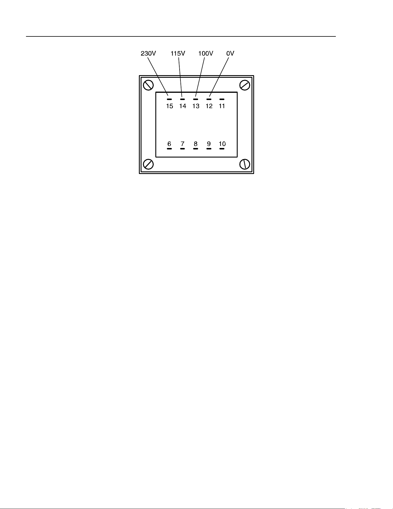
271
Users Manual
sha0021f.emf
Mains transformer connections
Fuse
Ensure that the correct mains fuse is fitted for the set operating voltage. The correct
mains fuse types are:
for 230V operation: 250 mA (T) 250 V HRC
for 100V or 115V operation: 500 mA (T) 250 V HRC
To replace the fuse, disconnect the mains lead from the inlet socket and withdraw the
fuse drawer below the socket pins. Change the fuse and replace the drawer.
The use of makeshift fuses or the short-circuiting of the fuse holder is prohibited.
A-2
1.888.610.7664 sales@GlobalTestSupply.com
Fluke-Direct.com
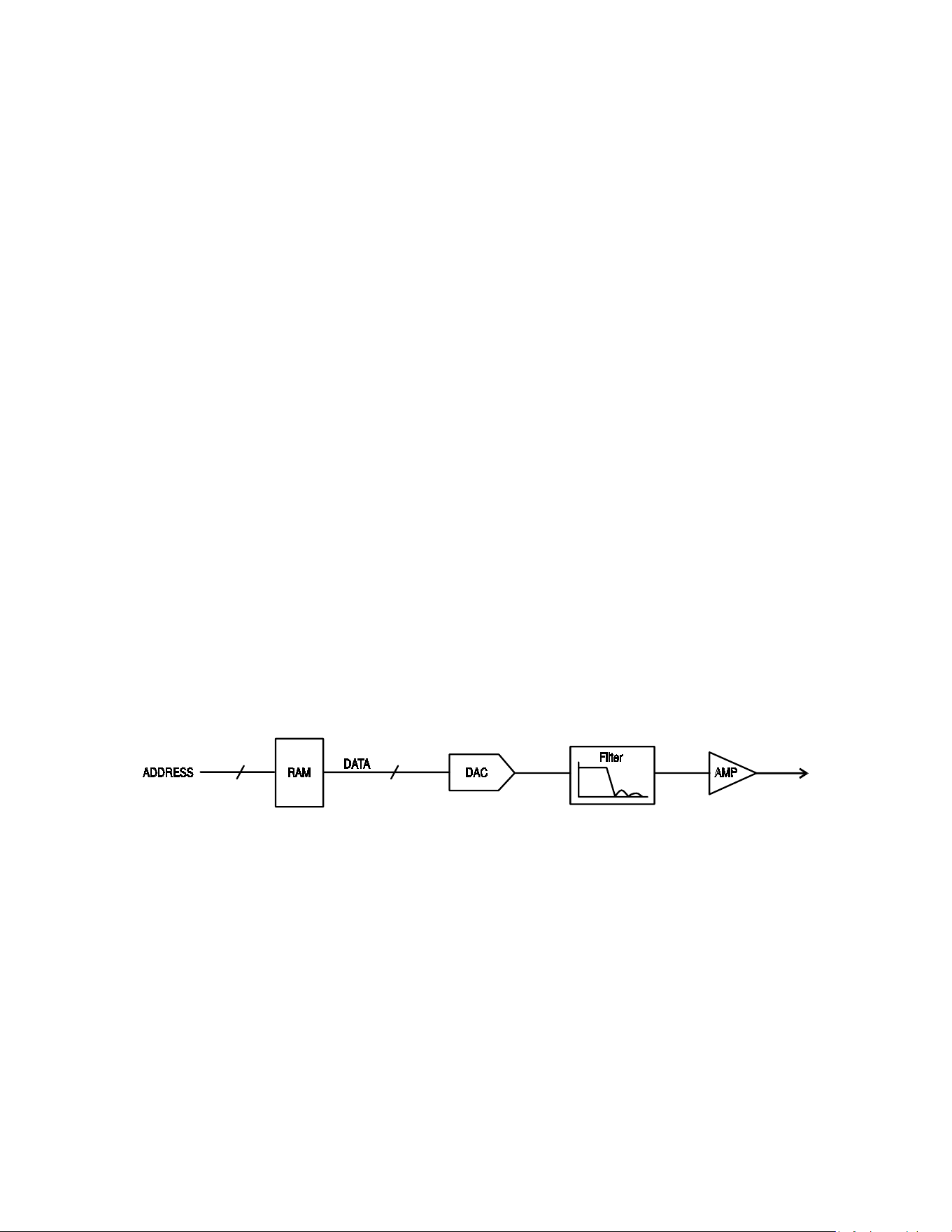
Appendix B
DDS Operation and Further Waveform
Considerations
Introduction
This appendix gives some further information on DDS operation as a background to
understanding both the advantages and the limitations of DDS waveform generation.
DDS Operation
10 Bit10 Bit
sha0022f.emf
One complete cycle of the selected waveform is stored in RAM as 1024 10-bit amplitude
values. As the RAM address is incremented the waveform values are output sequentially
to a digital-to-analogue converter (DAC) which reconstructs the waveform as a series of
voltage steps. Sine waves and triangle waves are subsequently filtered to smooth the steps
in the DAC output.
The frequency of the output waveform is determined by the rate at which the RAM
addresses are changed; in a DDS system the address changes are generated as follows.
The RAM contains the amplitude values of all the individual points of 1 cycle (360 °) of
the waveform; each sequential address change corresponds to a phase increment of the
waveform of 360 ° divided by 1024. Instead of using a counter to generate sequential
RAM addresses, a phase accumulator is used to increment the phase.
B-1
1.888.610.7664 sales@GlobalTestSupply.com
Fluke-Direct.com
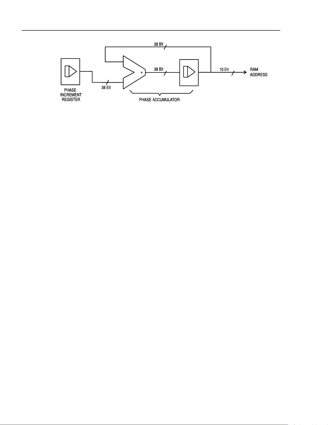
271
Users Manual
sha0023f.emf
On each clock cycle the phase increment, which has been loaded into the phase increment
register by the CPU, is added to the current result in the phase accumulator; the 10 most
significant bits of the phase accumulator drive the RAM address lines. The output
waveform frequency is now determined by the size of the phase increment at each clock.
If each increment is the same size then the output frequency is constant; if it changes, the
output frequency changes but with phase continuity.
The generator uses a 38-bit accumulator and a clock frequency which is 2
38
x 10
-4
(approximately 27.487 MHz); this yields a frequency resolution (corresponding to the
smallest phase increment) of f
CLK
/2
38
= 0.1 mHz.
Only the 10 most significant bits of the phase accumulator are used to address the RAM.
At a waveform frequency of f
CLK
/1024 (approximately 26.84 kHz), the ‘natural’
frequency, the RAM address increments on every clock. At all frequencies below this
(i.e. at smaller phase increments) one or more addresses are output for more than one
clock period because the phase increment is not big enough to step the address at every
clock. Similarly at waveform frequencies above the natural frequency the larger phase
increment causes some addresses to be skipped, giving the effect of the stored waveform
being ‘sampled’; different points will be sampled on successive cycles of the waveform.
The minimum number of points required to reproduce a wave shape accurately will
determine the maximum useful output frequency:
f
MAX
= f
CLK
/(number of points)
For sine waves the filter permits the waveform to be reproduced accurately up to the
Nyquist limit (f
CLK
/2), although in this generator a practical limit of 10 MHz is set.
B-2
1.888.610.7664 sales@GlobalTestSupply.com
Fluke-Direct.com
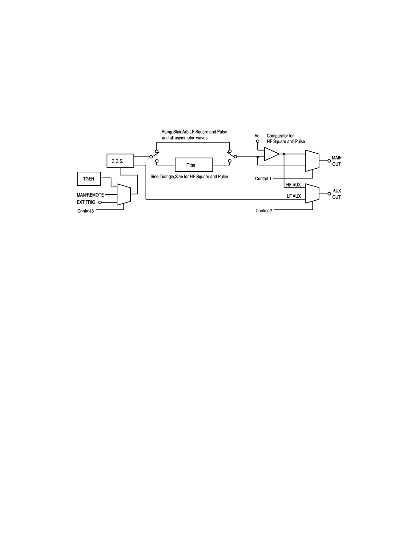
Appendices
DDS Operation and Further Waveform Considerations B
Further Waveform Considerations
The various limitations on combinations of modes, most of which have already been
mentioned in the appropriate operational sections of the manual, are brought together
here and explained with reference to the simplified block diagram below.
Simplified Generator Block Diagram
sha0024f.emf
The diagram shows simplified paths for the main and auxiliary outputs. LF and HF refer
to the low frequency and high frequency modes set for square wave and pulses and for
the auxiliary output in the
SQWAVE GEN= and AUX= fields of the options menu, as
described in the Waveform Generation Options section of chapter 5, Main Generator
Operation. When these fields are set to
AUTO the modes automatically change from LF
to HF above 30 kHz, but they can be overridden and setting to LF or HF will set that
generating mode whatever the generator frequency.
Similarly, when set to
AUTO on the options menu, the filter will be switched in or out
depending on waveform as shown; again this can be overridden and setting the filter ON
or OFF will override this so that all or none (respectively) of the waveforms will be
filtered.
Interaction of Various Option Settings
Important points to consider when setting the option menu fields to anything other than
AUTO are as follows:
1. The comparator which generates HF square waves and pulses for the
MAIN OUT
socket is driven, by default, by a filtered sine wave. If the filter is set OFF, the
waveform driving the comparator will be degraded, leading to degradation of the HF
square wave, pulse etc.
2. The same comparator is used to derive the signals for the
AUX OUT socket; the
waveform driving the comparator depends on the main waveform selection. For HF
square wave and pulse
MAIN OUT signals the driving waveform is a filtered sine
wave as described above; for sine wave and triangle MAIN OUT signals the
comparator drive is the waveform itself (also filtered). The main waveform also
drives the comparator for ramp, staircase and arbitrary waveforms plus LF square
waves and pulses, all of which are unfiltered; this means that if the
MAIN OUT
waveform shows edge jitter as the frequency increases, so will the HF AUX OUT.
For this reason, the default (AUTO) setting for the auxiliary output is LF mode at all
frequencies for main waveforms of ramp, staircase, arbitrary and LF square waves
and pulses.
B-3
1.888.610.7664 sales@GlobalTestSupply.com
Fluke-Direct.com

271
Users Manual
B-4
3. By default, ramp, staircase, arbitrary and all waveforms whose symmetry is set to
other than 50% are unfiltered. It may be desirable to force the filter
ON under some
circumstances to improve waveform quality, e.g. for higher frequency sine waves
that are only slightly asymmetric.
4. Similarly asymmetric HF square waves, pulses and auxiliary outputs generated from
the comparator will be improved if the filter is forced
ON to filter the signal driving
the comparator.
5. When staircase, arbitrary or LF mode square waves or pulses are selected the
comparator is driven by the unfiltered main waveform. With all except square waves
it is possible to have a wave shape which never crosses the comparator threshold,
thus the HF auxiliary output may be permanently high or low. To avoid this situation,
the default (
AUTO) AUX setting is LF mode; however, in this mode edge jitter will
become increasingly significant at higher frequencies.
6. Phase shift between the
MAIN OUT and AUX OUT sockets at higher frequencies
(only possible by setting AUX to LF mode) will be different for those signals which
are unfiltered compared to those which, by default, have the filter in the signal path.
For example, HF square waves and pulses from the comparator will be further phase
shifted compared to LF mode square waves of the same frequency because the sine
wave driving the comparator is significantly delayed by the filter.
7. Setting square waves or pulses to LF mode at higher frequencies will also introduce
an uncertainty of one clock edge at the
AUX OUT socket, even if this is still set to
AUTO or HF, because the comparator is now being driven by an LF mode waveform
instead of the filtered sine wave.
Frequency Modes for Sweep and FSK
For sweep and FSK operation the
MAIN OUT and AUX OUT waveform modes are
fixed
HF or LF even if the setting on the option menu is AUTO. The setting under
these circumstances is that of the main generator before either sweep or FSK was turned
on. For example, if the two FSK frequencies are 25 kHz and 50 kHz and the main
generator frequency before FSK was turned on was 25 kHz, FSK waveforms will be
generated in LF mode. In both cases however, the automatic choice can be overridden by
selecting
HF or LF instead of AUTO in the SQWAVE GEN= and AUX= fields of
the options menu.
Phase-shifted Asymmetric Waveforms
The interaction of symmetry adjustment and start/stop phase of triggered bursts gives
waveforms which are difficult to anticipate. In principle, adjusting the symmetry moves
the 180 ° phase point from the 50:50 position of 50 % symmetry to, for example, the
40:60 point of 40 % symmetry. The 0 ° to 180 ° points are now mathematically scaled
down to fit into the first 40 % of the cycle and the 180 ° to 360 ° points are scaled up to
fit into the remaining 60% of the cycle. Start/stop phase still works with the true phase
settings but they are not necessarily at the expected point on the waveform, particularly
for more complex wave shapes.
1.888.610.7664 sales@GlobalTestSupply.com
Fluke-Direct.com

Appendix C
Application Information Notes
Note 1: Special Considerations for Slow and Narrow Sweeps
When using narrow frequency sweeps in combination with long ramp times it is possible
that the magnitude of the frequency increment can become so small with respect to the
magnitude of the sweep start frequency that the internal mathematical precision of the
TG1010 is exceeded. As the ramp time is increased for a given frequency span there is a
progressive loss of accuracy of the calculated sweep stop frequency until a point is
reached where a linear sweep will not function at all and a log sweep will reverse in
direction.
The points at which these effects occur depend on the numerical values involved and
cannot be defined precisely, but the following serves as a guide.
if F
INC
<
6
START
10
F
stop frequency accuracy will be affected.
if F
INC
<
7
START
10
F
the sweep may not function at all.
In the above, F
START
and F
STOP
are the actual frequencies of sweep start and stop; F
START
will be
BEG FREQ if MODE is BEG-END, F
START
will be END FREQ if MODE is
END-BEG
, etc.
F
INC
is calculated as follows:
For linear sweeps
=
INC
F
(
)
RAMPTIME
STARTSTOP
tFF
×
−
For log sweeps
=
INC
F
(
)
START
STOP
RAMPTIME
t
F
F
⎟
⎠
⎞
⎜
⎝
⎛
where t = 5e
-3
(5 ms) for ramp times above 200 ms,
C-1
1.888.610.7664 sales@GlobalTestSupply.com
Fluke-Direct.com

271
Users Manual
C-2
t = 1.25e
-4
(125 µs) for ramp times up to 200 ms.
Note 2: Phase Error and Phase Jitter
Main Out to Aux Out
The level of phase error or jitter depends on frequency and function. Below 30 kHz the
two outputs are generated in the same way and any jitter is due only to delays and/or
phase shifts in the paths taken by the signals to reach the BNC outputs. As these delays or
phase shifts are constant the jitter results only from the 27 MHz crystal oscillator and is
typically less than -110 dBc/Hz at 10 kHz offset from the carrier.
Above 30 kHz (and becoming more significant as the frequency rises) three things must
be taken into account:
1. The phase is fixed at 0 ° unless the
AUX= field on the options menu is set to
LOFRQ
.
2. The block diagram and explanation in appendix B show the changes in paths of the
signals as the user makes changes to the various settings. The path changes cause
variations in the absolute value of the phase angle and path variations with frequency
and waveform cause absolute and/or jitter variation in phase. For example with a sine
wave at 1 MHz the delay through the filter is much longer than that at 50 kHz so the
phase error will be greater at 1 MHz than at 50 kHz if LF AUX is used. Using HF
AUX the errors will be much smaller (but fixed at 0 °).
3. Above 30 kHz the DDS waveform generation begins to down-sample the data stored
in RAM, which means that not every point is played back on every cycle. Consider a
one cycle square wave in RAM, which consists of 512 points low followed by 512
points high. At low frequency all points are sampled for every cycle of the waveform
but as the frequency rises above 30 kHz some points get missed. If either of the two
points which define the edge of the square wave are missed then the edge will shift in
time. However, due to the apparently random sampling phase, which changes every
cycle, the points are not always missed in the same way so the edge appears to move
on a cycle by cycle basis, i.e. it jitters. The total jitter from one cycle to the next is
never more than one 27 MHz clock period (36 ns) which at 50 kHz represents 0.65 °
of phase jitter but at 5 MHz the jitter is 65 °. This may be demonstrated by setting
SQWAVE GEN=LO FREQ on the options menu and observing a square wave at the
two frequencies on an oscilloscope. The above will apply to the
AUX OUT square
wave above 30 kHz when
AUX=LOFRQ is selected on the options menu. If this is
combined with a main output square wave generated with
SQWAVEGEN=AUTO on
the options menu then the phase jitter will become very large at high frequencies.
The above gives a brief outline of phase variation and jitter under different conditions,
but it should be remembered that the best phase accuracy is only 360 °/1024 or 0.35 °,
there being at best only 1024 points each cycle of the waveform.
Between Phase-locked Generators
When phase locking two generators all the above factors must be considered in case they
have an effect on the result. In general, however, when two generators are used to
generate the same waveform at the same frequency with some phase shift and the outputs
are taken from the main outputs of the two generators, then the phase accuracy will be
better than 0.5 ° and the jitter will be determined by the crystal oscillator in the master
generator. Take care to keep the clock and synchronization cables short and of good
quality.
1.888.610.7664 sales@GlobalTestSupply.com
Fluke-Direct.com

D-1
Appendix D
Warning and Error Messages
Introduction
Warning messages are given when a setting may not give the expected result. For
example, when the dc offset is affected by a change in the setting of the stepped output
attenuator. In these cases the new setting is implemented.
Error messages are given when an illegal setting is attempted. In these cases the previous
setting is retained.
The two most recent warning or error messages can be reviewed by pressing
EDIT
followed by MSG (the numeric 0 key). The later of the two is reported first.
Warning and error messages are reported with a number on the display; only the number
is reported via the remote control interfaces.
The following is a complete list of messages as they appear on the screen. In most cases
they are self-explanatory but where doubt may arise some further explanation is given.
Warning Messages
00 No errors or Warns have been reported.
07 DC Offset change by Output level
09 Symmetry too wide for func/freq
10 Symmetry changed by function/freq
11 DC Offset atten by Output level
14 Trigger Generator max res 20us
17 Phase angle change by function/freq
20 This instrument is not calibrated
1.888.610.7664 sales@GlobalTestSupply.com
Fluke-Direct.com

271
Users Manual
D-2
22
Operation is illegal here.
This warning is used when certain key entries are attempted during operations
where they are not permitted. Such operations include:
The instrument is a synchronous slave
Edit modes of STAIR and ARB
Hop mode selected
Noise selected
Full explanations of the restrictions will be found in the appropriate operational
sections of this manual.
23 Mode illegal when synchronous slave
24 Burst time exceeds TGEN period
25 DC Offset + level may cause clipping
Error Messages
101 Frequency/Period Val out of range
102 Max Output level exceeded
103 Min Output level exceeded
104 Requested units are illegal here
105 Min DC Offset exceeded
106 Max DC Offset exceeded
108 Symmetry value is illegal
112 Trigger generator period too big
113 Trigger generator period too small
115 Burst count value out of range
116 Phase angle value out of range
118 Trigger generator fixed by am sine
119 Mod depth value out of range
121 System ram error battery flat?
126 Sweep time is too long
127 Sweep time is too short
128 No GPIB interface is available
134 Illegal HOP step number requested
135 HOP time value out of range
136 Unable to phase lock to master
Error Messages - Remote Control Only
The following messages are only relevant to remote control operation.
129 Illegal store number requested
130 Byte value outside the range 0 to 255
131 Illegal value in staircase data
132 Illegal ARB store
133 Illegal value in arbitrary data
1.888.610.7664 sales@GlobalTestSupply.com
Fluke-Direct.com

E-1
Appendix E
Factory System Defaults
Introduction
The factory system defaults are listed in full below. They can be recalled by pressing
RECALL
, 0, ENTER or by the remote command *RST.
Main menu parameters
Frequency: 10 kHz
Output: 20 V p-p and output
OFF
Zout: 50 Ω
DC offset: 0 V
Symmetry: 50 %
Trigger parameters
Source:
EXT
TGEN: 1 ms
Burst count: 1
Phase: 0 °
Gate parameters
Source:
EXT
TGEN 1 ms
FSK parameters
Freq A 10 kHz
Freq B 10 MHz
Source
EXT
TGEN 1 ms
1.888.610.7664 sales@GlobalTestSupply.com
Fluke-Direct.com

271
Users Manual
E-2
AM parameters
Source:
EXT VCA
TGEN: 1 ms
Internal Mod Depth: 30 %
Internal Mod Wave: Square
Stair parameters
Symmetrical 3-level square wave, maximum amplitude.
ARB parameters
Default waveform from store 14, i.e. sin(x)/x.
Sweep parameters
Begin frequency: 100 kHz
End frequency: 10 MHz
Marker frequency: 5 MHz
Mode: Beginning to end
Law: Log
Ramp time: 50 ms
Trig Source: Continuous
Noise
Noise
OFF
Hop parameters
Hop
OFF
All parameters are unaffected by
RECALL 0 or *RST except Last Step which is set to
01.
1.888.610.7664 sales@GlobalTestSupply.com
Fluke-Direct.com

F-1
Appendix F
Waveform Manager Plus
Arbitrary Waveform Creation and Management Software
The Waveform Manager Plus program allows construction, editing, exchange, translation
and storage of many types of waveform data. It is compatible with many popular DSOs
and waveform generation products.
Waveforms may be generated by equation entry, freehand drawing, combining existing
waveforms or any combinations of these methods.
Data upload and download are possible via RS232 (COM1-4) or GPIB subject to a
compatible GPIB card being correctly installed and configured in your PC.
Both upload and download of waveform data are possible and, where applicable, data
exchange via 3.5 in floppy disks in the Tektronix *.ISF format is available.
Text data may be read from the Windows clipboard and used to create a waveform. The
text data format is very free and will allow most lists of numbers, with or without
intervening text, to be read as waveform data points. Waveform data may also be pasted
to the clipboard for insertion into other programs.
Waveforms are displayed in fully scaleable windows and may be manipulated
graphically. Any number of waveforms in any of the supported types may be displayed
simultaneously.
On-line help is available in three ways.
1. The help menu contains a contents option from which you can go to any section of
the on-line help file or browse particular areas or the whole file. It is also possible to
use the Index and Find operations of the Windows help system to search for items
which are not listed directly in the contents section.
2. Some dialog boxes have a Help button which, when clicked, will open the on-line
help file at the section containing the description of that dialog box.
3. From most windows and dialogues the F1 key will open the help file at the relevant
section.
1.888.610.7664 sales@GlobalTestSupply.com
Fluke-Direct.com

271
Users Manual
F-2
Waveform Manager allows you to keep waveforms for different projects separate from
each other on your hard drive. A project may be placed anywhere, in any directory
(folder) and all waveform files for that project will be stored in a structure below that
directory. A project is identified by a user defined name. Each project maintains its own
library of expressions.
1.888.610.7664 sales@GlobalTestSupply.com
Fluke-Direct.com
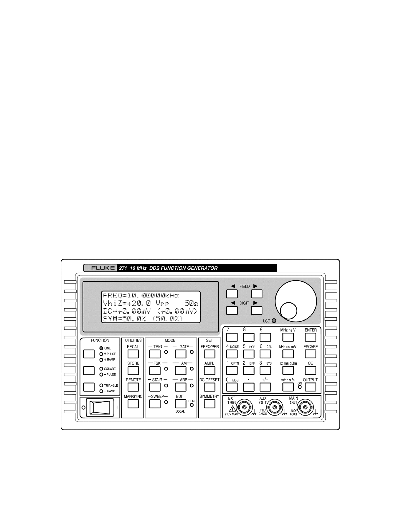
Appendix G
Front and Rear Panels
Front panel
sha0025f.gif
G-1
1.888.610.7664 sales@GlobalTestSupply.com
Fluke-Direct.com
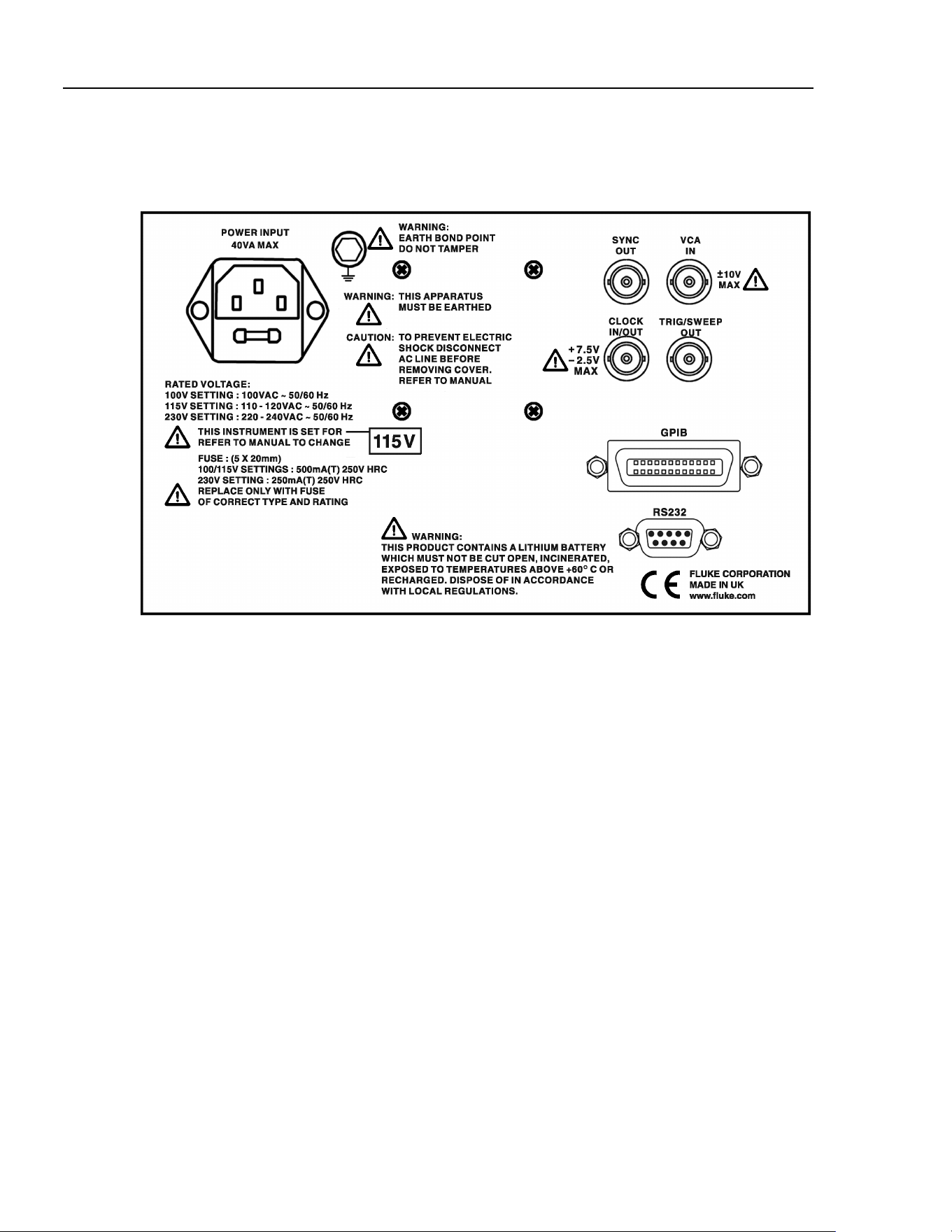
271
Users Manual
Rear panel
sha0027f.gif
G-2
1.888.610.7664 sales@GlobalTestSupply.com
Fluke-Direct.com

1
Index
—A—
ac supply voltage, 2-2, A-1
address
remote, 16-2
adressable mode, 16-4
arbitrary
store/recall, 10-3
arbitrary waveform, 10-3
ARC interface, 16-3
attenuator, 5-4
auto settings, 5-9
auxiliary output, 3-2, 5-7, 5-10
—B—
block diagram, B-3
burst count, 7-3
—C—
calibration, 14-2
routine, 14-3
clock in/out, 3-2
commands
remote, 16-11, 16-17
connections
sweep, 6-2
synchronization, 13-2
connector
clock in/out, 12-2
external trigger, 7-2
front panel, 3-2
GPIB, 3-4
rear panel, 3-2
RS232, 3-4
contrast
display, 4-3
control codes
remote, 16-5
controls, 4-3
frequency, 5-2
period, 5-2
rotary, 4-3, 4-4, 12-2
crystal
master clock, 14-2
cursor style, 12-2
—D—
daisy chain, 13-2, 16-3
dc offset, 5-4
defaults, E-1
digit keys, 4-4
direct digital synthesis (DDS), 1-2, B-1
principles, 4-2
display contrast, 4-3
duty cycle
low, 15-3
—E—
editing
principles, 4-4
error messages, 5-6, D-1
errors
handling (GPIB), 16-6
ext trig, 3-2
—F—
features, 1-2
field keys, 4-4
filter, 5-9, B-3
formats
GPIB command, 16-10
RS232 command, 16-10
frequency
stop, 5-10
frequency locking, 13-2
frequency shift keying, 9-2
1.888.610.7664 sales@GlobalTestSupply.com
Fluke-Direct.com

2
front panel drawing, G-1
FSK, 9-2
fuse, 2-2, A-2
—G—
gate source, 7-4
GPIB connector, 3-4
GPIB interface, 16-6
GPIB parallel poll, 16-7
—H—
hop, 11-2
—I—
inputs, 1-8
interface
ARC (RS232), 16-3
GPIB, 16-6
interfaces, 1-8
—J—
jitter, C-2
—K—
keyboard, 4-3
keys
digit, 4-4
field, 4-4
—M—
main generator, 5-2
main out, 3-2
mains voltage, 2-2, A-1
master clock, 14-2
menu
arbitrary waveform, 10-3
FSK, 9-2
hop, 11-2
modulation, 8-2
options, 5-9
password, 14-2
recall, 12-1
staircase, 10-2
store, 10-3, 12-1
sweep, 6-2
messages, D-1
error, 5-6
warning, 5-6
modes
burst, 7-2
gated, 7-2, 7-4
hop, 11-2
sweep, 6-2
sweep - narrow, C-1
triggered burst, 7-2
modulation, 1-5, 8-2
VCA, 8-3
mounting, 2-2
multiple generators
synchronization, 13-2
—N—
noise generation, 10-4
—O—
options
waveform generation, 5-9
output impedance, 5-4
output level, 5-3
outputs, 1-7
auxiliary, 5-10
trigger/sweep, 5-10
—P—
password, 14-2
phase
auxiliary output, 5-8
control signal, 7-3
errors, C-2
start/stop, 7-3
power-on, 16-2, 16-9
power-up
display, 4-2
power-up settings, 12-2
—R—
ramp time, 6-3
rear panel drawing, G-2
remote commands, 16-10, 16-17
remote control
messages, D-2
remote operation, 16-2
rotary control, 4-4, 12-2
rotary controls, 4-3
RS232 character set, 16-4
RS232 connector, 3-4
—S—
settings
clock in/out, 12-2
default, 15-2, E-1
power-up, 12-2
system, 12-2
setups
store/recall, 12-1
software
Waveform Manager Plus, F-1
specifications, 1-4
square wave, 5-9
1.888.610.7664 sales@GlobalTestSupply.com
Fluke-Direct.com

Index (continued)
3
staircase, 10-2
status model, 16-9
status reporting, 16-7
sweep
linear/log, 6-4
resolution, 6-4
sweep menu, 6-2
sweep mode, 6-2
symmetry, 5-5
sync out, 3-3
synchronization, 13-2
system settings, 12-2
—T—
trigger
external, 7-2
source, 7-3
trigger generator, 7-2
trigger/sweep output, 3-3, 5-10
—V—
VCA in, 3-3
—W—
warning messages, D-1
warnings, 5-6
Waveform Manager Plus, F-1
1.888.610.7664 sales@GlobalTestSupply.com
Fluke-Direct.com

4
1.888.610.7664 sales@GlobalTestSupply.com
Fluke-Direct.com