Loading ...
Loading ...
Loading ...
1507/1503
Users Manual
12
• The primary display shows ---- until you press the
T button and a valid resistance reading is
obtained.
• The high voltage symbol (Y) along with a primary
display of >2 V warns if voltage greater than 2 V
ac or dc is present. In this condition, the test is
inhibited. Disconnect the Tester and remove
power before proceeding.
• If the Tester chirps when you press the T
button, the test is inhibited because voltage is
present at the probes.
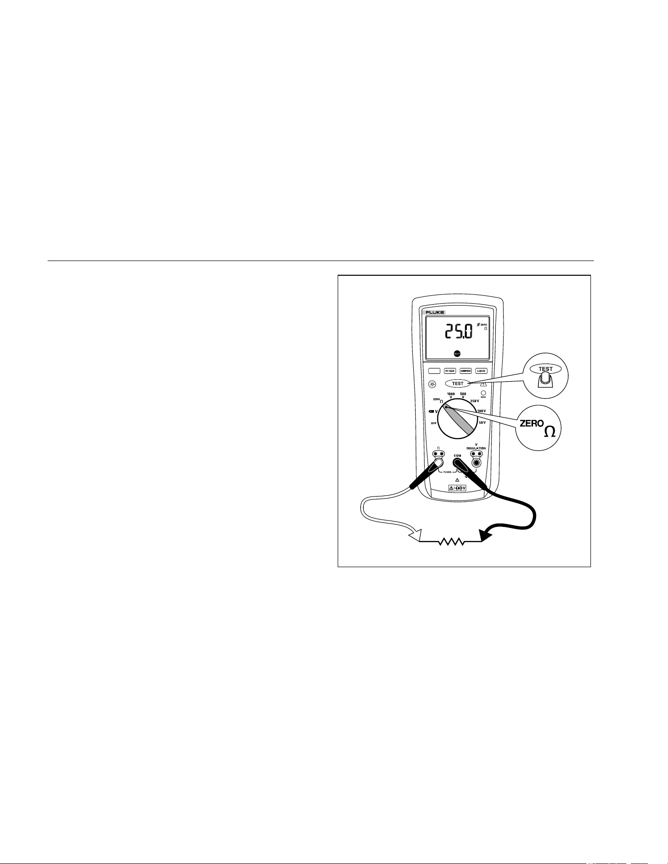
5. Push and hold the T button to start the test. The
t icon appears on the lower portion of the display
until you release the T button. The resistance
reading appears on the primary display until a new
test is started or a different function or range is
selected.
When resistance is higher than the maximum display
range, the Tester displays the > symbol and the
maximum resistance for the range.
.
INSULATION TESTER
1507
bbw04f.eps
Figure 6. Measuring Earth-Bond Resistance
1.888.610.7664 sales@GlobalTestSupply.com
Fluke-Direct.com
Loading ...
Loading ...
Loading ...