Loading ...
Loading ...
Loading ...
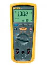
1507/1503
Users Manual
6
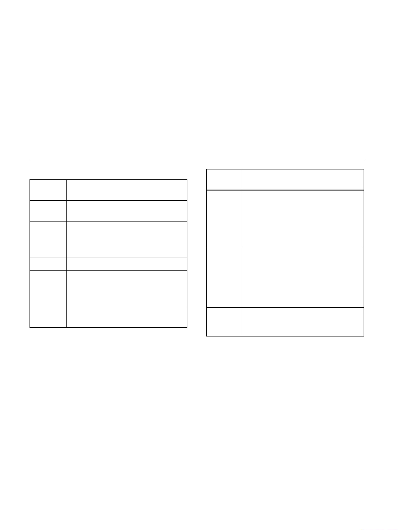
Table 3. Buttons and Indicators
Button/
Indicator
Description
A
Press the blue button to select alternate
measurement functions.
E
Press to configure the Tester for a
polarization index or dielectric absorption
ratio test. The test will start when you press
the T button.
C Sets a pass/fail limit for insulation tests.
L
Test lock. When pressed before the T
button, the test remains active until you
press the lock or test button again to
release the lock.
H
Turns the backlight on and off. The
backlight goes off after 2 minutes.
Button/
Indicator
Description
T
Initiates an insulation test when the rotary
switch is an
INSULATION position. Causes the
Tester to source (output) a high voltage
and measure insulation resistance.
Initiates a resistance test when the rotary
switch is in the ohms position.
I
Unsafe voltage warning. Indicates 30 V or
greater (ac or dc depending on the rotary
switch position) is detected on the input.
Also appears when the display shows 0L in
the b switch positions, and when batt
appears on the display. The Z also appears
when insulation test is active.
J
Pass indicator. Indicates when the
insulation resistance measurement is
greater than the selected compare limit.
1.888.610.7664 sales@GlobalTestSupply.com
Fluke-Direct.com
Loading ...
Loading ...
Loading ...