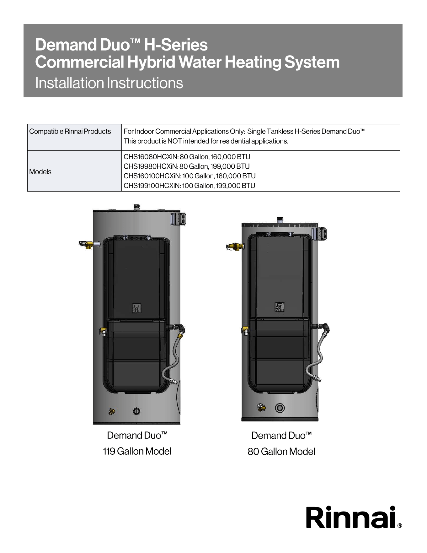
Demand Duo
H-Series with SENSEI CX Installation Instructions 2
If the informaon in these instrucons is not followed exactly, a re
or explosion may result causing property damage, personal injury, or
death.
• Do not store or use gasoline or other ammable vapors and liquids in the vicinity of this or any
other appliance.
• WHAT TO DO IF YOU SMELL GAS
− Do not try to light any appliance.
− Do not touch any electrical switch; do not use any phone in your building.
− Immediately call your gas supplier from a neighbor’s phone. Follow the gas supplier’s
instrucons.
− If you cannot reach your gas supplier, call the re department.
• Installaon and service must be performed by a trained and qualied professional, service agency
or the gas supplier.
WARNING

Demand Duo H-Series with SENSEI CX Installation Instructions 3
READ AND SAVE THESE INSTRUCTIONS
1. Welcome ....................................................................................................................... 4
1.1 To The Installer ....................................................................................................... 4
1.2 To The Owner ........................................................................................................ 4
2. Safety ............................................................................................................................ 5
2.1 Safety Symbols ....................................................................................................... 5
2.2 Safety Precautions .................................................................................................. 5
3. About ............................................................................................................................ 7
3.1 Components ............................................................................................................ 7
3.2 Specifications .......................................................................................................... 8
3.3 Dimensions ............................................................................................................. 10
4. Installation ..................................................................................................................... 12
4.1 Installation Guidelines ............................................................................................. 12
4.2 What You Will Need ................................................................................................ 13
4.3 Choose an Installation Location............................................................................... 13
5. Venting .......................................................................................................................... 17
5.1 Venting Requirements ............................................................................................. 17
5.2 Select a Vent Type .................................................................................................. 19
6. System Plumbing .......................................................................................................... 37
6.1 Pressure Relief Valve Requirements ....................................................................... 37
6.2 Temperature-PRV Requirements ............................................................................ 37
6.3 Connect the Water Heater to the Water Supply ....................................................... 38
6.4 Typical Installations ................................................................................................. 40
6.5 Piping Diagram for Basic Installations ..................................................................... 41
6.6 Piping Diagram for Multiple Unit Installations........................................................... 42
7. Gas and Power Supply .................................................................................................. 43
7.1 Connect the Gas Supply.......................................................................................... 43
7.2 Connect Electricity................................................................................................... 45
7.3 Pump Controller ...................................................................................................... 47
8. Post-Installation Checklist.............................................................................................. 48
9. Maintenance .................................................................................................................. 49
9.1 Replacement Parts .................................................................................................. 50
9.2 Service/Maintenance Log ........................................................................................ 52
10. Warranty ...................................................................................................................... 53
Demand Duo
H-Series with SENSEI CX Installation Instructions 4
Thank you for purchasing Rinnai’s Demand
Duo
H-Series Commercial Hybrid Water
Heating System. This manual provides
information on the installation, operation, and
maintenance of Rinnai’s Demand Duo
H-Series
Commercial Hybrid Water Heating System. Read
this manual completely before installing or
operating the system.
This manual is a supplement to the
Installation and Operation Manual for
Condensing Tankless Water Heaters; refer to
the tankless water heater installation and
operation manual for complete water heater
details, including:
• Parameter Settings (High Altitude
Adjustment, Vent Length Adjustment, and
more)
• Temperature Controller Installation
• Performance Data
• Diagnostic Codes
• A trained and qualified professional must
install the system, inspect it, and leak test it
before use. The warranty may be voided due
to any improper installation.
• The trained and qualified professional should
have skills such as:
− Gas line sizing
− Connecting gas lines, water lines, valves,
and electricity
− Knowledge of applicable national, state,
and local codes
− Installing venting through a wall or roof
− Training in installation of tankless water
heaters. Training on Rinnai Tankless
Water Heaters is accessible at
rinnaipro.myabsorb.com.
• Read all instructions in this manual before
installing the system. The system must be
installed according to the exact instructions in
this manual.
• Proper installation is the responsibility of the
installer.
• When installation is complete, leave this
manual with the system or give the manual
directly to the consumer.
• You must read the entire manual to
properly operate the water heater and to
have regular maintenance performed.
• Keep this manual for future reference.
• As when using any appliance generating
heat, there are certain safety precautions
you should follow. See the Safety
Precautions section for detailed safety
precautions.
• Be sure your water heater is installed by a
trained and qualified professional.
• If installing in the state of Massachusetts,
you must read the Massachusetts State
Gas Regulations section in the tankless
water heater installation and operation
manual (supplied with tankless water
heater).
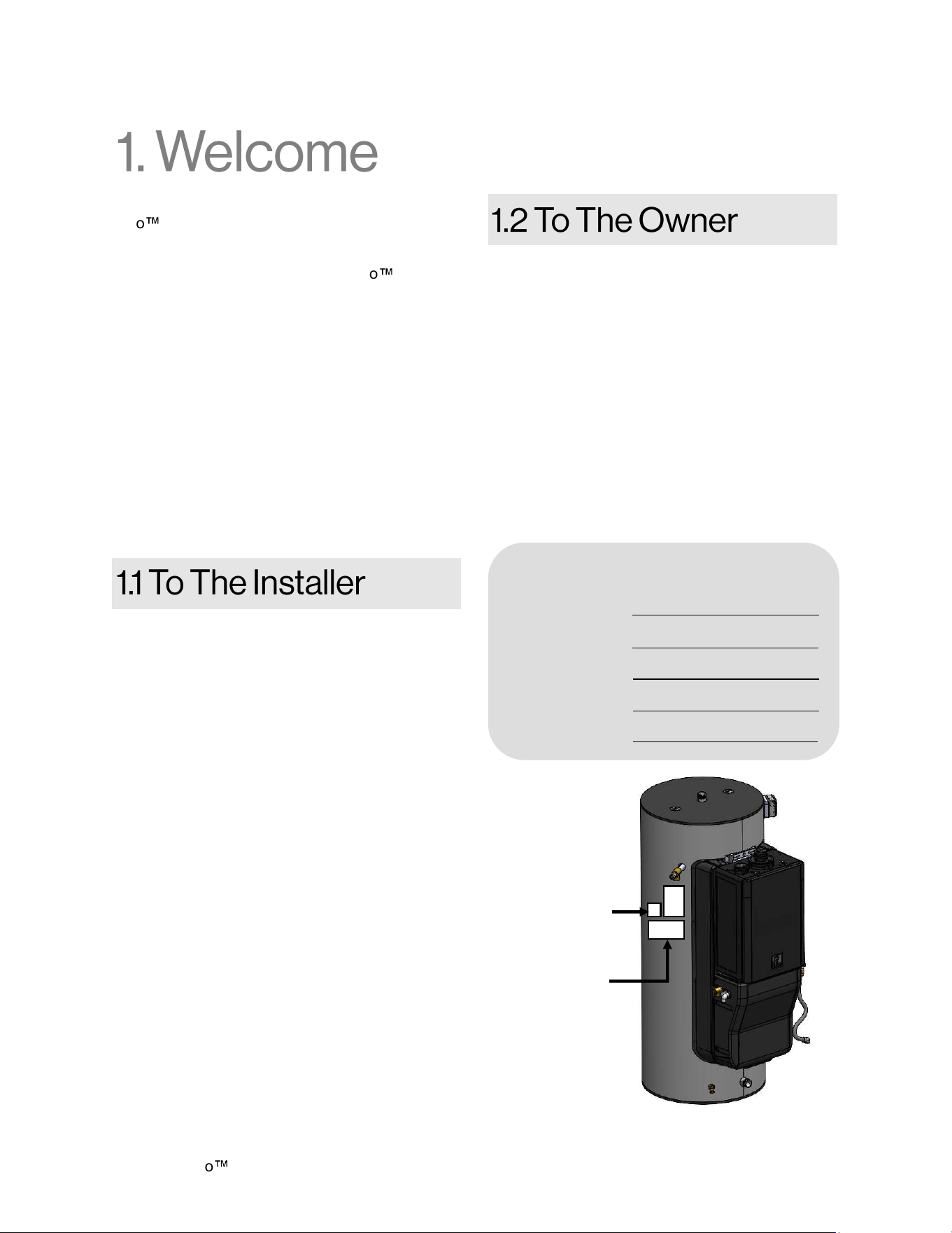
For Your Records
Dealer Name:
Dealer Phone #:
Purchase Date:
Tank Serial #:
System Serial #:
Tank Serial
Number Label
System Serial
Number Label
Figure 1
Demand Duo H-Series with SENSEI CX Installation Instructions 5
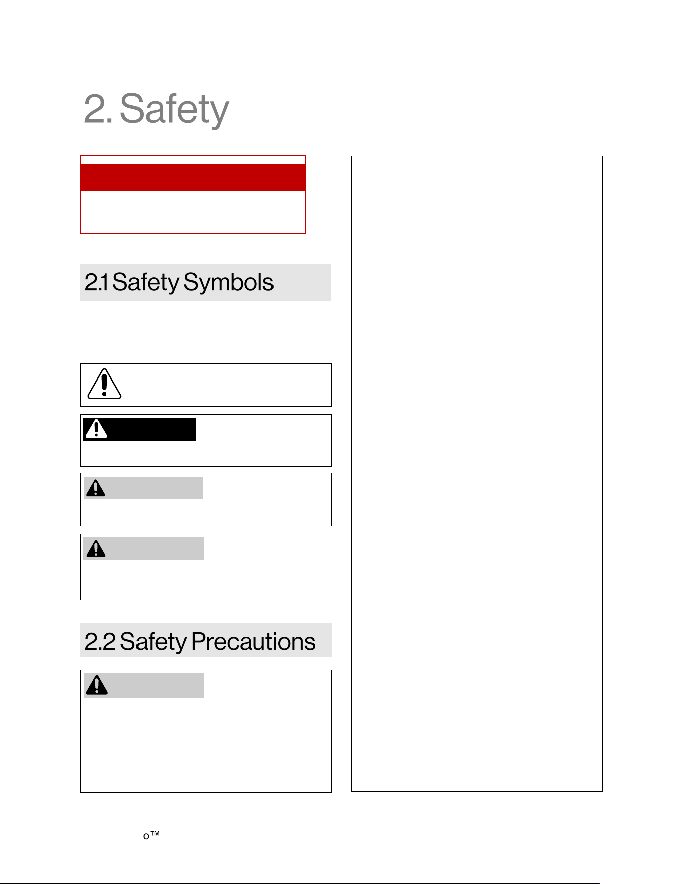
This manual contains the following important
safety symbols. Always read and obey all safety
messages.
This is the safety alert symbol. This
symbol alerts you to potential hazards
that can kill or hurt you and others.
Indicates an imminently
hazardous situation
which, if not avoided, will result in personal injury
or death.
Indicates a potentially
hazardous situation
which, if not avoided, could result in minor or
moderate injury. It may also be used to alert
against unsafe practices.
DANGER
CAUTION
Indicates a potentially
hazardous situation
which, if not avoided, could result in personal
injury or death.
WARNING
WARNING
• Before operating, smell all around the
appliance area for gas. Be sure to smell next
to the floor because some gas is heavier than
air and will settle on the floor.
• Keep the area around the appliance clear and
free from combustible materials, gasoline, and
other flammable vapors and liquids.
• Combustible construction refers to adjacent
walls and ceiling and should not be confused
with combustible or flammable products and
materials. Combustible and/or flammable
products and materials should never be stored
in the vicinity of this or any gas appliance.
• Always check the water temperature before
entering a shower or bath.
• To protect yourself from harm, before
performing maintenance:
− Turn off the electrical power supply by
unplugging the power cord or by turning off
the electricity at the circuit breaker.
(The “On/Off” button on the temperature
controller does not control the electrical
power.)
− Turn off the gas at the gas valve, usually
located immediately before the water
heater.
− Turn off the incoming water supply.
This can be done at the isolation valve
immediately before the water heater or by
turning off the water supply to the building.
• Use only your hand to push in or turn the gas
control knob. Never use tools. If the knob will
not push in or turn by hand, do not try to
repair it; call a licensed professional. Force or
attempted repair may result in a fire or
explosion.
• Do not use this appliance if any part has been
under water. Immediately call a trained and
qualified professional to inspect the appliance
and to replace any part of the control system
and any gas control which has been under
water.
• Do not use substitute materials. Use only
parts certified for the appliance.
• Should overheating occur or the gas supply
fail to shut off, turn off the manual gas control
valve to the appliance.
• Do not use an extension cord or an adapter
plug with this appliance.
• Any alteration to the appliance or its controls
can be dangerous and will void the warranty.
• If a water heater is installed in a closed water
supply system, such as one having a
backflow preventer in the cold water supply
line, means shall be provided to control
thermal expansion. Contact the water
supplier or local plumbing inspector on how to
control thermal expansion.
Topics in this section
• Safety Symbols
• Safety Precautions
Demand Duo
H-Series with SENSEI CX Installation Instructions 6
• Only trained and qualified professionals are
permitted to adjust parameter settings.
• Proper venting is required for the safe
operation of this appliance.
• Flammable liquids such as cleaning solvents,
aerosols, paint thinners, adhesives, gasoline
and propane must be handled and stored with
extreme care. These flammable liquids emit
flammable vapors and when exposed to an
ignition source can result in a fire hazard or
explosion. Flammable liquids should not be
used or stored in the vicinity of this or any
other gas appliance.
• DO NOT operate the water heater without the
front panel installed. The front panel should
only be removed for service/maintenance or
replacing internal components.
• BURN HAZARD. Hot exhaust and vent may
cause serious burns. Keep away from the
water heater. Keep small children and animals
away from the water heater.
• Hot water outlet pipes leaving the water heater
can be hot to touch.
• Do not store or use gasoline or other
flammable vapors and liquids in the vicinity of
this or any other appliance.
• Install the vent system per local and national
codes.
• Do not install this water heater above 10,200 ft
(3,109 m).
• Do not obstruct combustion air to the water
heater.
• Failure to properly vent this appliance can
result in death, personal injury and/or property
damage.
• Rinnai recommends that every home have a
carbon monoxide (CO) alarm inside or directly
outside each bedroom or sleeping area.
Check batteries monthly and replace them
annually.
DO NOT adjust the
internal gas valve. The
design is such that
adjustment is not required. Warranty will be
voided if the internal gas valve is adjusted.
WARNING
• Keep the air intake location free of chemicals
such as chlorine or bleach that produce
fumes. These fumes can damage
components and reduce the life of your
appliance.
• Make sure the water heater and its water
lines are protected from freezing. Damage
due to freezing is not covered by the
warranty.
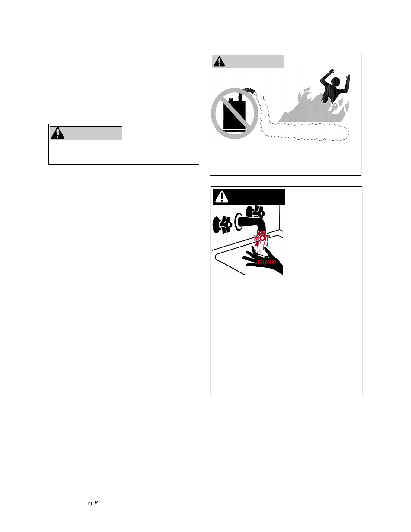
FLAMMABLE
Flammable Vapors
FOR YOUR SAFETY
Do not store or use gasoline or other
flammable vapors and liquids in the vicinity of this
or any other appliance.
Hot water can be
dangerous, especially
for infants or children,
the elderly, or infirm.
There is hot water scald
potential if the thermostat
is set too high.
Water temperatures over
125ºF (51ºC) can cause
severe burns or scalding
resulting in death.
Hot water can cause first degree burns with
exposure for as little as:
• 3 seconds at 140ºF (60ºC)
• 20 seconds at 130ºF (54ºC)
• 8 minutes at 120ºF (48ºC)
Test the temperature of the water before placing
a child in the bath or shower.
Do not leave a child or an infirm person in the
bath unsupervised.
DANGER
WARNING
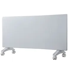
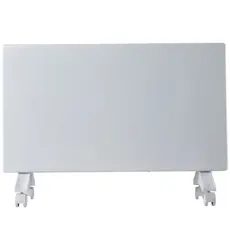
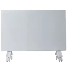
Demand Duo H-Series with SENSEI CX Installation Instructions 7
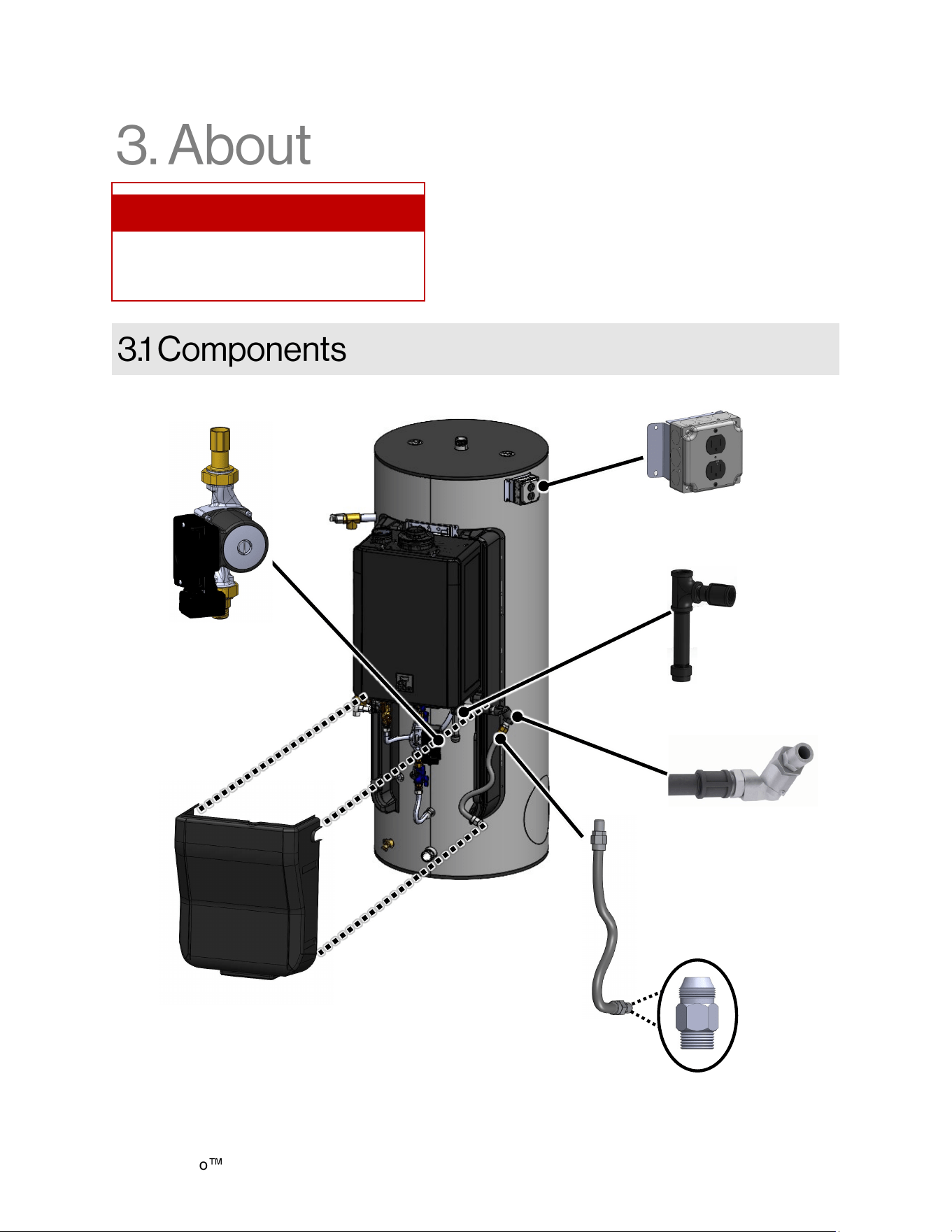
Figure 2: Components
Gas Flex Line
Flare Nut
Adapter
(Supplied but
not installed)
Pump
Electric Conduit
Dirt Leg
Gas Swivel
Front Cover
Topics in this section
• Components
• Specifications
• Dimensions
Demand Duo
H-Series with SENSEI CX Installation Instructions 8
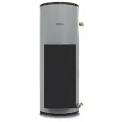
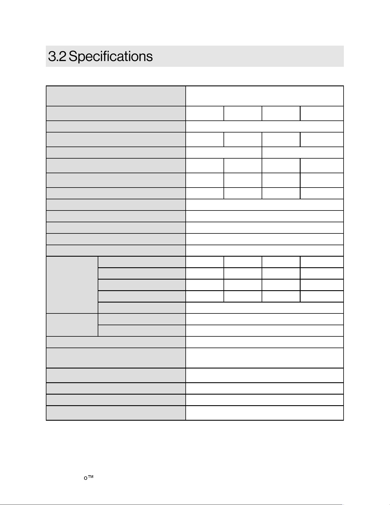
Appliance Type
Commercial Hybrid Water Heating System Consisting of
Condensing Tankless Water Heater, Insulated Storage Tank,
and Pump
Model
CHS199100H
CXi
CHS160100H
CXi
CHS19980H
CXi
CHS16080H
CXi
Minimum Gas Consumption Btu/hr (kW/hr) 15,000 (4.3)
Maximum Gas Consumption Btu/hr (kW/hr)
199,000
(58.3)
160,000
(46.9)
199,000
(58.3)
160,000
(46.9)
Tank Volume 119 Gallons (450 Liters) 80 Gallons (303 Liters)
First Hour Delivery at 100°F Rise
1
317 Gallons
(1,200 Liters)
271 Gallons
(1,026 Liters)
290 Gallons
(1,098 Liters)
244 Gallons
(924 Liters)
Product Weight
431 lb
(195 kg)
429 lb
(195kg)
307 lb
(139 kg)
305 lb
(138 kg)
Sound Level 49 dB 48 dB 49 dB 48 dB
Installation Type Internal (Indoor) Commercial Applications
Category Category IV
Ignition System Direct Electronic Ignition
Water Supply Pressure 150 PSI (Maximum)
Temperature Setting 98°F (37°C) to 185°F (85°C)
Electrical Data
Normal 279 W 244 W 279 W 244 W
Standby 44 W 44 W 44 W 44 W
Freeze Protection 148 W 148 W 148 W 148 W
Max Current 5.5 A 5.5 A 5.5 A 5.5 A
Fuse Tankless Water Heater Engine: 10 Amps
Gas Supply
Pressure
2
Natural 3.5 - 10.5 in. w.c.
Propane 8.0 - 13.5 in. w.c.
By-Pass Flow Control Electronic
Connections
Gas Supply Inlet: 3/4 in. MNPT
Hot Water Outlet: 1-1/2 in. MNPT
Cold Water Inlet: 1-1/2 in. MNPT
Electric Connections
Appliance: AC 120 Volts, 60Hz.
Integrated Temperature Controller: DC 12 Volts (Digital)
Water Temperature Control Simulation Feed Forward and Feedback
ENERGY STAR® Certified (Tankless engine) Yes
Complies with South Coast Air Quality Management
District 14 ng/J or 20 ppm NOx Emission Levels
Yes
1
First Hour Delivery Rating is a theoretical calculation based on 70% usable tank capacity
(Tank Capacity x .70 + (recovery) = First Hour Delivery Rating
2
The maximum gas supply pressure must not exceed the value specified by the manufacturer.
3
Temperature limit of 185°F can be achieved using optional MCC-601 controller.
Rinnai products are continually being updated and improved; therefore, specifications are subject to change without prior notice.
Table 1: Specifications
Demand Duo H-Series with SENSEI CX Installation Instructions 9
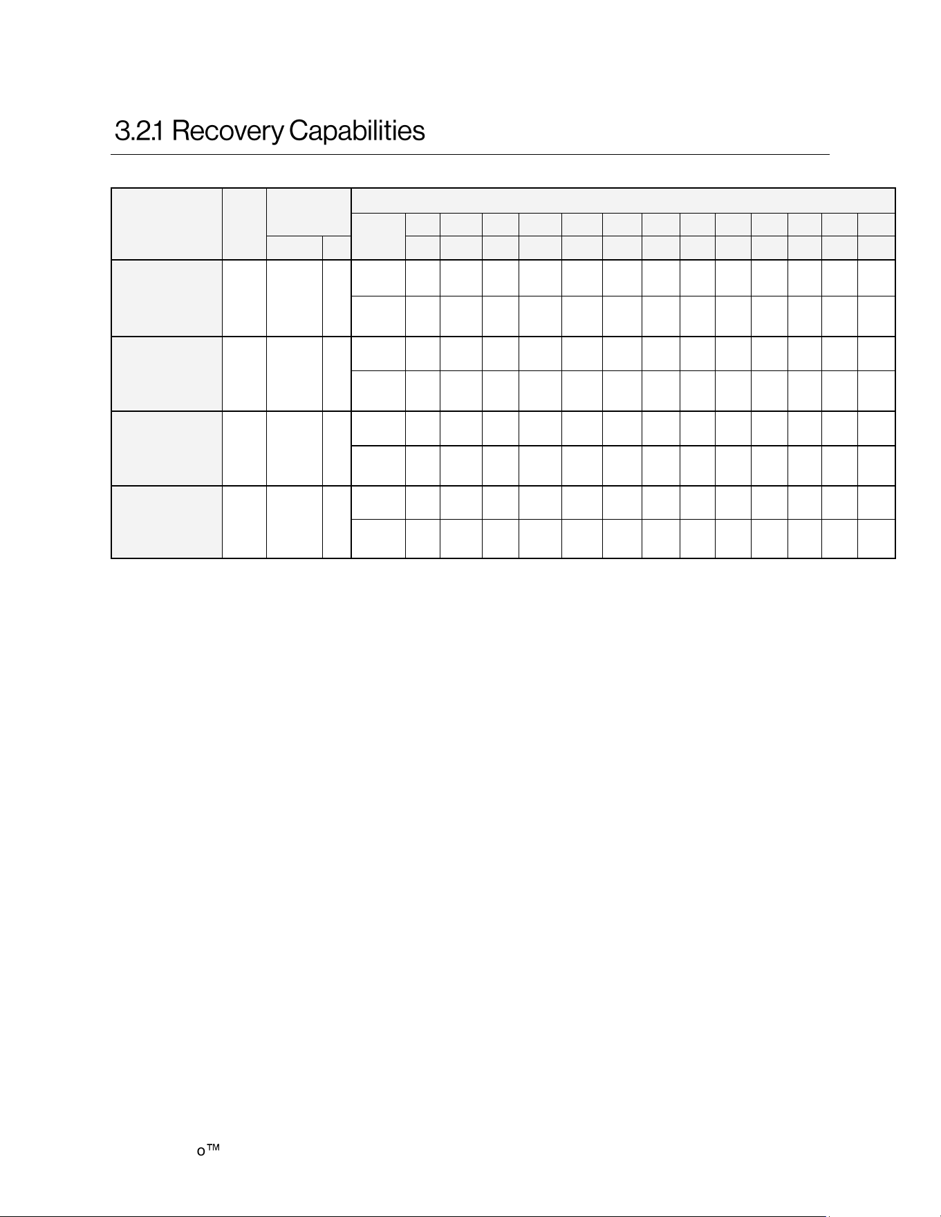
Product Number
Gas
Type
Input
U.S. Gallon / HR Liters / HR at Temperature Rise Indicated
Tank
Capacity
°F 30°F 40°F 50°F 60°F 70°F 80°F 90°F 100°F 110°F 120°F 130°F 140°F
BTU/HR kW °C 17°C 22°C 28°C 33°C 39°C 44°C 50°C 56°C 61°C 67°C 72°C 78°C
CHS199100HCXi NG/LP 199,000 58
119
Gals.
GPH 780 585 468 390 334 292 260 234 213 195 180 167
450
Liters
LPH 2,953 2,214 1,771 1,476 1,264 1,105 984 886 806 738 681 632
CHS160100HCXi NG/LP 160,000 47
119
Gals.
GPH 627 470 376 314 269 235 209 188 171 157 145 134
450
Liters
LPH 2,374 1,780 1,424 1,187 1,017 890 791 712 647 593 548 509
CHS19980HCXi NG/LP 199,000 58
80
Gals.
GPH 780 585 468 390 334 292 260 234 213 195 180 167
303
Liters
LPH 2,953 2,214 1,771 1,476 1,264 1,105 984 886 806 738 681 632
CHS16080HCXi NG/LP 160,000 47
80
Gals.
GPH 627 470 376 314 269 235 209 188 171 157 145 134
303
Liters
LPH 2,374 1,780 1,424 1,187 1,017 890 791 712 647 593 548 509
Table 2: Recovery Capacity / Input
Demand Duo
H-Series with SENSEI CX Installation Instructions 10
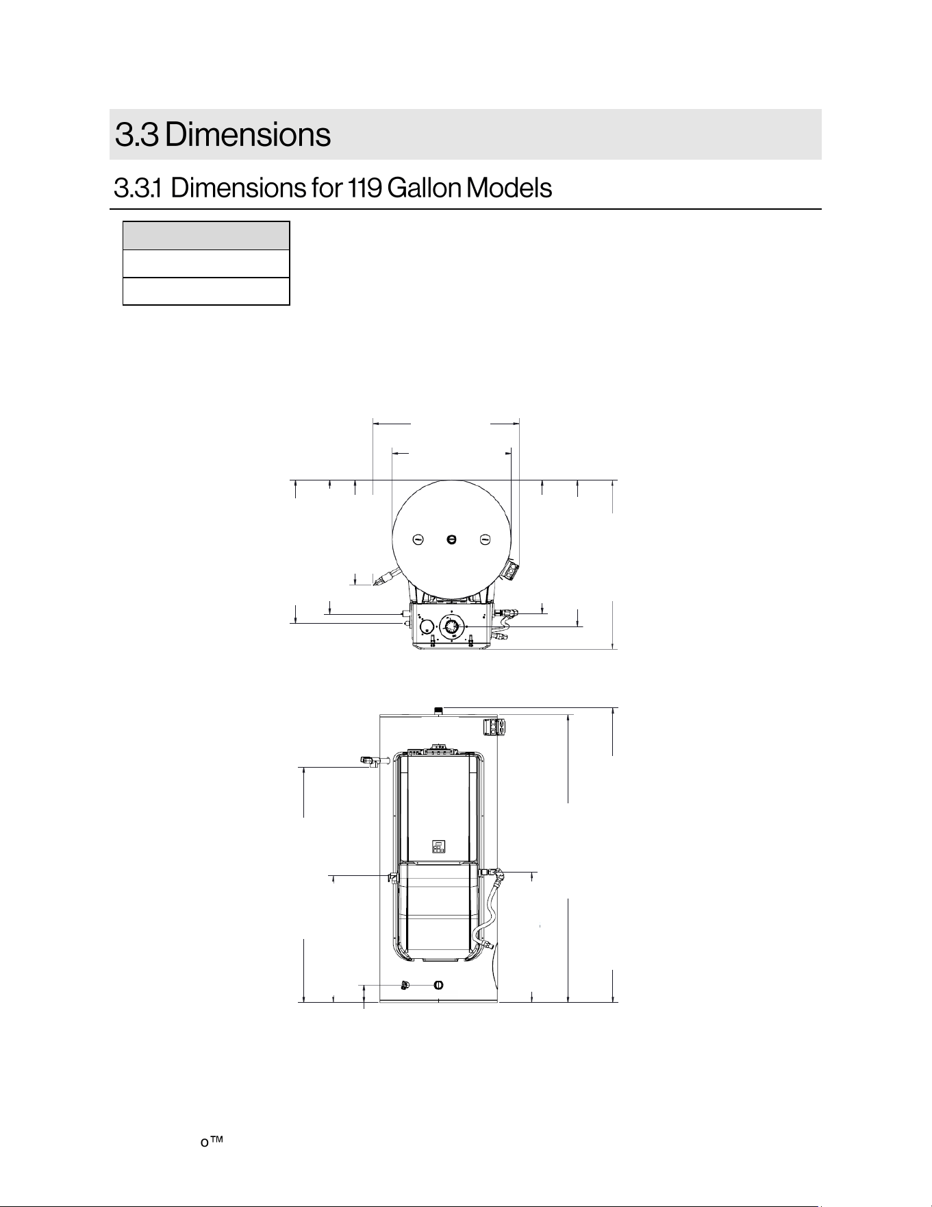
RIGHT
LEFT
Measurements below are
shown in inches (mm).
Models
CHS199100HCXi
CHS160100HCXi
Figure 3: Dimensions
TOP
34.77 (883)
Ø 28.30 (718)
31.74 (806) Gas
34.90 (887) Vent
40.28 (1023)
24.94 (633)
T&P
30.88 (784) PRV
34.13 (867)
Condensate
FRONT
4.20 (107)
1-1/2 in.
MNPT Cold
30.56 (776) PRV
56.74 (1,441) T&P
31.36 (797) Gas
69.40 (1,762)
71.10 (1,805) 1-1/2 in. MNPT Hot
Demand Duo H-Series with SENSEI CX Installation Instructions 11
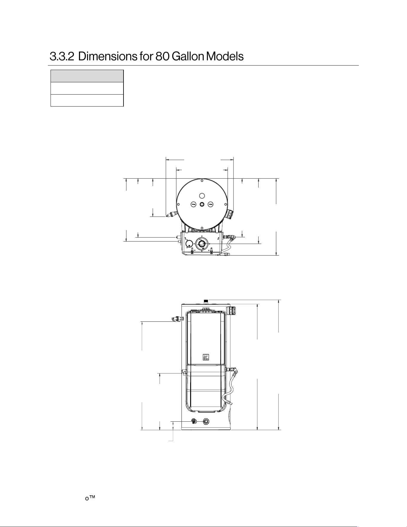
Models
CHS19980HCXi
CHS16080HCXi
Measurements below
are shown in inches
(mm).
Figure 4: Dimensions
TOP
31.75(807)
Ø 24.25 (616)
27.31 (694) Gas
30.59 (777) Vent
36 (914)
29.53 (750)
Condensate
27.59 (701) PRV
16.58
(421)
T&P
FRONT
53.91 (1369) T&P
28.08 (713)
PRV
62.69 (1,592)
64.71 (1,643)
1-1/2 in. MNPT Hot
4.20(107)1-1/2 in.
MNPT Cold
Demand Duo
H-Series with SENSEI CX Installation Instructions 12
THIS SECTION IS INTENDED FOR THE
INSTALLER
Installer qualifications: A trained and qualified
professional must install the appliance,
inspect it, and leak test the Demand Duo
before use. The warranty may be voided due
to any improper installation. The trained and
qualified professional should have skills such
as: Gas sizing; Connecting gas lines, water
lines, valves, and electricity; Knowledge of
applicable national, state, and local codes;
Installing venting through a wall or roof; and
training in installation of tankless water
heaters. Training for Rinnai Tankless Water
Heaters is accessible online at
rinnaipro.myabsorb.com.
• This water heater is suitable for combination
water heating and space heating and not
suitable for space heating applications only.
• The installation must conform with local
codes or, in the absence of local codes, with
the National Fuel Gas Code, ANSI Z223.1/
NFPA 54, or the Natural Gas and Propane
Installation Code, CSA B149.1.
• The appliance, when installed, must be
electrically grounded in accordance with local
codes or, in the absence of local codes, with
the National Electrical Code, ANSI/NFPA 70,
or the Canadian Electrical Code, CSA C22.1.
When installing the Demand Duo
, follow these
guidelines:
DO NOT install the Demand Duo
Commercial Hybrid Water Heating System
outdoors.
DO NOT install the water heater in an area
where water leakage of the unit or
connections will result in damage to the
area adjacent to the appliance or to lower
floors of the structure. When such locations
cannot be avoided, it is required that a
suitable drain pan, adequately drained, be
installed under the water heater. The pan
must not restrict combustion air flow.
DO NOT install the water heater in an area
with negative air pressure.
DO NOT obstruct the flow of combustion
and ventilation air.
DO NOT use this appliance in an
application such as a pool or spa heater
that uses chemically treated water. This
appliance is suitable for filling large or
whirlpool spa tubs with potable water.
DO NOT use substitute parts that are not
authorized for this appliance.
Topics in this section
• Installation Guidelines
• What You Will Need
• Choose an Installation Location
• The appliance and its main gas valve must be
disconnected from the gas supply piping
system during any pressure testing of that
system at test pressures in excess of 1/2 psi
(3.5 kPa) (13.84 in W.C.). For system testing
at pressures less than or equal to 1/2 psi
(3.5 kPa) (13.84 in W.C.) the appliance must
be isolated from the gas supply piping by
closing its individual manual shutoff valve.
• You must follow the installation instructions
and those in the venting section for adequate
combustion air and exhaust.
• If a water heater is installed in a closed water
supply system, such as one having a
backflow preventer in the cold water supply
line, means shall be provided to control
thermal expansion. Contact the water supplier
or local plumbing inspector on how to control
thermal expansion.
• Should overheating occur or the gas supply
fail to shut off, turn off the manual gas control
valve to the appliance.
• Combustion air must be free of chemicals,
such as chlorine or bleach, that produce
fumes. These fumes can damage
components and reduce the life of your
appliance.
Demand Duo H-Series with SENSEI CX Installation Instructions 13
Carefully unpack your system package and verify
the following contents are included.
If any items are damaged or missing, contact
your local dealer/distributor or call Rinnai
Customer Care at 1-800-621-9419. Do not
attempt to use any item that appears damaged.
Items included with system:
• Rinnai Demand Duo
Commercial Hybrid
Water Heating System
• Temperature and Pressure Relief Valve
(pre-installed on tank)
• Pressure Relief Valve (pre-installed on the
tankless water heater)
• Installation and Operation Manual (this
manual)
• Installation and Operation Manual for
Tankless Water Heater
• 2 in. PVC Vent Screens (x2) and Vent
Screen Screws
• Gas Flex/Union
To avoid danger of
suffocation, keep
plastic bags away from
babies, small children and pets. Do not use
these bags in cribs, beds, carriages, or
playpens. The bags are not a toy.
WARNING
• Threading machine with heads and oiler
• Core drill with diamond head
• Torch set
• Copper tubing cutter
• Steel pipe cutter
• Heat tape
• 5/8 in. ID PVC flexible tubing
• Electrical wire
• Concrete wall anchors
• Optional pipe cover
• PVC glue/cement and primer
• 2 conductor 22 AWG wire for controller
• Single gang electrical box
• Wire nuts
• Unions and drain valves
• Drain pan
• Earthquake strap
When selecting an installation location, you must
ensure that clearances will be met and that the
vent length will be within required limits. Consider
the installation environment, water quality, and
need for freeze protection. Requirements for the
gas line, water lines, electrical connection, and
condensate disposal can be found in their
respective installation sections in this manual.
This section provides information on the
importance of water quality to the Rinnai
Tankless Water Heater. The information is
intended to serve as general guidelines only and
is not a complete list of water quality guidelines.
Consideration of care for your water heater
should include evaluation of water quality.
The water must be potable, free of corrosive
chemicals, sand, dirt, or other contaminants. It is
up to the installer to ensure the water does not
contain corrosive chemicals or elements that can
affect or damage the Rinnai Commercial Hybrid
Water Heating System. Water that contains
chemicals exceeding the levels below can
damage the Rinnai Tankless Water Heater.
Replacement of components due to water
quality damage is not covered by the warranty.
• Pipe wrenches (x2)
• Phillips Head screwdriver
• Adjustable pliers
• Wire cutters
• Gloves
• Safety glasses
• Level
• Soap or gas leak detector solution
• Approved venting
• Teflon tape (recommended) or pipe com-
pound
• Pipe insulation
• Hammer drill with concrete bits
• Saw
Demand Duo
H-Series with SENSEI CX Installation Instructions 14
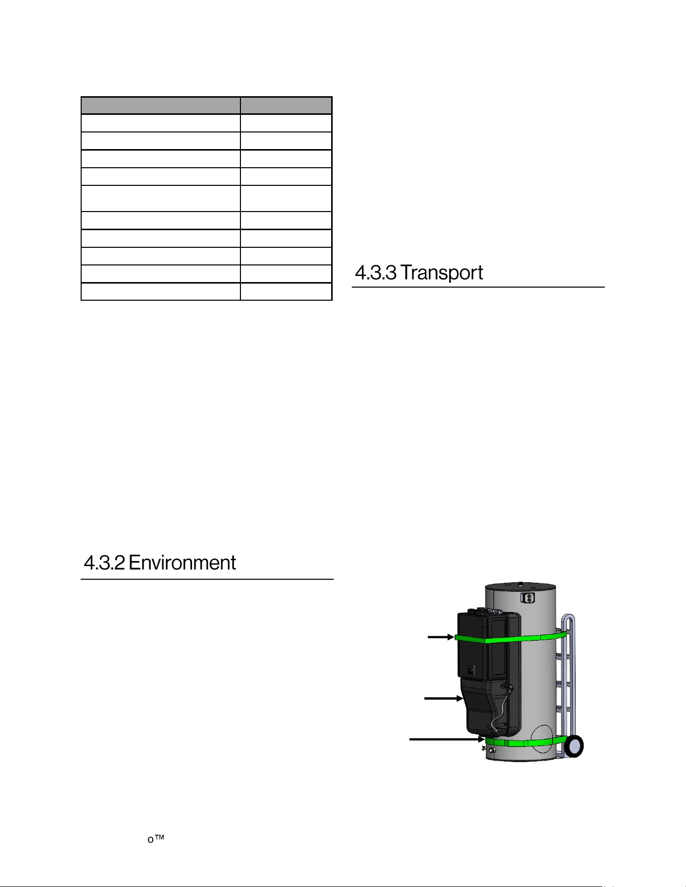
1. Choose the right hand truck to support the
weight and size of the water heater. Refer to
section “3.2 Specifications” in this manual for
specific weights and dimensions.
2. Use proper lifting techniques to load the
water heater onto the hand truck:
• Position the water heater onto the hand
truck so the weight is evenly balanced
and the tank is touching the rails of the
hand truck.
• Secure the water heater to the hand
truck:
− Position STRAP A around the
tankless unit as illustrated below.
− Position STRAP B around the base
of the tank below the lower
enclosure. Do not add strap around
the exhaust or vent connection.
Contaminant Maximum Level
Total Hardness Up to 200 mg/L
Aluminum * Up to 0.2 mg/L
Chlorides * Up to 250 mg/LL
Copper * Up to 1.0 mg/L
Dissolved Carbon Dioxide
(CO2)
Up to 15.0 mg/L
Iron * Up to 0.3 mg/L
Manganese * Up to 0.05 mg/L
pH * 6.5 to 8.5
TDS (Total Dissolved Solids) * Up to 500 mg/L
Zinc * Up to 5 mg/L
* Source: Part 143 National Secondary Drinking
Water Regulations
Air surrounding the water heater, venting, and
vent termination(s) is used for combustion and
must be free of any compounds that cause
corrosion of internal components. These include
corrosive compounds that are found in aerosol
sprays, detergents, bleaches, cleaning solvents,
oil based paints/varnishes, and refrigerants. The
air in beauty shops, dry cleaning stores, photo
processing labs, and storage areas for pool
supplies often contains these compounds.
Therefore, it is recommended to install as a direct
vent (use outside air for combustion). In
applications utilizing room air where there are
high levels of particulates, Rinnai offers a room
air screen.
The water heater, venting, and vent
termination(s) should not be installed in any
areas where the air may contain these corrosive
compounds.
If you install this water heater in an area that is
known to have hard water or that causes scale
build-up, the water must be treated and may
require a more frequent flushing schedule.
This water heater includes a service indicator
(Service Soon, SS). When selected in the
parameter settings, an SS code will display on
the controller indicating that it is time to flush and
service the water heater. Scale build-up is
caused by hard water and can be accelerated if
the water heater is set at a temperature above
120°F.
Rinnai offers Southeastern Filtration’s
“ScaleCutter Water Conditioning System” that
offers superior lime scale prevention and
corrosion control by feeding a blend of control
compounds into the cold water supply.
Lower
Enclosure
Strap A
Strap B
Figure 5: Transport
Table 3: Water Quality Guidelines
Do not store or use gasoline or other flammable
vapors and liquids in the vicinity of this or ay
other appliance.
Flammable liquids such as cleaning solvents,
aerosols, paint thinners, adhesives, gasoline
and propane must be handled and stored with
extreme care. These flammable liquids emit
flammable vapors and when exposed to an
ignition source can result in a fire hazard or
explosion. Flammable liquids should not be used
or stored in the vicinity of this or any other gas
appliance.
Demand Duo H-Series with SENSEI CX Installation Instructions 15
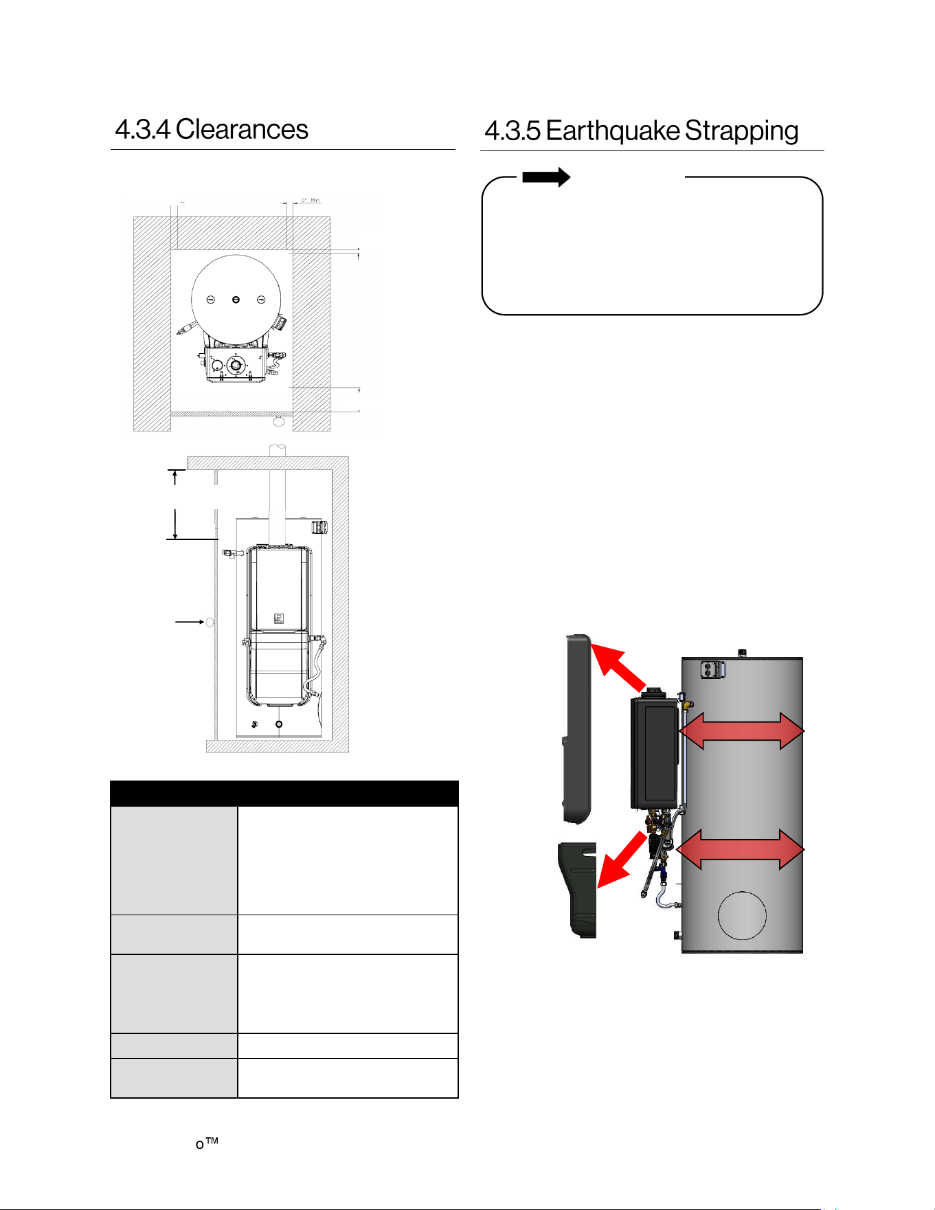
Location Clearance
Top
2 in. (51 mm)
(0 in. from vent components)
** Clearance for servicing the
anode rods is 54 in. (137 cm)
from the top of the water
heater.
Bottom 0 in.
Front
6 in. (152 mm)
* Clearance for servicing is 24
in. (610 mm) in front of water
heater.
Back 0 in.
Sides
(Left and Right)
0 in.
IMPORTANT
Product installed in the state of California
must be braced, anchored, or otherwise
secured to avoid motion or falling during an
earthquake. Contact the California Office of
the State Architect located at 1102 Q Street,
Suite 5100, Sacramento, CA 95811 for
instructions.
1. Loosen screws along the perimeter of the
plastic enclosures.
2. Remove plastic enclosures.
3. Position straps around the tank per the
requirements of California Office of the State
Architect. DO NOT POSITION THE STRAPS
OVER PIPE, FITTINGS or WIRE.
4. Replace the plastic enclosures. Modification
of the plastic enclosures may be necessary
to fit the enclosures over the earthquake
straps.
5. Replace the screws around the perimeter of
the plastic enclosures.
Table 4: Clearances
Figure 7: Earthquake Strapping
STRAP
Plastic
Enclosure
(Side)
STRAP
Plastic
Enclosure
(Bottom)
Figure 6: Clearances
0 in. Minimum
0 in. Minimum
0 in. Minimum
*6 in. Minimum
Door
** 12 in. Minimum
Demand Duo
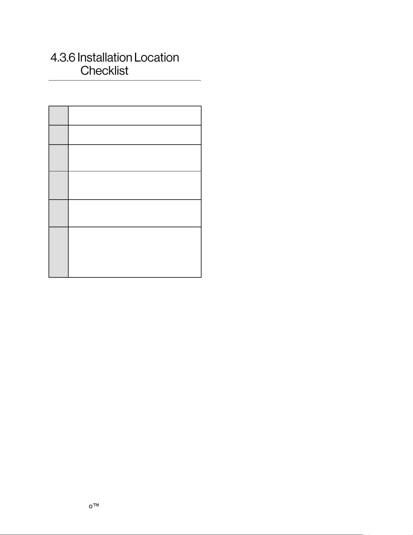
H-Series with SENSEI CX Installation Instructions 16
□
The water heater is not exposed to
corrosive compounds in the air.
□
The water heater location complies with
the required clearances.
□
The planned combustion air and exhaust
termination locations meet the required
clearances.
□
The water supply does not contain
chemicals or exceed total hardness that
will damage the heat exchanger.
□
A standard 3 prong 120 VAC, 60 Hz
properly grounded wall outlet or other
120 VAC, 60 Hz source is available.
□
The installation must conform with local
codes or, in the absence of local codes,
with the National Fuel Gas Code, ANSI
Z223.1/NFPA 54, or the Natural Gas and
Propane Installation Code, CSA B149.1.
Use this checklist to ensure you have selected
the correct location for the water heater.
Demand Duo H-Series with SENSEI CX Installation Instructions 17
• When installed as direct vent, refer to the
Tankless Water Heater Installation and
Operation Manual for a complete list of
approved vent manufacturers and products.
You must use vent components that are
certified and listed with the water heater
model.
• Avoid dips or sags in horizontal vent runs by
installing supports per the vent
manufacturer’s instructions.
• Support horizontal vent runs every four feet
and all vertical vent runs every six feet or in
accordance with local codes.
• Venting should be as direct as possible with
a minimum number of pipe fittings.
• Engineered vent systems must be firmly
pressed together so that the gaskets form an
air tight seal.
• The vent piece connected to the water heater
must be secured with one self-tapping screw.
• When installed as Non-Direct Vent (Room
Air), the venting must be Category IV and of
a type listed by a national recognized testing
agency or PVC (when allowed by local code).
WARNING
DO NOT use cellular core PVC/CPVC.
DO NOT use Radel or galvanized
material to vent this appliance.
DO NOT cover non-metallic vent pipe
and fittings with thermal insulation.
DO NOT combine vent components from
different manufacturers.
DO NOT reduce the vent diameter.
DO NOT connect the venting system with
an existing vent or chimney.
DO NOT common vent with the vent pipe
of any other manufacturer’s water heater
or appliance.
IMPORTANT
For venting information not specified in this
section, refer to the Installation and Operation
Manual for Condensing Tankless Water
Heaters (supplied with each tankless water
heater). This manual includes complete
venting information, including approved vent
manufacturers and terminations.
Topics in this section
• Venting Requirements
• Select a Vent Type
IMPORTANT
If it becomes necessary to access an
enclosed vent system for service or
repairs, Rinnai is not responsible for any
costs or difficulties in accessing the vent
system. The warranty does not cover
obtaining access to a vent system in an
enclosed environment.
• If the vent system is to be enclosed, it is
suggested that the design of the enclosure
shall permit inspection of the vent system.
The design of such enclosure shall be
deemed acceptable by the installer or the
local inspector.
• Refer to the instructions of the vent system
manufacturer for component assembly
instructions.
Demand Duo
H-Series with SENSEI CX Installation Instructions 18
1. Install the water heater.
2. Determine the
termination method
- horizontal or vertical
, concentric, or twin
pipes, etc.
3. Determine proper location for wall or roof
penetration for each termination.
4. Install termination assembly as described in
this manual
or in the vent manufacturer’s
installation instructions.
5. Install air and vent piping from water heater
to termination.
6. Slope horizontal exhaust run towards the
water heater 1/4 in per foot. DO NOT slope
combustion air pipe towards water heater.
7. Install vent supports and brackets allowing
for movement from expansion, or as per
vent manufacturer’s instructions or local
code requirements.
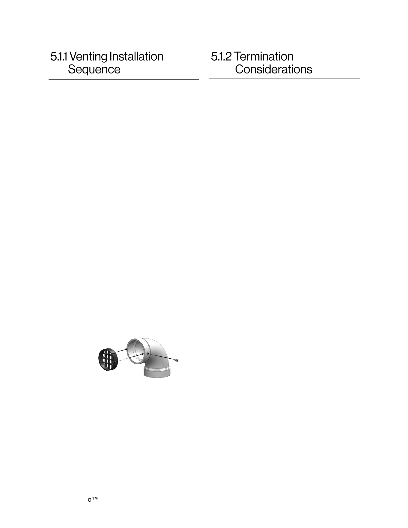
8. Install vent screen (supplied with water
heater) on PVC combustion air and exhaust
termination elbows as illustrated below.
• Press vent screen inside of termination
piece/elbow.
• Secure vent screen to the elbow with
screw provided.
Check to determine whether local codes
supersede the following clearances:
• Avoid termination locations near a dryer
vent.
• Avoid termination locations near
commercial cooking exhaust.
• Avoid termination locations near any air
inlets.
• You must install a vent termination at least
12 in above the ground or anticipated
snow level.
The vent for this appliance shall not terminate:
• Over public walkways.
• Near soffit vents or crawl space vents or
other area where condensate or vapor
could create a nuisance or hazard or
cause property damage.
• Where condensate or vapor could cause
damage or could be detrimental to the
operation of regulators pressure relief
valves, or other equipment.
Listed below are important considerations for
locating vent termination under a soffit
(ventilated or unventilated or eave vent; or to a
deck or porch):
• Do not install vent termination under a
soffit vent such that exhaust can enter the
soffit vent.
• Install vent termination such that exhaust
and rising moisture will not collect under
eaves. Discoloration to the exterior of the
building could occur if installed too close.
• Do not install the vent termination too
close under the soffit where it could
present recirculation of exhaust gases
back into the combustion air part of the
termination.
Figure 8: Vent Screen Assembly
Demand Duo H-Series with SENSEI CX Installation Instructions 19
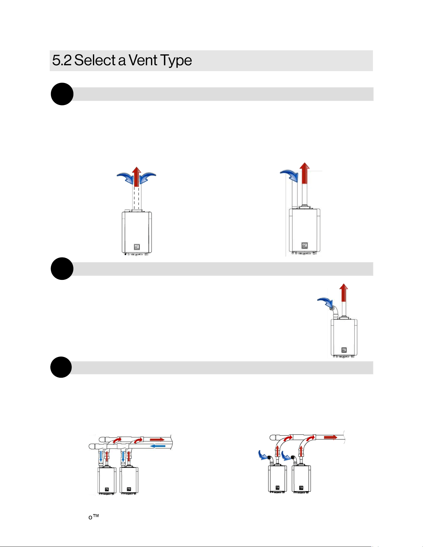
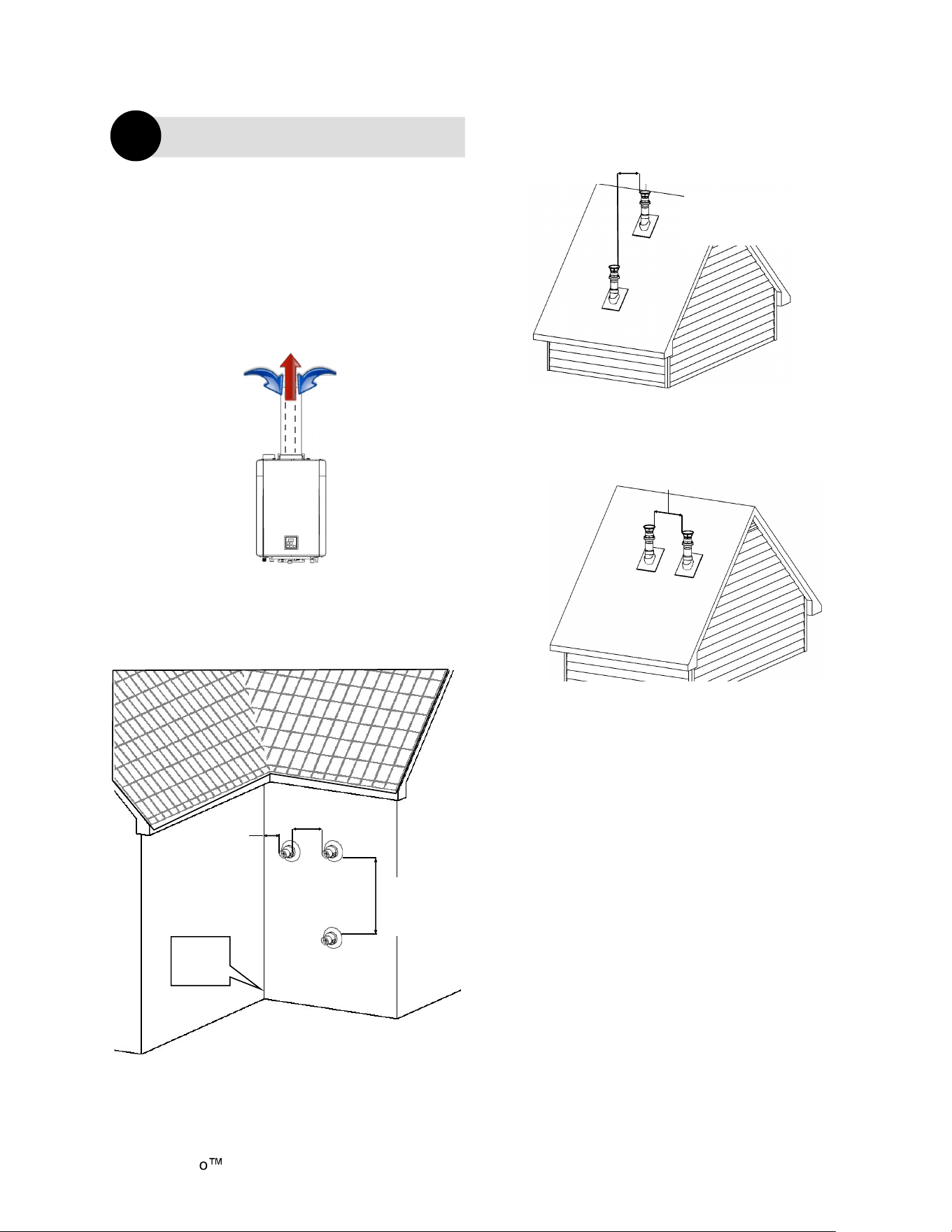
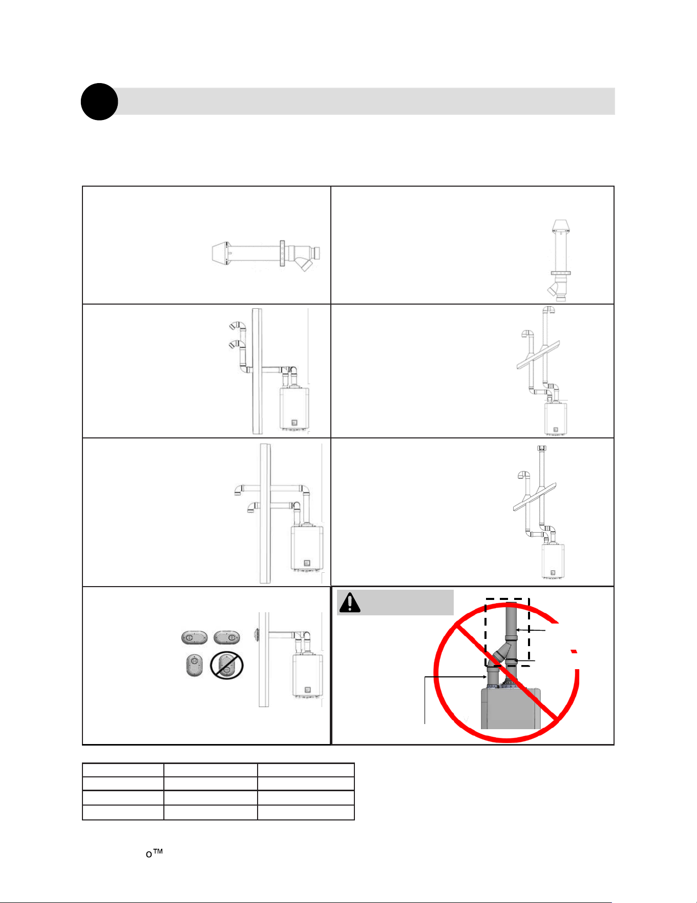
Three types of venting options are available:
Concentric Pipe
Combustion air and exhaust vent directly
through a single concentric connection. Hot
exhaust exits through the interior tube, while
combustion air enters through the outer layer.
Direct Vent
Non-Direct (Room Air) Vent
Multiple water heaters sharing a combustion air
header and a separate exhaust header that vents
directly through separate penetrations to the
outside.
Twin Pipe
Combustion air and exhaust vent directly
through separate penetrations.
Room air is used for combustion while exhaust
vents to the outside.
Multiple water heaters using room air for
combustion while sharing an exhaust
header that vents directly to the outside.
Direct Vent (Concentric Pipe and Twin Pipe)
1
Non-Direct Vent (Room Air)
2
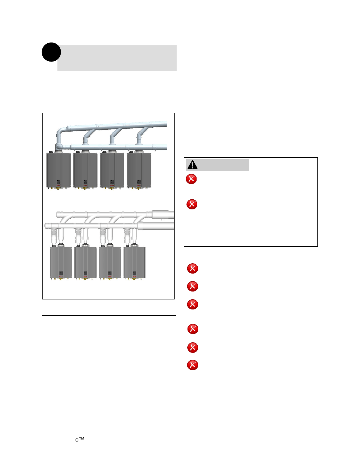
Common Vent (Indoor Units Only. Direct Vent and Non-Direct/Room Air Vent)
3
Figure 9
Figure 10
Figure 11
Figure 12 Figure 13
Room Air
For Combuson
Exhaust
Combuson
air
Combuson
air
Exhaust
Combuson
air
Exhaust
Combuson
air
Combuson Air
Exhaust
Exhaust
Demand Duo
H-Series with SENSEI CX Installation Instructions 20
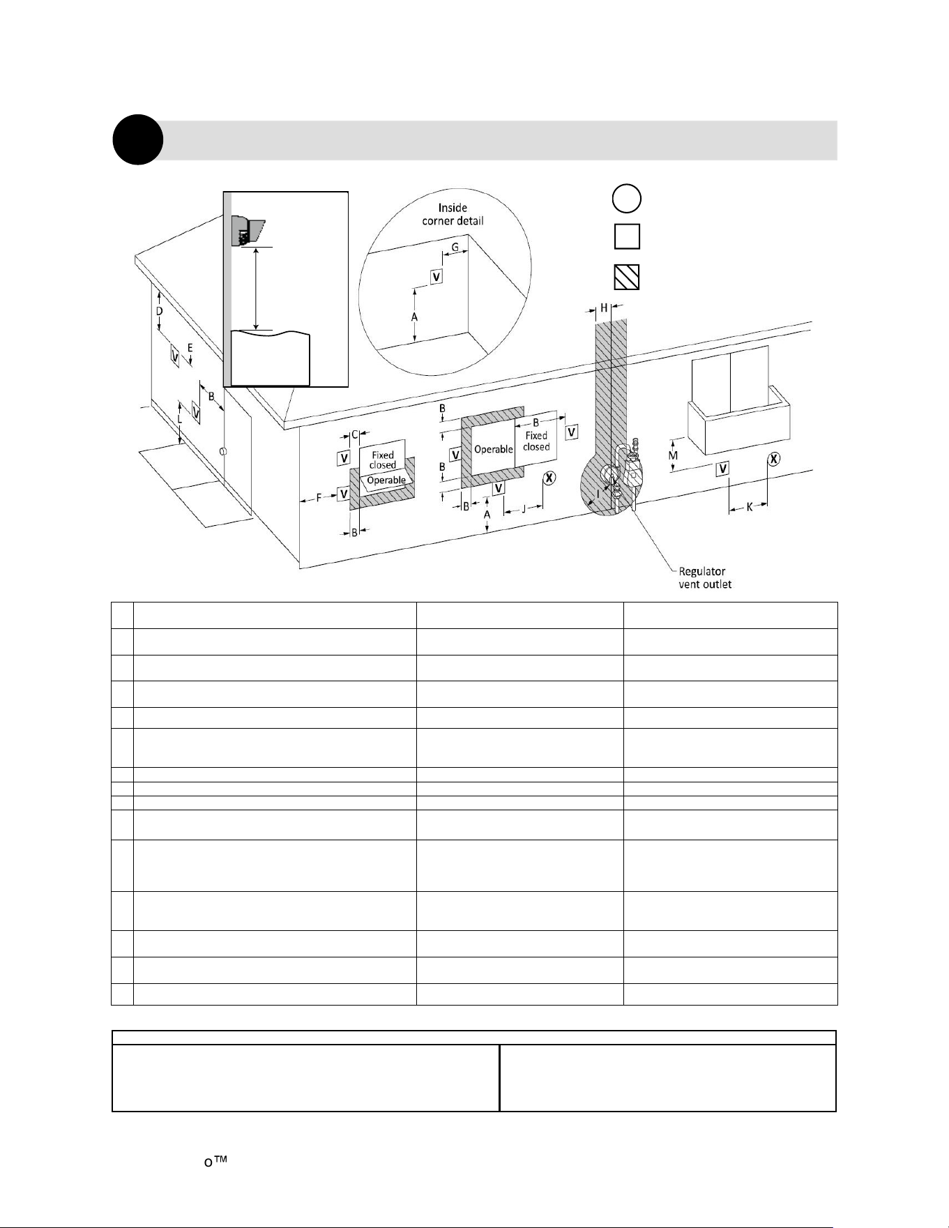
Canadian Installaons
(CSA B149.1)
U.S. Installaons
(ANSI Z223.1 /NFPA 54)
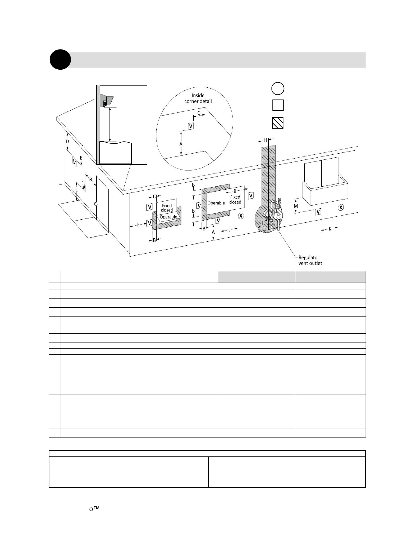
Ref Descripon Direct Vent (Indoor Unit) Direct Vent (Indoor Unit)
A Clearance above grade, veranda, porch, deck, or balcony 12 in. (30 cm) 12 in. (30 cm)
B Clearance to window or door that may be opened 36 in. (91 cm) 12 in. (30 cm)
C Clearance to permanently closed window * *
D
Vercal clearance to venlated sot, located above the terminal
within a horizontal distance of 2 (61 cm) from the center line of the
terminal
* *
E Clearance to unvenlated sot * *
F Clearance to outside corner * *
G Clearance to inside corner * *
H
Clearance to each side of center line extended above meter/regulator
assembly
* *
I Clearance to service regulator vent outlet
Above a regulator within 3
(91 cm) horizontally of the vercal
center line of the regulator vent
outlet to a maximum vercal
distance of 15 (4 m)
*
J
Clearance to non-mechanical air supply inlet to building or the
combuson air inlet to any other appliance
36 in. (91 cm) 12 in. (30 cm)
K Clearance to a mechanical air supply inlet 6 (1.83 m)
3 (91 cm) above if within
10 (3 m) horizontally
L
Clearance above paved sidewalk or paved driveway located on public
property
7 (2.13 m) [1] *
M Clearance under veranda, porch, deck, or balcony 12 in. (30 cm) [2] *
Figure 14: Direct Vent Termination Clearances (For Concentric and Twin Pipe)
Direct Vent (Concentric Pipe and Twin Pipe)
1
Clearance to opposite wall is 24 in. (60 cm).
[1] A vent shall not terminate directly above a sidewalk or paved
driveway that is located between two single family dwellings and
serves both dwellings.
[2] Permied only if veranda, porch, deck, or balcony is fully open on a
Clearances are in accordance with local installaon codes and the
requirements of the gas supplier. (Dégagement conforme aux codes
d’installaon locaux et aux exigences du foumisseur de gaz.)
Table 6
AIR SUPPLY INLET
VENT TERMINAL
AREA WHERE TERMINAL
IS NOT PERMITTTED
X
V
SNOW
TERMINATION
Clearance in
Ref. A also
applies to
anticipated
snow line
Table 5
Demand Duo H-Series with SENSEI CX Installation Instructions 21
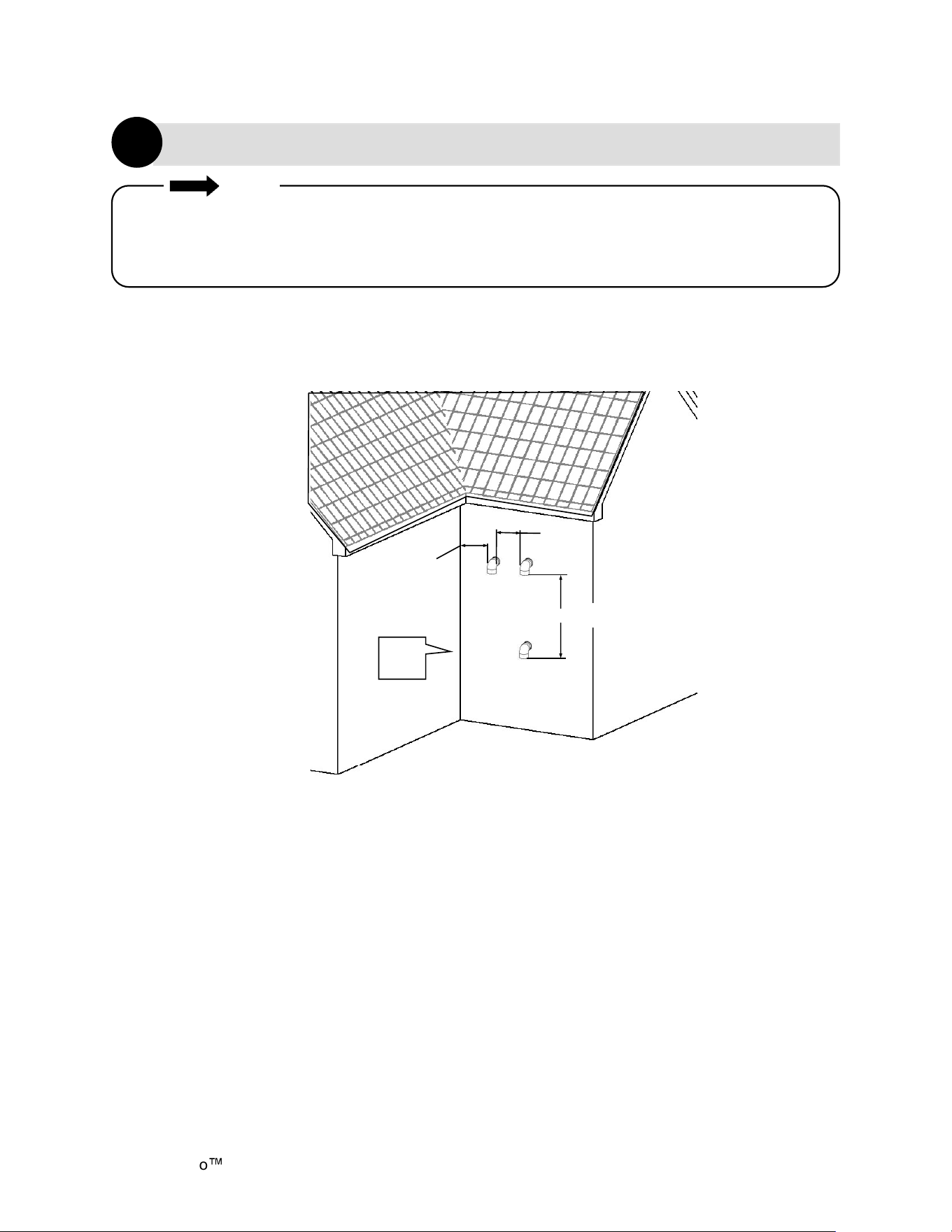
All terminations (horizontal and/or vertical)
must terminate 12 in. (0.30 m) above grade or
anticipated snow level.
Combustion air and exhaust vent directly through
a single concentric connection. Hot exhaust exits
through the interior tube, while combustion air
enters through the outer layer.
Concentric Pipe Termination Clearances
Direct Vent (Concentric Pipe)
1
Concentric Pipe Overview
Combustion
air
Exhaust
Combustion
air
Figure 15
60 in. (1.52 m)
Between terminals at different levels
Note: 24 in. (0.61 m)
to wall or parapet
Figure 17
Between terminals at same level
12 in. (0.30 m)
Figure 18
Inside
Corner
12 in.
(0.30 m)
12 in.
(0.30 m)
Figure 16
60 in.(1.52 m)
vertically
between
terminals
Demand Duo
H-Series with SENSEI CX Installation Instructions 22
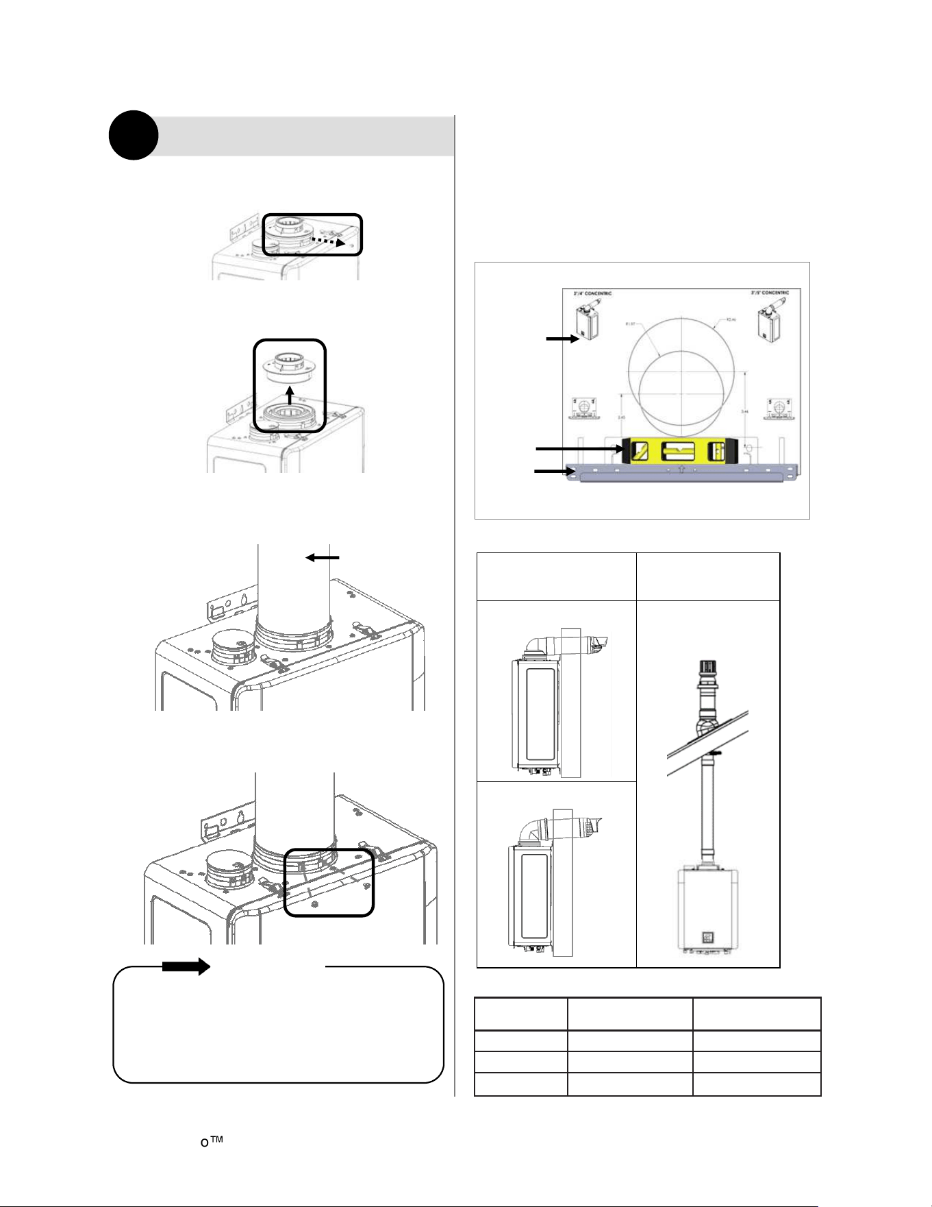
Direct Vent (Concentric Pipe)
1
1. Remove and discard screw from concentric
flue connection.
2. Remove exhaust adapter ring (discard for
concentric venting configurations.)
3. Install the concentric vent. Ensure it is
properly seated.
4. Secure the vent pipe to the concentric
flue connection with
the supplied screws.
If venting behind the unit through an exterior
wall, align the wall mounting bracket template
(located in literature bag) to the wall and follow
instructions on the template for appropriate vent
hole location. Use a level to make sure the wall
mounting bracket is even and level.
Table 8. Concentric Pipe: Maximum Vent Length
Install the venting termination according to the
diagrams and instructions in this manual.
Slope the venting 1/4 in. per foot (21 mm per
meter) toward the appliance according to the
vent manufacturer’s installation instructions.
Dispose of condensate per local codes.
IMPORTANT
Figure 20
Figure 19
Vent Sizes
2 in / 4 in
(51 mm/100 mm)
3 in / 5 in
(76 mm/125 mm)
Vent Lengths 75 ft (23 m) 150 ft (46 m)
45° Elbow 3 ft (1 m) 2.5 ft (0.7 m)
90° Elbow 6 ft (2 m) 5 ft (1.5 m)
Figure 23
Level
Wall
Mounting
Bracket
Wall
Mounting
Bracket
Template
Figure 21
Concentric
vent
Figure 22
Horizontal Wall
Terminations
Vertical Roof
Terminations
2 in. x 4 in. 2 in. x 4 in. and
3 in. x 5 in.
3 in. x 5 in.
Table 7. Terminations
Mount Concentric Pipe Through
Wall
Demand Duo H-Series with SENSEI CX Installation Instructions 23
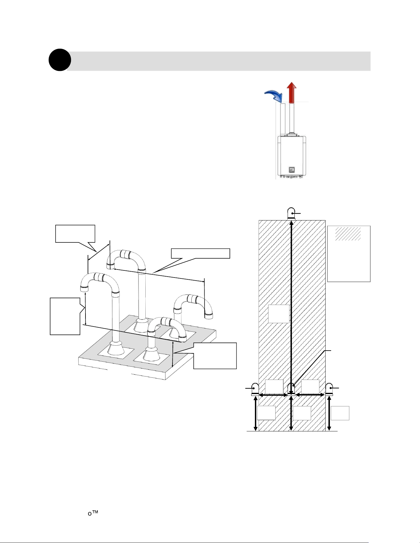
Twin Pipe Termination Clearances
Direct Vent (Twin Pipe)
1
Combustion air and exhaust vent directly through
separate penetrations.
Twin Pipe Overview
Twin Pipe Vertical Termination
of Multiple Water Heaters
12 in. (0.30 m) minimum
12 in.
(0.30 m)
minimum
above
combustion
air opening
Roof
12 in. (0.30 m)
above grade or
anticipated snow
level
12 in. (0.30 m)
minimum
Combustion
Air
Exhaust
Figure 24
Figure 25
Intake
Ground/Grade/Snow Level
60 in.
min
Indicates
area in
which intake
cannot be
located.
12 in.
min
12 in.
min
12 in.
min
12 in.
min
12 in.
min
Intake
Exhaust
Intake
Demand Duo
H-Series with SENSEI CX Installation Instructions 24
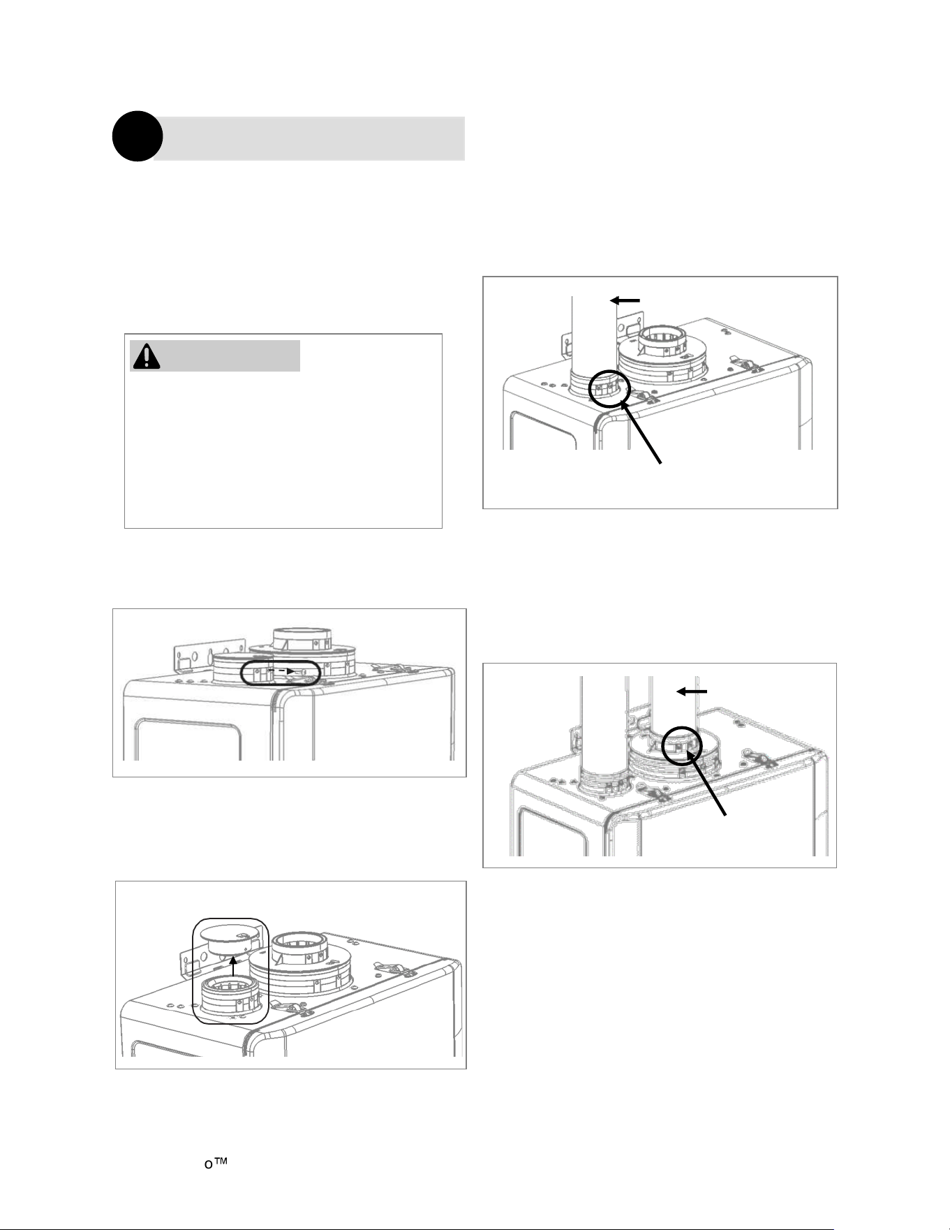
Direct Vent (Twin Pipe)
1
The water heater is equipped with a 2 in.
(51 mm) pipe connection. With the use of a
pipe reducer, installers can use a 3 in.
(76 mm) pipe for the
Intake air and
exhaust. In this case, a 2 in./3 in. pipe
reducer should be installed as close as
possible to the water heater.
1. Remove and discard the screw from
the intake air vent connection.
2. Remove and discard the intake air vent
cap.
4. Install the exhaust vent pipe. Ensure it
is properly seated.
Secure the exhaust vent pipe to the
exhaust adapter ring with the supplied
screws.
3. Install the intake air vent pipe. Ensure it
is properly seated.
Secure the intake air vent pipe to the
intake air vent connection with the
supplied screws.
DO NOT apply PVC glues, solvents, or
cleaners to the water heater’s intake air or
exhaust gasket connections. Failure to
correctly assemble the components
according to these instructions may result
in property damage, personal injury, or
death.
WARNING
Figure 26
Figure 27
Supplied
screws
Exhaust
Supplied
screws
Figure 29
Figure 28
Intake Air Vent Pipe
Demand Duo H-Series with SENSEI CX Installation Instructions 25
Direct Vent (Twin Pipe)
1
Twin Pipe Example Vent Applications
Table 10. Twin Pipe Maximum Equivalent Length
Twin Pipe Maximum Vent Length
Slope horizontal exhaust 1/4 in. per foot (21 mm per meter) towards the water heater. DO NOT
slope intake air pipe towards the water heater.
This configuration requires the use of a
Concentric Vent
Termination
This configuration requires the use of a
Concentric Vent Termination
2 in. or 3 in. PVC/ CPVC
IPEX/ Royal
Concentric
Side Wall Termination
Configuration
2 in. or 3 in. PVC/CPVC
IPEX/ Royal Concentric
Vertical Termination
Configuration
2 in. or 3 in. Schedule
40 PVC/CPVC or ABS
Snorkel Termination
Configuration
2 in. or 3 in.
Schedule
40 PVC/CPVC
or ABS
Standard upside down “U”
Vertical Termination
Configuration
2 in. or 3 in. Schedule
40 PVC/CPVC or ABS
Elbow
or Tee Side Wall
Termination Configuration
2 in. or 3 in. Schedule
40 PVC/CPVC or ABS
Tee
Vertical Termination
Configuration
2 in. or 3 in.
PVC
Low Profile
Termination
Configuration
Exhaust and
intake air
MUST NOT be
brought
together into a
single PVC
pipe using
a pipe fitting.
Intake air
Single
pipe
Exhaust
WARNING
Table 9
Vent Sizes 2 in. (51 mm) 3 in. (76 mm)
Vent Lengths 75 ft (23 m) 150 ft (46 m)
45° Elbow 3 ft (1 m) 2.5 ft (0.7 m)
90° Elbow 6 ft (2 m) 5 ft (1.5 m)
Demand Duo
H-Series with SENSEI CX Installation Instructions 26
Canadian Installaons
(CSA B149.1)
U.S. Installaons
(ANSI Z223.1 /NFPA 54)
Ref Descripon
Other than direct vent
(Outdoor unit and/or Room Air)
Other than direct vent
(Outdoor unit and/or Room Air)
A
Clearance above grade, veranda, porch, deck, or
balcony
12 in. (30 cm) 12 in. (30 cm)
B Clearance to window or door that may be opened 36 in. (91 cm)
4 (1.2 m) below or to side of opening;
1 (300 mm) above opening
C Clearance to permanently closed window * *
D
Vercal clearance to venlated sot, located above
the terminal within a horizontal distance of 2 (61
cm) from the center line of the terminal
* *
E Clearance to unvenlated sot * *
F Clearance to outside corner * *
G Clearance to inside corner * *
H
Clearance to each side of center line extended above
meter/regulator assembly
* *
I Clearance to service regulator vent outlet
Above a regulator within 3 (91 cm)
horizontally of the vercal center line of
the regulator vent outlet to a maximum
vercal distance of 15 (4 m)
*
J
Clearance to non-mechanical air supply inlet to
building or the combuson air inlet to any other
appliance
36 in. (91 cm)
4 (1.2 m) below or to side of opening;
1 (300 mm) above opening
K Clearance to a mechanical air supply inlet 6 (1.83 m)
3 (91 cm) above if within 10
(3 m) horizontally
L
Clearance above paved sidewalk or paved driveway
located on public property
7 (2.13 m) [1] *
M Clearance under veranda, porch, deck, or balcony 12 in. (30 cm) [2] *
Non-Direct Vent (Room Air)
2
AIR SUPPLY INLET
VENT TERMINAL
AREA WHERE TERMINAL
X
V
SNOW
TERMINATION
Clearance in
Ref. A also
applies to
anticipated
snow line
Clearance to opposite wall is 24 in. (60 cm).
[1] A vent shall not terminate directly above a sidewalk or paved driveway
that is located between two single family dwellings and serves both
dwellings.
[2] Permied only if veranda, porch, deck, or balcony is fully open on a
Clearances are in accordance with local installaon codes and
the requirements of the gas supplier. (Dégagement conforme
aux codes d’installaon locaux et aux exigences du foumisseur
de gaz.)
Table 12
Table 11
Figure 30: Room Air Termination Clearances
Demand Duo H-Series with SENSEI CX Installation Instructions 27
Exhaust Termination Clearances for Internal (Indoor) Room Air Applications
Non-Direct Vent (Room Air)
2
• Installation of Non-Direct Vent (Room Air) must use listed category IV venting.
• All terminations (horizontal and/or vertical) must terminate 12 in. above grade or anticipated
snow level.
NOTE
60 in.
12 in.
12 in.
(0.30 m)
Inside
Corner
(1.52 m) vercally between terminals
Figure 31
Demand Duo
H-Series with SENSEI CX Installation Instructions 28
For applications containing corrosive indoor air,
this appliance must be installed as direct vent.
DO NOT use room air in applications where
combustion air contains acid forming chemicals
such as sulfur, fluorine and chlorine. These
chemicals have been found to cause rapid
damage and decay and can become toxic when
used as combustion air in gas appliances. Such
chemicals can be found in, but not limited to
bleach, ammonia, cat litter, aerosol sprays,
cleaning solvents, varnish, paint and air
fresheners. Do not store these products or similar
products in the vicinity of this water heater.
Unconfined Space
An unconfined space is defined in National Fuel
Gas Code, ANSI Z223.1/NFPA 54 as “a space
whose volume is not less than 50 cubic feet per
1000 Btu/hr (4.8 m3 per kW per hour) of the
aggregate input rating of all appliances installed
in that space. Rooms communicating directly with
the space in which the appliances are installed,
through openings not furnished with doors, are
considered a part of the unconfined space.” If the
“unconfined space” containing the appliance(s) is
in a building with tight construction, additional
outside air may be required for proper operation.
Outside air openings should be sized the same
as for a confined space.
This water heater requires adequate
combustion air for ventilation and dilution of flue
gases. Failure to provide adequate combustion
air can result in unit failure, fire, explosion,
serious bodily injury or death. Use the following
methods to ensure adequate combustion air is
available for correct and safe operation of this
water heater.
Combustion Air
Non-Direct Vent (Room Air)
2
Combustion air must be free of corrosive
chemicals. Do not provide combustion air from
corrosive environments. Appliance failure due
to corrosive air is not covered by warranty.
IMPORTANT
If ducts are used, the cross sectional area of
the duct must be greater than or equal to the
required free area of the openings to which
they are connected.
NOTE
Confined Space
A confined space is defined in the National Fuel
Gas Code, ANSI Z223.1/NFPA 54 as "a space
whose volume is less than 50 cubic feet per
1000 Btu/hr (4.8 m3 per kW per hour) of the
aggregate input rating of all appliances installed
in that space." Examples include a small room,
closet, alcove, utility room, etc. A confined space
must have two combustion air openings. Size
the combustion air openings based on the BTU
input for all gas utilization equipment in the
space and the method by which combustion air
is supplied.
Using Indoor Air For Combustion:
When using air from other room(s) in the
building, the total volume of the room(s) must be
of adequate volume (Greater than 50 cubic feet
per 1000 Btu/hr). Combustion air openings
between joining rooms must have at least
1 square inch of free area for each 1000 Btu/hr,
but not less than 100 square inches each.
Using Outdoor Air For Combustion
Outdoor air can be provided to a confined space
through two permanent openings, one
commencing within 12 in. (0.30 m) of the top and
one commencing within 12 in. (0.30 m) of the
bottom, of the confined space. The openings
shall communicate to the outside by one of two
ways.
When communicating directly with the outdoors
through horizontal ducts, each opening shall
have a minimum free area of 1 in
2
/2000 Btu/hr
(1100 mm
2
/kW) of total input rating of all
appliances in the confined space.
WARNING
Demand Duo H-Series with SENSEI CX Installation Instructions 29
TO PREVENT POSSIBLE PERSONAL INJURY
OR DEATH DUE TO ASPHYXIATION, COMMON
VENTING WITH OTHER MANUFACTURER’S
INDUCED DRAFT APPLIANCES IS NOT
ALLOWED.
Location
To maintain proper circulation of combustion air
two permanent openings (one upper, one lower)
must be positioned in confined spaces. The
upper shall be within 12 in. (0.30 m) of the top of
the confined space and the lower opening shall
be within 12 in. (0.30 m) of the bottom of the
confined space. Openings must be positioned as
to never be obstructed.
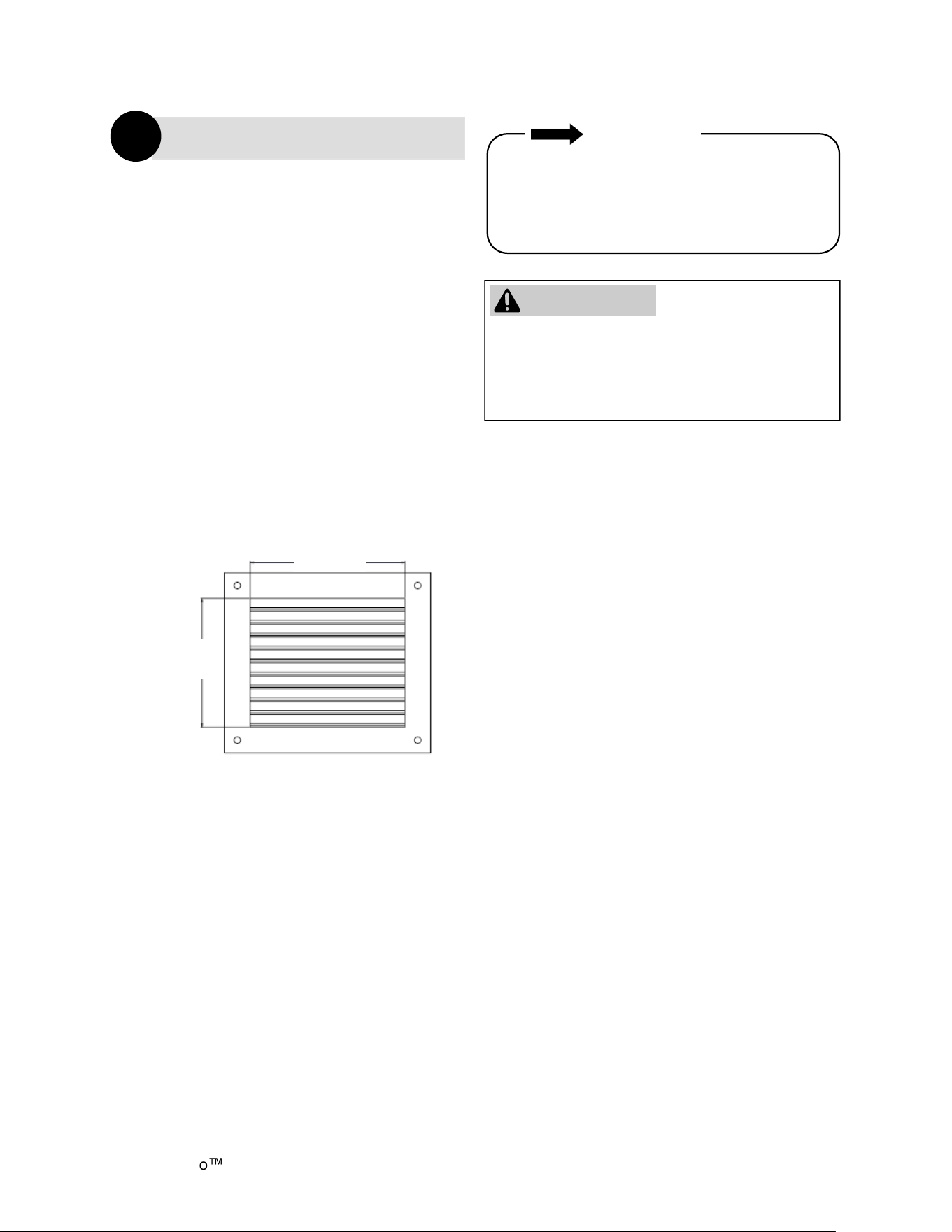
Louvers and Grills
When sizing the permanent opening
consideration must be taken for the design of
the louvers or grills to maintain the required free
area required for all gas utilizing equipment in
the space. If the free area of the louver or grill
design is not available, assume wood louvers
will have 25% free area and metal louvers or
grills will have 75% free area. Under no
circumstance should the louver, grill or screen
have openings smaller than 1/4 in.
Free Area = Height x Length x % Free Area
Wood: 18 in. x 24 in. x 0.25 = 108 in.
2
Metal: 18 in. x 24 in. x 0.75 = 324 in.
2
Non-Direct Vent (Room Air)
2
Combustion Air (Continued)
Combustion air provided to the appliance
should not be taken from any area of the
structure that may produce a negative
pressure (i.e. exhaust fans, powered
ventilation fans).
IMPORTANT
24 in.
(600 mm)
18 in.
(450 mm)
Figure 32
WARNING
Demand Duo
H-Series with SENSEI CX Installation Instructions 30
Non-Direct Vent (Room Air)
2
Exhaust
Vent termination per ANSI Z223.1/NFPA 54. For
clearances not specified in ANSI Z223.1/NFPA 54,
clearances are in accordance with local installation
codes and the requirements of the gas supplier.
Figure 33
Demand Duo H-Series with SENSEI CX Installation Instructions 31
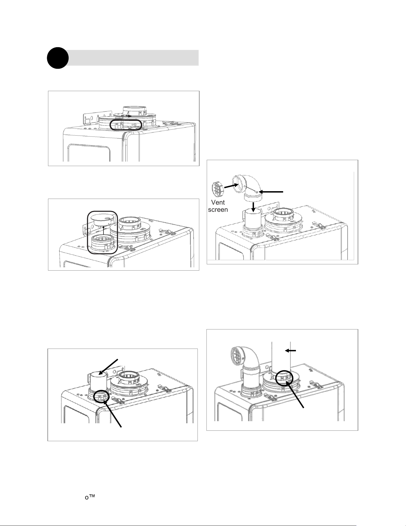
Non-Direct Vent (Room Air)
2
1. Remove and discard screw from
combustion air vent connection.
2. Remove and discard the combustion air
vent cap.
3. Install the intake air pipe. Ensure it
is properly seated.
Secure the intake air pipe to the
combustion air vent connection with
the supplied screws.
4. Place the vent screen or room air screen
inside elbow and secure with the supplied
screw. Use the room air screen for
environments where room air is dusty.
Notes:
•
2 in vent screen supplied with
water heater.
•
Room air screen is available as
an accessory.
5. Install the exhaust vent pipe.
Ensure it is properly seated.
Secure the exhaust vent pipe to the
exhaust adapter ring with the supplied
screws.
Figure 35
Figure 34
Figure 36
Intake Air Pipe
Supplied screws
Vent
screen
Supplied screw
Elbow
Figure 37
Figure 38
Exhaust vent
Supplied
screws
Demand Duo
H-Series with SENSEI CX Installation Instructions 32
Non-Direct Vent (Room Air)
2
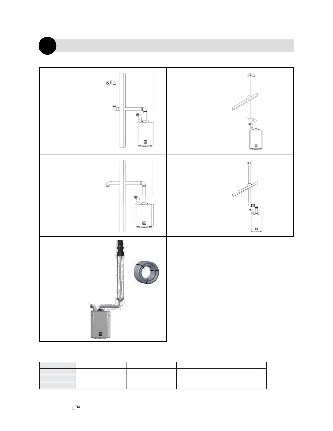
Table 13: Room Air: Example Vent Applications
2 in. or 3 in.
Schedule 40
PVC/CPVC or
ABS Snorkel
Termination
Configuration
2 in. or 3 in.
Schedule 40
PVC/CPVC or
ABS Elbow or
Tee Side Wall
Termination
Configuration
2 in. or 3 in.
Schedule 40
PVC/CPVC or
ABS Standard
Upside Down
“U” Vertical
Termination
configuration
2 in. or 3 in.
Schedule 40
PVC/CPVC or
ABS Tee
Vertical
Termination
Configuration
Slope horizontal exhaust 1/4 in. per foot
(21 mm per meter) towards the water
heater.
Room Air: Maximum Vent Length
Table 14. Room Air Maximum Equivalent Length
Vent Sizes 2 in. (51 mm) 3 in. (76 mm) 3 in. (76 mm) Ubbink Flex
Vent Length 75 ft (23 m) 150 ft (46 m) 50 ft. (15 m)
45° Elbow 3 ft (1 m) 2.5 ft (0.7 m)
90° Elbow 6 ft (2 m) 5 ft (1.5 m)
Ubbink flexible
venting approved for
vertical
non-direct vent
(room air)
applications only.
Refer to the flex vent
manual for further
details.
PP Flex
Venting
Demand Duo H-Series with SENSEI CX Installation Instructions 33
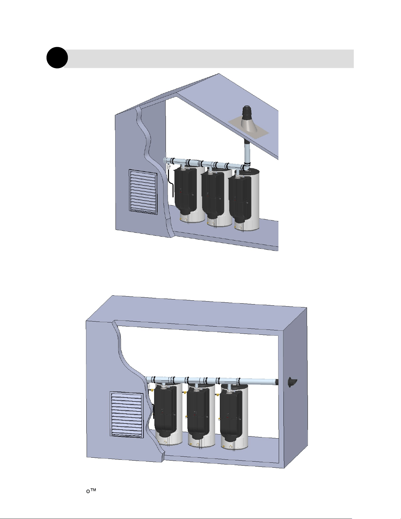
When installing Common Vent, follow these
guidelines:
• Vent system must be supported according to
the vent manufacture’s installation
instructions.
• Venting should be as direct as possible with
a minimum number of fittings.
• The common vent system must only be
installed by a trained and qualified
professional.
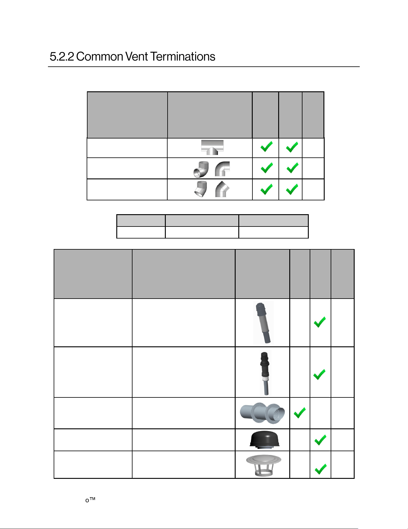
Common Vent Termination Clearances
• Vent termination per ANSI Z223.1/NFPA 54.
For clearances not specified in ANSI Z223.1/
NFPA 54, clearances are in accordance with
local installation codes and the requirements
of the gas supplier.
Common venting allows multiple Rinnai Tankless
Water Heaters to share the same vent system.
Rinnai water heaters can only be common vented
with Schedule 40 PVC/CPVC or with the Rinnai
certified common vent system.
DO NOT obstruct combustion air flow or
exhaust gas flow in the venting system.
DO NOT install the water heater in an area
with negative air pressure.
DO NOT combine the common vent system
with existing vents, chimneys, or vent pipes
connected to other water heaters, boilers or
appliances.
DO NOT common vent different Rinnai
models in a single common vent system.
DO NOT use cellular core PVC/CPVC,
Radel or galvanized materials.
DO NOT combine vent components from
different manufacturers.
DO NOT slope the combustion air pipe
toward unit. Failure to comply with this
warning could result in property damage,
personal injury, or death.
DO NOT apply PVC/CPVC glues, solvents,
or cleaners to the tankless water heater’s
intake or exhaust gasket connections.
Failure to correctly assemble the
components according to these instructions
may result in property damage, personal
injury, or death.
Common Vent
(Indoor Units Only. Direct Vent and
Non-Direct/Room Air Vent)
3
General Guidelines
• Use only the materials listed in this manual
for vent, air intake pipe, and fittings. Failure to
comply with this warning could result in
property damage, personal injury, or death.
• When cutting vent components, ensure that
the cuts are straight.
• Chamfer and deburr all edges before
installing the components.
• Vent joints must not leak. Confirm gas tight
connections of every vent joint.
• Before operating the water heater(s), ensure
vent system is clean and free of debris.
WARNING
Example: Rinnai Common Venting
Example: Schedule 40 PVC/CPVC
Common Vent
Figure 39
Demand Duo
H-Series with SENSEI CX Installation Instructions 34
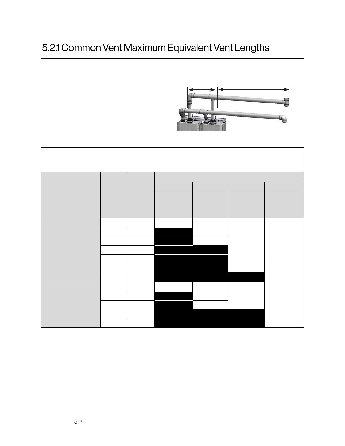
For the table below:
• Header is the main vent pipe into which
several vents connect
• Vent Length is the distance from the end of
the header to the vent termination.
• Maximum vent length starts at the end of the
header system.
• Use 10 ft (3 m) as equivalent vent length for
90° elbows.
Common Vent Maximum Equivalent Vent Length
Rinnai Common Vent System or Schedule 40 PVC/CPVC
Water Heater
Model
# Water
Heaters
Max
System
BTU/HR
HEADER DIAMETER
3 in. 4 in. 6 in.
3 in.
Vent
Diameter
4 in.
Vent
Diameter
6 in.
Vent
Diameter
6 in.
Vent
Diameter
CX199i
(REU-N3237FFC-US)
2 398,000 65
150
150
150
3 597,000
4 796,000
65
5 995,000
6 1,194,000
7 1,393,000 70
8 1,592,000
CX160i
(REU-N2530FFC-US)
2 320,000 90 150
150
150
3 480,000
100
4 640,000 65
5 800,000
6 960,000
Figure 40
Header
Vent length
Table 15
Demand Duo H-Series with SENSEI CX Installation Instructions 35
Manufacturer Phone Web Site
Ubbink 800-621-9419 www.rinnai.us
Tee
10
90° Elbow
10
45° Elbow
5
Product
Descripon
Horizontal
Vertical
Equivalent
Length (ft)
Diagram
790096
790095
CVent Roof Termination 6 in.
CVent Roof Termination 4 in.
5
790125 CVent Roof Termination 3 in.
5
790094
790093
90124
CVent Wall Terminal Kit 6 in.
CVent Wall Terminal Kit 6 in.
CVent Wall Terminal Kit 6 in.
5
780061
780060
Intake Rain Cap 6 in.
Intake Rain Cap 4 in.
N/A
790098
790097
Exhaust Flue Rain Cap 6 in.
Exhaust Flue Rain Cap 4 in.
N/A
Diagram
Horizontal
Vertical
Equivalent
Length (ft)
Part Number
Product
Description
Rinnai Common Vent Terminations (Ubbink C-Vent)
Various 3 in., 4 in. and 6 in. Schedule 40 PVC/CPVC Terminations
Table 17
Table 16
Demand Duo
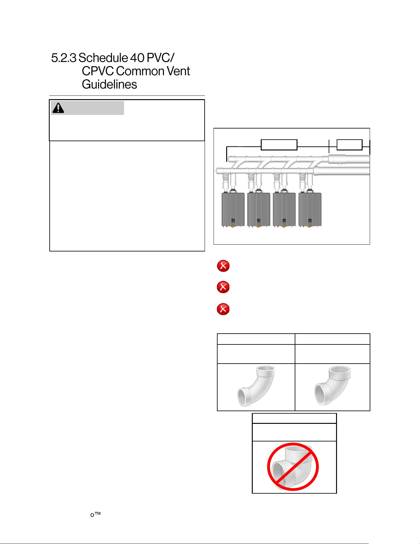
H-Series with SENSEI CX Installation Instructions 36
When installing PVC/CPVC Common Vent,
follow these guidelines:
• Avoid sharp bends or tees in the vent
system. These vent components create
additional restrictions that could reduce
performance of the water heaters.
• PVC combustion air and exhaust should
terminate with elbow or tee pointing down.
This will stop unwanted moisture from
entering the vent system.
• Fire rated penetrations shall be fire stopped.
Contact your vent supplier or local firestop
manufacturer for appropriate firestop
methods.
• Examine all vent components for damage
prior to installation.
• PVC/CPVC vent systems must be free to
expand and contract. Refer to the vent
manufacturer’s installation instructions for
appropriate support methods.
• PVC/CPVC venting must include unrestricted
vent movement through walls, ceilings, and
roof penetrations.
• Use only PVC/CPVC primer and cement
approved for use by the vent manufacturer.
• Keep solvents away from heat, sparks,
flames and all other sources of ignition.
• Do not solder, cut or weld until all vapors
have dissipated.
• PVC solvents are heavier than air causing
them to settle at low points of the system.
• Before using PVC solvent
− Disconnect power to the water heater.
− Remove the front cover of the water
heater.
− Ensure areas around the water heater
and PVC venting are all well ventilated.
− Allow all vapors to dissipate before
applying power to the system or
introducing any other source of ignition.
PVC solvents (primer
and glue) can be
extremely flammable. Vapors may cause a
flash fire or explosion resulting in property
damage, personal injury or death.
DO NOT
DO NOT mix vent pipe, fittings or joining
methods from different vent manufacturers.
DO NOT attempt to repair damaged vent.
Damaged vent components must be
replaced.
DO NOT use short radius elbows in the
common vent system.
ACCEPTABLE ACCEPTABLE
90° Elbows, Long
Sweep
90° Elbows, Short
Sweep
• Refer to vent manufacturer’s installation
instructions for proper joint assembly
procedures and products.
• PVC/CPVC common venting should include
a condensate drain and trap between the
header and vent length. Condensate trap
must include a loop that can hold 6 in.
(15 cm) of water. See “PVC/CPVC Common
Vent Installation” illustration on this page.
NOT ACCEPTABLE
90° Elbows,
Close Turn
WARNING
Table 18
HEADER VENT
PVC/CPVC Common Vent Installation
Figure 41
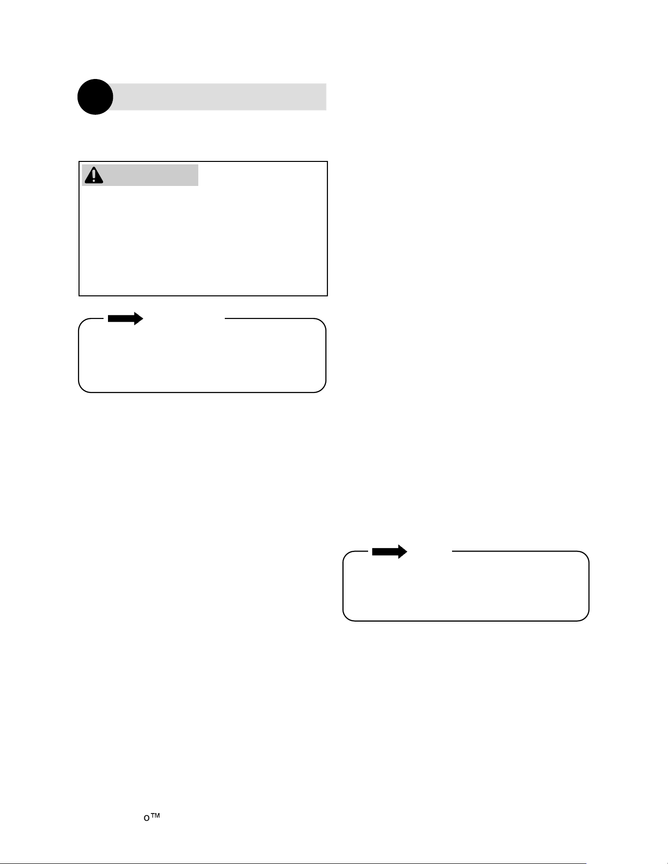
Demand Duo H-Series with SENSEI CX Installation Instructions 37
Water discharged from the pressure relief valve
could cause severe burns instantly or death from
scalds.
WARNING
An approved pressure relief valve (preinstalled) is
required by the American National Standard
(ANSI Z21.10.3) for all water heating systems
and shall be accessible for servicing.
DO NOT
• Do not plug the relief valve and do not install
any reducing fittings or other restrictions in the
relief line. The relief line should allow for
complete drainage of the valve and the line.
• Do not place any other type valve or shutoff
device between the relief valve and the water
heater.
Install the Temperature-Pressure Relief (T&P)
Valve according to these instructions.
The tank portion of this system is provided with a
combination T&P relief valve. For safe operation
of the water heater, the relief valve(s) must not be
removed from its designated point of installation
or plugged.
An approved T&P relief valve is required by the
American National Standard (ANSI Z21.10.3) for
all water heating systems, and shall be
accessible for servicing.
DO NOT
• Do not plug the T&P relief valve and do not
install any reducing fittings or other restrictions
in the relief line. The relief line should allow for
complete drainage of the T&P relief valve and
the line.
• Do not place any other type valve or shut off
device between the relief valve and the water
heater.
• Do not pipe T&P relief valve, pressure relief
valve, and/or condensate drain together into a
common pipe.
MUST DO
• The T&P valve must comply with the standard
for Relief Valves and Automatic Gas Shutoff
Devices for Hot Water Supply Systems ANSI
Z21.22 and /or the standard Temperature,
Pressure, Temperature and Pressure Relief
Valves and Vacuum Relief Valves, CAN1-4.4.
Topics in this section
• Pressure Relief Valve Requirements
• Temperature - PRV Requirements
• Connect the Water Heater to the Water
Supply
• Typical Installations
• Piping Diagram for Basic Installations
• Piping Diagram for Multiple Unit Installations
• The relief valve is installed near the tankless
hot water outlet.
INFORMATION
If a relief valve discharges periodically, this may
be due to thermal expansion in a closed water
supply system. Contact the water supplier or
local plumbing inspector on how to correct this
situation. Do not plug the relief valve.
MUST DO
• The relief valve must comply with the standard
for Relief Valves and Automatic Gas Shutoff
Devices for Hot Water Supply Systems ANSI
Z21.22 and /or the standard Temperature,
Pressure, Temperature and Pressure Relief
Valves and Vacuum Relief Valves, CAN1-4.4.
• The pressure relief valve must be rated up to
150 psi and to at least the maximum Btu/hr of
the appliance.
• The discharge from the pressure relief valve
should be piped to the ground or into a drain
system per local codes.
• The pressure relief valve must be manually
operated once a year to check for correct
operation.
Demand Duo
H-Series with SENSEI CX Installation Instructions 38
Water connections to the Commercial Hybrid
System should follow all state and local plumbing
codes.
If this is a standard installation, refer to section
“6.5 Piping Diagram for Basic Installations.”
1. Use of this layout should provide a
trouble-free installation for the life of the water
heater. Before making the plumbing
connections, locate the COLD water inlet and
the HOT water outlet.
• The COLD water inlet is a 1-1/2 in. MNPT
fitting on the lower portion of the tank
below the tankless unit. Install a shut-off
valve close to the water heater in the cold
water line.
• The HOT water outlet is a 1-1/2 in. MNPT
fitting located at the top of the tank.
• It is recommended that unions be
installed in the cold and hot water lines so
that the water heater can be easily
disconnected, if servicing is required.
2. When assembling the hot and cold piping,
use a good food grade pipe joint compound,
and ensure all fittings are tight. It is
imperative that open flame is not applied to
the inlet and outlet fittings, as heat will
damage or destroy the plastic lined fittings.
This will result in premature failure of the
fittings, which is not covered by the
warranty.
DO NOT OPERATE THIS WATER HEATER
UNLESS IT IS COMPLETELY FULL OF
WATER. To prevent damage to the water heater,
all air must be relieved from the system and a hot
water fixture must be flowing water before the
water heater is plugged in and turned on. To
ensure safe and effective operation of the water
heater, use the following filling procedure. To fill
the water heater:
1. Ensure the drain valve located at the bottom
of the tank is closed.
2. Open the nearest hot water fixture in the
plumbing system.
3. Open the cold water supply valve to the water
heater.
4. Keep the hot water fixture open until the tank
is filled and constant flow is obtained at the
fixture.
5. Check water heater connections and
plumbing system for damage or leaks.
Repair if needed.
NOTICE
DO NOT OPERATE THIS WATER HEATER
UNLESS IT IS COMPLETELY FULL OF
WATER.
• The T&P relief valve must be rated up to
150 psi and to at least the maximum Btu/hr of
the appliance.
• The discharge from the T&P relief valve should
be piped to the ground or into a drain system
to prevent exposure or possible burn hazards
to humans or other plant or animal life. Follow
local codes. Water discharged from the relief
valve could cause severe burns instantly,
scalds, or death.
• The T&P relief valve must be manually
operated once a year to check for correct
operation.
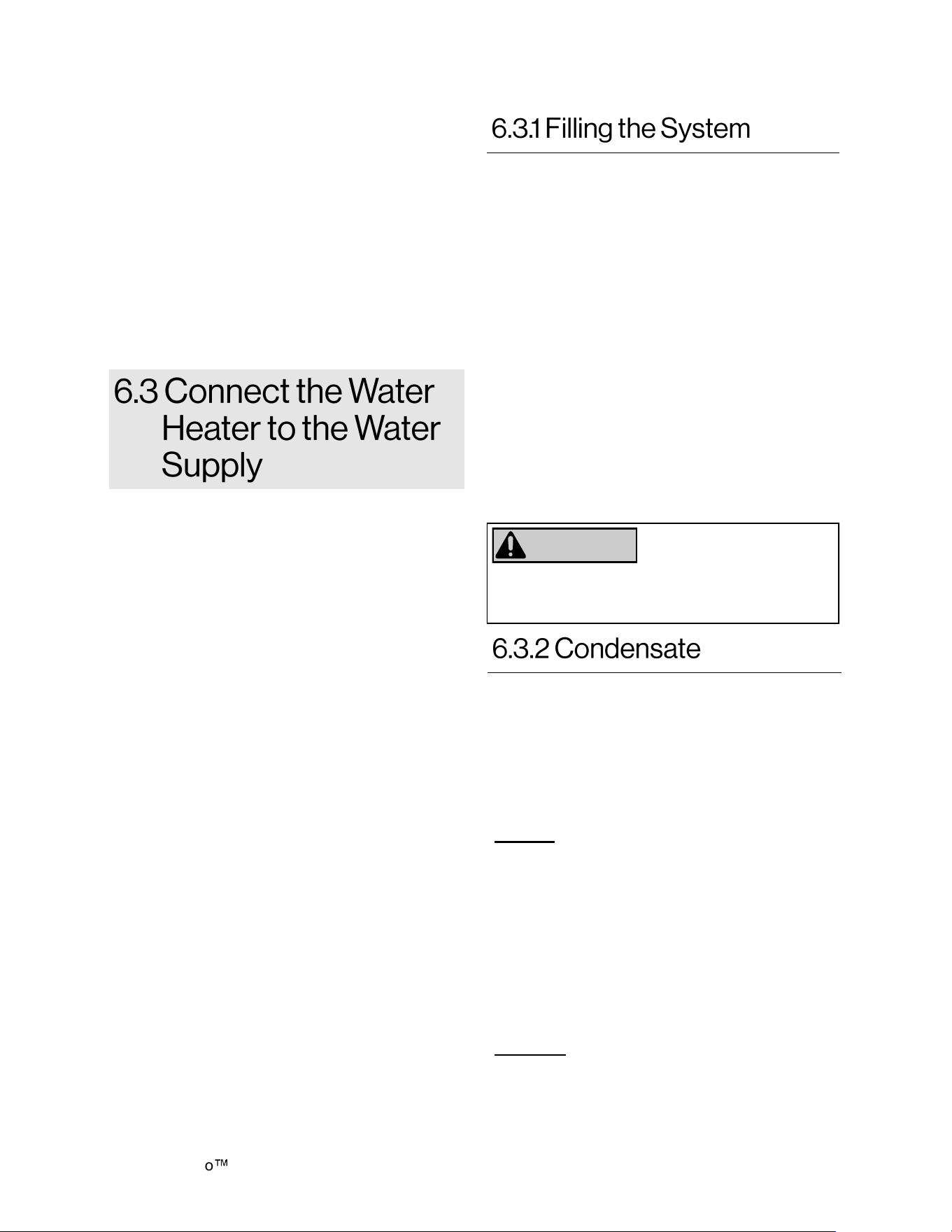
Condensate can form in the vent of high
efficiency direct vent appliances. Without proper
drainage, condensate will damage the heat
exchanger. Refer to Rinnai Tankless Water
Heater Installation and Operation Manual for
condensate guidelines.
To prevent condensate damage, follow these
instructions.
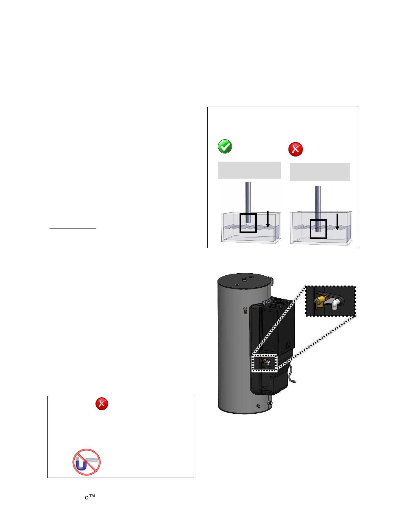
DO NOT
• Do not connect the condensate drain pipe
directly to the rain sewer.
• Do not connect the condensate drain line with
an air conditioning evaporator coil drain.
• Do not pipe condensate drain, temperature-
pressure relief valve, and/or pressure relief
valve together into a common pipe.
• Do not install an external condensate trap.
The tankless water heater has an integrated
condensate trap.
MUST DO
• Use only venting that is approved and
identified as acceptable for your particular
model.
Demand Duo H-Series with SENSEI CX Installation Instructions 39
• Slope the venting toward the appliance
according to the vent manufacturer’s
installation instructions.
• All condensate must drain and be disposed of
according to local codes.
• Use only corrosion resistant materials for the
condensate drain lines such as PVC pipe or
plastic hose.
• The condensate drain pipe (along its entire
length) must be at least the same diameter as
the drain line, (1/2 inch NPT).
• The end of the condensate drain pipe should
be open to the atmosphere. The end should
not be under water or other substances.
• To minimize freezing of the condensate, run
the condensate drain line through an interior
wall or between insulation and an interior wall.
• Ensure that condensate drain, PRV, and T&P
relief valve are piped separately to their own
dedicated drain lines.
• Dispose of condensate per local codes.
INFORMATION
• Water heaters have an integrated condensate
collector.
• The condensate drain pipe should be as short
as possible and have a downward pitch.
• If the condensate drain gets blocked, a
diagnostic code will display on the controller. If
this occurs, the condensate drain must be
cleaned.
• The condensate trap will automatically prime
(self-prime) during operation of the unit as
condensate forms. Condensate draining from
the unit indicates that the trap is full and that
there is no blockage in the condensate drain. It
is not necessary to add water to the
condensate trap.
• A condensate neutralizer kit (Part Number:
804000074) is available from Rinnai. The kit
allows condensate to flow through neutralizing
media that raises the pH of the condensate to
a level that will help prevent corrosion of the
drain and public sewer system.
A condensate line must be installed to the 1/2 in.
PVC elbow located at the left side of the lower
enclosure.
Condensate line must pitch toward the drain.
Air gap must be installed on the condensate line
to enable the condensate to drain.
CORRECT
Pipe open to
atmosphere
Pipe submerged
in water
NOT
CORRECT
Water
Level
Water
Level
• The end of the condensate drain pipe should
be open to the atmosphere. The end should
not be under water or other substances.
EXTERNAL TRAP
NOT REQUIRED
DO NOT
• DO NOT connect the condensate drain line
with an air conditioning evaporator coil drain.
• Water heaters have an integrated
condensate trap. DO NOT install an external
condensate trap.
Condensate
Drain
(1/2 in. PVC)
Figure 42
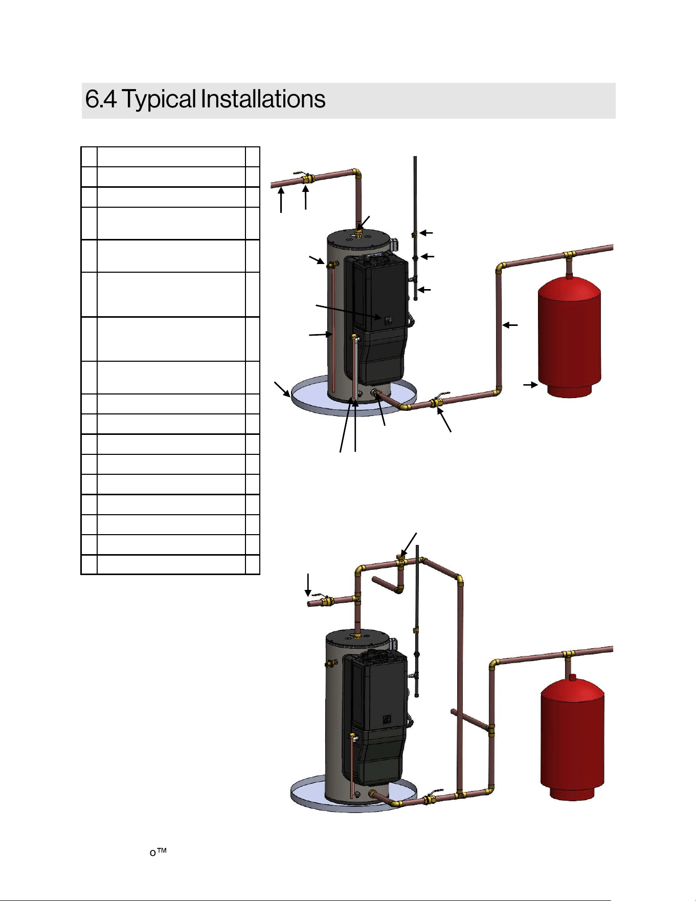
Demand Duo
H-Series with SENSEI CX Installation Instructions 40
A Hot Water Outlet *
B Hot Water Outlet Valve *
C Cold and Hot Unions *
D
Temperature-Pressure
Relief Valve
E
Operation Unit /
Temperature Control
F
Temperature-Pressure
Relief Valve Discharge Pipe
(do not cap, plug, or reduce)
*
G
Pressure Relief Valve
Discharge Pipe (do not cap,
plug, or reduce)
*
H
Condensate Discharge Pipe
(Must include air gap)
*
I Drain Pan *
J Thermal Expansion Tank *
K Gas Control Valve *
L Gas Union *
M Drip Leg (Sediment Trap) *
N Cold Water Supply Valve *
O Cold Water Supply *
P Non-Tempered Supply Line *
Q Thermostatic Mixing Valve *
* Field Supplied
Q
P
Figure 44
Mixing Valve Installation
Hot Water
Supply
A
B
C
D
O
N
J
E
I
F
M
L
K
G H
Figure 43
Cold Water Supply
Table 19
C
Hot
Water
Union
Cold
Water
Union
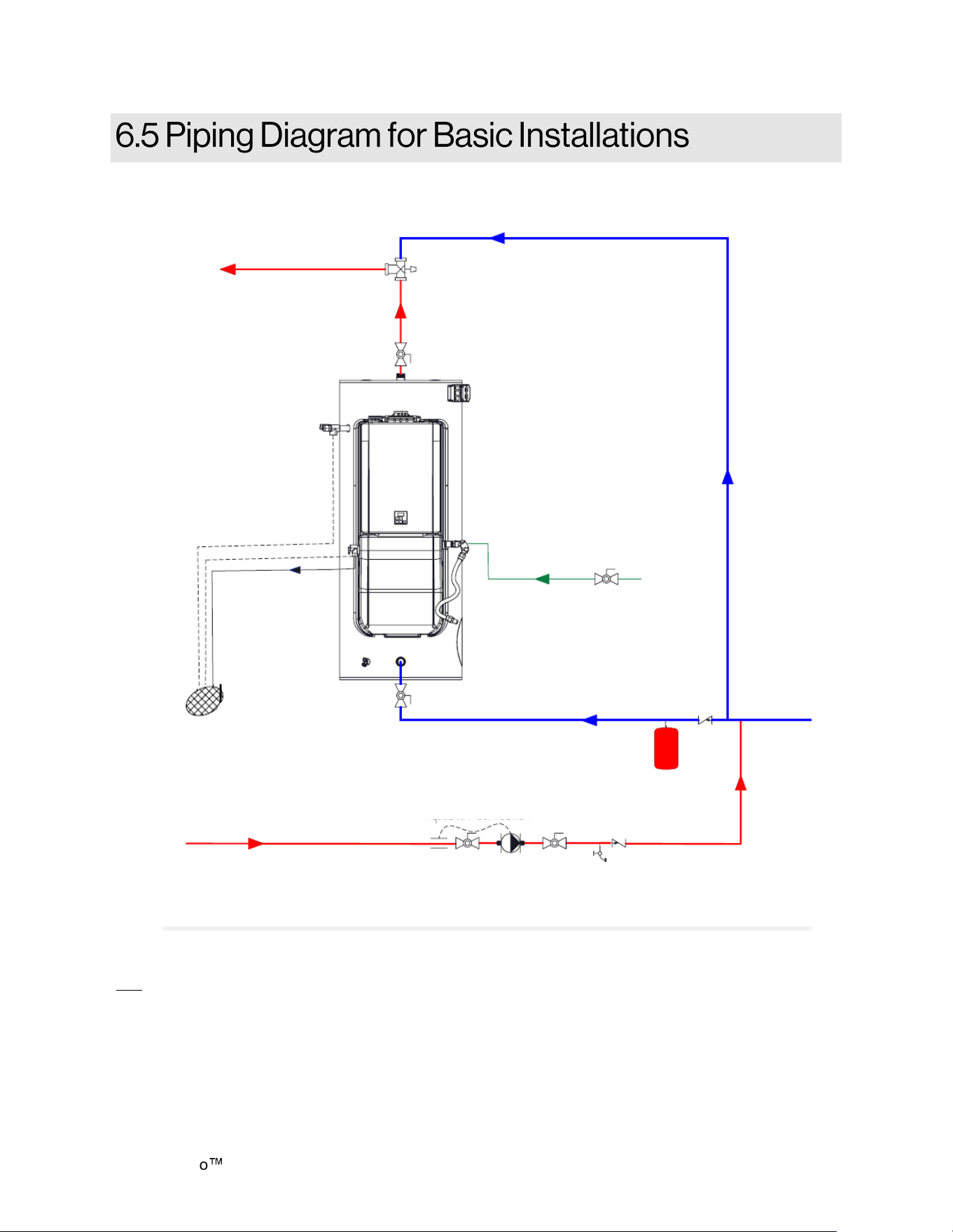
Demand Duo H-Series with SENSEI CX Installation Instructions 41
Commercial Hybrid Single Unit Circulation
Note:
Installation must conform to applicable code and all requirements listed in the installation manual. Balancing valves, equivalent piping, pressure
gauges, and temperature gauges are to be used as necessary to ensure proper flow between units.
Condensate piping shall be CPVC or PVC material and shall not be smaller than the drain connection on the appliance.
Components of condensate drainage shall be CPVC or PVC material. All components shall be selected for the pressure and temperature rating of
the installation.
Where the drain pipes from more than one unit are manifolded together for condensate drainage, the pipe or tubing shall be sized in accordance with
an approved method as dictated by local codes.
Condensate must be disposed of according to local codes.
Figure 45
Condensate Drain Line
Pipe T&P to Open Drain
Building Circulation Pump and
Aquastat
Gas Supply
Building Hot Water
Return Line (Optional)
Cold Water Supply
Tank
T&P
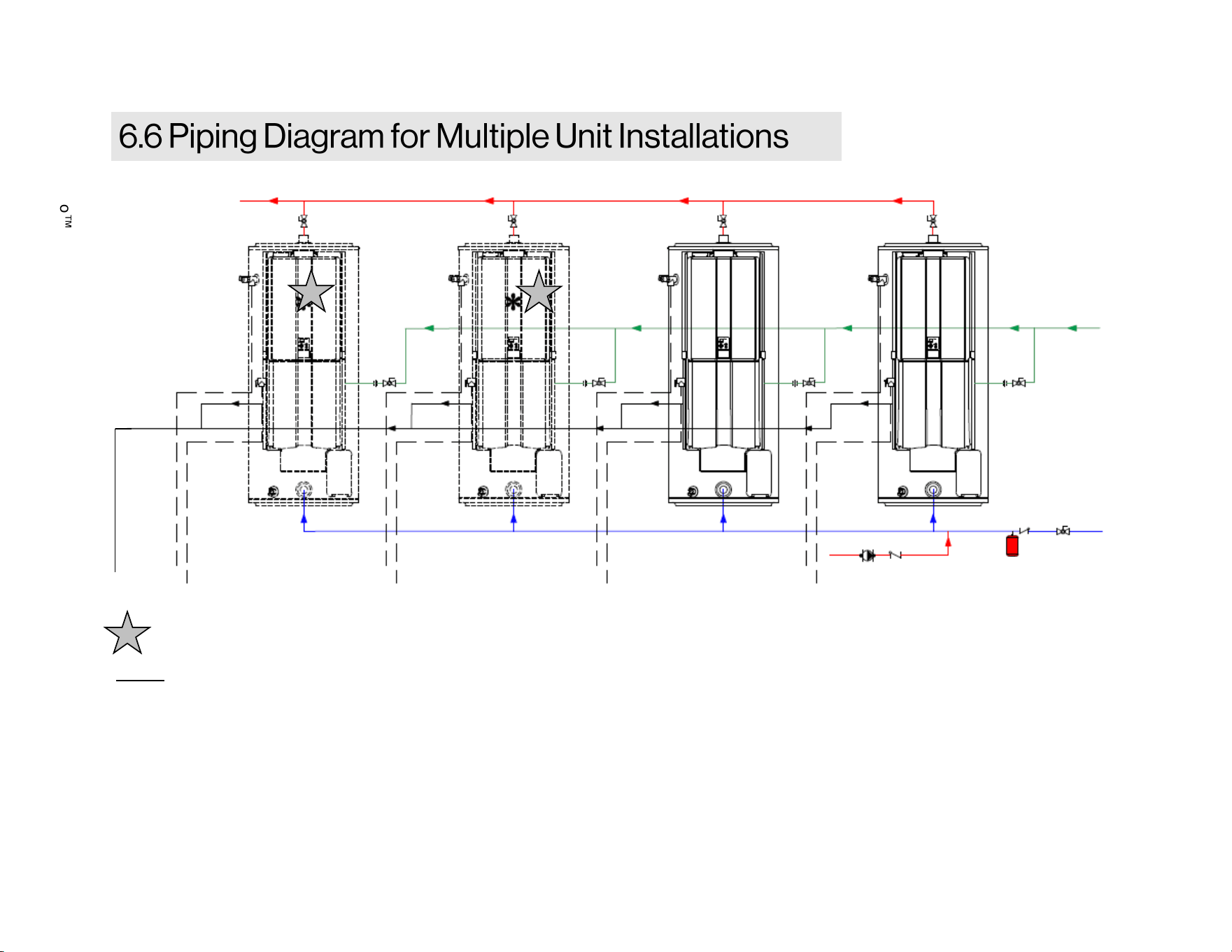
Demand Duo
H-Series with SENSEI CX Installation Instructions 42
Notes:
• Installation must conform to applicable code and all requirements listed in the installation manual. Balancing valves, equivalent piping,
pressure gages, and temperature gages are to be used as necessary to ensure proper flow between units.
• Condensate piping shall be CPVC or PVC material and shall not be smaller than the drain connection on the appliance.
• Components of the condensate drainage shall be CPVC or PVC material. All components shall be selected for the pressure and temperature
rating of the installation.
• Where the drain pipes from more than one unit are manifolded together for condensate drainage, the pipe or tubing shall be sized in
accordance with an approved method as dictated by local codes.
• Condensate must be disposed of according to local codes.
Additional units can be installed as illustrated.
HOT WATER SUPPLY LINE
CONDENSATE
DRAIN LINE
PIPE EACH T&P AND PRV TO OPEN DRAIN
BUILDING CIRCULATION PUMP AND
HOT WATER RETURN LINE
(OPTIONAL)
COLD WATER
SUPPLY
GAS SUPPLY
Figure 46
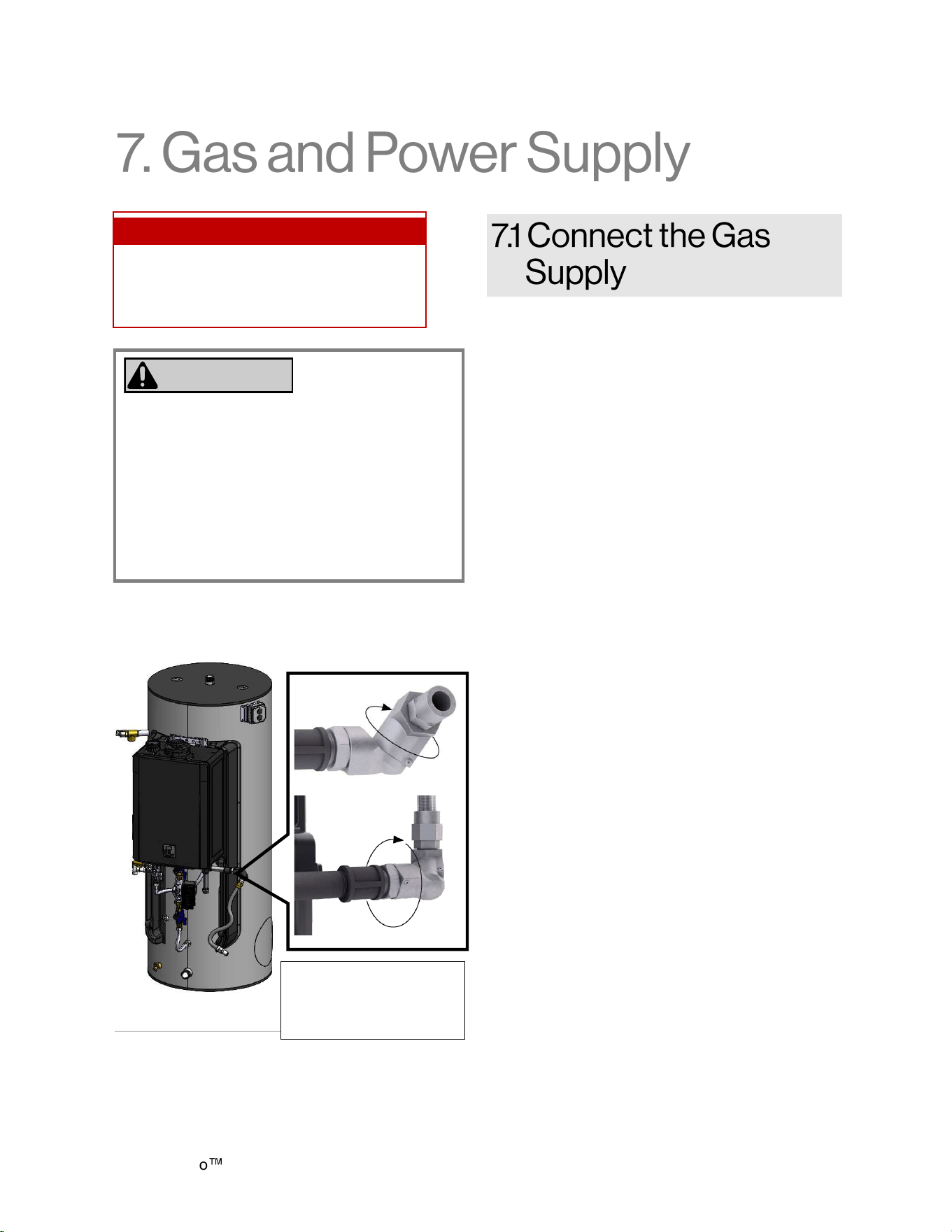
Demand Duo H-Series with SENSEI CX Installation Instructions 43
1. Install a manual gas control valve in the gas
supply line to the water heater. A union can
be used on the connection above the shut off
valve for the future servicing or disconnection
of the water heater (Figure 48 on the
following page).
2. Check the type of gas and gas supply
pressure before connecting the water heater.
If the water heater is not of the gas type that
the building is supplied with, DO NOT
connect the water heater. Contact the dealer
for the proper water heater to match the gas
type.
3. Check the gas supply pressure immediately
upstream at a location provided by the gas
company. Supplied gas pressure must be
within the limits shown in the Section “3.2
Specifications” with all gas appliances
operating. Before placing the appliance in
operation, all joints including the heater must
be checked for gas tightness by means of
soap, gas leak detector solution, or an
equivalent nonflammable solution, as
applicable. (Since some leak test solutions,
including soap and water, may cause
corrosion or stress cracking, the piping shall
be rinsed with water after testing, unless it
has been determined that the leak test
solution is non-corrosive.)
4. Use approved connectors to connect the
water heater to the gas line. Purge the gas
line of any debris before connection to the
water heater.
5. Any compound used on the threaded joint of
the gas piping must be chemically
compatible and mechanically suitable to be
used in liquified petroleum gas
(LPG/Propane) applications.
6. The gas supply line shall be gas tight, sized,
and so installed as to provide a supply of gas
sufficient to meet the maximum demand of
the heater and all other gas consuming
appliances at the location without loss of
pressure. If in doubt about the size of the gas
line, refer to the tankless water heater
installation and operation manual.
7. Perform a leak and pressure test prior to
operating the water heater. If a leak is
detected, do not operate the water heater
until the leak is repaired.
• A licensed professional must install the gas
supply.
• Turn off 120V power supply.
• Turn off the gas.
• Gas is flammable. Do not smoke or provide
other ignition sources while working with
gas.
• Do not turn on the water heater or gas until
all fumes are gone.
WARNING
To connect the gas supply, follow the instructions
below:
Topics in this section
• Connect the Gas Supply
• Connect Electricity
• Pump Controller
Figure 47
The gas swivel and gas
flex line can move in
multiple directions for
installation.
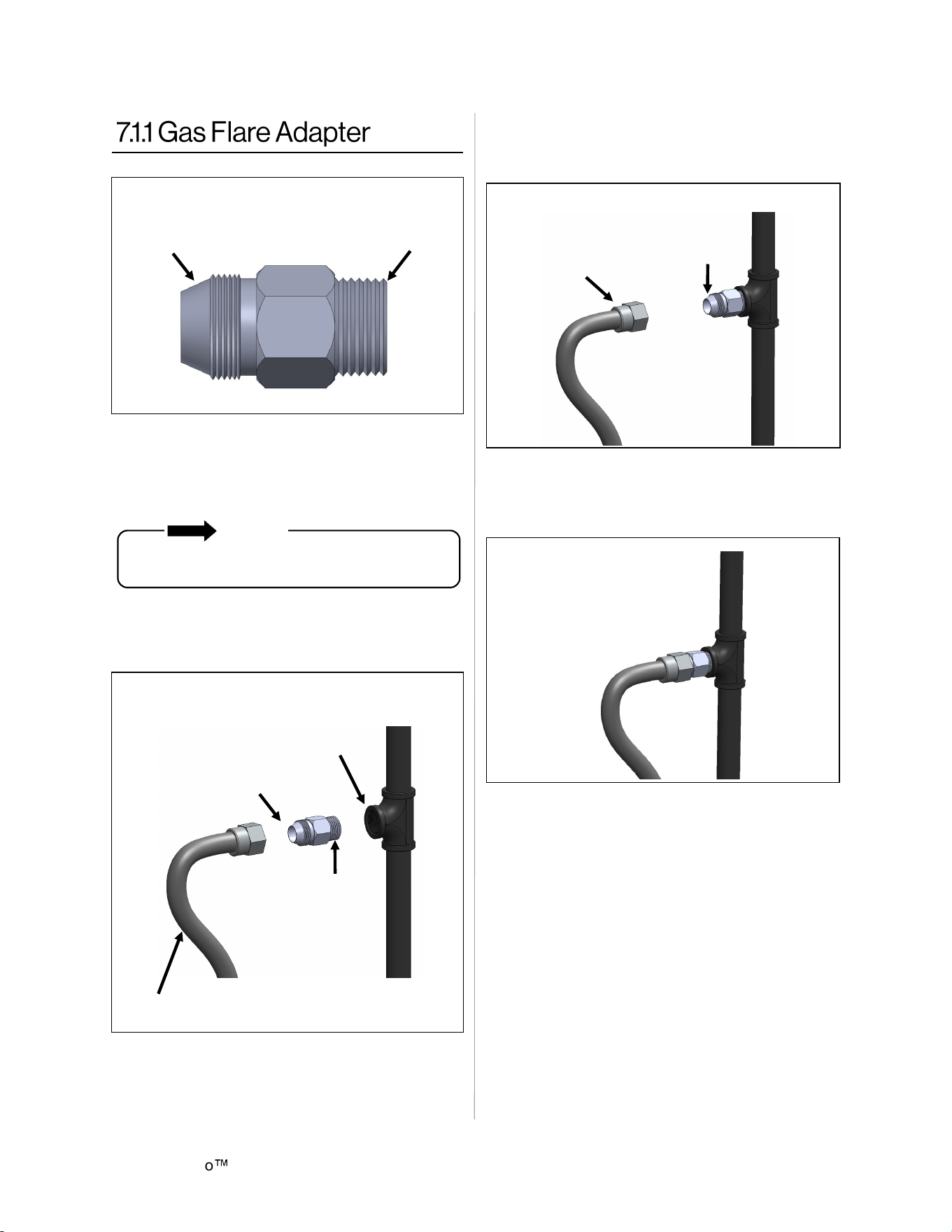
Demand Duo
H-Series with SENSEI CX Installation Instructions 44
1. Remove Gas Flare Adapter from the end of
the Gas Flex Hose Assembly.
2. Apply a pipe sealant approved for gas to the
3/4 NPT side of the Gas Flare Adapter.
3. Thread the 3/4 NPT side of the Gas Flare
Adapter into the field connection gas
supply (Figure 49).
NOTE
DO NOT apply sealant to the parallel threads
on the flare side of the Gas Flare Adapter.
4. Thread the flare side of the 36 in. Gas Flex
into the flare side of the Gas Flare
Adapter (Figure 50).
6. Leak test ALL gas fittings and assembly
using a leak test solution, soap and water,
or an equivalent nonflammable solution.
7. If leak is identified at the flex connection,
gradually tighten fitting until leak stops.
DO NOT connect gas flex directly to pipe
threads of gas supply pipe or appliance. Install
Gas Flex using only the Gas Flare Adapter
provided.
5. Use a backer wrench to tighten all
connections to the recommended torque
value of 62 lbs-ft.
36 in. Gas Flex
3/4 NPT
Field
Connection
Flare Side
3/4 NPT Side
Figure 49
Flare Side
36 in. Gas Flex
Figure 50
Figure 51
Flare Side
3/4 NPT
Side
Figure 48
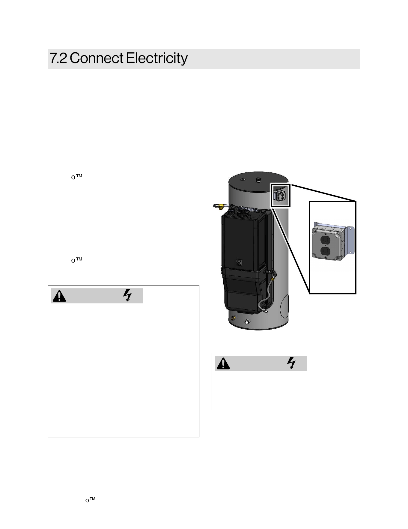
Demand Duo H-Series with SENSEI CX Installation Instructions 45
1. An electrical assembly is pre-installed on
the storage tank for single point electrical
connection (Refer to the Specifications
sections in this manual for electrical
requirements.
Connect power to the electrical assembly
by following the steps on the following
page.
• Do not use an extension cord or adapter
plug with this appliance.
• The water heater must be electrically
grounded in accordance with local codes
and ordinances or, in the absence of
local codes, in accordance with the
National Electrical Code, ANSI/NFPA No.
70.
• Indoor water heaters are equipped with a
three-prong (grounding) plug for your
protection against shock hazard and
should be plugged directly into a properly
grounded three-prong receptacle. Do not
cut or remove the grounding terminal
from this plug.
WARNING
When connecting the power supply, follow
these guidelines:
• Do not rely on the gas or water piping to
ground the water heater. Ground
locations are provided inside the water
heater.
• Do not exceed the limits of the 15A
circuit.
• The water heater requires 120 VAC,
60 Hz power from a properly grounded
circuit.
• Do not connect power to the Demand
Duo
H-Series system prior to
completing installation and filling the
system with water.
• The Tankless Water Heater wiring
diagram is located on the inside of the
water heater front cover. The controller
wiring diagram is located on the inside
front cover of the controller.
• When power is supplied, the water heater
maintains pump operation. If the Demand
Duo
H-Series system is not in use for
an extended period of time, disconnect
power from the system.
To connect the power supply:
Shut off building supply power prior to
connecting to the electrical assembly.
Failure to do so may result in property
damage, bodily harm, or death.
WARNING
Electrical
Assembly with 20
A, 125 V, 2-Pole,
3-Wire Grounding
Receptacle
Figure 52
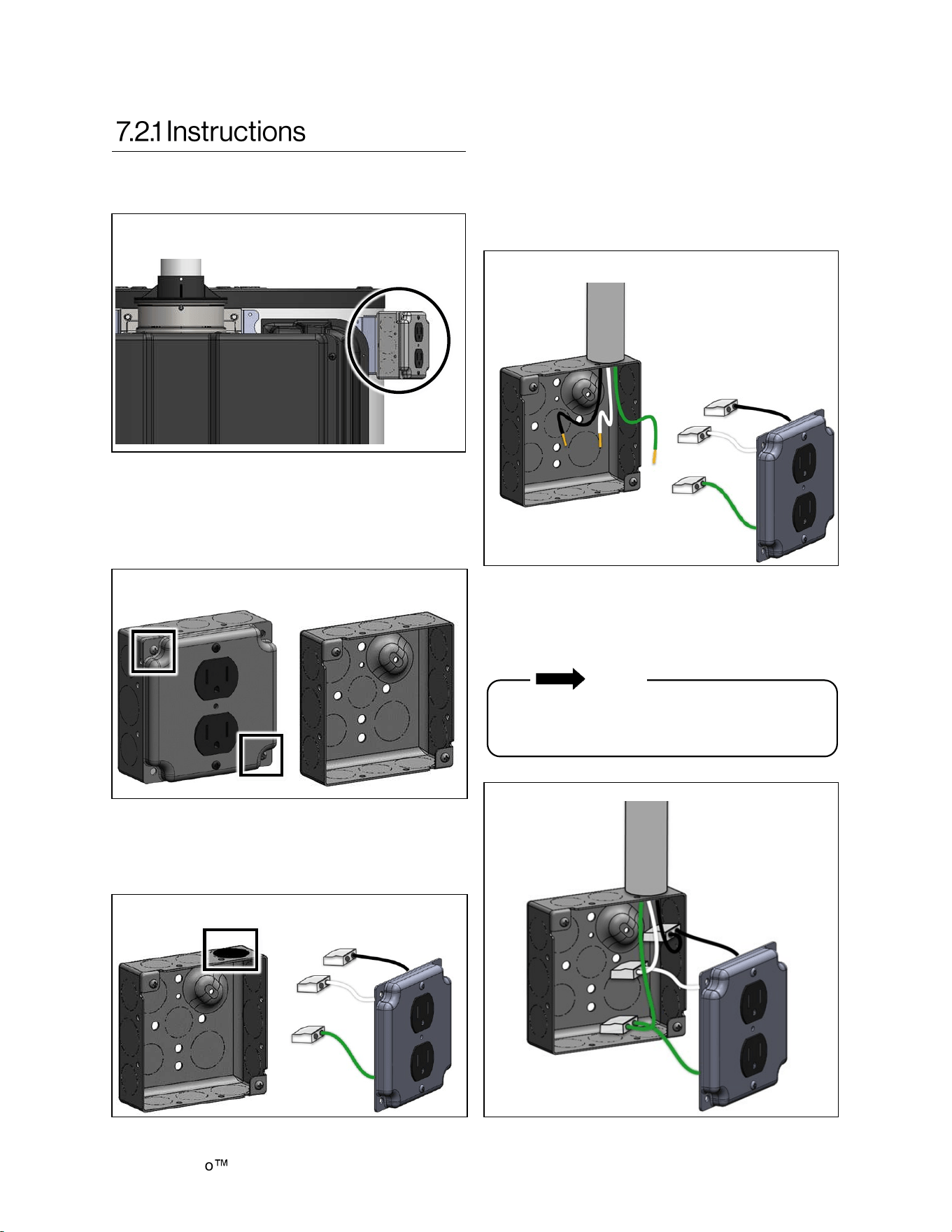
Demand Duo
H-Series with SENSEI CX Installation Instructions 46
3. Remove the desired knockout along the
perimeter of the electric box for conduit
installation (Figure 55).
2. Remove the two screws around the outlet
cover. Remove the outlet cover and prewired
outlet (Figure 54).
4. Install conduit into the knockout opening and
pull the green, white and black wires into the
box.
5. Strip the green, white, and black field
supplied wires 1/2 in. Make sure the
conductors are completely bare (Figure 56).
6. Match the wire colors, then grip the wire
firmly and push the conductor into open port
of the push in connector (Figure 57).
1. Locate the electric conduit on the side of
the water heater (Figure 53).
Use only one conductor per port. Verify
conductor is fully inserted to the back of the
connector.
NOTE
Figure 53
Figure 54
Figure 55
Figure 56
Figure 57
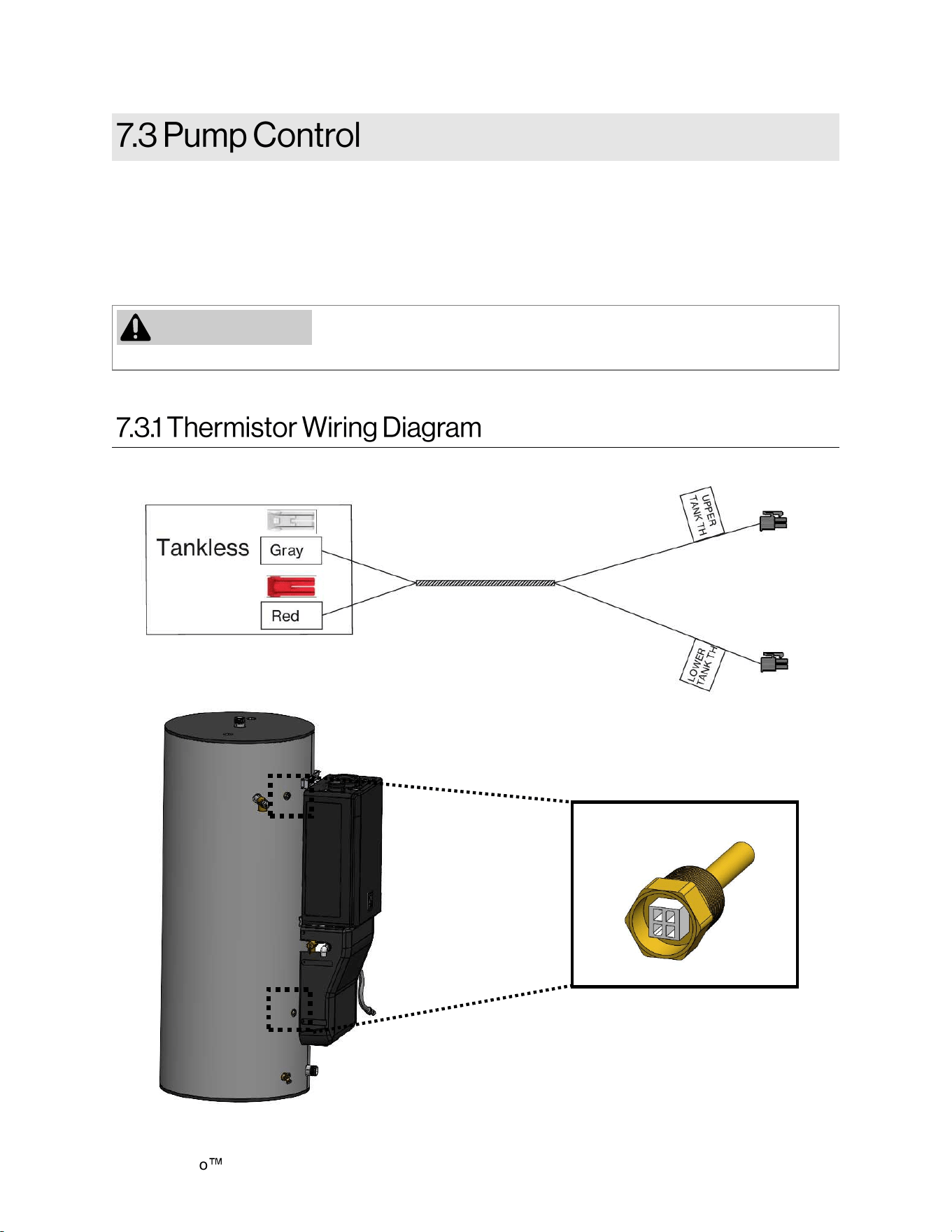
Demand Duo H-Series with SENSEI CX Installation Instructions 47
The PCB maintains communication between the tank and tankless via the tank thermistors to effectively
control the tank temperature based on the selected temperature on the tankless unit.
The system controller will energize (120V) the pump when the tank temperature drops. When the tank
temperature returns to the selected set temperature, the tankless will de-energize the pump and remain
in standby until the tank temperature drops again.
When power is supplied, the water heater will maintain pump operation.
If system is not in use for an extended period of time, disconnect power
from the system.
ATTENTION
Figure 58
Demand Duo
H-Series with SENSEI CX Installation Instructions 48
□ The water heater is not subject to corrosive
compounds in the air.
□ The water supply does not contain
chemicals or exceed total hardness that will
damage the heat exchanger.
□ Clearances from the water heater unit are
met.
□ Clearances from the vent termination / air
intake are met.
□ Ensure you have used the correct venting
products for the model installed and that you
have completely followed the venting
manufacturer’s installation instructions and
these installation instructions.
□ Verify that the vent system does not exceed
the maximum length for the number of
elbows used.
□ Purge the water line of all debris and air by
closing the hot isolation valve and opening
the cold isolation valve and its drain. Debris
will damage the water heater. Use a
bucket or hose if necessary.
□ Ensure that hot and cold water lines are not
crossed to the unit and are leak free.
□ A manual gas control valve has been placed
in the gas line to the water heater.
□ Ensure that a pressure relief valve is
installed with a rating that exceeds the BTU
input of the water heater model. Refer to
the rating plate on the side of the water
heater for BTU input.
□ Clean the inlet water filter by closing the
cold and hot water inlet isolation (shut-off)
valves. Put a bucket under the filter at the
bottom of the water heater to catch any
water that is contained inside the unit.
Unscrew the water filter. Rinse the filter to
remove any debris. Install the filter and open
the isolation valves.
□ Check the gas lines and connections for
leaks.
□ Confirm that the gas inlet pressure is within
limits.
□ Confirm that the water heater is rated for the
gas type supplied.
□ Confirm that the electricity is supplied from a
120 VAC, 60 Hz power source, is in a
properly grounded circuit, and turned on.
□ Verify the Thermistor wires are connected
properly from the PCB to the thermistors.
□ Confirm parameter settings are set
appropriately for the altitude.
□ Verify the system is functioning correctly by
connecting your manometer to the gas
pressure test port on the water heater.
Operate all gas appliances in the home or
facility at high fire. The inlet gas pressure at
the water heater must not drop below that
listed on the rating plate.
□ DO NOT introduce toxic chemicals such as
those used for boiler water treatment to the
potable water used for space heating.
□ If the water heater is not needed for
immediate use, then drain the water from the
heat exchanger.
□ Install the front panel.
□ Explain to the customer the importance of not
blocking the vent termination or air intake.
□ Explain to the customer the operation of the
water heater, safety guidelines, maintenance,
and warranty.
□ The installation must conform with local
codes or, in the absence of local codes, with
the National Fuel Gas Code, ANSI Z223.1/
NFPA 54, or the Natural Gas and Propane
Installation Code, CSA B149.1.
□ Leave this manual and the Rinnai
Tankless Water Heater manual taped to
the water heater, or give both manuals
directly to the consumer.
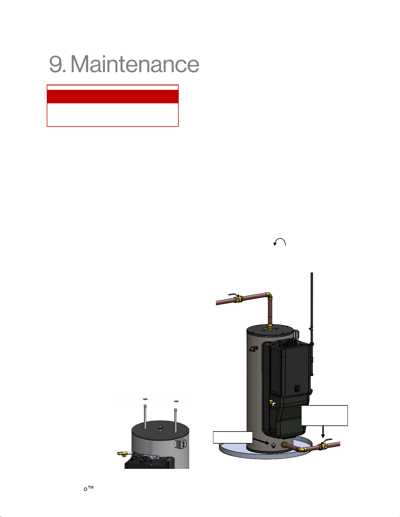
Demand Duo H-Series with SENSEI CX Installation Instructions 49
Anodes
The storage tank is equipped with two
magnesium anodes designed to extend the life of
the storage tank. Slowly consumed over time, the
anode protects the glass-lined tank from
corrosion. It is strongly recommended to inspect
the anodes every two (2) years. If more than half
of the anodes has been consumed, they should
be replaced. Instructions on how to change the
anodes can be obtained from the manufacturer.
The longevity of the storage tank can be reduced
when a water softener is introduced to fight hard
water. Sodium salts added by a softener can
make the water extremely conductive; therefore,
the anodes are consumed at a faster rate. In such
conditions, the anodes should be inspected on a
yearly basis.
In certain conditions, the anodes may react with
the water, producing discolored or smelly water.
The most common complaint is hot water that
smells like rotten eggs. This is the result of the
reaction between the anode and hydrogen
sulphide gas dissolved in the water, which is
common in well systems. This issue can usually
be eliminated or reduced by changing the
magnesium anodes to aluminum anodes and by
chlorinating the storage tank and plumbing
system. If the problem continues, special filtration
equipment may be required. Under no
circumstances are the anodes to be removed
from the water heater on a permanent basis.
Removal of the anodes will lead to premature
failure of the water heater and will void the
warranty.
Storage Tank
Drain a pail of water through the drain valve at
least once a year. This will remove excess
sediment from the bottom of the tank. This
sediment, if allowed to accumulate, will reduce
the efficiency and the life of the tank.
Draining the Storage Tank
To completely drain the storage tank:
1. Turn the power “OFF” to the system by
unplugging power to the system. (The system
will not be fully shut down by simply pressing
the power button on the controller)
2. Close the cold water supply manual shut-off
valve.
3. Connect one end of a garden hose to the
storage tank drain valve and put the other
end next to a free-flowing drain.
4. Open the drain valve by turning the knob
counter clockwise
5. Open a hot water faucet to allow air into the
system.
Topics in this section
• Replacement Parts
• Service/Maintenance Log
Anode Replacement
Procedure
1. Remove plastic
caps.
2. With 1-1/8 in.
socket wrench,
remove the anode.
Cold Water
Supply Valve
Drain Valve
Figure 60
Figure 59
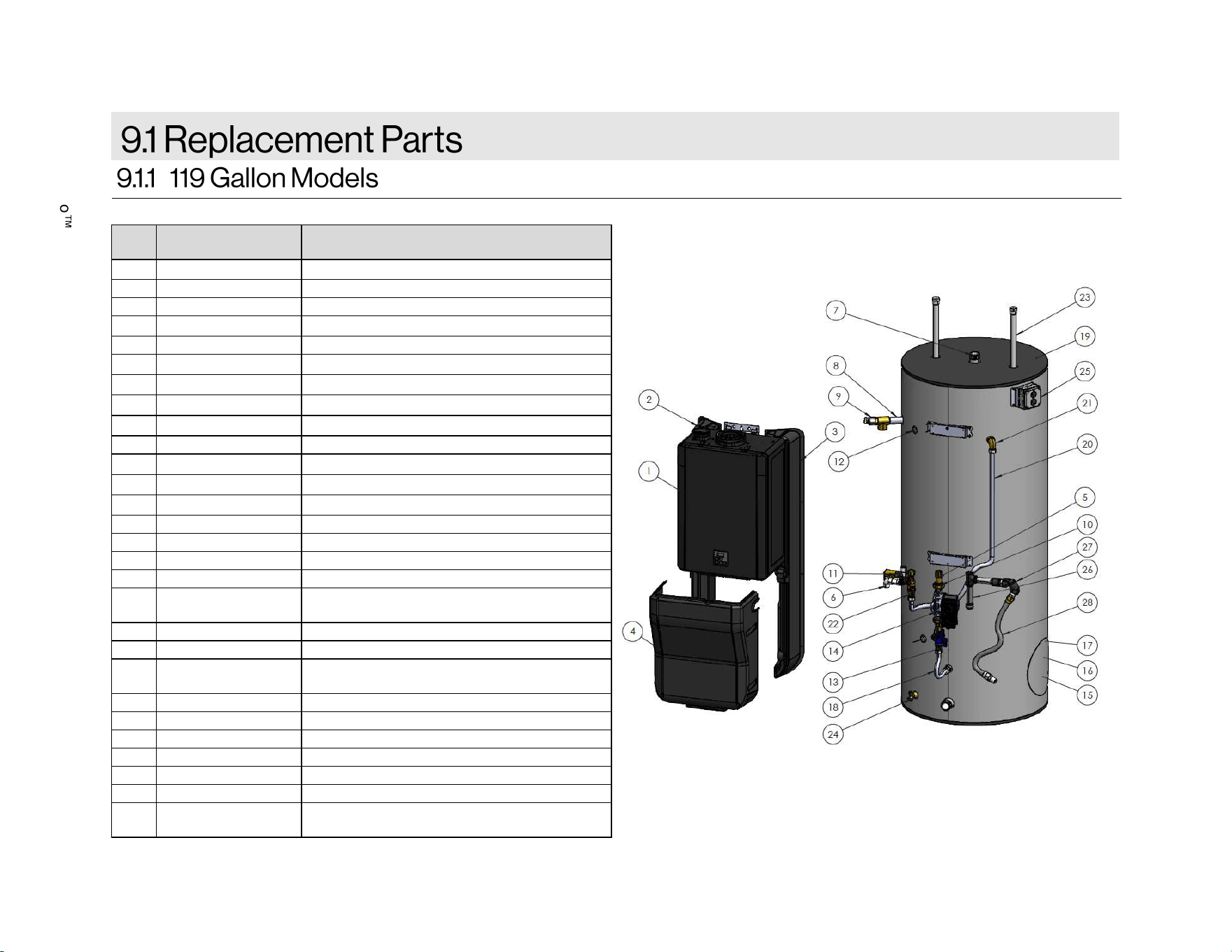
Demand Duo
H-Series with SENSEI CX Installation Instructions 50
ITEM
NO.
PART
NUMBER
DESCRIPTION
1 CX199iN/CX160iN RINNAI SENSEI CX TANKLESS
2 109001429 LEFT COVER
3 109001428 RIGHT COVER
4 109001430 FRONT COVER
5 104000297 PUMP UNION KIT
6 107000387 CONDENSATE PIPE (PVC)
7 107000308 1-1/2 IN DIELECTRIC NIPPLE
8 107000665 1 IN DIELECTRIC NIPPLE
9 107000472 FVMX-6LS 1 IN MALE T&P 500KBTU/HR
10 107000257 CHECK VALVE
11 107000673 PRV PIPE (45 DEG)
12 105002012 THERMISTOR, 3/4MNPT, 10K OHM
13 107000260 NIPPLE, 3/4 NPT
14 107000458 PUMP
15 107000311 TANK CLEANOUT FLANGE GASKET
16 107000312 HAND HOLE CLEANOUT COVER
17 109000633 CLEANOUT BOLTS 5/16IN-18 X 1 IN
18 107000255
FLEX, LENGTH 12 IN, 3/4 NPSH X 3/4
NPSH
19 107000636 TANK, 119 GALLON W/BRACKETS
20 107000666 TUBE, 47.95 X 3/4 NPSH X 3/4 NPSH
21 107000447
3/4IN BRASS FEMALE X MALE THREAD
90 DEG
22 103000122 HOT, COLD, PRV VALVE KIT
23 107000314 ANODE ROD, MAGNESIUM
24 107000315 BRASS DRAIN VALVE 3/4 X 2-3/4
25 105000337 ELECTRICAL ASSEMBLY
26 106000165 DIRT LEG 3/4 IN
27 106000164 GAS SWIVEL
28 106000181
GAS FLEX HOSE AND SWIVEL ASSY
0.75 IN
Figure 61
Table 20
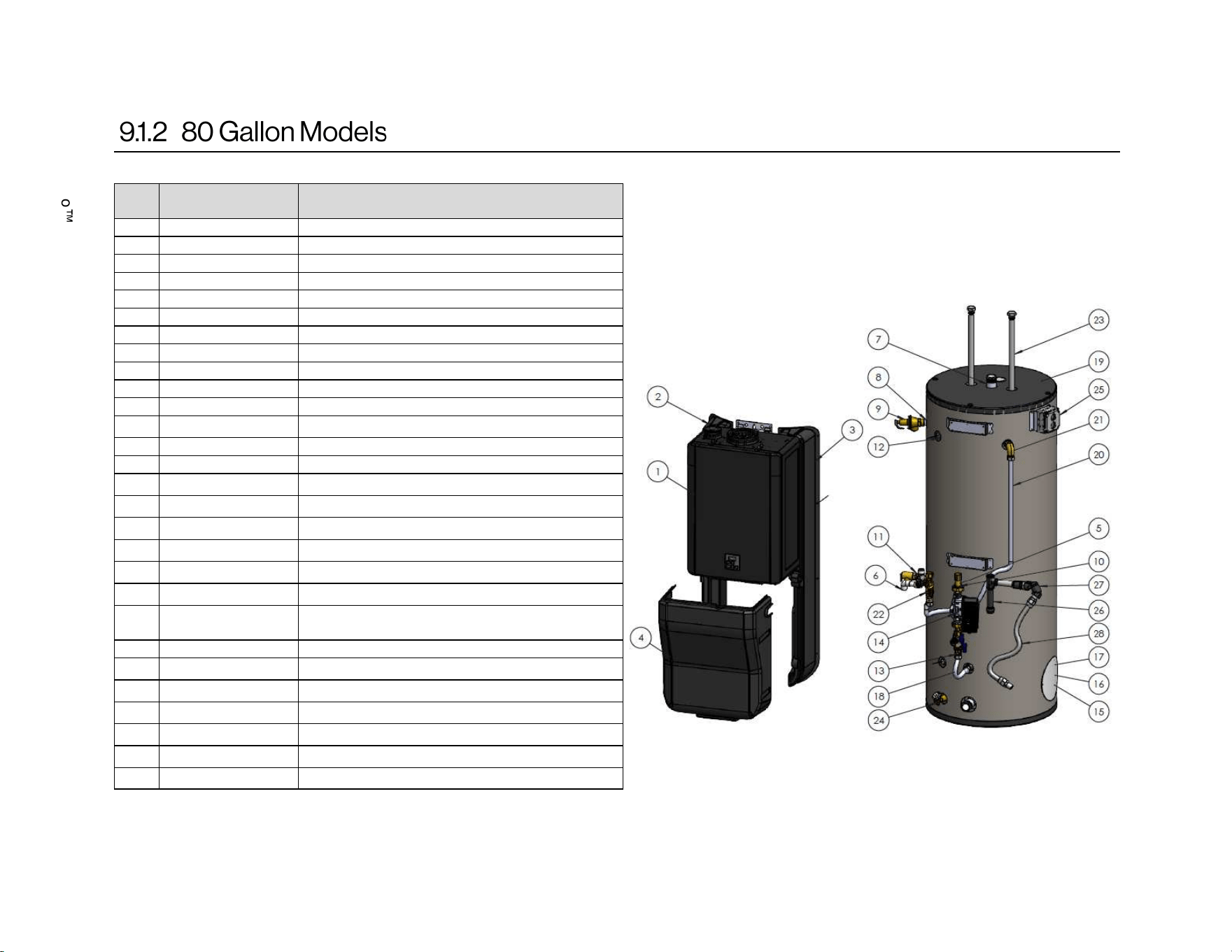
Demand Duo H-Series with SENSEI CX Installation Instructions 51
ITEM
NO.
PART
NUMBER
DESCRIPTION
1 CX199iN/CX160iN RINNAI SENSEI CX TANKLESS
2 109001429 LEFT COVER
3 109001428 RIGHT COVER
4 109001430 FRONT COVER
5 104000297 PUMP UNION KIT
6 107000387 CONDENSATE PIPE (PVC)
7 107000308 1-1/2 IN DIELECTRIC NIPPLE
8 107000665 1 IN DIELECTRIC NIPPLE
9 107000472 FVMX-6LS 1 IN MALE T&P 500KBTU/HR
10 107000257 CHECK VALVE
11 107000673 PRV PIPE (45 DEG)
12 105002012 THERMISTOR, 3/4MNPT, 10K OHM
13 107000260 NIPPLE, 3/4 NPT
14 107000458 PUMP
15 107000311 TANK CLEANOUT FLANGE GASKET
16 107000312 HAND HOLE CLEANOUT COVER
17 109000633 CLEANOUT BOLTS 5/16IN-18 X 1 IN
18 107000255 FLEX, LENGTH 12 IN, 3/4 NPSH X 3/4 NPSH
19 107000635 TANK, 80 GALLON W/BRACKETS
20 107000398 TUBE, 43.95 X 3/4 NPSH X 3/4 NPSH
21 107000447
3/4IN BRASS FEMALE X MALE THREAD 90
DEG
22 103000122 HOT, COLD, PRV VALVE KIT
23 107000314 ANODE ROD, MAGNESIUM
24 107000315 BRASS DRAIN VALVE 3/4 X 2-3/4
25 105000337 ELECTRICAL ASSEMBLY
26 106000165 DIRT LEG 3/4 IN
27 106000164 GAS SWIVEL
28 106000181 GAS FLEX HOSE AND SWIVEL ASSY 0.75IN
Table 21
Figure 62
Demand Duo
H-Series with SENSEI CX Installation Instructions 52
Date Service / Maintenance Completed
Demand Duo H-Series with SENSEI CX Installation Instructions 53
Limited Warranty for Demand Duo H-Series
What Is Covered?
The Rinnai Standard Limited Warranty covers any defects in materials or workmanship when the
product is installed and operated according to Rinnai written installation instructions, subject to the terms
within this Limited Warranty document. This Limited
Warranty applies only to products that are installed
correctly in the United States and Canada. Improper installation may void this Limited Warranty. In order
for this warranty to apply, it is required that you use a trained and qualified professional who has
attended a Rinnai installation training class before installing this water heater. This Limited Warranty
coverage as set out in the table below extends to the original purchaser and subsequent owners, but
only while the product remains at the site of the original installation. This Limited Warranty only extends
to the first / original installation of the product and terminates if the product is moved or reinstalled at a
new location.
*The heat exchanger warranty will be 8 years or 12,000 operation hours, whichever occurs first.
Notes:
• From date of purchase, period of coverage is reduced to 8 years or 12,000 operation hours,
whichever occurs first, if the Rinnai water heater temperature settings exceeds 160°F (71°C).
• The integrated controller has a 1 year warranty on parts.
What Will Rinnai Do?
Rinnai will repair or replace the covered product or any part or component that is defective in materials
or workmanship as set forth in the above table. Rinnai will pay reasonable labor charges associated with
the repair or replacement of any such part or component during the term of the labor warranty period. All
repair parts must be genuine Rinnai parts. All repairs or replacements must be performed by a licensed
professional who is properly trained to do the type of repair.
Replacement of the product may be authorized by Rinnai only at its sole discretion. Rinnai does not
authorize any person or company to assume for it any obligation or liability in connection with the
replacement of the product. If Rinnai determines that repair of a product is not possible, Rinnai may
replace the product with a comparable product at Rinnai’s sole discretion. The warranty claim for
product parts and labor may be denied if a component or product returned to Rinnai is found to be free
of defects in material or workmanship; damaged by improper installation, use or operation; or damaged
during return shipping.
How Do I Get Service?
You must contact a trained and qualified professional for the repair of a product under this Limited
Warranty. For the name of a trained and qualified professional, please contact your place of purchase,
visit the Rinnai website (www.rinnai.us), call Rinnai at 1-800-621-9419 or write to Rinnai at 103
International Drive, Peachtree City, Georgia 30269.
Proof of purchase is required to obtain warranty service. You may show proof of purchase with a dated
sales receipt, or by registering within 30 days of purchasing the product. To register your Rinnai
Tankless Water Heater, please visit www.rinnai.us. For those without internet access, please call
1-866-RINNAI1 (746-6241). Receipt of Registration by Rinnai will constitute proof-of-purchase for this
product. Registration of product installed in new home construction may be verified with a copy of the
closing papers provided by the initial home buyer. However, Registration is not necessary in order to
validate this Limited
Warranty.
Item Warranty Coverage
Heat Exchanger* 8 Years
Storage Tank 6 Years
All Other Parts and Components 5 Years
Reasonable Labor 1 Year
Table 22

Demand Duo
H-Series with SENSEI CX Installation Instructions 54
What Is Not Covered?
This Limited
Warranty does not cover any failures or operating difficulties due to the following:
There is no warranty coverage on product installed in a closed loop application, commonly associated
with space heating only applications.
This Limited
Warranty does not apply to any product whose serial number or manufacture date has
been defaced.
This Limited
Warranty does not cover any product used in an application that uses chemically treated
water such as a pool or spa heater.
Limitation on Warranties
No one is authorized to make any other warranties on behalf of Rinnai America Corporation. Except as
expressly provided herein, there are no other warranties, expressed or implied, including, but not limited
to warranties of merchantability or fitness for a particular purpose, which extend beyond the description
of the warranty herein.
Any implied warranties of merchantability and fitness arising under state law are limited in duration to the
period of coverage provided by this Limited Warranty, unless the period provided by state law is less.
Some states do not allow limitations on how long an implied Limited
Warranty lasts, so the above
limitation may not apply to you.
Rinnai shall not be liable for indirect, incidental, special, consequential or other similar damages that
may arise, including lost profits, damage to person or property, loss of use, inconvenience, or liability
arising from improper installation, service or use. Some states do not allow the exclusion or limitation of
incidental or consequential damages, so the above limitation may not apply to you.
This Limited Warranty gives you specific legal rights, and you may also have other rights which vary
from state to state.
www.rinnai.us/warranty
• Accident, abuse, or misuse
• Alteration of the product or any component part
• Misapplication of this product
• Improper installation (such as but not limited to)
− Product being installed in a corrosive
environment
− Condensate damage
− Improper venting
− Incorrect gas type
− Incorrect gas or water pressure
− Absence of a drain pan under the appliance
• Improper maintenance (such as but not limited
to scale build-up, freeze damage, or vent
blockage)
• Incorrect sizing
• Any other cause not due to defects in materials
or workmanship
• Problems or damage due to fires, flooding,
electrical surges, freezing or any acts of God
• Any damage caused by poor water quality
• Operating the water heater with anything other
than potable water at all times
• Force majeure

Demand Duo H-Series with SENSEI CX Installation Instructions 55

Demand Duo
H-Series with SENSEI CX Installation Instructions 56