
1 | Page
* Installer: Leave this manual with the proud new owner *
Also be sure to check the grill box completely for ALL parts
including the rotisserie spit rod (if applicable)
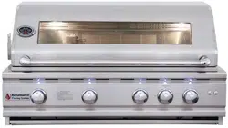
Renaissance Cooking Systems
Owner’s Manual
For Outdoor Use Only
RJC26A, RJC32A, RJC32AL, RJC40A,
RJC40AL, RON30A, RON38A & RON42A
These grills are tested and certified to the ANSI-Z21.58/CSA 1.6.standards.
This owner’s manual was updated November 2021
For the latest news, recipes and cooking tips for your new
Renaissance Cooking Systems grill, check out www.RCSGasGrills.com
Installation, Operation, Maintenance
Instructions & Parts List
Models:
America's Best Value in Outdoor Kitchen Equipment
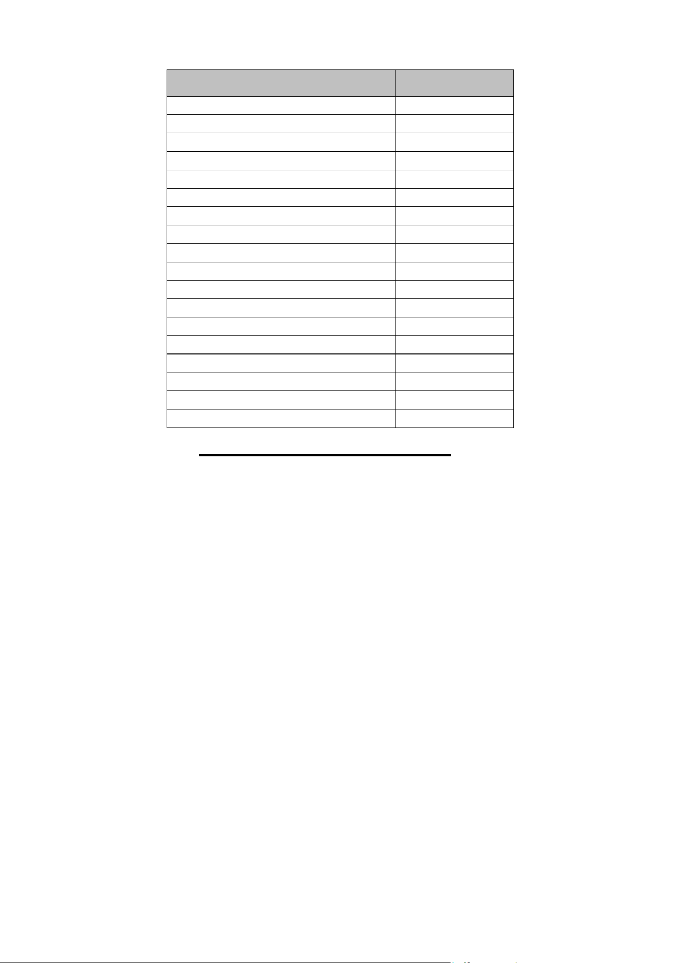
Contents Page
For Your Safety
3-7
Safety Rules
8
Clearance to Combustibles
9
BTU Ratings
10-11
Gas Barbecue Specifications
11
LP Tank Requirement
11-12
Installation Location/Cut Outs
13
Gas Connections
13-15
Electrical/Wire Diagram
16-17
Burner Adjustments
18-19
Lighting Instructions
20-21
Operation
21
First Time Operation
22
Cleaning and Maintenance
23
Gas Conversion /Trouble Shooting
24-26
Troubleshooting
26
Parts Diagram
27-32
Warranty
33
Message to the Proud Owner
Congratulations on the purchase of this high quality, high
performance grill.
Read this manual carefully to understand all the instructions
about how to install, operate and maintain for optimum
performance and longevity.
Keep this manual in a safe place for future reference.
For any assistance, contact us. Make sure to provide the Model
Number and Serial Number of the grill which is located on the
right or left hand side of the control panel depending on model:
Premier Series: RJC26A, RJC32A, RJC32AL, RJC40A & RJC40AL – left side
Cutlass Pro Series: RON30a, RON38a & RON42a – right side
Thank you for purchasing your new RCS grill. We wish
you many years of grilling pleasure.
2 | P ag e
3 | Page
Safety and Installation Instructions
GRILL INSTALLATION
This gas grill must be installed in accordance with all local codes.
If installation is planned in an area with no local codes, the gas grill must be
installed in accordance with the National Fuel Gas Code ANSI Z223.1 and
storage and handling of liquefied petroleum gases, ANSI/NFPA 58 or CSA
B149.1 natural gas and propane installation code.
WARNING: Improper installation, adjustment, alteration, service or
maintenance can cause injury or property damage, and void the warranty.
Read the installation, operating and maintenance instructions thoroughly
before installing or servicing this equipment.
NOTE: This appliance is not intended for commercial use.
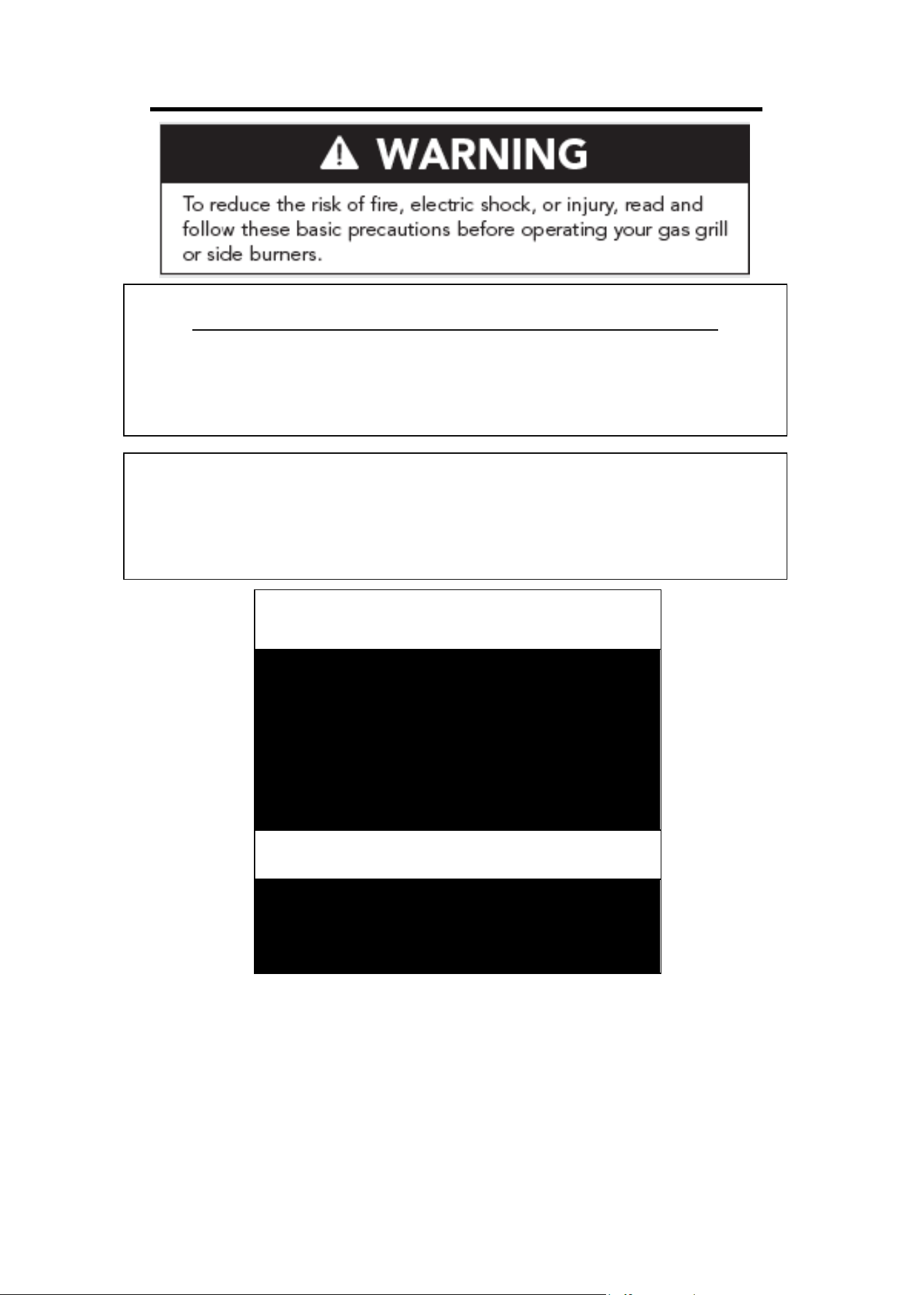
FOR YOUR SAFETY
1. If you smell gas:
2. Shut off gas to the appliance.
3. Extinguish any open flames.
4. Open lid.
5. If odor continues, immediately
call your gas supplier.
!!! WARNING !!!
Read the “Lighting Instructions” in
this manual, before lighting this
appliance.
NOTE: The manufacturer cannot be held responsible for damage or injury
cause by improper use of this appliance.
NOTE: Do not leave the unit under the sun with the protective film (where
applicable) on for a long period of time as it will make the film difficult to
remove and/or leave markings on the materials which are not covered by
warranty.

4 | Page
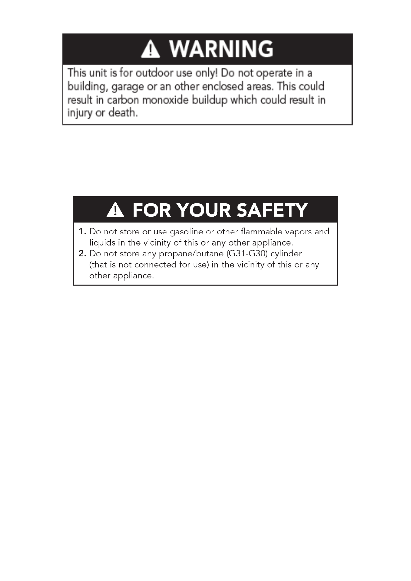
FOR YOUR SAFETY
1. Do Not store or use gasoline,
caustic or other flammable vapors
and liquids in the vicinity of this
or any other appliance.
2. An LP cylinder not connected for
use shall not be stored in the vicinity
of this or any other appliance..
TESTED IN ACCORDANCE WITH ANSI
STANDARD FOR OUTDOOR COOKING
GAS APPLIANCES. THIS GRILL IS FOR
OUTDOOR USE ONLY.
Check your local building codes for the proper
method of installation. In the absence of local
codes, this unit should be installed in
accordance with the National Fuel Gas Code
No. Z223.1-CAN/CGA—B149.1, natural gas
installation code or CAN/CGA—B149.2,
propane installation code.
CALIFORNIA PROPOSITION 65-
!!! WARNING !!!
The Burning of gas cooking fuel generates
Some by-products which are on the list of
substances which are known by the State of
California to cause cancer or reproductive
harm. California law requires businesses to
warn customers of potential exposure to
such substances. To minimize exposure to
these substances, always operate this unit
according to the use and care manual,
ensuring you provide good ventilation when
cooking with gas.
The Burning of gas cooking fuel generates
substances which are known by the State of
STATE OF MASSACHUSETTS !!!
WARNING !!!
The Burning of gas cooking fuel generates
substances which are known by the State of
The Burning of gas cooking fuel generates
Massachusetts requires all gas be installed
using a plumber or gas fitter carrying the
appropriate Massachusetts license.
All permanetly-installed natural gas or
propane installations require a "T" handle
type manual gas valve be installed in the
gas supple line to this appliance.
This does not apply to portable propane
installations using a 20 pound cylinder.
Safety and Installation Instructions
Do not use the grill as storage area for flammable or
caustic materials. Keep area clear and free from
combustible, gasoline, swimming pool chemicals, and
other flammable vapors and liquids. Failure to do so
can result in death, explosion, or fire.
Location of your Barbecue
Most importantly, this is an outdoor appliance. Ensure your barbecue is positioned safely away
from anything that can catch fire.
Under no circumstances is this barbecue to be used indoors. This includes garages or any
other enclosed area.
Clearance from Combustibles: Ensure your barbecue remains at a distance of at least 24” from any
combustible material such as wood, gyprock, paper and plants. Do not store combustible, caustic
materials, gasoline or flammable liquids or vapors within 48” of the barbecue. Do not locate
under unprotected combustible materials unless a properly-sized vent hood is included. Do not
store ANY types of chemicals, gasoline, flammable liquids or vapor near the grill or any
stainless components, cabinets, doors, drawers, etc.
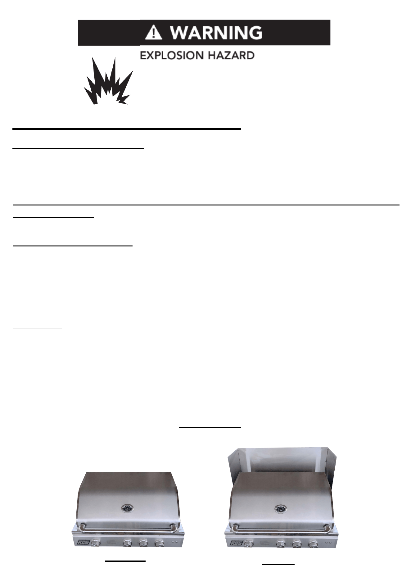
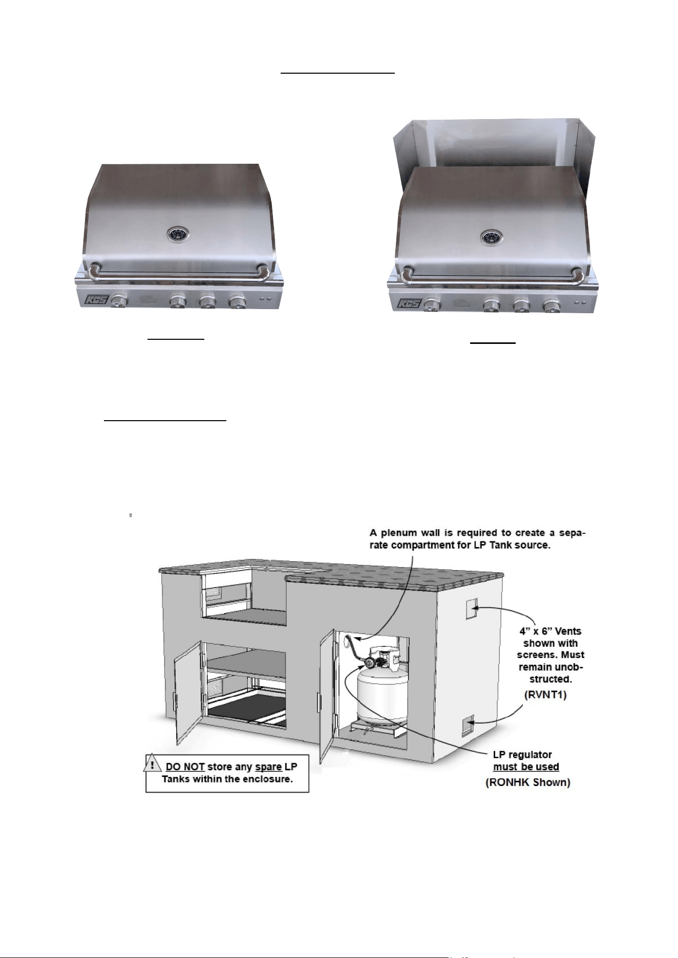
Wind Guard: WARNING! Your RCS grill should NOT be installed with the back of the grill facing
frequent, prevailing winds like a large body of water or open space unless there is a substantial back
splash or some way of blocking the wind. In some rare occurrences, when there is a strong wind
present, it can cause heat that is normally exhausted through the rear ports to be forced back into the
grill and may cause overheating of the control panel and controls. Damage caused by this type of
installation is not covered by warranty. If you are experiencing this problem, please contact us to order
a wind guard which may or may not solve your problem but may be a possible alternative to changing
the location of the grill if it has been installed with the rear of the grill facing the prevailing wind.
Model/Part Number
RWGM - RJC26A/RJC32A/ RJC32AL/RON30A
RWGL - RJC40A/RJC40AL/RON38A/RON42A
BEFORE
AFTER
5
| P ag e
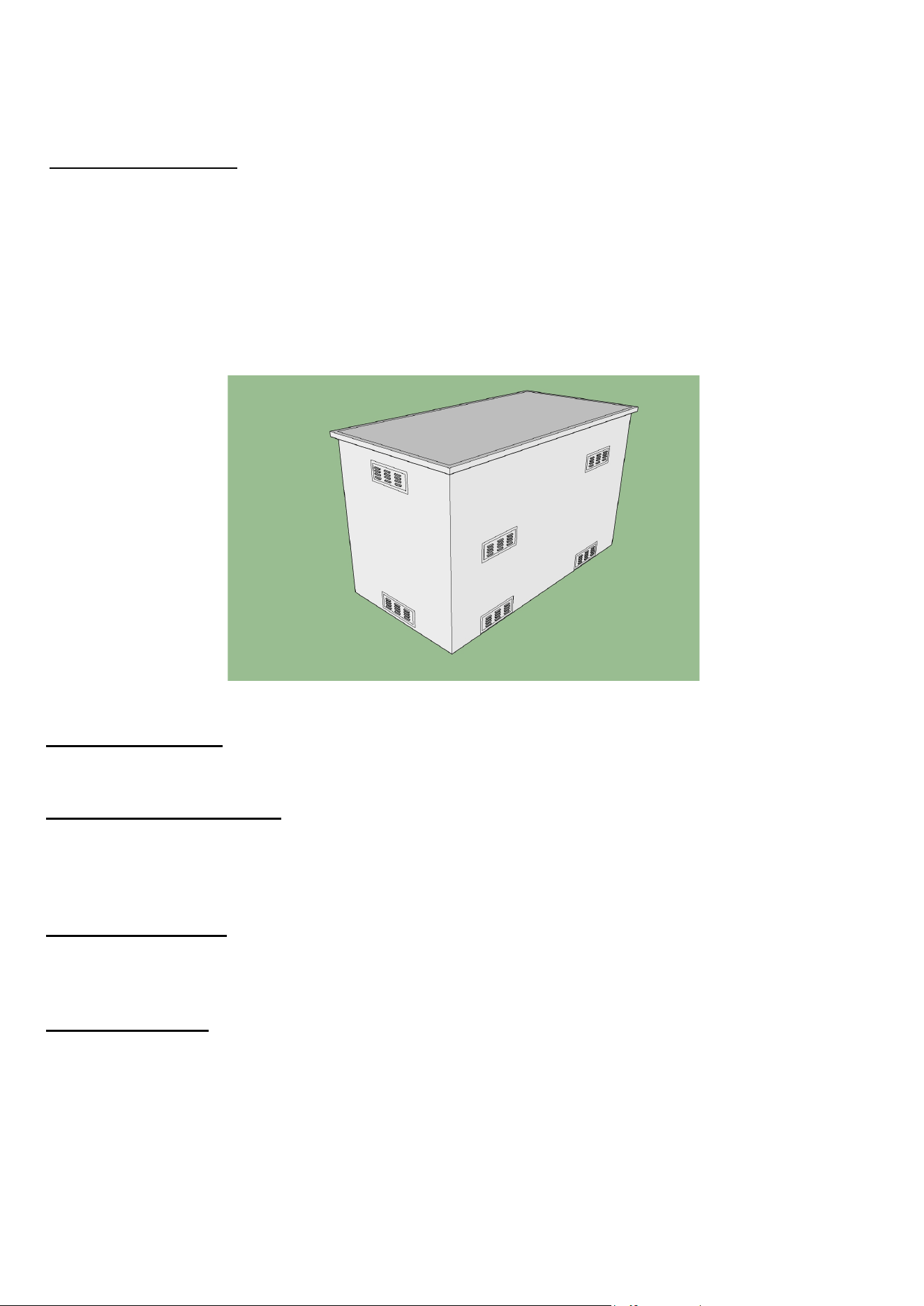
Adequate Ventilation: Ensure there is adequate ventilation for both the barbecue, cylinder
and all appliances located in this cabinet. Adequate ventilation is required for proper
combustion and to prevent gas build up. Kitchen vents (RVNT1) are required every 4 feet to
help ventilate and prevent dangerous gas build up, remove excess heat, add air to help with
air/fuel mix for the grills and allows moisture/ condensation to evaporate. When using an
exhaust hood, the area above the cooking surface of the grill must be covered with a hood larger
than the cooking area of the grill, AND with a minimum of 1200 CFM (cubic feet per minute) for
proper outdoor application.
Firm Level Surface: Use your barbecue only on a firm level surface. This barbecue is
not designed for recreational vehicles, and shall not be installed on a boat or any marine craft.
Protection from Weather: Keep the barbecue protected from adverse weather,
including rain and high winds. Grill and side burner covers are available that have been
specially designed for this range of barbecues. Allow clear access to the entire gas supply, hose
and regulator.
Maintenance Access: When your barbecue is installed, you should be able to access the gas
supply line including the gas piping or hose, gas regulator, gas cylinder and any shut off valves.
Do not grout or add silicon in barbecue grill.
Partial Enclosures: Many backyards have areas that are partially closed off, such as
balconies and pergolas. In some cases, it is hard to decide whether these partially
enclosed areas should be classified as indoor areas, particularly in terms of permanent (non-
closable) ventilation. The gas safety authorities have agreed on the definition of partial
enclosures below (See page 13).
6 | P ag e
7 | Page

Safety Rules
8 | P ag e
• It is important to follow these rules to avoid fire hazard, property damage or bodily injury from
improper installation or usage of the grill. For safety, READ all rules carefully and check local
codes.
• It is prohibited to install the grill in recreational vehicles/mobile homes, trailers, boats, etc. The
grill is for outdoor installation and use only.
• Ensure proper installation by following the installation instructions. Make sure to know where
the gas supply shut-off valve is located. It should always be readily and easily accessible.
• Check all gas line joints & connections for gas leak with soap water solution. Never check gas
leak with an open flame.
• Do not attempt to repair or replace any part of the grill unless specifically recommended in this
manual. All other services should be performed by a qualified service technician.
• Do not place clothing or other flammable material on or near the appliance. Do not wear loose-
fitting clothes or long sleeves while using the grill as some fabrics may be highly flammable.
• Children should be carefully supervised when they are in the vicinity of the grill. Do not allow
them to get close to the grill while in use. Items of interest to children should not be stored in or
around the grill in the cabinet or in the masonry enclosure. Portions of the grill can be extremely
hot while in use and can cause severe burns.
• Protect your hand with a glove or mitt when opening and operating the grill. Open grill lid slowly
to allow heat and smoke to escape before fully opening.
• Never use aluminum foil to line the crumb pan or grill racks. This can alter airflow for proper
combustion and also build up heat in the control area causing the knobs and igniters to melt
and void your grill warranty.
• Grease is highly flammable. Allow hot grease to cool down before attempting to handle it.
Clean grease tray often so that grease does not accumulate and stay in it which may cause a
fire.
• Do not operate the grill in a windy area. For windy areas we recommend the RCS Wind Guard.
(see page 13)
• Do not obstruct the flow of air into the front of the grill or any vent areas.
• The grill should be installed facing towards the prevailing winds to help eliminate drafts from
behind which can heat up and damage the control panel, controls, electronics, and voids
warranty. We have wind guards available to help protect against the wind. (see page 13)
• Always keep your grill CLEAN of grease to prevent dangerous grease fires.
• Have an ABC extinguisher accessible at all times. Never attempt to etinguish a grease
fire with water or other liuids.

First Time Operation
Y
our RCS
A
ppliance c
omes per-assem
bled and requires very little setup. We do however;
recommend the use of professional help during the installation of your unit as improper
installation may affect your warranty. Remove the unit from the box along with all accessories
and check that no damage has occurred to the unit or any parts. Remove all packaging
materials, labels and protective plastic film before you start cooking. Burners: Check the burner
tubes and remove any obstructions that may be in the ports or holes. Using cold water and a
brush will be sufficient. Make sure all foreign particles are removed from the burner before use.
Make sure the air shutter on the burners is slightly opened (to about 1/8" for NG and 1/4" for LP).
When finished ensure that the burners are aligned with the valve orifice and seated in the bracket
slot. This is accomplished by first placing the burner tube shutter hole securely over the valve
orifice and ensuring the male post on the grill chassis rests in the corresponding slot in the rear
of the burner. Failure to do so could result in a fire and injury.
MAIN BURNERS:
Before cooking with your grill the first time, burn off any foreign matter and rid the unit of any
odors by operating the unit for about 20 minutes with all lower burners on high.
The flame should have a bluish color to it. It may have a tint of yellow and adjustment
to the air shutters can be made to obtain a blue flame with a slight yellow tip.
Although the grill can be operated with the hood closed, do not continually operate
the rotisserie burner with the hood closed. This will damage the grill and void the
warranty. Be sure to remove the upper rack when operating this rotisserie burner.
The grill should be preheated with the main burners on HIGH for 15 minutes with the hood
closed. If you have an optional infrared burner, the grill lid must remain open while the infrared
burner is in use.
Temperature Settings
- Use HIGH burner setting for searing, heavy cooking, preheat and clean up.
- Use other burner settings to create temperatures to fit your personal cooking preferences.
- Internal temperatures may v
ary with outside temperature and wind conditions.
Rem
ember- y
our heat
indic
ator
is
just that, an INDICATOR not an actual thermometer.
ALSO-the temperature at the cooking surface
is significantly higher than what the heat
indicator shows in the lid. Your RCS
grill has been designed and manufactured to provide
optimum cooking temperatures across a wide range of foods, without “cooking itself to death!”
You can cook poultry and larger cuts of meat slowly if you turn OFF the burner directly under
the food and use adjacent burners to supply
heat (convection cooking or Indirect Cooking).
When cooking fattier foods, cooking with indirect heat also greatly reduces flare-ups.
Fats and juices that drip
down can cause flare-ups. Since some flare-ups do impart a distinctive
and desirable flavor, taste and color to
foods being grilled, they should be carefully and
reasonably encouraged. Uncontrolled or excessive flare-ups,
however, will ruin your food
. DO
NOT USE ALUMINUM FOIL FOR GREASE ISSUES.
9 | P ag e
Gas Connections
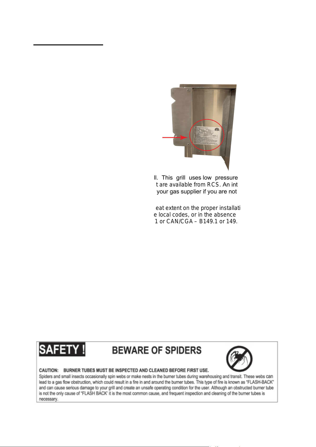
Check gas type – use only the type of gas indicated in the rating plate.
-The rating label is located on the left or right hand outside of the unit.
DO NOT connect high pressure to this grill. This grill uses low pressure 1/2" psi to
operate. You MUST use the regulator(s) that are available from RCS. An intermediate (step-
down) regulator may be necessary. Check with your gas supplier if you are not sure.
Safe and satisfactory operation depends to a great extent on the proper installation of the
appliance. The installation must comply with the local codes, or in the absence of local codes, with
either the National Fuel Gas Code, ANSI Z223.1 or CAN/CGA – B149.1 or 149.2.
Installer supplied manual gas shut-off valves must be installed in an easily accessible location in
the gas supply line ahead of the pressure regulator (4”W.C.).
The outdoor cooking gas appliance and its individual shut-off valve must be
disconnected from the gas supply piping system during any pressure testing of the system at
test pressures in excess of
1
/
2
Psi (3.5kPa). Over-pressure will cause the valves to fail and void the
warranty!
The supply line must be sized and installed to provide a sufficient supply of gas to meet the
maximum demand of the grill without undue loss of pressure. The sealant used on the threaded
joints of the gas pipe must be a type resistant to the action of LP gases.
RATING PLATE LOCATION
10 | P ag e
11 | P ag e
GAS BARBECUE SPECIFICATIONS
BURNER INPUT RATING
Natural Gas Connection:
Appliance pressure 4” W.C.
Inlet pressure 5” – 14” W.C.
Check with your local gas utility company or with local codes before installing gas lines.
Installation in Canada must be in accordance with the standard CAN/CGA- B149.2
A licensed contractor or local gas company representative must perform all gas
connections
L
P Gas Connection
Appliance pressure 10” W.C.
Inlet pressure 11” – 14” W.C.
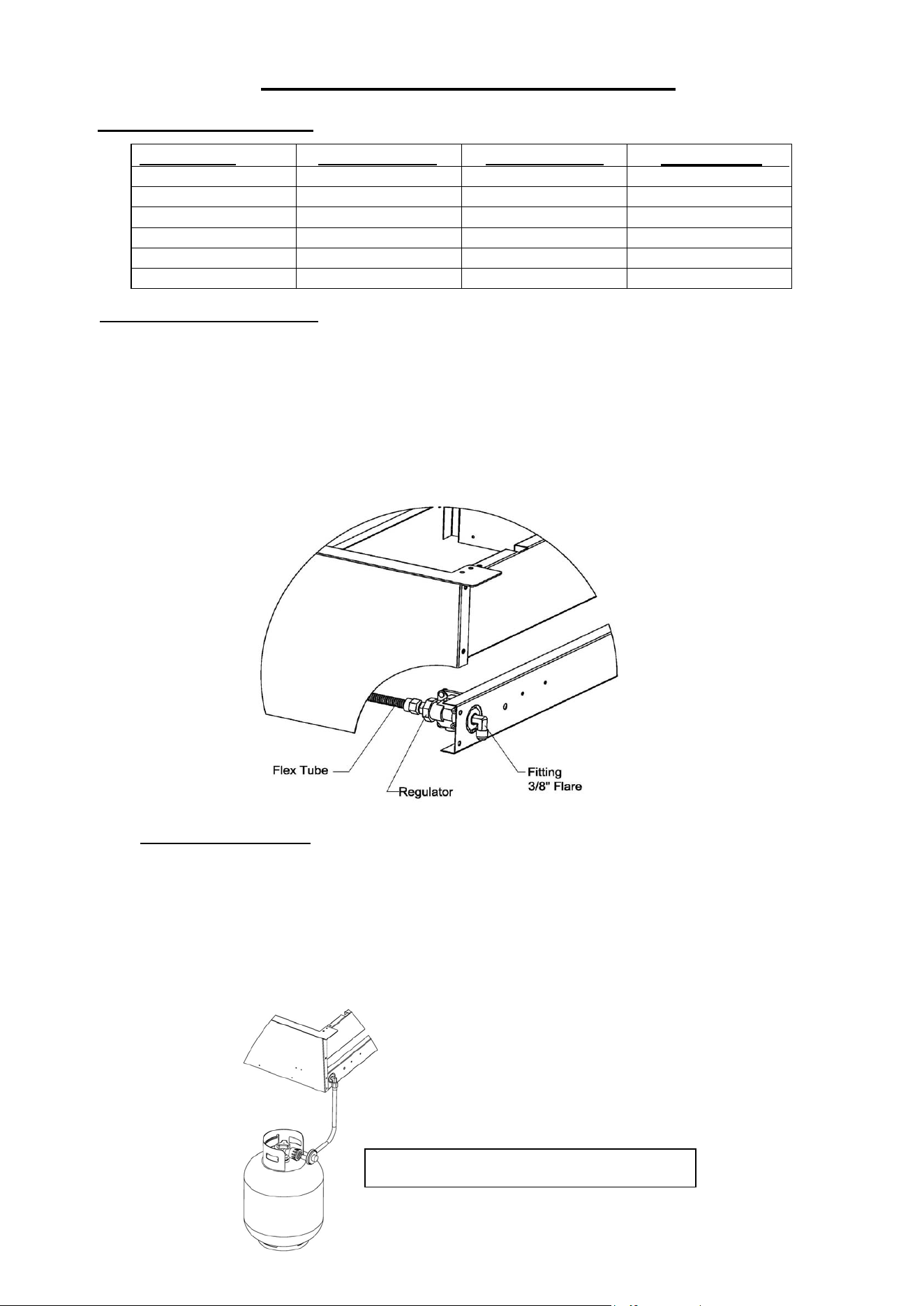
Purchase a standard 20 LB. LP tank with QCC – 1 fitting, and an
approved hose and low pressure regulator like the RCS: RONHK. (Available
From Your RCS Dealer) Assemble pipe/hose assembly as shown (not
included).
Grill Model Main Burners
Rear Burners
Total BTU’s
RJC26A 12,000
-
36,000
RJC32A / RJC32AL
12,000
12,000
60,000
RJC40A / RJC40AL
12,000
12,000
72,000
RON30A 15,000
12,500
57,500
RON38A 15,000
12,500
72,500
RON42A 15,000
12,500
72,500
The RONHK hose kit is shown here.

To connect, insert the regulator inlet into the tank valve and turn the black coupler clockwise until
the coupler tightens up. DO NOT OVER TIGHTEN THE COUPLER.
After completion of assembly, make sure all appliance control valves are OFF then turn the
propane tank supply valve on and then turn the control valves on the grill to the ‘HI/IGN’ position for
approximately 5 seconds to purge the line of air out of the gas line. After 5 seconds, you may turn on the
other burners.
Inspect the gas hose before each use of the appliance. If it is evident there is abrasion or wear, or the gas
hose is cut, it must be replaced prior to the appliance being put into operation. The replacement gas
hose assembly shall be that specified by the manufacturer.
To disconnect the propane tank from the appliance, turn the tank valve off. Hold the coupler sleeve and
turn counter clockwise. The inlet line will be disengaged.
If the appliance is not in use, the gas must be turned off at the supply cylinder. Propane cylinders
must be stored outdoors out the reach of children and must not be stored in a building, garage or any
other enclosed area.
A dented, rusty, outdated or damaged propane cylinder must be replaced immediately.
Check for leaks with a soapy water solution every time the cylinder is
replaced or reconnected. All leaks must be corrected immediately.
NEVER USE AN OPEN FLAME TO CHECK FOR LEAKS. ALL GAS CONNECTION POINTS
SHOULD BE TESTED FOR LEAKS AFTER INSTALLATION PRIOR TO FIRST USE OF THE
GAS APPLIANCE(S).
Before installing an appliance in any island cut out, make sure that the opening is not larger than the
outside frame of the appliance unit. The appliance should rest on the lip of the frame. (See cut out
recommendations on page 15).
Pay careful attention to the location of the gas line. It should be routed away from sources of heat, sharp
edges, and aggressive surfaces and should make as few bends as possible.
Ensure the gas line connection will be accessible when the appliance is installed. A safety shutoff valve is
required at this gas connection point. Before installing the grill into the island cutout, the main burner
cotter pins on the cutlass and cutlass pro series grill may be removed for convenience of service,
adjustments, and maintenance in the future. The premier series uses screws and are required.
LP Tank Requirements:
The L.P. gas cylinder must be constructed and marked in accordance with the specifications
for L.P. gas cylinders of the U.S. Department of Transportation (DOT) and designed for use with a
QCC-1 quick disconnect system only.
The cylinder must be provided with a shut-off valve terminating in an L.P. gas supply cylinder
valve outlet specified, as applicable, for connection Number QCC-1.
The cylinder must be provided with a listed overfilling prevention device. The pressure regulator must
be used. Replacement of pressure regulators and hose assemblies can be purchased from authorized
dealers.
The cylinder supply system must be arranged for vapor withdrawal. Make sure the LP cylinder has a
collar to protect the cylinder valve. Do not store a spare LP gas cylinder under on near this appliance.
Never fill the cylinder beyond 80 percent full.
12| P ag e
Installation Location for All Models
Choose a location where the flow of air on the front or rear of the grill is not obstructed.
Due to high temperatures, place the grill out of traffic and keep away from clothing, furniture, or any
combustible materials. Keep the gas line connection as short as possible. Do not install in recreational
vehicles/mobile homes, trailers, boats, etc.
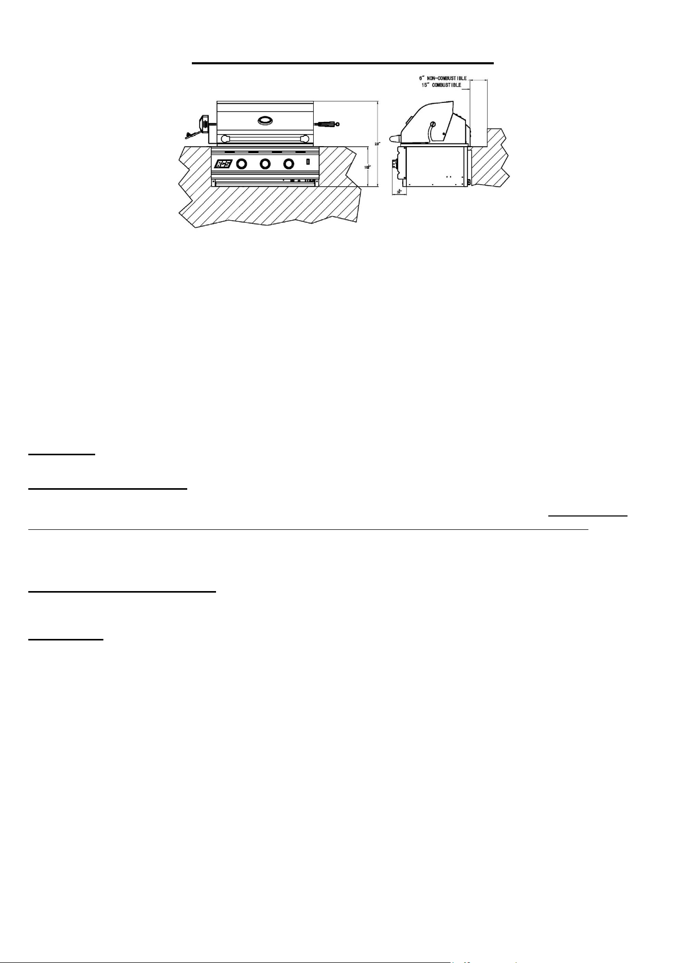
A minimum of five(5) foot clearance is required between the counter top and the overhead non-
combustible construction. When installed under combustible overhead construction, the area above the
cooking surface of the grill must be covered with an appropriately-sized (At least 6" wider than the grill cooking
surface, a minimum of 1200 CFM and designed for outdoor use) exhaust hood. The exhaust hood provides the
protection for combustible overhead construction.
Clearances
Combustible Construction
Minimum horizontal clearance from sides and back of the unit to adjacent vertical combustible
construction extending above top of unit, 24 inches from side and 15 inches from back. Do not locate
under any overhead combustible construction unless a properly-sized vent hood is installed. If island
frame construction is built out of a combustible material, you must use an insulated liner jacket
from RCS.
Non-Combustible Construction
Sides of the grill can be 0” from non-combustible wall, below the cooking surface.
Wind Guard: WARNING! Your RCS grill should NOT be installed with the back of the grill facing
frequent, prevailing winds like a large body of water or open space unless there is a substantial back
splash or some way of blocking the wind. In some rare occurrences, when there is a strong wind
present, it can cause heat that is normally exhausted through the rear ports to be forced back into
the grill and may cause overheating of the control panel and controls. Damage caused by this type
of installation is not covered by warranty. If you are experiencing this problem, please contact RCS to
order a wind guard which may or may not solve your problem but may be a possible alternative to
changing the location of the grill if it has been installed with the rear of the grill facing the prevailing winds.
13 | page
14 | P ag e
BEFORE
AFTER
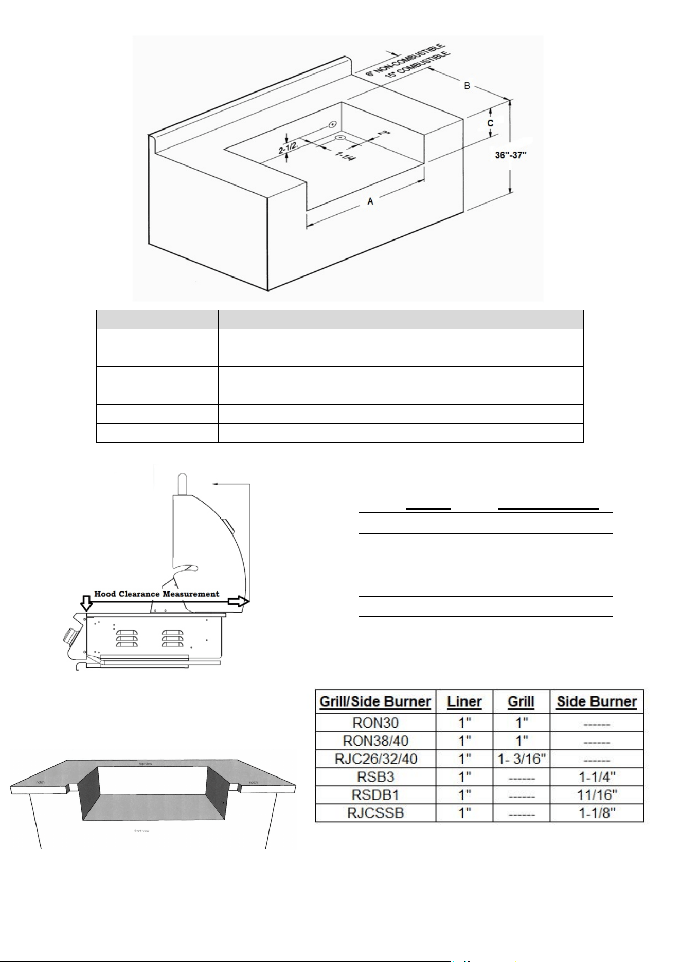
Built-in Installation
For non-combustible cabinet enclosure installation only. Follow the cut-out dimensions
as shown. ALL outdoor kitchen cabinets MUST include ventilation. There must be
12 square inches of opening for each (running) 4 feet of counter top. See Item # RVNT1
for approved vents. In the event of an installation in a combustible (wooden) cabinet,
you must use an insulated jacket available from RCS.
Model/Part Number
RWGM - RJC26A/RJC32A/RJC32AL/RON30A
RWGL - RJC40A/RJC40AL/RON38A/RON42A
15 | P ag e
Model
“A” Width
“B” Depth
“C” Height
RJC26A
23 1/2”
21”
8 ¼”
RJC32A /RJC32AL
30 5/8”
20 3/4”
8 ¼”
RJC40A / RJC40AL
37 3/4”
21”
8 ¼”
RON30A
33”
20”
11”
RON38A
41 1/4”
20”
11”
RON42A
45”
20”
11”
Model
Hood Clearance
RJC26A
25”
RJC32A / RJC32AL
25”
RJC40A / RJC40Al
25”
RON30A
23”
RON38A
23”
RON42A
23”
Notch Cut Outs for Appliance Control Panel
Note: these notch dimensions above refer to the width
(left to right) not depth of the cut. The depth is
determined by the amount of lip on the island top back
to the face of the island base.
REAR HOOD CLEARANCE
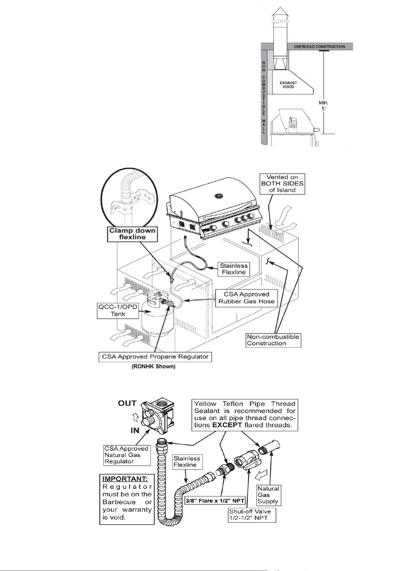
Exhaust Hood Requirements
When using an exhaust hood, the area above the cooking
surface of the grill must be covered with a hood larger
than the cooking area of the grill, AND with a minimum of
1200CFM (cubic feet per minute) for proper outdoor
application.
Combustible Overhead Construction: Exhaust hood
required.
Non-Combustible Overhead Construction: Exhaust hood
recommended.
16 | P ag e
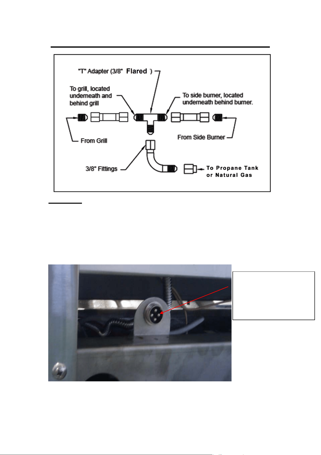
If adding a side burner to your connection:
Electrical
Electrical outlet for Rotisserie motor must be installed to the left side of the grill.
The outdoor cooking gas appliance, when installed, must be electrically grounded in
accordance with local codes or, in the absence of local codes, with the National
Electrical Code, ANSI/NFPA 70, or the Canadian Electrical Code, CSA C22.1.
Keep any electrical supply cord and fuel supply hose away from any heated surface.
HALOGEN LIGHT: The RJC32AL, RJC40AL, RON30A, RON38A & RON42A are
provided with a low-wattage transformer. Connect 115V power to the grill.
USE the transformer provided! Replacement light bulb is 12v, 5 watts.
17 | P ag e
On the RON30a, RON38a
and RON42a, this plug is
specially used for
connecting the optional
RDB1EL side burner.
18| P ag e
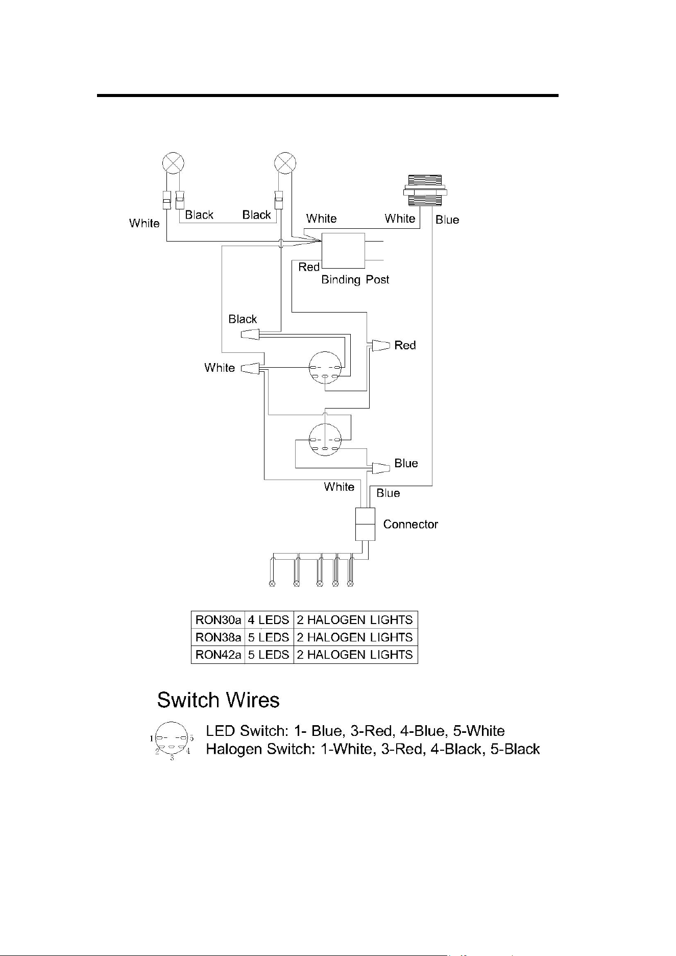
Cutlass Pro Electrical Wire Diagram
Coector
Black
ite
C32AL
C40
Coector
Black
Red
ite
Switch
Red
Black
ite
5 LS
6 LS
ite
Black
Coector
2 L LIGS
2 LEN LIGS
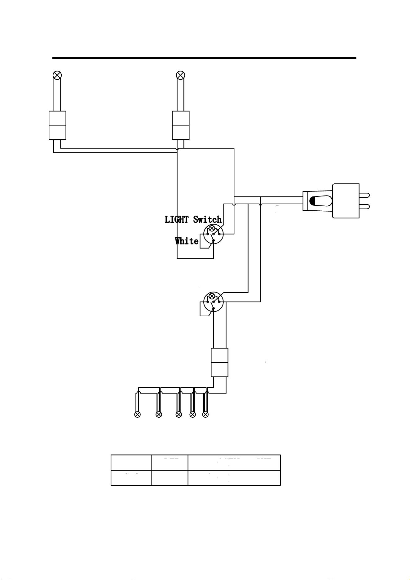
Premier Series Electrical Wire Diagram
19 | P ag e
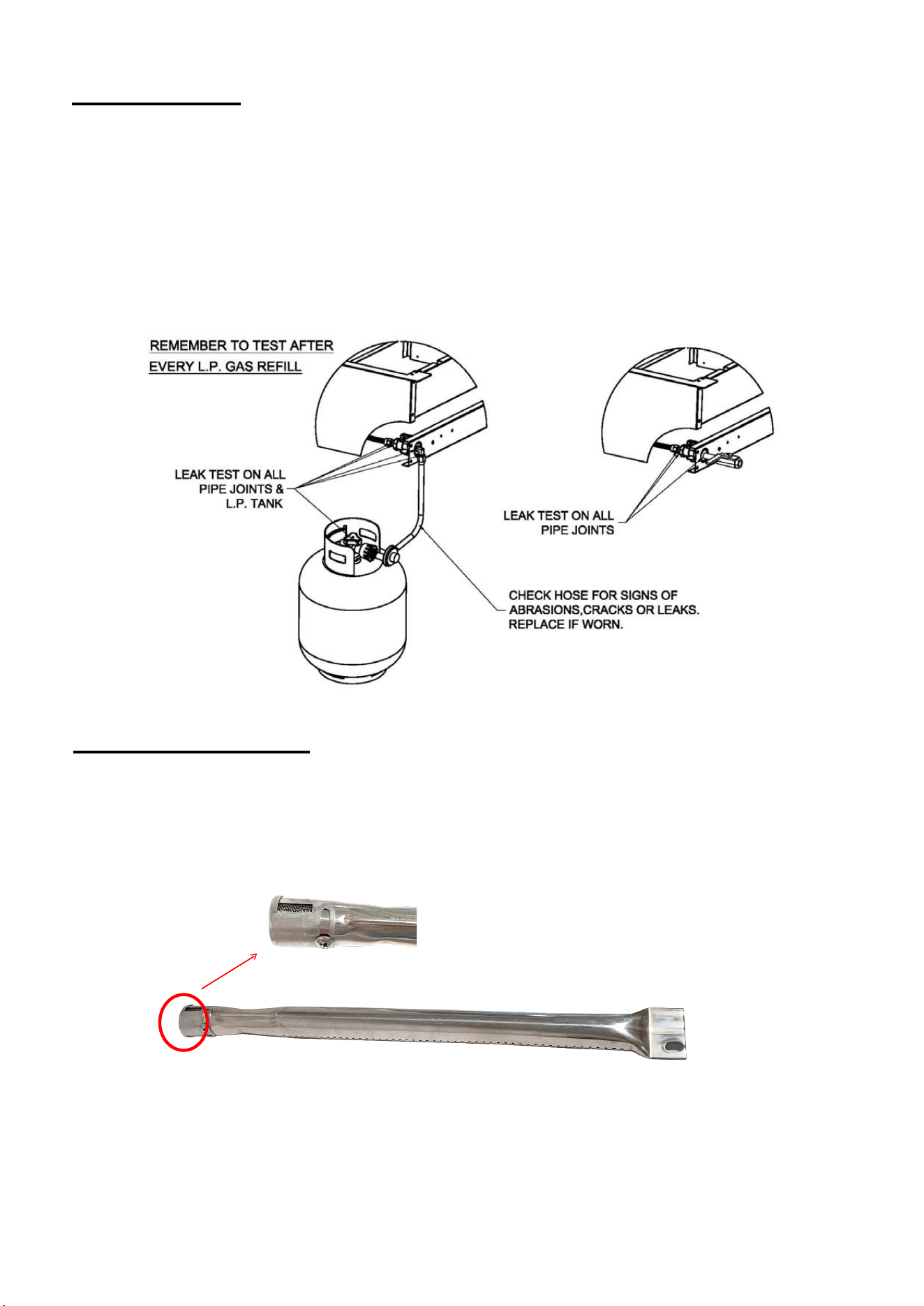
Leak Testing
NEVER USE AN OPEN FLAME TO CHECK FOR LEAKS.
All gas piping and connections must be tested for leaks after installation or service. All leaks
must be corrected immediately. Remember-before exchanging an empty
bottle for a new one,
make sure all control valves are in the “off” position.
With the LP regulator connected to tank and grill and the grill knobs turned to OFF. Open the
valve on the tank. Test for leaks by applying liquid soap solution to all joints. Bubbles forming
indicate gas leak. Fix gas leak before continuing use.
Burner Adjustments
Every grill is thoroughly checked for proper lighting and burner flame pattern. Conditions at the
location may necessitate minor adjustment of the burner air intake, if the flames are not
steady/stable as shown in the figure.
The flame should be full length of the burner, blue and stable. The air intake (if applicable) should be
adjusted ONLY if the flame is lifting off of the ports or has noticeable amounts of yellow in
the flame.
20 | P ag e

If flame is lifting, remove the front panel to access the burner front (air shutter)
then turn the
air shutter clockwise reducing this intake. The screw should be loosened before turning the air
shutter.
If the flame has more yellow than blue, the air shutter should be turned counter clockwise
allowing more air in. This will stabilize the flame. Make sure to tighten the screw after
adjustments are made.
In order to provide gas to the burner, the orifice must be inside the burner venturi opening.
Check to ensure that the burner is properly secured at the front and back.
Lighting Instructions
Before Lighting:
• Check gas line/hose for signs of wear, abrasion or cuts. If evidence of
deterioration is visible,
replace the part prior to use.
• If you smell gas, check for leaks. If odor continues, immediately call for service. Keep your
face and body away from the grill top when lighting.
Grill Burner Lighting
1. Open lid before lighting. Make sure all burners are in the
‘OFF’ position.
2. Push and turn burner knob to ‘HI/IGN’ position. You will hear a "Click".
3. The pilot flame will ignite at this point, lighting the main burner.
4. Continue to hold the knob in until you have ignition.
5. If there is no ignition after 2-3 seconds, turn the knob back to the “OFF” position and repeat
steps 2-4.
1.
Follow steps 2-3
2.
Place either a burning long-barrel butane lighter or a burning long-stem match near the
manual flash tube to the front of the grill at the cooking surface. For back burners, hold
the flame against the surface of the back burner.
3.
Place ignition source over flash tube then rotate grill knob to high while holding ignition over
flash tube for five seconds.
4.
If the burner does not light within five (5) seconds of turning the control knob, immediately
depress the knob and turn the control knob to off position. Wait five (5) minutes before
repeating steps 2-4 of the MANUAL LIGHTING instructions.
5.
If the burner does not light after several attempts, immediately close all gas valves and
consult an authorized service technician.
Caution: Always wait five (5) minutes for gas to clear after any unsuccessful
lighting attempts.
Manual Ignition
Rotisserie Burner Lighting
1. Open lid before lighting. Make sure all burners are in the ‘OFF’ position.
2. Be sure to remove the upper grid in the back of your grill PRIOR to lighting the rear burner!
3. Push in and hold the control knob for 5 seconds then turn the rear rotisserie control knob to
the “on” position. While there, you’ll hear the igniter “click” This should light the rear burner.
4. If you do not see the rear burner ignite, repeat step 3. You may also see the video online at
RCSGasGrills.com.
21 | P ag e

Optional Infred Burner
1. To install the optional infrared burner, begin by removing the far left cooking grid, flame tamer
and zone divider, if applicable.
2. Remove conventional burner by first removing the cotter pin or screws that hold the burner in
place (unless they were removed prior to installation), located on the bottom rear of the burner
and located inside the rear of the grill body. With the cotter pin or screws removed, remove the
conventional burner by lifting up then pulling the burner to the rear of the grill housing.
3. Place the infrared burner in place and reattach the screws that hold the burner in place,
leaving off the flame tamer. Ensure the burner is seated appropriately around the valve so that
gas flows into the burner.
4. If applicable replace the heat zone divider and cooking grid. Do not use this burner with the
flamer tamer reinstalled above the burner.
Preheating the Infrared Burner
Always preheat the entire appliance before cooking. If the appliance is already hot from cooking,
you should still preheat the infrared burner for 3 minutes with hood open. Never place food over
the burner until it is fully preheated to avoid clogging the tiny ports and damaging the burner from
grease drippings and food particles.
Infrared Burner Cleaning
To keep your infrared burner operating at maximum performance after each use, turn it on HIGH
for 5 minutes with the hood open. This allows any food particles or grease drippings to burn
away. Once your appliance has cooled completely, use a soft brush or vacuum to remove any
ash accumulation on the burner if necessary.
Operation
DO NOT LEAVE YOUR GRILL UNATTENDED WHILE IN OPERATION.
Grill:
Grill burners are controlled individually with control knobs. After lighting, turn the knob to HI,
LO or in between as desired. Turn on as many burners as required. The lid may be closed
during grilling. Keep the lid in closed position during the pre-heat period.
If you have installed an optional infra-red burner in your grill, you must leave the lid
open while the infra red burner is in use, due to the intense heat it will generate! If lid is
closed the heat can cause the housing to warp and voiding your warranty.
Rotisserie:
(Not included with all models) Plug in the motor power cord to a properly grounded receptacle.
Rotisserie cooking can be done with grill burners as well as with the Rotisserie
burner ‘ON’. KEEP THE MOTOR STORED INDOORS WHEN NOT IS USE.
Be sure to remove the upper grid in the back of your grill PRIOR to lighting the rear burner!
The rotisserie skewers slide in from the side with the tip sliding into the motor shaft adapter.
The slot on the handle side should be on the side support panel edge.
Use the prongs to hold the meat. Tighten thumbscrew on the prong hubs to secure in place.
When ready, turn the switch on the motor box to the ‘ON’ position. The spit rod will rotate
slowly.
Stop the motor before removing the skewer or spit rod.
22 | P ag e

Cleaning and Maintenance
Cleaning: Your grill works better and lasts longer if properly cleaned and maintained.
Clean the grill after each use. Turn grill off before starting to clean. Protect your hand
with a good mitt when cleaning the hot grill. Use a wire brush, dip in water and scrub
the cooking grids to soften and loosen food spills. The food spills will fall into the crumb
pan. Burn off excess food debris and marinades for 15 minutes after cooking. Do not
use Aerosol cleaners on hot grill surface. Chemicals may produce noxious fumes
and may ignite on contact with the hot surface.
Shield: Burner shields are made up of stainless steel. Occasionally,
after allowing the shields to cool down, remove and soak them in water with a mild soap
or detergent. Replace when dry.
Briquettes: If your grill uses briquettes, it is recommended to occasionally use a wire brush to
gently clean them.
Crumb Tray / Grease Pan: Empty grease pan as required to prevent overflowing. After use,
remove the pan and brush off the contents. Clean with hot water and soap or detergent. NEVER
line drip the pan with any type of foil!
All stainless steel parts should be cleaned with a mild soap or detergent or with a liquid cleanser
especially made for stainless steel. Never attempt to clean stainless steel with steel
wool, abrasive cloths or powders.
Maintenance
Keep outdoor cooking gas appliance area clear and free from combustible materials, gasoline
and other flammable vapors and liquids.
Do not obstruct the flow of combustion and air ventilation. Keep the ventilation opening(s) of the
cylinder enclosure free and clear from debris.
There are many different stainless steel cleaners available. Always use the mildest
cleaning procedure first, scrubbing in the direction of the grain. To touch up noticeable
scratches in the stainless steel, sand very lightly with dry 100 grit emery paper in the direction
of the grain.
Specks of grease can gather on the surfaces of the stainless steel and bake on to the surface
and give the appearance of surface rust. Surface rust is caused by using steel wool or
steel bristle brushes to clean the surfaces. Never use steel wool or steel bristle brushes on the
stainless steel surfaces. It can also be caused by harsh chemicals used in the area of
the grill, like common pool chemicals or acid used to wash down patios or decks. NEVER
store chemicals of ANY kind in or near your grill! Surface rust may also be caused by other
forms of contaminants found in the air or as a result of foreign matter introduced to the grill. For
removal of most types of surface rust, use a slightly abrasive pad (Scotch Brite is good) in
conjunction with a stainless steel cleaner. Bar Keepers Friend is another excellent
product. Always rub in the direction of the grain. Surface rust is not covered under the
warranty.
Routinely have a professional barbecue cleaning company detail the barbecue for best results
and longevity.
The burners, control area, crumb pan, etc. should be kept clean at all times. During prolonged
non-use of the grill, spiders & insects can nest in areas that will adversely affect the functioning of
the grill. Check burner inlets, orifice hood (gas inlet to burner), igniter, ignitors, etc. thoroughly and
clean before use.
23 | P ag e
24| P ag e
Fuel (Gas) Conversion Instructions for RCS grills.
This should only
be performed by a licensed gas professional
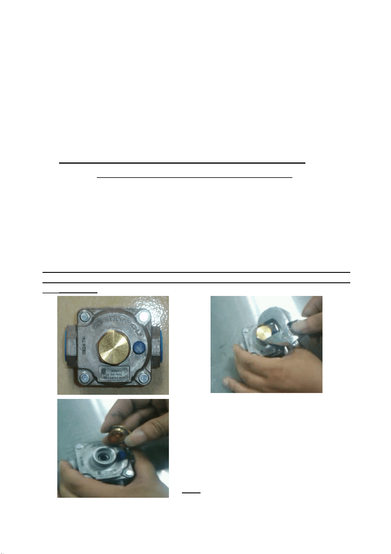
Gas regulator:
Currently all grills are supplied with a gas regulator installed. When converting the gas
application you must also convert the regulator by removing the large nut on the front of the
regulator, pulling out the plastic orifice, flipping it over and re-installing it. Tighten the large nut
and you’re ready to go. (This step does not apply to the LP hose and regulator set, only the
separate regulator that comes with the grill. You must flip this plunger when converting a
propane grill from natural gas along with installing a low pressure propane hose and regulator).
In order, the regulator must be installed and converted first in order to achieve
the proper pressure to test the conversion steps 1-10 and back burner
conversion 1-3 below. To adjust the low flame setting if necessary, see next
page………
Unscrew and remove this brass cap. This exposes
the plastic plunger
Pull off and flip over the plastic plunger and
replace in the hole. Large side down converts
the regulator to LP by compressing the interior
spring.
Replace the brass cap and you are done!!!
Note: the plunger snaps in and out of the cap.
Important Note: For Locations Near Coastal Areas and Pools
#304 stainless steel materials used in the construction of your cutlass PRO series grills are highly
rust resistant, however, chlorine in the air from swimming pools or the salt from sea air may cause
surface rust to appear and even create some pitting if left on the product. Here are a few tips to
avoid this:
• Regularly wipe down the exterior surfaces with a damp cloth (micro fiber towels work
well with grain of stainless)
• Allow the surfaces to dry before installing the cover. Do not cover a damp grill
• In extreme environments apply a rust inhibitor which leaves a microscopic protective
layer on the grill
• For seasonal storage use the product referred to above, ensure the grill is dry, then
cover and secure the cover to minimize the amount of damp air getting to the
surfaces
25| P ag e
Fuel Conversion of
Main Burners:
1- Determine the existing gas type (LP or Natural gas). The method of changing gas
types is similar for natural gas or propane gas.
2- You must remove all grates and burner covers to expose the main burners in the grill.
3- On the bottom rear of each burner may be a cotter pin or screws attaching burners
to the grill housing. Remove cotter pins or screws.
4- Slide burner to the rear of the grill and up. Repeat for each burner.
5- Where the burner was located going through a hole in the basin and connecting to
the valve is now evacuated space.
6- Inside the space you will find the end of the valve (front of grill), with an orifice (brass
fitting), screwed into the end of the valve stem.
7- Remove the orifice with a 1/4" socket and extension. (These are extremely fragile
when turning. Be extremely gentle when removing).
8- Replace with new orifice, (repeat for all burners). When re-installing orifice do not
over tighten or you will strip the brass fitting. Little pressure is needed!!!
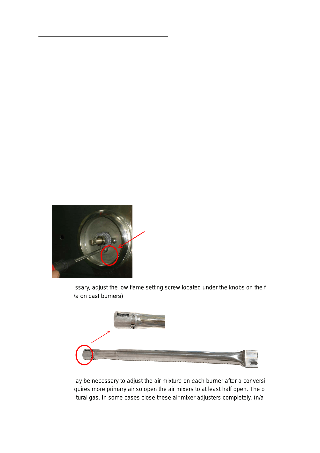
9- Replace burners and test for proper flame height. Flame should stand at
approximately ½” to 1” on low and 1.5” to 2” on high. (to adjust the low flame setting
simply light the grill on the low setting and adjust the screw which is located under the
knob on the front of the valve as per diagram below.)
10- Replace burner covers and grates.
11-If necessary, adjust the low flame setting screw located under the knobs on the front of the
v
alve. `(n/a on cast burners)
Note: It may be necessary to adjust the air mixture on each burner after a conversion. Typically
LP gas requires more primary air s
o open the air mixers to at least half open. The opposite is
true for natural gas. In some cases close these air mixer adjusters completely. (n/a on cast
burners)
Low flame setting screw

Rot
isserie Burner
Conversion:
1- Remove the back panel at the rear of the grill, this will expose the V shaped or pyramid
shaped brass orifice.
2- Replace with new orifice.
3- Replace rear panel.
Trouble Shooting: Problem and Solution
Burner will not light
• Check gas supply to burner by manually lighting the burners.
• See electrode for visible damage, replace if damaged.
Improper Burner
Flame
• Check burner gas inlet area for blockage
• Check orifice hoods for any clogging and clean.
• Adjust air shutter, if necessary.
• Check pressure if flame is too low or too high.
• Check gas supply tank (LP) if running low.
Light is not ON
• Connect 115V power at rear. Turn switch ON.
• Make sure the transformer was used in installation and your grill was NOT hooked up
directly to 115 volt power source.
• Check bulb. Replace if necessary.
• Check any GFCI plugs in line.
My knobs are hot and/or the control panel is blue and wiring is
burnt up. Sounds like a rear wind
issue. Do you have a back-splash or wind block? Do you live on a hill, lake or large open area?
Fire in the grill? Your grill may be grill is full of grease, or was? Have you cleaned it recently……or ever? Is
there foil in the clean-out tray? Not good, please remove it.
“My grill is covered with rust”. Do you have a pool nearby? Are chemicals stored under the grill? Do you live
on a coast or near it? Is the grill VERY new but the spots have occurred due to acid washing concrete? Are
the spots ONLY on the grill and not doors and drawers? Are the “spots” in a spray fashion? Occasionally this
occurs when the construction is still going on and the equipment is in the area. Chemicals (acids usually) are
sprayed on the brick or stone to clean it. The spots are surface rust and are not covered under warranty. We
recommend using Bar Keepers Friend to clean the spots off.
“My grill does not get over (blank) degrees” It is possible that you need a new heat indicator, perhaps the
original one is mis-calibrated. Are is your grill LP and you have it in a natural gas situation (or vice versa)?
See the manual regarding grill conversions. OR if your home builder installed your grill, you they may have a
flow-restricter in the line. An easy way to test this is to remove the cooking grids and grates/briquettes below
so you may observe the operation of the burners. Light one, notice the height of the flame which on high
should be 1 ½” to 2”. Then turn on a second burner then a third. The flame height should remain the same. If
not, you have a low-pressure situation and it is not the fault of the equipment, check with your builder.
“Rear burner won’t light” Solution: Visit the RCS website, under documents watch the video about how to light
your rear burner. GREAT video there.
There are more great FAQ's, documents, and videos on our website www.RCSGasGrills.com.
26 | P ag e
27| P ag e
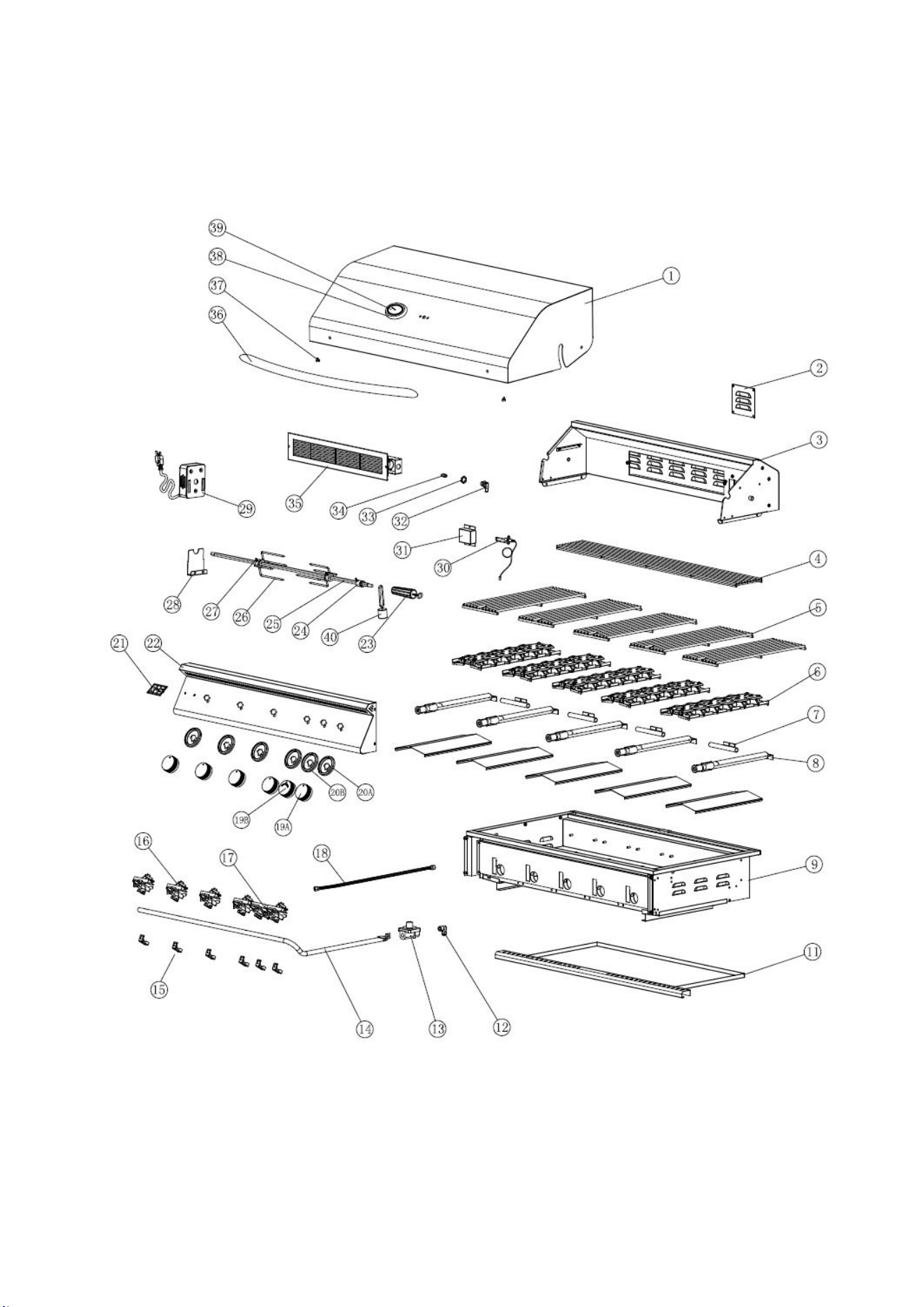
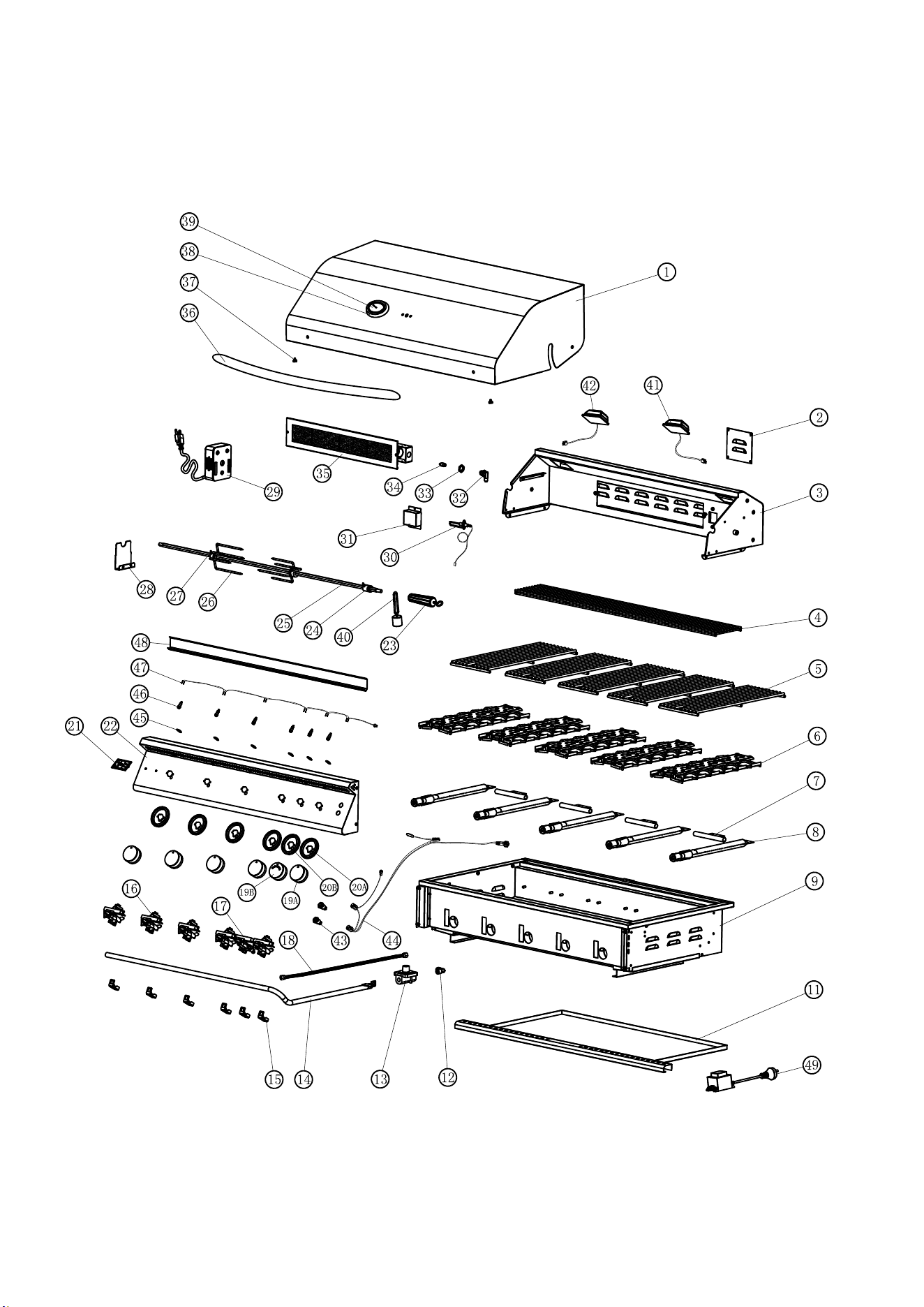
RJC26A/RJC32A/RJC40A Enlarged View
28 | P ag e
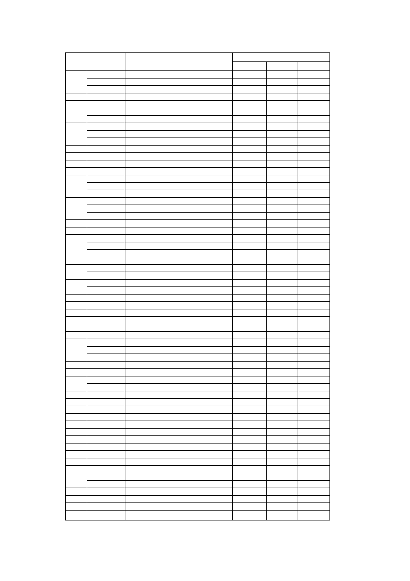
RJC26A/RJC32A/RJC40A Parts List
ITEM
PART NO.
DESCRIPTION
QTY.
RJC26A RJC32A RJC40A
1
RJC001P
26"-TOP HOOD
1
RJC002P
32"-TOP HOOD
1
RJC051P
40"-TOP HOOD
1
2
RJC003P
ACCESS DOOR
1
1
3
RJC004P
26"-REAR HOOD
1
RJC005P
32"-REAR HOOD
1
RJC052P
40"-REAR HOOD
1
4
RJC006P
26"-WARMING RACK
1
RJC007P
32"-WARMING RACK
1
RJC053P
40"-WARMING RACK
1
5
RJC008P
TOP GRATE
3
4
5
6
RJC009P
BRIQUETTE TRAY
3
4
5
7
RJC010P
CROSSOVER TUBE
2
3
4
8
RJC011P
BURNER
3
4
5
9
RJC012P
26"-BASIN
1
RJC013P
32"-BASIN
1
RJC054P
40"-BASIN
1
11
RJC015P
26"-DRIP TRAY
1
RJC016P
32"-DRIP TRAY
1
RJC055P
40"-DRIP TRAY
1
12
RJC017P
90 DEGREE FITTING
1
1
1
13
RJC018P
REGULATOR
1
1
1
14
RJC019P
26"-MANIFOLD
1
RJC020P
32"-MANIFOLD
1
RJC056P
40"-MANIFOLD
1
15
RJC021P
VALVE LATCH
3
5
6
16
RJC022P
MAIN VALVE - NATURAL GAS
3
4
5
RJC060P
MAIN VALVE - PROPANE
3
4
5
17
RJC023P
IR BURNER VALVE - NATURAL GAS
1
1
RJC061P
IR BURNER VALVE - PROPANE
1
1
18
RJC024P
IR BURNER FLEX TUBE
1
1
19 A
RJC025P
KNOB-MAIN VALVE
3
4
5
19 B
RJC048P
KNOB-IR BURNER VALVE
1
1
20 A
RJC026P
KNOB BEZEL-MAIN VALVE
3
4
5
20 B
RJC049P
KNOB BEZEL-IR BURNER VALVE
1
1
21
RJC027P
LOGO PLATE
1
1
1
22
RJC028P
26"-CONTROL PANEL
1
RJC029P
32"-CONTROL PANEL
1
RJC057P
40"-CONTROL PANEL
1
23
RJC030P
ROTISSERIE HANDLE (OPTIONAL)
1
1
24
RJC031P
SPIT COLLAR (OPTINAL)
1
1
25
RJC032P
32"ROTISSERIE SPIT (OPTIONAL)
1
RJC058P
40"ROTISSERIE SPIT (OPTIONAL)
1
26
RJC033P
SKEWER FORK (OPTIONAL)
1
1
27
RJC034P
THUMB SCREW (OPTIONAL)
3
3
28
RJC035P
MOTOR BRACKET (OPTIONAL)
1
1
29
RJC036P
ROTIESSERIE MOTOR (OPTIONAL)
1
1
30
RJC037P
IR BURNER IGNITION WITH WIRE
1
1
31
RJC038P
IR BURNER IGNITION HOUSE
1
1
32
RJC039P
IR BURNER ELBOW FITTING
1
1
33
RJC040P
IR BURNER JOINT NUT
1
1
34
RJC041P
IR BURNER ORIFICE
1
1
35
RJC042P
IR BURNER
1
1
36
RJC043P
26"-HOOD HANDLE
1
RJC044P
32"-HOOD HANDLE
1
RJC059P
40"-HOOD HANDLE
1
37
RJC045P
RUBBER STOPPER
2
2
2
38
RJC046P
TEMP GAUGE BEZEL
1
1
1
39
RJC047P
TEMP GAUGE
1
1
1
40
RJC050P
BALANCE WEIGHT
1
1
RJC32AL / RJC40AL Enlarged View
29 | P ag e
RJC32AL RJC40AL
RJC002P 32"-TOP HOOD 1
RJC051P 40"-TOP HOOD 1
2 RJC003P ACCESS DOOR 1 1
RJC062P 32"-REAR HOOD 1
RJC063P 40"-REAR HOOD 1
RJC007P 32"-WARMING RACK 1
RJC053P 40"-WARMING RACK 1
5 RJC008P TOP GRATE 4 5
6 RJC009P BRIQUETTE TRAY 4 5
7 RJC010P CROSSOVER TUBE 3 4
8 RJC011P BURNER 4 5
RJC064P 32"-BASIN 1
RJC065P 40"-BASIN 1
RJC016P 32"-DRIP TRAY 1
RJC055P 40"-DRIP TRAY 1
12 RJC017P 90 DEGREE FITTING 1 1
13 RJC018P REGULATOR 1 1
RJC020P 32"-MANIFOLD 1
RJC056P 40"-MANIFOLD 1
15 RJC021P VALVE LATCH 5 6
RJC022P MAIN VALVE-NATURAL GAS 4 5
RJC060P MAIN VALVE-RPOPANE 4 5
RJC023P IR BURNER VALVE - NATURAL GAS 1 1
RJC061P IR BURNER VALVE - RPOPANE 1 1
18 RJC024P IR BURNER FLEX TUBE 1 1
19A RJC066P KNOB-MAIN BURNER 4 5
19B RJC067P KNOB-BACK BURNER 1 1
20A RJC026P KNOB BEZEL-MAIN VALVE 4 5
20B RJC049P KNOB BEZEL-IR BURNER VALVE 1 1
21 RJC027P LOGO PLATE 1 1
RJC068P 32"-CONTROL PANEL 1
RJC069P 40"-CONTROL PANEL 1
23 RJC030P ROTISSERIE HANDLE (OPTIONAL) 1 1
24 RJC031P SPIT COLLAR (OPTINAL) 1 1
RJC032P 32"ROTISSERIE SPIT (OPTIONAL) 1
RJC058P 40"ROTISSERIE SPIT (OPTIONAL) 1
26 RJC033P SKEWER FORK (OPTIONAL) 1 1
27 RJC034P THUMB SCREW (OPTIONAL) 3 3
28 RJC035P MOTOR BRACKET (OPTIONAL) 1 1
29 RJC036P ROTIESSERIE MOTOR (OPTIONAL) 1 1
30 RJC037P IR BURNER IGNITION WITH WIRE 1 1
31 RJC038P IR BURNER IGNITION HOUSE 1 1
32 RJC039P IR BURNER ELBOW FITTING 1 1
33 RJC040P IR BURNER JOINT NUT 1 1
34 RJC041P IR BURNER ORIFICE 1 1
35 RJC042P IR BURNER 1 1
RJC044P 32"-HOOD HANDLE 1
RJC059P 40"-HOOD HANDLE 1
37 RJC045P RUBBER STOPPER 2 2
38 RJC046P TEMP GAUGE BEZEL 1 1
39 RJC047P TEMP GAUGE 1 1
40 RJC050P BALANCE WEIGHT 1 1
41 RJC070P INNER LIGHT-RIGHT SIDE 1 1
RJC071P 32''INNER LIGHT-RIGHT SIDE 1
RJC072P 40''INNER LIGHT-RIGHT SIDE 1
43 RJC073P LIGHT/LED SWITCH 2 2
44 RJC074P LIGTH WIRING 1 1
45 RJC075P FIXING PLATE-LED LIGHT 5 6
46 RJC076P LED LIGHT 5 6
RJC077P 32"LED WIRING 1
RJC078P 40"LED WIRING 1
RJC079P COVER PLATE-32"LED WIRING 1
RJC080P COVER PLATE-40"LED WIRING 1
49 RJC081P TRANSFORMER 1 1
47
48
QTY.
1
3
4
9
11
14
22
36
RJC32AL/RJC40AL Parts List
ITEM PART NO. DESCRIPTION
42
25
16
17
30| P ag e
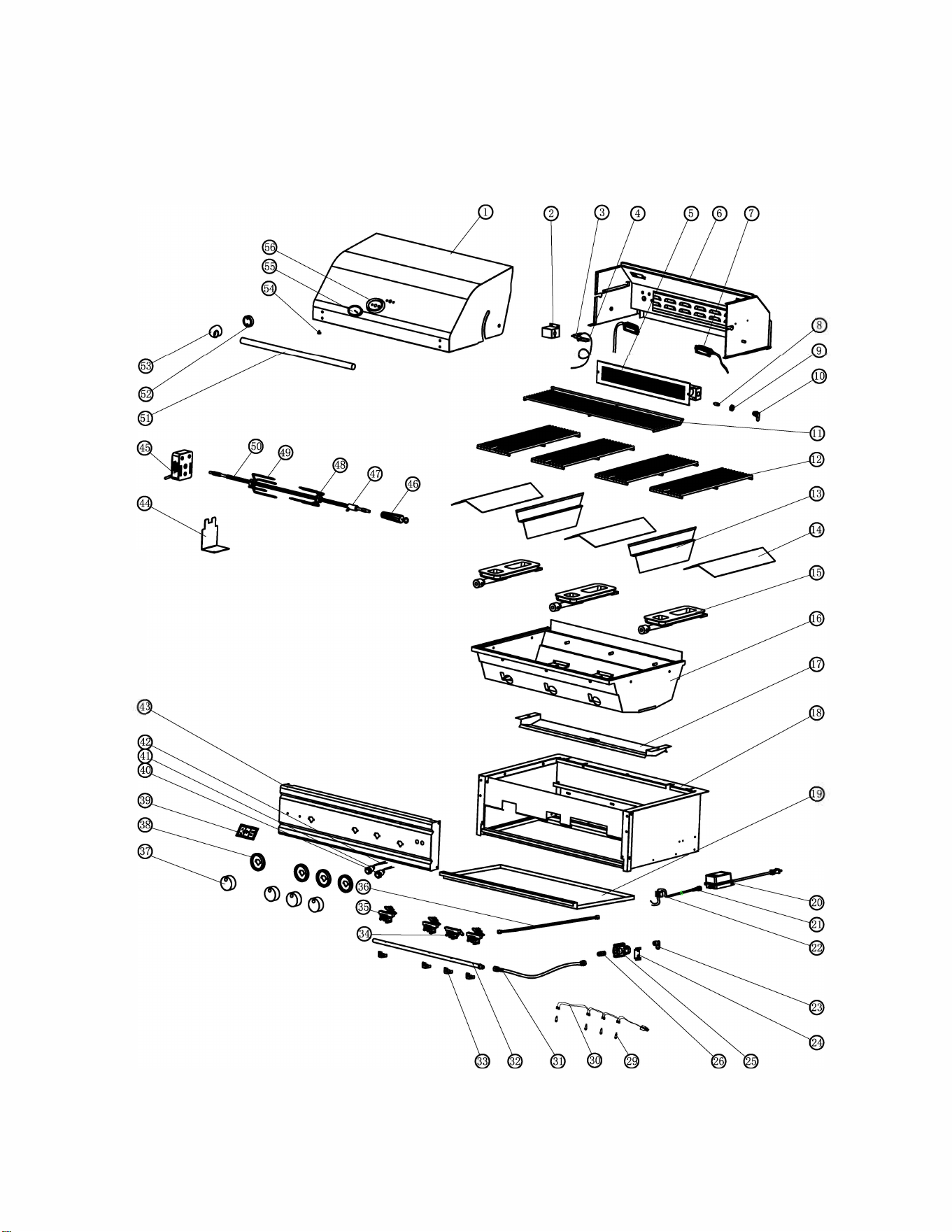
RON30a/RON38a/RON42a Enlarged View
c·
31
IP age
RON30a/RON38a/RON42a Parts List
ITEM PART# DESCRIPTION
QTY.
ITEM PART# DESCRIPTION
QTY.
RON30a RON38a RON42a RON30a RON38a RON42a
1
RON071 30”-TOP HOOD 1 29
RON130 LED LIGHT BULB 4 5
5
RON113 38”-TOP HOOD 1
30
RON099B 30 “-LED LIGHT WIRE 1
RON072 42”-TOP HOOD 1 RON121B 38 “-LED LIGHT WIRE 1
2 RON073 IGNITOR BRACKET-IR BURNER 1 1 1 RON122B 42 “-LED LIGHT WIRE 1
3 RON004 IGNITOR-IR BURNER 1 1 1 31 RON039 FLEX TUBE 500mm 1 1 1
4
RON074 30”-WIRE(1500mm) -IR BURNER 1
32
RON100 30 “-MANIFOLD PIPE 1
RON075 42”-WIRE(1700mm) -IR BURNER 1 1 RON123 38 “-MANIFOLD PIPE 1
5 RON076 30” -IR BURNER 1 1 1 RON101 42 “-MANIFOLD PIPE 1
6
RON077 30”-REAR HOOD 1 33 RON042 VALVE LATCH 4 5
5
RON114 38”-REAR HOOD 1 34 RON043 GAS VALVE-IR BURNER 1 1 1
RON078 42”-REAR HOOD 1
35
RON045 GAS VALVE(LP1.2)- MAIN BURNER 3 4 4
7 RON079 LIGHT 2 2 2 RON046 GAS VALVE(NG1.85)- MAIN BURNER 3 4 4
8 RON014
36”-ORIFICE(LP1.05)-IRBURNER 1 1 1 36 RON047 FLEX TUBE-IR BURNER 1050mm 1 1
1
36”-ORIFICE(NG1.6)-IR BURNER 1 1 1 37 RON102 CONTROL KNOB 4 5 5
9 RON015 ORIFICE ELBOW NUT 1 1 1 38 RON103 BEZEL 4 5 5
10 RON016 ORIFICE ELBOW 1 1 1 39 RON050 LOGO PLATE-RCS 1 1 1
11
RON080 30”-WARMING RACK 1 40 RON104 LIGHT SWITCH 1 1
1
RON115 38”-WARMING RACK 1 41 RON105 LED LIGHT SWITCH 1 1 1
RON081 42”-WARMING RACK 1
42
RON106 30 “-LIGHT WIRE 1
12
RON082 TOP GRATE-504*188*φ9 4 4 5 RON124 38 “-LIGHT WIRE 1
RON116 TOP GRATE-504*206*φ9 1 RON125 42 “-LIGHT WIRE 1
RON083 TOP GRATE-504*120*φ9 1
43
RON107 30 “-CONTROL PANEL 1
13 RON084 BURNER SEPARATOR 2 3 3 RON126 30 “-CONTROL PANEL 1
14 RON085 "V" BURNER SHIELD 3 4 4 RON108 42 “-CONTROL PANEL 1
15 RON086 CAST BURNER 3 4 4 44 RON055 BRACKET-MOTOR 1 1 1
16
RON087 30 “-INNER BASIN 1 45 RON056 MOTOR-ROTISSERIE 1 1
1
RON117 38 “-INNER BASIN 1 46 RON057 HANDLE-ROTISSERIE 1 1 1
RON088 42 “-INNER BASIN 1 47 RON058 SPIT COLLOR-ROTISSERIE 1 1 1
17
RON089 30 “-CRUMB TRAY 1 48 RON059 SCREW-SKWER FORK 3 3
3
RON118 30 “-CRUMB TRAY 1 49 RON060 SKWER FORK φ5.7 2 2 2
RON090 42 “-CRUMB TRAY 1
50
RON109 30 “-SKWER ROD 1
18
RON091 30 “-BASIN FRAME 1 RON127 38 “-SKWER ROD 1
RON119 30 “-BASIN FRAME 1 RON110 42 “- SKWER ROD 1
RON092 42 “-BASIN FRAME 1
51
RON111 30 “-HOOD HANDLE 1
19
RON093 30 “-GREASE TRAY 1 RON128 38 “-HOOD HANDLE 1
RON120 38 “-GREASE TRAY 1 RON112 42 “-HOOD HANDLE 1
RON094 42 “-GREASE TRAY 1 52 RON065B END CAP SPACER-HANDLE 2 2 2
20 RON032 TRANSFORMER 20W 1 1 1 53 RON066B END CAP-HANDLE 2 2 2
21 RON033 TRANSFORMER INLET CORD 1 1 1 54 RON067 RUBBER STOPPER 2 2 2
22 RON034 TERMIINAL BLOCK 1 1 1 55 RON068 TEMPERATURE GAUGE 1 1 1
23 RON035 90 DEGREE FITTING 1 1 1 56 RON069 TEMPERATURE GAUGE BEZEL 1 1 1
24 RON095 REGULATOR BRACKET 1 1 1
25 RON037 NG REGULATOR 1 1 1
26 RON038 NG FLARE FITTING 1 1 1
32
IP age

33
IP age
Renaissance Cooking Systems Product Warranty
RCS is proud to provide the industries most comprehensive warranty program.
All RCS Cutlass Pro Series Grills, Cutlass and Cutlass Pro side burners, Valiant doors and
drawers are now warrantied to be free from manufacturer defects for the lifetime of
the original owner.
All RCS Premier Series Grills and side burners are warrantied to be free from
manufacturer defects for 15 years to the original owner.
All other products carry a one-year warranty to the original owner.
This RCS warranty is effective for product sales beginning January 1st, 2020.
For service assistance, please reach out to us at the email address below. You may
also check our website for lots of great information on using, servicing, or cooking
on your new RCS grill.
This warranty excludes normal surface corrosion, discoloration, surface scratches and
surface rust which may occur. Improper maintenance, salt spray, chemicals, pesticides
will affect the look and integrity of the components of this grill. RCS will not be
responsible for any damage caused as a result of not following owner’s manual
instructions. This non-transferrable warranty is limited to the replacement of original
(one-time) defective parts, does not include shipping and labor to remove or install
replacement parts, if necessary. The owner must retain and submit their original
receipt with any warranty claim to receive warranty parts. The warranty applies to the
original owner only. Coverage is for residential use only, no commercial applications
apply. No registration required.
For more information, questions or assistance please contact us at:
RCSGasGrills.com ~ [email protected]
