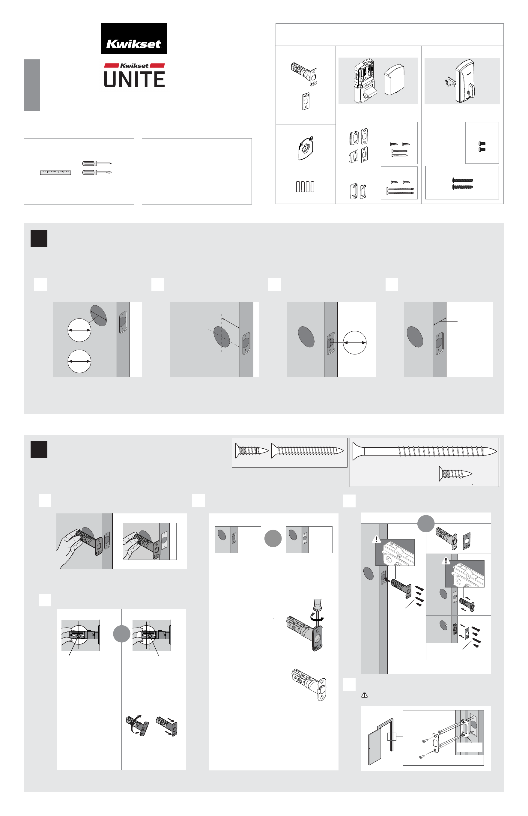
If drilling a new door, use the supplied template and the complete
door drilling instructions available at www.kwikset.com/doorprep.
Note: Additional door preparation may be
required for doors with 1-1/2 in (38 mm) holes.
Consult the deadbolt drilling instructions at
www.kwikset.com/doorprep.
or
backset
Measure to conrm that the hole in
the door is either 2-1/8 in (54 mm) or
1-1/2 in (38 mm).
Measure to conrm that the backset is
either 2-3/8 or 2-3/4 in (60 or 70 mm ).
60 or 70 mm
2-3/8 or 2-3/4 in
35 – 44 mm
1-3/8 – 1-3/4 in
Measure to conrm that the hole in
the door edge is 1 in (25 mm).
Measure to conrm that the door is
between 1-3/8 and 1-3/4 in (35 mm and
44 mm) thick.
A
D
B C D
Which latch face are you installing?
54 mm
2-1/8 in
38 mm
1-1/2 in
25 mm
1 in
Round Corner
Longer screws
install closest to
the door jamb.
door frame
E
Install strike on the door frame.
Make sure the hole in the door frame is drilled a
minimum of 1 in (25 mm) deep.
or
1
Prepare the door and check dimensions
2
Install the latch and strike
1 / 4
ENGLISH
Installation and User Guide
Required tools
Ruler Phillips and at head
screwdriver
Kwikset
Technical Support
www.kwikset.com
actual size
03809
53082
actual size
For Latch /
Strike Bag
(2x)
(2x)
(2x) (2x)
03809 (2x)
(For Latch/
Strike Bag)
53082
(4x)
Latch
Strike
Exterior Assembly
Mounting
Plate
Parts in the box
For Latch / Strike For Lock
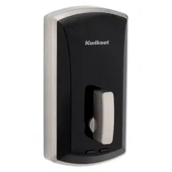
Interior Assembly
52241
52242
or
or
1-800-327-5625
52315-001
Rev 02
03809 (2x)
(For Latch/Strike Bag)
or
or
Square Corner
*Use longer screws if holes are worn out.
You will have two extra screws.
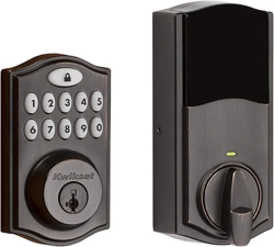
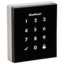
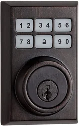
1000 SERIES DEADBOLT SMART LOCK
UP is on top.
UP is on top.
(For Latch/
Strike Bag
)
Note: Please contact customer service if door
thickness exceeds 1-3/4 in for a thick door kit.
C
Is the door edge chiselled with round or square corners?
Round Corner
A
B
Is the rectangular shaped hole centered in the door hole?
Hold the latch in front of the door hole, with the latch
face ush against the door edge.
No adjustment is required.
Proceed to next step.
Rectangular shaped hole
Rotate latch face as
shown to extend latch.
or
Square Corner
Remove round face with a
at head screwdriver and
use square face in
instruction 2-D.
YES NO
Rectangular shaped hole
or
53082
03809
Reinforcement
Plate
Batteries
reinforcement
plate
Proceed to next step.
52241
actual size
(2x)
For Lock
Bag
If latch does not extend or retract
smoothly, adjust screws. Use the
blade to test as shown.
a
b
d
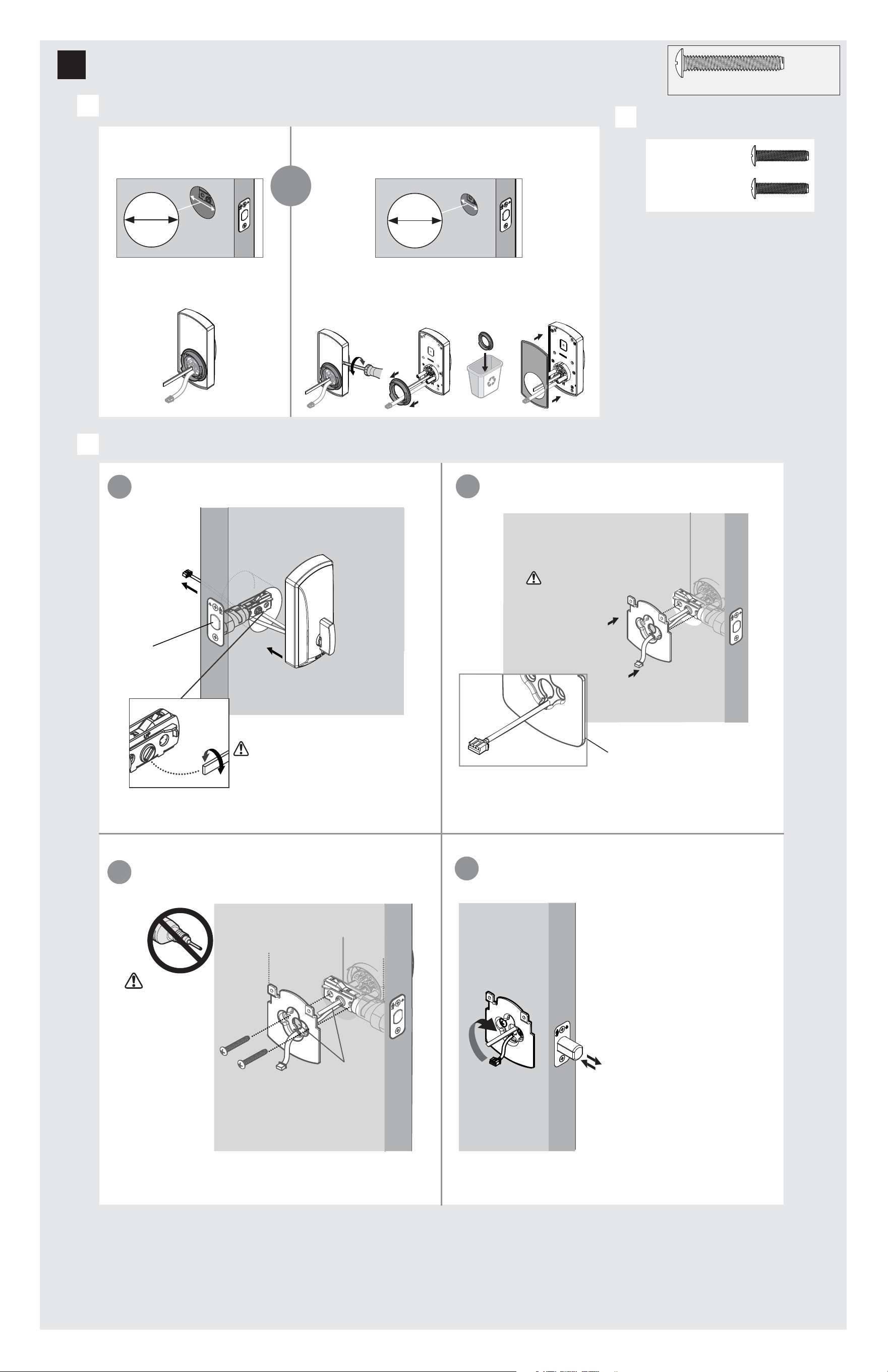
Make sure bolt
is RETRACTED
Cable goes
underneath latch.
Route cable through
center hole, then push
cable into bottom hole.
c
Tighten screws
evenly. DO NOT
over tighten screws.
mounting plate
installation.
Make sure the flat
blade is centered in the
mounting plate hole.
Keep mounting plate
parallel to edge of door.
52241
(2x)
(For Lock Bag)
What is the diameter of the hole in the door?
38 mm
1-1/2 in
Diameter is 2 -1/8 in
(54 mm)
Diameter is 1-1/2 in
(38 mm)
or
54 mm
2-1/8 in
Adapter ring is required for
installation.
assembly during
Support exterior
A
3
Install the exterior assembly
Install exterior assembly.
C
Locate screws for step 3C(c) and keep
them within reach.
B
52241
(2x)
(For Lock Bag)
Adapter ring is not needed for installation. Use a athead
screwdriver to loosen the rubber gasket. Once rubber gasket
is removed, take the adapter ring o, throw away, and place
the rubber gasket back on the interior assembly.
You may need to rotate the blade to match
the orientation of the slot on the latch.
Install exterior assembly. Route cable underneath the latch
bolt.
Install mounting plate.
2 / 4
3 / 4
Remove interior cover from interior assembly.
Install interior assembly onto mounting plate.
A
B
a
c
b
a
b
d
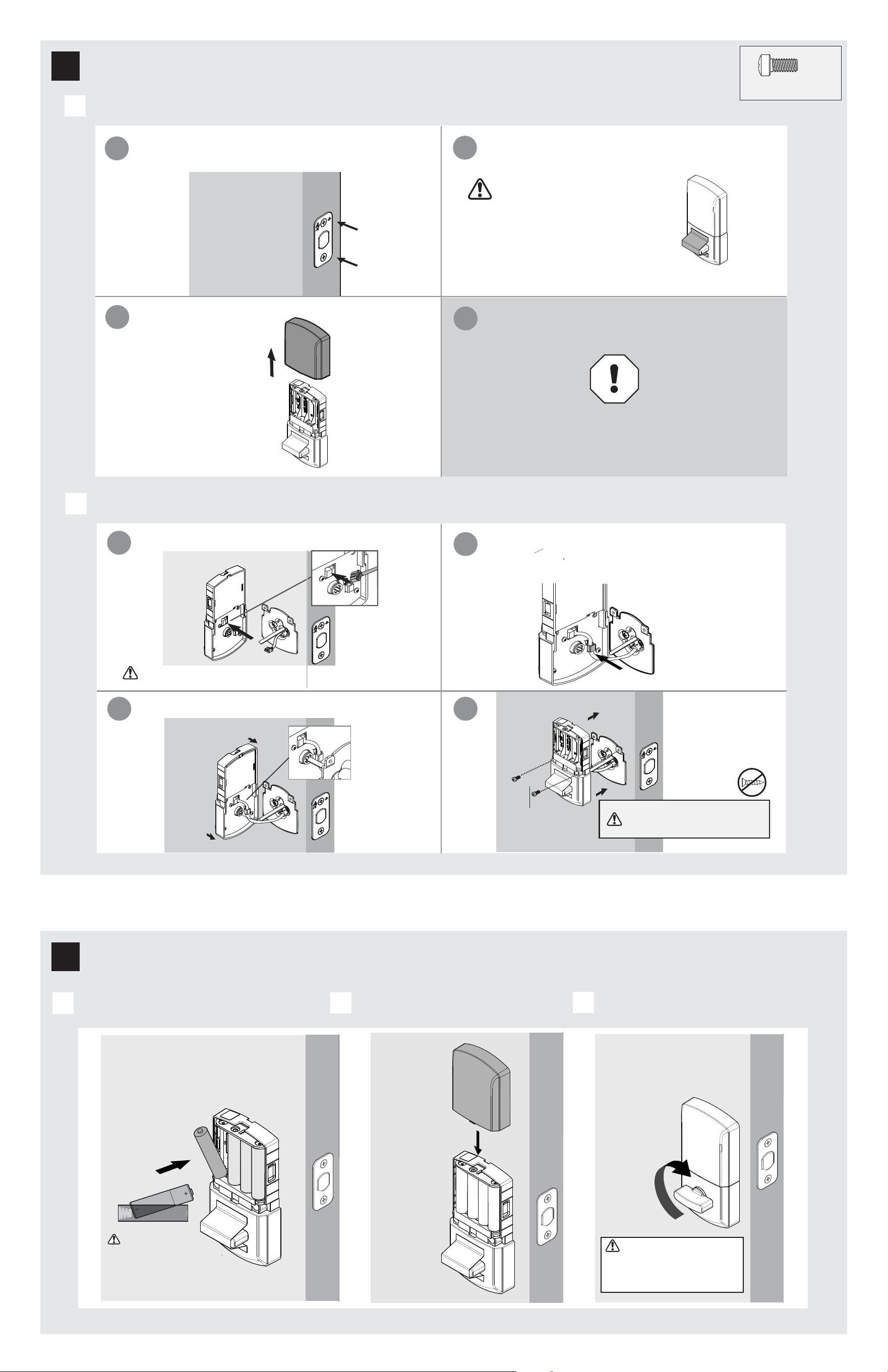
4
Install the interior assembly
52242
actual size
(2x)
For Lock
Bag
Remove the interior cover
from the interior assembly.
Ensure you are using the correct screws.
Using incorrect screws will damage
the product.
Check to make sure the latch bolt is in the retracted/
unlocked position to install the interior assembly.
If the turnpiece is not in a
horizontal position when the
bolt is retracted, locking and
unlocking could be reversed,
resulting in an unsecured
residence.
Do not install batteries
until step 5.
d
Route excess cable around the side notch
and bottom of the interior assembly.
c
Insert the flat blade into the turnpiece shaft.
Connect cable wire as shown. Ensure tight cable connection.
DO NOT REMOVE THE LABEL ON THE TURNPIECE
Install 4 AA batteries in interior assembly
A
B
Install interior cover for the interior assembly.
C
Test the lock.
5
Install the batteries in the interior assembly
Ensure the interior cover
is o to install batteries.
Remove the label from the
turnpiece to test the lock.
Extend and retract the bolt by
turning the internal turnpiece.
Once interior turnpiece is rotated
back to the horizontal position, the
exterior turnpiece will be enabled or
active for 5 seconds. Door MUST remain
open to avoid accidental lockout.
Ensure the red color on the connector is on the right side
and connects to the red color on the interior assembly.
52242
(2X)
(For Lock Bag)
Ensure the correct
polarity. For best results,
use new, non-chargeable
alkaline batteries only.
4 / 4
Reference Guide
© 2023 ASSA ABLOY
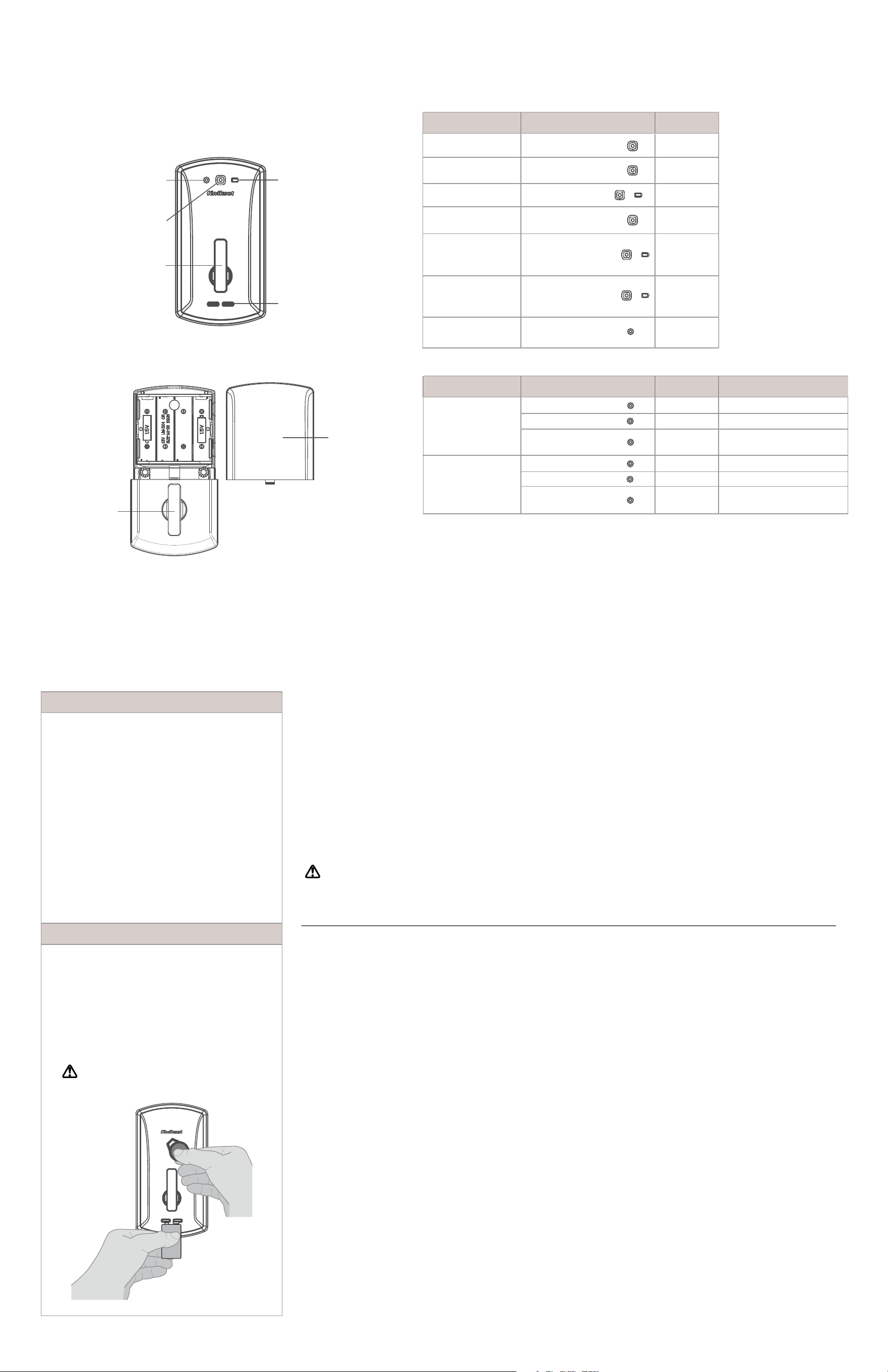
Exterior
Interior
Unite at a Glance
Lights BeepOperation
Flashes GREEN 5xAccess Granted
Solid GREEN 3s
Power on -
Full Battery Life
Status Solid GREEN
and battery LED light
AMBER 3s
Flashes RED 3xAccess Denied
Flashes RED 5xLow battery
Power on -
Low Battery Life
Lock identication
Enrollment
System Alerts
Power on -
Moderate Battery Life
Flashes BLUE
Solid GREEN 3s
Flashes RED 3x
BLE pairing start
Pairing complete
BLE pairing/
fail or timeout
Firmware Upgrade
Flashes BLUE
Solid GREEN 3s
Flashes RED 3x
Update start
Update complete
Update pairing/
fail or timeout
Turnpiece
9V terminals
Battery
LED light
Turnpiece
Battery
Cover
Important Safeguards
1. Read all instructions in their entirety.
2. Familiarize yourself with all warning and
caution statements.
3. Remind all family members of
safety precautions.
4. Always have access to your lock’s
credentials.
5.
6.
Familiarize yourself with all status LED lights
notifications.
7.
Replace low batteries immediately.
Dispose of used batteries according to local
laws and regulations.
WARNING: This Manufacturer advises that no lock can provide complete security by itself. This lock may be defeated by
forcible or technical means, or evaded by entry elsewhere on the property. No lock can substitute for caution, awareness of
your environment, and common sense. Builder’s hardware is available in multiple performance grades to suit the application. In
order to enhance security and reduce risk, you should consult a qualified locksmith or other security professional.
Solid BLUE 3s
Programming
LED light
Status
LED light
Programming your Lock
Lights ActionOperation
Status Solid GREEN
and battery LED light
RED 3s
Beep
1 Beep
3 Beeps
5 Beeps
1 Long Beep
1 Long Beep
1 Long Beep
then 5
Short Beeps
1 Long Beep
1 Long Beep
3 Beeps
1 Long Beep
3 Beeps
Manual Factory reset
1.
2.
3.
4.
Insert battery to power up the lock.
Status LED light displays GREEN 3s.
Rotate the interior turnpiece back and forth to extend
and retract bolt 3x within 5s.
Wait for programming LED light to alternate BLUE
and RED continuously.
Within 10s, rotate the interior turnpiece back and
forth 3x.
5.
6.
Program LED light will display solid GREEN for a
successful manual factory reset.
Fail/ Time out all LED lights will remain o.
Low Battery
If the 4 AA batteries are too low to operate the lock,
use a 9-Volt alkaline battery to temporarily power
the lock.
Make sure both terminals on the 9-Volt battery touch
the terminals below the turnpiece. Hold the 9-Volt in
place while holding the credential on the exterior of
the lock. Hold the 9-Volt battery as well as the
credential until the lock illuminates and unlocks.
WARNING: Change batteries immediately
otherwise the lock will remain unlocked.
-
-
Regulatory Compliance
FCC ID: NUL-UNT1
IC: 3022A-UNT1
This product complies with
standards established by the
following regulatory bodies:
Federal Communications
Commission (FCC)
• Industry Canada
FCC
This device's wireless operation
is safe and complies with RF
Exposure requirements. This
device complies with Part 15 of
the FCC Rules. Operation is
subject to the following two
conditions: ( 1 ) this device may
not cause harmful interference,
and ( 2 ) this device must accept
any interference received,
including interference that may
cause undesired operation. This
equipment has been tested and
found to comply with the limits
for a Class B digital device,
pursuant to Part 15 of the FCC
Rules. These limits are designed
to provide reasonable
protection against harmful
interference in a residential
installation. This equipment
generates, uses, and can radiate
radio frequency energy and, if
not installed and used in
accordance with the instructions,
may cause harmful interference
to radio communications.
However, there is no guarantee
that interference will not occur
in a particular installation. If this
equipment does cause harmful
interference to radio or television
reception, which can be
determined by turning the
equiptment o and on, the user
is encouraged to try to correct the
interference by one or more of the
following measures:
• Reorient or relocate the receiving
antenna.
• Increase the separation between
the equipment and receiver.
IMPORTANT! Changes or
modications not expressly
approved by the manufacturer
could void the user’s authority
to operate the equiptment.
Industry Canada
This device complies with
Industry Canada licence-
exempt RSS standard(s).
Operation is subject to the
following two conditions:
( 1 ) this device may not cause
interference, and ( 2 ) this device
must accept any interference,
including interference that may
cause undesired operation of the
device.
•
•
Connect the equiptment
into an outlet on a circuit
dierent from that to which
the receiver is connected.
• Consult the dealer or an
experienced radio/TV
technician for help.