
Network Speed Dome
Quick Start Guide

Network Speed Dome·Quick Start Guide
i
Quick Start Guide
© 2020 Hangzhou Hikvision Digital Technology Co., Ltd. All rights reserved.
This Manual is the property of Hangzhou Hikvision Digital Technology Co., Ltd. or its
affiliates (hereinafter referred to as “Hikvision”), and it cannot be reproduced, changed,
translated, or distributed, partially or wholly, by any means, without the prior written
permission of Hikvision. Unless otherwise expressly stated herein, Hikvision does not
make any warranties, guarantees or representations, express or implied, regarding to
the Manual, any information contained herein.
About this Manual
The Manual includes instructions for using and managing the Product. Pictures, charts,
images and all other information hereinafter are for description and explanation only.
The information contained in the Manual is subject to change, without notice, due to
firmware updates or other reasons. Please find the latest version of this Manual at the
Hikvision website (http://www.hikvision.com).
Please use this Manual with the guidance and assistance of professionals trained in
supporting the Product.
Trademarks Acknowledgement
and other Hikvision’s trademarks and logos are the properties of
Hikvision in various jurisdictions.
Other trademarks and logos mentioned are the properties of their respective
owners.
LEGAL DISCLAIMER
TO THE MAXIMUM EXTENT PERMITTED BY APPLICABLE LAW, THIS MANUAL AND THE
PRODUCT DESCRIBED, WITH ITS HARDWARE, SOFTWARE AND FIRMWARE, ARE
PROVIDED “AS IS” AND “WITH ALL FAULTS AND ERRORS”. HIKVISION MAKES NO
WARRANTIES, EXPRESS OR IMPLIED, INCLUDING WITHOUT LIMITATION,
MERCHANTABILITY, SATISFACTORY QUALITY, OR FITNESS FOR A PARTICULAR PURPOSE.
THE USE OF THE PRODUCT BY YOU IS AT YOUR OWN RISK. IN NO EVENT WILL HIKVISION
BE LIABLE TO YOU FOR ANY SPECIAL, CONSEQUENTIAL, INCIDENTAL, OR INDIRECT
DAMAGES, INCLUDING, AMONG OTHERS, DAMAGES FOR LOSS OF BUSINESS PROFITS,
BUSINESS INTERRUPTION, OR LOSS OF DATA, CORRUPTION OF SYSTEMS, OR LOSS OF
DOCUMENTATION, WHETHER BASED ON BREACH OF CONTRACT, TORT (INCLUDING
NEGLIGENCE), PRODUCT LIABILITY, OR OTHERWISE, IN CONNECTION WITH THE USE OF
THE PRODUCT, EVEN IF HIKVISION HAS BEEN ADVISED OF THE POSSIBILITY OF SUCH
DAMAGES OR LOSS.
YOU ACKNOWLEDGE THAT THE NATURE OF INTERNET PROVIDES FOR INHERENT
SECURITY RISKS, AND HIKVISION SHALL NOT TAKE ANY RESPONSIBILITIES FOR

Network Speed Dome·Quick Start Guide
ii
ABNORMAL OPERATION, PRIVACY LEAKAGE OR OTHER DAMAGES RESULTING FROM
CYBER-ATTACK, HACKER ATTACK, VIRUS INSPECTION, OR OTHER INTERNET SECURITY
RISKS; HOWEVER, HIKVISION WILL PROVIDE TIMELY TECHNICAL SUPPORT IF REQUIRED.
YOU AGREE TO USE THIS PRODUCT IN COMPLIANCE WITH ALL APPLICABLE LAWS, AND
YOU ARE SOLELY RESPONSIBLE FOR ENSURING THAT YOUR USE CONFORMS TO THE
APPLICABLE LAW. ESPECIALLY, YOU ARE RESPONSIBLE, FOR USING THIS PRODUCT IN A
MANNER THAT DOES NOT INFRINGE ON THE RIGHTS OF THIRD PARTIES, INCLUDING
WITHOUT LIMITATION, RIGHTS OF PUBLICITY, INTELLECTUAL PROPERTY RIGHTS, OR
DATA PROTECTION AND OTHER PRIVACY RIGHTS. YOU SHALL NOT USE THIS PRODUCT
FOR ANY PROHIBITED END-USES, INCLUDING THE DEVELOPMENT OR PRODUCTION OF
WEAPONS OF MASS DESTRUCTION, THE DEVELOPMENT OR PRODUCTION OF CHEMICAL
OR BIOLOGICAL WEAPONS, ANY ACTIVITIES IN THE CONTEXT RELATED TO ANY NUCLEAR
EXPLOSIVE OR UNSAFE NUCLEAR FUEL-CYCLE, OR IN SUPPORT OF HUMAN RIGHTS
ABUSES.
IN THE EVENT OF ANY CONFLICTS BETWEEN THIS MANUAL AND THE APPLICABLE LAW,
THE LATER PREVAILS.
05060020200511

Network Speed Dome·Quick Start Guide
iii
Regulatory Information
FCC Information
Please take attention that changes or modification not expressly approved by the party
responsible for compliance could void the user’s authority to operate the equipment.
FCC compliance: This equipment has been tested and found to comply with the limits
for a Class A digital device, pursuant to part 15 of the FCC Rules. These limits are
designed to provide reasonable protection against harmful interference when the
equipment is operated in a commercial environment. This equipment generates, uses,
and can radiate radio frequency energy and, if not installed and used in accordance with
the instruction manual, may cause harmful interference to radio communications.
Operation of this equipment in a residential area is likely to cause harmful interference
in which case the user will be required to correct the interference at his own expense.
FCC Conditions
This device complies with part 15 of the FCC Rules. Operation is subject to the following
two conditions:
1. This device may not cause harmful interference.
2. This device must accept any interference received, including interference that may
cause undesired operation
EU Conformity Statement
This product and - if applicable - the supplied accessories too are marked
with "CE" and comply therefore with the applicable harmonized European
standards listed under the EMC Directive 2014/30/EU, the RoHS Directive
2011/65/EU.
2012/19/EU (WEEE directive): Products marked with this symbol cannot be
disposed of as unsorted municipal waste in the European Union. For proper
recycling, return this product to your local supplier upon the purchase of
equivalent new equipment, or dispose of it at designated collection points.
For more information see: www.recyclethis.info.
2006/66/EC (battery directive): This product contains a battery that cannot
be disposed of as unsorted municipal waste in the European Union. See the
product documentation for specific battery information. The battery is
marked with this symbol, which may include lettering to indicate cadmium
(Cd), lead (Pb), or mercury (Hg). For proper recycling, return the battery to your supplier
or to a designated collection point. For more information see: www.recyclethis.info.
Industry Canada ICES-003 Compliance
This device meets the CAN ICES-3 (A)/NMB-3(A) standards requirements.
Network Speed Dome·Quick Start Guide
iv
Safety Instruction
These instructions are intended to ensure that user can use the product correctly to
avoid danger or property loss.
The precaution measure is divided into Warnings and Cautions:
Warnings: Neglecting any of the warnings may cause serious injury or death.
Cautions: Neglecting any of the cautions may cause injury or equipment damage.
Warnings
In the use of the product, you must be in strict compliance with the electrical safety
regulations of the nation and region.
Refer to technical specifications for detailed information.
Input voltage should meet both the SELV (Safety Extra Low Voltage) and the Limited
Power Source with 24 VAC or 12 VDC according to the IEC60950-1 standard. Refer to
technical specifications for detailed information.
Do not connect several devices to one power adapter as adapter overload may cause
over-heating or a fire hazard.
Make sure that the plug is firmly connected to the power socket.
Make sure that the power has been disconnected before you wire, install or dismantle
the speed dome.
When the product is mounted on wall or ceiling, the device shall be firmly fixed.
If smoke, odor or noise rise from the device, turn off the power at once and unplug
the power cable, and then contact the service center.
If the product does not work properly, contact your dealer or the nearest service
center. Never attempt to disassemble the speed dome yourself. (We shall not assume
any responsibility for problems caused by unauthorized repair or maintenance.)
Cautions
CAUTION: Hot parts! Burned fingers when handling the parts. Wait one-half hour
after switching off before handling parts. This sticker is to
indicate that the marked item can be hot and should not be
touched without taking care. For device with this sticker, this
Warnings Follow
these safeguards to
prevent serious
injury or death.
Cautions Follow these
precautions to prevent
potential injury or
material damage.

Network Speed Dome·Quick Start Guide
v
device is intended for installation in a restricted access location, access can only be
gained by service persons or by users who have been instructed about the reasons for
the restrictions applied to the location and about any precautions that shall be taken.
If the speed dome fails to synchronize local time with that of the network, you need
to set up speed dome time manually. Visit the speed dome (via web browser or client
software) and enter system settings interface for time settings.
Make sure the power supply voltage is correct before using the speed dome.
Do not drop the speed dome or subject it to physical shock, and do not expose it to
high electromagnetism radiation. Avoid installation on vibrations surface or places
subject to shock (ignorance can cause device damage).
Do not touch senor modules with fingers. If cleaning is necessary, use clean cloth with
a bit of ethanol and wipe it gently. If the speed dome will not be used for an extended
period, replace the lens cap to protect the sensor from dirt.
Do not aim the speed dome at the sun or extra bright places. Blooming or smearing
may occur otherwise (which is not a malfunction), and affect the endurance of sensor
at the same time.
The sensor may be burned out by a laser beam, so when any laser equipment is in
using, make sure that the surface of sensor will not be exposed to the laser beam.
Do not place the speed dome in extremely hot, cold, dusty or damp locations, and do
not expose it to high electromagnetic radiation.
To avoid heat accumulation, good ventilation is required for operating environment.
Keep the speed dome away from liquid while in use.
While in delivery, the speed dome shall be packed in its original packing, or packing of
the same texture.
Improper use or replacement of the battery may result in hazard of explosion.
Replace with the same or equivalent type only. Dispose of used batteries according to
the instructions provided by the battery manufacturer.
L’utilisation ou le remplacement inadéquats de la pile peuvent entraîner un risque
d’explosion. Remplacez-la par le même type ou l’équivalent du même type seulement.
Jetez les piles usagées conformément aux directives fournies par le fabricant de la
pile.

Network Speed Dome·Quick Start Guide
vi
Table of Contents
1 Overview ...................................................................................................... 1
1.1 Speed Dome Overview ............................................................................................ 1
1.1.1 Overview of Type I Speed Dome ....................................................................... 1
1.1.2 Overview of Type II Speed Dome ...................................................................... 1
1.1.3 Overview of Type III Speed Dome ..................................................................... 2
1.1.4 Overview of Type IV Speed Dome ..................................................................... 3
1.1.5 Overview of Type V Speed Dome ...................................................................... 3
1.1.6 Overview of Type VI Speed Dome ..................................................................... 4
1.1.7 Overview of Type VII Speed Dome .................................................................... 4
1.1.8 Overview of Type VIII Speed Dome ................................................................... 5
1.1.9 Overview of Type IX Speed Dome ..................................................................... 5
1.2 Cable Interfaces ....................................................................................................... 5
1.3 Alarm Output ........................................................................................................... 6
2 Installation ................................................................................................... 7
2.1 Installing Type I Speed Dome ................................................................................... 7
2.1.1 Wall Mounting................................................................................................... 7
2.1.2 In-ceiling Mounting ......................................................................................... 11
2.1.3 Ceiling Mounting ............................................................................................. 13
2.2 Installing Type II Speed Dome ................................................................................ 16
Wall Mounting ......................................................................................................... 16
2.3 Installing Type III Speed Dome ............................................................................... 19
Wall Mounting ......................................................................................................... 19
2.4 Installing Type IV Speed Dome .............................................................................. 22
Wall Mounting ......................................................................................................... 22
2.5 Installing Type V Speed Dome ............................................................................... 26
Wall Mounting ......................................................................................................... 26
2.6 Installing Type VI and VII Speed Dome .................................................................. 29
Wall Mounting ......................................................................................................... 29
Pendant Mounting ................................................................................................... 32
2.7 Installing Type VIII Speed Dome ............................................................................ 34
Wall Mounting ......................................................................................................... 34
Horizontal Pole Mounting ........................................................................................ 36
Vertical Pole Mounting ............................................................................................. 38
Pendant Mounting ................................................................................................... 40
2.8 Installing Type IX Speed Dome ............................................................................... 42
Wall Mounting ......................................................................................................... 42
Pendant Mounting ................................................................................................... 43
2.9 Installation of Network Cable Waterproof Jacket .................................................. 43
2.10 Installation of Water-proof Tape .......................................................................... 44
2.11 Protective Measures for Outdoor Installation ..................................................... 46
3 Activate and Access Network Camera......................................................... 47
Network Speed Dome·Quick Start Guide
1
1 Overview
1.1 Speed Dome Overview
The network speed dome has EIGHT types. The figures below are for reference only,
refer to the actual product as the standard.
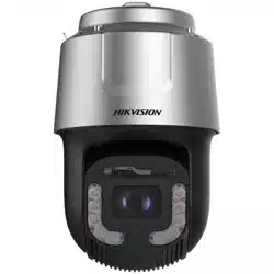
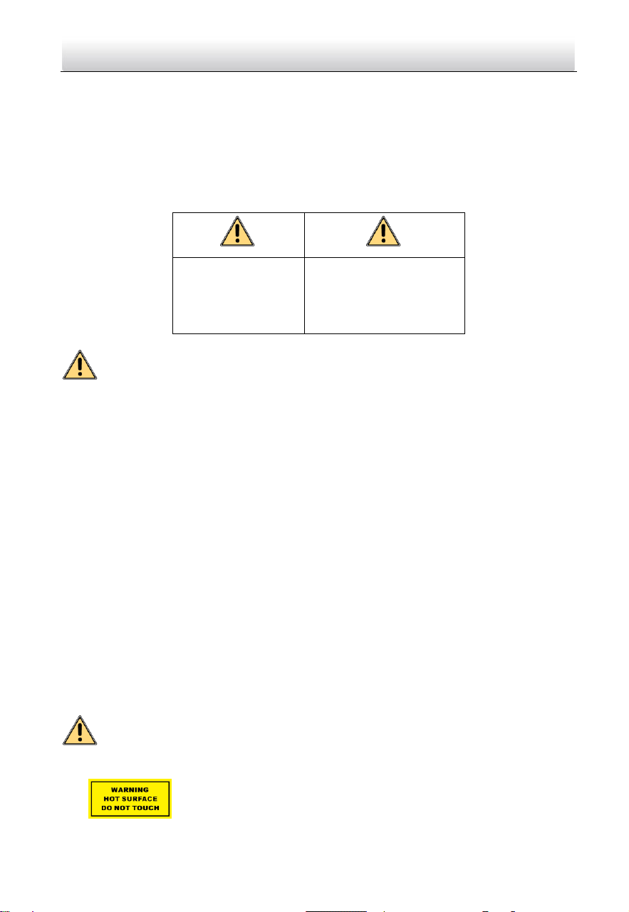
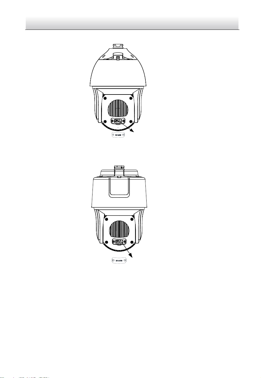
1.1.1 Overview of Type I Speed Dome
Figure 1-1 Overview of Type I Speed Dome
Memory Card Slot
Figure 1-2 Memory Card Slot
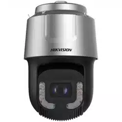
1.1.2 Overview of Type II Speed Dome
Note:
There are two different appearances of Type II speed dome. Refer to the actual product
for the location of memory card slot.
Network Speed Dome·Quick Start Guide
2
Figure 1-3 Overview of Type II Speed Dome
Memory Card Slot
Debug
Reset
Memory Card Slot
Figure 1-4 Memory Card Slot
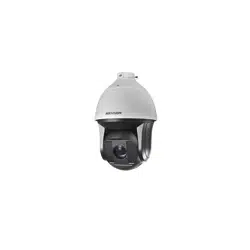
1.1.3 Overview of Type III Speed Dome
SD
CARD
Memory Card Slot
Figure 1-5 Overview of Type III Speed Dome
Network Speed Dome·Quick Start Guide
3
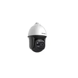
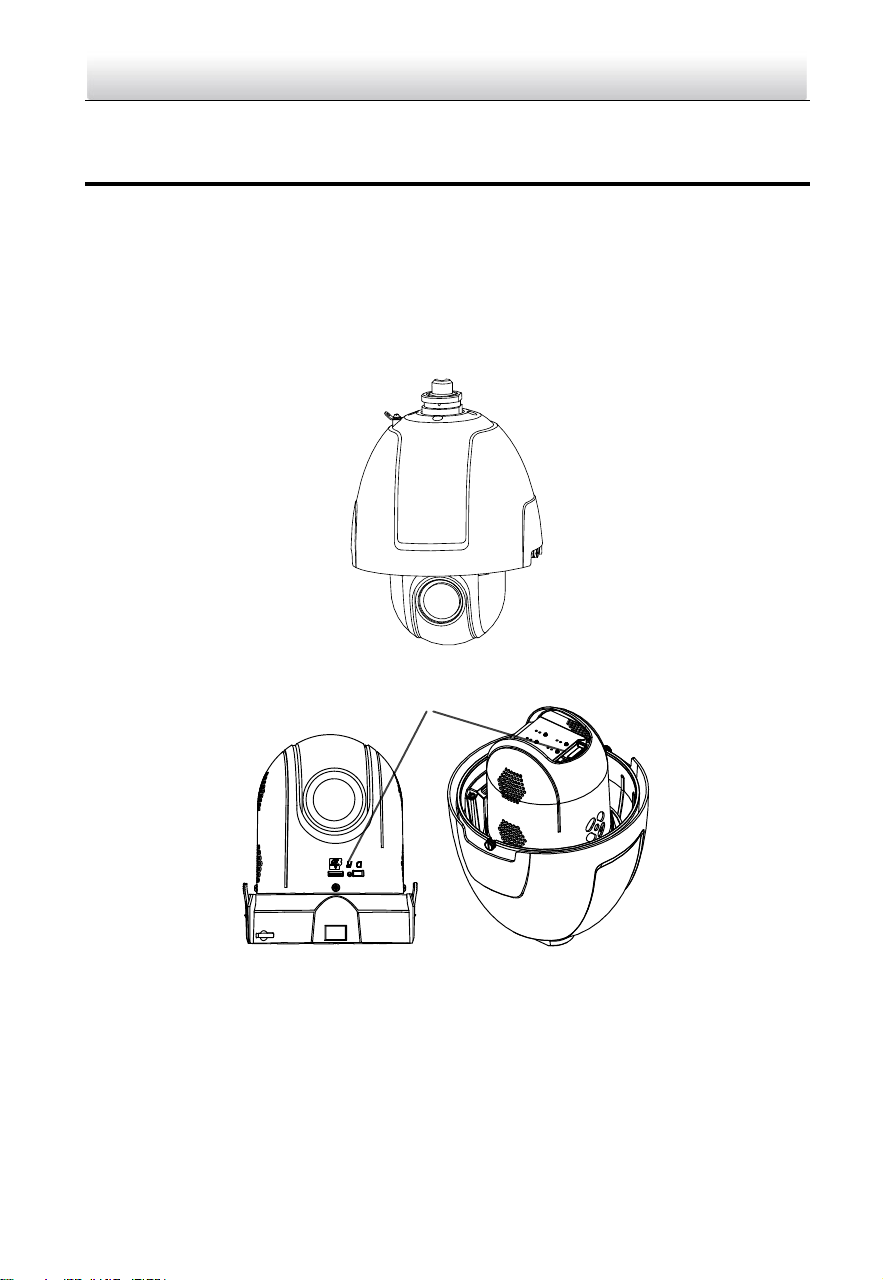
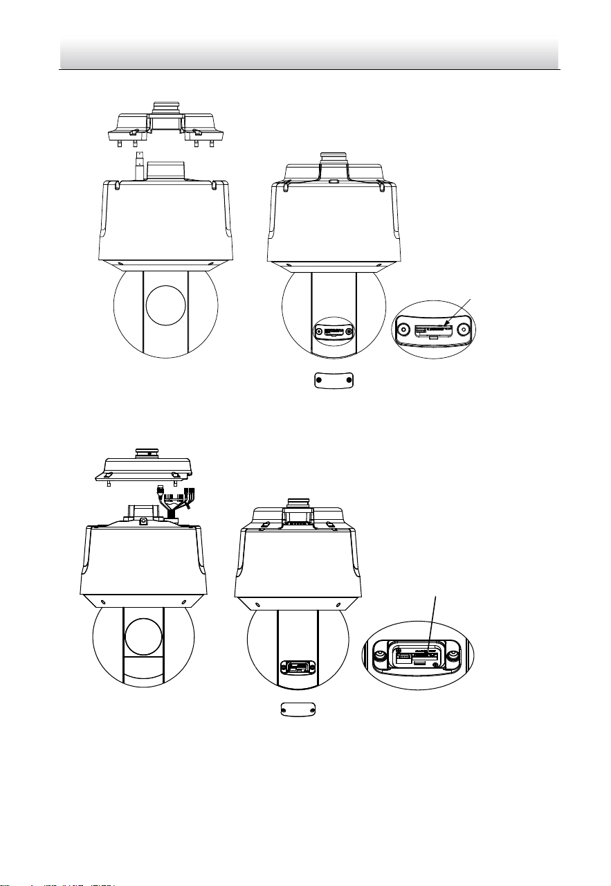
1.1.4 Overview of Type IV Speed Dome
Memory Card Slot
Figure 1-6 Overview of Type IV Speed Dome
1.1.5 Overview of Type V Speed Dome
Memory Card Slot
Figure 1-7 Overview of Type V Speed Dome
Network Speed Dome·Quick Start Guide
4
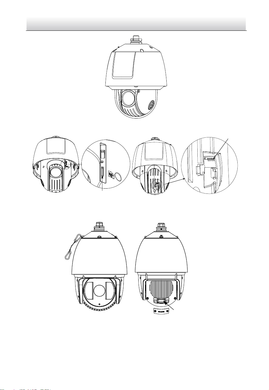
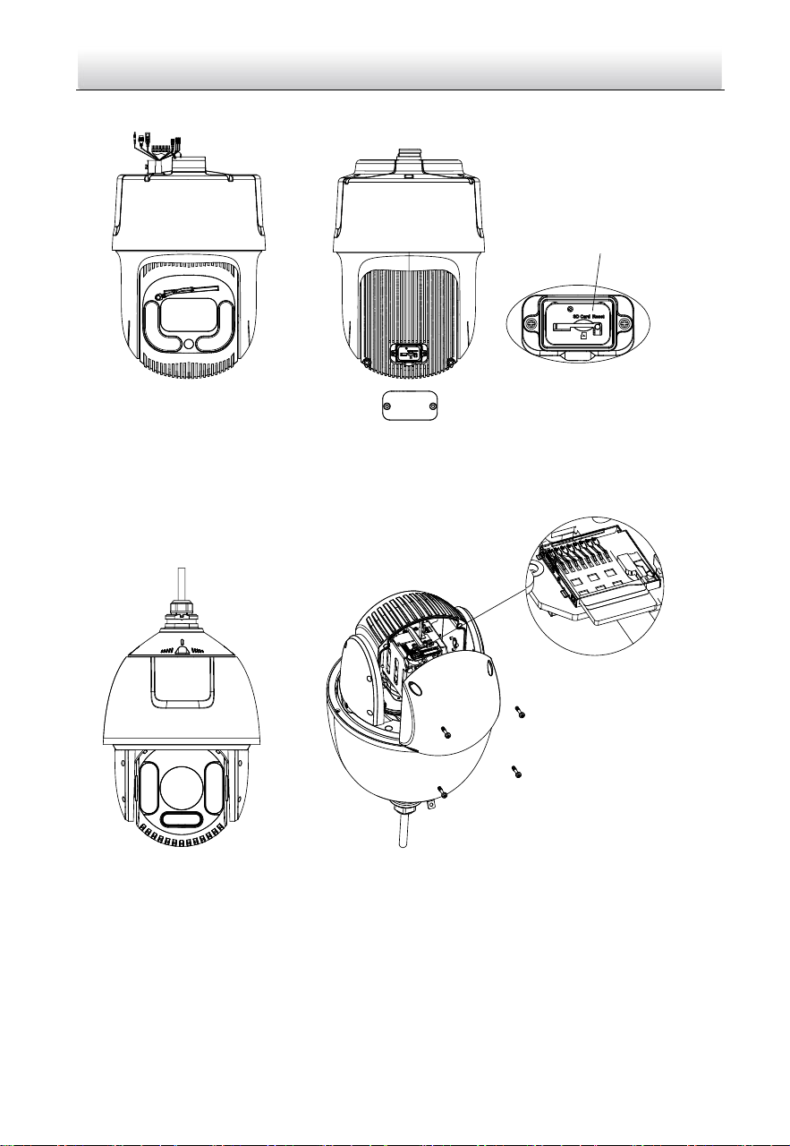
1.1.6 Overview of Type VI Speed Dome
Memory Card Slot
and Reset Button
Figure 1-8 Overview of Type VI Speed Dome
1.1.7 Overview of Type VII Speed Dome
Memory Card Slot and Reset
Button
Figure 1-9 Overview of Type VII Speed Dome
Network Speed Dome·Quick Start Guide
5
1.1.8 Overview of Type VIII Speed Dome
线
线
Memory Card Slot and Reset
Button
Figure 1-10 Overview of Type VIII Speed Dome
1.1.9 Overview of Type IX Speed Dome
Memory Card Slot
Figure 1-11 Overview of Type IX Speed Dome
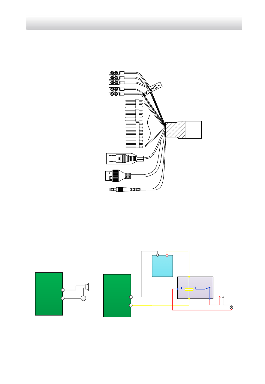
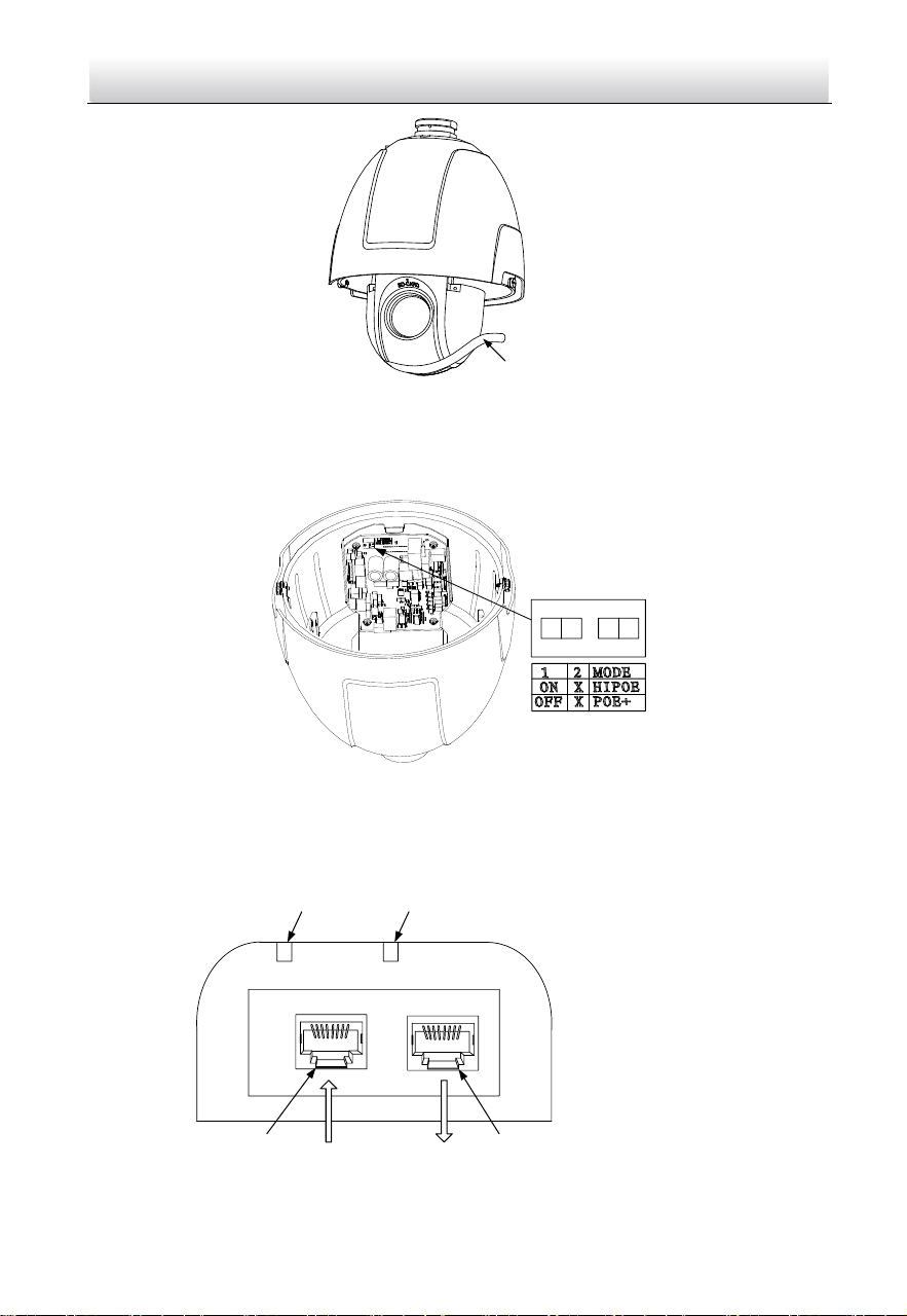
1.2 Cable Interfaces
The cable interfaces of the speed dome are shown below. The cables are distinguished
by different colors. Refer to the labels attached on the cables for identification.
Notes:
The cables vary depending on different speed dome models.
Network Speed Dome·Quick Start Guide
6
Make sure the speed dome is power-off before you connect the cables.
Water-proof treatment is required for cable connectors. Refer to Section 2.9 and
2.10 for details.
Network Cable
Audio Cable
Alarm Cable
Video Cable
RS-485 Cable
Power Cord
Optical Fiber
Figure 1-12 Cable Interfaces
1.3 Alarm Output
Alarm output is shown below.
Relay Output
OUT (n)
DC
OUT (n)
Direct load
+
-
Relay Output
OUT (n)
OUT (n)
DC 30V
1A
Power Supply
GND Output
~220V AC
FireWire
Zero
Line
JQC-3FG
Relay
(10A 250VAC)
Figure 1-13 Alarm Output

Network Speed Dome·Quick Start Guide
7
2 Installation
Before you start:
Check the package contents and make sure that the device in the package is in good
condition and all the assembly parts are included.
Notes:
Do not touch the bubble directly by hand. The image blurs otherwise.
Do not power the speed dome up until the installation is finished. To ensure the
safety of personnel and equipment, all the installation steps should be done with
power supply off.
Do not drag the speed dome with its waterproof cables; otherwise the waterproof
performance is affected.
Figure 2-1 Do Not Drag the Cables
2.1 Installing Type I Speed Dome
2.1.1 Wall Mounting
Notes:
For cement wall, you need to use the expansion screw to fix the bracket. The
mounting hole of the expansion pipe on the wall should align with the mounting
hole on the bracket.
For wooden wall, you can just use the self-tapping screw to fix the bracket.
Make sure that the wall is strong enough to withstand more than eight times the
weight of the speed dome and the accessories.
The bracket in Figure 2-7 is the recommended bracket for this series of speed dome,
and a pendent adapter is required if any other bracket is selected. The dimension of
pendant adapter is G1
1
2
.
Network Speed Dome·Quick Start Guide
8
Water-proof treatment is required for cable connectors. Refer to Section 2.9 and
2.10 for details.
Steps:
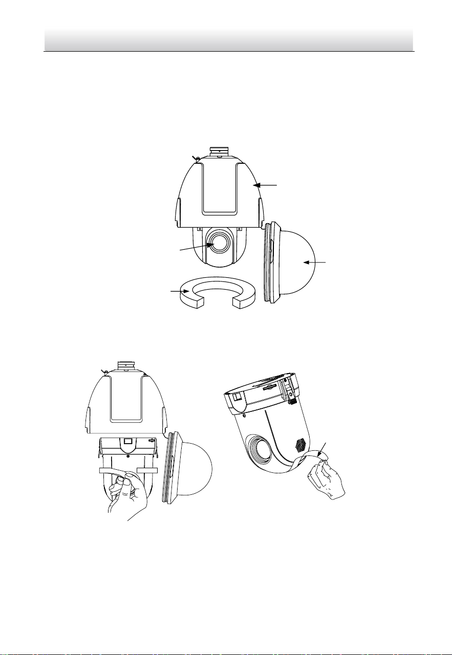
1. Loosen the two lock screws on both sides of the speed dome.
Note:
Do not remove the lock screws from the speed dome.
Back Box
Bubble
Protective Foam
Lens Cover
Figure 2-2 Remove the Bubble
2. Pull the bubble to separate it from the back box, and remove the protective
accessories.
Protective Sticker
Figure 2-3 Remove the Protective Accessories for Separated Speed Dome
Network Speed Dome·Quick Start Guide
9
Protective Sticker
Figure 2-4 Remove the Protective Accessories for Integrated Speed Some
3. If the speed dome supports PoE (Power over Ethernet) function, you can switch the
PoE+ and Hi-PoE function for the speed dome. If PoE function is not supported, skip
this step.
1
2
ON
Figure 2-5 PoE+ and Hi-PoE Switch
Note:
If you choose Hi-PoE, a Hi-PoE adapter must be connected. The Hi-PoE module
connection is shown in Figure 2-6.
1
2
3 4
Network Speed Dome
Ethernet
1: Power Indicator
2: PORT Indicator
3: DATA & POWER OUT
4: DATA IN
Figure 2-6 Hi-PoE Connection
Network Speed Dome·Quick Start Guide
10
Connecting Hi-PoE
Steps:
1) Connect the Hi-PoE module to the Internet via the DATA IN interface with a
network cable.
2) Connect the Hi-PoE module to the speed dome via the DATA & POWER OUT
interface with a network cable.
3) Power on the Hi-PoE module.
4. Install the memory card.
5. Align the cuts on the bubble with the lock screws on the back box to reinstall the
bubble. Tighten the lock screws.
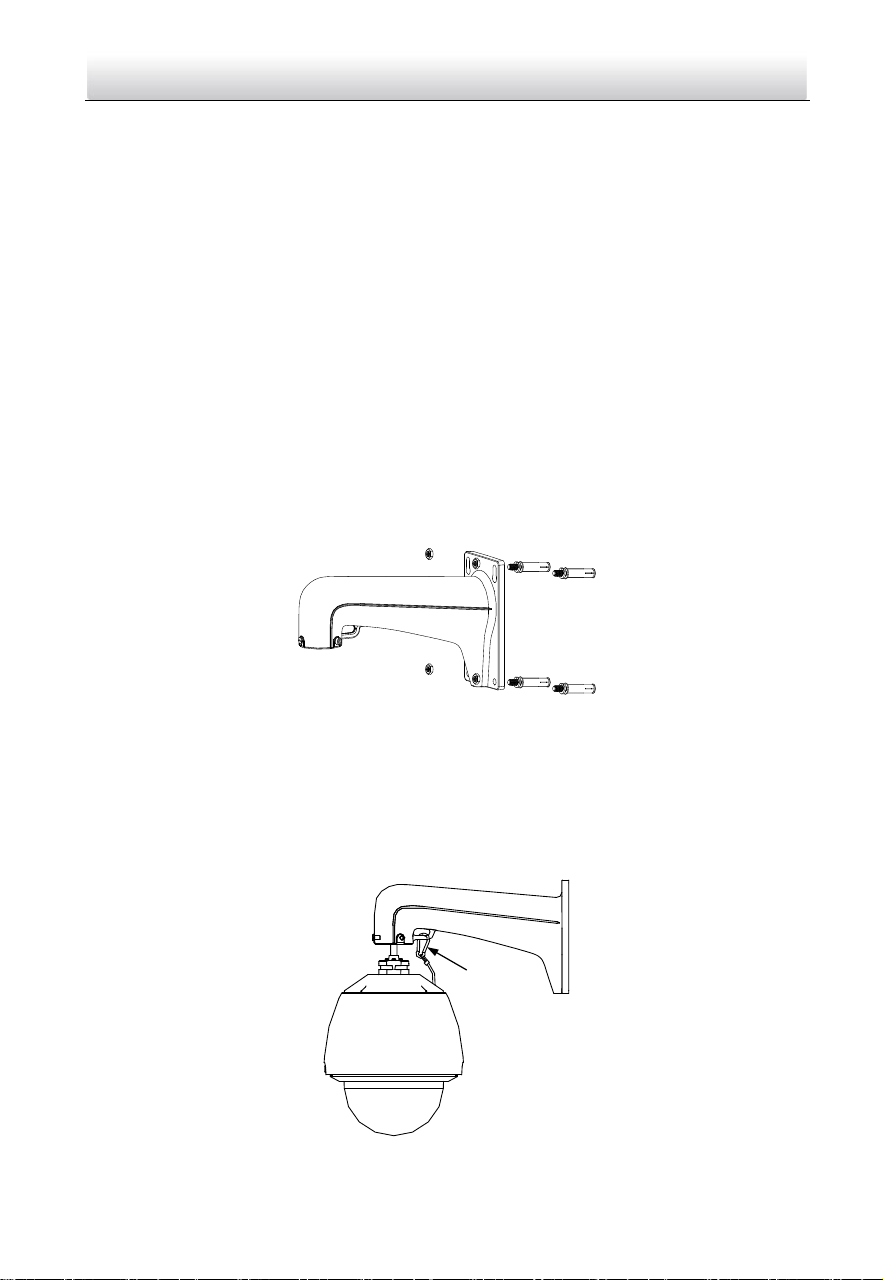
6. Install the bracket.
1). Drill four screw holes in the wall according to the holes on the bracket, and then
insert four M8 expansion screws into the mounting holes.
2). Attach the gasket and the bracket to the wall by aligning the four screw holes on
the bracket with four expansion screws on the wall.
3). Secure the bracket with four hex nuts and washers.
Figure 2-7 Secure the Bracket
7. Install the speed dome to the bracket.
1). Hang the safety rope to the speed dome and the hook on the bracket as shown
in Figure 2-8.
2). Route the speed dome cables through the bracket.
3). Connect the corresponding cables.
Safety Rope
Figure 2-8 Hang the Safety Rope
Network Speed Dome·Quick Start Guide
11
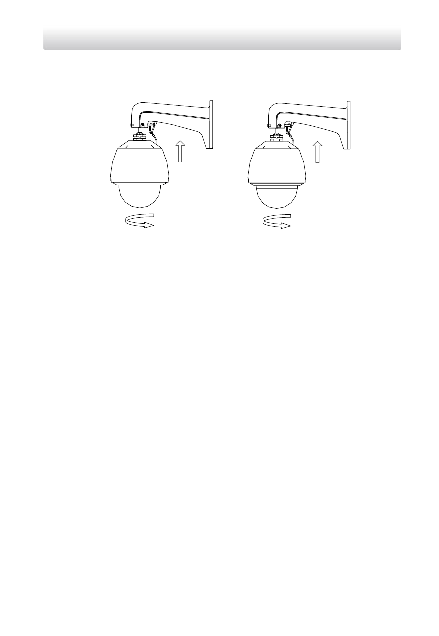
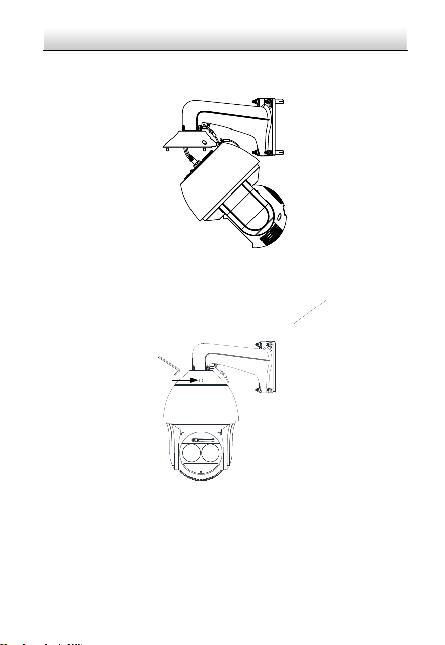
4). Loosen the two lock screws on the bracket.
5). Install the speed dome to the bracket. Rotate the speed dome clockwise tightly.
6). Secure the two lock screws with the wrench.
Lock Screw
Lock Screw
Figure 2-9 Install the Speed Dome to the Bracket
8. Remove the protective film on the bubble after the installation is finished.
2.1.2 In-ceiling Mounting
Note:
In-ceiling mounting is only supported by indoor speed dome models of Type I.
Before you start:
The height of the space above the ceiling must be more than 250 mm.
The thickness of the ceiling must range from 5 mm to 40 mm.
The ceiling must be strong enough to withstand more than four times the weight of
the speed dome and the accessories.
Water-proof treatment is required for cable connectors. Refer to Section 2.9 and
2.10 for details.
Steps:
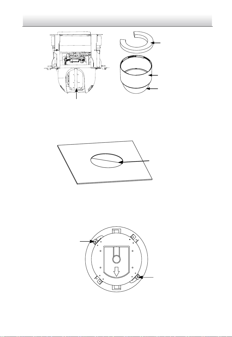
1. Rotate the bubble counterclockwise to separate it from the back box.
2. Remove the protective lens cover, foam, and sticker from the dome drive.
3. Install the memory card.
4. Attach the bubble to the back box, and rotate clockwise to secure it.
Network Speed Dome·Quick Start Guide
12
Protective Sticker
Protective Foam
Back Box
Bubble
Figure 2-10 Remove the Protective Accessories
5. Drill a hole on the ceiling according to the drill template (supplied).
Note:
±2 mm of the circle diameter is tolerable.
Φ 224
Unit: mm
Figure 2-11 Drill a Hole on the Ceiling
6. Connect the cables.
7. Install the speed dome to the ceiling.
1). Loosen the two lock screws on both sides of the back box and make the locks in
internal position as shown in Figure 2-12.
Lock
Lock
Figure 2-12 Locks and Lock Screws
Network Speed Dome·Quick Start Guide
13
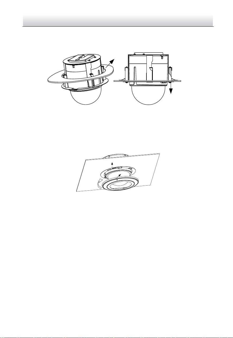
2). Push the speed dome into the mounting hole in the ceiling.
3). Tighten the lock screws with the screwdriver and the locks will automatically
rotate outwards to secure the in-ceiling bracket to the ceiling.
Lock
Ceiling
Figure 2-13 Install the Back Box
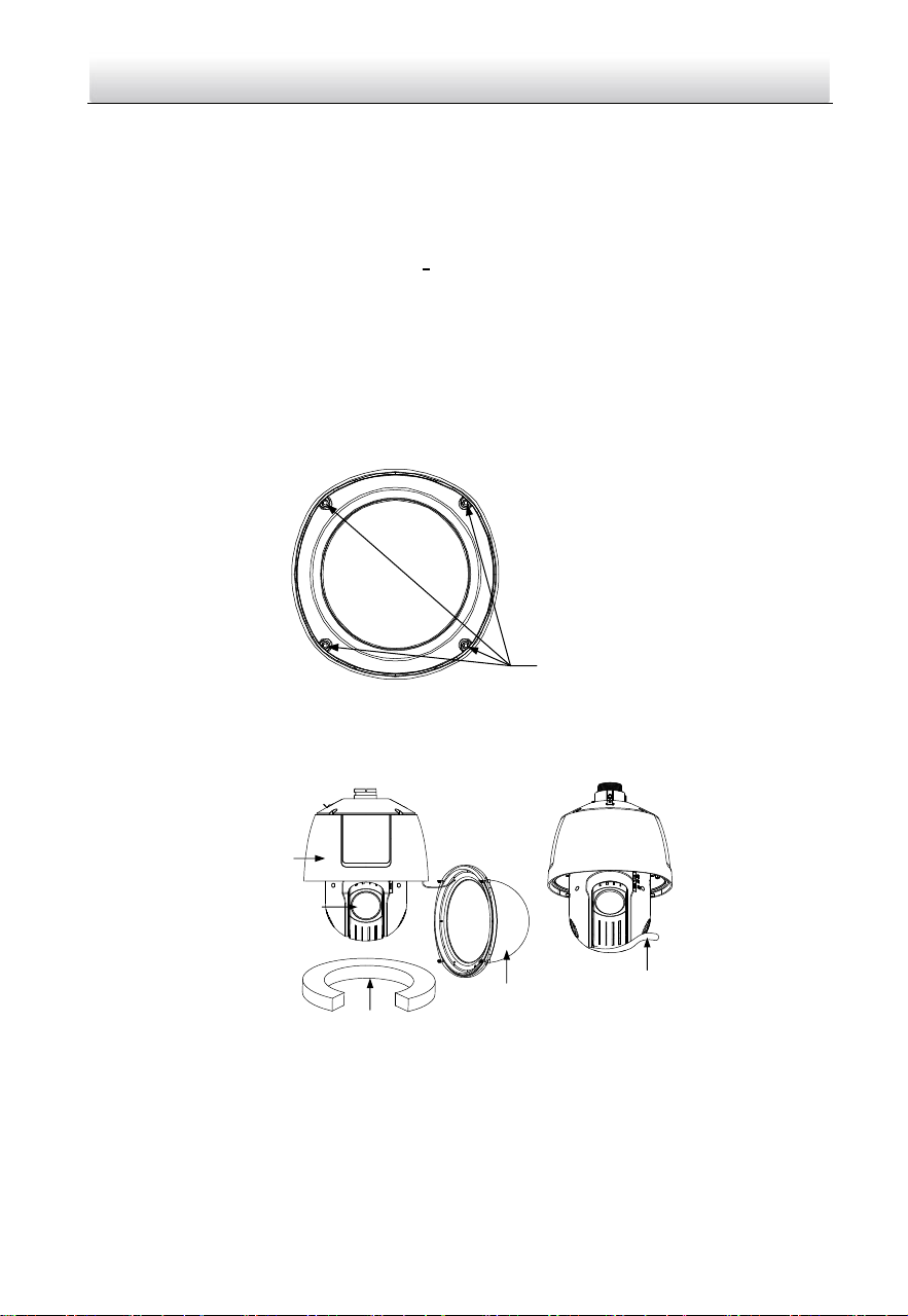
8. Install the flange.
1). Attach the flange to the bubble and align the triangular notch of the trim ring
with the arrow label on the in-ceiling bracket.
2). Firmly place the flange to the ceiling, and rotate the flange in the direction of the
arrow to secure it.
Notch
Arrow Label
Figure 2-14 Install the Flange
9. Remove the protective film on the bubble after the installation is finished.
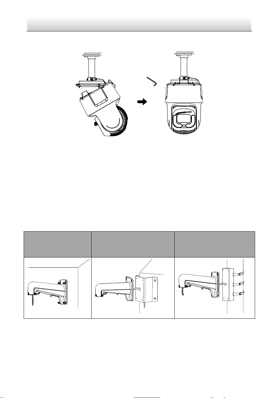
2.1.3 Ceiling Mounting
Note:
Ceiling mounting is only supported by indoor speed dome models of Type I.
Before you start:
The thickness of the ceiling must range from 5 mm to 40 mm.
The ceiling must be strong enough to withstand more than four times the weight of
the speed dome and the accessories.
If the speed dome is installed to the wooden ceiling, use the self-tapping screws to
secure the mounting base.
If the speed dome is installed to the cement ceiling, drill three Φ5 mm screw holes
onto the ceiling according to the position of the holes, and then secure the
mounting base to the ceiling with expansion screws.
Network Speed Dome·Quick Start Guide
14
Water-proof treatment is required for cable connectors. Refer to Section 2.9 and
2.10 for details.
Steps:
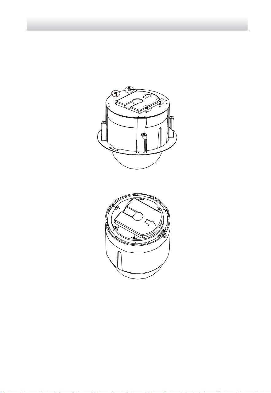
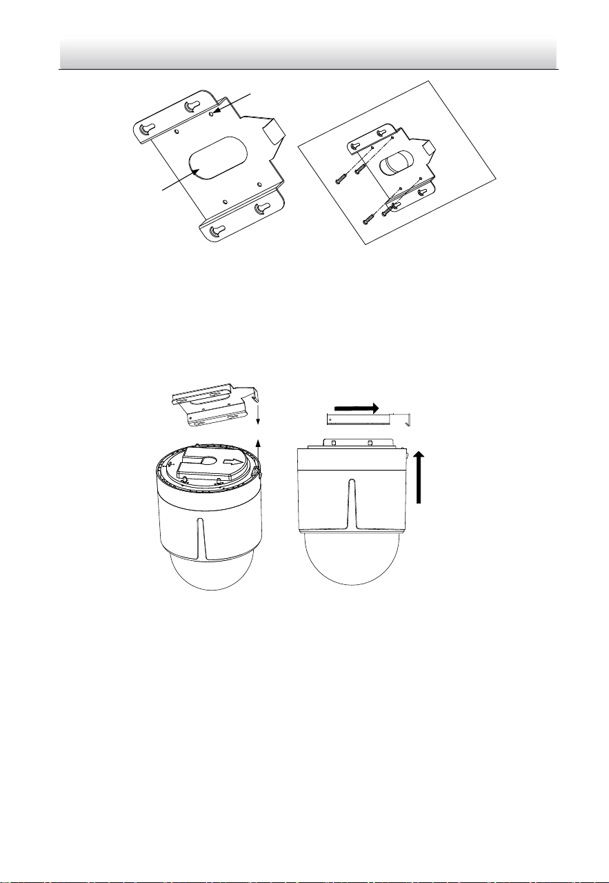
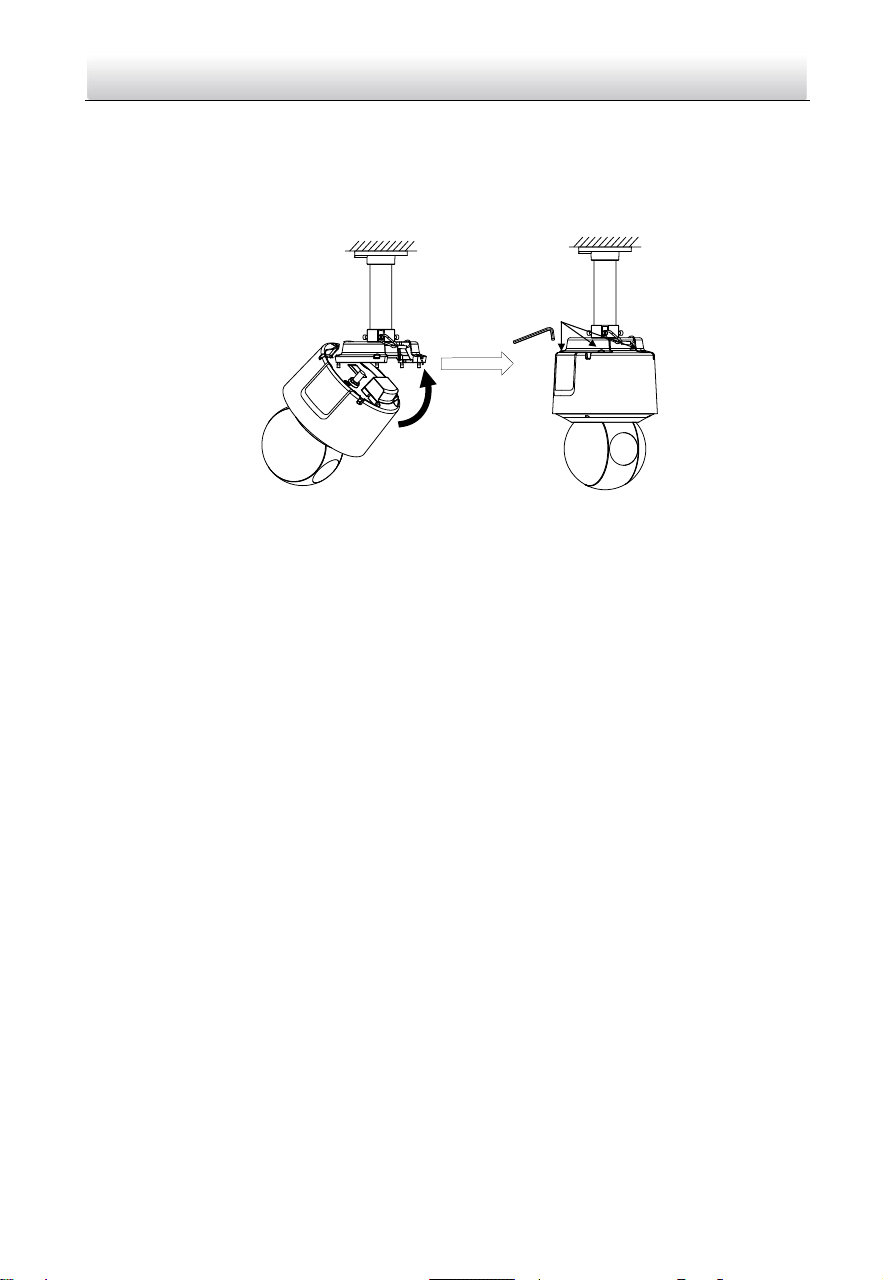
1. The ceiling mounting speed dome is installed with an in-ceiling bracket by default.
You need to remove the in-ceiling bracket first before you install the speed dome.
1). Loosen and remove the four screws as shown in Figure 2-15.
Figure 2-15 Remove the Screws
2). Remove the in-ceiling bracket as shown in Figure 2-16.
Figure 2-16 Remove the Bracket
3). Install four bolts to the screw holes as shown in Figure 2-17.
Network Speed Dome·Quick Start Guide
15
Figure 2-17 Install the bolts
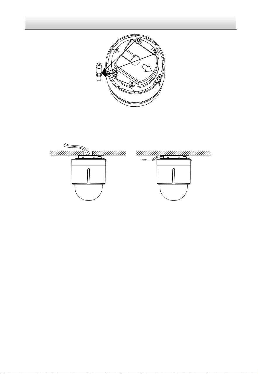
2. Route the cables. The cables of speed dome can be routed either from the top or the
side of the back box, as shown in Figure 2-18. For the cables routed from the top of
the back box, it is required to drill a cable hole in the ceiling.
Figure 2-18 Cabling for Ceiling Mounting
3. Install the speed dome.
1). Rotate the bubble counterclockwise to separate it from the back box.
2). Remove the protective lens cover, foam, and sticker from the dome drive.
3). Attach the bubble to the back box, and rotate clockwise to secure it.
4). Use the mounting base as a template to mark four screw holes onto the ceiling.
5). If you route cables from the top of the back box, mark the cable hole on the
ceiling and drill a hole.
6). Secure the mounting base to the ceiling with the set screws.
Network Speed Dome·Quick Start Guide
16
Screw Holes
Cable Hole
Figure 2-19 Secure the Mounting Base
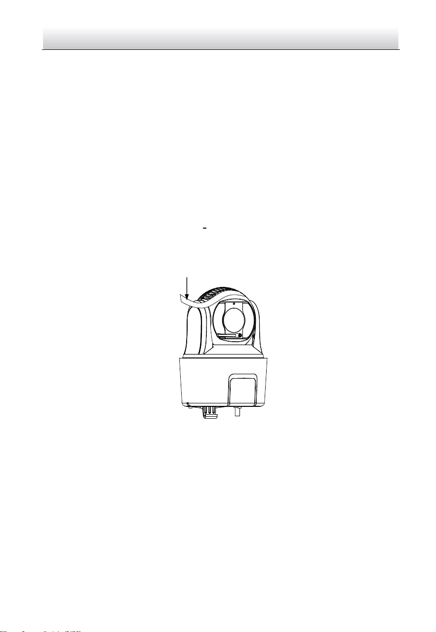
7). Route the cables for the speed dome. Align the bottom of the speed dome with
the mounting base.
8). Line up the direction of arrow with the spring end of the mounting base.
9). Push the speed dome upwards and then forwards in the direction of the arrow.
When the speed dome is placed in position, the spring will automatically snap
into the lock clip firmly as shown in Figure 2-20.
Line up
Push Forwards
Push Upwards
Figure 2-20 Attach the Back Box to the Mounting Base
4. Remove the protective film on the bubble after the installation is finished.
2.2 Installing Type II Speed Dome
Wall Mounting
Notes:
For cement wall, you need to use the expansion screw to fix the bracket. The
mounting hole of the expansion pipe on the wall should align with the mounting
hole on the bracket.
Network Speed Dome·Quick Start Guide
17
For wooden wall, you can just use the self-tapping screw to fix the bracket.
Make sure that the wall is strong enough to withstand more than eight times the
weight of the speed dome and the accessories.
The bracket shown in installation is the recommended bracket for this series of
speed dome, and a pendent adapter is required if any other bracket is selected. The
dimension of pendant adapter is G1
1
2
.
Water-proof treatment is required for cable connectors. Refer to Section 2.9 and
2.10 for details.
Steps:
1. Loosen the four lock screws on the speed dome flange as shown in Figure 2-21.
Note:
Do not remove the lock screws from the speed dome.
Lock Screws
Figure 2-21 Loosen the Lock Screws
2. Pull the bubble to separate it from the back box, and remove the protective foam,
sticker and lens cover from the dome drive.
Back Box
Lens Cover
Protective Foam
Bubble
Sticker
Figure 2-22 Remove the Protective Accessories
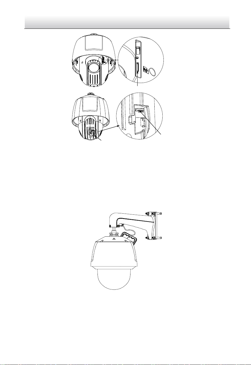
3. Install the memory card.
Network Speed Dome·Quick Start Guide
18
Memory Card Slot
Debug
Reset
Open Cover
Memory Card Slot
Figure 2-23 Install the Memory Card.
4. Align the cuts on the bubble with the lock screws on the back box to reinstall the
bubble. Tighten the lock screws.
5. Refer to steps 6 in section 2.1.1 Wall Mounting to install the bracket.
6. Install the speed dome to the bracket.
1). Hook the back box of the speed dome to the bracket with the safety rope. Route
the cables through the bracket.
2). Connect the corresponding cables.
Figure 2-24 Hang the Safety Rope
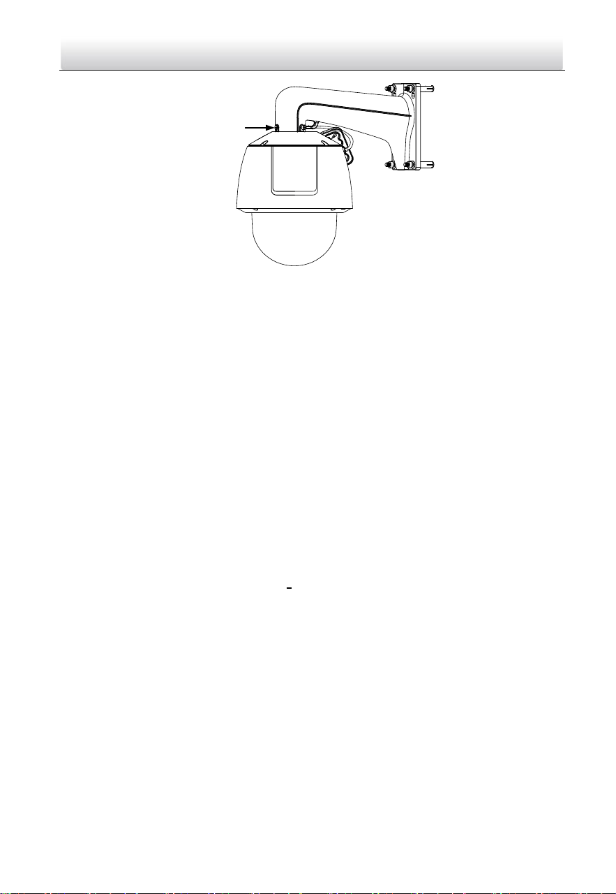
3). Loosen the two lock screws on the bracket.
4). Install the speed dome to the bracket. Rotate the speed dome clockwise tightly.
5). Secure the two lock screws with the wrench.
Network Speed Dome·Quick Start Guide
19
Lock Screw
Figure 2-25 Install the Speed Dome to the Bracket
7. Remove the protective film on the bubble after the installation is finished.
2.3 Installing Type III Speed Dome
Wall Mounting
Notes:
For cement wall, you need to use the expansion screw to fix the bracket. The
mounting hole of the expansion pipe on the wall should align with the mounting
hole on the bracket.
For wooden wall, you can just use the self-tapping screw to fix the bracket.
Make sure that the wall is strong enough to withstand more than eight times the
weight of the speed dome and the accessories.
The bracket in the installation is the recommended bracket for this series of speed
dome, and a pendent adapter is required if any other bracket is selected. The
dimension of pendant adapter is G1
1
2
.
Water-proof treatment is required for cable connectors. Refer to Section 2.9 and
2.10 for details.
Steps:
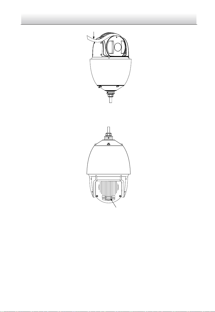
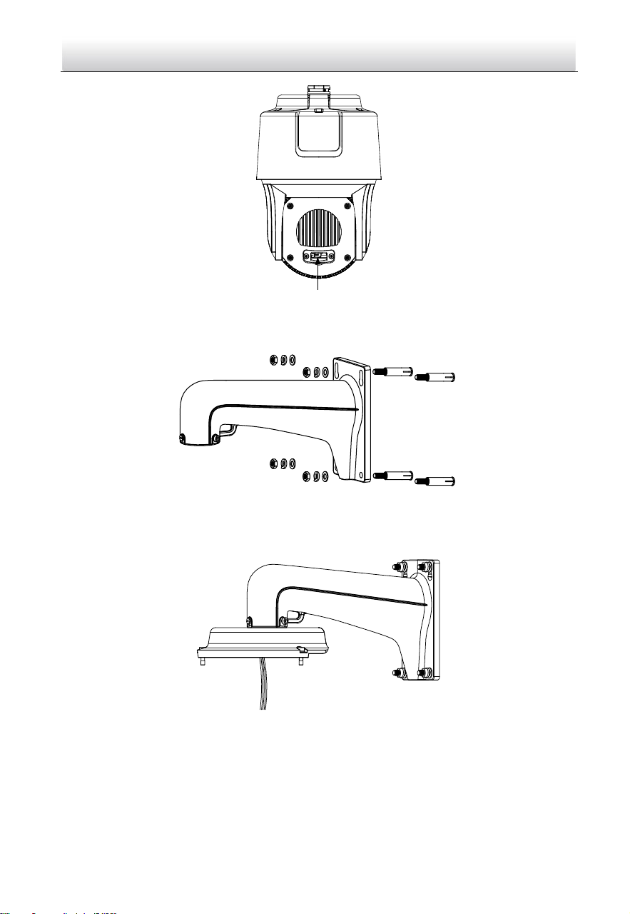
1. Remove the protective sticker as shown in Figure 2-26.
Network Speed Dome·Quick Start Guide
20
Protective Sticker
Figure 2-26 Remove Protective Sticker
2. Remove the cover on the back of speed dome as shown in Figure 2-27. Insert the
memory card to the memory card slot and install the cover back.
SD CARD
Memory Card Slot
Figure 2-27 Memory Card Slot
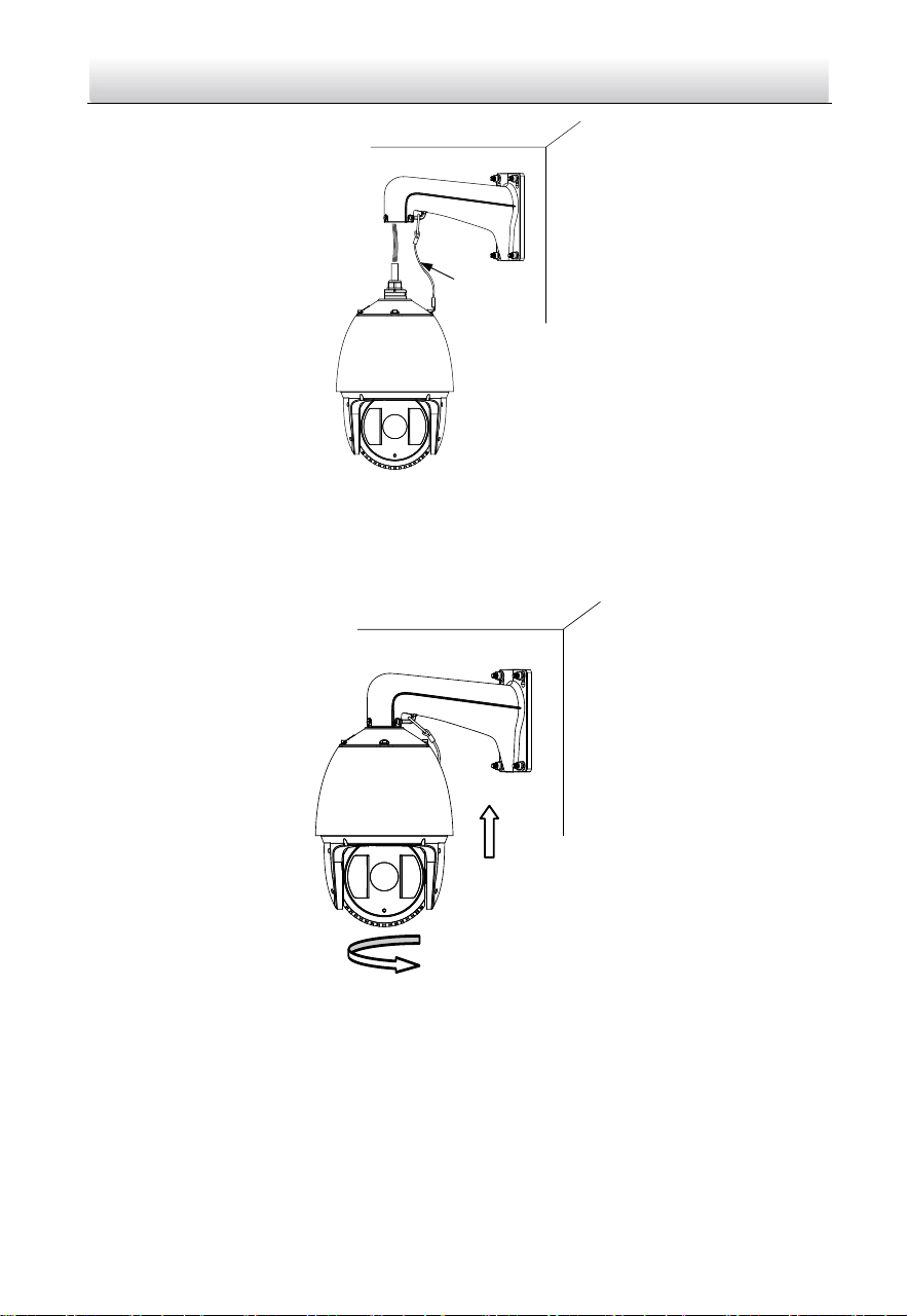
3. Refer to steps 6 in section 2.1.1 Wall Mounting to install the bracket.
4. Hook the two ends of the safety rope to the speed dome back box and the bracket
respectively. Route the cables through the bracket.
Network Speed Dome·Quick Start Guide
21
Safety Rope
Figure 2-28 Install the Safety Rope
5. Loosen the lock screws on the bracket.
6. Align the speed dome with bracket and rotate it counterclockwise or clockwise to
the bracket tightly as shown in Figure 2-29.
Figure 2-29 Install the Speed dome
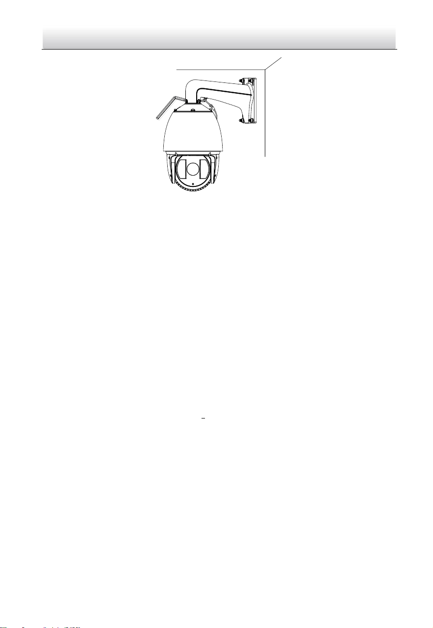
7. Use the wrench to tighten the lock screws to secure the speed dome and the
bracket.
Network Speed Dome·Quick Start Guide
22
Figure 2-30 Secure the Speed dome
8. Remove the protective film on the bubble after the installation is finished.
2.4 Installing Type IV Speed Dome
Wall Mounting
Notes:
For cement wall, you need to use the expansion screw to fix the bracket. The
mounting hole of the expansion pipe on the wall should align with the mounting
hole on the bracket.
For wooden wall, you can just use the self-tapping screw to fix the bracket.
Make sure that the wall is strong enough to withstand more than eight times the
weight of the speed dome and the accessories.
The bracket in the installation is the recommended bracket for this series of speed
dome, and a pendent adapter is required if any other bracket is selected. The
dimension of pendant adapter is G1
1
2
.
Steps:
1. Remove the protective sticker as shown in Figure 2-31.

Network Speed Dome·Quick Start Guide
23
Protective Sticker
Figure 2-31 Remove Protective Sticker
2. Remove the cover on the back of speed dome as shown in Figure 2-32. Insert the
memory card to the memory card slot and install the cover back.
Memory Card Slot
Figure 2-32 Memory Card Slot
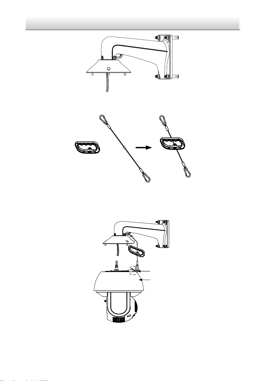
3. Secure the bracket with four hex nuts and washers.
Figure 2-33 Secure the Bracket
4. Apply thread tape to the thread of the head cover and rotate the head cover to the
bracket. Secure the head cover to the bracket with set screws (supplied).
Network Speed Dome·Quick Start Guide
24
Figure 2-34 Secure the Head Cover
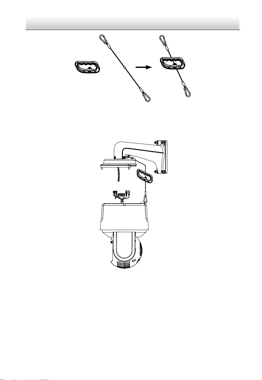
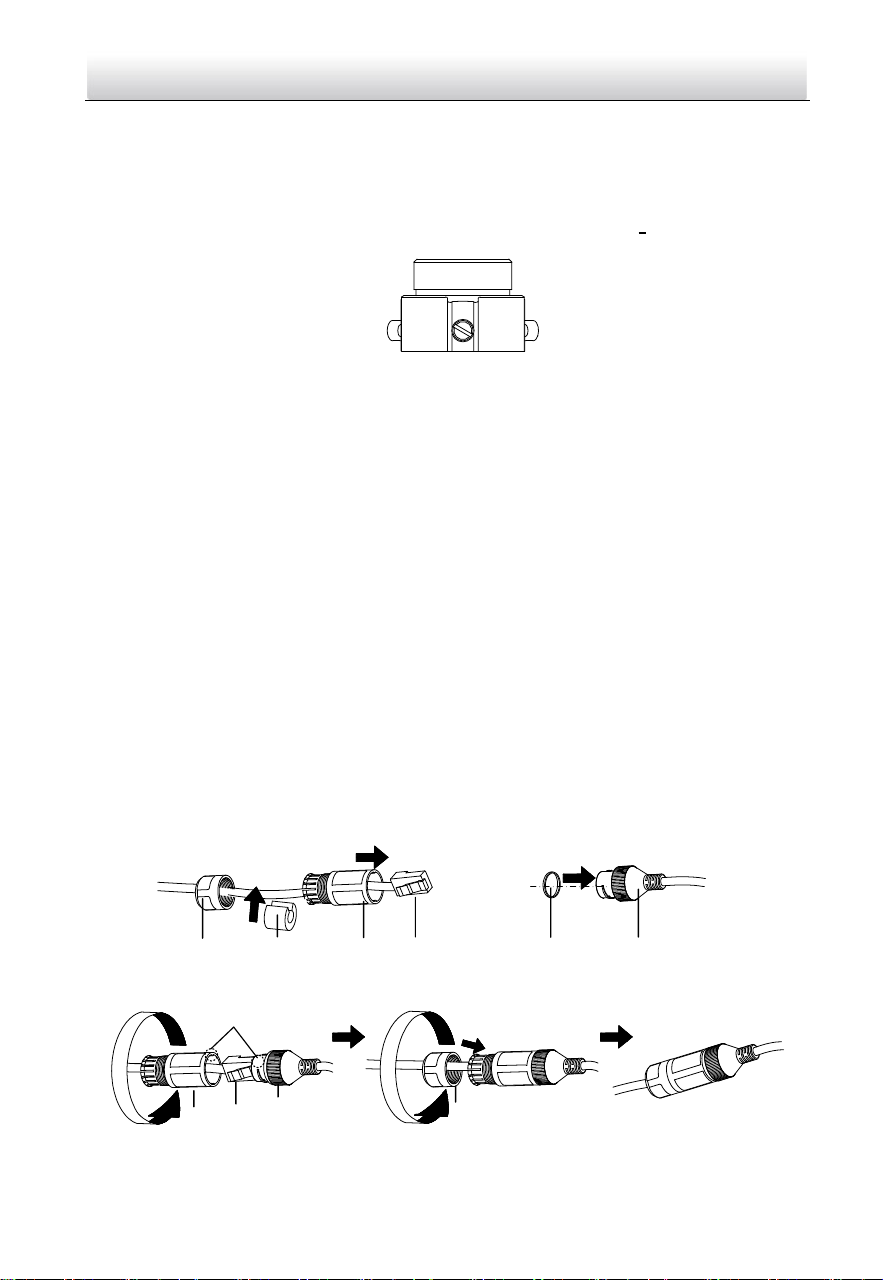
5. Buckle the handle to the safety rope.
+
Figure 2-35 Buckle the Handle
6. Hook the two ends of the safety rope to the speed dome back box and the bracket
respectively.
7. Hitch the speed dome onto the head cover with the hook on the back box.
Back Box
Hook
Figure 2-36 Hang the Speed Dome
8. Route and connect cables through the head cover and bracket.
Network Speed Dome·Quick Start Guide
25
Note:
Water-proof treatment is required for cable connectors. Refer to Section 2.9 and
2.10 for details.
Figure 2-37 Route the Cables
9. Align the speed dome back box with the head cover. Use the wrench to tighten the
lock screws to secure the speed dome and the bracket.
Lock Screw
Figure 2-38 Secure the Speed dome
10. Remove the protective film on the bubble after the installation is finished.
Network Speed Dome·Quick Start Guide
26
2.5 Installing Type V Speed Dome
Wall Mounting
Notes:
For cement wall, you need to use the expansion screw to fix the bracket. The
mounting hole of the expansion pipe on the wall should align with the mounting
hole on the bracket.
For wooden wall, you can just use the self-tapping screw to fix the bracket.
Make sure that the wall is strong enough to withstand more than eight times the
weight of the speed dome and the accessories.
The bracket in the installation is the recommended bracket for this series of speed
dome, and a pendent adapter is required if any other bracket is selected. The
dimension of pendant adapter is G1
1
2
.
Steps:
1. Remove the protective sticker as shown in Figure 2-39.
Protective Sticker
Figure 2-39 Remove Protective Sticker
2. Remove the cover on the back of speed dome as shown in Figure 2-40. Insert the
memory card to the memory card slot and install the cover back.
Network Speed Dome·Quick Start Guide
27
Memory Card Slot
Figure 2-40 Memory Card Slot
3. Secure the bracket with four hex nuts and washers.
Figure 2-41 Secure the Bracket
4. Apply thread tape to the thread of the head cover and rotate the head cover to the
bracket. Secure the head cover to the bracket with set screws (supplied).
Figure 2-42 Secure the Head Cover
5. Buckle the handle to the safety rope.
Network Speed Dome·Quick Start Guide
28
+
Figure 2-43 Buckle the Handle
6. Hook the two ends of the safety rope to the speed dome back box and the bracket
respectively.
7. Hitch the speed dome onto the head cover with the hook on the back box.
Figure 2-44 Hang the Speed Dome
8. Route and connect the cables through the head cover and bracket.
Note:
Water-proof treatment is required for cable connectors. Refer to Section 2.9 and
2.10 for details.
Network Speed Dome·Quick Start Guide
29
Figure 2-45 Route the Cables
9. Align the speed dome back box with the head cover. Use the wrench to tighten the
lock screws to secure the speed dome and the bracket.
Lock Screw
Figure 2-46 Secure the Speed dome
10. Remove the protective film on the bubble after the installation is finished.
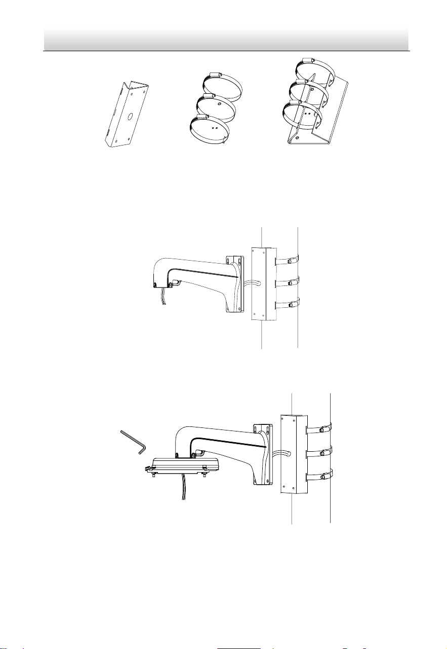
2.6 Installing Type VI and VII Speed Dome
Wall Mounting
Notes:
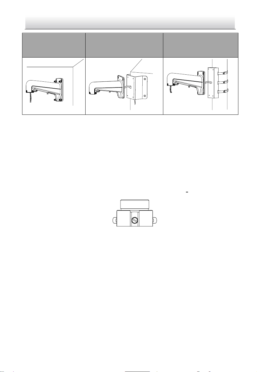
You can use wall mounting bracket alone, or you can use wall mounting bracket
together with a corner mounting bracket or a vertical pole mounting bracket to fix
the speed dome at a corner or on a pole.
Network Speed Dome·Quick Start Guide
30
Wall mounting bracket
Wall mounting bracket +
corner mounting bracket
Wall mounting bracket +
vertical pole mounting
bracket
Figure 2-47 Brackets for Installation
For cement wall, you need to use the expansion screw to fix the bracket. The
mounting hole of the expansion pipe on the wall should align with the mounting
hole on the bracket.
For wooden wall, you can just use the self-tapping screw to fix the bracket.
Make sure that the wall is strong enough to withstand more than eight times the
weight of the speed dome and the accessories.
If you use the brackets the dealer recommends, the pendant adapter in the package
is not needed during installation. The included pendent adapter might be useful if
you use other brackets. The dimension of pendant adapter is G1
1
2
.
Figure 2-48 Supplied Pendant Adapter
Steps:
1. Route the cables and install the brackets.
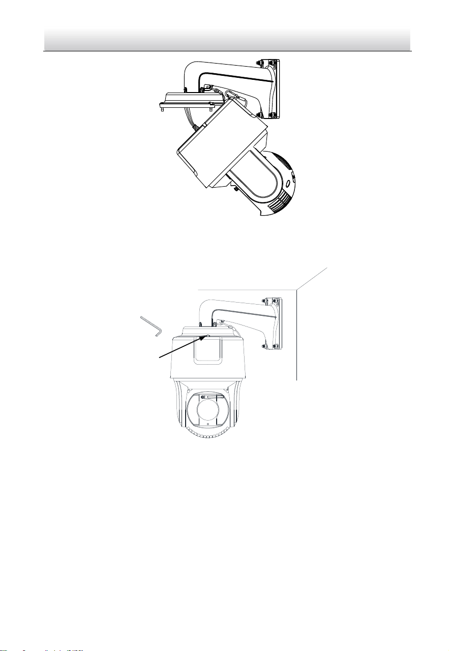
2. Fix the head cover to the wall mounting bracket.
1). Apply thread tape to the thread of the head cover and rotate the head cover to
the bracket.
2). Tighten the lock screws.
Network Speed Dome·Quick Start Guide
31
Head Cover
Lock Screw
Figure 2-49 Fix Head Cover to Bracket
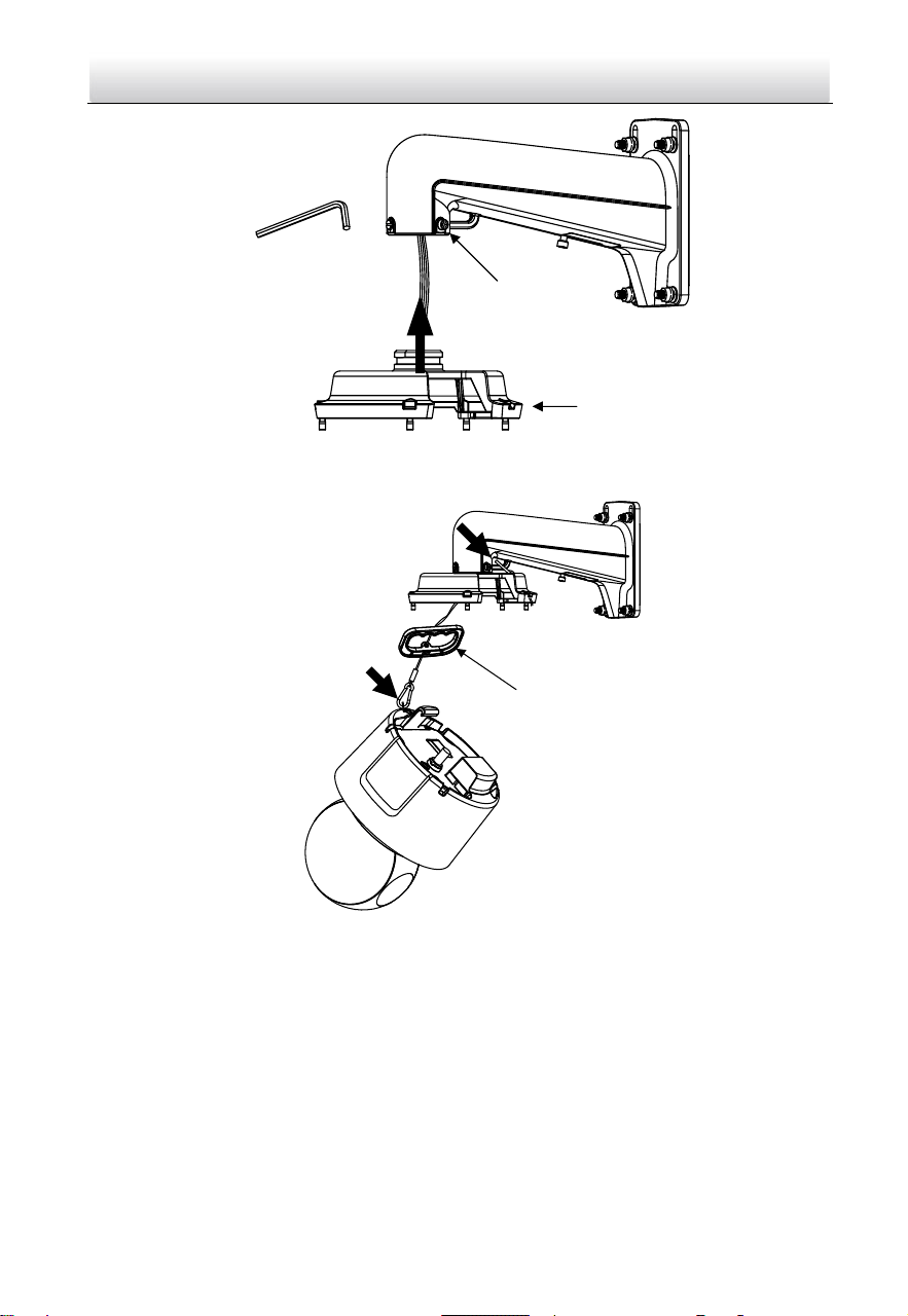
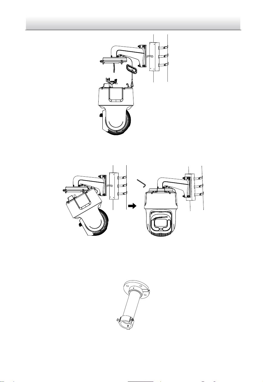
3. Hook the speed dome to the bracket with supplied safety rope.
Safety Rope
Figure 2-50 Use Safety Rope to Hook the Speed Dome to Bracket
4. Connect the cables.
Note:
You can pull the cables through the small door on the wall mounting bracket.
Unscrew to open it.
Water-proof treatment is required for cable connectors. Refer to Section 2.9 and
2.10 for details.
Network Speed Dome·Quick Start Guide
32
Figure 2-51 Door on Bracket
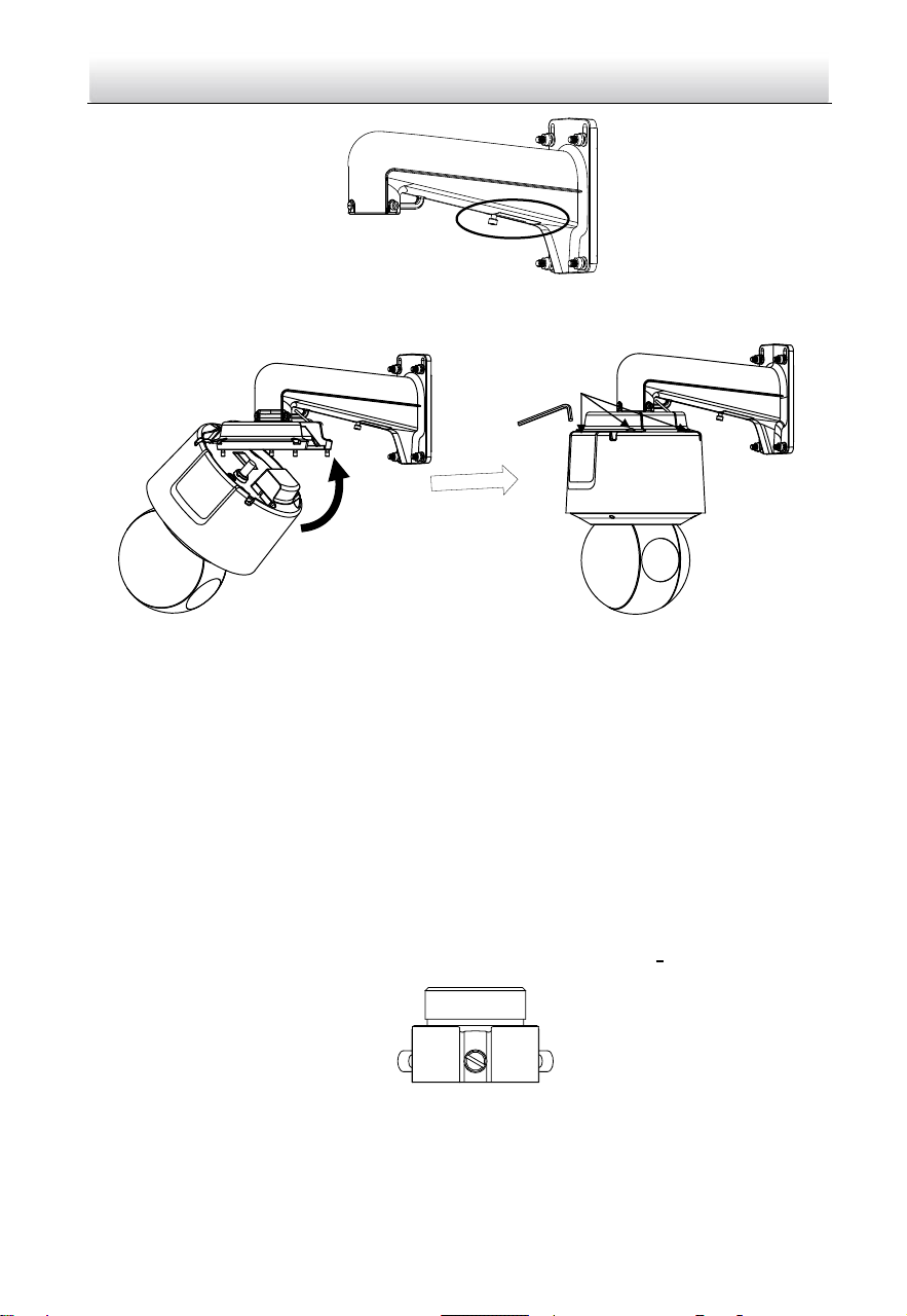
5. Align the speed dome with the head cover. Use the wrench to tighten the lock screws.
Lock Screws
Figure 2-52 Fix the Speed Dome to Head Cover
Pendant Mounting
Notes:
For cement ceiling, you need to use the expansion screw to fix the bracket. The
mounting hole of the expansion pipe on the wall should align with the mounting
hole on the bracket.
For wooden ceiling, you can just use the self-tapping screw to fix the bracket.
Make sure that the ceiling is strong enough to withstand more than eight times the
weight of the speed dome and the accessories.
If you use the brackets the dealer recommends, the pendant adapter in the package
is not needed during installation. The included pendent adapter might be useful if
you use other brackets. The dimension of pendant adapter is G1
1
2
.
Figure 2-53 Supplied Pendant Adapter
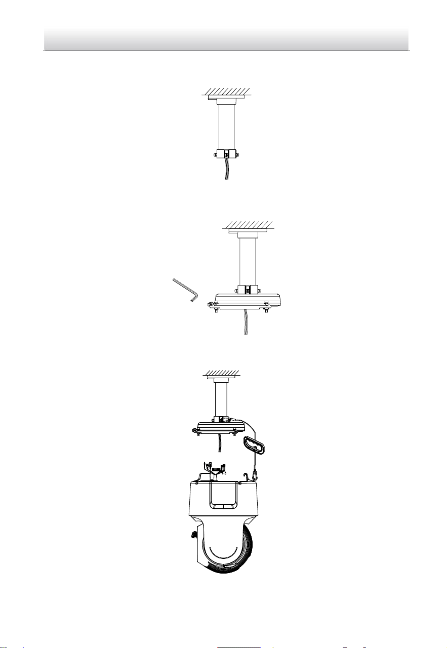
Steps:
1. Fix the pendant mounting bracket to ceiling.

Network Speed Dome·Quick Start Guide
33
Figure 2-54 Fix the Bracket to Ceiling
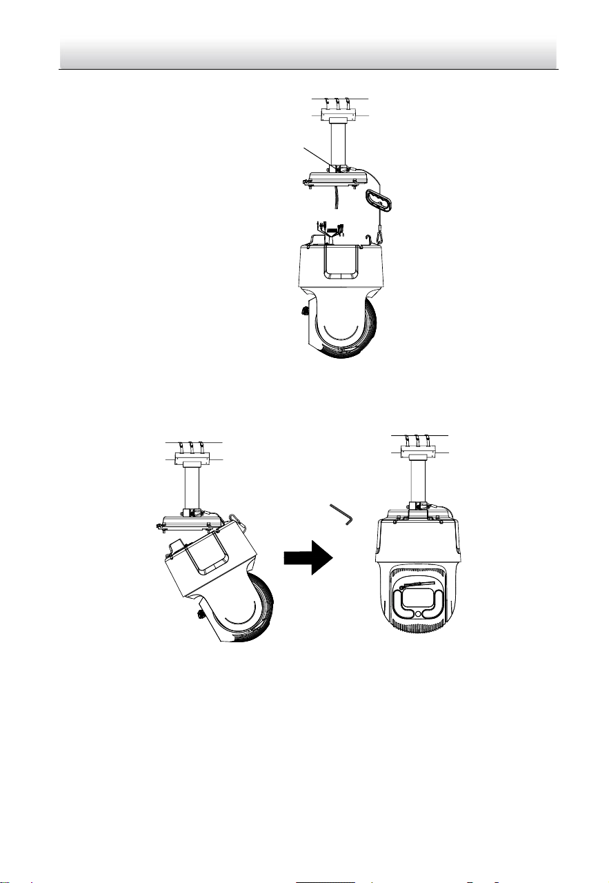
2. Fix the head cover to the pendant mounting bracket.
1). Apply thread tape to the thread of the head cover and rotate the head cover to
the bracket.
2). Tighten the lock screws.
Head Cover
Lock Screws
Figure 2-55 Fix Head Cover to Bracket
3. Hook the speed dome to the bracket with supplied safety rope.
Safety Rope
Figure 2-56 Use Safety Rope to Hook the Speed Dome to Bracket
Network Speed Dome·Quick Start Guide
34
4. Connect the cables.
Note:
Water-proof treatment is required for cable connectors. Refer to Section 2.9 and 2.10
for details.
5. Align the speed dome with the head cover. Use the wrench to tighten the lock screws.
Lock Screws
Figure 2-57 Fix the Speed Dome to Head Cover
2.7 Installing Type VIII Speed Dome
Wall Mounting
Notes:
For cement wall, you need to use the expansion screw to fix the bracket. The
mounting hole of the expansion pipe on the wall should align with the mounting
hole on the bracket.
For wooden wall, you can just use the self-tapping screw to fix the bracket.
Make sure that the wall is strong enough to withstand more than eight times the
weight of the speed dome and the accessories.
Water-proof treatment is required for cable connectors. Refer to Section 2.9 and
2.10 for details.
Steps:
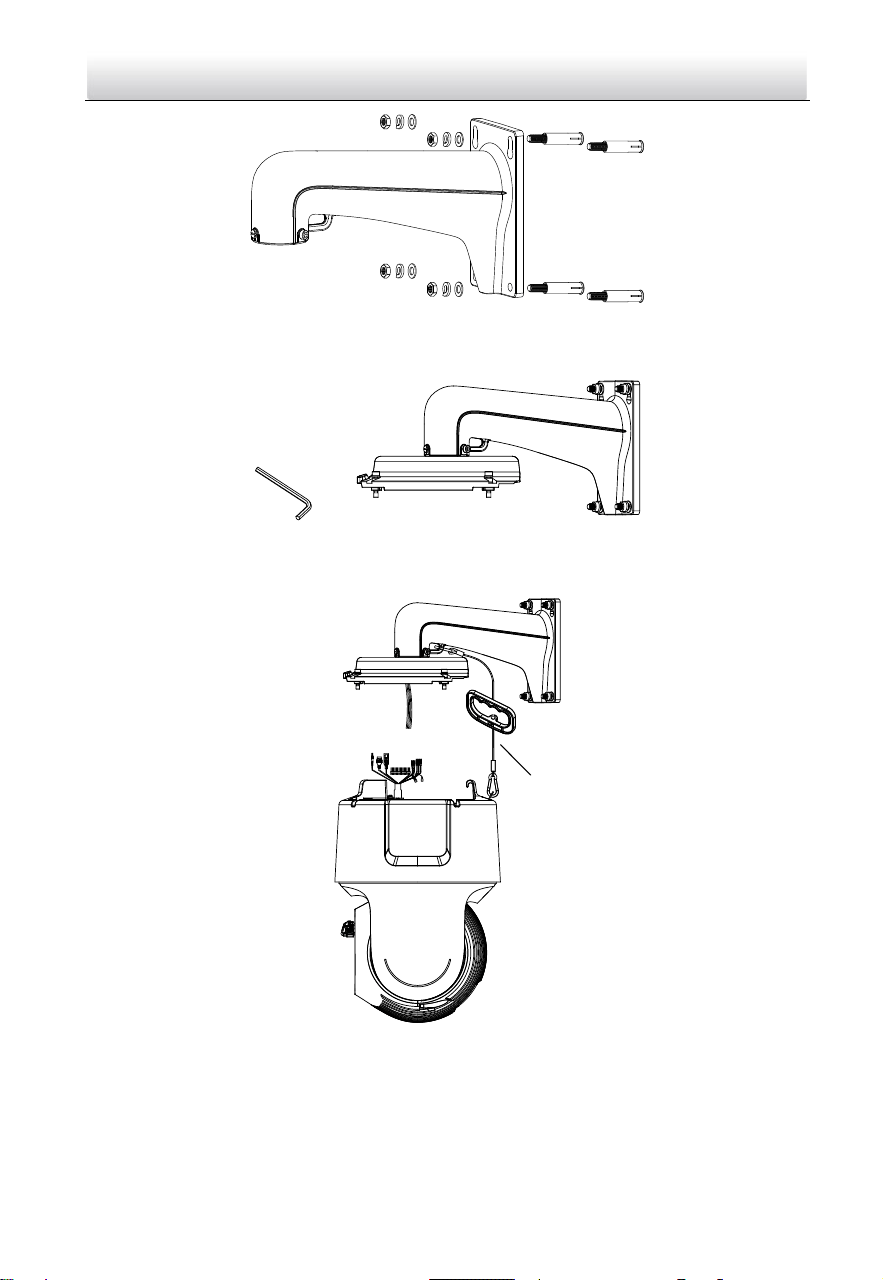
1. Install the bracket.
1) Drill four screw holes in the wall according to the holes on the bracket, and
then insert four expansion screws into the mounting holes.
2) Attach the bracket to the wall by aligning the four screw holes on the bracket
with four expansion screws on the wall.
3) Secure the bracket with four sets of hex nuts and washers.
Network Speed Dome·Quick Start Guide
35
Figure 2-58 Install the bracket
2. Use the wrench to fix head cover on the bracket.
Figure 2-59 Install head cover
3. Hook the speed dome to the bracket with supplied safety rope.
线
线
Figure 2-60 Use Safety Rope to hook the camera to the bracket
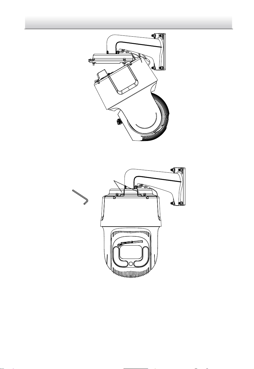
4. Route and connect the cables through the head cover and bracket.
Note:
Water-proof treatment is required for cable connectors. Refer to Section 2.9 and
2.10 for details.
Network Speed Dome·Quick Start Guide
36
Figure 2-61 Connect the cables
5. Align the speed dome with the head cover. Use the wrench to tighten the lock
screws.
Lock Screws
Figure 2-62 Secure the speed dome
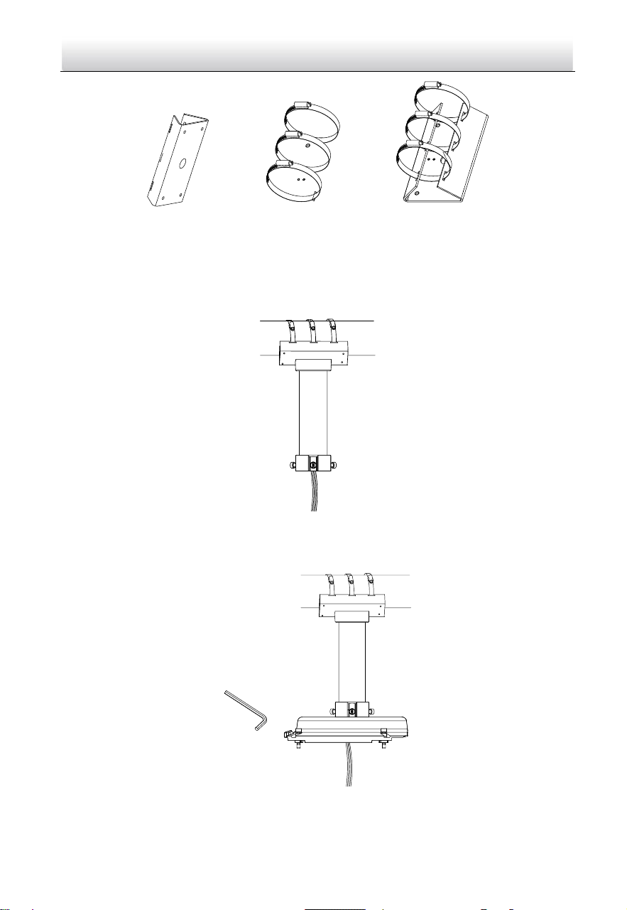
Horizontal Pole Mounting
Before you start:
Prepare one bracket and three hoops, and fix the hoops on the bracket.
Network Speed Dome·Quick Start Guide
37
Figure 2-63 Prepare accessory
Steps:
1. Lock the hoops and bracket on a horizontal pole, and route the cables through the
vertical mounting bracket. Then fix the vertical mounting bracket on the bracket
attached on the pole before.
Figure 2-64 Route the cables
2. Use the wrench to fix the head cover on the bracket.
Figure 2-65 Fix the head cover
Network Speed Dome·Quick Start Guide
38
3. Hook the speed dome to the bracket with supplied safety rope.
线
线
Safety Rope Hook
Figure 2-66 Use safe rope to hook the camera with bracket
4. Connect the cables, and align the speed dome with the head cover, using wrench to
tighten the screws on the head cover.
Figure 2-67 Finish the installation
Vertical Pole Mounting
Before you start:
Prepare one bracket and three hoops, and fix the hoops on the bracket.
Network Speed Dome·Quick Start Guide
39
Figure 2-68 Prepare accessory
Steps:
1. Lock the hoops and bracket on a vertical pole, and route the cables through the
vertical mounting bracket. Then fix the vertical mounting bracket on the bracket
attached on the pole before.
Figure 2-69 Route the cables
2. Use the wrench to fix the head cover on the bracket.
Figure 2-70 Fix the head cover
3. Hook the speed dome to the bracket with supplied safety rope.
Network Speed Dome·Quick Start Guide
40
线
线
Figure 2-71 Use safe rope to hook the camera with bracket
4. Connect the cables, and align the speed dome with the head cover, using wrench to
tighten the screws on the head cover.
Figure 2-72 Finish the installation
Pendant Mounting
Steps:
1. Drill four holes on the ceiling to match those on the pendant mount bracket.
Figure 2-73 Pendant mount
Network Speed Dome·Quick Start Guide
41
2. Route the cables through the bracket, then align the base plate to the holes and fix
it to the ceiling with four screws.
Figure 2-74 Route the cables and fix the bracket on the ceiling
3. Use the wrench to fix the head cover on the bracket.
Figure 2-75 Fix the head cover
4. Hook the speed dome to the bracket with supplied safety rope.
线
线
Figure 2-76 Use safe rope to hook the camera with bracket
Network Speed Dome·Quick Start Guide
42
5. Connect the cables, and align the speed dome with the head cover, using wrench to
tighten the screws on the head cover.
Figure 2-77 Finish the installation
2.8 Installing Type IX Speed Dome
Wall Mounting
Notes:
You can use a wall mounting bracket alone, or you can use a wall mounting bracket
together with a corner mounting bracket or a vertical pole mounting bracket to fix
the speed dome at a corner or on a pole.
The brackets are not included. You should purchase separately.
Wall mounting bracket
Wall mounting bracket +
corner mounting bracket
Wall mounting bracket +
vertical pole mounting
bracket
Figure 2-78 Brackets for Installation
For cement wall, you need to use the expansion screw to fix the bracket. The
mounting hole of the expansion pipe on the wall should align with the mounting
hole on the bracket.
For wooden wall, you can just use the self-tapping screw to fix the bracket.
Network Speed Dome·Quick Start Guide
43
Make sure that the wall is strong enough to withstand more than eight times the
weight of the speed dome and the accessories.
If you use the brackets the dealer recommends, the pendant adapter in the package
is not needed during installation. The included pendent adapter might be useful if
you use other brackets. The dimension of pendant adapter is G1
1
2
.
Figure 2-79 Supplied Pendant Adapter
Steps:
1. Refer to steps 6 in section 2.1.1 Wall Mounting to install the bracket.
2. Refer to steps 4 to 8 in section 2.3 Installing Type III Speed Dome to finish
installation.
Pendant Mounting
Steps:
1. Refer to steps 1 and 2 of pendant mounting in section 2.7 Installing Type VIII
Speed Dome Pendant Mounting to install the bracket.
2. Refer to steps 4 to 8 in section 2.3 Installing Type III Speed Dome to finish
installation.
2.9 Installation of Network Cable Waterproof Jacket
Purpose:
If the camera is installed outdoor, you should use the waterproof accessory or tapes to
waterproof the cables. Otherwise the cables might get wet or a short circuit occurs.
⑥
④
②
③
①
④
⑤
⑥
③
①
Align
Figure 2-80 Install Waterproof Jacket
Network Speed Dome·Quick Start Guide
44
Steps:
1. Feed the network cable through ① and ③ in order.
2. Fix ② on the network cable between ① and ③.
3. Place ⑤ onto the end of ⑥, and plug the RJ45 male connector into RJ45 female
connector.
4. Screw ③ to ⑥ clockwise.
5. Push ② into ③.
6. Secure ① with the ③ in clockwise direction.
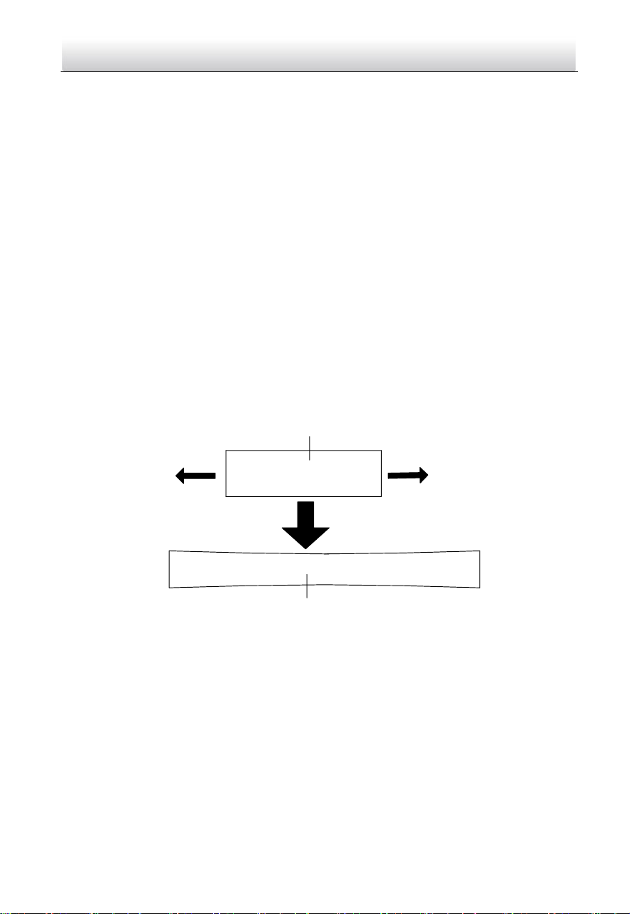
2.10 Installation of Water-proof Tape
Purpose:
If the camera is installed outdoor, you can use supplied water-proof tape to protect
cable connectors and unused cables after the camera is secured on the installation
surface.
Steps:
1. Tear off the yellow release paper on the back of the water-proof tape.
2. Stretch the water-proof tape to reach twice the initial length.
Stretch
Stretch
Initial Length
Waterproof Tape Length After Stretching
Figure 2-81 Stretch the Water-proof Tape
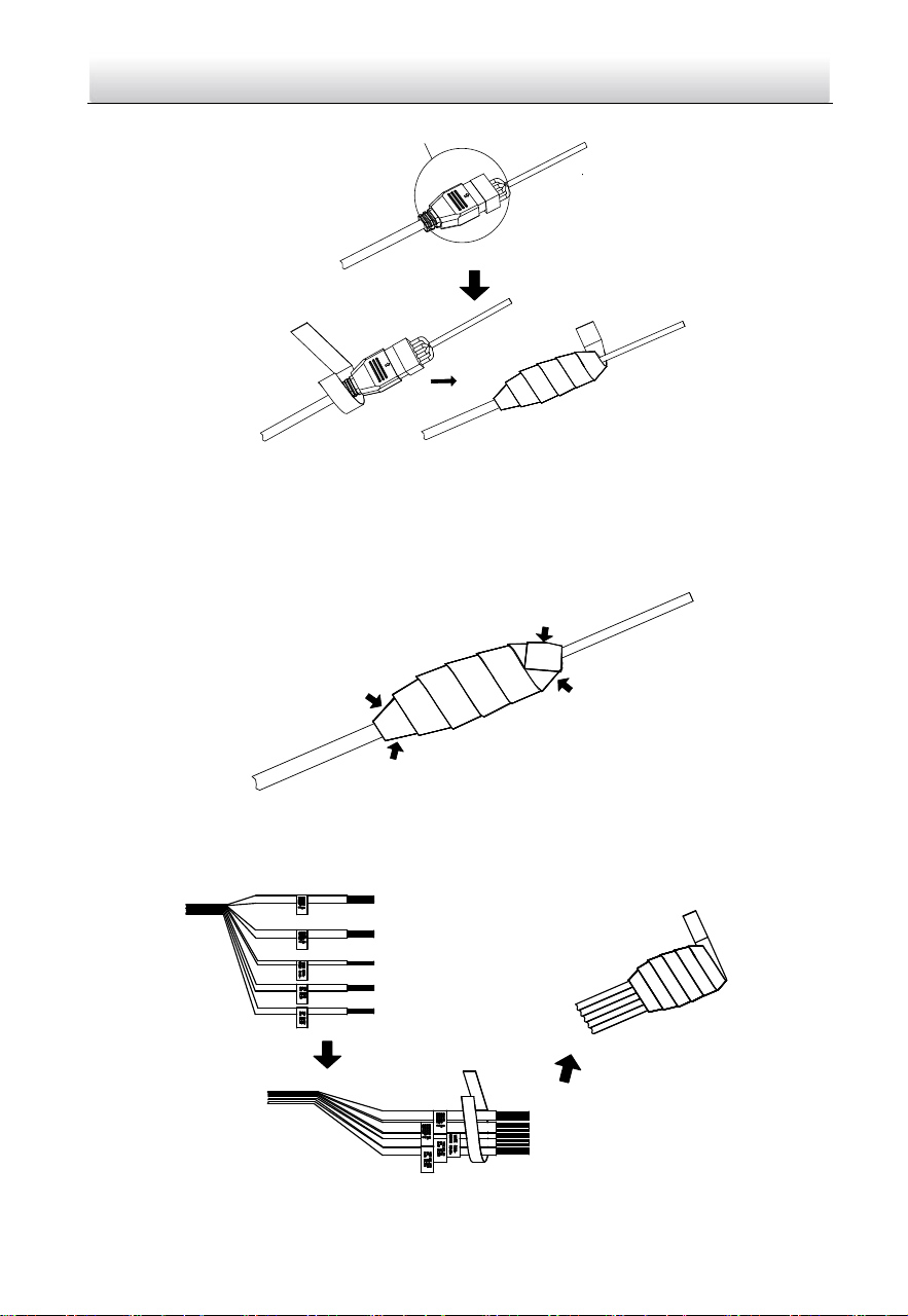
3. Wrap the water-proof tape around the cable connector tightly as the figure below.
Network Speed Dome·Quick Start Guide
45
Cable Connector
Figure 2-82 Wrap the Water-proof Tape
Note:
Make sure that all naked wires are all firmly wrapped in the water-proof tape.
4. Press the tape on both ends of the connector to make sure no water can get in as the
figure below.
Press
Press
Press
Press
Figure 2-83 Press the Water-proof Tape
5. Wrap the water-proof tape around the remaining unused cables tightly as the figure
below.
Figure 2-84 Wrap the Unused Cables
Network Speed Dome·Quick Start Guide
46
Note:
Make sure that all naked wires are all firmly wrapped in the water-proof tape.
6. Press the tape to make sure no water can get in as the figure below.
Press
Press
Press
Press
Figure 2-85 Press the Water-proof Tape
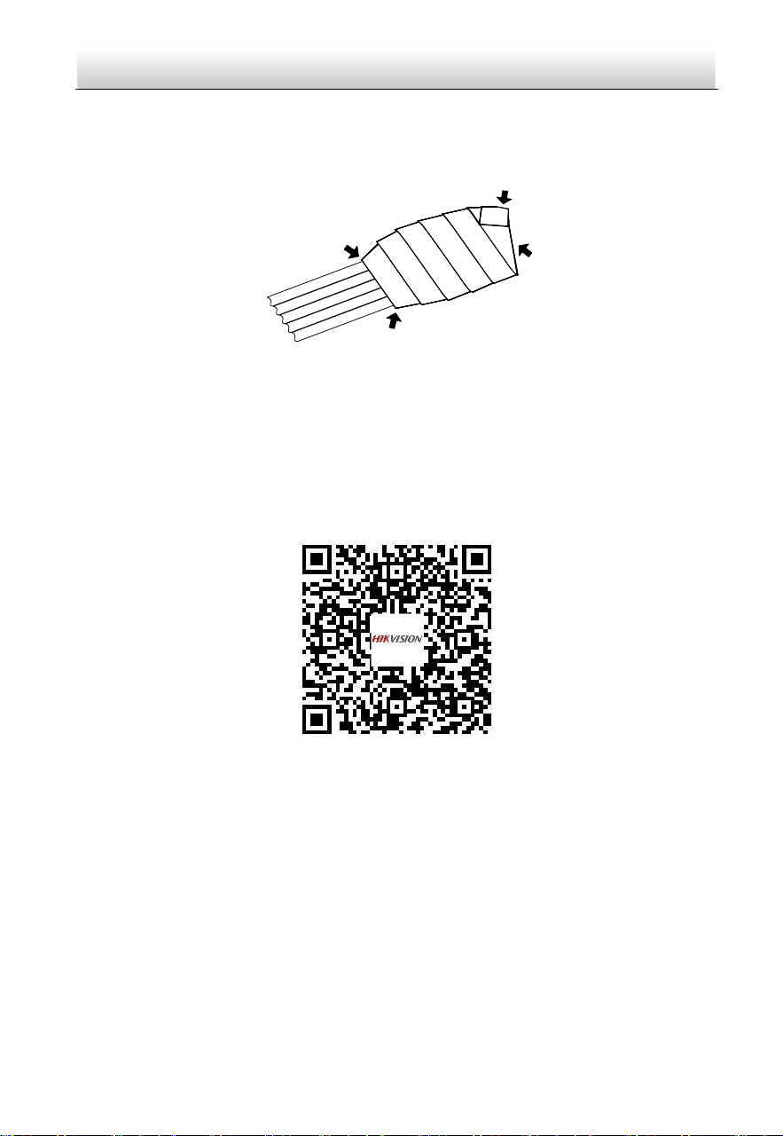
2.11 Protective Measures for Outdoor Installation
If the device is installed outdoors, necessary protective measures should be taken to
ensure safety. Scan the following QR code to get protective measures for outdoor
installation.
Network Speed Dome·Quick Start Guide
47
3 Activate and Access Network Camera
Scan the QR code to get Activate and Visit Network Camera. Note that mobile data
charges may apply if Wi-Fi is unavailable.

Network Speed Dome·Quick Start Guide
48
UD19618B