

User Manual of Network Speed Dome
1
User Manual
COPYRIGHT © 2015 Hangzhou Hikvision Digital Technology Co., Ltd.
ALL RIGHTS RESERVED.
Any and all information, including, among others, wordings, pictures, graphs are the properties of
Hangzhou Hikvision Digital Technology Co., Ltd. or its subsidiaries (hereinafter referred to be
“Hikvision”). This user manual (hereinafter referred to be “the Manual”) cannot be reproduced,
changed, translated, or distributed, partially or wholly, by any means, without the prior written
permission of Hikvision. Unless otherwise stipulated, Hikvision does not make any warranties,
guarantees or representations, express or implied, regarding to the Manual.
About this Manual
This Manual is applicable to 5-inch, 6.5-inch, 7-inch IR, 8-inch IR Network Speed Dome and
corrosion-proof speed dome.
The Manual includes instructions for using and managing the product. Pictures, charts, images and all
other information hereinafter are for description and explanation only. The information contained in
the Manual is subject to change, without notice, due to firmware updates or other reasons. Please
find the latest version in the company website (http://overseas.hikvision.com/en/).
Please use this user manual under the guidance of professionals.
Trademarks Acknowledgement
and other Hikvision’s trademarks and logos are the properties of Hikvision in various
jurisdictions. Other trademarks and logos mentioned below are the properties of their respective
owners.
Legal Disclaimer
TO THE MAXIMUM EXTENT PERMITTED BY APPLICABLE LAW, THE PRODUCT DESCRIBED, WITH ITS
HARDWARE, SOFTWARE AND FIRMWARE, IS PROVIDED “AS IS”, WITH ALL FAULTS AND ERRORS, AND
HIKVISION MAKES NO WARRANTIES, EXPRESS OR IMPLIED, INCLUDING WITHOUT LIMITATION,
MERCHANTABILITY, SATISFACTORY QUALITY, FITNESS FOR A PARTICULAR PURPOSE, AND
NON-INFRINGEMENT OF THIRD PARTY. IN NO EVENT WILL HIKVISION, ITS DIRECTORS, OFFICERS,
EMPLOYEES, OR AGENTS BE LIABLE TO YOU FOR ANY SPECIAL, CONSEQUENTIAL, INCIDENTAL, OR
INDIRECT DAMAGES, INCLUDING, AMONG OTHERS, DAMAGES FOR LOSS OF BUSINESS PROFITS,
BUSINESS INTERRUPTION, OR LOSS OF DATA OR DOCUMENTATION, IN CONNECTION WITH THE USE
OF THIS PRODUCT, EVEN IF HIKVISION HAS BEEN ADVISED OF THE POSSIBILITY OF SUCH DAMAGES.
REGARDING TO THE PRODUCT WITH INTERNET ACCESS, THE USE OF PRODUCT SHALL BE WHOLLY AT
YOUR OWN RISKS. HIKVISION SHALL NOT TAKE ANY RESPONSIBILITES FOR ABNORMAL OPERATION,
PRIVACY LEAKAGE OR OTHER DAMAGES RESULTING FROM CYBER ATTACK, HACKER ATTACK, VIRUS
INSPECTION, OR OTHER INTERNET SECURITY RISKS; HOWEVER, HIKVISION WILL PROVIDE TIMELY
TECHNICAL SUPPORT IF REQUIRED.
SURVEILLANCE LAWS VARY BY JURISDICTION. PLEASE CHECK ALL RELEVANT LAWS IN YOUR
JURISDICTION BEFORE USING THIS PRODUCT IN ORDER TO ENSURE THAT YOUR USE CONFORMS THE
APPLICABLE LAW. HIKVISION SHALL NOT BE LIABLE IN THE EVENT THAT THIS PRODUCT IS USED WITH

Network Speed Dome User Manual
2
ILLEGITIMATE PURPOSES.
IN THE EVENT OF ANY CONFLICTS BETWEEN THIS MANUAL AND THE APPLICABLE LAW, THE LATER
PREVAILS.
Network Speed Dome User Manual
3
Regulatory Information
FCC Information
FCC compliance: This equipment has been tested and found to comply with the limits for a digital
device, pursuant to part 15 of the FCC Rules. These limits are designed to provide reasonable
protection against harmful interference when the equipment is operated in a commercial
environment. This equipment generates, uses, and can radiate radio frequency energy and, if not
installed and used in accordance with the instruction manual, may cause harmful interference to radio
communications. Operation of this equipment in a residential area is likely to cause harmful
interference in which case the user will be required to correct the interference at his own expense.
FCC Conditions
This device complies with part 15 of the FCC Rules. Operation is subject to the following two
conditions:
1. This device may not cause harmful interference.
2. This device must accept any interference received, including interference that may cause undesired
operation.
EU Conformity Statement
This product and - if applicable - the supplied accessories too are marked with "CE"
and comply therefore with the applicable harmonized European standards listed
under the EMC Directive 2004/108/EC, the RoHS Directive 2011/65/EU.
2012/19/EU (WEEE directive): Products marked with this symbol cannot be disposed
of as unsorted municipal waste in the European Union. For proper recycling, return
this product to your local supplier upon the purchase of equivalent new equipment,
or dispose of it at designated collection points. For more information see:
www.recyclethis.info.
2006/66/EC (battery directive): This product contains a battery that cannot be
disposed of as unsorted municipal waste in the European Union. See the product
documentation for specific battery information. The battery is marked with this
symbol, which may include lettering to indicate cadmium (Cd), lead (Pb), or mercury
(Hg). For proper recycling, return the battery to your supplier or to a designated collection point. For
more information see: www.recyclethis.info.
Industry Canada ICES-003 Compliance
This device meets the CAN ICES-3 (A)/NMB-3(A) standards requirements.
Network Speed Dome User Manual
4
Safety Instruction
These instructions are intended to ensure that the user can use the product correctly to avoid danger
or property loss.
The precaution measure is divided into ‘Warnings’ and ‘Cautions’:
Warnings: Serious injury or death may be caused if any of these warnings are neglected.
Cautions: Injury or equipment damage may be caused if any of these cautions are neglected.
Warnings Follow these safeguards to prevent
serious injury or death.
Cautions Follow these precautions to prevent
potential injury or material damage.
Warnings:
Please adopt the power adapter which can meet the safety extra low voltage (SELV) standard. The
power consumption cannot be less than the required value.
Do not connect several devices to one power adapter as an adapter overload may cause
over-heating and can be a fire hazard.
When the product is installed on a wall or ceiling, the device should be firmly fixed.
To reduce the risk of fire or electrical shock, do not expose the indoor used product to rain or
moisture.
This installation should be made by a qualified service person and should conform to all the local
codes.
Please install blackouts equipment into the power supply circuit for convenient supply
interruption.
If the product does not work properly, please contact your dealer or the nearest service center.
Never attempt to disassemble the product yourself. (We shall not assume any responsibility for
problems caused by unauthorized repair or maintenance.)
Please do not look directly into the laser light within 6 meters because laser is hazardous to
humans.

Network Speed Dome User Manual
5
Cautions:
Make sure the power supply voltage is correct before using the product.
Do not drop the product or subject it to physical shock. Do not install the product on vibratory
surface or places.
Do not expose it to high electromagnetic radiating environment.
Do not aim the lens at the strong light such as sun or incandescent lamp. The strong light can
cause fatal damage to the product.
The sensor may be burned out by a laser beam, so when any laser equipment is being used, make
sure that the surface of the sensor not be exposed to the laser beam.
For working temperature, please refer to the specification manual for details.
To avoid heat accumulation, good ventilation is required for a proper operating environment.
While shipping, the product should be packed in its original packing.
Please use the provided glove when open up the product cover. Do not touch the product cover
with fingers directly, because the acidic sweat of the fingers may erode the surface coating of the
product cover.
Please use a soft and dry cloth when clean inside and outside surfaces of the product cover. Do
not use alkaline detergents.
Improper use or replacement of the battery may result in hazard of explosion. Please use the
manufacturer recommended battery type.

Network Speed Dome User Manual
6
Table of Contents
Chapter 1 Overview .................................................................................................................... 9
1.1 System Requirement ................................................................................................................ 9
1.2 Functions.................................................................................................................................. 9
Chapter 2 Network Connection ................................................................................................ 12
2.1 Setting the Network Speed Dome over the LAN.................................................................... 12
2.1.1 Wiring over the LAN .......................................................................................................... 12
2.1.2 Activating the Speed Dome ................................................................................................ 13
2.2 Setting the Network Speed Dome over the WAN .................................................................. 19
2.2.1 Static IP Connection ........................................................................................................... 19
2.2.2 Dynamic IP Connection ...................................................................................................... 20
Chapter 3 Access to the Network Speed Dome ......................................................................... 23
3.1 Accessing by Web Browsers ................................................................................................... 23
3.2 Accessing by Client Software ................................................................................................. 25
Chapter 4 Basic Operations ...................................................................................................... 27
4.1 Power-up Action .................................................................................................................... 27
4.2 Configuring Local Parameters ................................................................................................ 27
4.3 Live View Page ....................................................................................................................... 29
4.4 Starting Live View .................................................................................................................. 30
4.5 Operating PTZ Control ............................................................................................................ 32
4.5.1 PTZ Control Panel ............................................................................................................... 32
4.5.2 Auxiliary Functions ............................................................................................................. 34
4.5.3 Setting/Calling a Preset ..................................................................................................... 35
4.5.4 Setting/Calling a Patrol ...................................................................................................... 38
4.5.5 One-touch Patrol ................................................................................................................ 39
4.5.6 Setting/Calling a Pattern ................................................................................................... 40
4.6 Playback ................................................................................................................................. 41
Play Back Video Files ...................................................................................................................... 41
Downloading Video Files ................................................................................................................ 43
4.7 Picture .................................................................................................................................... 43
Chapter 5 System Configurations .............................................................................................. 45
5.1 Storage Settings ..................................................................................................................... 45
5.1.1 Configuring Recording Schedule ........................................................................................ 45
5.1.2 Configuring Capture Schedule ........................................................................................... 49
5.1.3 Configuring Net HDD ......................................................................................................... 50
5.2 Basic Event Configuration ...................................................................................................... 52
5.2.1 Configuring Motion Detection ........................................................................................... 52
5.2.2 Configuring Video Loss Alarm ............................................................................................ 57
5.2.3 Configuring Video Tampering Alarm ................................................................................. 58
5.2.4 Configuring Alarm Input .................................................................................................... 59

Network Speed Dome User Manual
7
5.2.5 Configuring Alarm Output ................................................................................................. 60
5.2.6 Handling Exception ............................................................................................................ 61
5.3 Smart Event Configuration ..................................................................................................... 62
5.3.1 Detecting Audio Exception ................................................................................................. 62
5.3.2 Configuring Face Detection ................................................................................................ 64
5.3.3 Configuring Intrusion Detection ......................................................................................... 64
5.3.4 Configuring Line Crossing Detection .................................................................................. 66
5.3.5 Region Entrance Detection ................................................................................................. 68
5.3.6 Region Exiting Detection .................................................................................................... 70
5.4 PTZ Configuration .................................................................................................................. 71
5.4.1 Configuring Basic PTZ Parameters ..................................................................................... 71
5.4.2 Configuring PTZ Limits ....................................................................................................... 73
5.4.3 Configuring Initial Position................................................................................................. 74
5.4.4 Configuring Park Actions.................................................................................................... 74
5.4.5 Configuring Privacy Mask .................................................................................................. 75
5.4.6 Configuring Scheduled Tasks .............................................................................................. 77
5.4.7 Clearing PTZ Configurations ............................................................................................... 79
5.4.8 Configuring Smart Tracking ............................................................................................... 79
5.4.9 Configuring PTZ Control Priority ........................................................................................ 80
Chapter 6 Speed Dome Configuration ...................................................................................... 82
6.1 Configuring Network Settings ................................................................................................ 82
6.1.1 Basic Settings ..................................................................................................................... 82
6.1.2 Advanced Settings .............................................................................................................. 88
6.2 Configuring Video and Audio Settings ................................................................................... 98
6.2.1 Configuring Video Settings ................................................................................................ 98
6.2.2 Configuring Audio Settings .............................................................................................. 100
6.2.3 Configuring ROI Settings .................................................................................................. 101
6.2.4 Dual-VCA Settings ............................................................................................................ 102
6.3 Configuring Image Settings .................................................................................................. 103
6.3.1 Configuring Display Settings ............................................................................................ 103
6.3.2 Configuring OSD Settings ................................................................................................. 110
6.3.3 Configuring Text Overlay Settings .................................................................................... 112
6.4 Configuring System Settings ................................................................................................ 113
6.4.1 System Setting ................................................................................................................. 113
6.4.2 Maintenance .................................................................................................................... 117
6.4.3 Security ............................................................................................................................ 120
6.4.4 User Management ........................................................................................................... 123
Appendix ....................................................................................................................................... 127
Appendix 1 SADP Software Introduction .......................................................................................... 127
Appendix 2 Statics, Interference Lightning and Surge Protection .................................................... 129
Appendix 3 Waterproof .................................................................................................................... 133
Appendix 4 Bubble Maintenance ..................................................................................................... 134
Appendix 5 RS485 Bus Connection ................................................................................................... 135

Network Speed Dome User Manual
8
Appendix 6 24VAC Wire Gauge & Transmission Distance ................................................................ 138
Appendix 7 12VDC Wire Gauge & Transmission Distance ................................................................ 139
Appendix 8 Table of Wire Gauge Standards ..................................................................................... 140
Appendix 9 Alarm In/Out Connections............................................................................................. 141

Network Speed Dome User Manual
9
Chapter 1 Overview
1.1 System Requirement
System requirement of web browser accessing is as follows:
Operating System: Microsoft Windows XP SP1 and above version / Vista / Win7 /
Server 2003 / Server 2008 32bits
CPU: Intel Pentium IV 3.0 GHz or higher
RAM: 1G or higher
Display: 1024×768 resolution or higher
Web Browser: Internet Explorer 8.0 and above version, Apple Safari 5.02 and above
version, Mozilla Firefox 5 and above version and Google Chrome 18 and above
versions.
1.2 Functions
The functions vary depending on the models of speed dome.
Limit Stops
The dome can be programmed to move within the limit stops (left/right, up/down).
Scan Modes
The dome provides 5 scan modes: auto scan, tilt scan, frame scan, random scan and
panorama scan.
Preset Freezing
This feature freezes the scene on the monitor when the dome is moving to a preset.
This allows for smooth transition from one preset scene to another. It also
guarantees that masked area will not be revealed when the dome is moving to a
preset.
Presets
A preset is a predefined image position. When the preset is called, the dome will
automatically move to the defined position. The presets can be added, modified,
deleted and called.
Label Display
The on-screen label of the preset title, azimuth/elevation, zoom, time and dome
name can be displayed on the monitor. The displays of time and speed dome name
can be programmed.
Auto Flips
In manual tracking mode, when a target object goes directly beneath the dome, the
video will automatically flips 180 degrees in horizontal direction to maintain
continuity of tracking. This function can also be realized by auto mirror image

Network Speed Dome User Manual
10
depending on different camera models.
Privacy Mask
This function allows you to block or mask certain area of a scene, for preventing the
personal privacy from recording or live viewing. A masked area will move with pan
and tilt functions and automatically adjust in size as the lens zooms telephoto and
wide.
3D Positioning
In the client software, use the left key of mouse to click on the desired position in the
video image and drag a rectangle area in the lower right direction, then the dome
system will move the position to the center and allow the rectangle area to zoom in.
Use the left key of mouse to drag a rectangle area in the upper left direction to move
the position to the center and allow the rectangle area to zoom out.
Proportional Pan/Tilt
Proportional pan/tilt automatically reduces or increases the pan and tilt speeds
according to the amount of zoom. At telephoto zoom settings, the pan and tilt
speeds will be slower than at wide zoom settings. This keeps the image from moving
too fast on the live view image when there is a large amount of zoom.
Auto Focus
The auto focus enables the camera to focus automatically to maintain clear video
images.
Day/Night Auto Switch
The speed domes deliver color images during the day. And as light diminishes at night,
the speed domes switch to night mode and deliver black and white images with high
quality.
Slow Shutter
In slow shutter mode, the shutter speed will automatically slow down in low
illumination conditions to maintain clear video images by extending the exposure
time. The feature can be enabled or disabled.
Backlight Compensation (BLC)
If you focus on an object against strong backlight, the object will be too dark to be
seen clearly. The BLC (Backlight Compensation) function can compensate light to the
object in the front to make it clear, but this causes the over-exposure of the
background where the light is strong.
Wide Dynamic Range (WDR)
The wide dynamic range (WDR) function helps the camera provide clear images even
under back light circumstances. When there are both very bright and very dark areas
simultaneously in the field of view, WDR balances the brightness level of the whole
image and provide clear images with details.
This feature varies depending on speed dome models.
White Balance (WB)
White balance can remove the unrealistic color casts. White balance is the white
rendition function of the camera to adjust the color temperature according to the

Network Speed Dome User Manual
11
environment automatically.
Patrol
A patrol is a memorized series of pre-defined preset function. The scanning speed
between two presets and the dwell time at the preset are programmable.
Pattern
A pattern is a memorized series of pan, tilt, zoom, and preset functions. By default
the focus and iris are in auto status during the pattern is being memorized.
Power Off Memory
The dome supports the power off memory capability with the predefined resume
time. It allows the dome to resume its previous position after power is restored.
Time Task
A time task is a preconfigured action that can be performed automatically at a
specific date and time. The programmable actions include: auto scan, random scan,
patrol 1-8 ,pattern 1-4, preset 1-8,frame scan, panorama scan, tilt scan, day, night,
reboot, PT adjust, Aux Output, etc.
Park Action
This feature allows the dome to start a predefined action automatically after a period
of inactivity.
User Management
The dome allows you to edit users with different levels of permission, in the admin
login status. Multiple users are allowed to access and control the same network
speed dome via network simultaneously.
3D Digital Noise Reduction
Comparing with the general 2D digital noise reduction, the 3D digital noise reduction
function processes the noise between two frames besides processing the noise in
one frame. The noise will be much less and the video will be clearer.
Dual-VCA
Combine the detected VCA information into the video stream, which can be used for
the second-time analysis on the back-end device.
User Manual of Network Speed Dome
12
Chapter 2 Network Connection
You shall acknowledge that the use of the product with Internet access might be
under network security risks. For avoidance of any network attacks and
information leakage, please strengthen your own protection. If the product does
not work properly, please contact with your dealer or the nearest service center.
To ensure the network security of the speed dome, we recommend you to have
the speed dome assessed and maintained termly. You can contact us if you need
such service.
Before you start:
If you want to set the network speed dome via a LAN (Local Area Network),
please refer to Section 2.1 Setting the Network Speed Dome over the LAN.
If you want to set the network speed dome via a WAN (Wide Area Network),
please refer to Section 2.2 Setting the Network Speed Dome over the WAN.
2.1 Setting the Network Speed Dome over the LAN
Purpose:
To view and configure the speed dome via a LAN, you need to connect the network
speed dome in the same subnet with your computer, and install the SADP or client
software to search and change the IP of the network speed dome.
For the detailed introduction of SADP, please refer to Appendix 1.
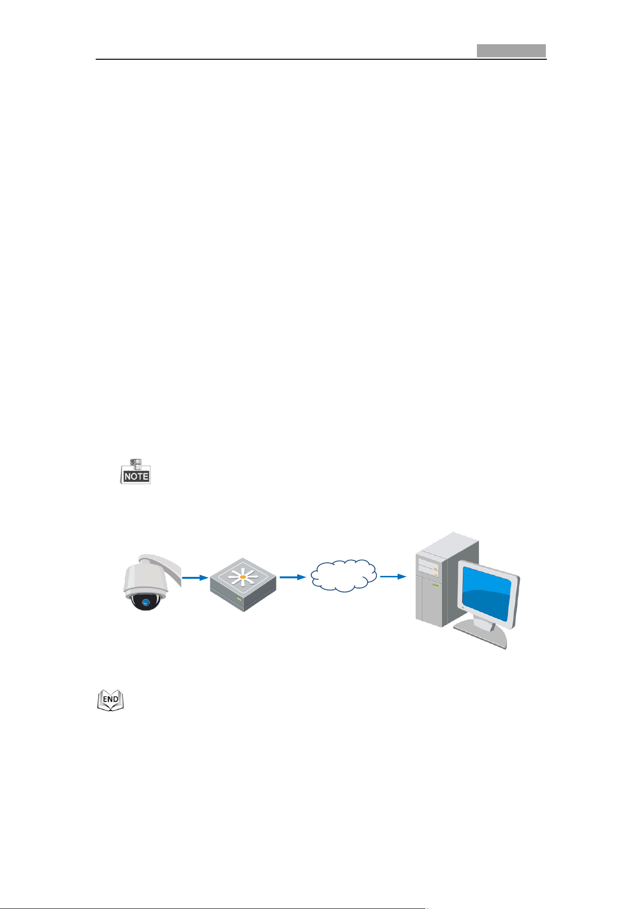
2.1.1 Wiring over the LAN
The following figures show the two ways of cable connection of a network speed
dome and a computer:
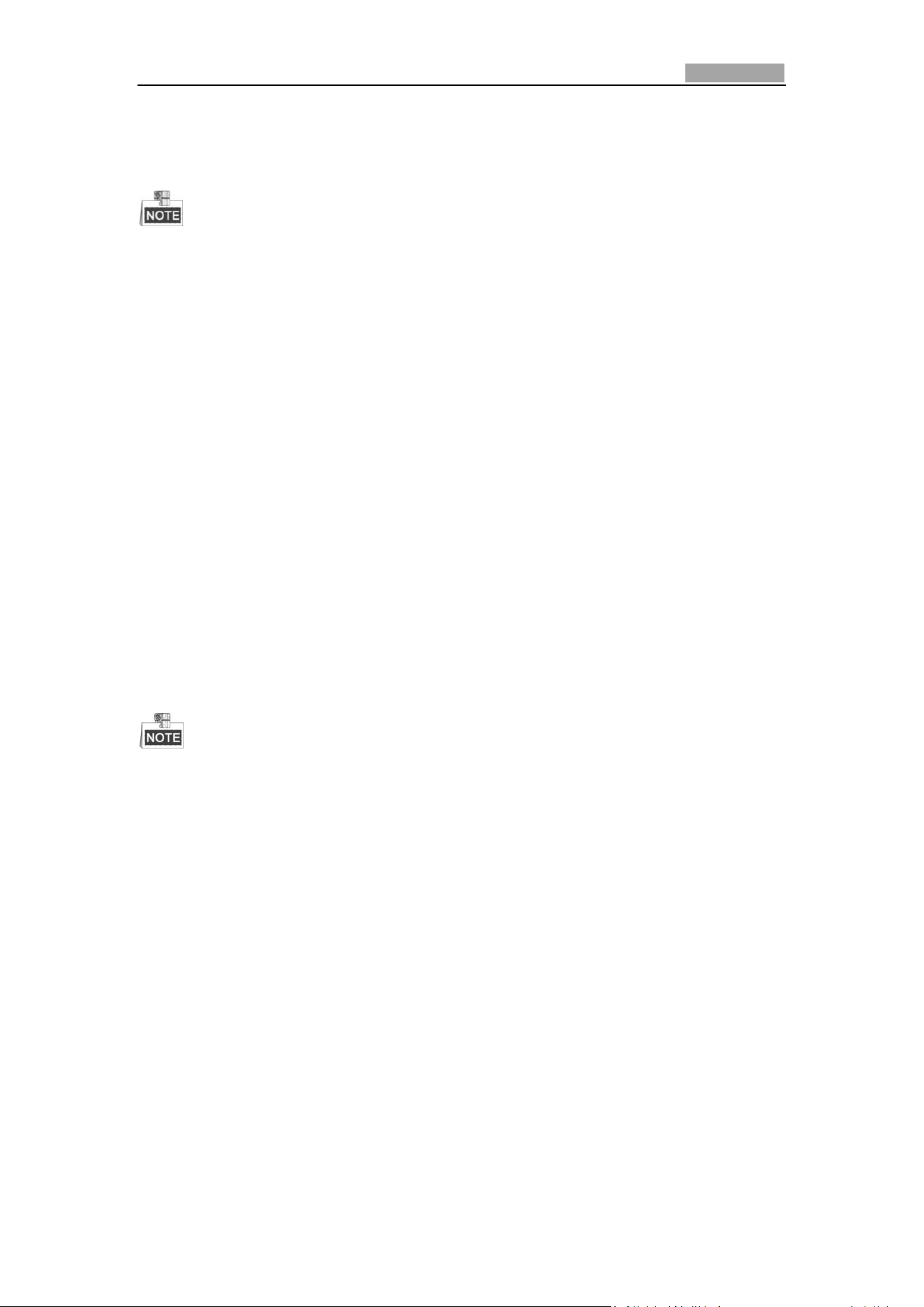
Purpose:
To test the network speed dome, you can directly connect the network speed
dome to the computer with a network cable as shown in Figure 2-1.
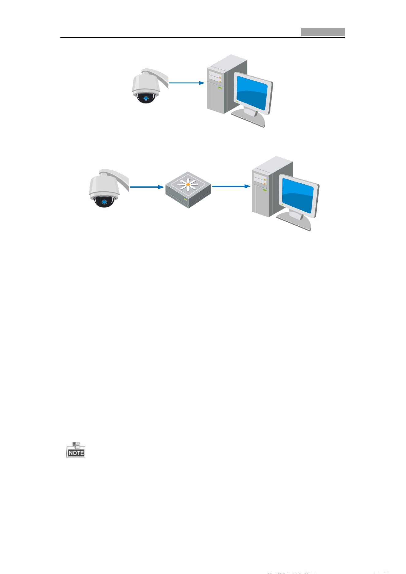
Refer to the Figure 2-2 to set the network speed dome over the LAN via a switch
or a router.
Network Speed Dome User Manual
13
Network Cable
Figure 2-1 Connecting Directly
Speed Dome
Network Cable
Switch or Router
PC
Network Cable
Figure 2-2 Connecting via a Switch or a Router
2.1.2 Activating the Speed Dome
Purpose:
You are required to activate the speed dome first before you can use the speed
dome.
Activation via Web Browser, Activation via SADP, and Activation via client software
are supported. In the following sections, activation via web browser and SADP will be
taken as examples. You may refer to the user manual of the speed dome for the
details of activation via client software.
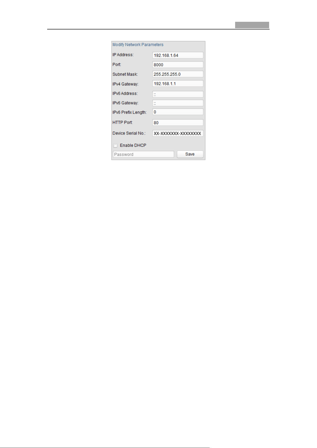
Activation via Web Browser
Steps:
1. Power on the speed dome, and connect the speed dome to the network.
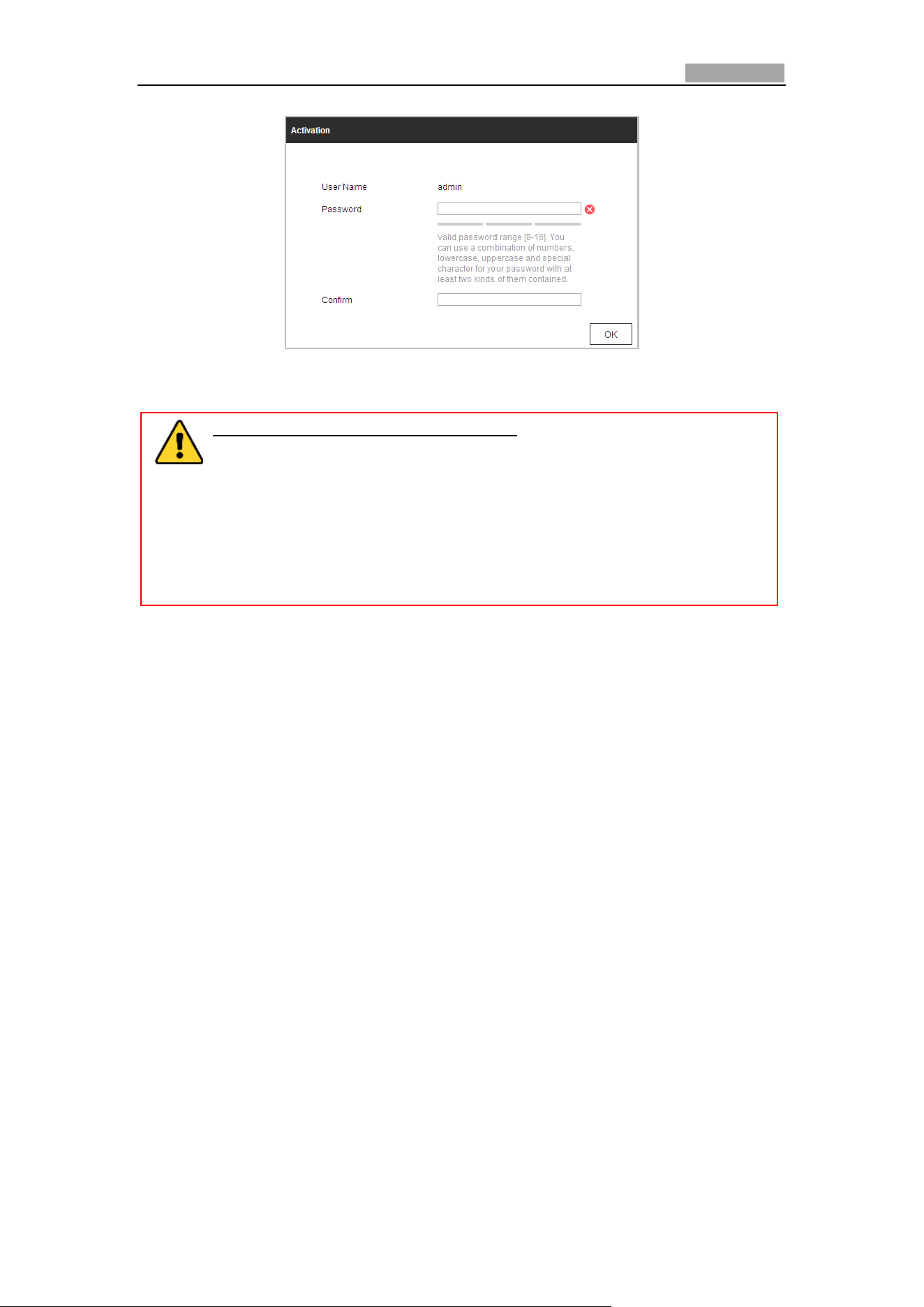
2. Input the IP address into the address bar of the web browser, and click Enter to
enter the activation interface.
The default IP address of the speed dome is 192.168.1.64.
Network Speed Dome User Manual
14
Figure 2-3 Activation Interface(Web)
3. Create a password and input the password into the password field.
STRONG PASSWORD RECOMMENDED– We highly recommend you
create a strong password of your own choosing (Using a minimum of 8
characters, including at least three of the following categories: upper
case letters, lower case letters, numbers, and special characters.) in
order to increase the security of your product. And we recommend you
reset your password regularly, especially in the high security system,
resetting the password monthly or weekly can better protect your
product.
4. Confirm the password.
5. Click OK to activate the speed dome and enter the live view interface.
Activation via SADP Software
SADP software is used for detecting the online device, activating the device, and
resetting the password.
Get the SADP software from the supplied disk or the official website, and install the
SADP according to the prompts. Follow the steps to activate the speed dome.
Steps:
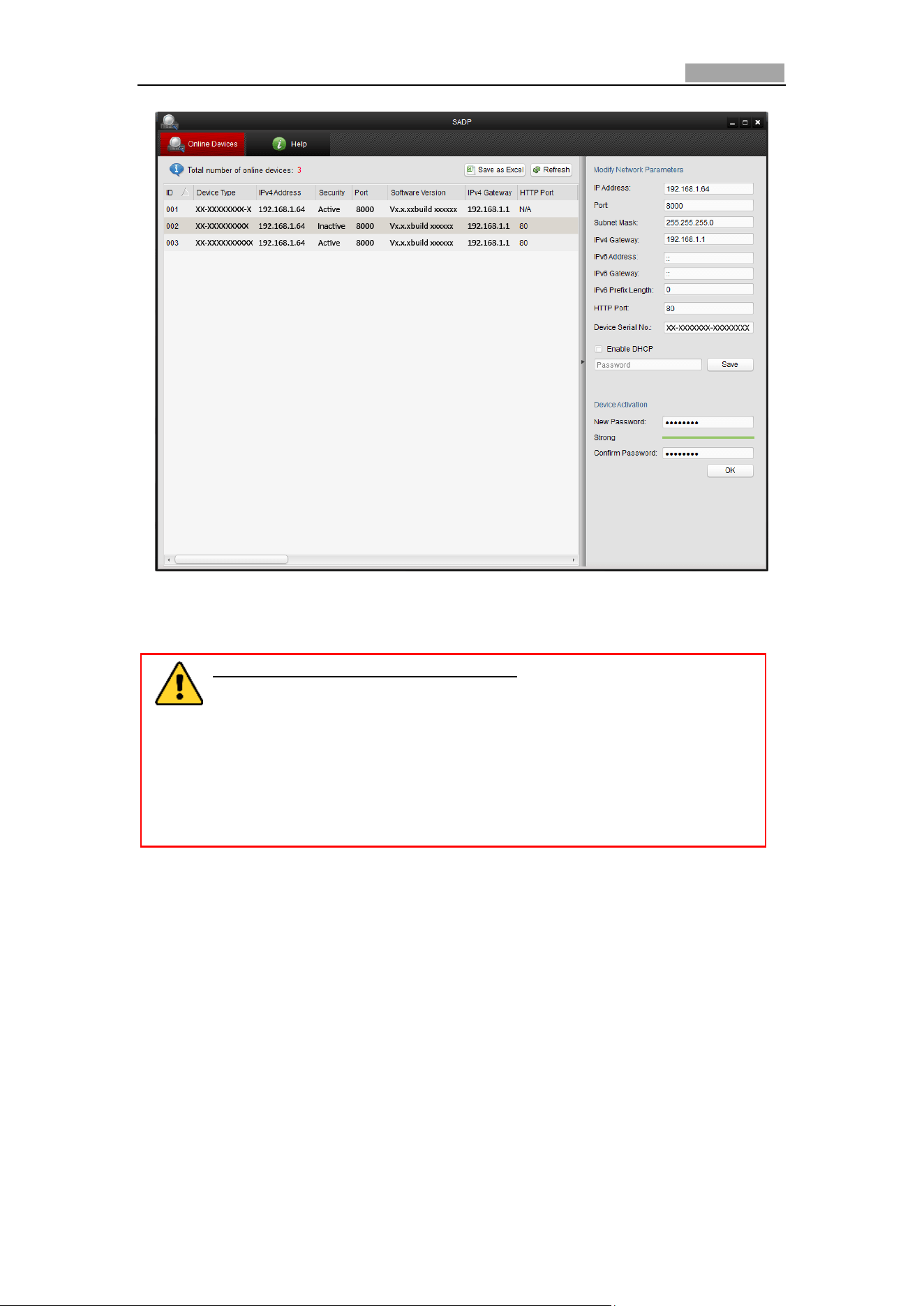
1. Run the SADP software to search the online devices.
2. Check the device status from the device list, and select an inactive device.
Network Speed Dome User Manual
15
Figure 2-4 SADP Interface
3. Create a password and input the password in the password field, and confirm the
password.
STRONG PASSWORD RECOMMENDED– We highly recommend you
create a strong password of your own choosing (Using a minimum of 8
characters, including at least three of the following categories: upper
case letters, lower case letters, numbers, and special characters.) in
order to increase the security of your product. And we recommend you
reset your password regularly, especially in the high security system,
resetting the password monthly or weekly can better protect your
product.
4. Click OK to save the password.
You can check whether the activation is completed on the popup window. If
activation failed, please make sure that the password meets the requirement
and then try again.
5. Change the device IP address to the same subnet with your computer by either
modifying the IP address manually or checking the checkbox of Enable DHCP.
Network Speed Dome User Manual
16
Figure 2-5 Modify the IP Address
6. Input the password and click the Save button to activate your IP address
modification.
Activation via Client Software
The client software is versatile video management software for multiple kinds of
devices.
Get the client software from the supplied disk or the official website, and install the
software according to the prompts. Follow the steps to activate the camera.
Steps:
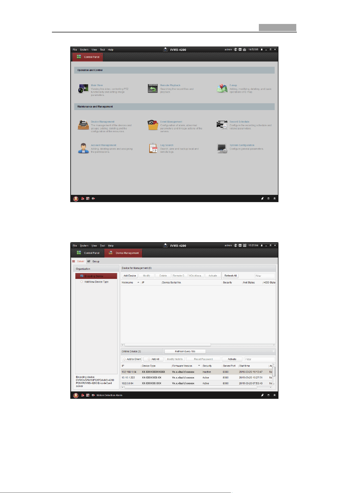
1. Run the client software and the control panel of the software pops up, as shown
in the figure below.
Network Speed Dome User Manual
17
Figure 2-6 Control Panel
2. Click the Device Management icon to enter the Device Management interface,
as shown in the figure below.
Figure 2-7 Device Management Interface
3. Check the device status from the device list, and select an inactive device.
4. Click the Activate button to pop up the Activation interface.
5. Create a password and input the password in the password field, and confirm the
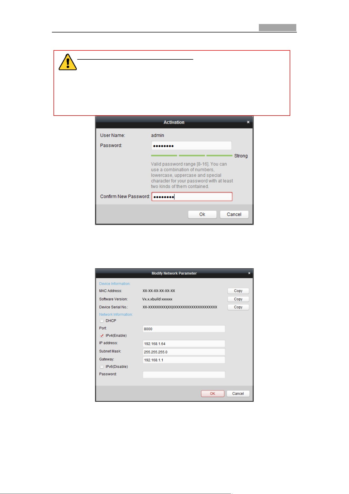
Network Speed Dome User Manual
18
password.
6. STRONG PASSWORD RECOMMENDED– We highly recommend you
create a strong password of your own choosing (Using a minimum of 8
characters, including at least three of the following categories: upper
case letters, lower case letters, numbers, and special characters.) in order
to increase the security of your product. And we recommend you reset
your password regularly, especially in the high security system, resetting
the password monthly or weekly can better protect your product.
Figure 2-8 Activation Interface
7. Click OK button to start activation.
8. Click the Modify Netinfo button to pop up the Network Parameter Modification
interface, as shown in the figure below.
Figure 2-9 Modifying the Network Parameters
9. Change the device IP address to the same subnet with your computer by either
modifying the IP address manually or checking the checkbox of Enable DHCP.
10. Input the password to activate your IP address modification.
Network Speed Dome User Manual
19
2.2 Setting the Network Speed Dome over the WAN
Purpose:
This section explains how to connect the network speed dome to the WAN with a
static IP or a dynamic IP.
2.2.1 Static IP Connection
Before you start:
Please apply a static IP from an ISP (Internet Service Provider). With the static IP
address, you can connect the network speed dome via a router or connect it to the
WAN directly.
Connecting the network speed dome via a router
Steps:
1. Connect the network speed dome to the router.
2. Assign a LAN IP address, the subnet mask and the gateway. Refer to Section 2.1.2
for detailed IP address configuration of the speed dome.
3. Save the static IP in the router.
4. Set port mapping, E.g., 80, 8000 and 554 ports. The steps for port mapping vary
depending on different routers. Please call the router manufacturer for assistance
with port mapping.
Refer to Appendix 2 for detailed information about port mapping.
5. Visit the network speed dome through a web browser or the client software over
the internet.
Speed Dome
Network
Cable
Router with Static IP
PC
Network
Cable
Network
Cable
Internet
Figure 2-10 Accessing the Speed Dome through Router with Static IP
Connecting the network speed dome with static IP directly
You can also save the static IP in the speed dome and directly connect it to the
internet without using a router. Refer to Section 2.1.2 for detailed IP address
configuration of the speed dome.
Network Speed Dome User Manual
20
Speed Dome
PC
Network
Cable
Network
Cable
Internet
Figure 2-11 Accessing the Speed Dome with Static IP Directly
2.2.2 Dynamic IP Connection
Before you start:
Please apply a dynamic IP from an ISP. With the dynamic IP address, you can connect
the network speed dome to a modem or a router.
Connecting the network speed dome via a router
Steps:
1. Connect the network speed dome to the router.
2. In the speed dome, assign a LAN IP address, the subnet mask and the gateway.
Refer to Section 2.1.2 for detailed LAN configuration.
3. In the router, set the PPPoE user name, password and confirm the password.
For your privacy and to better protect your system against security risks, we
strongly recommend the use of strong passwords for all functions and network
devices. The password should be something of your own choosing (Using a
minimum of 8 characters, including at least three of the following categories:
upper case letters, lower case letters, numbers, and special characters.) in
order to increase the security of your product.
Proper configuration of all passwords and other security settings is the
responsibility of the installer and/or end-user.
4. Set port mapping. E.g. 80, 8000 and 554 ports. The steps for port mapping vary
depending on different routers. Please call the router manufacturer for assistance
with port mapping.
Refer to Appendix 2 for detailed information about port mapping.
5. Apply a domain name from a domain name provider.
6. Configure the DDNS settings in the setting interface of the router.
7. Visit the speed dome via the applied domain name.
Network Speed Dome User Manual
21
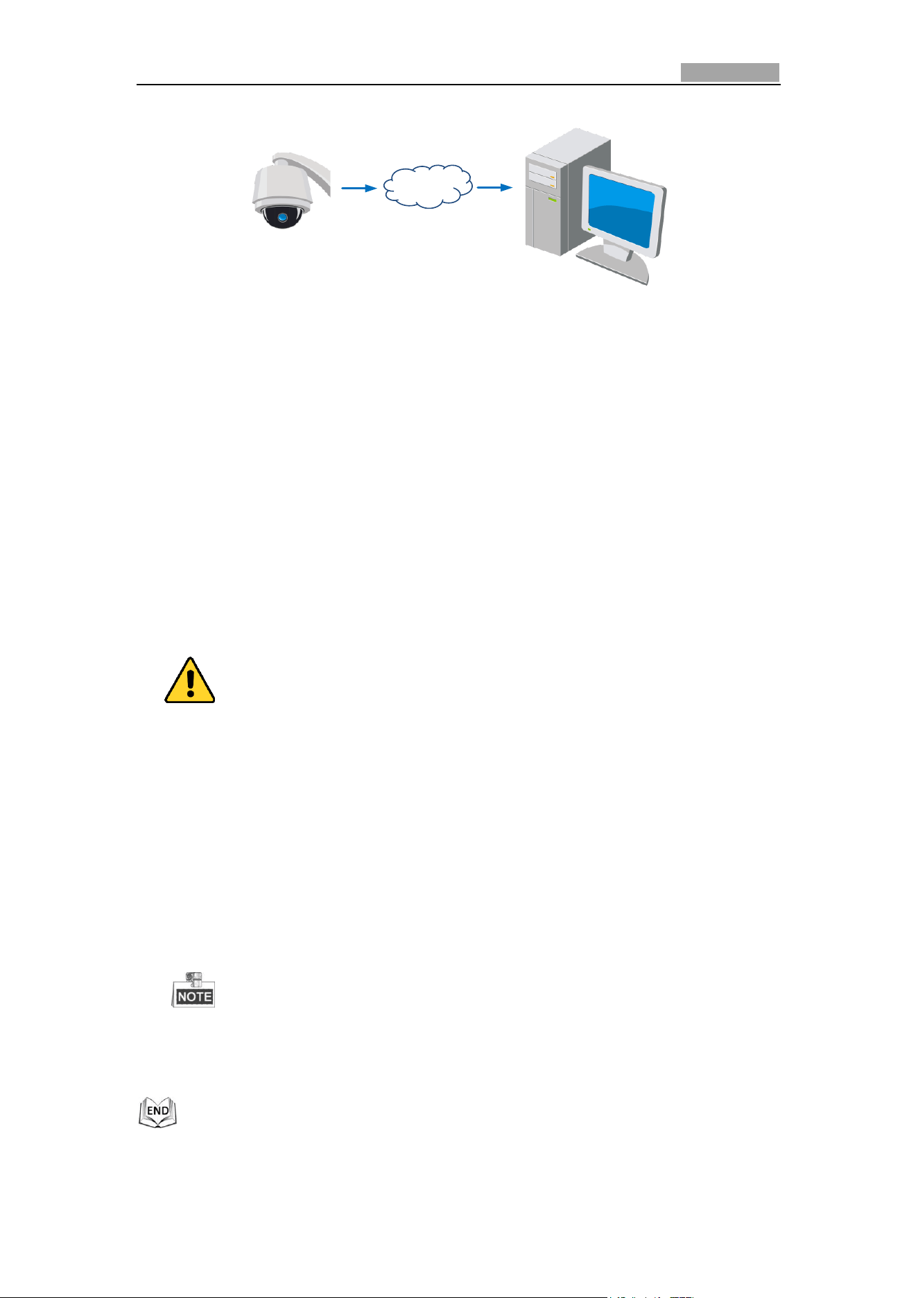
Connecting the network speed dome via a modem
Purpose:
This speed dome supports the PPPoE auto dial-up function. The speed dome gets a
public IP address by ADSL dial-up after the speed dome is connected to a modem.
You need to configure the PPPoE parameters of the network speed dome. Refer to
Section 0 Configuring PPPoE Settings for detailed configuration.
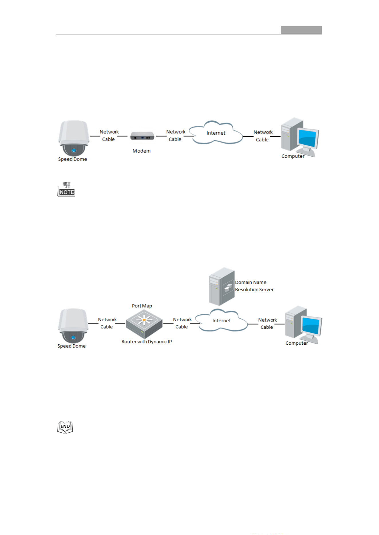
Figure 2-12 Accessing the Speed Dome with Dynamic IP
The obtained IP address is dynamically assigned via PPPoE, so the IP address
always changes after rebooting the speed dome. To solve the inconvenience of
the dynamic IP, you need to get a domain name from the DDNS provider (E.g.
DynDns.com). Please follow below steps for normal domain name resolution and
private domain name resolution to solve the problem.
Normal Domain Name Resolution
Figure 2-13 Normal Domain Name Resolution
Steps:
1. Apply a domain name from a domain name provider.
2. Configure the DDNS settings in the DDNS Settings interface of the network speed
dome. Refer to Section 0 Configuring DDNS Settings for detailed configuration.
3. Visit the speed dome via the applied domain name.
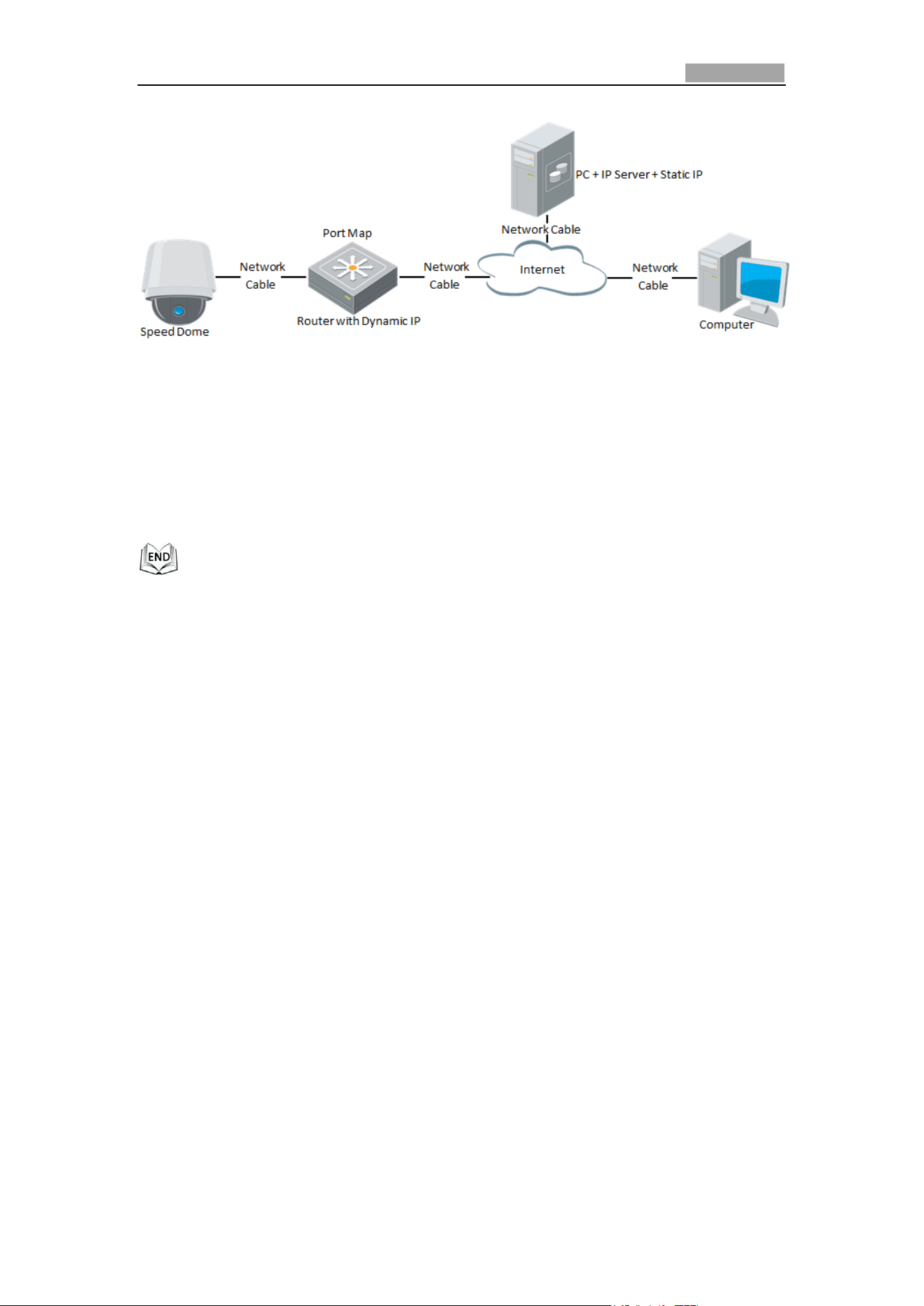
Private Domain Name Resolution
Network Speed Dome User Manual
22
Figure 2-14 Private Domain Name Resolution
Steps:
1. Install and run the IP Server software in a computer with a static IP.
2. Access the network speed dome through the LAN with a web browser or the
client software.
3. Enable DDNS and select IP Server as the protocol type. Refer to Section 0
Configuring DDNS Settings for detailed configuration.
User Manual of Network Speed Dome
23
Chapter 3 Access to the Network
Speed Dome
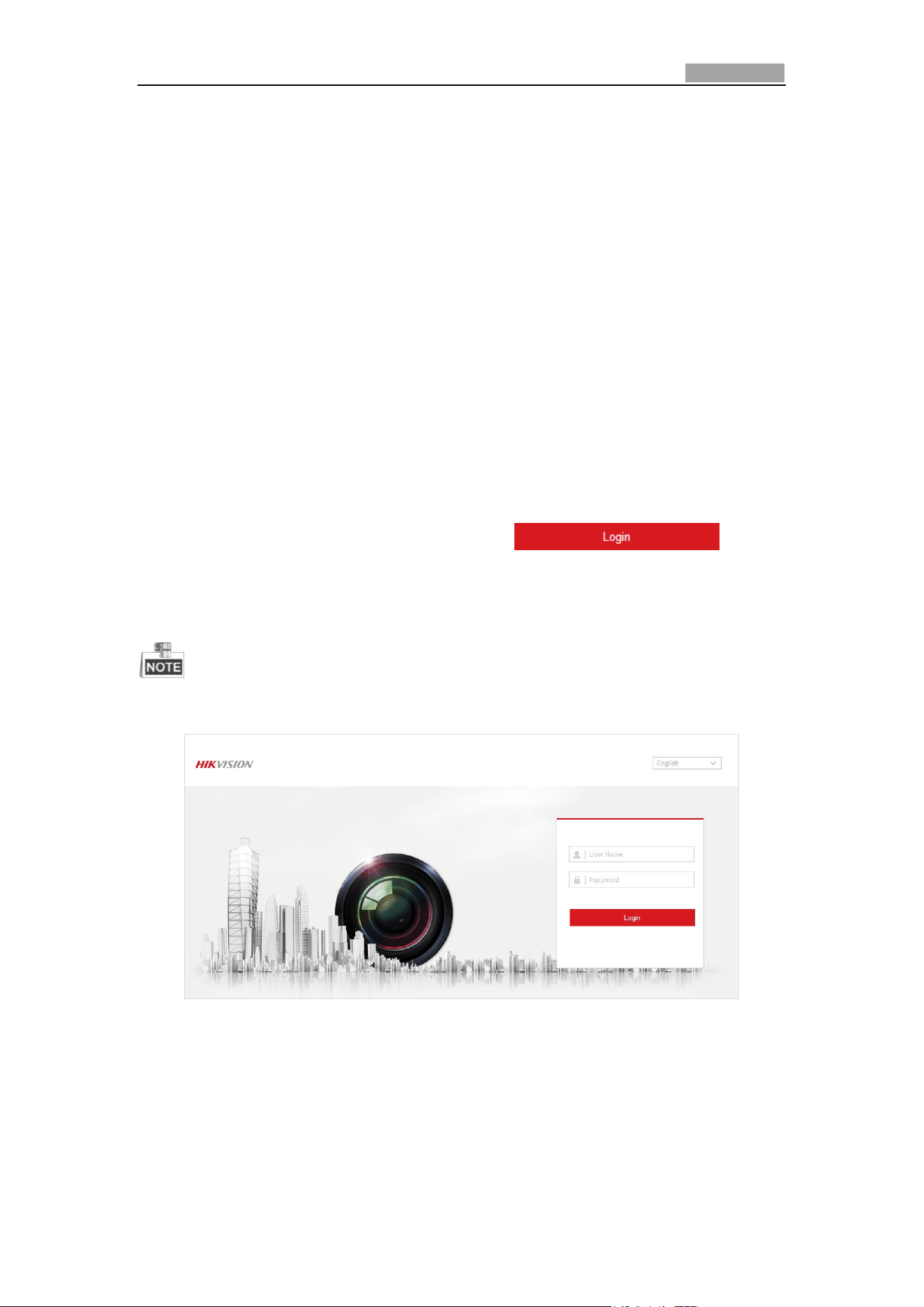
3.1 Accessing by Web Browsers
Steps:
1. Open the web browser.
2. In the address field, input the IP address of the network speed dome, e.g.,
192.168.1.64 and press the Enter key to enter the login interface.
3. Activate the speed dome for the first time using, refer to the section 2.1.2
Activating the Speed Dome.
4. Select English as the interface language on the top-right of login interface.
5. Input the user name and password and click .
The admin user should configure the device accounts and user/operator
permissions properly. Delete the unnecessary accounts and user/operator
permissions.
The device IP address gets locked if the admin user performs 7 failed password
attempts (5 attempts for the user/operator).
Figure 3-1 Login Interface
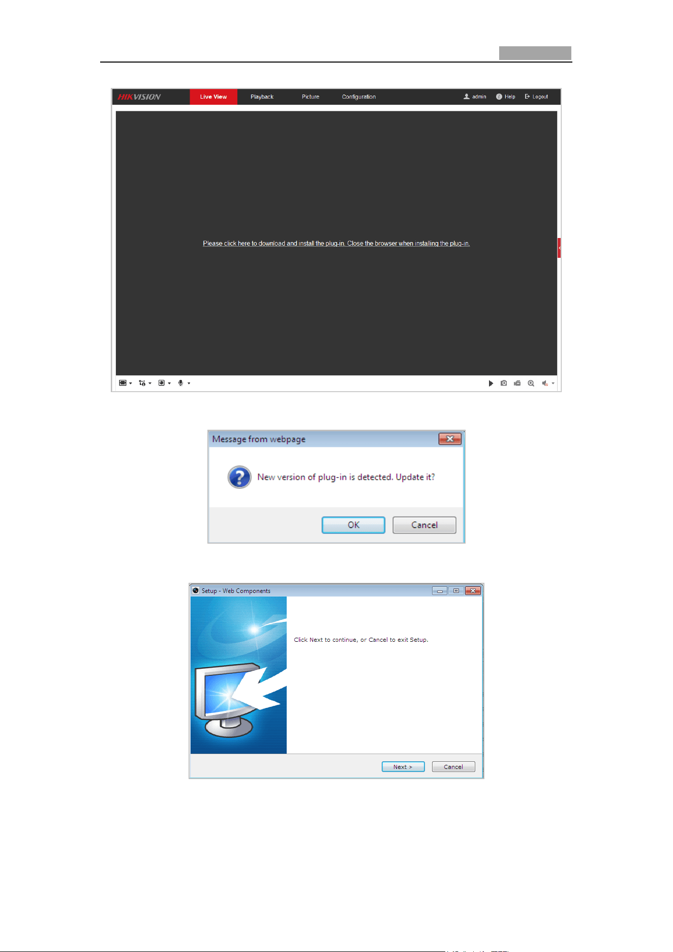
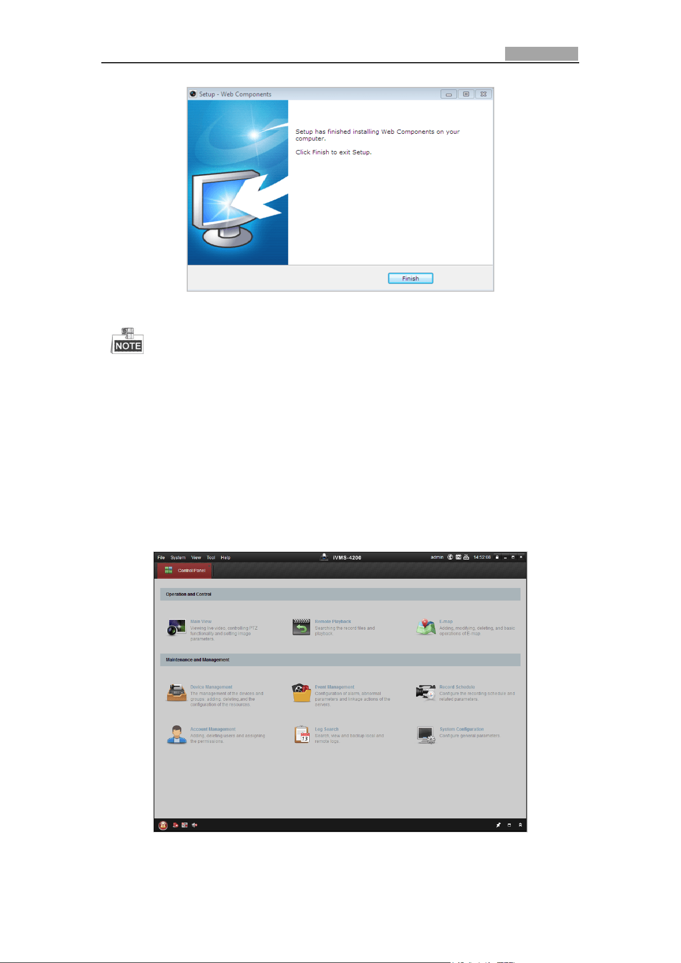
6. Install the plug-in before viewing the live video and operating the speed dome.
Please follow the installation prompts to install the plug-in.
Network Speed Dome User Manual
24
Figure 3-2 Download and Install Plug-in
Figure 3-3 Install Plug-in (1)
Figure 3-4 Install Plug-in (2)
Network Speed Dome User Manual
25
Figure 3-5 Install Plug-in (3)
You may have to close the web browser to install the plug-in. Please reopen the
web browser and log in again after installing the plug-in.
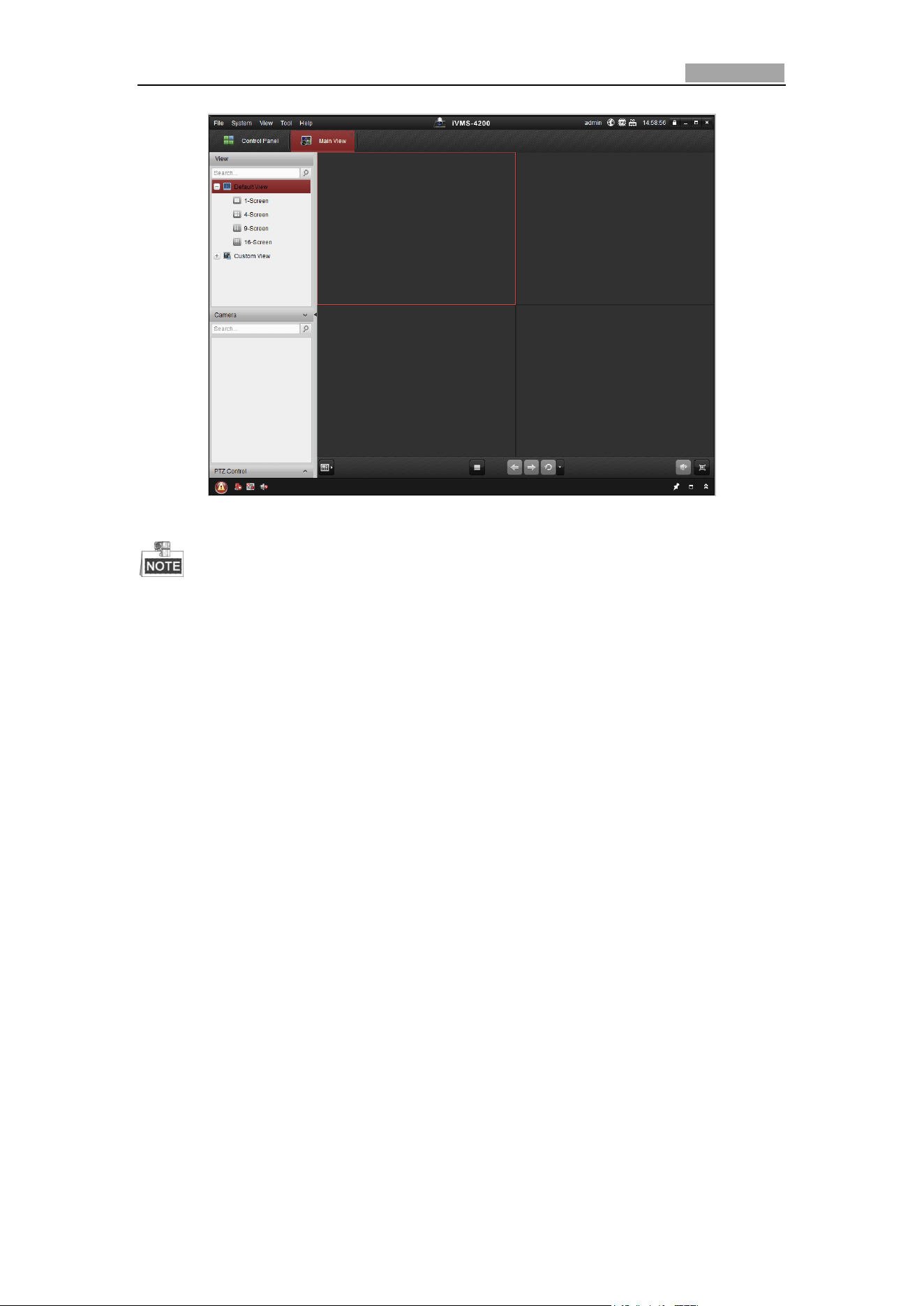
3.2 Accessing by Client Software
The product CD contains the client software. You can view the live video and manage
the speed dome with the client software.
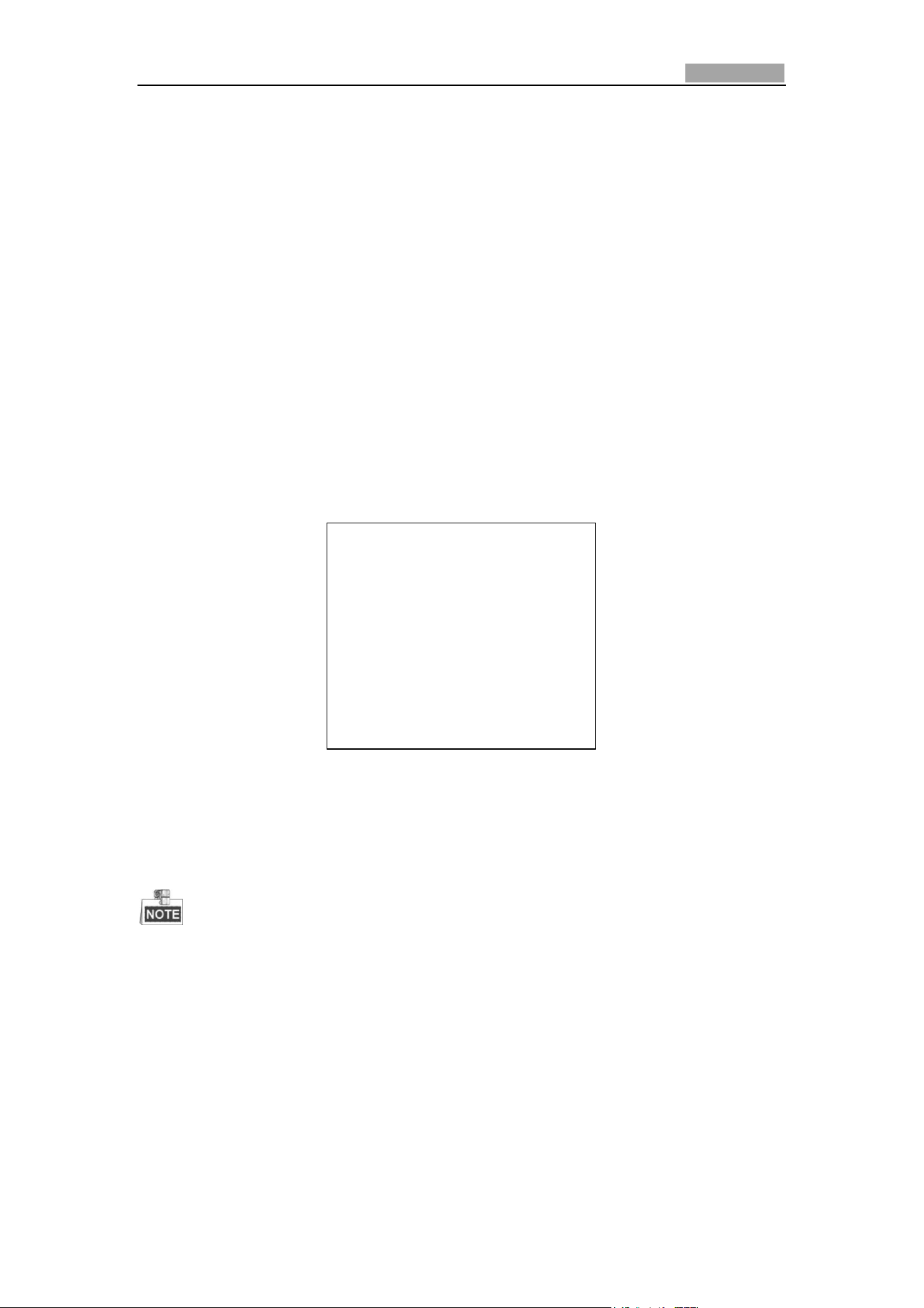
Follow the installation prompts to install the client software and WinPcap. The
configuration interface and live view interface of client software are shown below.
Figure 3-6 iVMS-4200 Control Panel
Network Speed Dome User Manual
26
Figure 3-7 iVMS-4200 Live View Interface
If you use third party VMS software, please contact technical support of our
branch for camera firmware.
For detailed information about client software of our company, please refer to
the user manual of the software. This manual mainly introduces accessing to the
network speed dome by web browser.
Network Speed Dome User Manual
27
Chapter 4 Basic Operations
In this and the following chapters, operation of the speed dome by the web browser
will be taken as an example.
4.1 Power-up Action
After the power is applied, the speed dome will perform self-test actions. It begins
with lens actions and then pan and tilt movement. After the power-up self-test
actions, the information as shown in Figure 4-1 will be displayed on screen for 40
seconds.
The System Information displayed on the screen includes the dome model, address,
protocol, version and other information. The COMMUNICATION refers to the baud
rate, parity, data bit and stop bit of the dome. e.g., “2400, N, 8, 1” indicates the dome
is configured with the baud rate of 2400, no parity, 8 data bits and 1 stop bit.
Model XX-XXXXXX-X
Address 0
Communication 0000,0,0,0
Software Version Vx.x.x
Camera Version Vx.xx
Language English
Figure 4-1 Power-up Information
4.2 Configuring Local Parameters
The local configuration refers to the parameters of the live view and other
operations using the web browser.
Steps:
1. Enter the Local Configuration interface:
Configuration > Local
Network Speed Dome User Manual
28
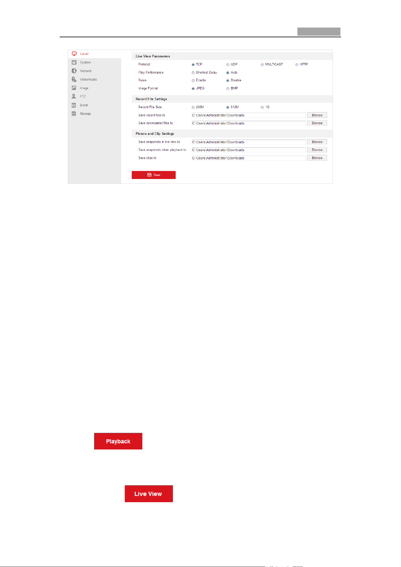
Figure 4-2 Local Configuration Interface
2. Configure the following settings:
Live View Parameters: Set the protocol type, stream type, image size and live
view performance.
Protocol Type: TCP, UDP, MULTICAST and HTTP are selectable.
TCP: Ensures complete delivery of streaming data and better video quality, yet
the real-time transmission will be affected.
UDP: Provides real-time audio and video streams.
HTTP: Allows the same quality as of TCP without setting specific ports for
streaming under some network environments.
MULTICAST: It’s recommended to select the protocol type to Multicast when
using the Multicast function. For other information about Multicast, refer to
Section 0 Configuring TCP/IP Settings.
Live View Performance: Set the live view performance to Shortest Delay or
Auto.
Rules: You can enable or disable the rules of dynamic analysis for events here.
Image Format: The captured pictures can be saved as different format. JPEG
and BMP are available.
Record File Settings: Set the saving path of the video files.
Record File Size: Select the packed size of manually recorded and downloaded
video files. The size can be set to 256M, 512M or 1G.
Save record files to: Set the saving path for the manually recorded video files.
Save downloaded files to: Set the saving path for the downloaded video files
in interface.
Picture and Clip Settings: Set the saving paths of the captured pictures and
clipped video files.
Save snapshots in live view to: Set the saving path of the manually captured
pictures in interface.
Save snapshots when playback to: Set the saving path of the captured
Network Speed Dome User Manual
29
pictures in interface.
Save clips to: Set the saving path of the clipped video files in
interface.
You can click to change the directory for saving video files, clips
and pictures.
3. Click to save the settings.
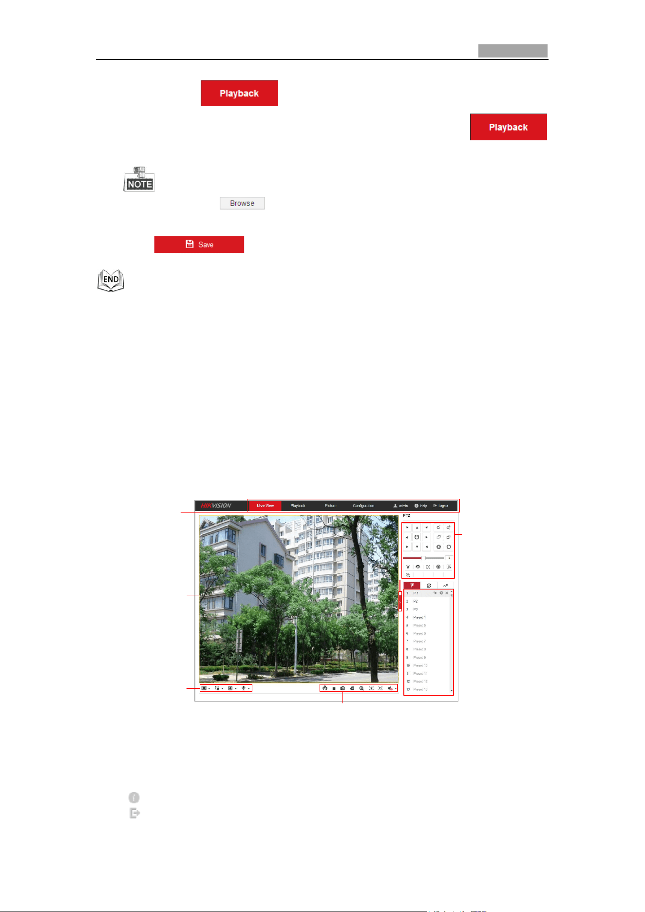
4.3 Live View Page
Purpose:
The live video page allows you to view live video, capture images, realize PTZ control,
set/call presets and configure video parameters.
Log in the network speed dome to enter the live view page, or you can click Live
View on the menu bar of the main page to enter the live view page.
Descriptions of the live view page:
Menu Bar
Live View
Parameters
Live View Window
Toolbar
Show or hide PTZ
control panel
PTZ Control
Preset/Patrol/Pattern
Figure 4-3 Live View Page
Menu Bar:
Click each tab to enter Live View, Playback, Picture, and Configuration page
respectively.
Click to display the help file of the speed dome.
Click to logout the system.
Network Speed Dome User Manual
30
Live View Window:
Display the live video.
Toolbar:
Operations on the live view page, e.g., live view, capture, record, audio on/off,
regional exposure, regional focus, etc.
PTZ Control:
Panning, tilting, focusing and zooming actions of the speed dome. The lighter, wiper,
one-touch focus and lens initialization control.
Preset/patrol/pattern:
Set and call the preset/patrol/pattern for the speed dome.
Live View Parameters:
Configure the image size, stream type, plug-in type, and two-way audio of the live
video.
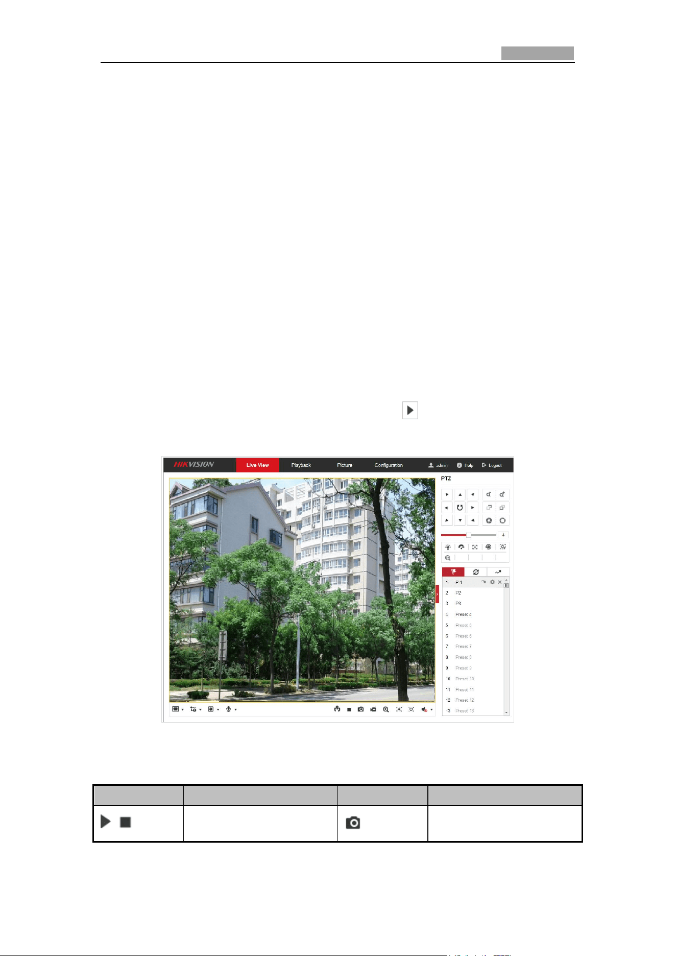
4.4 Starting Live View
In the live view window as shown in Figure 4-4, click on the toolbar to start the
live view of the speed dome.
Figure 4-4 Start Live View
Table 4-1 Descriptions of the Toolbar
Icon
Description
Icon
Description
/
Start/Stop Live view.
Manually capture the pictures.
Network Speed Dome User Manual
31
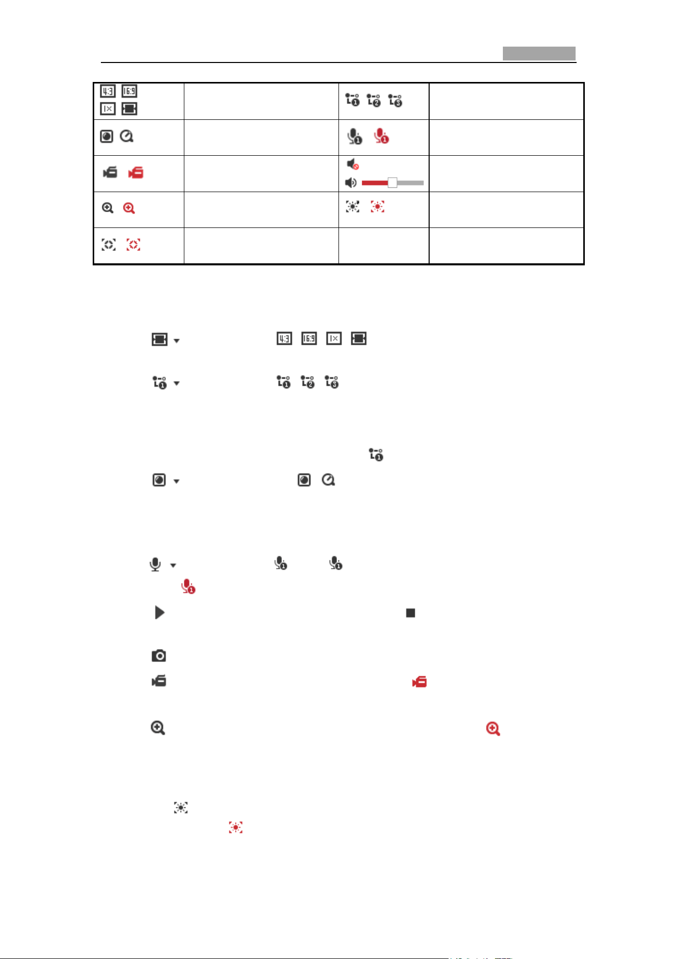
/ /
/
Display in 4:3/16:9/original/
Self-adaptive window size.
/ /
Live view with the
main/sub/third stream.
/
Play via webcomponents/
quick time.
/
Start/Stop Two-way Audio.
/
Manual start/stop recording.
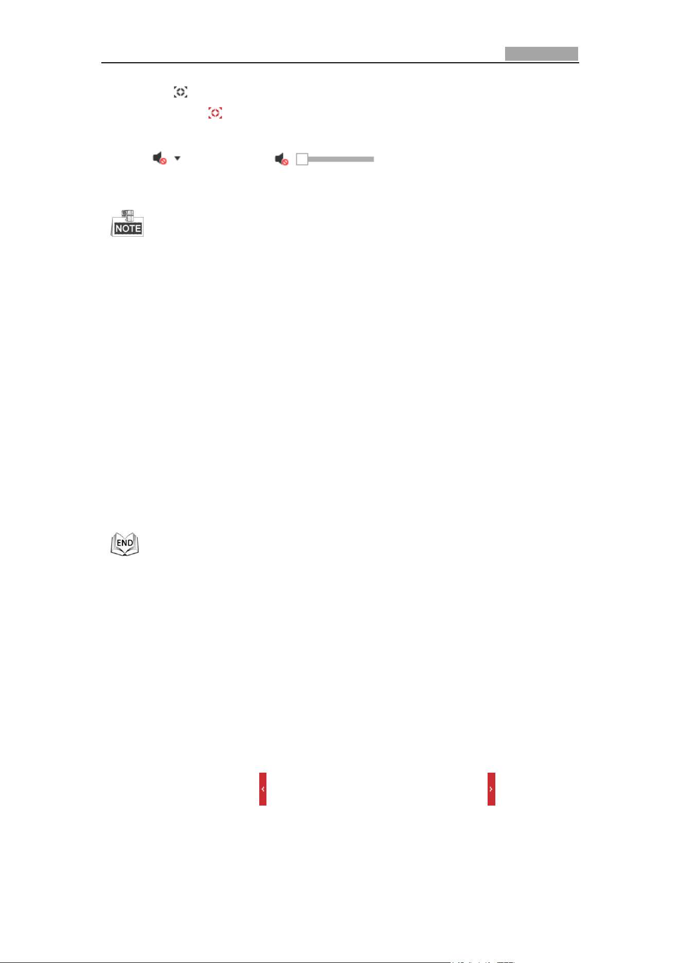
/
Mute/Audio on and adjust
volume
/
Start/stop digital zoom.
/
Enable/Disable Regional
Exposure
/
Enable / Disable Regional
Focus
Double-click on the live video to switch the current live view into full-screen or
return to normal mode from the full-screen.
Click to select from and display live video in 4:3/16:9/
original/self-adaptive window size.
Click to select from and display live video with the main/
sub/third stream. The main stream is with a relatively high resolution and needs
much bandwidth. The sub-stream is with a low resolution and needs less
bandwidth. The resolution of third stream is between that of main stream and sub
stream. The default setting of stream type is .
Click to select between and play the live video via player
Webcomponents or Quick Time. The live video is played via webcomponents by
default, and other types of players are supported for the browser, such as MJPEG,
and VLC. You are required to download and install the player to play the live video.
Click and it displays . Click to enable two-way audio and the icon
turns into . Click the icon again to stop two-way audio.
Click to start live view and the icon turns into . Click the icon again to stop
live view.
Click to capture the picture.
Click to start recording and the icon turns into . Click the icon again to
stop recording.
Click to enable digital zoom function and the icon turns into . Then
click-and-drag the mouse towards low right direction to draw a rectangle on the
image as the desired zoom. After viewing it you can click any place of the picture
to get back to normal picture.
Click the on the toolbar to enter the regional exposure operation mode and
the icon turns into . Then click-and-drag the mouse to draw a rectangle on the
image as the desired exposure region.
Network Speed Dome User Manual
32
Click the on the toolbar to enter the regional focus operation mode and the
icon turns into . Then click-and-drag the mouse to draw a rectangle on the
image as the desired focus region.
Click to display the . Drag the slider to adjust the
volumn.
Not all the speed dome models support the above functions. Please take the
browser interface of the actual product as standard.
Before enabling the two-way audio or recording with audio functions, please set
the Stream Type to Video & Audio referring to Section 6.4.1 Configuring Video
Settings.
Please refer to the following sections for more information:
Configuring remote recording in Section 5.1 Storage Settings
Before you start:
To configure record settings, please make sure that you have the network storage
device within the network or the storage card has been inserted in the corresponding
card slot. Refer to the installation guide for the location of the storage card slot.
Configuring Recording Schedule.
Setting the image quality of the live video in Section 4.2 Configuring Local
Parameters and Section 6.2.1 Configuring Video Settings.
Setting the OSD text on live video in Section 6.3.2 Configuring OSD Settings.
4.5 Operating PTZ Control
Purpose:
In the live view interface, you can use the PTZ control buttons to control panning,
tilting and zooming.
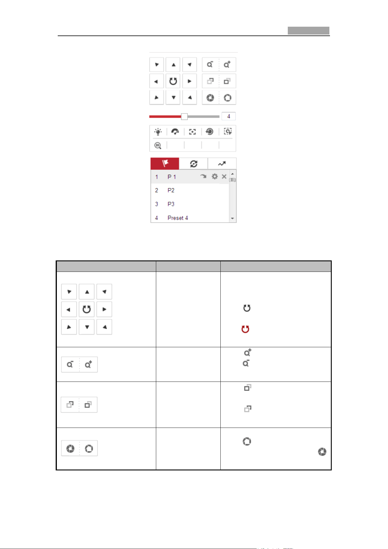
4.5.1 PTZ Control Panel
On the live view page, click to show the PTZ control panel or click to hide it.
Click the direction buttons to control the pan/tilt movements.
Click the zoom/iris/focus buttons to realize lens control.
Network Speed Dome User Manual
33
Figure 4-5 PTZ Control Panel
Table 4-2 Descriptions of PTZ Control Panel
Button
Name
Description
PTZ Control Panel
Hold and press the direction
button to pan/tilt the speed
dome.
Click and the speed dome
keeps panning, the icon turns
into . Click the icon again to
stop the speed dome.
Zoom out/in
Click , the lens zooms in,
click , and the lens zooms
out.
Focus near/far
Click , the lens focus far and
the items far away gets clear.
Click , the lens focus near
and the items nearby gets clear.
Iris close/open
When the image is too dark,
click to open the iris. When
the image is too bright, click
to close the iris.
Network Speed Dome User Manual
34
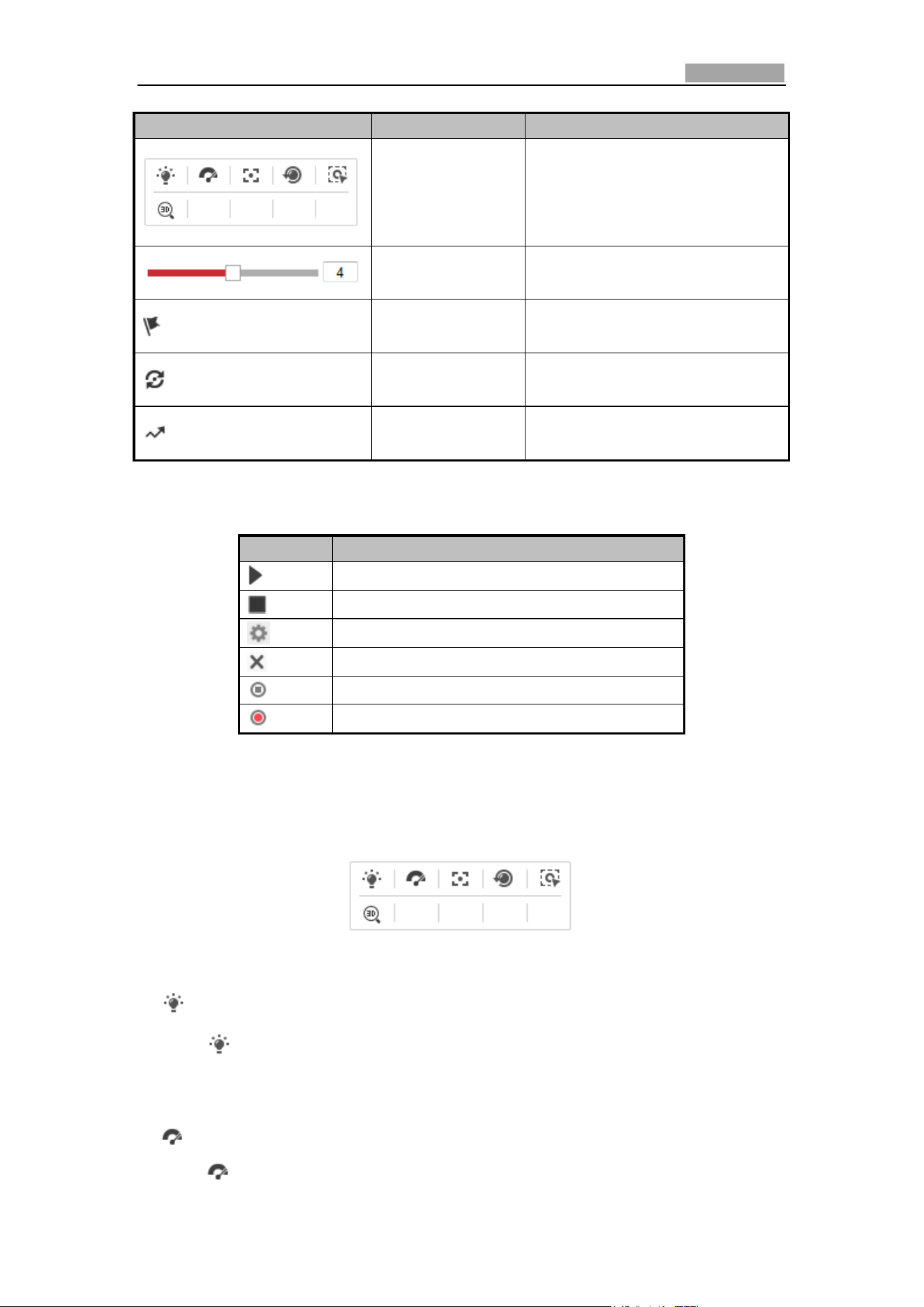
Button
Name
Description
Auxiliary
Functions
The auxiliary functions include
light, wiper, auxiliary focus, lens
initialization, manual tracking,
and 3D positioning.
Speed
Adjustment
Adjust speed of pan/tilt
movements.
Preset
Refer to 4.5.3 for detailed
information of setting preset.
Patrol
Refer to 4.5.4 for detailed
information of setting patrol.
Pattern
Refer to 4.5.6 for detailed
information of setting pattern.
Buttons on the Preset/Patrol/Patterns interface:
Buttons
Description
Start the selected patrol/pattern.
Stop current patrol/pattern.
Set the selected preset/patrol.
Delete the selected preset/patrol/pattern.
Start recording a pattern.
Stop recording the pattern.
4.5.2 Auxiliary Functions
The Auxiliary functions panel is shown in the figure below:
Figure 4-6 Auxiliary Functions
Light
Click to enable/disable the light supplement of the speed dome. This
function is reserved.
Wiper
Click to move the wiper once.

Network Speed Dome User Manual
35
Auxiliary Focus
The auxiliary focus function is reserved.
Manual Tracking
Before you start:
Please enter the Smart Tracking settings interface and enable smart tracking first.
Configuration > PTZ > Smart Tracking
Steps:
1. Click on the toolbar of live view interface.
2. Click a moving object in the live video.
The speed dome will track the object automatically.
3D Positioning
Steps:
1. Click on the toolbar of live view interface.
2. Operate the 3D positioning function:
Left click a position of the live video. The corresponding position will be moved
to the center of the live video.
Hold down the left mouse button and drag the mouse to the lower right on the
live video. The corresponding position will be moved to the center of the live
video and zoomed in.
Hold down the left mouse button and drag the mouse to the upper left on the
live video. The corresponding position will be moved to the center of the live
video and zoomed out.
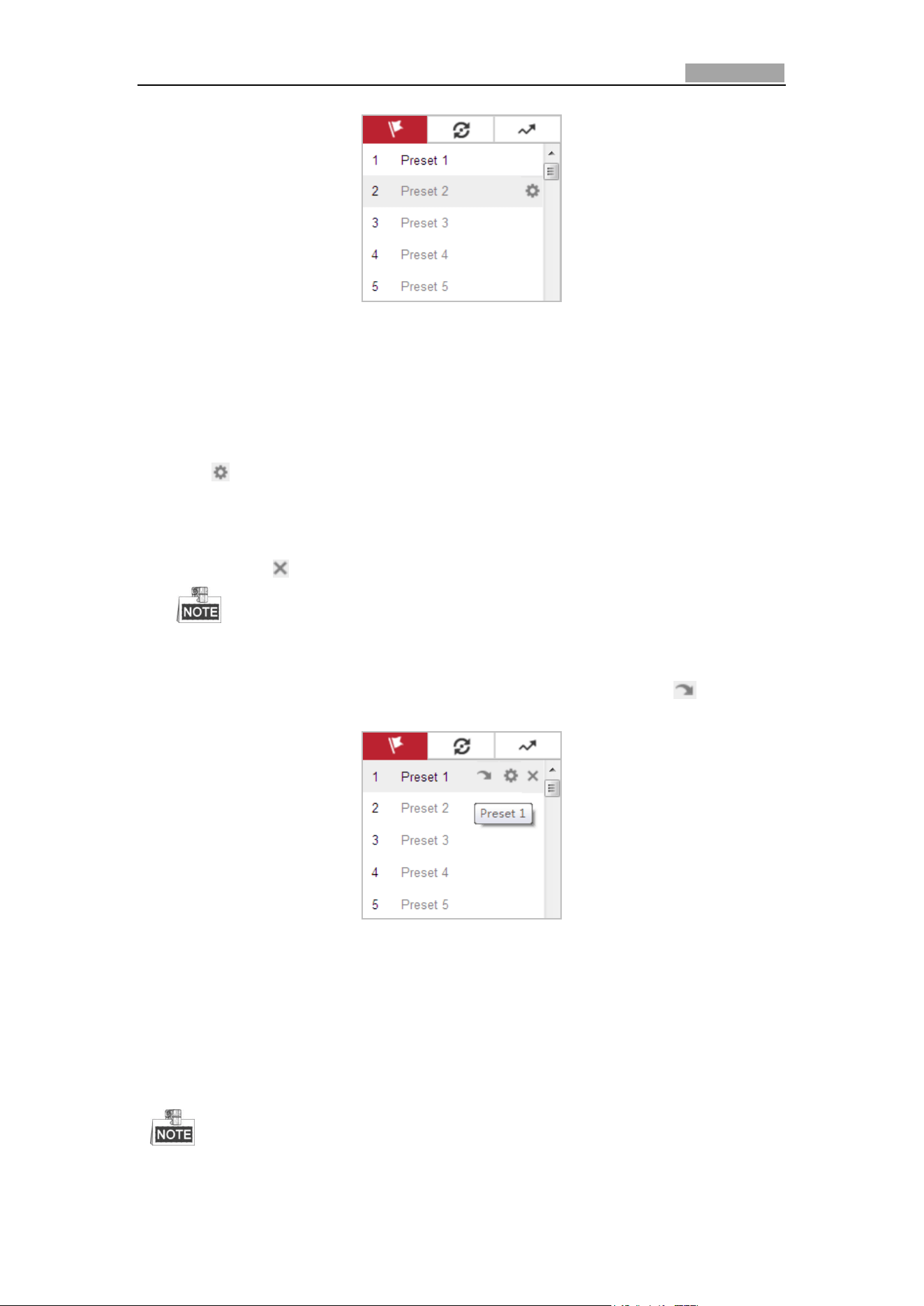
4.5.3 Setting/Calling a Preset
Purpose:
A preset is a predefined image position. For the defined preset, you can click the
calling button to quickly view the desired image position.
Setting a Preset:
Steps:
1. In the PTZ control panel, select a preset number from the preset list.
Network Speed Dome User Manual
36
Figure 4-7 Setting a Preset
2. Use the PTZ control buttons to move the lens to the desired position.
Pan the speed dome to the right or left.
Tilt the speed dome up or down.
Zoom in or out.
Refocus the lens.
3. Click to finish the setting of the current preset.
4. Edit a preset name by double clicking on the default name such as preset 1. (The
pre-defined presets are named already and not configurable. Please refer to the
user manual for detailed function description.)
5. You can click to delete the preset.
You can configure up to 300 presets.
Calling a Preset:
In the PTZ control panel, select a defined preset from the list and click to call the
preset.
Figure 4-8 Calling a Preset
For convenient preset selection, refer to the following steps to navigate to the preset
you want.
Steps:
1. Select any preset from the list.
2. Click the preset number you need on the keyboard.
The following presets are predefined with special commands. You can only call
Network Speed Dome User Manual
37
them but not configure them. For instance, preset 99 is the “Start auto scan”. If
you call the preset 99, the speed dome starts auto scan function.
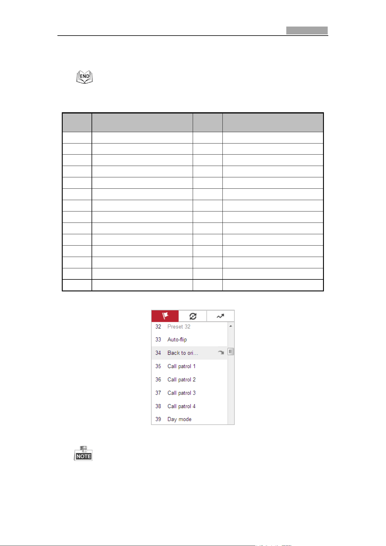
Table 4-3 Special Presets
Preset
Function
Preset
Function
33
Auto flip
92
Start to set limit stops
34
Back to initial position
93
Set limit stops manually
35
Call patrol 1
94
Remote reboot
36
Call patrol 2
95
Call OSD menu
37
Call patrol 3
96
Stop a scan
38
Call patrol 4
97
Start random scan
39
Day mode (IR cut filter in)
98
Start frame scan
40
Night mode (IR cut filter out)
99
Start auto scan
41
Call pattern 1
100
Start tilt scan
42
Call pattern 2
101
Start panorama scan
43
Call pattern 3
102
Call patrol 5
44
Call pattern 4
103
Call patrol 6
45
One-touch Patrol
104
Call patrol 7
90
Wiper
105
Call patrol 8
Figure 4-9 Special Preset
You may need to use the OSD (On Screen Display) menu when controlling
the speed dome remotely. To display the OSD menu on the live view screen,
you can call the preset number 95.
Network Speed Dome User Manual
38
4.5.4 Setting/Calling a Patrol
Purpose:
A patrol is a memorized series of preset function. It can be configured and called on
the patrol settings interface. There are up to 8 patrols for customizing. A patrol can
be configured with 32 presets.
Before you start:
Please make sure that the presets you want to add into a patrol have been defined.
Setting a Patrol:
Steps:
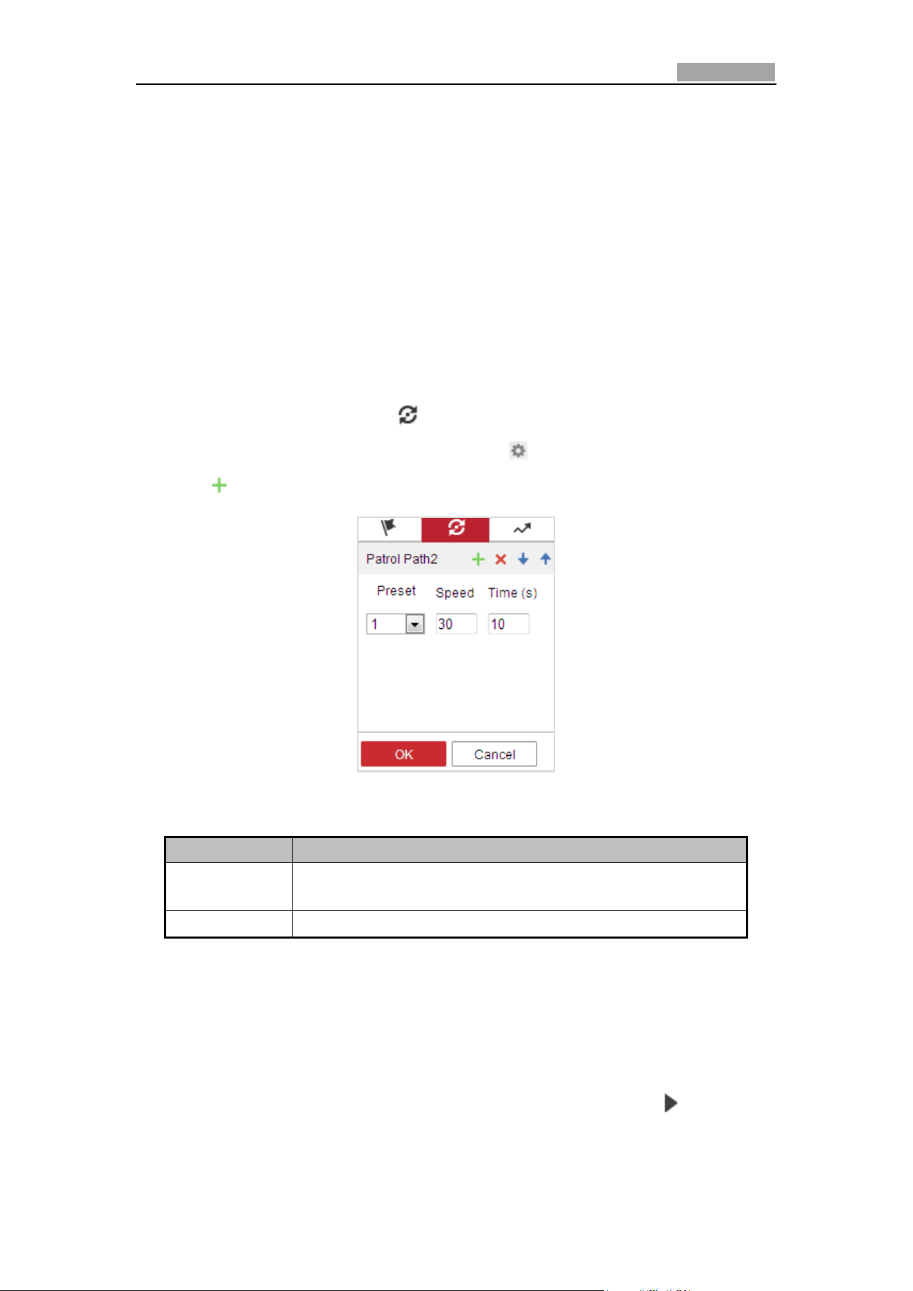
1. In the PTZ control panel, click to enter the patrol settings interface.
2. Select a patrol number from the list and click .
3. Click to enter the adding interface of preset, as shown in Figure 4-10.
Figure 4-10 Adding Presets
4. Configure the preset number, patrol time and patrol speed.
Name
Description
Patrol Time
It is the duration staying on one patrol point. The speed
dome moves to another patrol point after the patrol time.
Patrol Speed
It is the speed of moving from one preset to another.
5. Click OK to save a preset into the patrol.
6. Repeat the steps from 3 to 5 to add more presets.
7. Click OK to save all the patrol settings.
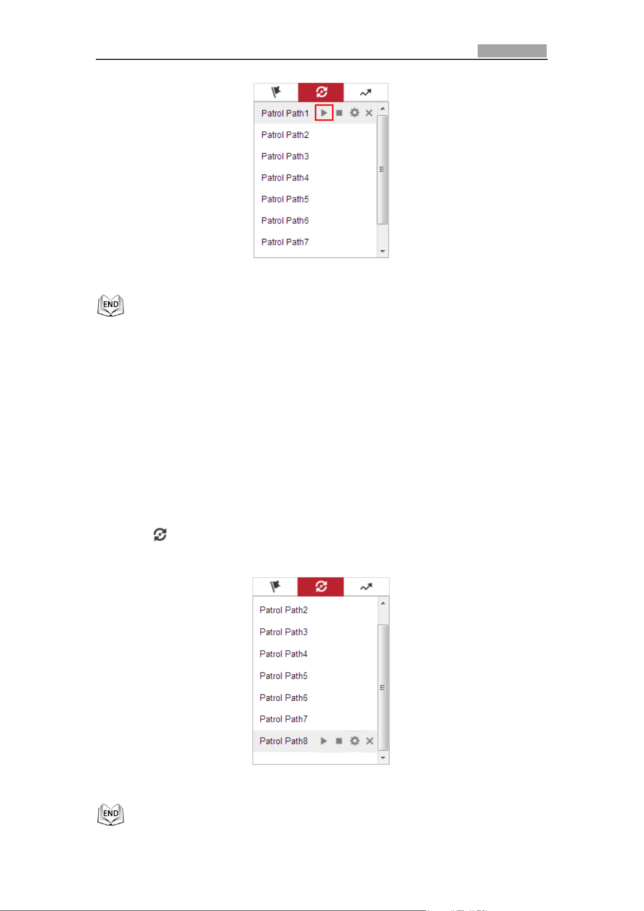
Calling a Patrol:
In the PTZ control panel, select a defined patrol from the list and click to call the
patrol, as shown in Figure 4-11.
Network Speed Dome User Manual
39
Figure 4-11 Calling a Patrol
4.5.5 One-touch Patrol
Purpose:
One-touch patrol is an automatically created patrol. The system automatically add
preset No.1 to No.32 to the patrol path 8. You can call the one-touch patrol and the
speed dome moves as the patrol path 8 automatically.
Steps:
1. Set preset No.1 to No.32. Refer to 4.5.3 Setting/Calling a Preset for detailed
information of setting preset.
2. Call preset No. 45, and the speed dome moves as patrol path 8.
3. Click to enter the patrol settings interface and start/stop one-touch patrol,
edit the patrol time and the speed.
Figure 4-12 Patrol Path 8
Network Speed Dome User Manual
40
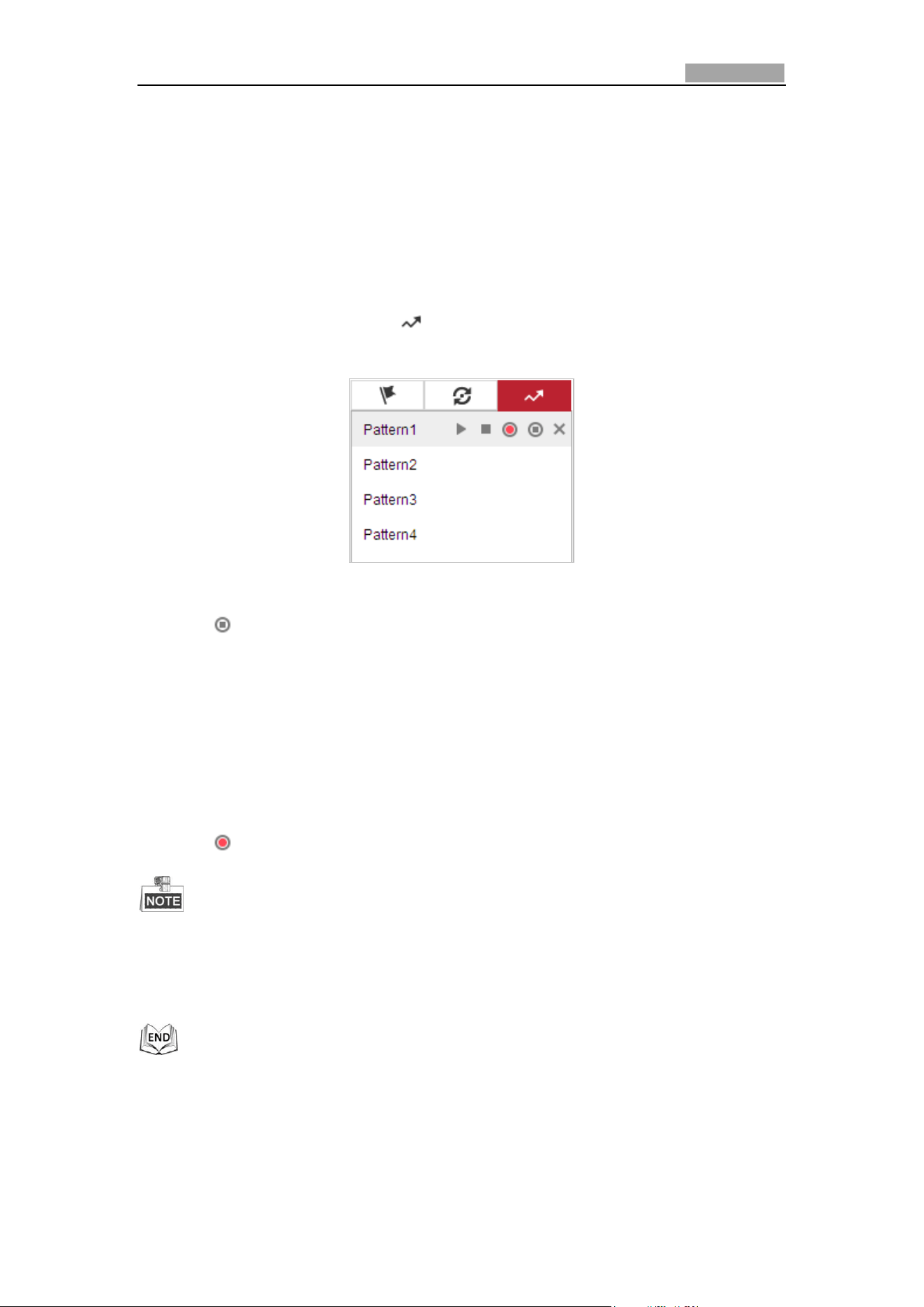
4.5.6 Setting/Calling a Pattern
Purpose:
A pattern is a memorized series of pan, tilt, zoom, and preset functions. It can be
called on the pattern settings interface. There are up to 4 patterns for customizing.
Setting a Pattern:
Steps:
1. In the PTZ control panel, click to enter the pattern settings interface.
2. Select a pattern number from the list as shown in Figure 4-13.
Figure 4-13 Patterns Settings Interface
3. Click to enable recording the panning, tilting and zooming actions.
4. Use the PTZ control buttons to move the lens to the desired position after the
information of Program Pattern Remaining Memory (%) is displayed on the
screen.
Pan the speed dome to the right or left.
Tilt the speed dome up or down.
Zoom in or out.
Refocus the lens.
5. Click to save all the pattern settings.
These 4 patterns can be operated separately and with no priority level.
When configuring and calling the pattern, proportional pan is valid; the limit
stops and auto flip will be invalid; and the 3D positioning operation is not
supported.
Network Speed Dome User Manual
41
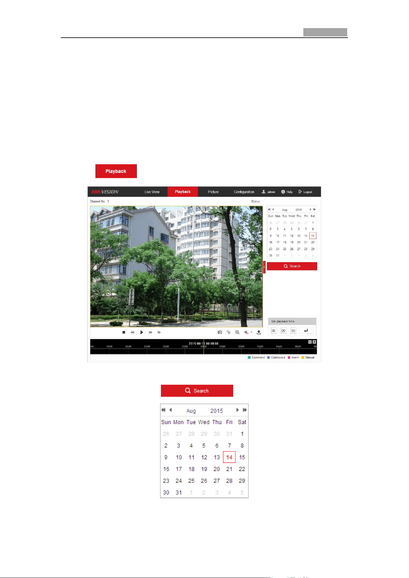
4.6 Playback
Purpose:
This section explains how to view the remotely recorded video files stored in the
microSD card or network disks.
Play Back Video Files
Steps:
1. Click on the menu bar to enter playback interface.
Figure 4-14 Playback Interface
2. Select the date and click .
Figure 4-15 Search Video
Network Speed Dome User Manual
42
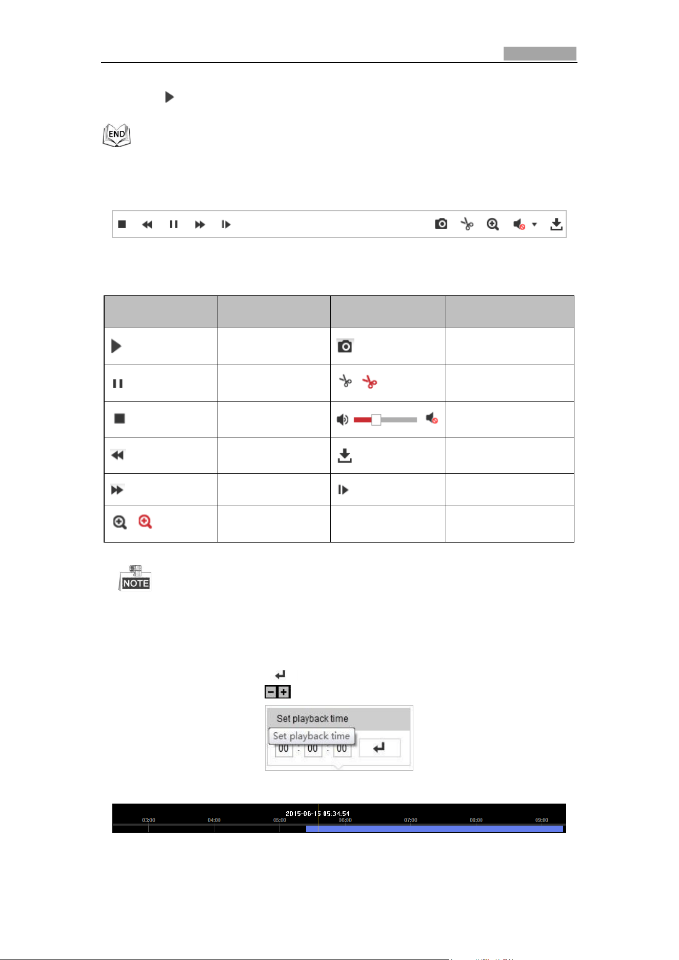
3. Click to play the video files found on this date.
The toolbar on the bottom of Playback interface can be used to control playing
process.
Figure 4-16 Playback Toolbar
Table 4-4 Description of the buttons
Button
Operation
Button
Operation
Play
Capture a picture
Pause
/
Start/Stop clipping
video files
Stop
/
Audio on and adjust
volume/Mute
Speed down
Download
Speed up
Playback by frame
/
Enable/Disable
digital zoom
You can choose the file paths locally for downloaded playback video files and
pictures in Local Configuration interface. Please refer to Section 4.2
Configuring Local Parameters for details.
Drag the progress bar with the mouse to locate the exact playback point. You can
also input the time and click to locate the playback point in the Set playback
time field. You can also click to zoom out/in the progress bar.
Figure 4-17 Set Playback Time
Figure 4-18 Progress Bar
Network Speed Dome User Manual
43
The different colors of the video on the progress bar stand for the different video
types as shown in Figure 4-19.
Figure 4-19 Video Types
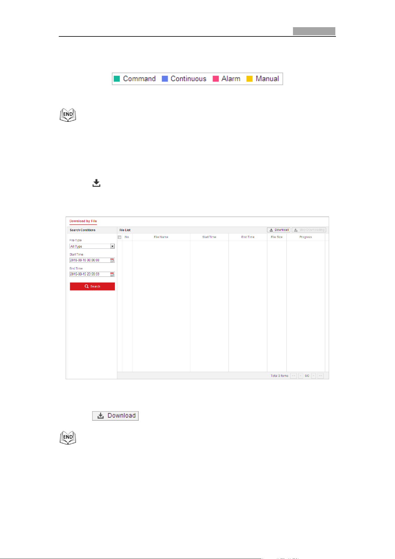
Downloading Video Files
Steps:
1. Click on the playback interface. The pop-up menu is shown in Figure 4-20.
2. Set the start time and end time. Click Search. The corresponding video files will
be listed.
Figure 4-20 Video Downloading interface
3. Check the checkbox in front of the video files that you need to download.
4. Click to download the video files.
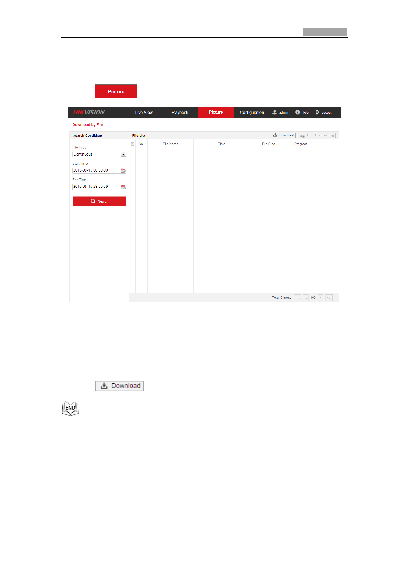
4.7 Picture
Purpose:
Network Speed Dome User Manual
44
This section explains how to view the captured picture files stored in the network
disks and download the captured pictures.
Steps:
1. Click on the menu bar to enter picture interface.
Figure 4-21 Picture Interface
2. Select the file type of capturing the pictures from the list as timing, alarm,
motion, etc..
3. Set the start time and end time. Click Search. The corresponding picture files will
be listed.
4. Check the checkbox in front of the files that you need to download.
5. Click to download the files.
Network Speed Dome User Manual
45
Chapter 5 System Configurations
5.1 Storage Settings
Before you start:
To configure record settings, please make sure that you have the network storage
device within the network or the storage card has been inserted in the corresponding
card slot. Refer to the installation guide for the location of the storage card slot.
5.1.1 Configuring Recording Schedule
Before you start:
Please make sure a local storage card is inserted in the speed dome or the network
storage is added to the speed dome, and the
Purpose:
There are two kinds of recording for the speed domes: manual recording and
scheduled recording. In this section, you can follow the instructions to configure the
scheduled recording. By default, the record files of scheduled recording are stored in
the SD card (if supported) or in the network disk.
Steps:
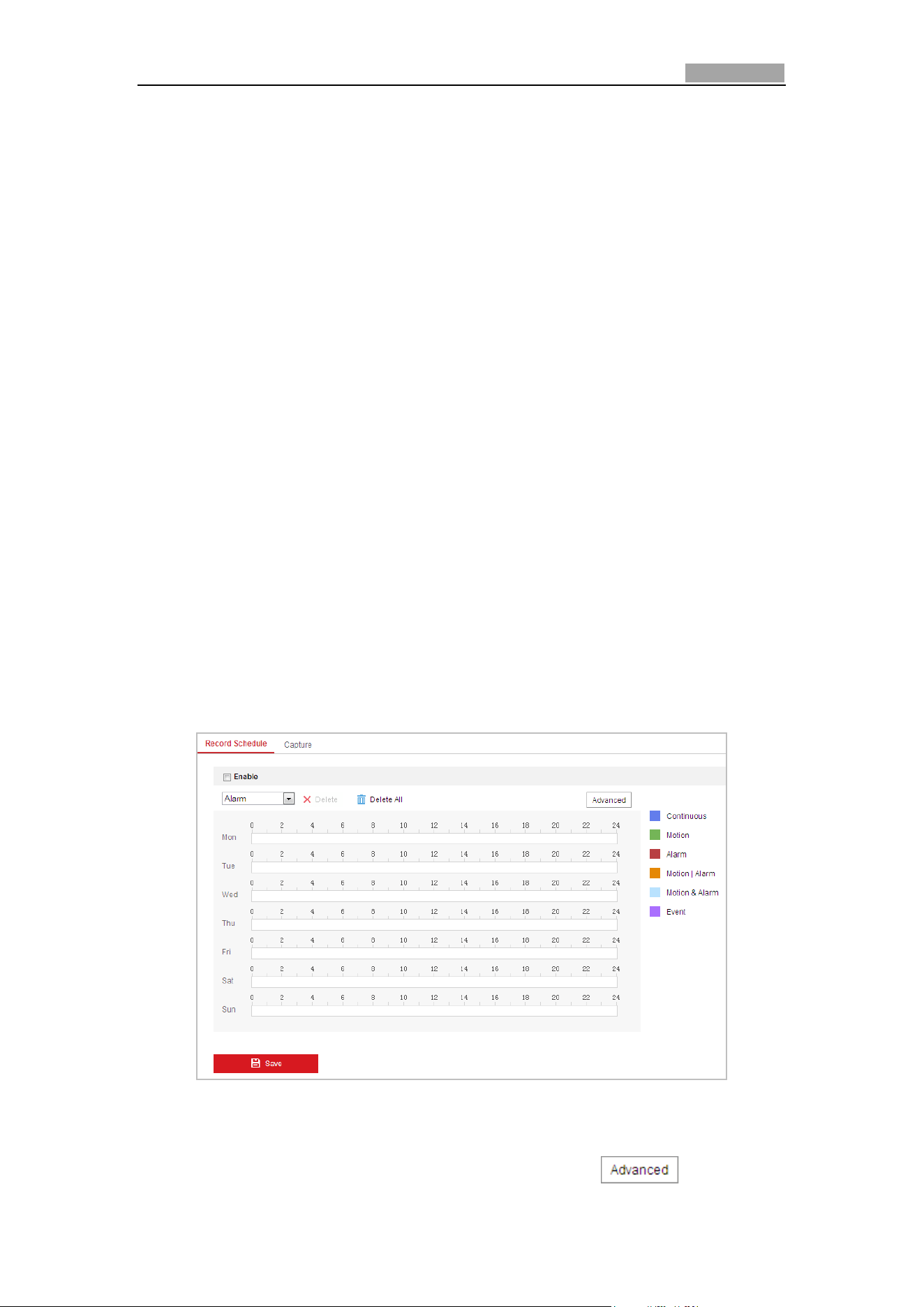
1. Enter the Record Schedule Settings interface:
Configuration > Storage > Schedule Settings > Record Schedule
Figure 5-1 Recording Schedule Interface
2. Check the checkbox of Enable to enable scheduled recording.
3. To set the advanced settings of the speed dome, click to enter the
Network Speed Dome User Manual
46
advanced settings interface.
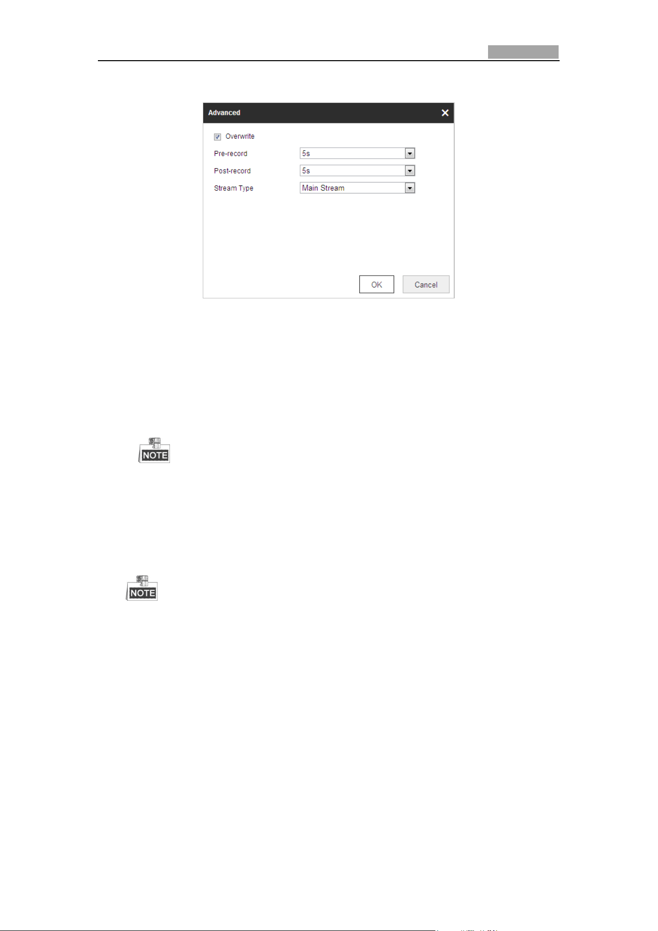
Figure 5-2 Record Parameters
Pre-record: The time you set to start recording before the scheduled time or
the event. For example, if an alarm triggers recording at 10:00, and the
pre-record time is set as 5 seconds, the speed dome starts to record at
9:59:55.
The Pre-record time can be configured as No Pre-record, 5 s, 10 s, 15 s, 20 s,
25 s, 30 s or not limited.
The pre-record time changes according to the video bitrate.
Post-record: The time you set to stop recording after the scheduled time or
the event. For example, if an alarm triggered recording ends at 11:00, and the
post-record time is set as 5 seconds, the speed dome records until 11:00:05.
The Post-record time can be configured as 5 s, 10 s, 30 s, 1 min, 2 min, 5 min
or 10 min.
The Pre-record and Post-record parameters vary depending on the speed
dome model.
Overwrite: If you enable this function and the HDD is full, the new record
files overwrite the oldest record files automatically.
Stream Type: You can select the stream type for recording; Main stream and
Sub Stream are selectable. If you select the sub stream, you can record for a
longer time with the same storage capacity.
4. Click OK to save the advanced setting.
Network Speed Dome User Manual
47
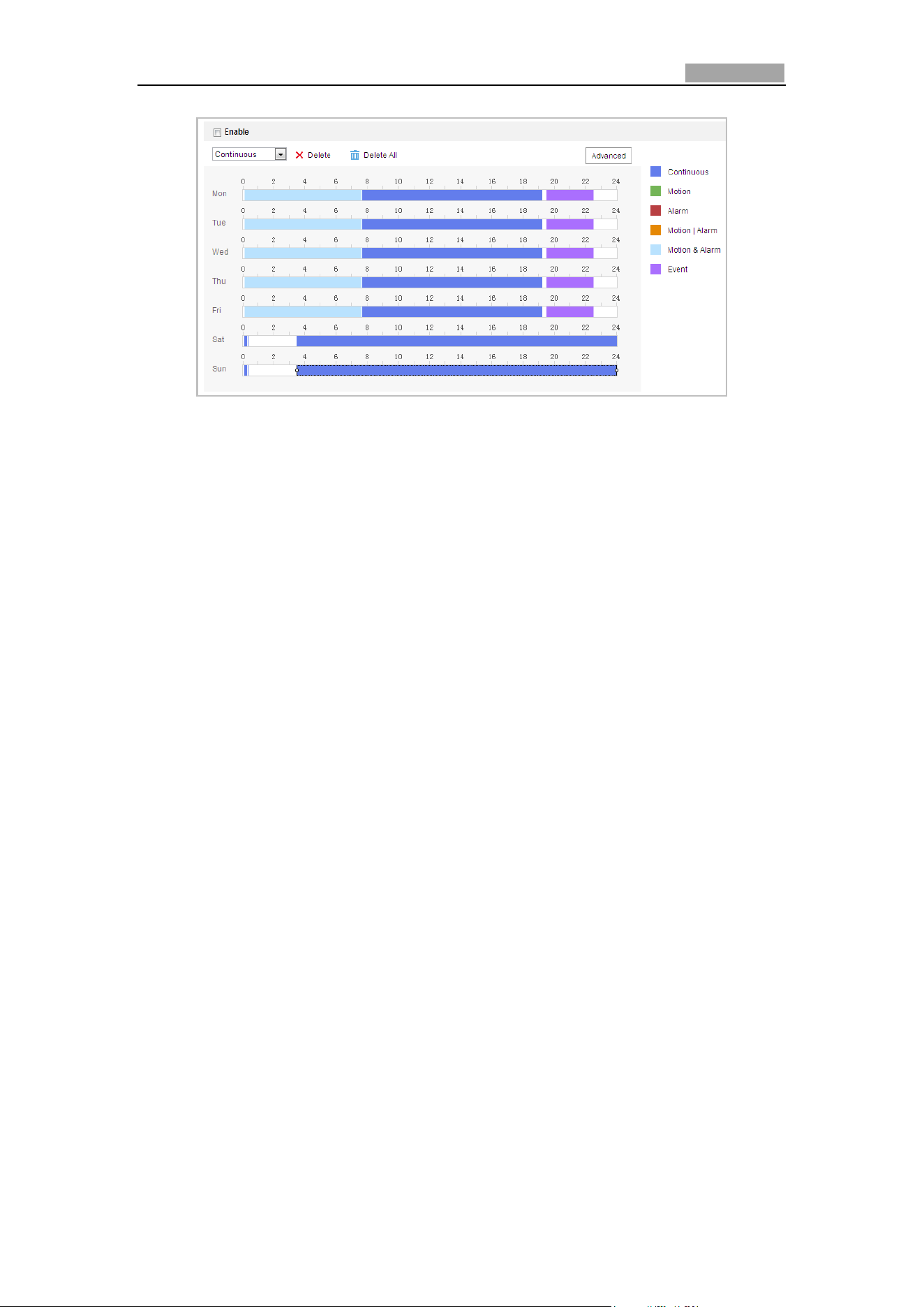
Figure 5-3 Record Schedule
5. Set the record schedule:
(1) Select a Record Type. The record type can be Continuous, Motion Detection,
Alarm, Motion | Alarm, Motion & Alarm, Face Detection, Intrusion Detection,
Line Crossing Detection, Audio Exception Detection and All events.
Continuous
If you select Continuous, the video will be recorded automatically according
to the time of the schedule.
Record Triggered by Motion Detection
If you select Motion Detection, the video will be recorded when the motion
is detected.
Besides configuring the recording schedule, you have to set the motion
detection area and check the checkbox of Trigger Channel in the Linkage
Method of Motion Detection Settings interface. For detailed information,
please refer to the Step 1 in the Section 5.2.1 Configuring Motion Detection.
Record Triggered by Alarm
If you select Alarm, the video will be recorded when the alarm is triggered
via the external alarm input channels.
Besides configuring the recording schedule, you have to set the Alarm Type
and check the checkbox of Trigger Channel in the Linkage Method of Alarm
Input Settings interface. For detailed information, please refer to Section
5.2.4 Configuring Alarm Input.
Record Triggered by Motion & Alarm
If you select Motion & Alarm, the video will be recorded when the motion
and alarm are triggered at the same time.
Besides configuring the recording schedule, you have to configure the
settings on the Motion Detection and Alarm Input Settings interfaces.
Please refer to Section 5.2.1 and Section 5.2.4 for detailed information.
Record Triggered by Motion | Alarm
If you select Motion | Alarm, the video will be recorded when the external
alarm is triggered or the motion is detected.
Besides configuring the recording schedule, you have to configure the
Network Speed Dome User Manual
48
settings on the Motion Detection and Alarm Input Settings interfaces.
Please refer to Section 5.2.1 and Section 5.2.4 for detailed information.
Record Triggered by Audio Exception Detection
If you select Audio Exception Detection, the video will be recorded when
the audio exception is detected.
Besides configuring the recording schedule, you have to configure the
settings on the Audio Exception Detection interface. Please refer to Section
5.3.1 for detailed information.
Record Triggered by Other Smart Events
The smart events include Line Crossing Detection, Intrusion Detection,
Region Entrance Detection and Region Exiting Detection. If you select to
record by one type of the smart events, the video will be recorded when the
selected smart event is triggered. Besides configuring the recording schedule,
you have to configure the settings on the specific event settings interface.
Record Triggered by All Events
If you select All Events, the video will be recorded when any event is
detected.
(2) Select the timeline of a certain day, click and drag the left button of the
mouse to set the recording schedule (the start time and end time of the
recording task).
(3) After you set the scheduled task, you can click and copy the task to
other days (optional).
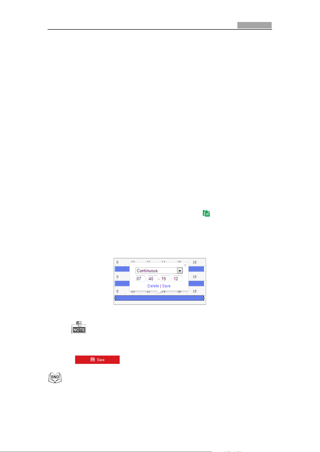
(4) After setting the record schedule, you can click a record segment to display
the segment record settings interface to edit the segment record parameters.
(optional)
Figure 5-4 Segment Record Settings
The time of each segment cannot be overlapped. Up to 8 segments can
be configured for each day.
6. Click to save the settings.
Network Speed Dome User Manual
49
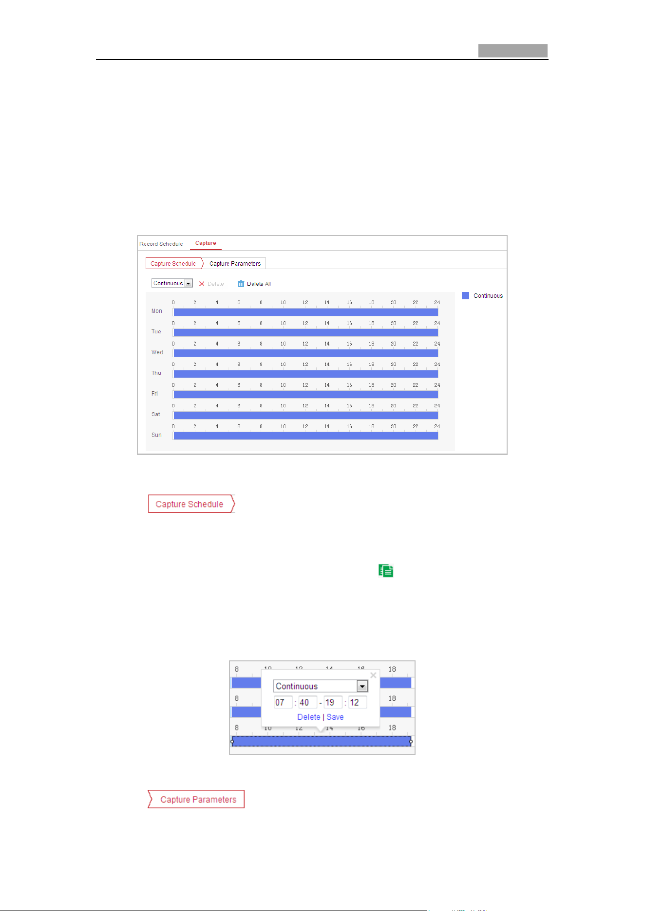
5.1.2 Configuring Capture Schedule
Purpose:
You can configure the scheduled snapshot and event-triggered snapshot. The
captured picture can be stored in the local storage or network storage. Basic Settings
Steps:
1. Enter the Snapshot Settings interface:
Configuration > Storage > Storage Settings > Capture
Figure 5-5 Snapshot Settings
2. Click to enter the Capture Schedule interface.
3. Select the timeline of a certain day, click and drag the left button of the mouse to
set the capture schedule (the start time and end time of the recording task).
4. After you set the scheduled task, you can click and copy the task to other
days (optional).
5. After setting the capture schedule, you can click a capture segment to display the
segment capture settings interface to edit the segment capture parameters.
(optional)
Figure 5-6 Segment Snapshot Settings
6. Click to enter the Capture Parameters Interface.
Network Speed Dome User Manual
50
7. Check the Enable Timing Snapshot checkbox to enable continuous snapshot, and
configure the schedule of timing snapshot. Check the Enable Event-triggered
Snapshot checkbox to enable event-triggered snapshot.
8. Select the format, resolution, quality of the snapshot.
9. Set the time interval between two snapshots.
10. Click to save the settings.
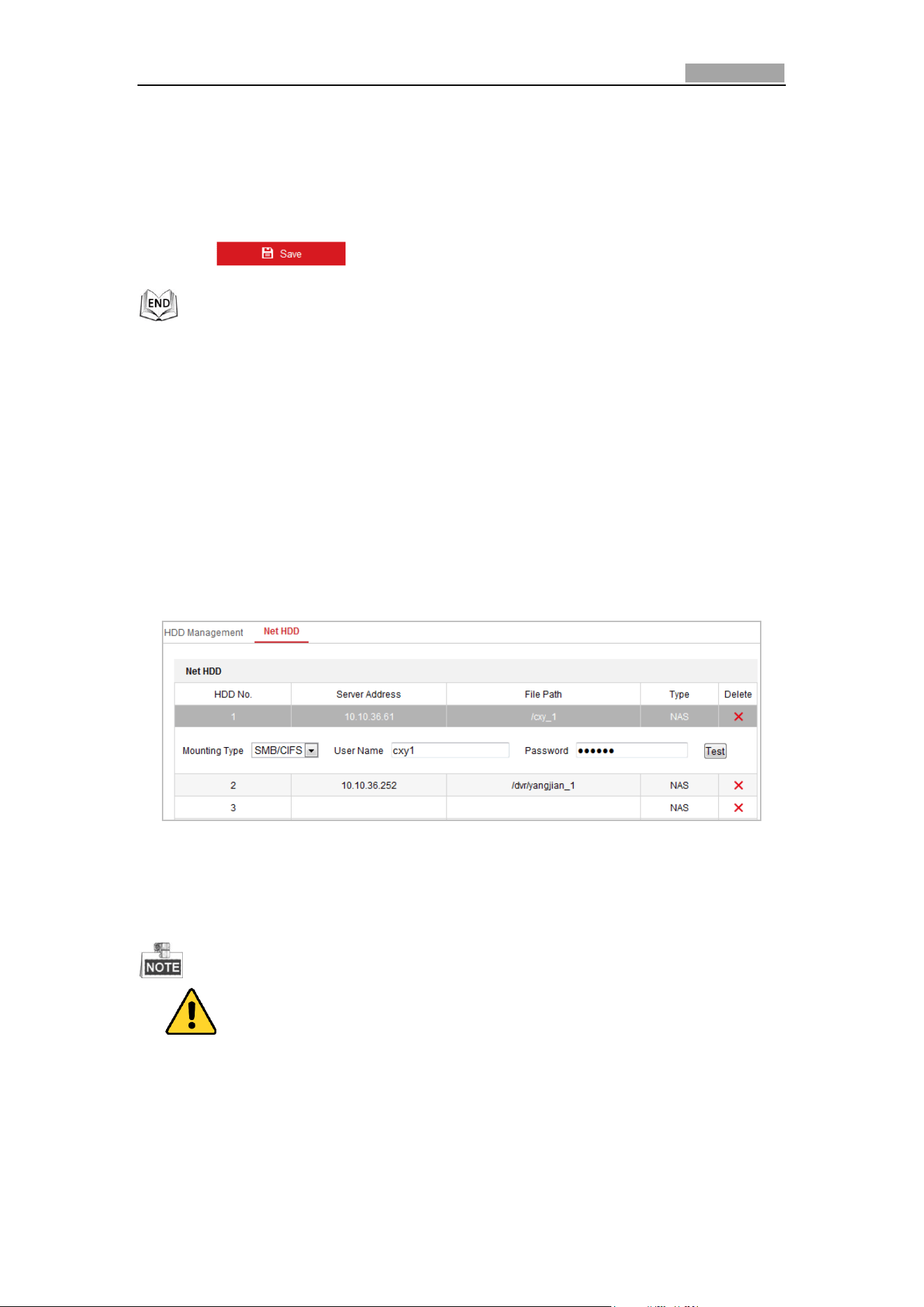
5.1.3 Configuring Net HDD
Before you start:
The network disk should be available within the network and properly configured to
store the recorded files, log files, etc.
Steps:
Add Net HDD
1. Enter the NAS (Network-Attached Storage) Settings interface:
Configuration > Storage > Storage Management > Net HDD
Figure 5-7 Select Net HDD Type
2. Enter the IP address and the file path of the network disk.
3. Select the mounting type. NFS and SMB/CIFS are selectable. You can set the user
name and password to guarantee the security if SMB/CIFS is selected.
Please refer to the NAS User Manual for creating the file path.
For your privacy and to better protect your system against security risks, we
strongly recommend the use of strong passwords for all functions and
network devices. The password should be something of your own choosing
(Using a minimum of 8 characters, including at least three of the following
categories: upper case letters, lower case letters, numbers, and special
characters.) in order to increase the security of your product.
Network Speed Dome User Manual
51
Proper configuration of all passwords and other security settings is the
responsibility of the installer and/or end-user.
4. Click to save the settings.
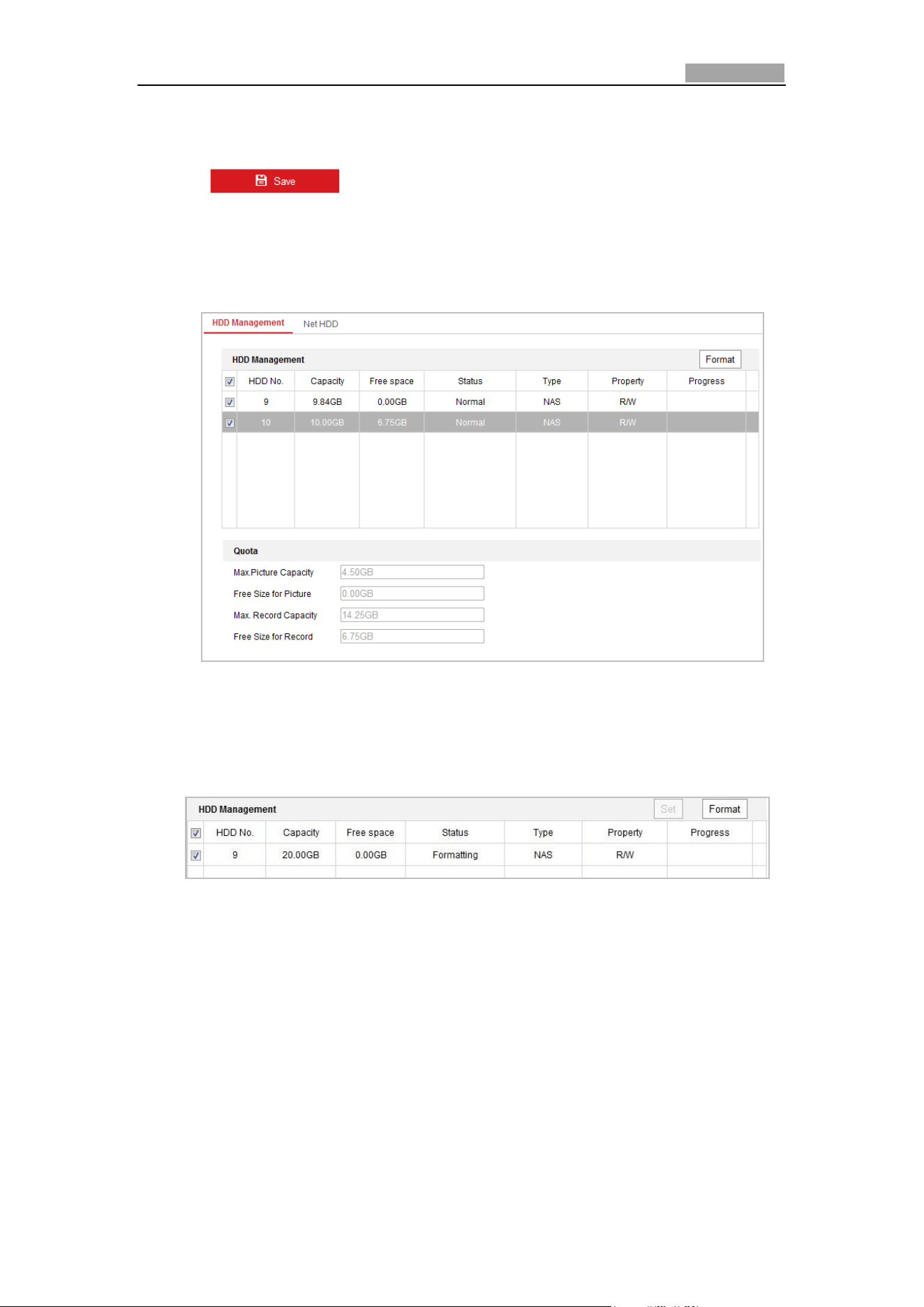
Initialize Added Network Disk
1. Enter the HDD Settings interface, Configuration > Storage > Storage
Management > HDD Management, in which you can view the capacity, free space,
status, type and property of the disk.
Figure 5-8 Storage Management Interface
2. If the status of the disk is Uninitialized, check the corresponding checkbox to
select the disk and click Format to start initializing the disk.
When the initialization completed, the status of disk will become Normal.
Figure 5-9 View Disk Status
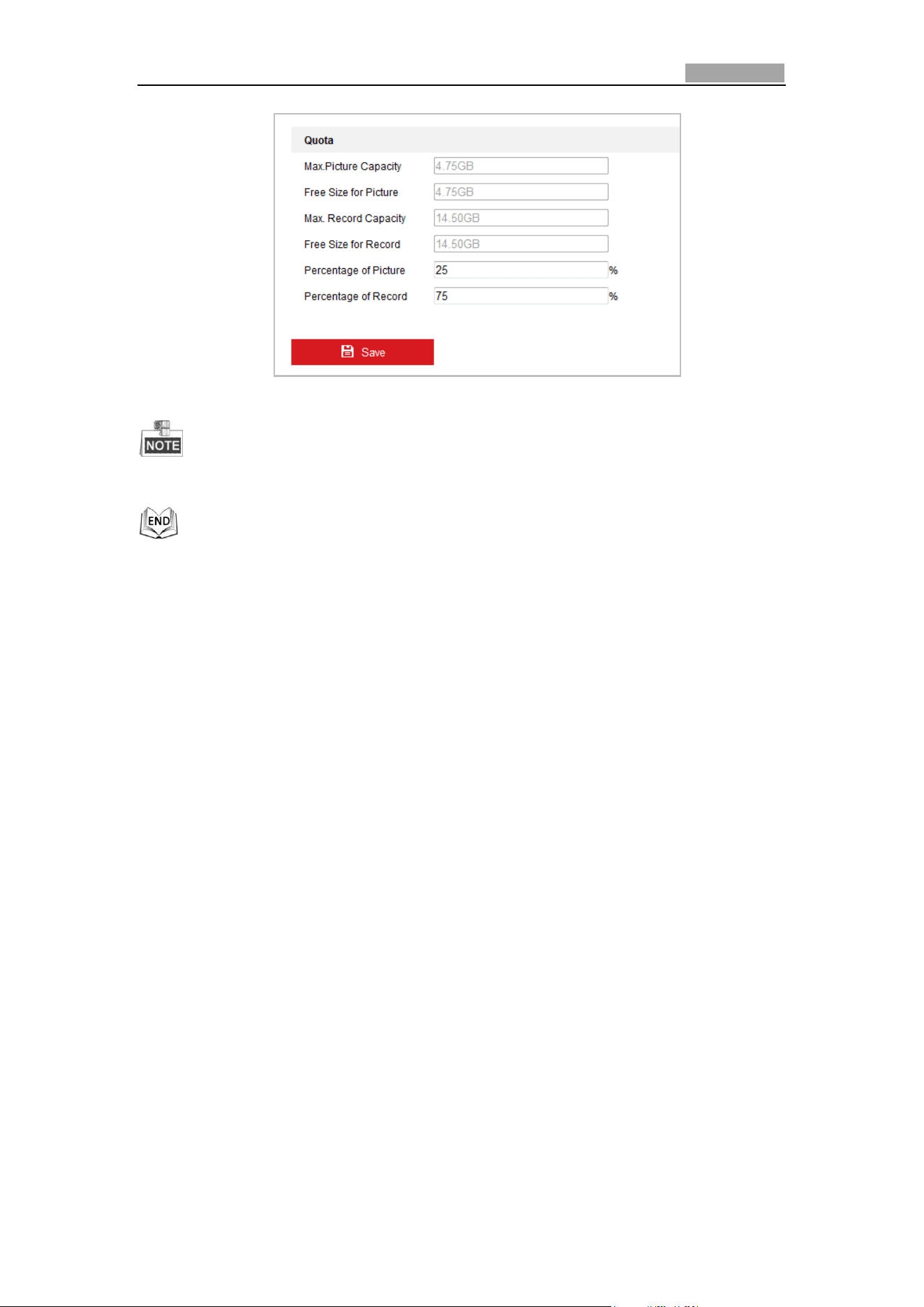
Define the Quota for Record and Pictures
1. Input the quota percentage for picture and for record.
2. Click Save and refresh the browser page to activate the settings.
Network Speed Dome User Manual
52
Figure 5-10 Quota Settings
Up to 8 NAS disks can be connected to the camera.
5.2 Basic Event Configuration
Purpose:
This section explains how to configure the network speed dome to respond to alarm
events, including motion detection, external alarm input, video loss, tamper-proof
and exception. These events can trigger the alarm actions, such as Notify Surveillance
Center, Send Email, Trigger Alarm Output, etc.
For example, when an external alarm is triggered, the network speed dome sends a
notification to an e-mail address.
5.2.1 Configuring Motion Detection
Purpose:
Motion detection is a feature which can trigger alarm actions and actions of
recording videos when the motion occurred in the surveillance scene.
Steps:
1. Enter the motion detection setting interface:
Configuration > Event > Basic Event > Motion Detection
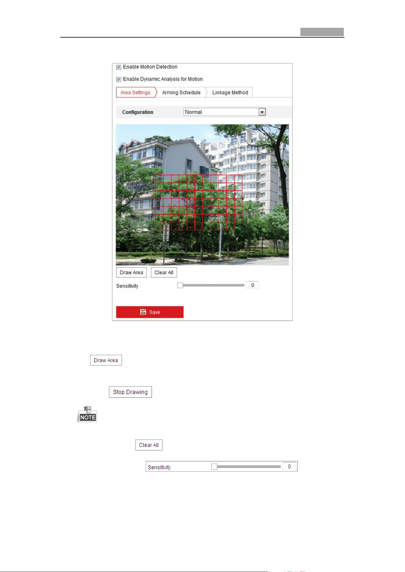
2. Check the checkbox of the Enable Motion Detection to enable this function.
You can check the Enable Dynamic Analysis for Motion checkbox if you want the
detected object get marked with rectangle in the live view.
3. Select the configuration mode as Normal or Expert and set the corresponding
motion detection parameters.
Network Speed Dome User Manual
53
Normal
Figure 5-11 Motion Detection Settings-Normal
Steps:
(1) . Click and drag the mouse on the live video image to draw a
motion detection area.
(2) Click to finish drawing.
• You can draw up to 8 motion detection areas on the same image.
• You can click to clear all of the areas.
(3) Move the slider to set the
sensitivity of the detection.
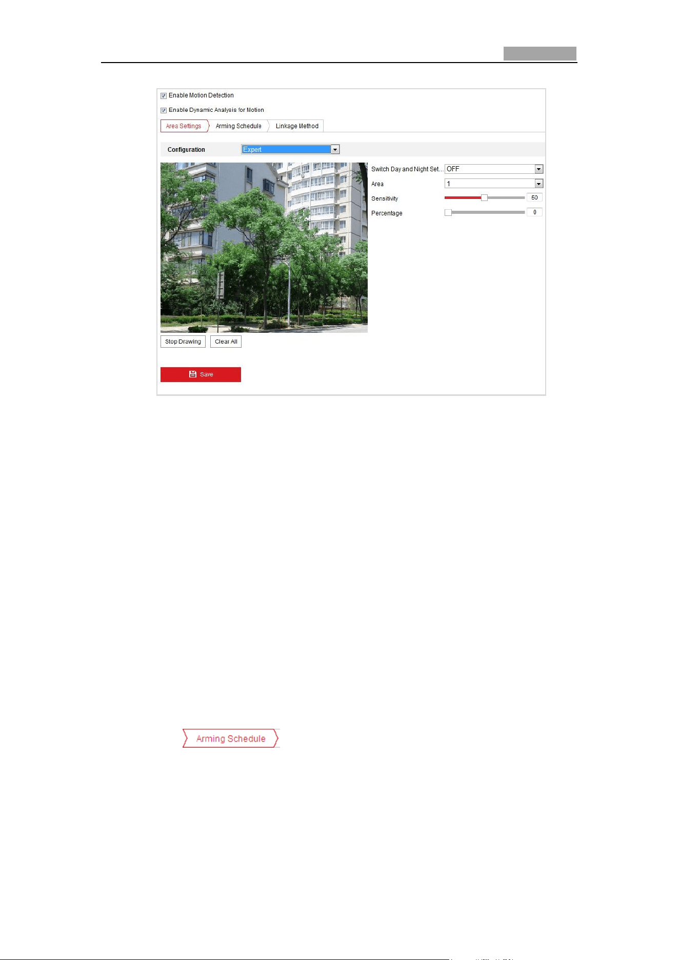
Expert
Network Speed Dome User Manual
54
Figure 5-12 Motion Detection Settings-Expert
Steps:
(1) Set the Day&Night switch mode, there are OFF, Auto-Switch and
Scheduled-Switch selectable. If the Day&Night switch mode is enabled, you
can configure the detection rule for the day and night separately.
OFF: Disable the day and night switch.
Auto-Switch: Switch the day and night mode according to the illumination
automatically.
Scheduled-Switch: Switch to the day mode at 6:00 a.m., and switch to the
night mode at 18:00 p.m..
(2) Select Area No. to configure in the dropdown list.
(3) Set the values of sensitivity and proportion of object on area.
Sensitivity: The greater the value is, the easier the alarm will be triggered.
Proportion of Object on Area: When the size proportion of the moving
object exceeds the predefined value, the alarm will be triggered. The less
the value is, the easier the alarm will be triggered.
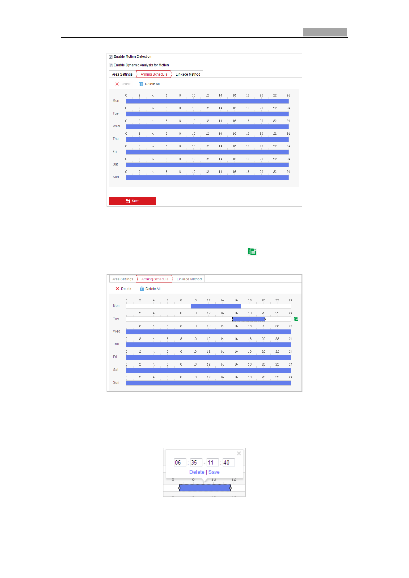
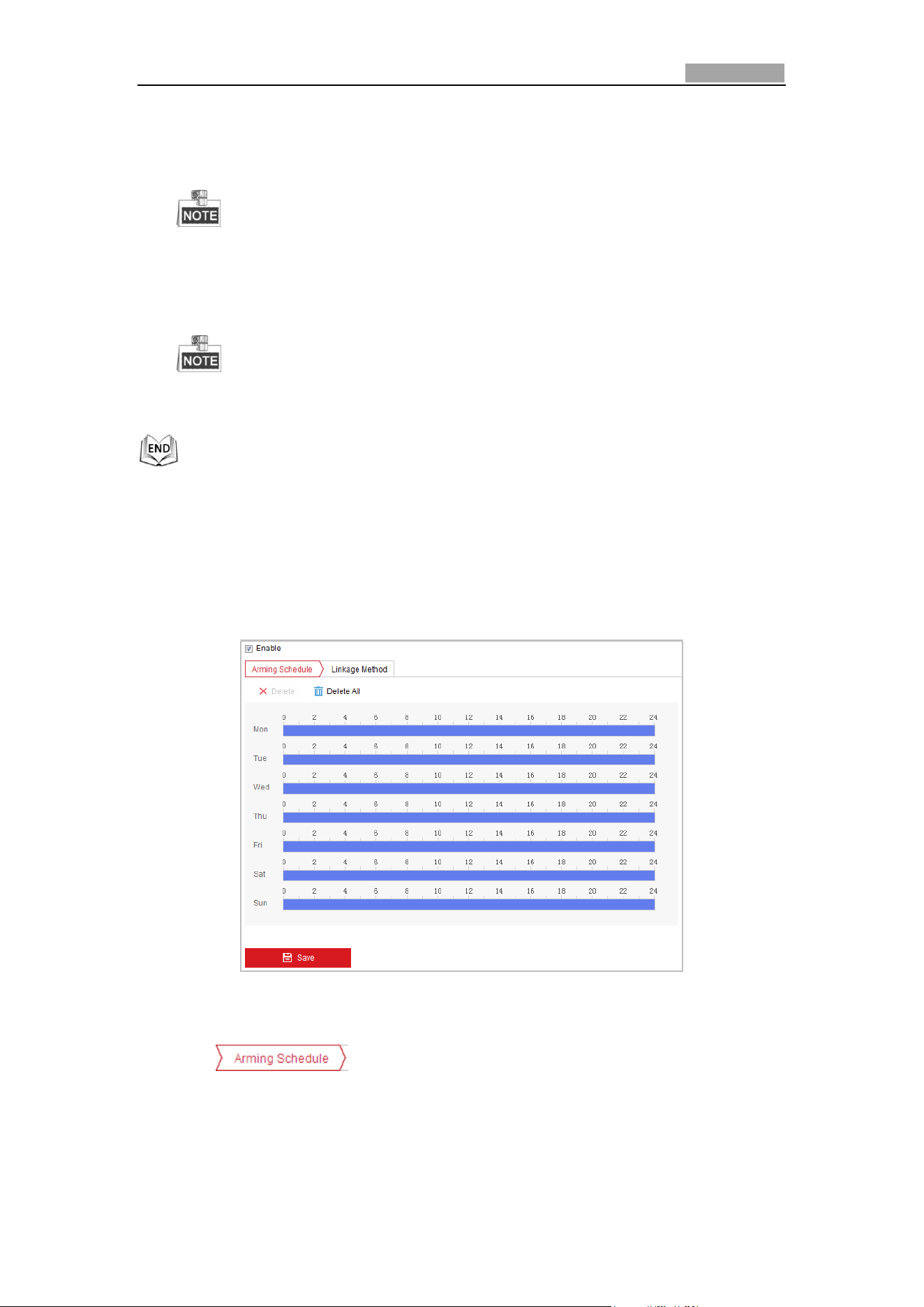
4. Set the Arming Schedule for Motion Detection.
(1) Click tab to enter the arming schedule setting interface.
Network Speed Dome User Manual
55
Figure 5-13 Arming Schedule
(2) Select the timeline of a certain day, click and drag the mouse to set the
arming schedule (the start time and end time of the arming task).
(3) After you set the scheduled task, you can click and copy the task to
other days (optional).
Figure 5-14 Arming Time Schedule
(4) After setting the arming schedule, you can click a segment to display the
segment arming settings interface to edit the segment record parameters
(optional).
Figure 5-15 Segment Arming Settings
Network Speed Dome User Manual
56
(5) Click to save the settings.
The time of each period cannot be overlapped. Up to 8 periods can be
configured for each day.
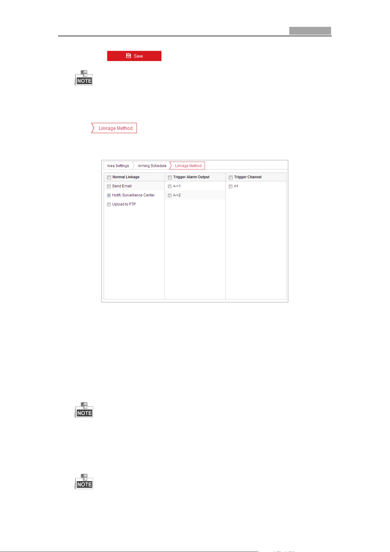
5. Set the Alarm Actions for Motion Detection.
Click tab to enter the Linkage Method interface.
You can specify the linkage method when an event occurs. The following
contents are about how to configure the different types of linkage method.
Figure 5-16 Linkage Method
Check the checkbox to select the linkage method. Notify surveillance center,
send email, upload to FTP, trigger channel and trigger alarm output are
selectable.
Notify Surveillance Center
Send an exception or alarm signal to remote management software when an
event occurs.
Send Email
Send an email with alarm information to a user or users when an event occurs.
To send the Email when an event occurs, you need to refer to Section 0
Configuring Email Settings to set the Email parameters.
Upload to FTP
Capture the image when an alarm is triggered and upload the picture to a FTP
server.
You need a FTP server and set FTP parameters first. Refer to Section 0
Network Speed Dome User Manual
57
Configuring FTP Settings for setting FTP parameters.
Trigger Channel
Record a video when an event occurs.
You have to set the recording schedule to realize this function. Please refer
to Section 5.1 Storage Settings for settings the recording schedule.
Trigger Alarm Output
Trigger one or more external alarm outputs when an event occurs.
To trigger an alarm output when an event occurs, please refer to Section
5.2.5 Configuring Alarm Output to set the alarm output parameters.
5.2.2 Configuring Video Loss Alarm
Steps:
1. Enter the Video Loss Setting interface:
Configuration > Event > Basic Event > Video Loss
Figure 5-17 Video Loss
2. Check the Enable checkbox to enable the video loss detection.
3. Click tab to enter the arming schedule setting interface. The
arming schedule configuration is the same as the setting of the arming schedule
for motion detection. Refer to Step 2 in Section 5.2.1 Configuring Motion
Detection.
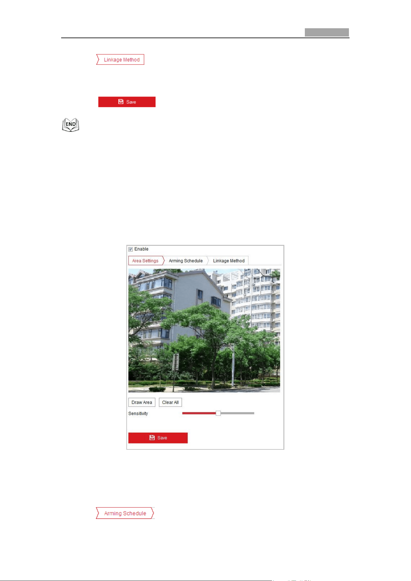
Network Speed Dome User Manual
58
4. Click tab to select the linkage method taken for the video loss
alarm, notify surveillance center, send email and trigger alarm output are
selectable. Please Step 3 in Section 5.2.1 Configuring Motion Detection.
5. Click to save the settings.
5.2.3 Configuring Video Tampering Alarm
Purpose:
You can configure the speed dome to trigger the alarm actions when the lens is
covered.
Steps:
1. Enter the video tampering Settings interface:
Configuration > Event > Basic Event > Video Tampering
Figure 5-18 Tampering Alarm
2. Check Enable checkbox to enable the tampering detection.
3. Set the tampering area. Refer to Step 1 in Section 5.2.1 Configuring Motion
Detection.
4. Click tab to enter the arming schedule setting interface. The
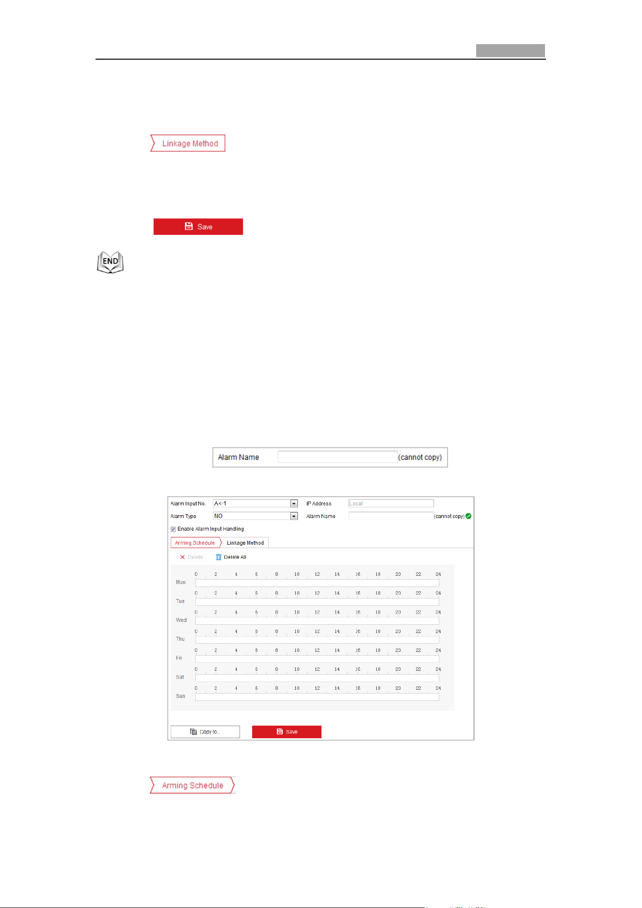
Network Speed Dome User Manual
59
arming schedule configuration is the same as the setting of the arming schedule
for motion detection. Refer to Step 2 in Section 5.2.1 Configuring Motion
Detection.
5. Click tab to select the linkage method taken for the video loss
alarm, including Notify surveillance center, send email, trigger channel, smart
tracking and trigger alarm output are selectable. Please refer to Step 3 in Section
5.2.1 Configuring Motion Detection.
6. Click to save the settings.
5.2.4 Configuring Alarm Input
Steps:
1. Enter the Alarm Input Settings interface:
Configuration > Event > Basic Event > Alarm Input
2. Choose the alarm input No. and the Alarm Type. The alarm type can be NO
(Normally Open) and NC (Normally Closed).
3. Edit the name in to set a name for
the alarm input (optional).
Figure 5-19 Alarm Input Settings
4. Click tab to enter the arming schedule setting interface. The
arming schedule configuration is the same as the setting of the arming schedule
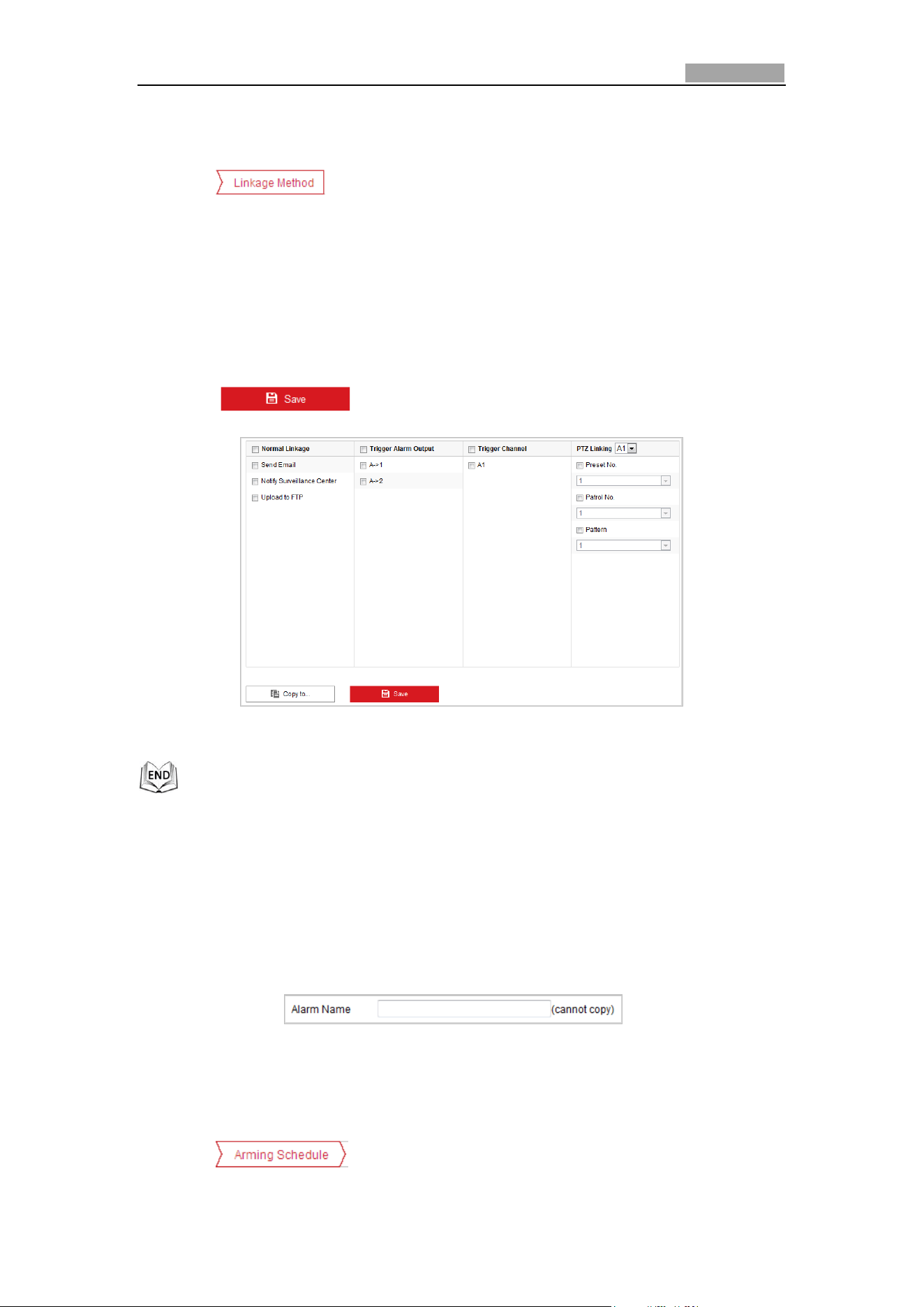
Network Speed Dome User Manual
60
for motion detection. Refer to Step 2 in Section 5.2.1 Configuring Motion
Detection.
5. Click tab to select the linkage method taken for the video loss
alarm, including Notify surveillance center, send email, trigger channel, smart
tracking and trigger alarm output are selectable. Please Step 3 in Section 5.2.1
Configuring Motion Detection.
6. You can also choose the PTZ linking for the alarm input. Check the relative
checkbox and select the No. to enable Preset Calling, Patrol Calling or Pattern
Calling.
7. You can copy your settings to other alarm inputs.
8. Click to save the settings.
Figure 5-20 Linkage Method
5.2.5 Configuring Alarm Output
Steps:
1. Enter the Alarm Output Settings interface:
Configuration> Event > Basic Event > Alarm Output
2. Select one alarm output channel in the Alarm Output drop-down list.
3. Set a name in for the alarm
output (optional).
4. The Delay time can be set to 5sec, 10sec, 30sec, 1min, 2min, 5min, 10min or
Manual. The delay time refers to the time duration that the alarm output
remains in effect after alarm occurs.
5. Click tab to enter the arming schedule setting interface. The
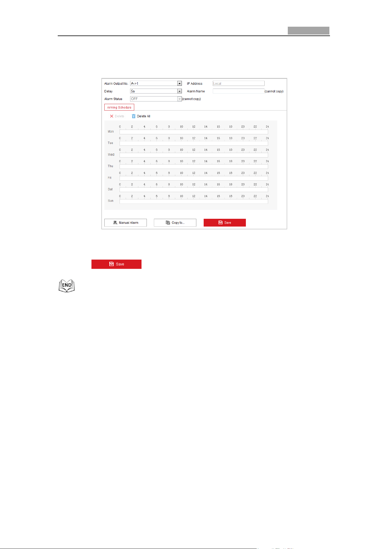
Network Speed Dome User Manual
61
time schedule configuration is the same as the settings of the arming schedule
for motion detection. Refer to Step 2 in Section 5.2.1 Configuring Motion
Detection.
Figure 5-21 Alarm Output Settings
6. You can copy the settings to other alarm outputs.
7. Click to save the settings.
5.2.6 Handling Exception
The exception type can be HDD full, HDD error, network disconnected, IP address
conflicted and illegal login to the speed domes.
Steps:
1. Enter the Exception Settings interface:
Configuration > Event > Basic Event > Exception
2. Check the checkbox to set the actions taken for the Exception alarm. Refer to
Step 3 in Section 5.2.1 Configuring Motion Detection.
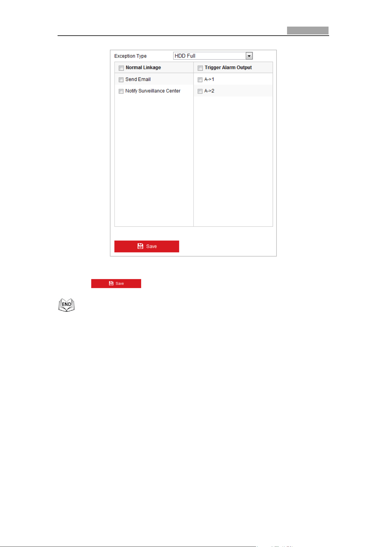
Network Speed Dome User Manual
62
Figure 5-22 Exception Settings
3. Click to save the settings.
5.3 Smart Event Configuration
5.3.1 Detecting Audio Exception
Purpose:
When you enable this function and audio exception occurs, the alarm actions will be
triggered.
Steps:
1. Enter the video audio exception detection interface:
Configuration > Event > Smart Event > Audio Exception Detection
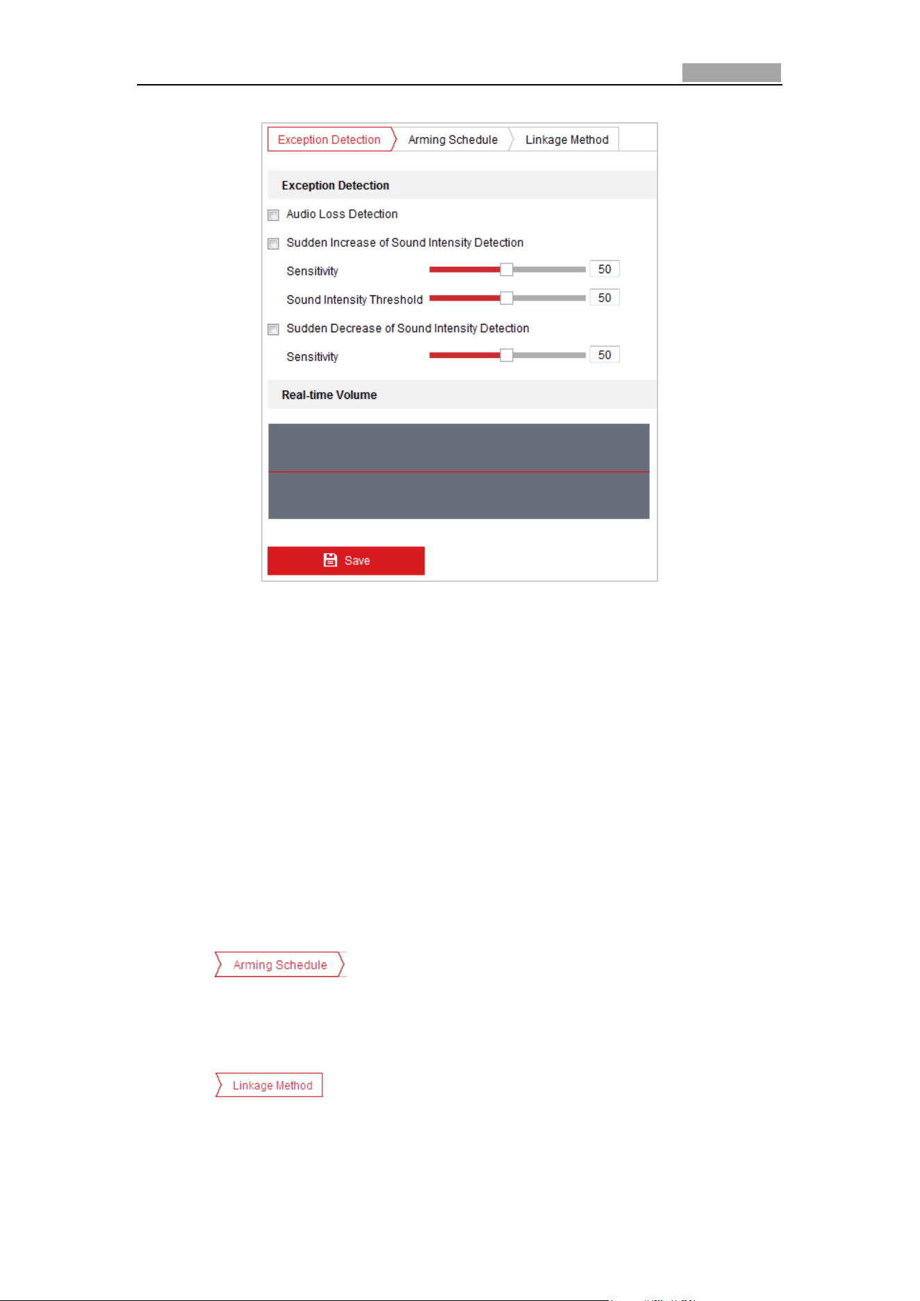
Network Speed Dome User Manual
63
Figure 5-23 Audio Exception Detection
2. Check the checkbox of Audio Loss Detection to enable the audio input exception
detection.
3. Check the checkbox of Sudden Increase of Sound Intensity Detection checkbox
to enable the sudden rise detection.
Sensitivity: Range [1-100], the smaller the value the more severe the sound
change will trigger the detection.
Sound Intensity Threshold: Range [1-100], it can filter the sound in the
environment, the louder the environment sound, the higher the value should
be. You can adjust it according to the actual environment.
4. Check the checkbox of Sudden Decrease of Sound Intensity Detection checkbox
to enable the sudden drop detection.
Sensitivity: Range [1-100], the smaller the value the more severe the sound
change will trigger the detection.
5. Click tab to enter the arming schedule setting interface. The
time schedule configuration is the same as the settings of the arming schedule
for motion detection. Refer to Step 2 in Section 5.2.1 Configuring Motion
Detection.
6. Click tab to select the linkage method taken for the video loss
alarm, Notify surveillance center, send email, trigger channel, smart tracking and
trigger alarm output are selectable. Please refer to Step 3 in Section 5.2.1
Configuring Motion Detection.
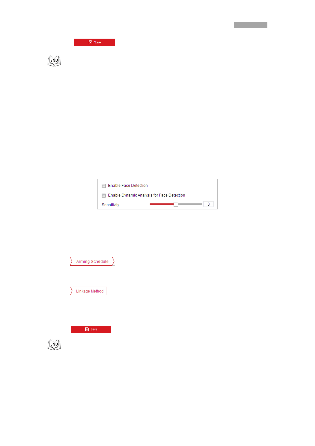
Network Speed Dome User Manual
64
7. Click to save the settings.
5.3.2 Configuring Face Detection
Purpose:
After the face detection is enabled, a face appears in the surveillance area, it will be
detected and certain actions may be triggered by the detection.
Steps:
1. Check the Enable Face Detection checkbox.
2. (Optional) You can check the Enable Dynamic Analysis for Face Detection
checkbox if you want the detected face get marked with rectangle in the live view.
Figure 5-24 Configuring Face Detection
3. Configure the sensitivity for face detection.
Sensitivity: Range [1-5]. The value of the sensitivity defines the size of the object
which can trigger the alarm, when the sensitivity is high, a very small object can
trigger the alarm.
4. Click tab to enter the arming schedule setting interface. The
time schedule configuration is the same as the settings of the arming schedule for
motion detection. Refer to Step 2 in Section 5.2.1 Configuring Motion Detection.
5. Click tab to select the linkage method taken for the video loss
alarm, Notify surveillance center, send email, upload to FTP, trigger channel, smart
tracking and trigger alarm output are selectable. Please Step 3 in Section 5.2.1
Configuring Motion Detection.
6. Click to save the settings.
5.3.3 Configuring Intrusion Detection
Intrusion detection can set an area in the surveillance scene and once the area is
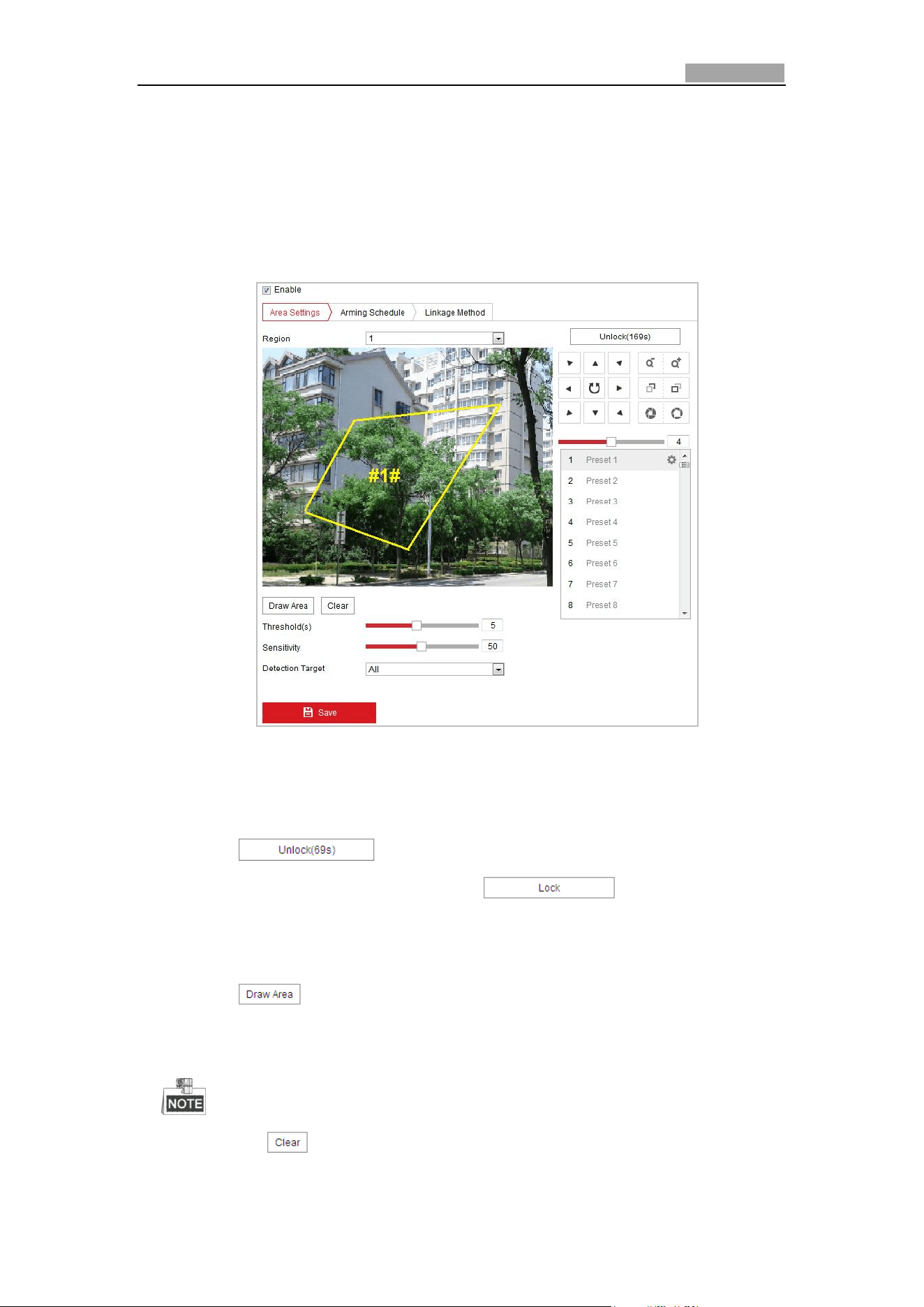
Network Speed Dome User Manual
65
entered, a set of alarm action is triggered.
Steps:
1. Enter the intrusion detection interface:
Configuration > Events > Smart Event >Intrusion Detection
2. Check the Enable checkbox to enable the intrusion detection function.
Figure 5-25 Configuring Intrusion Area
3. The event triggered and park action related PTZ movement will be locked for 180
seconds after you enter the intrusion detection interface. Optionally, you can
click the button to manually activate the movement, or lock
the movement when the button turns to by clicking it.
4. Draw area.
(1) Select the Region No.in dropdown list.
(2) Click to draw a rectangle on the image as a defense region.
(3) Click on the image to specify a corner of the rectangle, and right-click the
mouse after four corners are configured.
Up to four areas are supported.
You can click to clear the areas you drawn.
5. Configure the parameters for each defense region separately.
Network Speed Dome User Manual
66
Threshold: Range [0-10s], the threshold for the time of the object staying in
the region. If you set the value as 0, alarm is triggered immediately after the
object entering the region.
Sensitivity: Range [1-100]. The value of the sensitivity defines the size of the
object which can trigger the alarm, when the sensitivity is high, a very small
object can trigger the alarm.
Detection Target: You can select human, vehicle, or all (human &vehicle) as
the detection target from the dropdown list. If Human is selected, only
human beings will be identified as detection objects and as well as Vehicle.
6. Click tab to enter the arming schedule setting interface. The
time schedule configuration is the same as the settings of the arming schedule
for motion detection. Refer to Step 2 in Section 5.2.1 Configuring Motion
Detection.
7. Click tab to select the linkage method taken for the video loss
alarm, Notify surveillance center, send email, trigger channel, smart tracking and
trigger alarm output are selectable. Please refer to Step 3 in Section 5.2.1
Configuring Motion Detection.
8. Click to save the settings.
5.3.4 Configuring Line Crossing Detection
The virtual plane detection can be adopted for the intrusion detection. Once the
virtual plane is detected being traversed according to the configured direction, a set
of alarm action is triggered.
Steps:
1. Enter the Line Crossing Detection interface:
Configuration >Event > Smart Event > Line Crossing Detection
2. Check the Enable checkbox to enable the line crossing detection function.
3. Select the Line in dropdown list to configure.
4. The event triggered and park action related PTZ movement will be locked for 180
seconds after you enter the line crossing detection interface. Optionally, you can
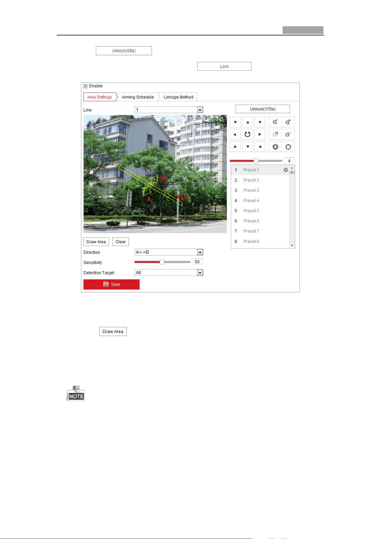
Network Speed Dome User Manual
67
click the button to manually activate the movement, or lock
the movement when the button turns to by clicking it.
Figure 5-26 Configuring Line
5. Draw area.
(1) Click to draw a line on the image.
(2) Click the line to switch to the editing mode.
Click and drag an end to the desired place to adjust the length and angle of
the line. And click and drag the line to adjust the location.
Up to four lines are supported.
6. Configure the parameters for each defense region separately.
Direction: Select the detection direction in the dropdown list, there are A<->B,
A->B and B->A selectable.
Sensitivity: Range [1-100]. The value of the sensitivity defines the size of the
object which can trigger the alarm, when the sensitivity is high, a very small
object can trigger the alarm.
Detection Target: You can select human, vehicle, or all (human &vehicle) as
Network Speed Dome User Manual
68
the detection target from the dropdown list. If Human is selected, only
human beings will be identified as detection objects and as well as Vehicle.
7. Click tab to enter the arming schedule setting interface. The
time schedule configuration is the same as the settings of the arming schedule for
motion detection. Refer to Step 2 in Section 5.2.1 Configuring Motion Detection.
8. Click tab to select the linkage method taken for the video loss
alarm, including Notify surveillance center, send email, upload to FTP, trigger
channel, smart tracking and trigger alarm output are selectable. Please Step 3 in
Section 5.2.1 Configuring Motion Detection.
9. Click to save the settings.
5.3.5 Region Entrance Detection
Purpose:
Region entrance detection function detects people, vehicle or other objects which
enter a pre-defined virtual region from the outside place, and some certain actions
can be taken when the alarm is triggered.
Steps:
1. Enter the Region Entrance Detection settings interface:
Configuration> Event > Smart Event> Region Entrance Detection
2. Check the checkbox of Enable to enable the Region Entrance Detection function.
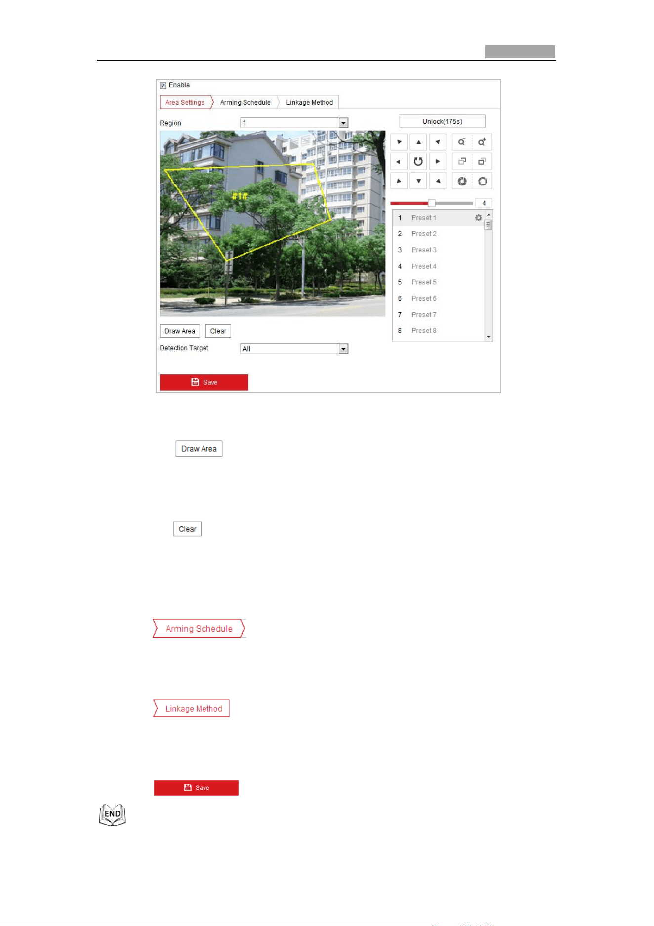
Network Speed Dome User Manual
69
Figure 5-27 Configuring Region Entrance Detection
3. Select the region from the dropdown list for detection settings.
4. Click the button to start the region drawing.
5. Click on the live video to specify the four vertexes of the detection region, and
right click to complete drawing.
Repeat the step to configure other regions. Up to 4 regions can be set. You can
click the button to clear all pre-defined regions.
6. Set the detection target for the region entrance detection. You can select human,
vehicle, or all (human &vehicle) as the detection target from the dropdown list.
If Human is selected, only human beings will be identified as detection objects
and as well as Vehicle.
7. Click tab to enter the arming schedule setting interface. The
time schedule configuration is the same as the settings of the arming schedule
for motion detection. Refer to Step 2 in Section 5.2.1 Configuring Motion
Detection.
8. Click tab to select the linkage method taken for the video loss
alarm, Notify surveillance center, send email, upload to FTP, trigger channel,
smart tracking and trigger alarm output are selectable. Please Step 3 in Section
5.2.1 Configuring Motion Detection.
9. Click to save the settings.
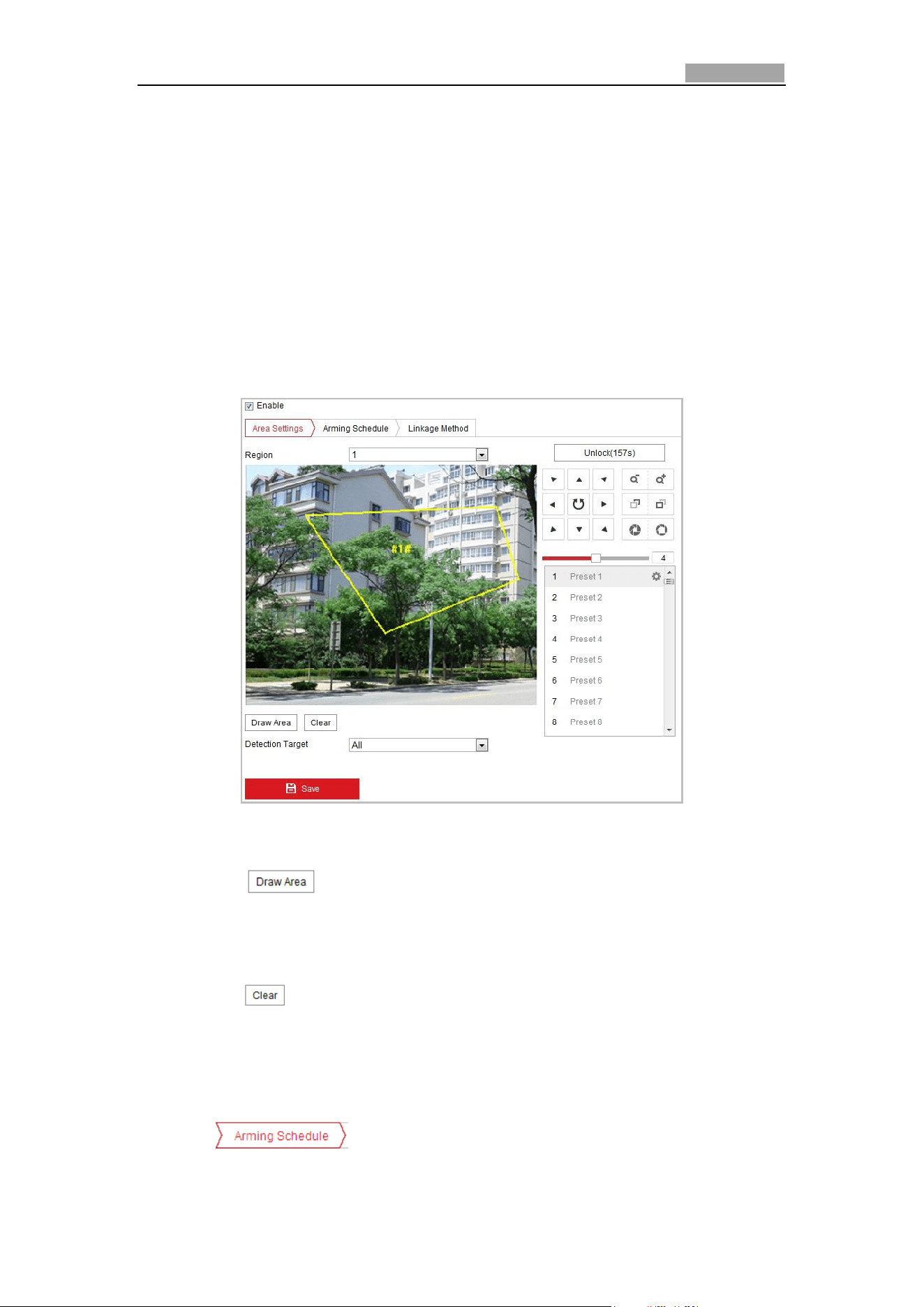
Network Speed Dome User Manual
70
5.3.6 Region Exiting Detection
Purpose:
Region exiting detection function detects people, vehicle or other objects which exit
from a pre-defined virtual region, and some certain actions can be taken when the
alarm is triggered.
Steps:
1. Enter the Region Exiting Detection settings interface:
Configuration> Event > Smart Event> Region Exiting Detection
2. Check the checkbox of Enable to enable the Region Exiting Detection function.
Figure 5-28 Configuring Region Exiting Detection
3. Select the region from the dropdown list for detection settings.
4. Click the button to start the region drawing.
5. Click on the live video to specify the four vertexes of the detection region, and
right click to complete drawing.
Repeat the step to configure other regions. Up to 4 regions can be set. You can
click the button to clear all pre-defined regions.
6. Set the detection target for the region entrance detection. You can select human,
vehicle, or all (human &vehicle) as the detection target from the dropdown list.
If Human is selected, only human beings will be identified as detection objects
and as well as Vehicle.
7. Click tab to enter the arming schedule setting interface. The
time schedule configuration is the same as the settings of the arming schedule
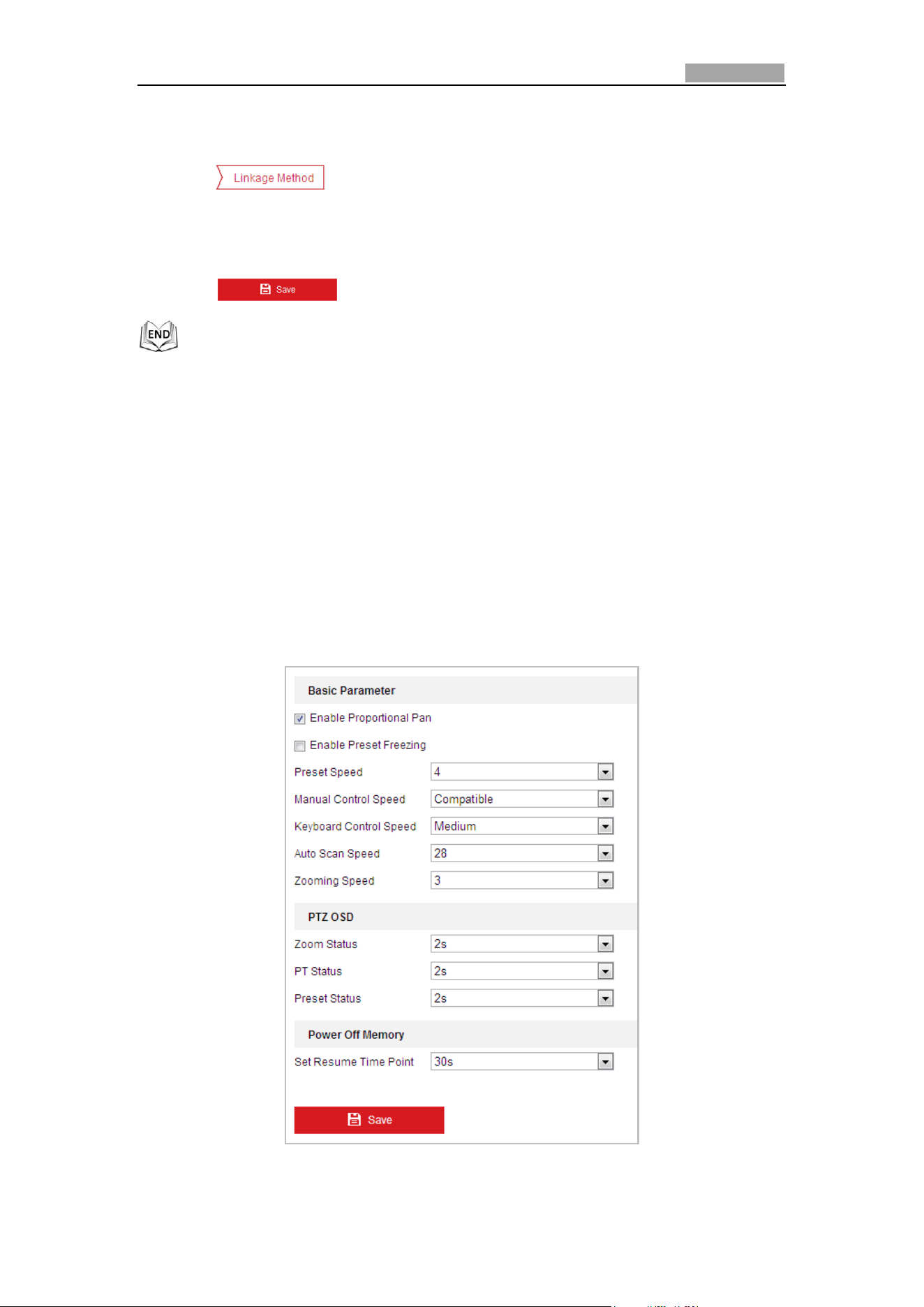
Network Speed Dome User Manual
71
for motion detection. Refer to Step 2 in Section 5.2.1 Configuring Motion
Detection.
8. Click tab to select the linkage method taken for the video loss
alarm, Notify surveillance center, send email, upload to FTP, trigger channel,
smart tracking and trigger alarm output are selectable. Please Step 3 in Section
5.2.1 Configuring Motion Detection.
9. Click button to save the settings.
5.4 PTZ Configuration
5.4.1 Configuring Basic PTZ Parameters
Purpose:
You can configure the basic PTZ parameters, including proportional pan, preset
freezing, preset speed, etc.
1. Enter the Basic PTZ Parameter Configuration interface:
Configuration > PTZ > Basic Settings
Figure 5-29 Basic PTZ Configuration Interface
Network Speed Dome User Manual
72
2. Configure the following settings:
Basic Parameters: Enable/disable proportional pan and preset freezing, set the
preset speed, keyboard control speed, and auto scan speed.
Proportional Pan: If you enable this function, the pan/tilt speeds change
according to the amount of zoom. When there is a large amount of zoom, the
pan/tilt speed will be slower for keeping the image from moving too fast on
the live view image.
Preset Freezing: This function enables the live view to switch directly from
one scene defined by a preset to another, without showing the middle areas
between these two, to ensure the surveillance efficiency. It can also reduce
the use of bandwidth in a digital network system.
Preset freezing function is invalid when you calling a pattern.
Preset Speed: You can set the speed of a defined preset from 1 to 8.
Keyboard Control Speed: Define the speed of PTZ control by a keyboard as
Low, Normal or High.
Auto Scan Speed: The dome provides 5 scan modes: auto scan, tilt scan,
frame scan, random scan and panorama scan. The scan speed can be set from
level 1 to 40.
Zooming Speed: The zoom speed is adjustable from level 1 to 3.
Manual Control Speed: The manual control speed can be set as Compatible,
Pedestrian, Non-motor Vehicle, Motor Vehicle or Self-adaptive.
Compatible: The control speed is same as the Keyboard Control Speed.
Pedestrian: Choose the Pedestrian when you monitor the pedestrians.
Non-motor Vehicle: Choose the Non-motor Vehicle when you monitor the
non-motor vehicles.
Motor Vehicle: Choose the Motor Vehicle when you monitor the motor
vehicles.
Self-adaptive: You are recommended to set the Self-adaptive when the
application scene of the speed dome is complicated.
PTZ OSD: Set the on-screen display duration of the PTZ status.
Zoom Status: Set the OSD duration of zooming status as 2 seconds, 5 seconds,
10 seconds, Always Close or Always Open.
PT Status: Set the azimuth angle display duration while panning and tilting as
2 seconds, 5 seconds, 10 seconds, Always Close or Always Open.
Preset Status: Set the preset name display duration while calling the preset as
2 seconds, 5 seconds, 10 seconds, Always Close or Always Open.
Power-off Memory: The dome can resume its previous PTZ status or actions after
it restarted from a power-off. You can set the time point of which the dome
resumes its PTZ status. You can set it to resume the status of 30 seconds, 60
seconds, 300 seconds or 600 seconds before power-off.
3. Click to save the settings.
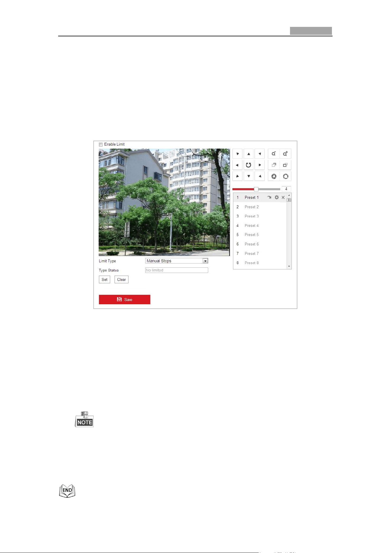
Network Speed Dome User Manual
73
5.4.2 Configuring PTZ Limits
Purpose:
The dome can be programmed to move within the configurable PTZ limits (left/right,
up/down).
Steps:
1. Enter the Limit Configuration interface:
Configuration > PTZ > Limit
Figure 5-30 Configure the PTZ Limit
2. Click the checkbox of Enable Limit and choose the limit type as manual stops or
scan stops.
Manual Stops:
When manual limit stops are set, you can operate the PTZ control panel
manually only in the limited surveillance area.
Scan Stops:
When scan limit stops are set, the random scan, frame scan, auto scan, tilt scan,
panorama scan is performed only in the limited surveillance area.
Manual Stops of Limit Type is prior to Scan Stops. When you set these two
limit types at the same time, Manual Stops is valid and Scan Stops is invalid.
3. Click the PTZ control buttons to find the left/right/up/down limit stops; you can
also call the defined presets and set them as the limits of the dome.
4. Click Set to save the limits or click Clear to clear the limits.
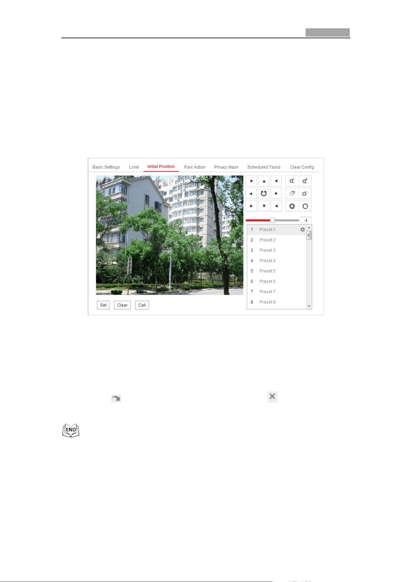
Network Speed Dome User Manual
74
5.4.3 Configuring Initial Position
Purpose:
The initial position is the origin of PTZ coordinates. It can be the factory default initial
position. You can also customize the initial position according to your own demand.
Customize an Initial Position:
Steps:
1. Enter the Initial Position Configuration interface:
Configuration > PTZ > Initial Position
Figure 5-31 PTZ Configuration
2. Click the PTZ control buttons to find a position as the initial position of the dome;
you can also call a defined preset and set it as the initial position of the dome.
3. Click Set to save the position.
Call/delete an Initial Position:
You can click to call the initial position. You can click to delete the initial
position and restore the factory default initial position.
5.4.4 Configuring Park Actions
Purpose:
This feature allows the dome to start a predefined park action (scan, preset, pattern
and etc.) automatically after a period of inactivity (park time).
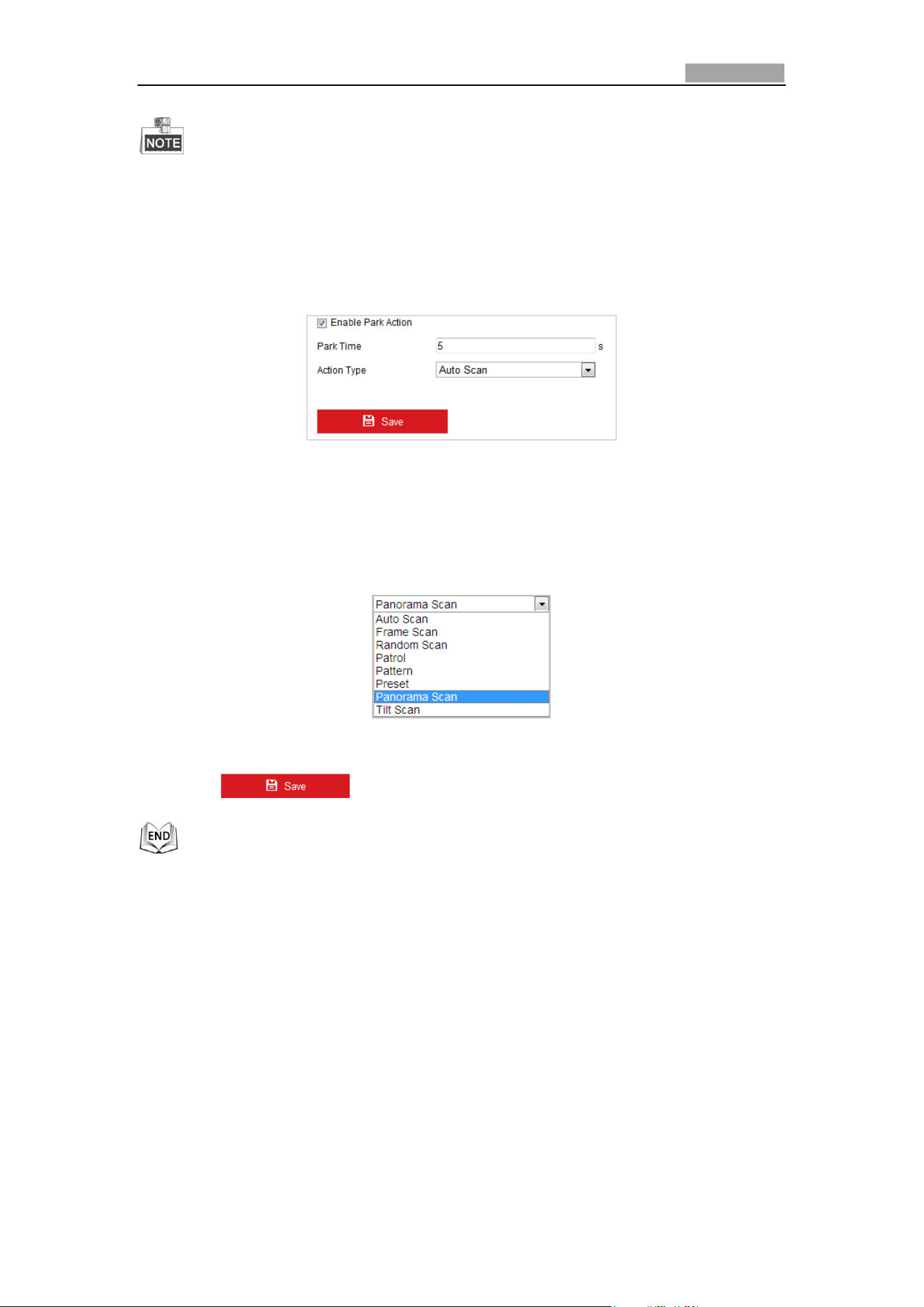
Network Speed Dome User Manual
75
Scheduled Tasks function is prior to Park Action function. When these two
functions are set at the same time, only the Scheduled Tasks function takes
effect.
Steps:
1. Enter the Park Action Settings interface:
Configuration > PTZ > Park Action
Figure 5-32 Set the Park Action
2. Check the checkbox of Enable Park Action.
3. Set the Park Time as the inactivity time of the dome before it starts the park
actions.
4. Choose Action Type the from the drop-down list.
Figure 5-33 Action Types
5. Click to save the settings.
5.4.5 Configuring Privacy Mask
Purpose:
Privacy mask enables you to cover certain areas on the live video to prevent certain
spots in the surveillance area from being live viewed and recorded.
Steps:
1. Enter the Privacy Mask Settings interface:
Configuration > PTZ > Privacy Mask
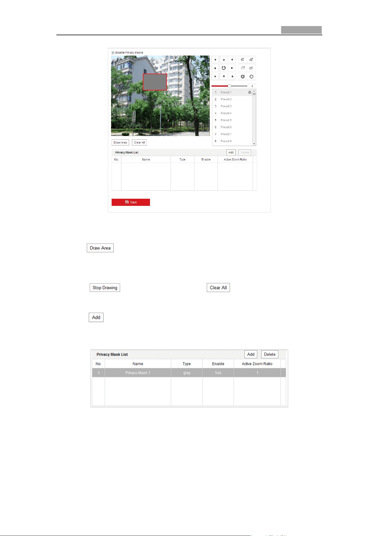
Network Speed Dome User Manual
76
Figure 5-34 Draw the Privacy Mask
2. Click the PTZ control buttons to find the area you want to set the privacy mask.
3. Click ; click and drag the mouse in the live video window to draw the
area.
You can drag the corners of the red rectangle area to draw a polygon mask.
4. Click to finish drawing or click to clear all of the areas you
set without saving them.
5. Click to save the privacy mask, and it will be listed in the Privacy Mask List
area; set the value of Active Zoom Ratio on your demand, and then the mask
will only appear when the zoom ratio is greater than the predefined value.
Figure 5-35 Privacy Mask List
6. you can also define the color of the masks.
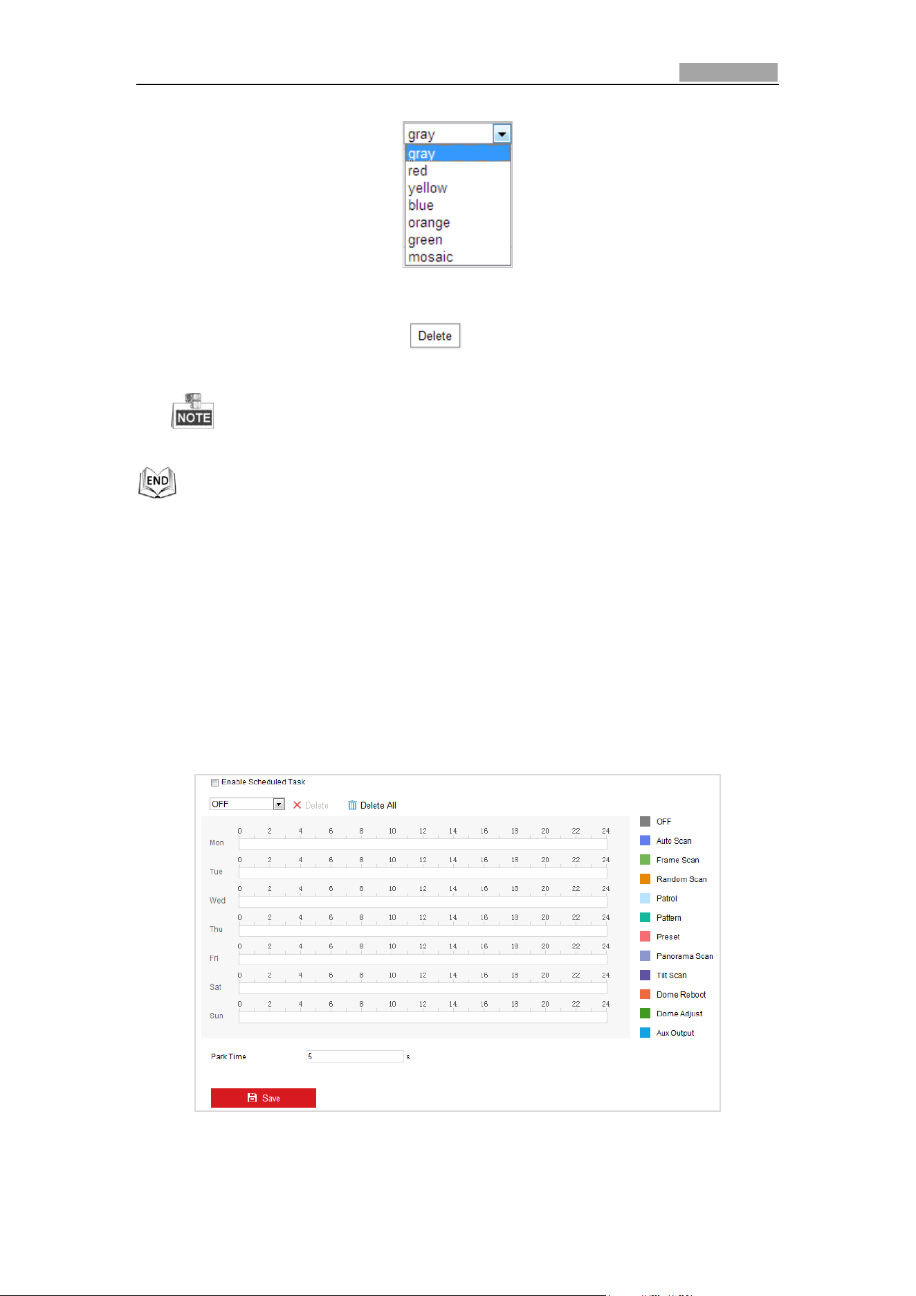
Network Speed Dome User Manual
77
Figure 5-36 Define Mask Color
7. You can select a mask and click to delete it from the list.
8. Check the checkbox of Enable Privacy Mask to enable this function.
You are allowed to draw up to 24 areas on the same image.
5.4.6 Configuring Scheduled Tasks
Purpose:
You can configure the network dome to perform a certain action automatically in a
user-defined time period.
Steps:
1. Enter the Scheduled Task Settings interface:
Configuration> PTZ > Scheduled Tasks
Figure 5-37 Configure Scheduled Tasks
2. Check the checkbox of Enable Scheduled Task.
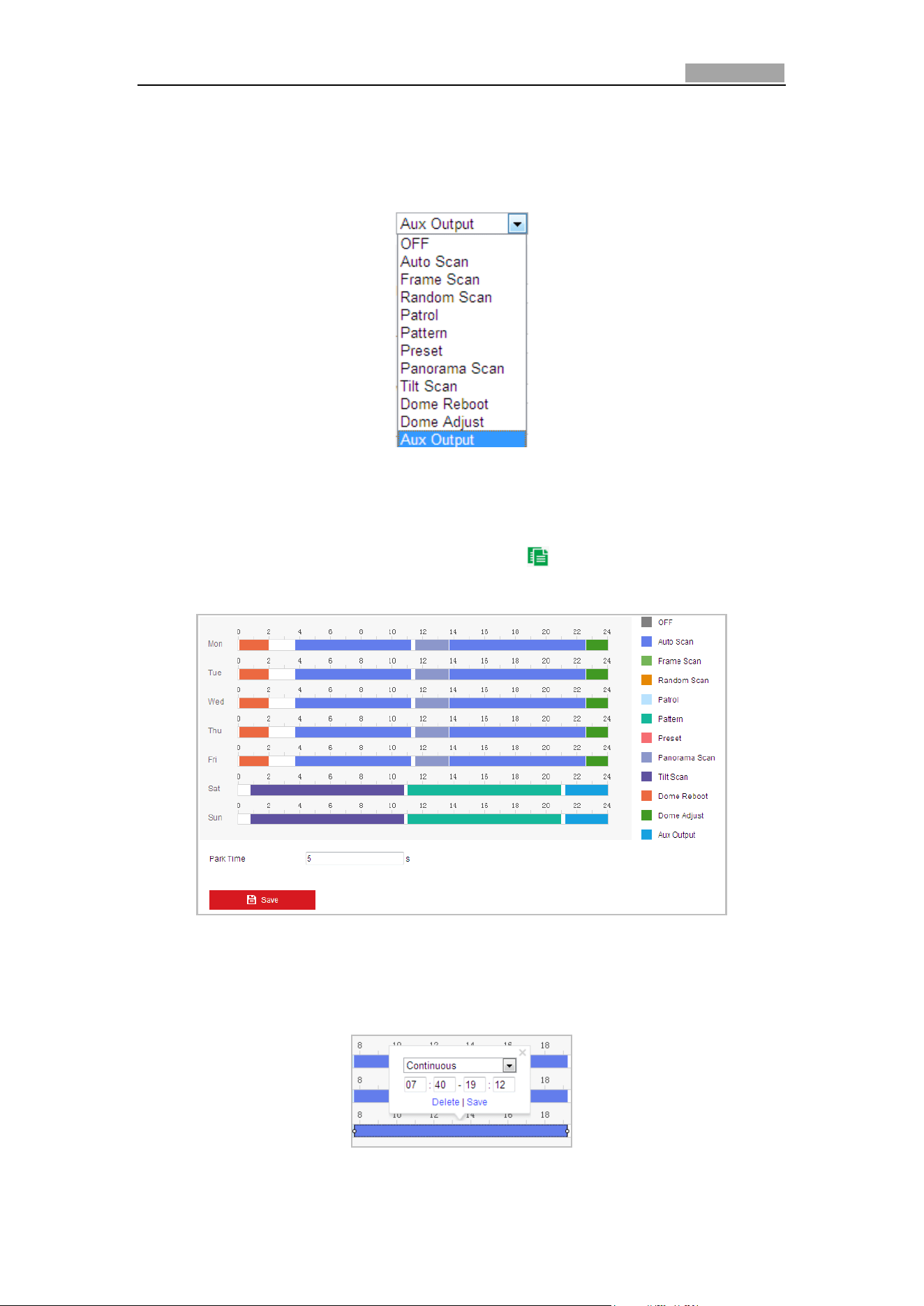
Network Speed Dome User Manual
78
3. Set the Park Time. You can set the park time (a period of inactivity) before the
dome starts the scheduled tasks.
4. Select the task type from the drop-down list. You can choose scan, preset,
pattern and etc.
Figure 5-38 Task Types
5. Select the timeline of a certain day, click and drag the left button of the mouse to
set the recording schedule (the start time and end time of the recording task).
6. After you set the scheduled task, you can click and copy the task to other
days (optional).
Figure 5-39 Edit the Schedule and Task Type
7. After setting the record schedule, you can click a record segment to display the
segment record settings interface to edit the segment record parameters.
(Optional)
Figure 5-40 Segment Record Settings
Network Speed Dome User Manual
79
The time of each task cannot be overlapped. Up to 10 tasks can be
configured for each day.
8. Click to save the settings.
5.4.7 Clearing PTZ Configurations
Purpose:
You can clear PTZ configurations in this interface, including all presets, patrols,
patterns, privacy masks, PTZ limits, scheduled tasks and park actions.
Steps:
1. Enter the Clearing Configuration interface:
Configuration > PTZ > Clear Config
2. Check the checkbox of the items you want to clear.
3. Click to clear the settings.
5.4.8 Configuring Smart Tracking
Purpose:
The speed dome tracks the moving objects automatically after you configure this
function.
Steps:
1. Enter the Smart Tracking Settings interface:
Configuration > PTZ > Smart Tracking
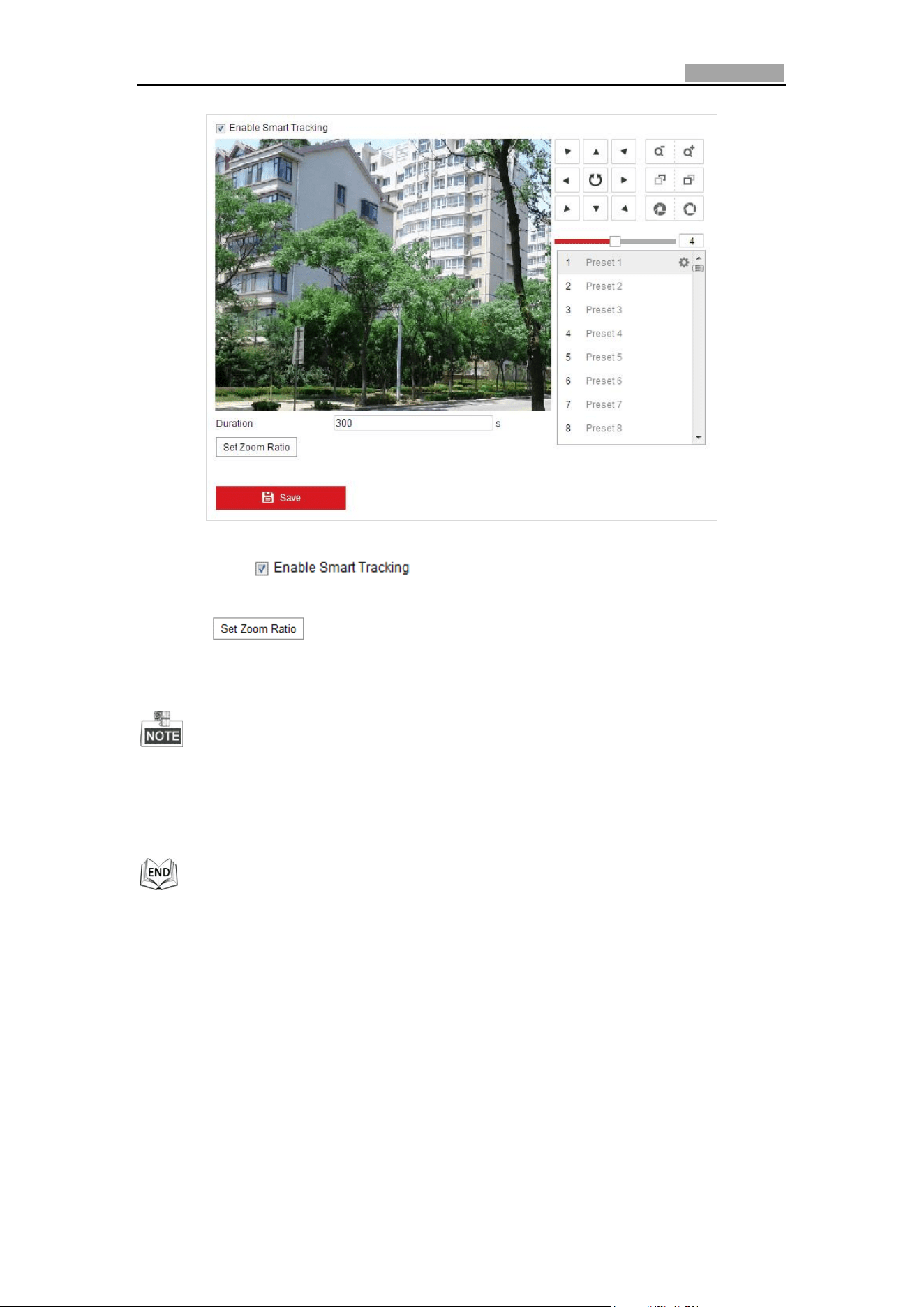
Network Speed Dome User Manual
80
Figure 5-41 Configure Smart Tracking
2. Check the check box to enable smart tracking function.
3. Click the PTZ buttons to select an object.
4. Click to set the current zoom ratio as the tracking zoom ratio.
5. Set the tracking duration. The speed dome stops tracking when the duration time
is up. The duration ranges from 0 to 300 seconds.
Setting the duration to 0 means that there’ no duration when speed dome
tracks.
Not all the speed dome models support this function. Please take the browser
interface of the actual product as standard.
5.4.9 Configuring PTZ Control Priority
Steps:
1. Get to the configuration interface:
Configuration > PTZ > Prioritize PTZ.
The speed dome can be controlled by network and RS-485 signals. You can set
the control priority of these two signals.
The operation of Operator is prior to that of User. When the Operator is
controlling the speed dome, the User cannot control it. When the Operator
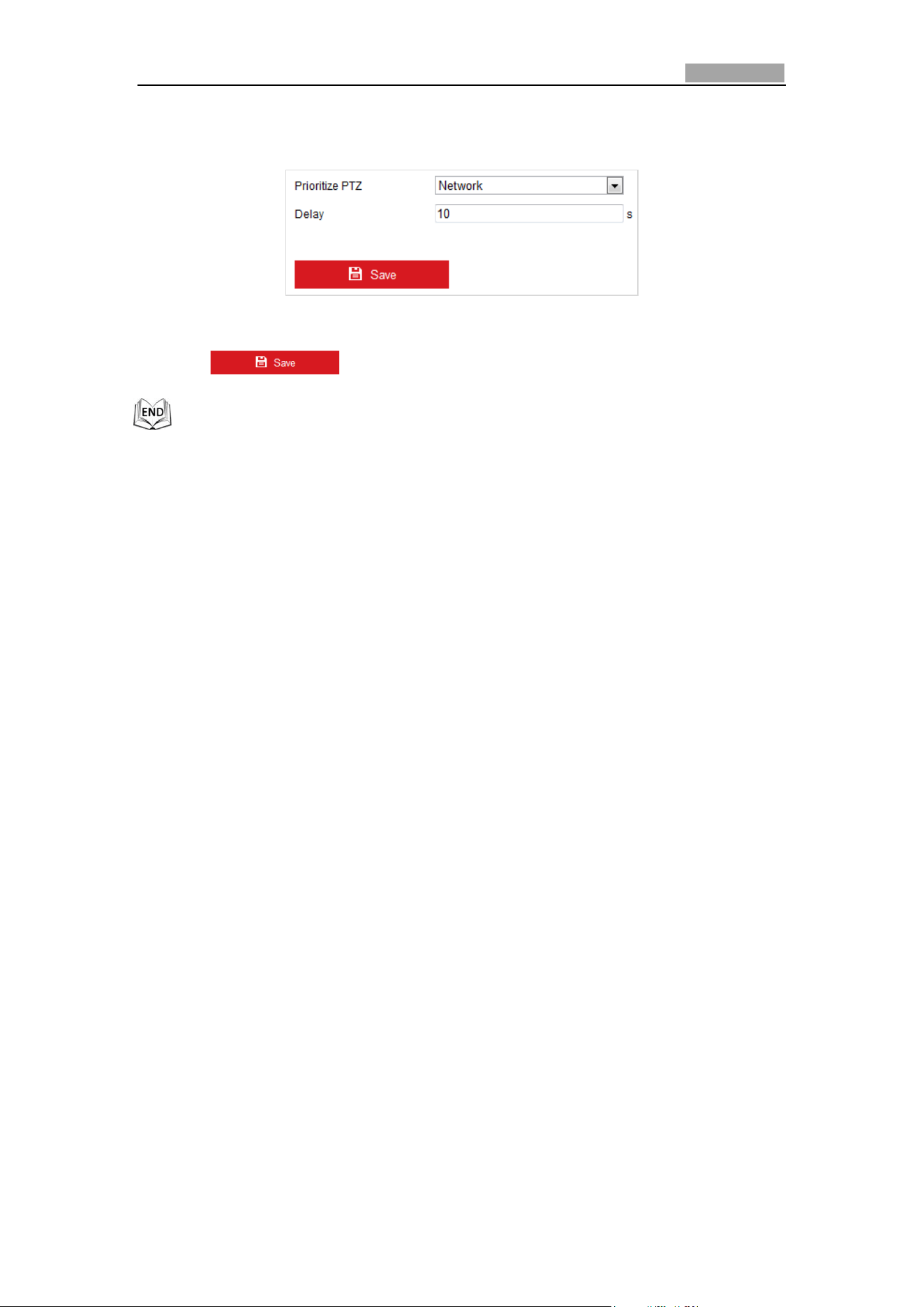
Network Speed Dome User Manual
81
finishes, the User can control the speed dome after the Delay time. The Delay
time can be set in Priority PTZ interface as shown follows.
Figure 5-42 PTZ Priority
2. Click to activate the settings.
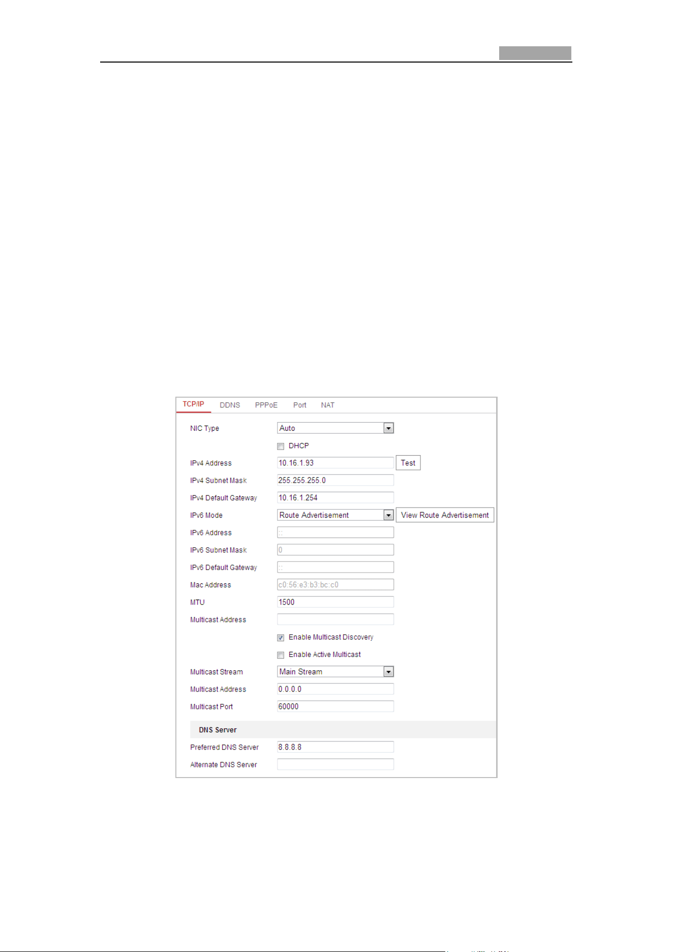
User Manual of Network Speed Dome
82
Chapter 6 Speed Dome Configuration
6.1 Configuring Network Settings
6.1.1 Basic Settings
Configuring TCP/IP Settings
Purpose:
TCP/IP settings must be properly configured before you operate the speed dome over
network. IPv4 and IPv6 are both supported.
Steps:
1. Enter TCP/IP Settings interface:
Configuration > Network > Basic Settings > TCP/IP
Figure 6-1 TCP/IP Settings
2. Configure the NIC settings, including the IPv4(IPv6) Address, IPv4(IPv6) Subnet
Mask and IPv4(IPv6) Default Gateway.
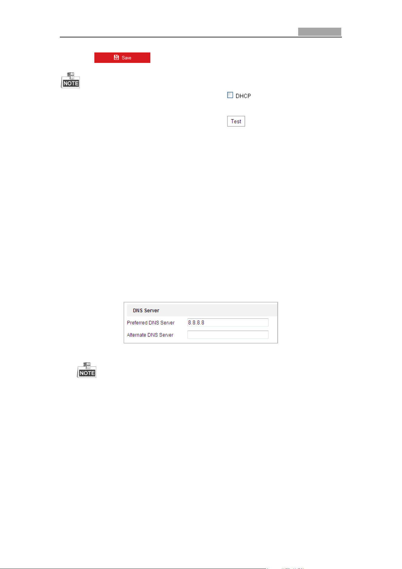
Network Speed Dome User Manual
83
3. Click to save the above settings.
If the DHCP server is available, you can check to automatically obtain
an IP address and other network settings from that server.
If the IP address is set manually, you can click to check whether the IP
address is already used to prevent the IP address confliction.
The valid value range of Maximum Transmission Unit (MTU) is 500 ~ 9676. The
default value is 1500.
The Multicast Discovery is enabled by default. You can disable this function if
multicast storm leads to abnormality of speed dome.
Enable Active Multicast and set the multicast stream type, multicast address,
and port No., the speed dome sends a stream to the multicast group address and
allows multiple clients to acquire the stream at the same time by requesting a
copy from the multicast group address.
Before utilizing this function, you have to enable the Multicast function of your
router and configure the gateway of the network speed dome.
If the DNS server settings are required for some applications (e.g., sending
email), you should properly configure the Preferred DNS Server and Alternate
DNS server.
Check the checkbox of Enable Multicast Discovery, and then the speed dome
can be detected by client software in the LAN.
Figure 6-2 DNS Server Settings
The router must support the route advertisement function if you select
Route Advertisement as the IPv6 mode.
Configuring DDNS Settings
Purpose:
If your speed dome is set to use PPPoE as its default network connection, you can
use the Dynamic DNS (DDNS) for network access.
Before you start:
Registration on the DDNS server is required before configuring the DDNS settings of
the speed dome.
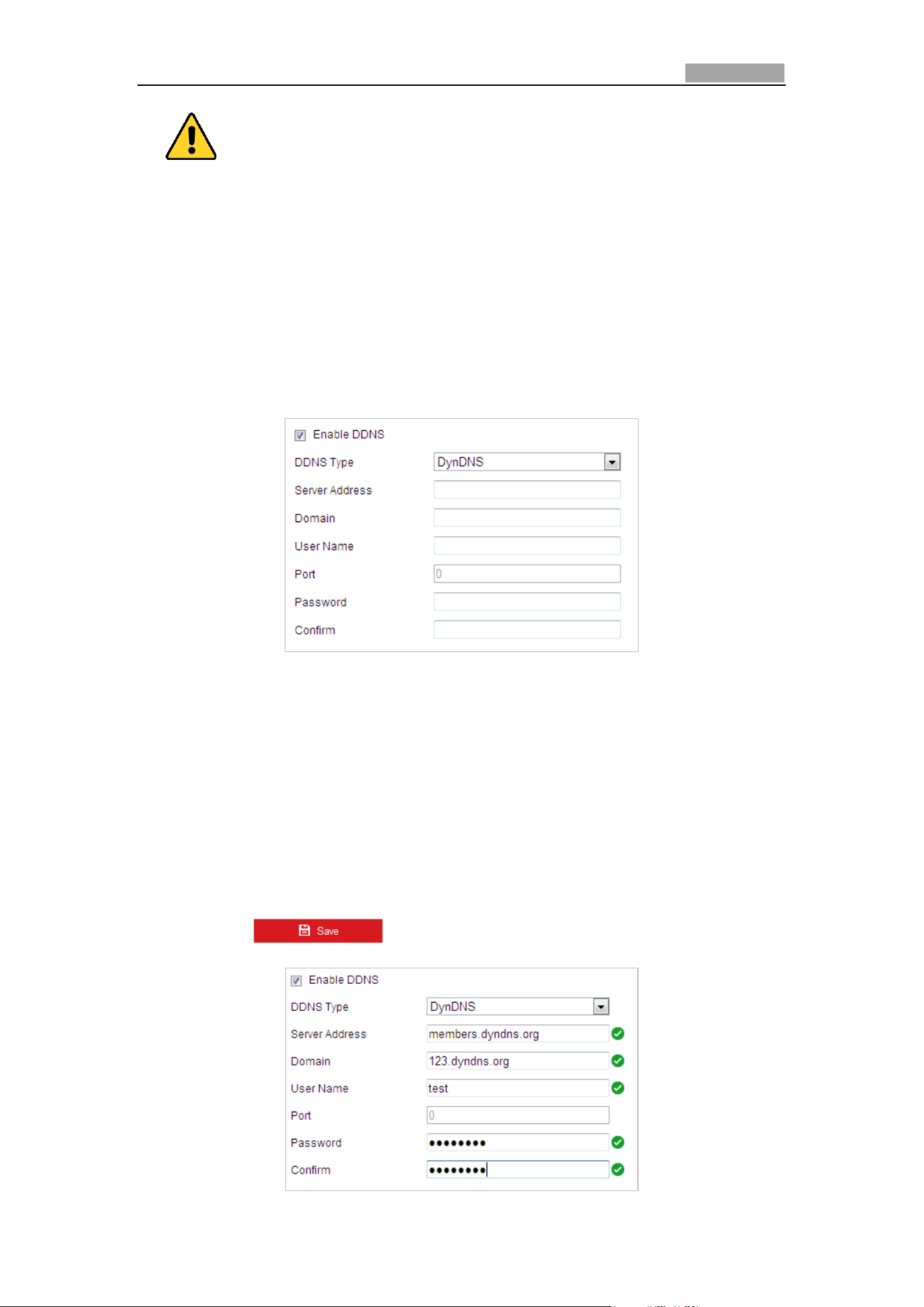
Network Speed Dome User Manual
84
For your privacy and to better protect your system against security risks, we
strongly recommend the use of strong passwords for all functions and network
devices. The password should be something of your own choosing (Using a
minimum of 8 characters, including at least three of the following categories:
upper case letters, lower case letters, numbers, and special characters.) in
order to increase the security of your product.
Proper configuration of all passwords and other security settings is the
responsibility of the installer and/or end-user.
Steps:
1. Enter the DDNS Settings interface:
Configuration > Network > Basic Settings > DDNS
Figure 6-3 DDNS Settings
2. Check the Enable DDNS checkbox to enable this feature.
3. Select DDNS Type. Three DDNS types are selectable: IPServer, HiDDNS, NO-IP
and DynDNS.
DynDNS:
Steps:
(1) Enter Server Address of DynDNS (e.g. members.dyndns.org).
(2) In the Domain text field, enter the domain name obtained from the DynDNS
website.
(3) Enter the Port of DynDNS server.
(4) Enter the User Name and Password registered on the DynDNS website.
(5) Click to save the settings.
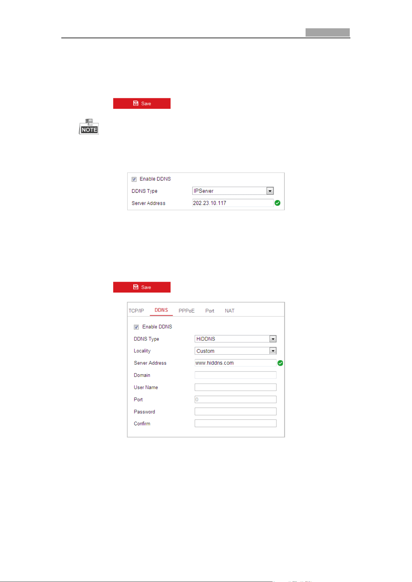
Network Speed Dome User Manual
85
Figure 6-4 DynDNS Settings
IPServer:
Steps:
(1) Enter the Server Address of the IPServer.
(2) Click to save the settings.
The Server Address should be entered with the static IP address of the
computer that runs the IP Server software. For the IP Server, you have to
apply a static IP, subnet mask, gateway and preferred DNS from the ISP.
Figure 6-5 IPServer Settings
HiDDNS:
Steps:
(1) Enter the Server Address: e.g. www.hiddns.com.
(2) Enter the Domain name of the camera. The domain is the same with the
device alias in the HiDDNS server.
(3) Click to save the settings.
Figure 6-6 HiDDNS Settings
NO-IP:
Steps:
(1) Enter Server Address of NO-IP.
(2) In the Domain text field, enter the domain name obtained from the NO-IP
website.
(3) Enter the Port of NO-IP server.
(4) Enter the User Name and Password registered on the NO-IP website.
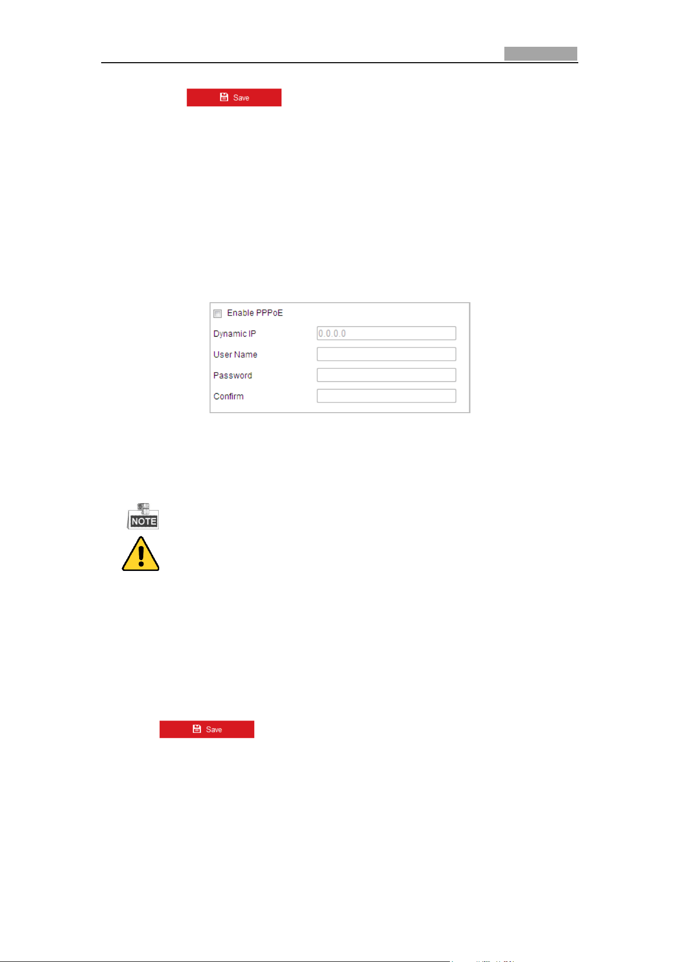
Network Speed Dome User Manual
86
(5) Click to save the settings.
Configuring PPPoE Settings
Purpose:
If you have no router but only a modem, you can use Point-to-Point Protocol over
Ethernet (PPPoE) function.
Steps:
1. Enter the PPPoE Settings interface:
Configuration > Network > Basic Settings > PPPoE
Figure 6-7 PPPoE Settings
2. Check the Enable PPPoE checkbox to enable this feature.
3. Enter User Name, Password, and Confirm password for PPPoE access.
The User Name and Password should be assigned by your ISP.
For your privacy and to better protect your system against security risks, we
strongly recommend the use of strong passwords for all functions and network
devices. The password should be something of your own choosing (Using a
minimum of 8 characters, including at least three of the following categories:
upper case letters, lower case letters, numbers, and special characters.) in
order to increase the security of your product.
Proper configuration of all passwords and other security settings is the
responsibility of the installer and/or end-user.
4. Click to save and exit the interface.
Configuring Port Settings
Purpose:
If there is a router and you want to access the speed dome through Wide Area
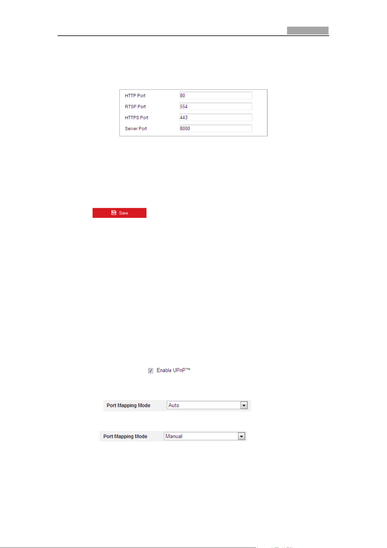
Network Speed Dome User Manual
87
Network (WAN), you need to forward the 3 ports for the speed dome.
Steps:
1. Enter the Port Settings interface:
Configuration > Network > Basic Settings > Port
Figure 6-8 Port Settings
2. Set the HTTP port, RTSP port, HTTPS port and port of the speed dome.
HTTP Port: The default port number is 80.
RTSP Port: The default port number is 554.
HTTPS Port: The default port number is 443.
Server Port: The default port number is 8000.
3. Click to save the settings.
Configuring NAT (Network Address Translation) Settings
Purpose:
Universal Plug and Play (UPnP™) is a networking architecture that provides
compatibility among networking equipment, software and other hardware devices.
The UPnP protocol allows devices to connect seamlessly and to simplify the
implementation of networks in the house and corporate environments.
With the function enabled, you don’t need to configure the port mapping for each
port, and the camera is connected to the Wide Area Network via the router.
Steps:
1. Enter the NAT settings interface by
Configuration > Network > Basic Settings > NAT
2. Check the checkbox of to enable the UPnP™ function.
3. Set the port mapping mode:
To port mapping with the default port numbers:
Choose
To port mapping with the customized port numbers:
Choose
And you can customize the value of the port No. by yourself.
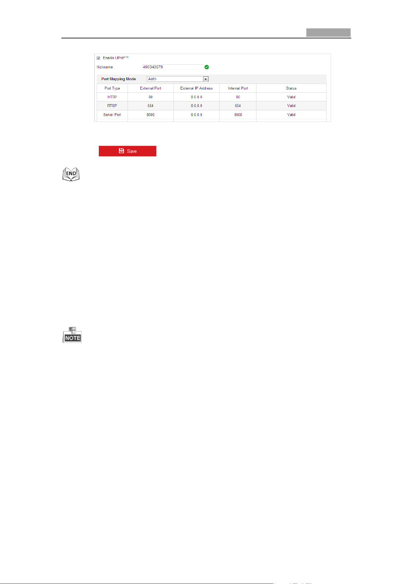
Network Speed Dome User Manual
88
Figure 6-9 Configure the Port No.
4. Click to save the settings.
6.1.2 Advanced Settings
Configuring SNMP Settings
Purpose:
You can use SNMP to get speed dome status and parameters related information.
Before you start:
Before setting the SNMP, please use the SNMP software and manage to receive the
speed dome information via SNMP port. By setting the Trap Address, the speed dome
can send the alarm event and exception messages to the surveillance center.
The SNMP version you select should be the same as that of the SNMP software.
Steps:
1. Enter the SNMP Settings interface:
Configuration > Network > Advanced Settings > SNMP
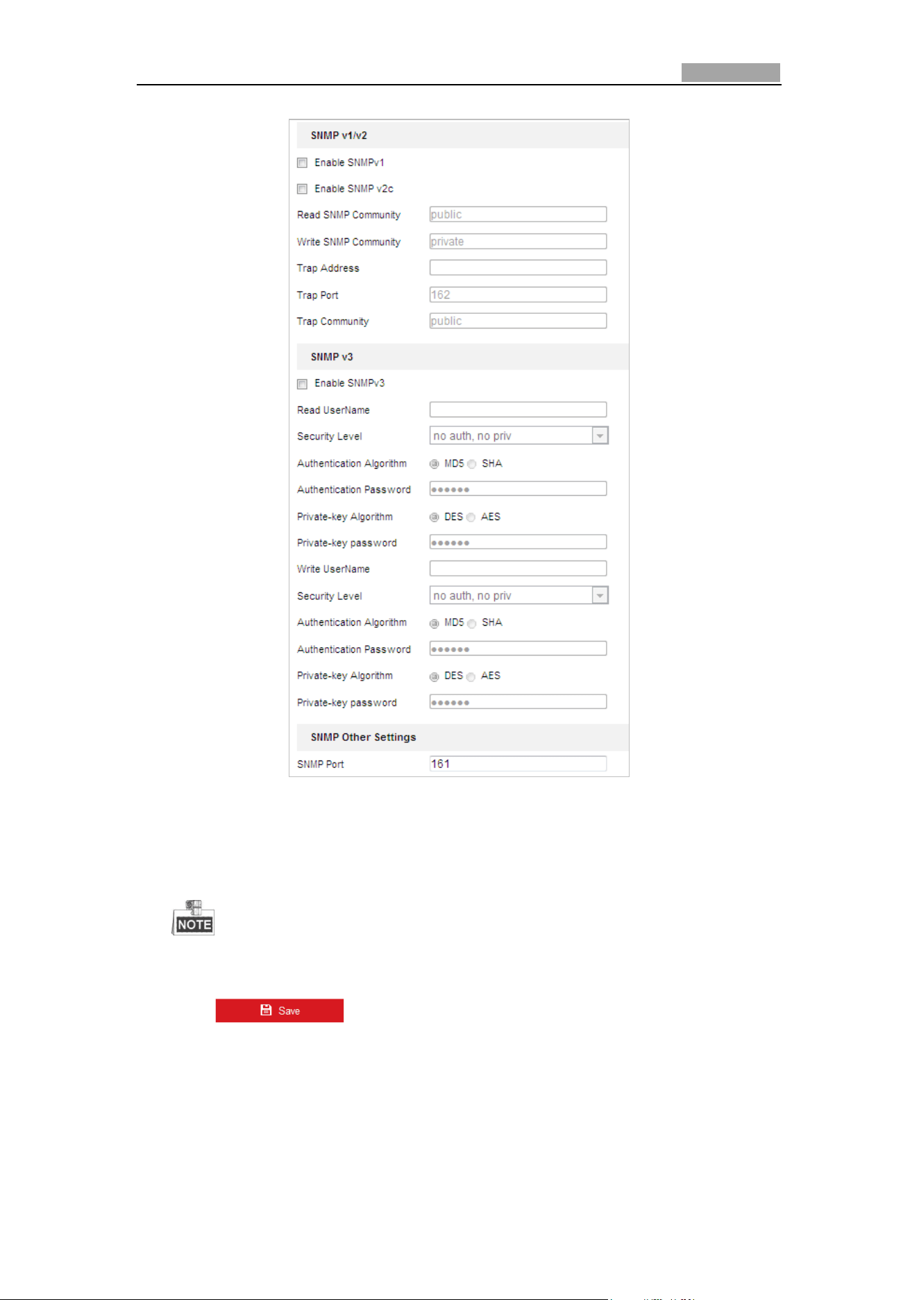
Network Speed Dome User Manual
89
Figure 6-10 SNMP Settings
2. Check the corresponding version checkbox (Enable SNMP v1, Enable SNMP v2c,
Enable SNMP v3) to enable the feature.
3. Configure the SNMP settings.
The configuration of the SNMP software should be the same as the settings
you configure here.
4. Click to save and finish the settings.
Configuring FTP Settings
Purpose:
You can set a FTP server and configure the following parameters for uploading
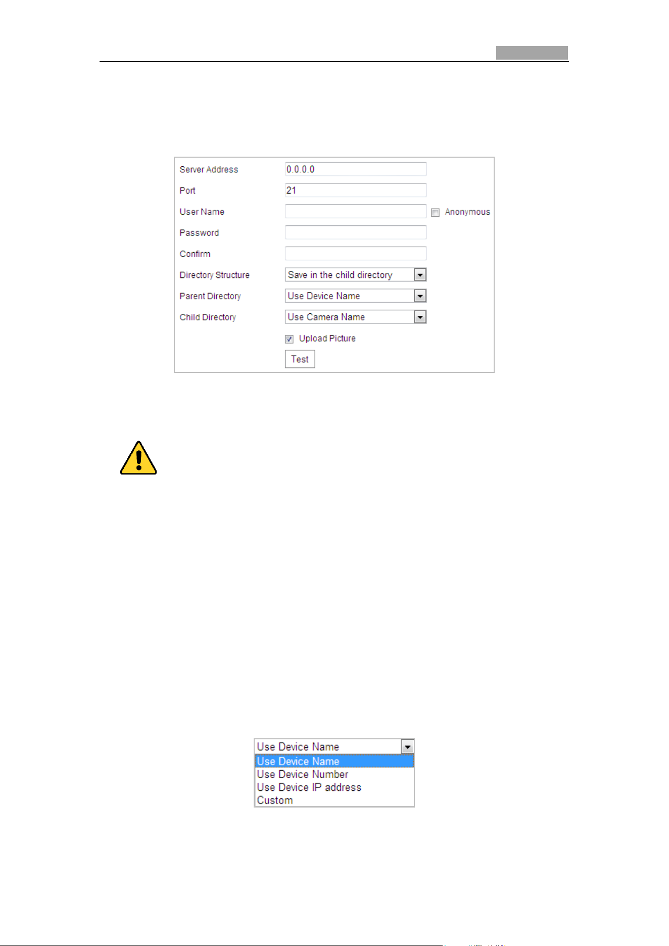
Network Speed Dome User Manual
90
captured pictures.
Steps:
1. Enter the FTP Settings interface:
Configuration > Network > Advanced Settings > FTP
Figure 6-11 FTP Settings
2. Configure the FTP settings, including server address, port, user name, password,
directory, and upload type.
For your privacy and to better protect your system against security risks, we
strongly recommend the use of strong passwords for all functions and network
devices. The password should be something of your own choosing (Using a
minimum of 8 characters, including at least three of the following categories:
upper case letters, lower case letters, numbers, and special characters.) in
order to increase the security of your product.
Proper configuration of all passwords and other security settings is the
responsibility of the installer and/or end-user.
The server address supports both the domain name and IP address formats.
Setting the directory in FTP server for saving files:
In the Directory Structure field, you can select the root directory, parent
directory and child directory.
Root directory: The files will be saved in the root of FTP server.
Parent directory: The files will be saved in a folder in FTP server. The
name of folder can be defined as shown in following Figure 6-12.
Figure 6-12 Parent Directory
Child directory: It is a sub-folder which can be created in the parent
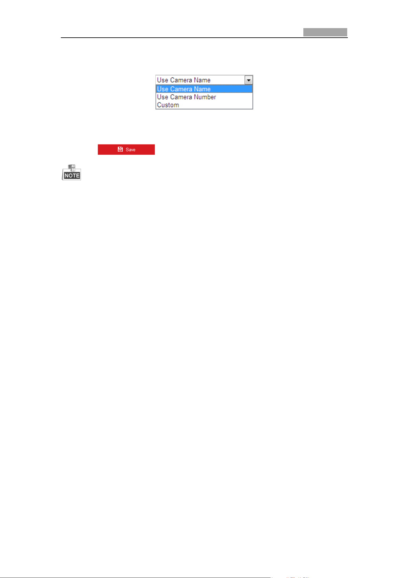
Network Speed Dome User Manual
91
directory. The files will be saved in a sub-folder in FTP server. The name of
folder can be defined as shown in following Figure 6-13.
Figure 6-13 Child Directory
Upload type: To enable uploading the captured picture to the FTP server.
3. Click to save the settings.
If you want to upload the captured pictures to FTP server, you also have to
enable the continuous snapshot or event-triggered snapshot in Snapshot
interface. For detailed information, please refer to the Section 5.1.2
Configuring .
Configuring Email Settings
Purpose:
The system can be configured to send an Email notification to all designated
receivers if an alarm event is detected, e.g., motion detection event, video loss,
tamper-proof, etc.
Before you start:
Please configure the DNS Server settings under Configuration> Network > Basic
Settings > TCP/IP before using the Email function.
Steps:
1. Enter the Email Settings interface:
Configuration> Network > Advanced Settings > Email
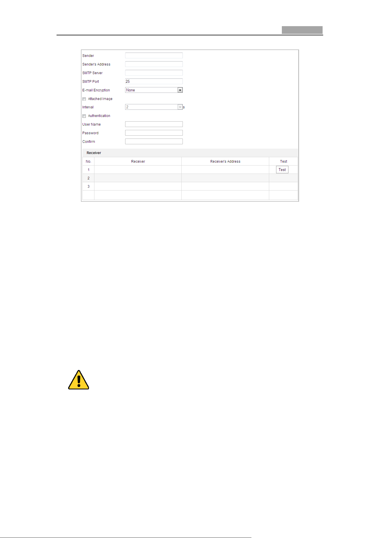
Network Speed Dome User Manual
92
Figure 6-14 Email Settings
2. Configure the following settings:
Sender: The name of the email sender.
Sender’s Address: The email address of the sender.
SMTP Server: The SMTP Server IP address or host name (e.g.,
smtp.263xmail.com).
SMTP Port: The SMTP port. The default TCP/IP port for SMTP is 25.
Enable SSL: Check the checkbox to enable SSL if it is required by the SMTP
server.
Attached Image: Check the checkbox of Attached Image if you want to send
emails with attached alarm images.
Interval: The interval refers to the time between two actions of sending attached
pictures.
Authentication (optional): If your email server requires authentication, check
this checkbox to use authentication to log in to this server and enter the login
user name and password.
For your privacy and to better protect your system against security risks, we
strongly recommend the use of strong passwords for all functions and network
devices. The password should be something of your own choosing (Using a
minimum of 8 characters, including at least three of the following categories:
upper case letters, lower case letters, numbers, and special characters.) in
order to increase the security of your product.
Proper configuration of all passwords and other security settings is the
responsibility of the installer and/or end-user.
Receiver: Select the receiver to which the email is sent. Up to 2 receivers can be
configured.
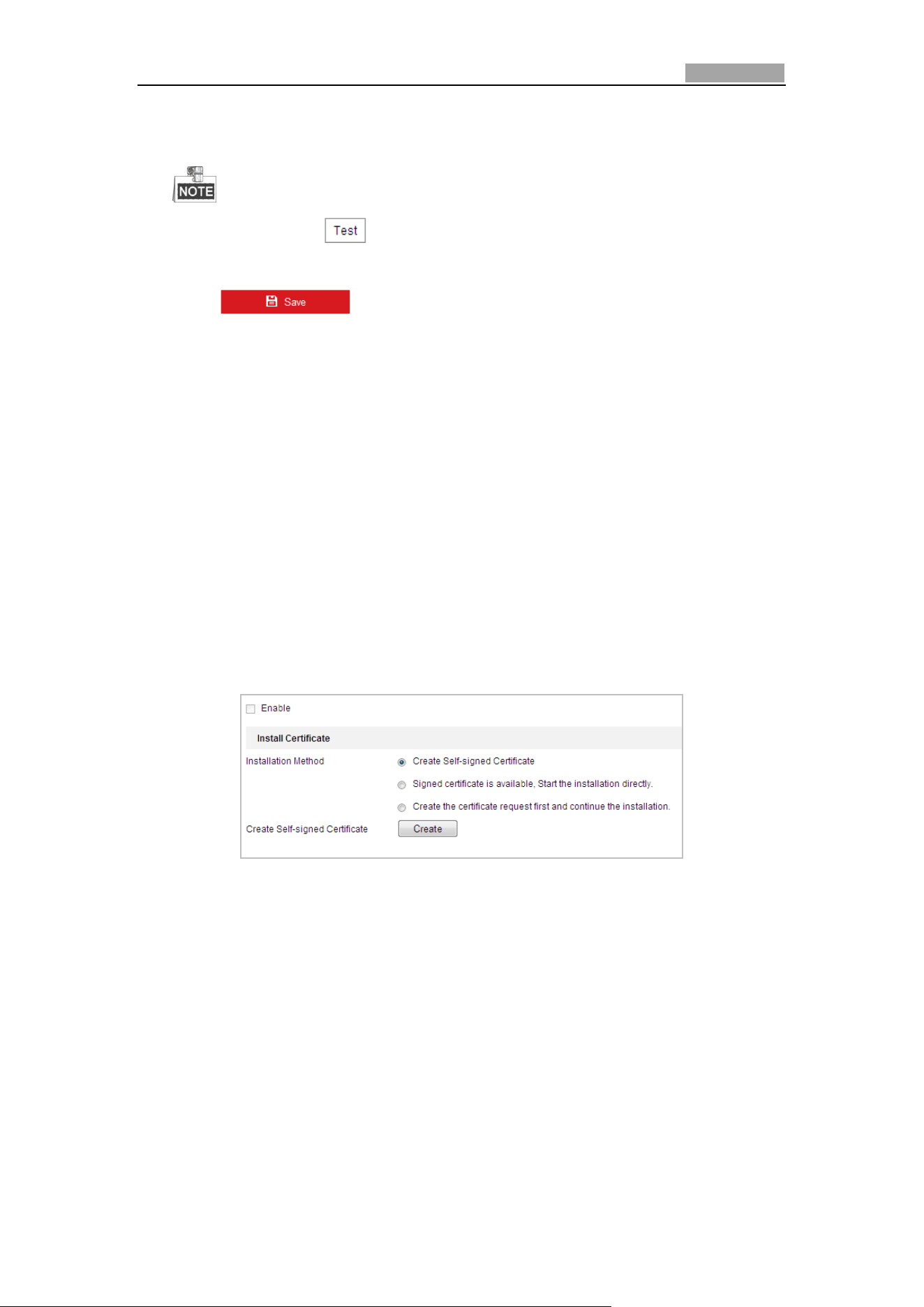
Network Speed Dome User Manual
93
Receiver: The name of the user to be notified.
Receiver’s Address: The email address of user to be notified.
You can click to check whether the setting is invalid after the
required parameters are configured.
3. Click to save the settings.
Configuring HTTPS Settings
Purpose:
HTTPS provides authentication of the web site and associated web server that one is
communicating with, which protects against Man-in-the-middle attacks. Perform the
following steps to set the port number of https.
Example:
If you set the port number as 443 and the IP address is 192.168.1.64, you may access
the device by inputting https://192.168.1.64:443 via the web browser.
Steps:
1. Enter the HTTPS settings interface.
Configuration > Network > Advanced Settings > HTTPS
2. Create the self-signed certificate or authorized certificate.
Figure 6-15 Create Certificate
OPTION 1: Create the self-signed certificate
1) Select Create Self-signed Certificate.
2) Click the Create button to create the following dialog box.
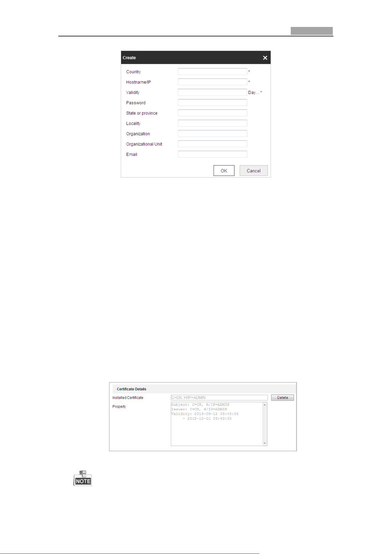
Network Speed Dome User Manual
94
Figure 6-16 Create Self-signed Certificate
3) Enter the country, host name/IP, validity and other information.
4) Click OK to save the settings.
OPTION 2: Start the installation when signed certificate is available.
1) Select Signed certificate is available, Start the installation directly.
2) Click the Browse button to upload the available certificate.
3) Click Install button to install the certificate.
4) Click OK to save the settings.
OPTION 3: Create certificate request first and continue the installation.
1) Select Create certificate request first and continue the installation.
2) Click the Create button to create the certificate request, and fulfill the
required information.
3) Download the certificate request and submit it to the trusted certificate
authority for signature.
4) After receiving the signed valid certificate, import the certificate to the
device.
5) Click OK to save the settings.
3. There will be the certificate information after you successfully create and install
the certificate.
Figure 6-17 Installed Certificate Property
You can click configure the HTTPS port No. on your demand; refer to Section
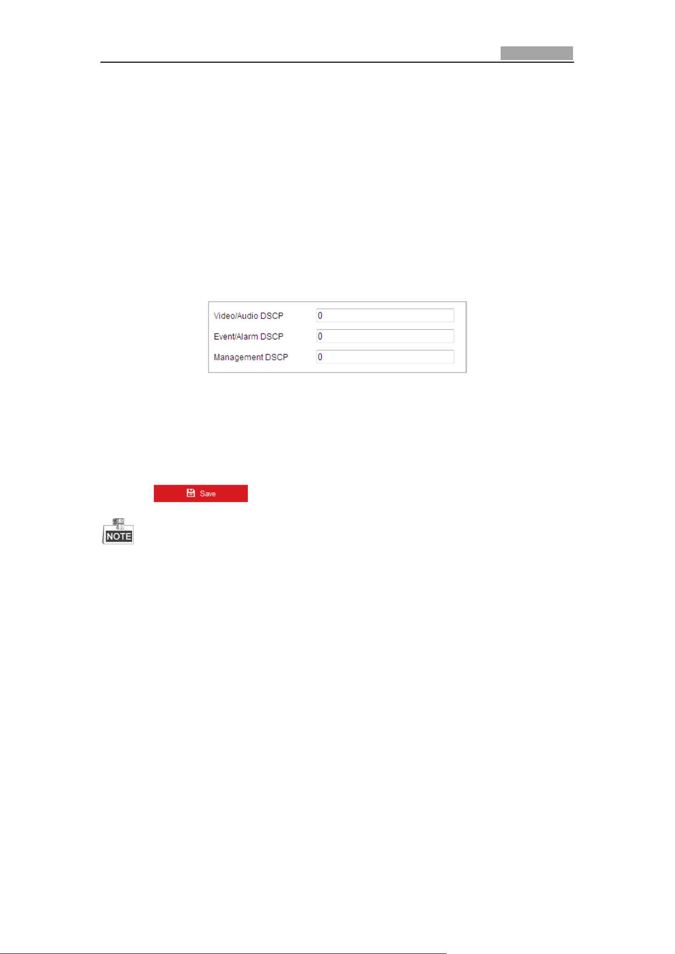
Network Speed Dome User Manual
95
0 Configuring Port Settings for details.
4. Check the checkbox of Enable HTTPS and click the Save button.
Configuring QoS Settings
Purpose:
QoS (Quality of Service) can help solve the network delay and network congestion by
configuring the priority of data sending.
Steps:
1. Enter the QoS Settings interface:
Configuration > Network >Advanced Settings > QoS
Figure 6-18 QoS Settings
2. Configure the QoS settings, including video / audio DSCP, event / alarm DSCP and
Management DSCP.
The valid DSCP value ranges from 0 to 63. The DSCP value is bigger, the priority is
higher.
3. Click to save the settings.
Make sure that you enable the QoS function of your network device (such as a
router).
It will ask for a reboot for the settings to take effect.
Configuring 802.1X Settings
Purpose:
The speed dome supports IEEE 802.1X standard.
IEEE 802.1X is a port-based network access control. It enhances the security level of
the LAN. When devices connect to this network with IEEE 802.1X standard, the
authentication is needed. If the authentication fails, the devices don’t connect to the
network.
The protected LAN with 802.1X standard is shown as follows:
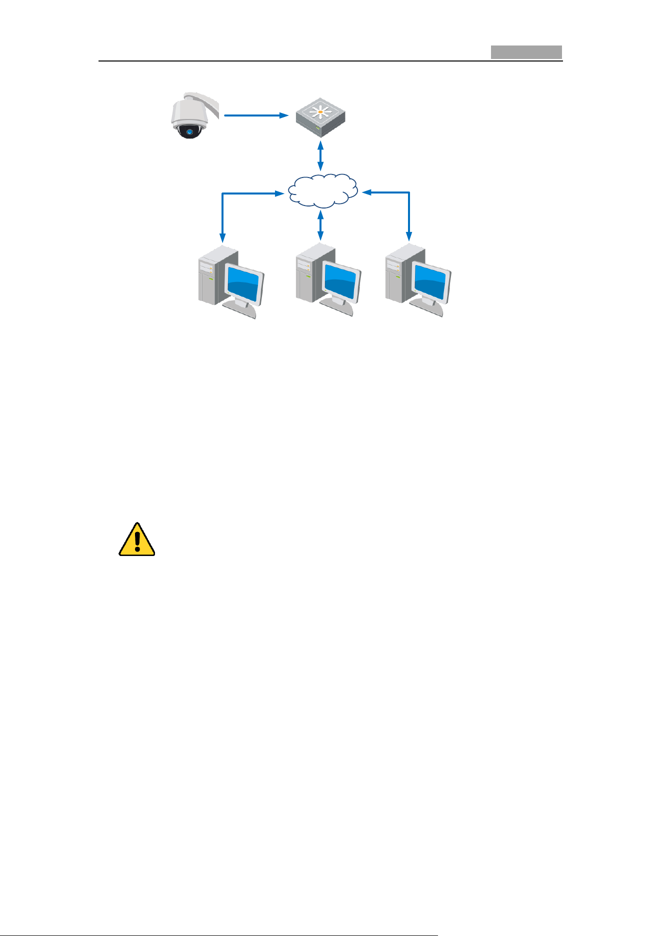
Network Speed Dome User Manual
96
Speed Dome
PC
Network Switch
Internet
PC
RADIUS Server
Authenticator
Authentication
Server
Figure 6-19 Protected LAN
Before connecting the Network Camera to the protected LAN, please apply a
digital certificate from a Certificate Authority.
The network camera requests access to the protected LAN via the
authenticator (a switch).
The switch forwards the identity and password to the authentication server
(RADIUS server).
The switch forwards the certificate of authentication server to the network
camera.
If all the information is validated, the switch allows the network access to
the protected network.
For your privacy and to better protect your system against security risks, we
strongly recommend the use of strong passwords for all functions and network
devices. The password should be something of your own choosing (Using a
minimum of 8 characters, including at least three of the following categories:
upper case letters, lower case letters, numbers, and special characters.) in
order to increase the security of your product.
Proper configuration of all passwords and other security settings is the
responsibility of the installer and/or end-user.
Steps:
1. Connect the network camera to your PC directly with a network cable.
2. Enter the 802.1X Settings interface:
Configuration > Network > Advanced Settings > 802.1X
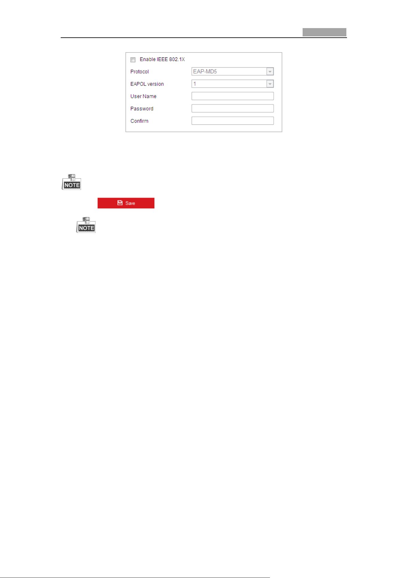
Network Speed Dome User Manual
97
Figure 6-20 802.1X Settings
3. Check the Enable IEEE 802.1X checkbox to enable it.
4. Configure the 802.1X settings, including user name and password.
The EAP-MD5 version must be identical with that of the router or the switch.
5. Click to finish the settings.
The camera reboots when you save the settings.
6. After the configuration, connect the camera to the protected network.
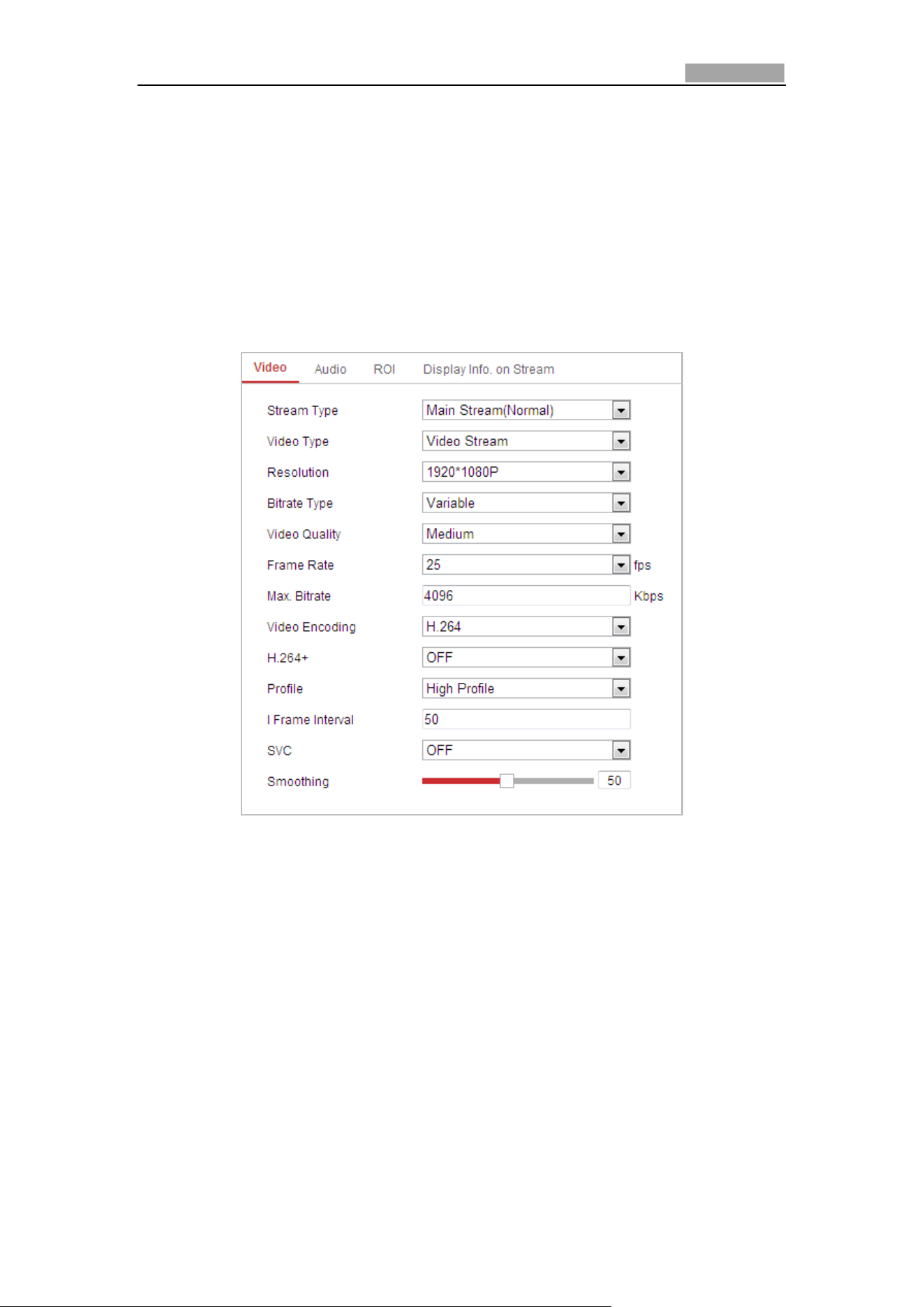
User Manual of Network Speed Dome
98
6.2 Configuring Video and Audio Settings
6.2.1 Configuring Video Settings
Steps:
1. Enter the Video Settings interface:
Configuration > Video/Audio > Video
Figure 6-21 Configure Video Settings
2. Select the Stream Type of the speed dome to main stream (normal) or
sub-stream.
The main stream is usually for recording and live viewing with good bandwidth,
and the sub-stream can be used for live viewing when the bandwidth is limited.
Refer to the Section 4.2 Configuring Local Parameters for switching the main
stream and sub-stream for live viewing.
3. You can customize the following parameters for the selected main stream or
sub-stream:
Video Type:
Select the stream type to video stream, or video & audio composite stream. The
audio signal will be recorded only when the Video Type is Video&Audio.
Resolution:
Select the resolution of the video output.
Network Speed Dome User Manual
99
Bitrate Type:
Select the bitrate type to constant or variable.
Video Quality:
When bitrate type is selected as Variable, 6 levels of video quality are selectable.
Frame Rate:
The frame rate is to describe the frequency at which the video stream is updated
and it is measured by frames per second (fps). A higher frame rate is
advantageous when there is movement in the video stream, as it maintains image
quality throughout.
Max. Bitrate:
Set the max. bitrate to 32~16384 Kbps. The higher value corresponds to the
higher video quality, and the higher bandwidth is required as well.
Video Encoding:
The Video Encoding standard can be set.
Profile:
You can set the profile level to High Profile, Main Profile or Basic Profile.
I Frame Interval:
Set the I-Frame interval from 1 to 400.
SVC:
SVC is a video encoding technology. It extracts frames from the original video and
sends these frames to a video recorder which also supports SVC function when
the network bandwidth is insufficient.
Smoothing:
Drag the to adjust the value of video smoothing on
your demand.
H.264+: If you set the main stream as the stream type, and H.264 as the video
coding, you can see H.264+ is available. H.264+ is an advanced compression
coding technology. By enabling H.264+, you can estimate the HDD consumption by
its maximum average bitrate. Compared to H.264, H.264+ reduces storage by up
to 50% with the same maximum bitrate in most scenes. You need to reboot the
camera if you want to turn on or turn off the H.264+.
Upgrade your video player to the latest version if live view or playback does not
work properly due to compatibility.
When H.264+ is enabled, functions such as, Third Stream, SVC, Main Stream
Smoothing, Target Cropping, High Frame Rate, WDR, HLC, 4000*3000 resolution,
3840*2160 resolution, are not supported.
With H.264+ enabled, the parameters such as profile, I frame interval, and SVC
are greyed out if the bitrate type is variable.
H.264+ can spontaneously adjust the bitrate distribution according the
requirements of the actual scene in order to realize the set maximum average
bitrate in the long term. The camera needs at least 3 days to adapt to its
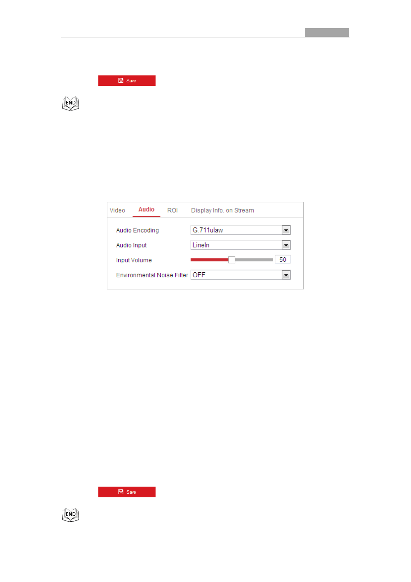
Network Speed Dome User Manual
100
monitoring scene.
H.264+ function is only supported by certain devices.
4. Click to save the settings.
6.2.2 Configuring Audio Settings
Steps:
1. Enter the Audio Settings interface
Configuration > Video/Audio > Audio
Figure 6-22 Audio Settings
2. Configure the following settings.
Audio Encoding: G.722.1, G.711ulaw, G.711alaw, MP2L2, ACC, PCM and G.726
selectable.
Audio Stream Bitrate: When the Audio Encoding is selected as MP2L2, you can
configure the Audio Stream Bitrate in the dropdown list. The greater the value is,
the better the audio quality will be.
Sampling Rate: When the Audio Encoding is selected as MP2L2 or PCM, you can
configure the Sampling Rate in the dropdown list. The greater the value is, the
better the audio quality will be.
Audio Input: When an intercom is connected to the speed dome, you need to
set this option to LineIn. When a microphone is connected to the speed dome,
you need to set this option to MicIn.
Input Volume: Slid the bar to turn up/down the volume. The value ranges from 0
to 100.
Environmental Noise Filter: When the monitoring environment is very noisy, you
can enable this function to reduce part of the noise.
3. Click to save the settings.
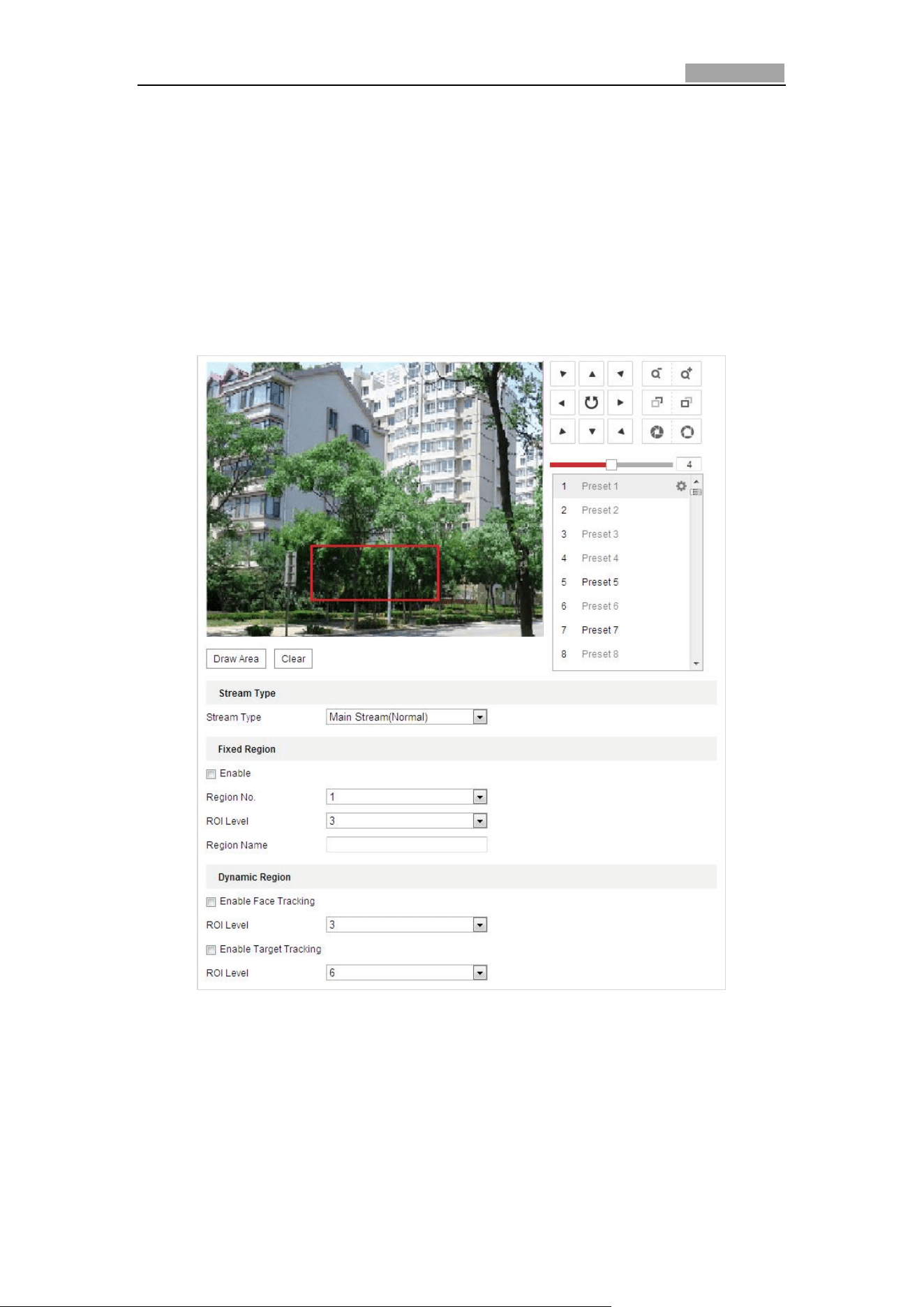
Network Speed Dome User Manual
101
6.2.3 Configuring ROI Settings
Before you start:
ROI (Region of Interest) encoding is used to enhance the quality of images which are
specified in advance.
Enter the ROI Settings interface:
Configuration >Video/Audio > ROI
Figure 6-23 Region of Interest
Stream Type:
You can set the ROI function for main stream or substream. Select a stream type and
then configure the ROI settings.
Fixed Region: The fixed region encoding is the ROI encoding for the manually
configured area. And you can choose the Image Quality Enhancing level for ROI
encoding, and you can also name the ROI area.
Network Speed Dome User Manual
102
Steps:
1. Select a Region No..
2. Check the checkbox of Enable under Fixed Region.
3. Select the region from the dropdown list for ROI settings. There are four fixed
regions selectable.
4. Click the button, and then click-and-drag the mouse to draw the
region of interest on the live video.
5. Adjust the ROI level from 1 to 6. The higher the value, the better image quality
in the red frame.
6. Enter a Region Name and click Save to save the settings.
Dynamic Region: The device can automatically calculate the region with motion.
Set the Image Quality Enhancing level for ROI encoding.
Steps:
1. Check the checkboxes of desired functions, including Target Tracking and Face
Tracking.
Target Tracking: When a smart event is detected, e.g. line crossing detection,
the object which trigger the pre-defined rule will be automatically tracked, and
the image quality of the tracking target will be increased.
Face Tracking: When the face detection is triggered, the image quality of the
face will be increased.
To enable target tracking function, you should enable the smart tracking
function, refer to section 5.4.8 Configuring Smart Tracking.
To enable face tracking function, the face detection function should be
supported and enabled.
2. Respectively set the ROI level. The higher the value, the better image quality in
the red frame.
3. Click Save to save the settings.
6.2.4 Dual-VCA Settings
Steps:
1. Check the checkbox to enable the function of Dual-VCA which can be used
cooperatively with NVR to implement dual-VCA retrieval during playback.
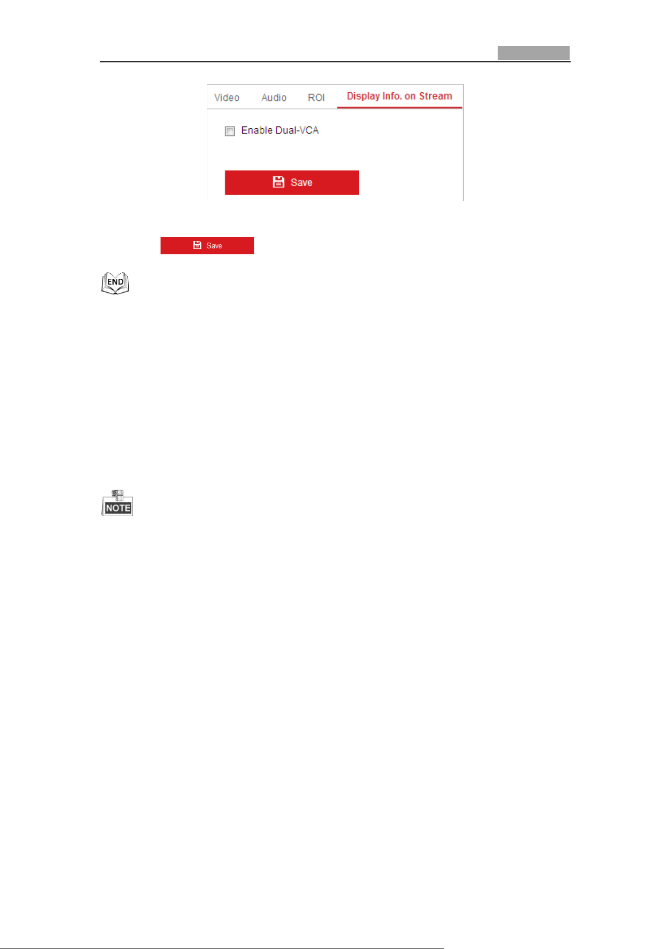
Network Speed Dome User Manual
103
Figure 6-24 Enable Dual-VCA
2. Click to save the settings.
6.3 Configuring Image Settings
6.3.1 Configuring Display Settings
Purpose:
You can set the image quality of the speed dome, including brightness, contrast,
saturation, sharpness, etc.
The parameters in Display Settings interface vary depending on the models of
speed dome.
You can double click the live view to enter full screen mode and double click it
again to exit.
Steps:
1. Enter the Display Settings interface:
Configuration > Image> Display Settings
2. You can select the Mounting Scenario in the dropdown list with different
predefined image parameters.
3. Set the image parameters of the speed dome.
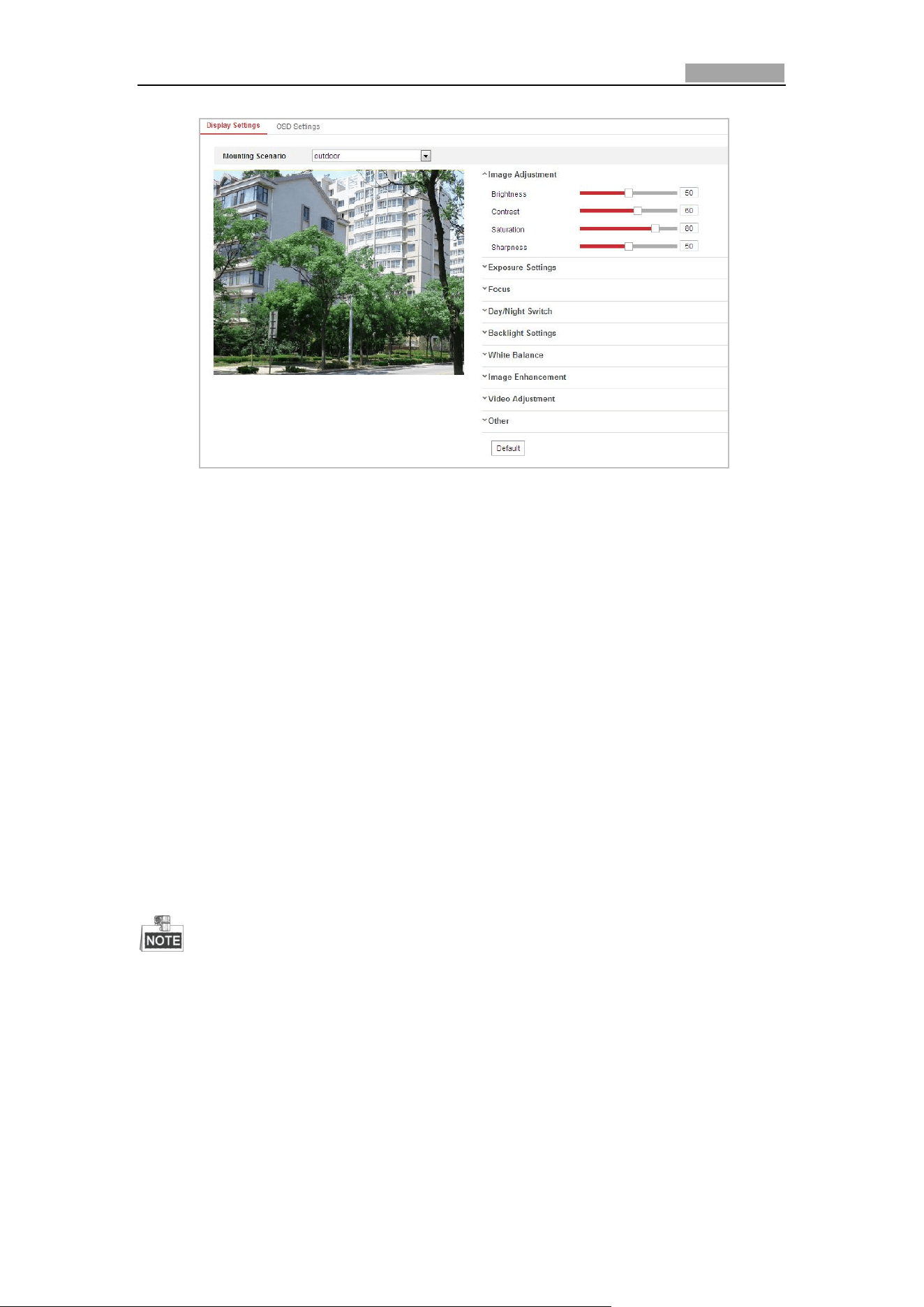
Network Speed Dome User Manual
104
Figure 6-25 Display Settings
Image Adjustment
Brightness
This feature is used to adjust brightness of the image. The value ranges from 0 to
100.
Contrast
This feature enhances the difference in color and light between parts of an image.
The value ranges from 0 to 100.
Saturation
This feature is used to adjust color saturation of the image. The value ranges from 0
to 100.
Sharpness
Sharpness function enhances the detail of the image by sharpening the edges in the
image. The value ranges from 0 to 100.
This function varies depending on the models of speed dome.
Exposure Settings
Exposure Mode
The Exposure Mode can be set to Auto, Iris Priority, Shutter Priority, and
Manual.
Auto:
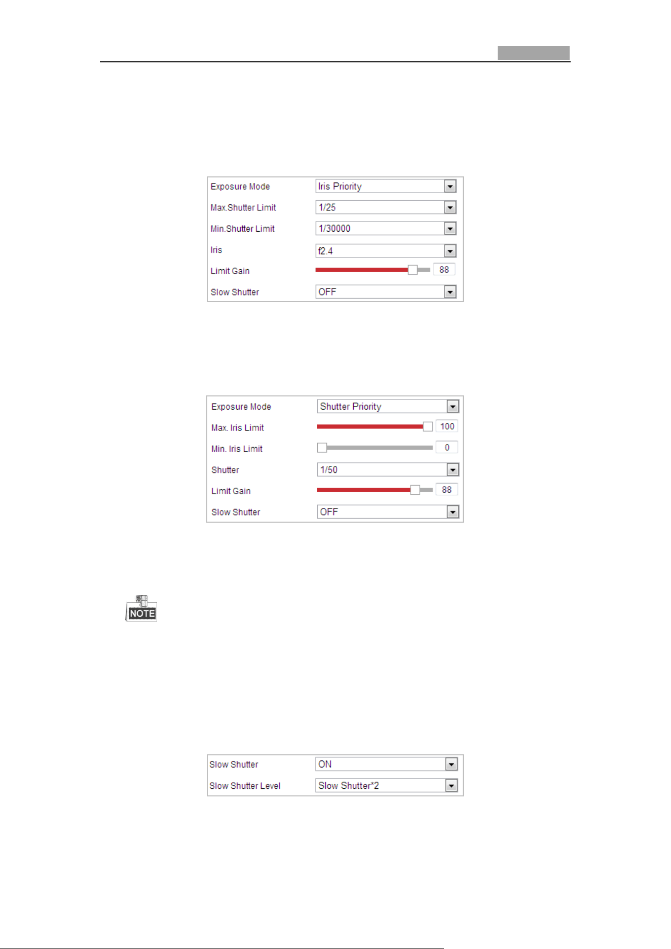
Network Speed Dome User Manual
105
The iris, shutter and gain values will be adjusted automatically according to the
brightness of the environment.
Iris Priority:
The value of iris needs to be adjusted manually. The shutter and gain values will
be adjusted automatically according to the brightness of the environment.
Figure 6-26 Manual Iris
Shutter Priority:
The value of shutter needs to be adjusted manually. The iris and gain values will
be adjusted automatically according to the brightness of the environment.
Figure 6-27 Manual Shutter
Manual:
In Manual mode, you can adjust the values of Gain, Shutter, Iris manually.
This function varies depending on the models of speed dome.
Limit Gain
This feature is used to adjust gain of the image. The value ranges from 0 to 100.
Slow Shutter
This function can be used in underexposure condition. It lengthens the shutter time
to ensure full exposure. The slow shutter value can be set to Slow Shutter*2, *4, *6,
*12, *16, *24 and *32.
Figure 6-28 Slow Shutter
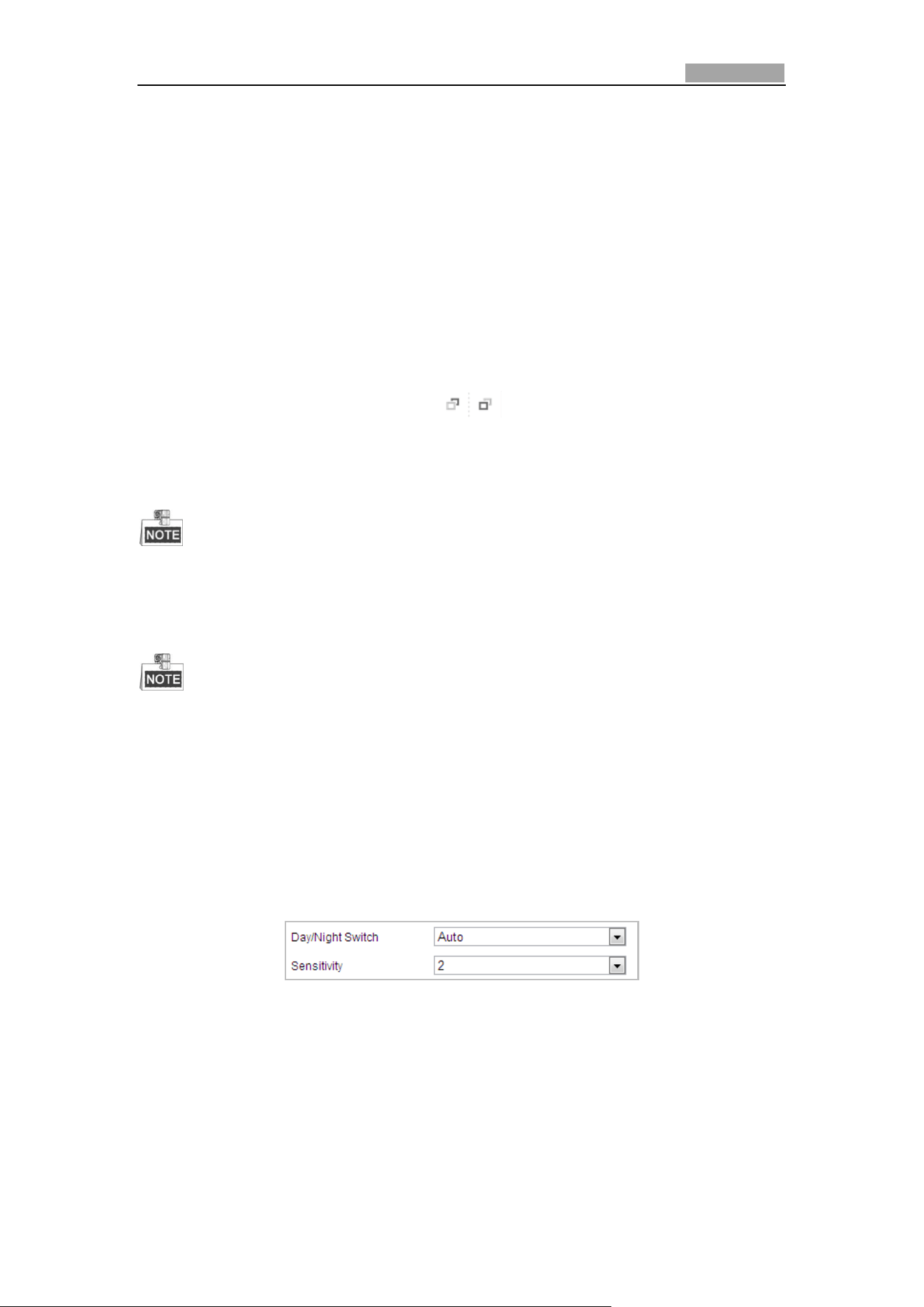
Network Speed Dome User Manual
106
Focus Settings
Focus Mode
The Focus Mode can be set to Auto, Manual, Semi-auto.
Auto:
The speed dome focuses automatically at any time according to objects in the
scene.
Semi-auto:
The speed dome focuses automatically only once after panning, tilting and
zooming.
Manual:
In Manual mode, you need to use on the control panel to focus
manually.
Min. Focus Distance
This function is used to limit the minimum focus distance.
The minimum focus value varies depending on the models of speed dome.
Day/Night Switch
The IR light related function introduced below is supported by IR speed domes
only.
Day/Night Switch
The Day/Night Switch mode can be set to Auto, Day, Night, and
Scheduled-Switch.
Auto:
In Auto mode, the day mode and night mode can switch automatically
according to the light condition of environment. The switching sensitivity can
be set to Low, Normal, High.
Figure 6-29 Auto Mode Sensitivity
Day:
In Day mode, the speed dome displays color image. It is used for normal
lighting conditions.
Night:
In Night mode, the image is black and white. Night mode can increase the
sensitivity in low light conditions.
Schedule
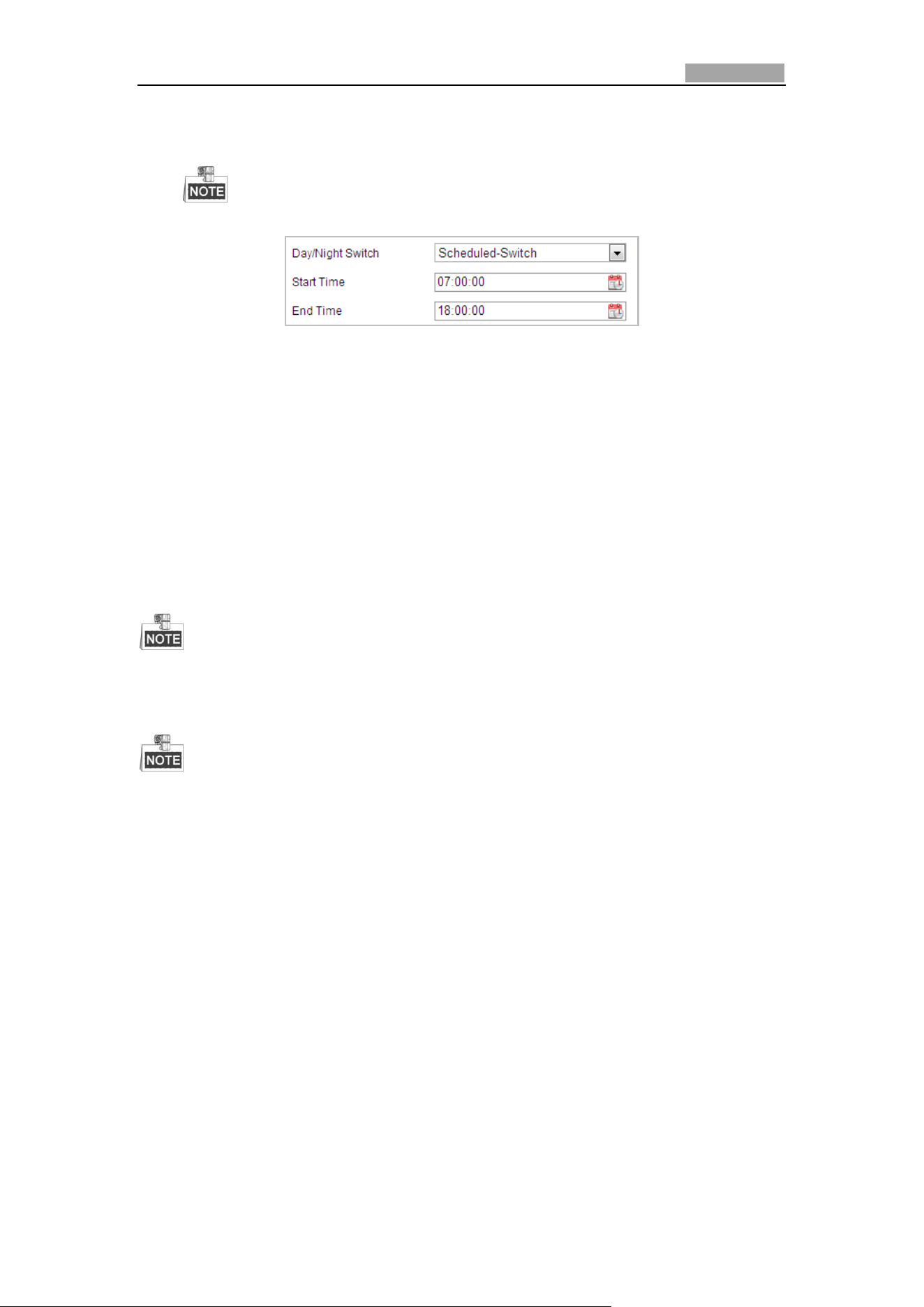
Network Speed Dome User Manual
107
In Schedule mode, you can set the time schedule for day mode as shown in
Figure 6-30. The rest time out of the schedule is for night mode.
This function varies depending on the models of speed dome.
Figure 6-30 Day Night Schedule
Smart Supplement Light
If the light supplement is on and the image center is overexposure, you can enable
this function.
IR Light Mode
IR light mode can be set to Auto and Manual.
Auto: The brightness of the infrared light will be adjusted automatically. IR
Light Sensitivity value ranges from 0 to 100. Trigger Mode can be set to
Camera or Photosensitive.
Manual: you need to adjust the brightness value of infrared light manually.
Brightness Limit value ranges from 0 to 100.
The IR related functions are supported by the IR speed dome only.
For detailed parameters configuration of IR light, you can enter the OSD menu by
calling the special preset 95.
When the IR Light Mode is auto, the day/night mode is adjusted automatically
according to the IR Light Mode. Manually setting the day/night mode is invalid.
When the IR Light Mode is manual and the Brightness Limit is 0, you can set the
day/night mode manually.
When the IR Light Mode is manual and the Brightness Limit is not 0, the night
mode is set as the default mode. Manually setting the day/night mode is invalid.
Backlight Settings
BLC (Back Light Compensation)
If there’s a bright backlight, the subject in front of the backlight appears silhouetted
or dark. Enabling BLC (back light compensation) function can correct the exposure of
the subject. But the backlight environment is washed out to white.
WDR (Wide Dynamic Range)
The wide dynamic range (WDR) function helps the camera provide clear images even
under back light circumstances. When there are both very bright and very dark areas
simultaneously in the field of view, WDR balances the brightness level of the whole
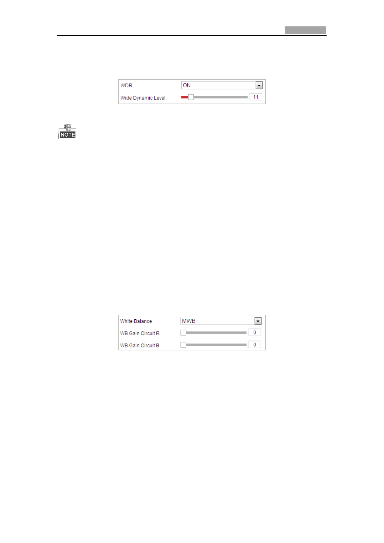
Network Speed Dome User Manual
108
image and provide clear images with details.
You can enable or disable the WDR function as shown in Figure 6-31. The wide
dynamic level ranges from 0 to 100.
Figure 6-31 WDR
This function varies depending on the models of speed dome.
HLC
HLC (High Light Compensation) makes the camera identify and suppress the strong
light sources that usually flare across a scene. This makes it possible to see the detail
of the image that would normally be hidden.
White Balance
The White Balance mode can be set to Auto, MWB, Outdoor, Indoor, Fluorescent
Lamp, Sodium Lamp and Auto-Track.
Auto:
In Auto mode, the camera retains color balance automatically according to the
current color temperature.
MWB:
In MWB (Manual White Balance) mode, you can adjust the color temperature
manually to meet your own demand as shown in Figure 6-32.
Figure 6-32 Manual White Balance
Outdoor
You can select this mode when the speed dome is installed in outdoor environment.
Indoor
You can select this mode when the speed dome is installed in indoor environment.
Fluorescent Lamp
You can select this mode when there are fluorescent lamps installed near the speed
dome.
Sodium Lamp
You can select this mode when there are sodium lamps installed near the speed
dome.
Auto-Track
In Auto-Track mode, white balance is continuously being adjusted in real-time
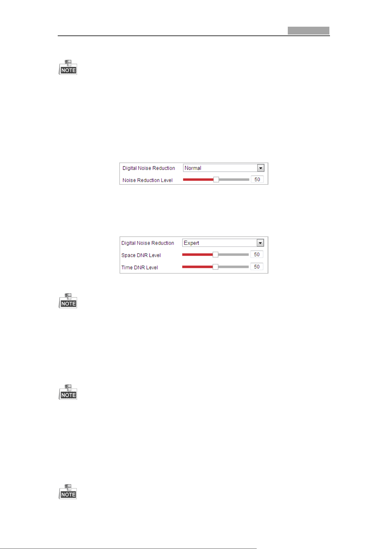
Network Speed Dome User Manual
109
according to the color temperature of the scene illumination.
This function varies depending on the models of speed dome.
Image Enhancement
Digital Noise Reduction
The digital noise reduce function processes the noise in the video signal.
You can set Digital Noise Reduction function to Normal and adjust the Noise
Reduction Level as shown in Figure 6-33. The level ranges from 0 to 100.
Figure 6-33 Normal Mode
If you are a professional technician, you can set it to Expert Mode then adjust Space
DNR Level and Time DNR Level.
Figure 6-34 Expert Mode
This function varies depending on the models of speed dome.
Defog Mode
When there is fog in the image, you can enable this function to get clear image.
EIS (Electronic Image Stabilization)
The live view image would be trembled and dim when the camera is shocked slightly
in some monitoring conditions. And the electronic image stabilization (EIS) function
is used to overcome this problem to ensure a steady and clear image.
This function varies depending on the models of speed dome.
Video Adjustment
Mirror
If you turn the MIRROR function on, the image will be flipped. It is like the image in
the mirror. The flip direction can be set to OFF, LEFT/RIGHT, UP/DOWN or CENTER.
Network Speed Dome User Manual
110
This function varies depending on the models of speed dome.
Video Standard
You can set the Video Standard to 50 Hz (PAL) or 60 Hz (NTSC) according to the video
system in your country.
This function varies depending on the models of speed dome.
Capture Mode:
The Capture Mode can be selected from the list.
Other
Lens Initialization
The lens operates the movements for initialization when you check the checkbox of
Lens Initialization.
Zoom Limit
You can set Zoom Limit value to limit the maximum value of zooming. The value can
be selected from the list.
This function varies depending on the models of speed dome.
Local Output
You can enable or disable the video output through the CVBS interface on your
demand.
6.3.2 Configuring OSD Settings
Purpose:
The speed dome supports following on screen displays:
Zoom: Identifies the amount of magnification.
Direction: Displays panning and tilting direction, with the format of PXXX TXXX. The
XXX following P indicates the degrees in pan direction, while the XXX following T
indicates the degrees in tilt position.
Time: Supports for time display.
Preset Title: Identifies preset being called.
Camera Name: Identifies the name of speed dome.
You can customize the on screen display of time.
Steps:
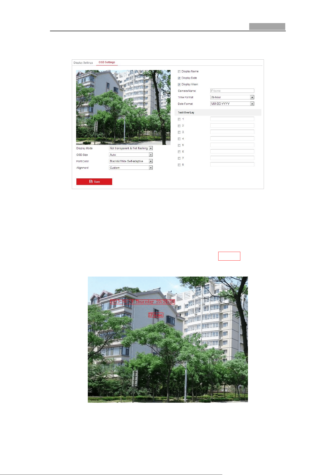
Network Speed Dome User Manual
111
1. Enter the OSD Settings interface:
Configuration > Image > OSD Settings
Figure 6-35 OSD Settings
2. Check the corresponding checkbox to select the display of speed dome name,
date or week if required.
3. Edit the speed dome name in the text field of Camera Name.
4. Select from the drop-down list to set the time format, date format and display
mode.
5. You can use the mouse to click and drag the text frame IPDome in the live view
window to adjust the OSD position.
Figure 6-36 Adjust OSD Location
6. The font color can also be customized, select the Custom in the drop down list
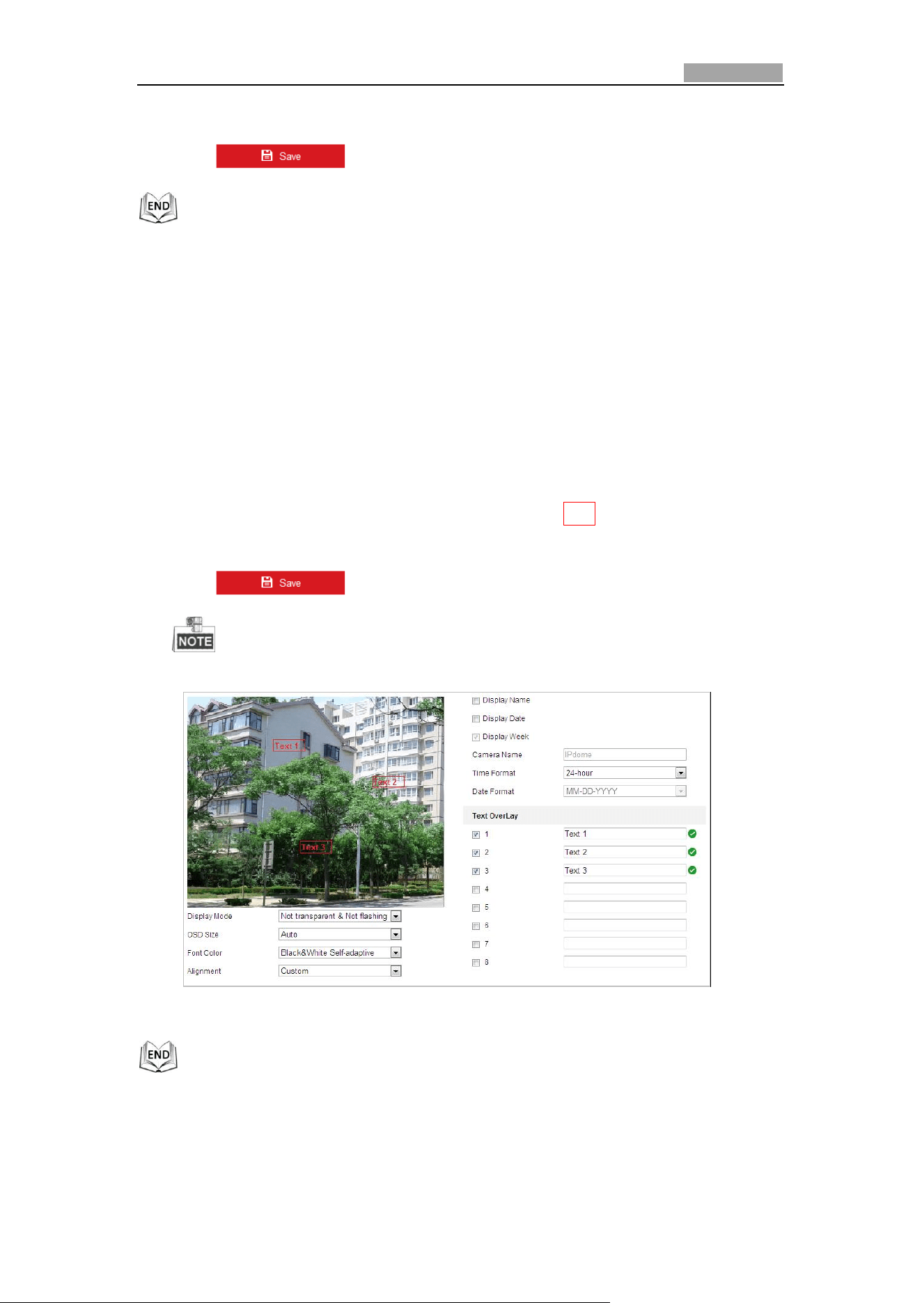
Network Speed Dome User Manual
112
and select the font color on your demand.
7. Click to activate above settings.
6.3.3 Configuring Text Overlay Settings
Purpose:
You can customize the text overlay.
Steps:
1. Enter the Text Overlay Settings interface:
Configuration > Image > OSD Settings
2. Check the checkbox in front of textbox to enable the on-screen display.
3. Input the characters in the textbox.
4. Use the mouse to click and drag the red text frame Text in the live view window
to adjust the text overlay position.
5. Click .
There are up to 8 text overlays configurable.
Figure 6-37 Text Overlay Settings
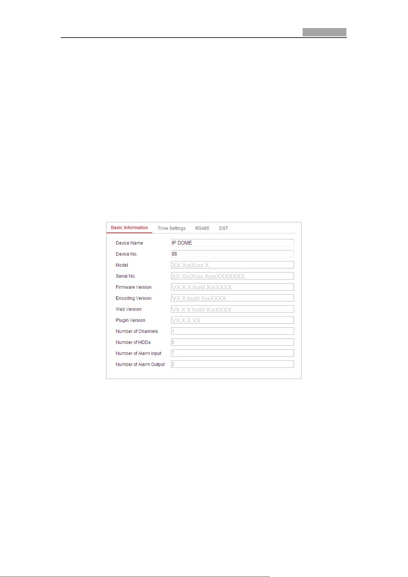
Network Speed Dome User Manual
113
6.4 Configuring System Settings
6.4.1 System Setting
Viewing Basic Information
Enter the Basic Information interface:
Configuration > System > System Settings > Basic Information
In the Basic Information interface, you can edit the Device Name.
Other information of the network speed dome, such as Model, Device No., Serial No.,
Firmware Version, Encoding Version, Number of Channels, Number of HDDs, Number
of Alarm Input and Number of Alarm Output are displayed. The information cannot
be changed in this menu. It is the reference for maintenance or modification in
future.
Figure 6-38 Device Information
Time Settings
Purpose:
You can follow the instructions in this section to configure the time which can be
displayed on the video. There are Time Zone, Time Synchronization, Daylight Saving
Time (DST) functions for setting the time. Time Synchronization consists of auto
mode by Network Time Protocol (NTP) server and manual mode.
To enter the Time Settings interface:
Configuration > System > System Settings > Time Settings
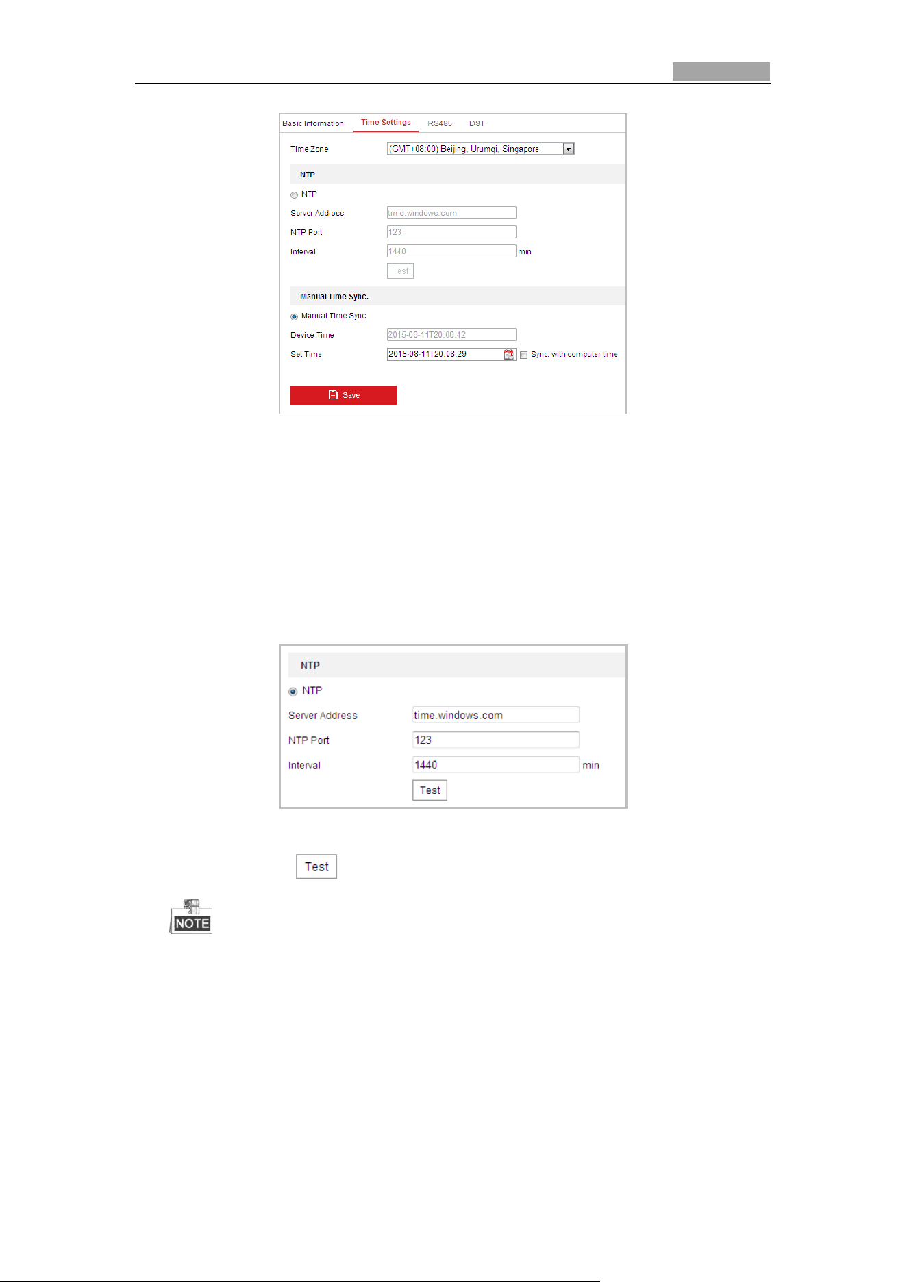
Network Speed Dome User Manual
114
Figure 6-39 Time Settings
Configuring Time Synchronization by NTP Server
Steps:
(1) Check the radio button to enable the NTP function.
(2) Configure the following settings:
Server Address: IP address of NTP server.
NTP Port: Port of NTP server.
Interval: The time interval between the two synchronizing actions by NTP server.
It can be set from 1 to 10080 minutes.
Figure 6-40 Time Sync by NTP Server
(3) You can click the button to check whether the confguration is succeeded.
If the speed dome is connected to a public network, you should use a NTP
server that has a time synchronization function, such as the server at the
National Time Center (IP Address: 210.72.145.44). If the speed dome is set
in a customized network, NTP software can be used to establish a NTP server
for time synchronization.
Configuring Time Synchronization Manually
Steps:
(1) Check the Manual Time Sync radio button.
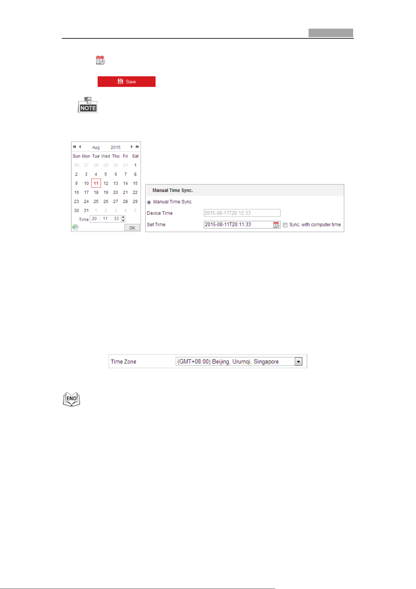
Network Speed Dome User Manual
115
(2) Click to set the system time from the pop-up calendar.
(3) Click to save the settings.
You can also check the Sync. with computer time checkbox to synchronize
the time of the speed dome with the time of your computer.
Figure 6-41 Time Sync Manually
Select the Time Zone
Purpose:
When the speed dome is taken to another time zone, you can use the Time Zone
function to adjust the time. The time will be adjusted according to the original
time and the time difference between the two time zones.
From the Time Zone drop-down menu as shown in Figure 6-42, select the Time
Zone in which the speed dome locates.
Figure 6-42 Time Zone Settings
Configuring RS-485
Purpose:
The RS-485 serial port is used to control the PTZ of the camera. The configuring of
the PTZ parameters should be done before you control the PTZ unit.
Steps:
1. Enter RS-485 Port Setting interface:
Configuration > System > System Settings > RS485
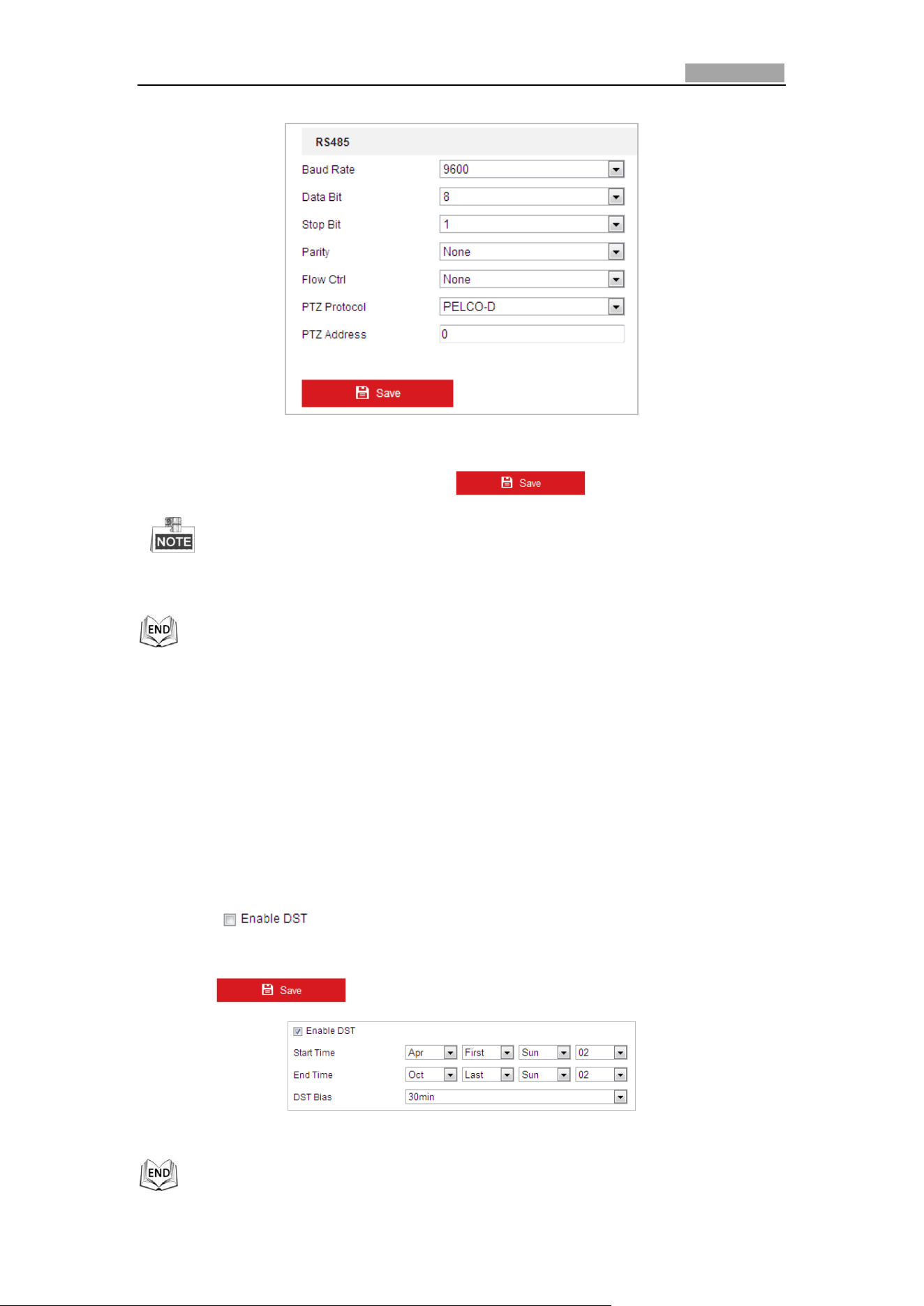
Network Speed Dome User Manual
116
Figure 6-43 RS-485 Settings
2. Set the RS-485 parameters and click to save the settings.
The Baudrate, PTZ Protocol and PTZ Address parameters of the speed dome
should be exactly the same as those of the control device.
Configuring DST (Daylight Saving Time)
Purpose:
If there is the habit of adjusting clocks forward in your country in certain time period
of a year, you can turn this function on. The time will be adjusted automatically when
the Daylight Saving Time (DST) comes.
Steps:
1. Enter the DST interface by Configuration > System > System Settings > DST
2. Check to enable the DST function.
3. Set the date of the DST period.
4. Click to save the settings.
Figure 6-44 DST Settings
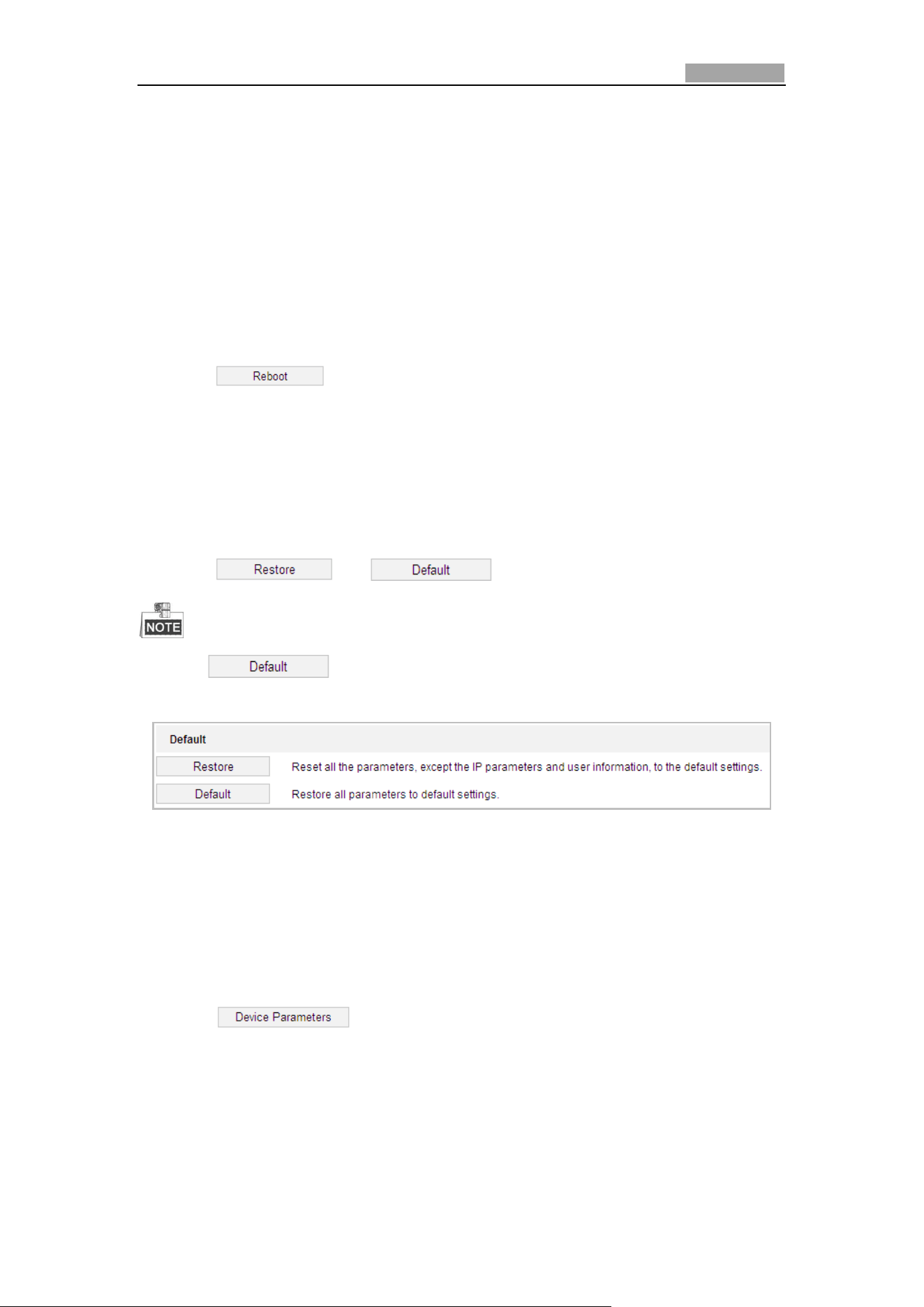
Network Speed Dome User Manual
117
6.4.2 Maintenance
Upgrade & Maintenance
Rebooting the Speed Dome
Steps:
1. Enter the Maintenance interface:
Configuration > System > Maintenance > Upgrade & Maintenance:
2. Click to remotely reboot the network speed dome.
Restoring Default Settings
Steps:
1. Enter the Maintenance interface:
Configuration > System > Maintenance > Upgrade & Maintenance:
2. Click or to restore the default settings.
Clicking button will restore all the parameters to default settings
including the IP address and user information. Please use this button with caution.
Figure 6-45 Restore Default Settings
Exporting Configuration File
Steps:
1. Enter the Maintenance interface:
Configuration > System > Maintenance > Upgrade & Maintenance:
2. Click to select the directory as the saving path to start
exporting configuration file.
Importing Configuration File
Steps:
1. Enter the Maintenance interface:
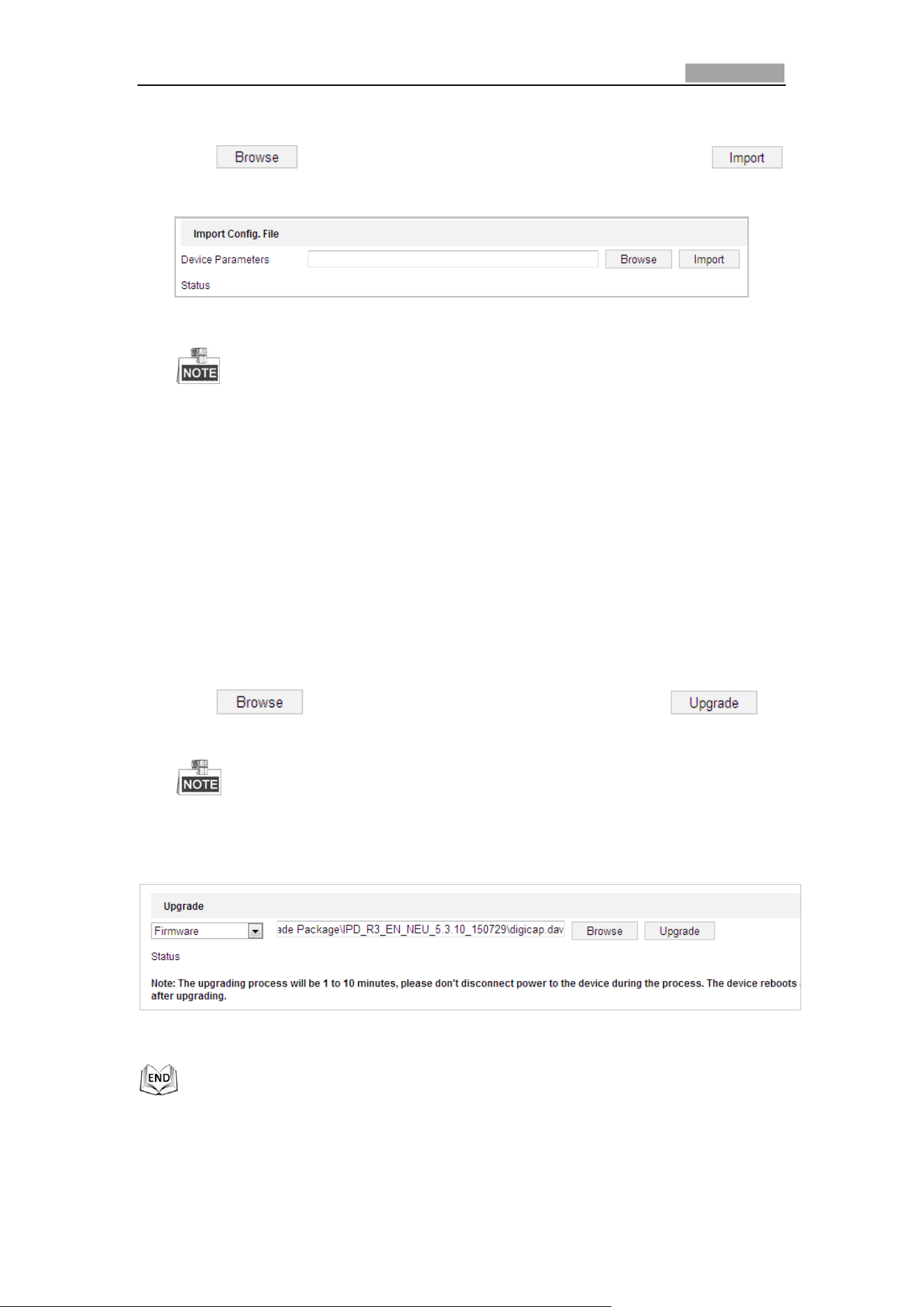
Network Speed Dome User Manual
118
Configuration > System > Maintenance > Upgrade & Maintenance:
2. Click to select the local configuration file and then click
to start importing configuration file.
Figure 6-46 Import Configuration File
You need to reboot the speed dome after importing configuration file.
Upgrading the System
Steps:
1. Enter the Upgrade & Maintenance interface:
Configuration >System > Maintenance > Upgrade & Maintenance
2. Select Firmware or Firmware Directory.
Firmware: when you select Firmware, you need to find the firmware in your
computer to upgrade the device.
Firmware Directory: You need to find the directory where the firmware
locates. The device can find the firmware in the directory automatically.
3. Click to select the local upgrade file and then click to
start remote upgrade.
The upgrading process will take 1 to 10 minutes. Please do not disconnect
the power of the speed dome during the upgrading process. The speed
dome reboots automatically after upgrading.
Figure 6-47 Remote Upgrade
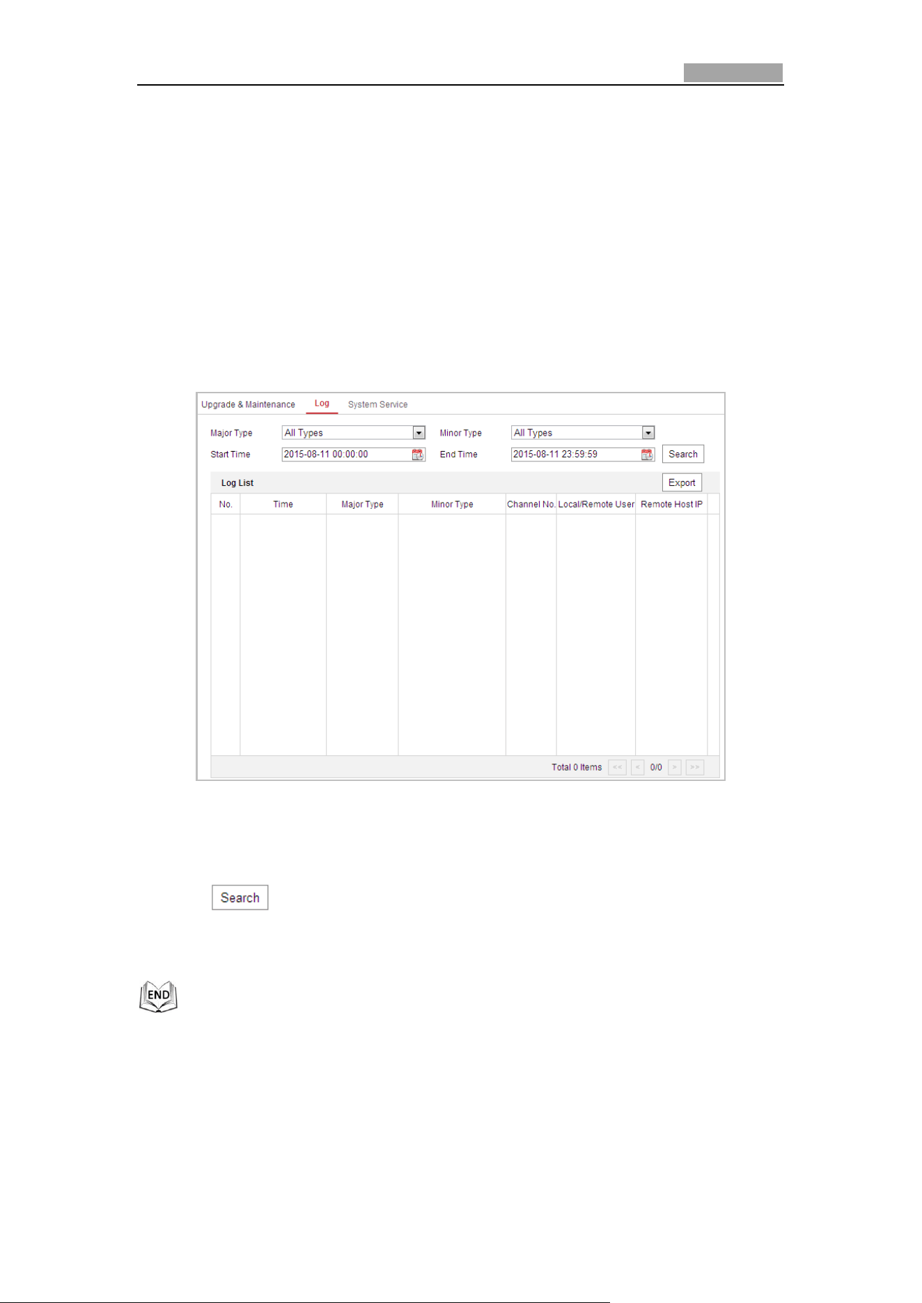
Network Speed Dome User Manual
119
Log Searching
Purpose:
The operation, alarm, exception and information of the speed dome can be stored in
log files. You can also export the log files on your demand.
Before you start:
Please configure network storage for the speed dome or insert a SD card in the speed
dome.
Steps:
1. Enter the Log interface:
Configuration >System > Maintenance > Log
Figure 6-48 Log Searching Interface
2. Set the log search conditions to specify the search, including the Major Type,
Minor Type, Start Time and End Time as shown in Figure 6-48.
3. Click to search log files. The matched log files will be displayed on the
Log List.
4. To export the log files, click Save Log to save the log files in your computer.
System Service
Steps:
1. Enter the interface of configuring the remote connection:
Configuration > System > Maintenance > System Service
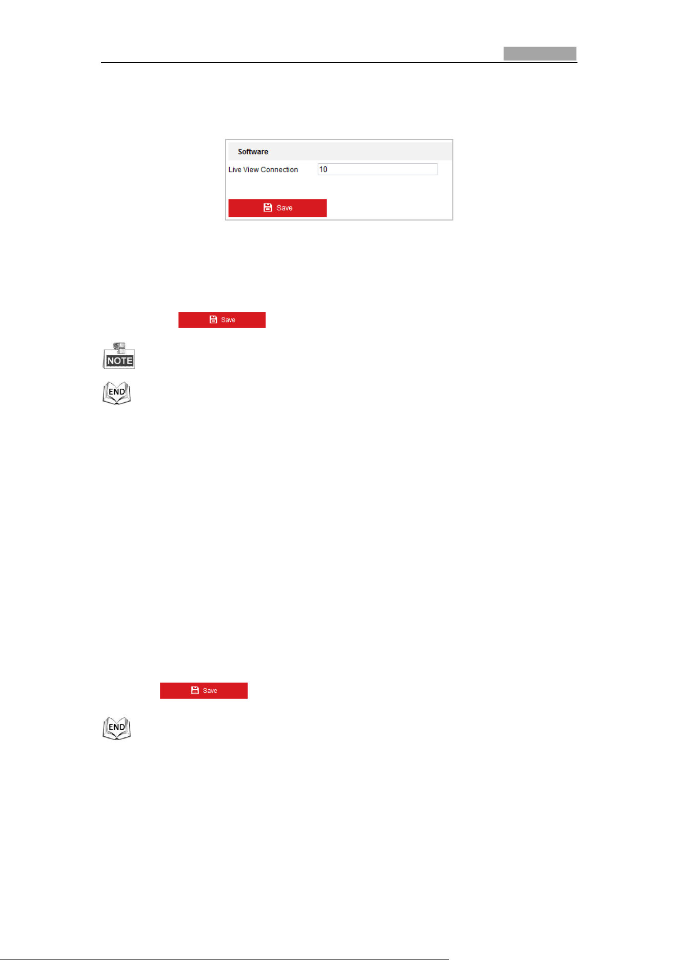
Network Speed Dome User Manual
120
2. Input a number in text field as the upper limit of the remote connection number.
E.g. when you specify the remote connection number as 10, then the 11th
remote connection cannot be established.
Figure 6-49 Live View Connection Settings
3. Check the checkbox to enable the supplement light function, and then the light
will be turned on automatically when the illumination is not enough for the video
monitoring. (Optional)
4. Click the button to activate the settings.
The supplement light configuration is only supported by certain models.
6.4.3 Security
Configuring Authentication
Purpose:
You can specifically secure the stream data of live view.
Steps:
1. Enter the Authentication interface:
Configuration> System> Security > Authentication
2. Set the authentication mode for RTSP authentication.
RTSP Authentication: Select the authentication mode as basic or disable in the
dropdown list to enable or disable the RTSP authentication.
3. Click to save the settings.
Configuring Anonymous Visit
Enabling this function allows visit for whom doesn’t have the user name and
password of the device.
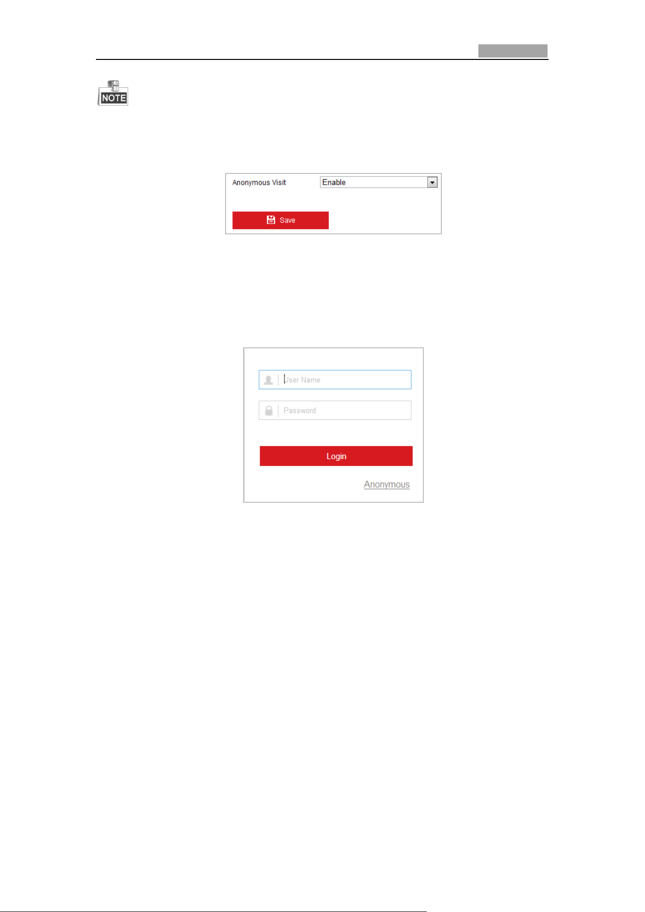
Network Speed Dome User Manual
121
Only live view is available for the anonymous user.
Steps:
1. Enter the Anonymous Visit interface:
Configuration> System> Security > Anonymous Visit
Figure 6-50 Anonymous Visit
2. Set the Anonymous Visit permission Enable or Disable in the drop-down list to
enable or disable the anonymous visit.
3. Click Save to save the settings.
There will be a checkbox of Anonymous by the next time you logging in.
Figure 6-51 Login Interface with an Anonymous Checkbox
4. Click Anonymous to login automatically.
By permitting the Anonymous “Live View” function, you may enable others to access
your speed dome and view live images without providing login credentials. It
therefore is critical when permitting the Anonymous "Live View" function to ensure
that your camera's field of view does not impact the privacy of individuals whose
images might be captured without authorization.
Given its inherent intrusiveness, video surveillance is inappropriate in areas where
people have a higher expectation of privacy.
Configuring IP Address Filter
Purpose:
With this function on, the camera allows certain IP addresses whether to log in or
not.
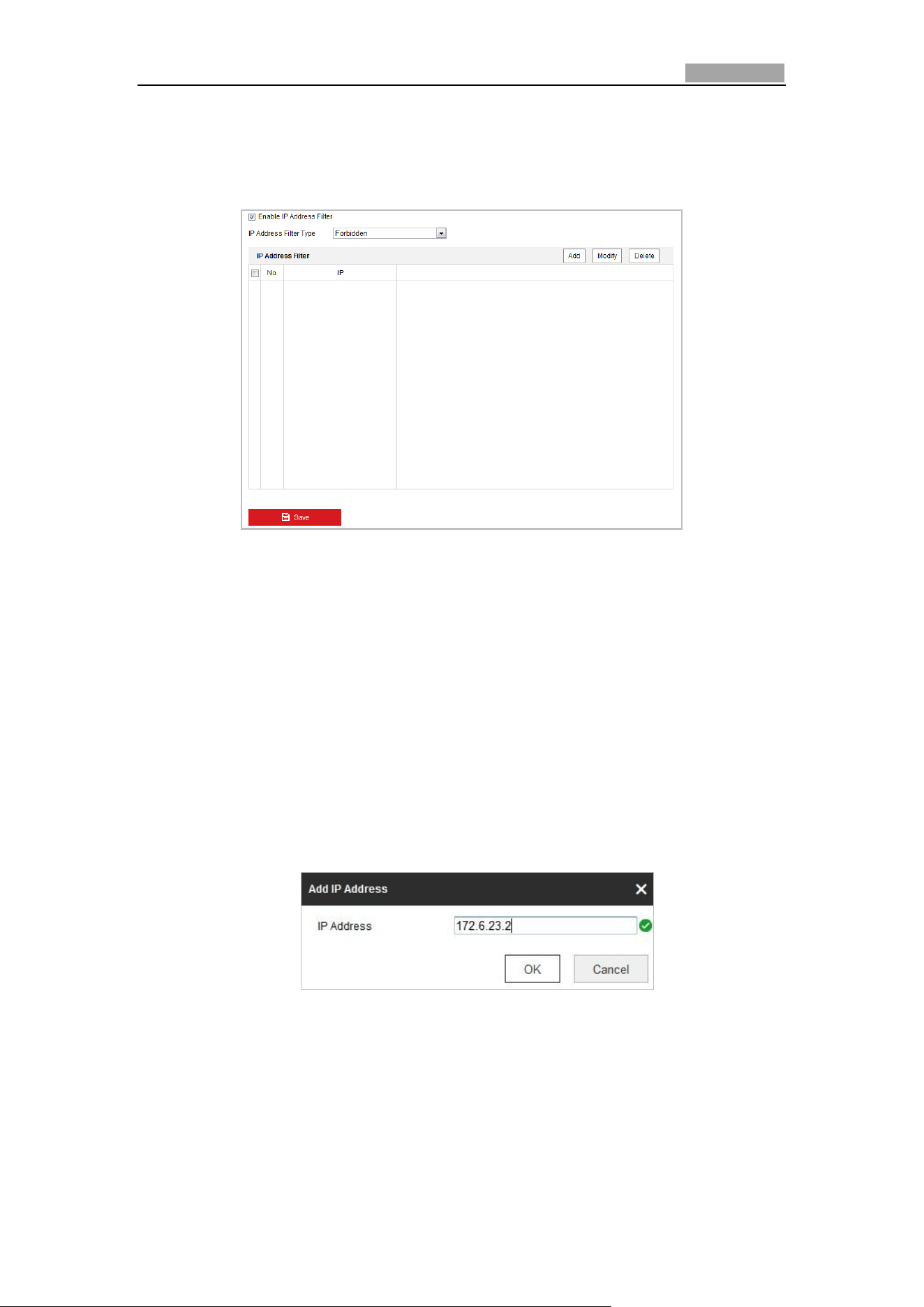
Network Speed Dome User Manual
122
Steps:
1. Enter IP Address Filter interface:
Configuration > System > Security > IP Address Filter
Figure 6-52 IP Address Filter
2. Check the checkbox of Enable IP Address Filter.
3. Select the type of IP Address Filter in the drop-down list, Forbidden and Allowed
are selectable.
4. Set the IP Address Filter list.
Add an IP Address
Steps:
(1) Click the Add to add an IP.
(2) Input the IP Adreess.
Figure 6-53 Add an IP
(3) Click the OK to finish adding.
Modify an IP Address
Steps:
(1) Left-click an IP address from filter list and click Modify.
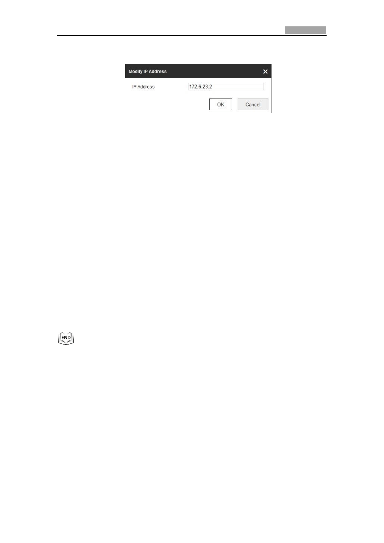
Network Speed Dome User Manual
123
(2) Modify the IP address in the text filed.
Figure 6-54 Modify an IP
(3) Click the OK to finish modifying.
Delete an IP Address
Left-click an IP address from filter list and click Delete.
Delete all IP Addresses
Click Clear to delete all the IP addresses.
5. Click Save to save the settings.
Configuring Security Service Settings
Steps:
1. Enter the Security Service interface:
Configuration> System > Security > Security Service
2. Check the checkbox to enable the SSH function.
Enable SSH: Enabling SSH (Secure Shell) function is to encrypt and compress the
data and to reduce the transmission time.
6.4.4 User Management
Enter the User Management interface:
Configuration > System > User Management
The admin user has access to create, edit or delete other accounts. Up to 31 user
accounts can be created.
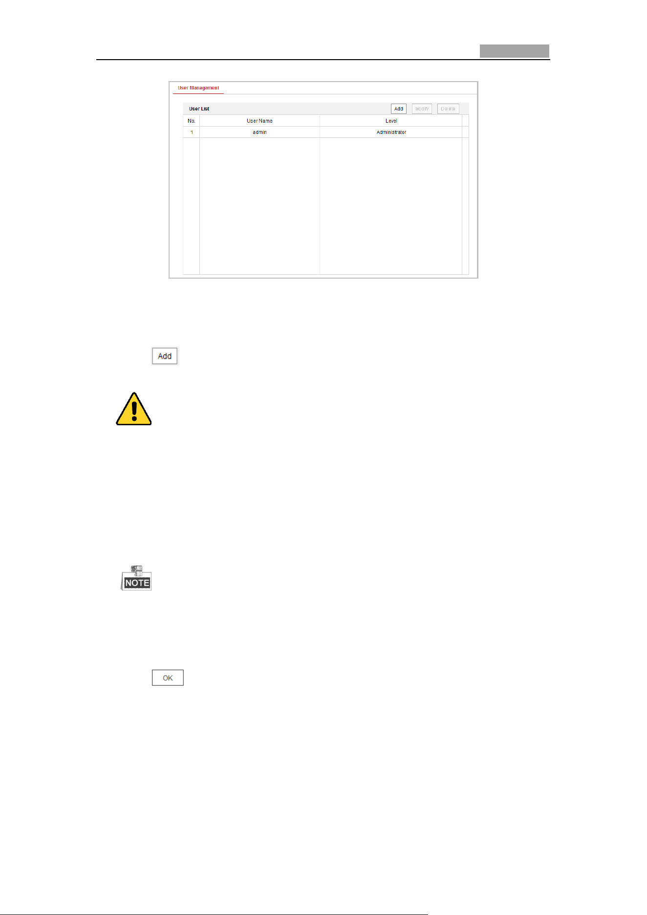
Network Speed Dome User Manual
124
Figure 6-55 User Information
Add a User
Steps:
1. Click to add a user.
2. Input the new User Name, select Level and input Password.
For your privacy and to better protect your system against security risks, we
strongly recommend the use of strong passwords for all functions and network
devices. The password should be something of your own choosing (Using a
minimum of 8 characters, including at least three of the following categories:
upper case letters, lower case letters, numbers, and special characters.) in
order to increase the security of your product.
Proper configuration of all passwords and other security settings is the
responsibility of the installer and/or end-user.
The level indicates the permissions you give to the user. You can define the
user as Operator or User.
3. In the Basic Permission field and Camera Configuration field, you can check or
uncheck the permissions for the new user.
4. Click to finish the user addition.
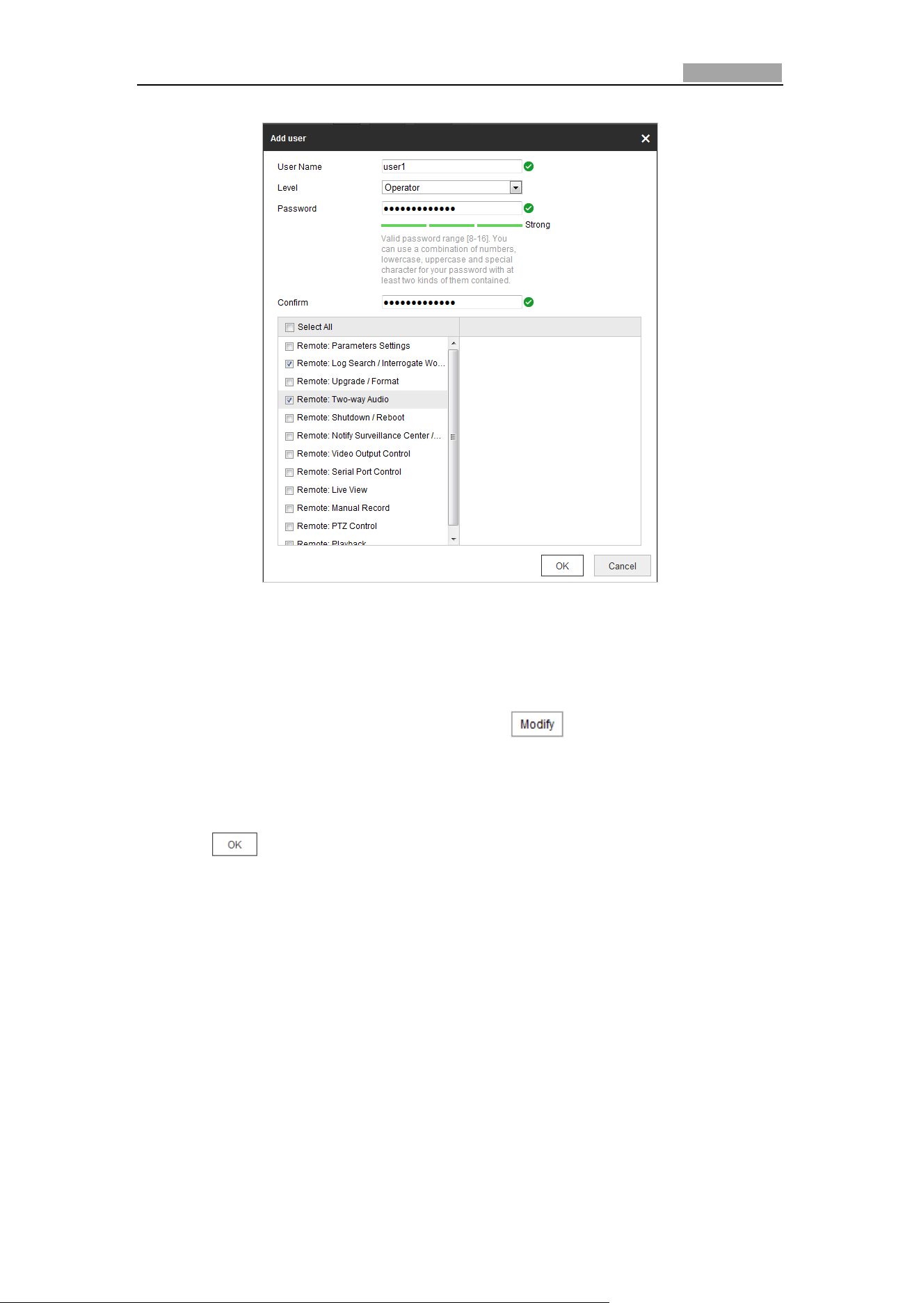
Network Speed Dome User Manual
125
Figure 6-56 Add a User
Modify a User
Steps:
1. Click to select the user from the list and click .
2. Modify the User Name, Level or Password.
3. In the Basic Permission field and Camera Configuration field, you can check or
uncheck the permissions.
4. Click to finish the user modification.
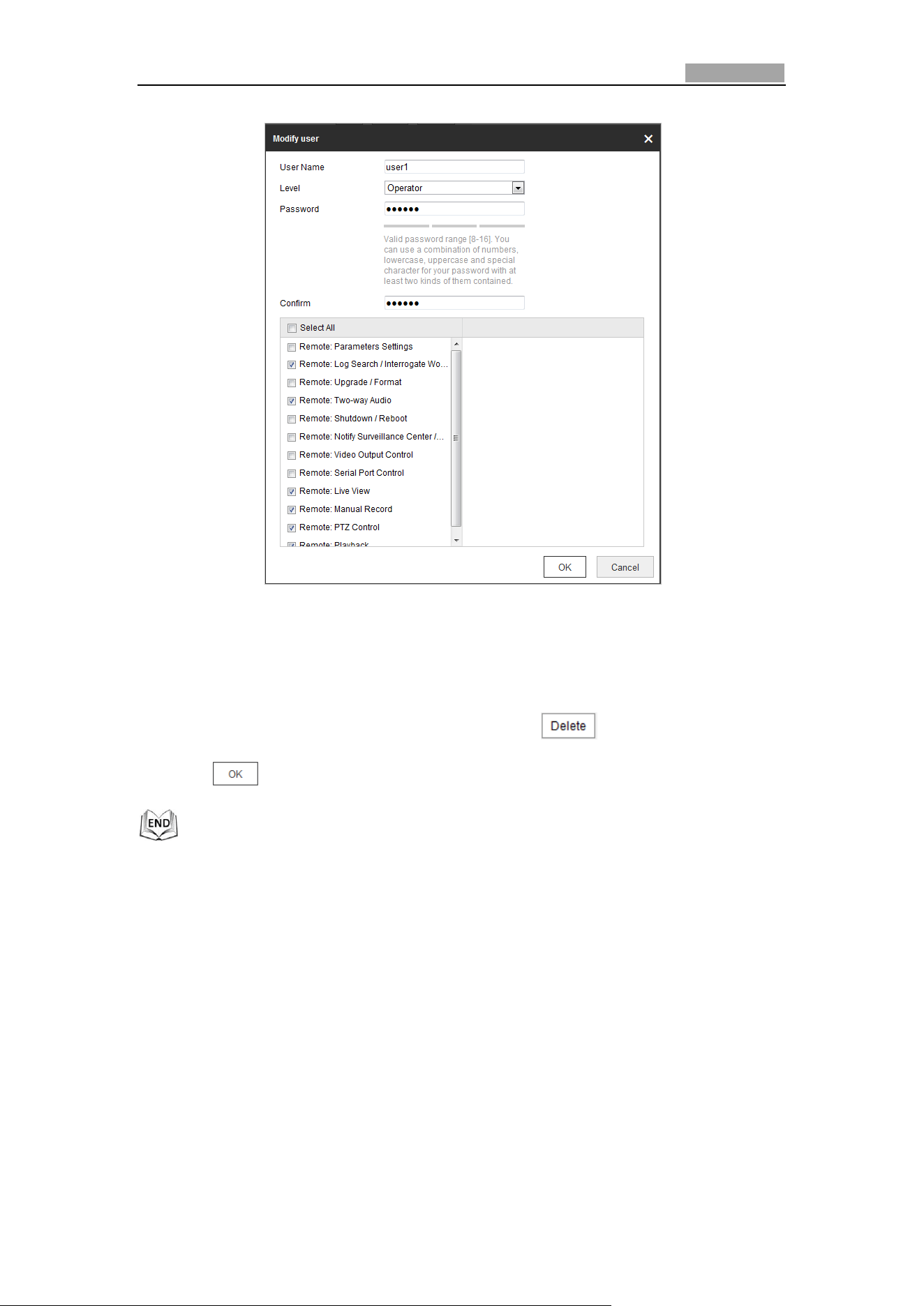
Network Speed Dome User Manual
126
Figure 6-57 Modify a User
Delete a User
Steps:
1. Click the user name you want to delete and click .
2. Click on the pop-up confirmation box to delete the user.
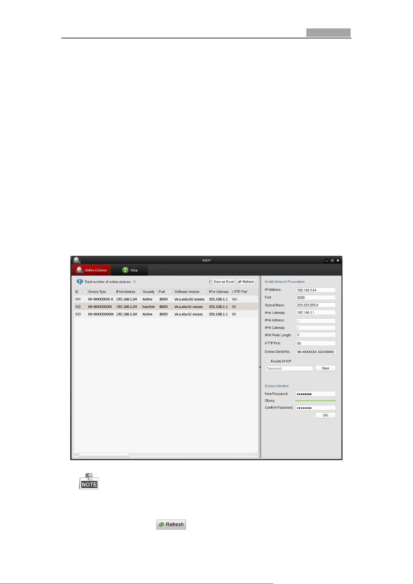
User Manual of Network Speed Dome
127
Appendix
Appendix 1 SADP Software Introduction
Description of SADP
SADP (Search Active Devices Protocol) is a kind of user-friendly and installation-free
online device search tool. It searches the active online devices within your subnet
and displays the information of the devices. You can also modify the basic network
information of the devices using this software.
Search active devices online
Search online devices automatically
After launch the SADP software, it automatically searches the online devices
every 15 seconds from the subnet where your computer locates. It displays
the total number and information of the searched devices in the Online
Devices interface. Device information including the device type, IP address
and port number, etc. will be displayed.
Figure A.1.1 Searching Online Devices
Device can be searched and displayed in the list in 15 seconds after it
went online; it will be removed from the list in 45 seconds after it went offline.
Search online devices manually
You can also click to refresh the online device list manually. The

Network Speed Dome User Manual
128
newly searched devices will be added to the list.
You can click or on each column heading to order the information;
you can click to expand the device table and hide the network parameter panel on
the right side, or click to show the network parameter panel.
Modify network parameters
Steps:
1. Select the device to be modified in the device list and the network parameters of
the device will be displayed in the Modify Network Parameters panel on the
right side.
2. Edit the modifiable network parameters, e.g. IP address and port number.
3. Enter the password of the admin account of the device in the Password field and
click to save the changes.
For your privacy and to better protect your system against security risks, we
strongly recommend the use of strong passwords for all functions and network
devices. The password should be something of your own choosing (Using a
minimum of 8 characters, including at least three of the following categories:
upper case letters, lower case letters, numbers, and special characters.) in
order to increase the security of your product.
Proper configuration of all passwords and other security settings is the
responsibility of the installer and/or end-user.
Figure A.1.2 Modify Network Parameters
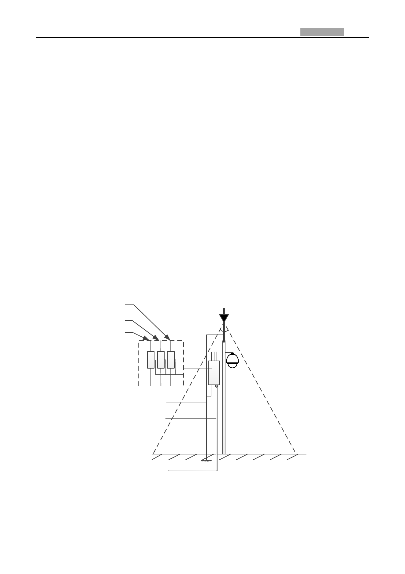
Network Speed Dome User Manual
129
Appendix 2 Statics, Interference Lightning and Surge Protection
This product adopts TVS plate lightning protection technology to avoid damage caused by pulse
signal that is below 3000V, like instantaneous lighting stroke, surging, etc. According to the actual
outdoor situation, necessary protection measures must be taken, besides ensuring the electrical
safety.
The distance between signal transmission wires and High-voltage equipment or high-voltage
cable is at least 50m.
Outdoor wiring should better be routed under eaves as much as possible.
In the open field, wiring should be buried underground in sealed steel pipe, and the steel-pipe
should be one-point grounding. Overhead routing method is forbidden.
In strong thunderstorm area or high induction voltage areas (such as high-voltage transformer
substation), high power lightning protection apparatus and lightning conductor are necessary to
be added.
The design of lightning protection and grounding of the outdoor devices and cables should be
considered together with the lightning protection demand of buildings. It also must conform to
the related national standards and industrial standards.
The system should be equipotential grounded. The grounding equipment must conform to the
demands of system anti-jamming and electrical safety both and it must not appear short circuit
or mixed circuit with the zero conductor of strong grid. When the system is grounded alone, the
resistance should be no more than 4Ω. The sectional area of the grounding cable should be no
less than 25mm2. For grounding instructions, please refer to the Installation Manual of Speed
Dome.
Lightening Rod
45°
The speed dome must be
installed in the 45° protection
area of the lightening rod.
The impedance of the grounding
wire can be no more than 4Ω.
Steel Protection Tube
Video Arrester
Communication
Arrester
Power Arrester
Figure A.3.1 Lightning & Surge Protection
Grounding for Cement Pole/Wall Installation:
When the speed dome is installed in environment where is relatively insulating to the earth, e.g.,
cement pole or cement wall, then only the control center requires proper grounded locally. Refer to
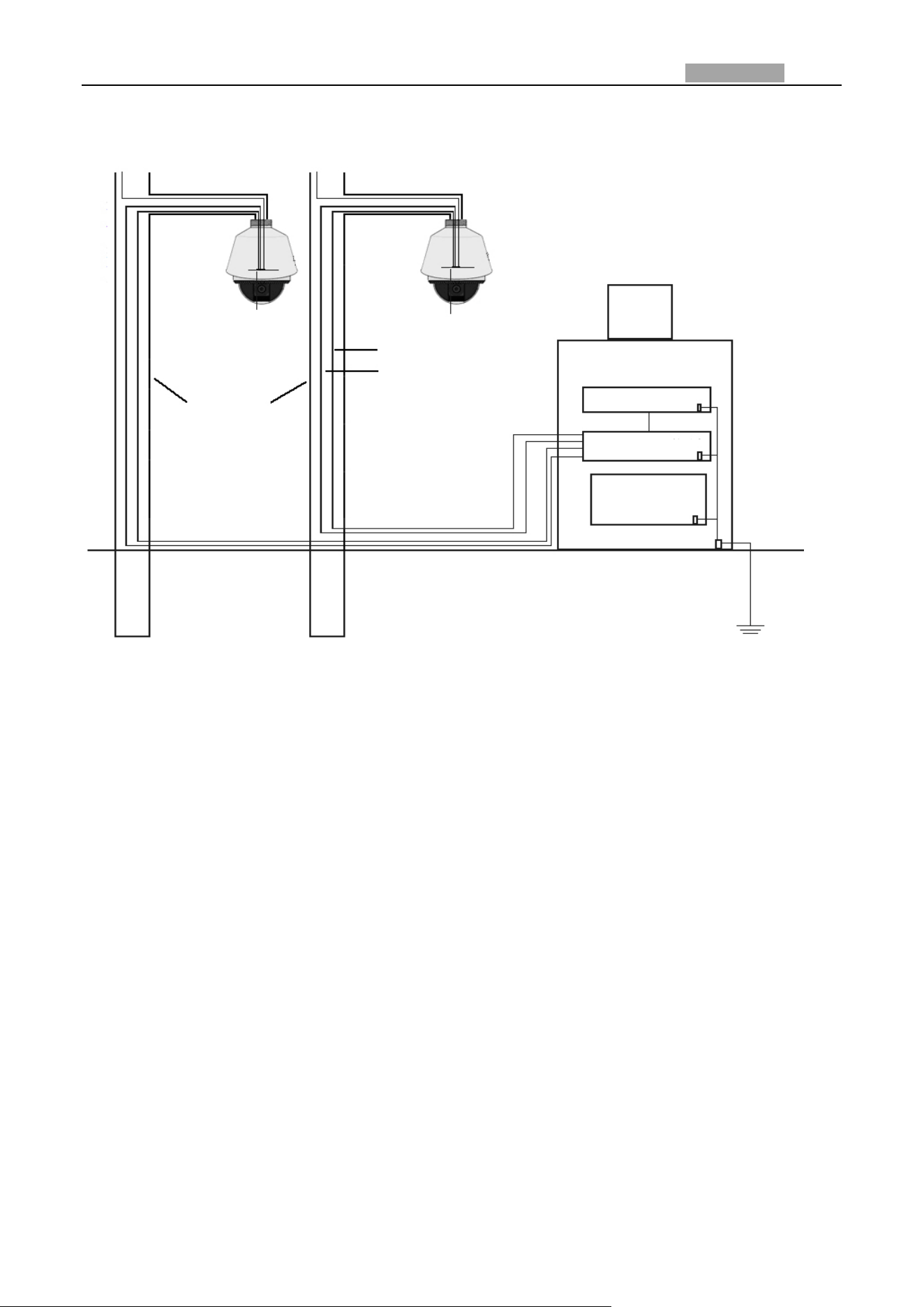
Network Speed Dome User Manual
130
the following figure.
PowerPower
Power supply board
Power supply board
Video cable
Control line
Cement pole/wall
Display
Operating center
Keyboard
DVR
UPS
GND
GND
GND
GND
1.5m underground
Figure A.3.2 Grounding in Cement Pole/Wall Installation
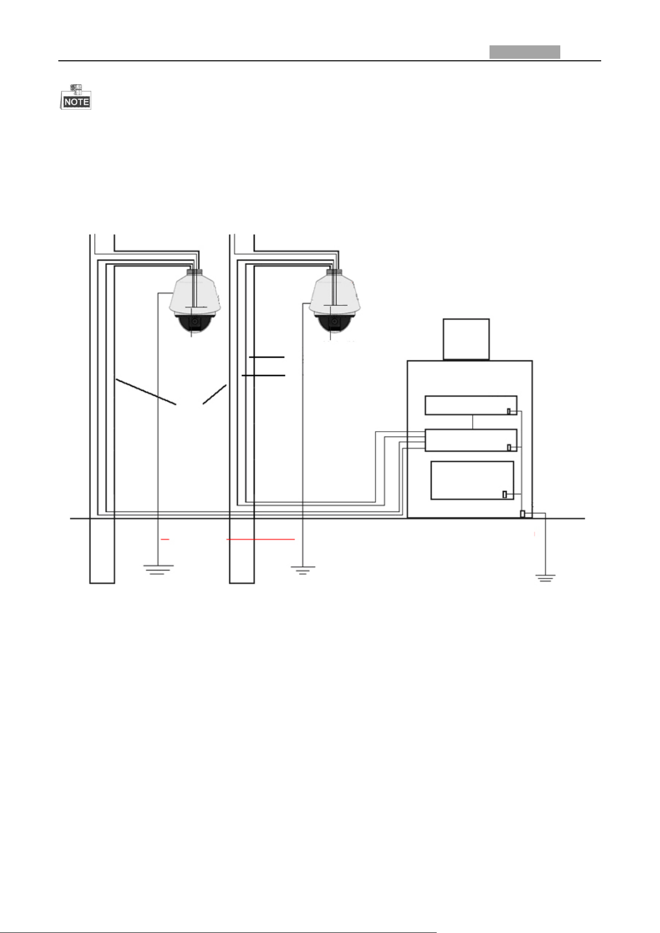
Network Speed Dome User Manual
131
Because the signal transmission media of fiber optical speed dome and network speed dome
are isolated from the control center, they must be grounded locally to protect dome against
damages.
If the dome is installed in strong thunderstorm area, it must be grounded locally to release
lightening or suchlike high energy to protect dome against damages. Refer to the following
figure.
Power
Power
Power supply board Power supply board
Video cable
Control line
Cement pole/wall
Display
Operating Center
Keyboard
DVR
UPS
GND
GND
GND
GND
1.5m underground
1.5m
underground
Figure A.3.3 Lightening-protection Grounding in Cement Pole/Wall Installation
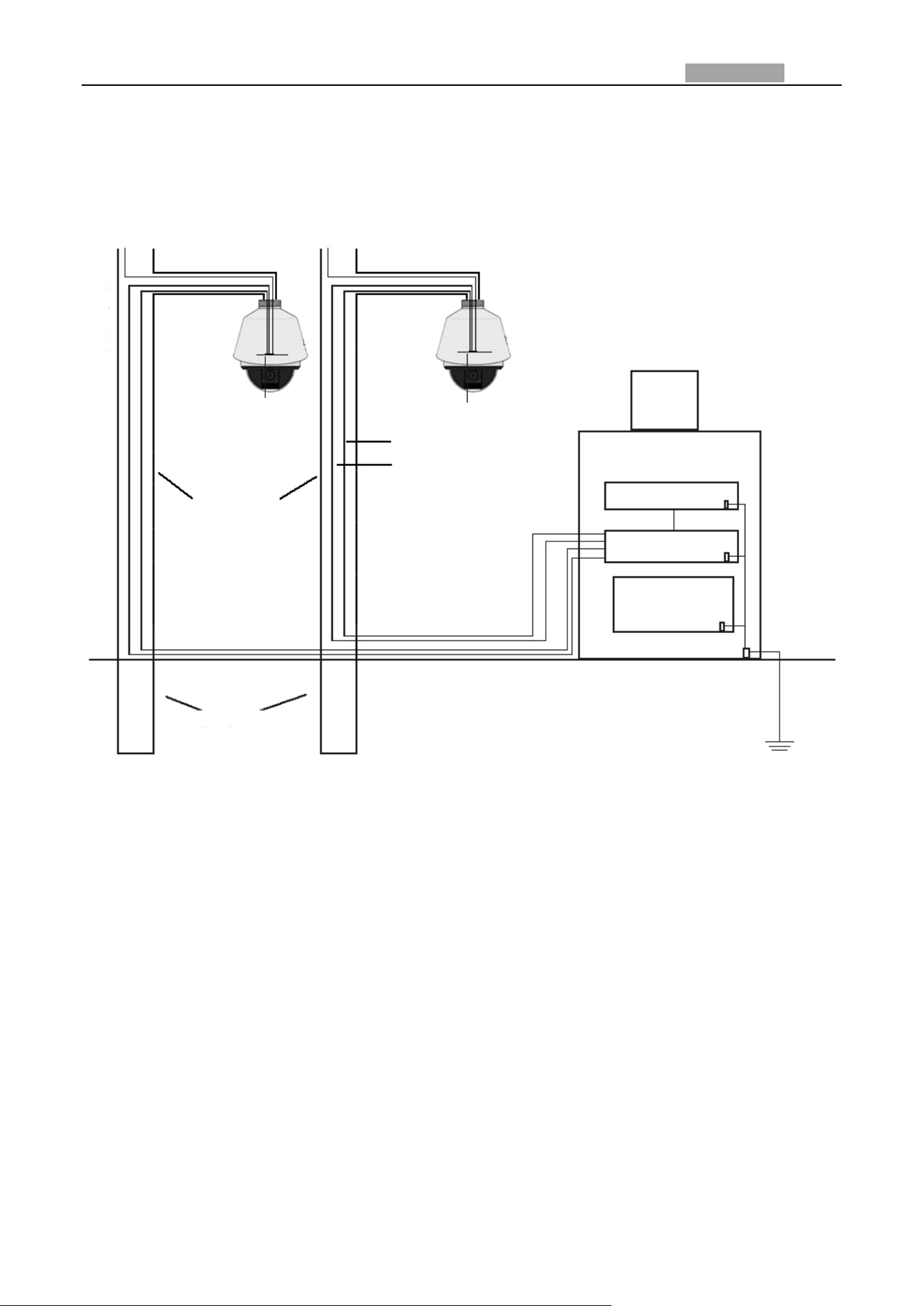
Network Speed Dome User Manual
132
Grounding for Metal Pole Installation:
When the speed dome is installed in environment where is conductive to the earth, e.g., metal pole,
then the grounding of dome can be achieved by the properly grounded metal pole, meanwhile, the
control center must be grounded locally as well. Refer to the following figure.
Power
Power
Power supply board
Power supply board
Video cable
Control line
Metal pole/surface
Display
Operating Center
Keyboard
DVR
UPS
GND
GND
GND
GND
1.5m underground
1.5m
underground
Figure A.3.4 Grounding in Metal Pole Installation
Note: If the fiber optics, lightening protector or other device are applied during the transmission of
speed dome, such devices as well as the video cables routing through must be proper grounded.
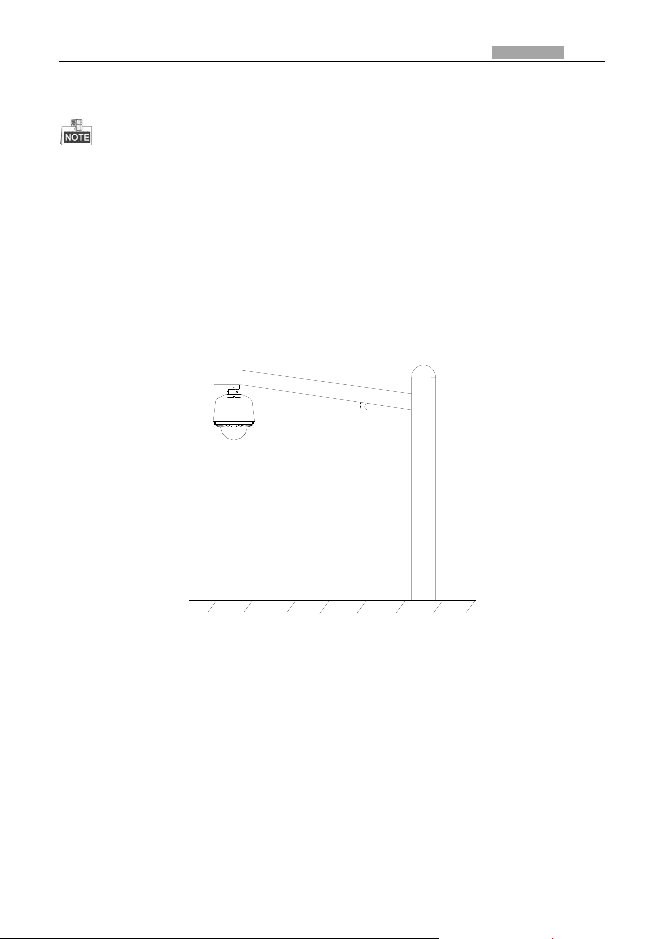
Network Speed Dome User Manual
133
Appendix 3 Waterproof
The long-arm wall mount is recommended for the outdoor application of speed dome.
You cannot use the short-arm wall mount or pendant mount for outdoor application, because it
is not water-proof.
It is recommended to use the mount with inner threaded interface and good waterproof
performance.
If you use a mount with outer threaded interface, please adopt waterproof measures to the
adapter applied between the mount and the dome.
Do not install indoor speed dome to the outdoor environment.
L-shape Pole Mount
Make sure that the L-shape pole mount is designed with a certain inclination angle as shown in
following figure. Water won’t flow from the pole into the speed dome with the inclination angle.
θ
Figure A.4.1 Customized Mount

Network Speed Dome User Manual
134
Appendix 4 Bubble Maintenance
The bubble is a transparent plastic. The dust, oil and finger print, etc. will cause scratch or image
blur. Please refer to the following method to clean the bubble.
Handling dust
Use oil free soft brush or blowing dust ball to clean the dust.
Handling oil
Steps:
1. Wipe off the water-drop or oil by soft cloth and dry the bubble.
2. Use oil free cotton cloth to wipe the bubble with alcohol or detergent.
3. Change the cloth to wipe the bubble until the bubble is clean.
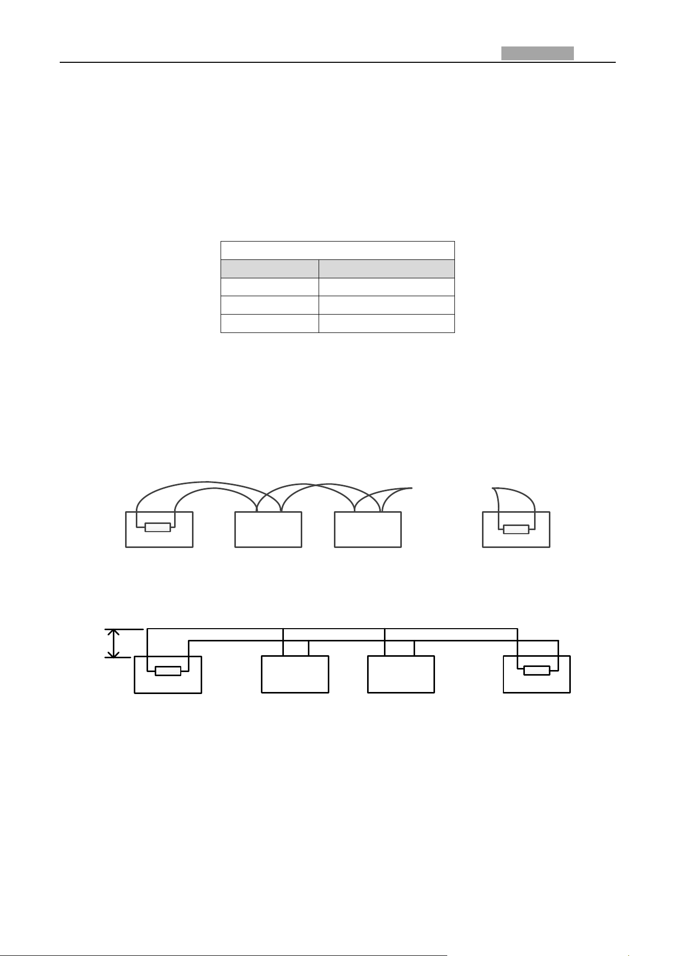
Network Speed Dome User Manual
135
Appendix 5 RS485 Bus Connection
General Property of RS485 Bus
According to RS485 industry bus standard, RS485 is a half-duplex communication bus which has
120Ω characteristic impendence, the maximum load ability is 32 payloads (including controller
device and controlled device).
RS485 Bus Transmission Distance
When using 0.56mm (24AWG) twisted-pair line, according to different baudrate, the maximum
transmission distance theory table is shown as below:
Max. Distance of RS485 Transmission
Baudrate
Max Distance
2400BPS
1800m
4800BPS
1200m
9600BPS
800m
The transmission distance will be decreased if we use the thinner cable, or use this product under
the strong electromagnetic interference situation, or there are lots of devices are added to the bus;
on the contrary, the transmission distance will be increased.
Connection Methods
RS485 industry bus standard require daisy-chain connection method between any devices, both
sides have to connect a 120Ω terminal resistance (show as Diagram 1), the simplified connection
method is shown as diagram 2, but the distance of “D” should not be too long.
1#
2#
3#
32#
…
120Ω
120Ω
Figure A.6.1 RS485 Connection 1
…
Controller
A+
B-
1#
2# 31#
A+ B-
D
Figure A.6.2 RS485 Connection 2
Problems in the Practical Application
Normally, users adopt star-shape connection method in construction, under this situation, the
terminal resistors must be connected between two farthest devices (as Figure A-9, 1# and 15#), but
this connection method is not satisfy the requirement of the RS485 industry standard so that it will
lead to some problems such as signal reflection, anti-jamming ability decline when the devices are
faraway. At this time, the dome will be uncontrollable, or self-running, etc.
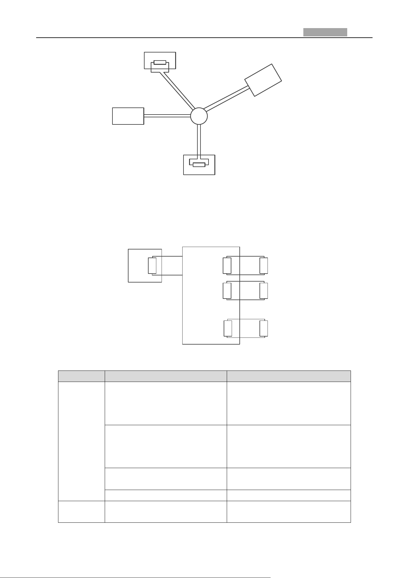
Network Speed Dome User Manual
136
1#
6#
15#
32#
Controller
Figure A.6.3 Star Shape Connection
For such case, the best way is adding a RS485 distributor. This product can effectively change the
star-shape connection to which satisfies the requirement of RS485 industry standard, in order to
avoid those problems and improve the communication reliability. Refer to the following figure.
A+
B-
RS485 Distributor
120Ω
1#
2#
16#
120Ω
120Ω
Figure A.6.4 RS485 Distributor
Troubleshooting of RS485 communication
Problem
Possible Reasons
To Solve the Problem
The speed
dome does
the
self-test
action but
cannot be
controlled
remotely.
1. The address or baudrate of the
speed dome does not match with
those of remote control device.
1. Adjust the address and
baudrate of the remote control
device to match with those of the
speed dome.
2. The wire RS485+ connects to
the interface RS485- and wire
RS485- connects to the interface
RS485+.
2. Connect the wire RS485+ to the
interface RS485+ and wire RS485-
to the interface RS485-.
3. The RS485 wire is
disconnected.
3. Reconnect the RS485 wire
tightly.
4. RS485 wire is broken.
4. Change a RS485 wire.
The speed
dome can
1. The connection is loose.
1. Reconnect the RS485 wire
tightly.

Network Speed Dome User Manual
137
Problem
Possible Reasons
To Solve the Problem
be
controlled
but not
smoothly.
2. RS485+ or RS485-wire is
broken.
2. Change a RS485 wire.
3. The speed dome is too far away
from the remote control device.
3. Add a terminal resistor.
4. Too many speed domes are
connected.
4. Add a RS485 distributor.
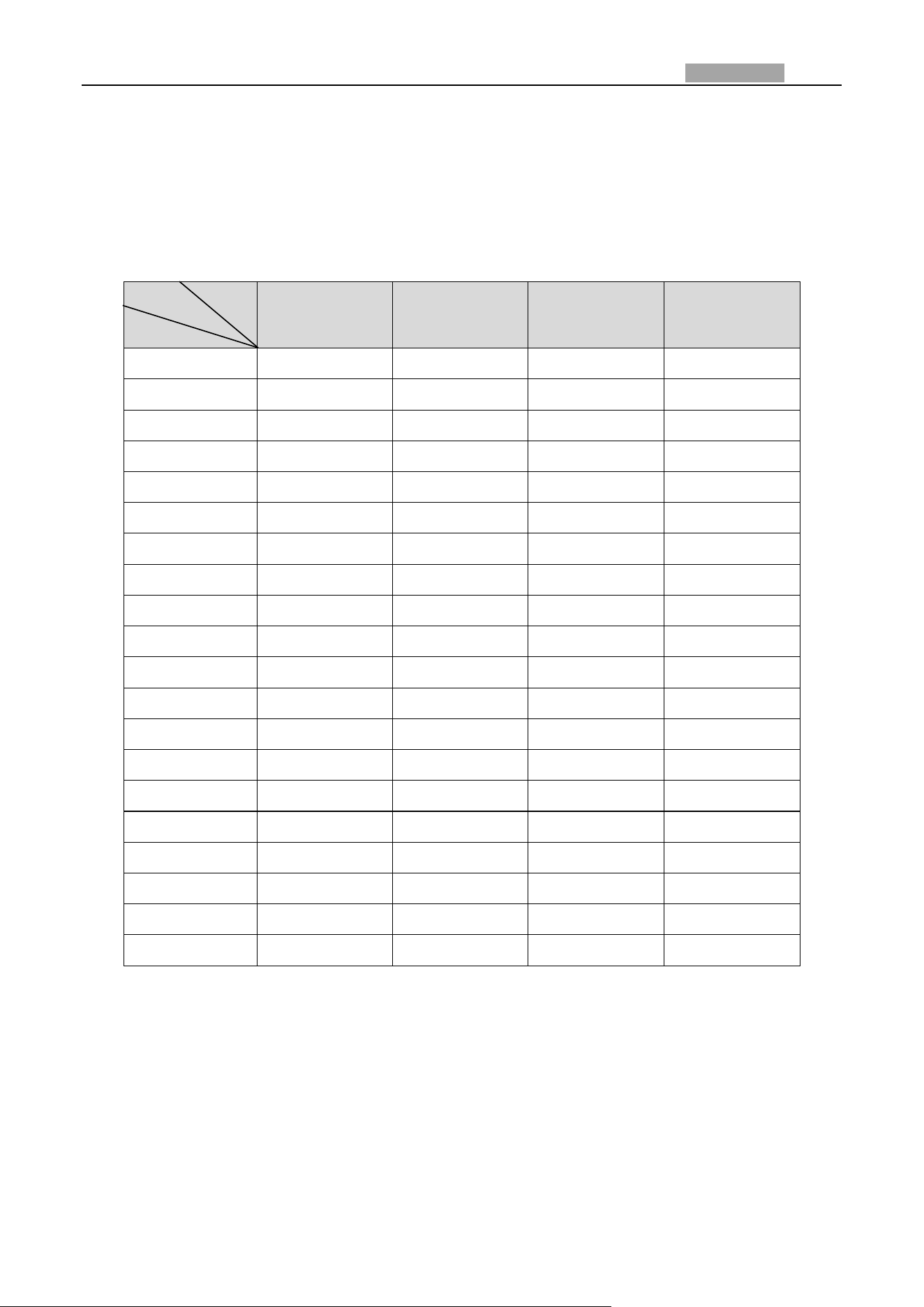
Network Speed Dome User Manual
138
Appendix 6 24VAC Wire Gauge & Transmission Distance
The following table describes the recommended max. distance adopted for the certain wire gauge
when the loss rate of 24VAC voltage is less than 10%. For the AC driven device, the maximum
voltage loss rate is 10% allowable. For example, for a device with the rating power of 80VA which is
installed at a distance of 35 feet (10m) away from the transformer, then 0.8000mm is required as
the minimum wire gauge.
0.8000
1.000
1.250
2.000
10
283(86)
451(137)
716(218)
1811(551)
20
141(42)
225(68)
358(109)
905(275)
30
94(28)
150(45)
238(72)
603(183)
40
70(21)
112(34)
179(54)
452(137)
50
56(17)
90(27)
143(43)
362(110)
60
47(14)
75(22)
119(36)
301(91)
70
40(12)
64(19)
102(31)
258(78)
80
35(10)
56(17)
89(27)
226(68)
90
31(9)
50(15)
79(24)
201(61)
100
28(8)
45(13)
71(21)
181(55)
110
25(7)
41(12)
65(19)
164(49)
120
23(7)
37(11)
59(17)
150(45)
130
21(6)
34(10)
55(16)
139(42)
140
20(6)
32(9)
51(15)
129(39)
150
18(5)
30(9)
47(14)
120(36)
160
17(5)
28(8)
44(13)
113(34)
170
16(4)
26(7)
42(12)
106(32)
180
15(4)
25(7)
39(11)
100(30)
190
14(4)
23(7)
37(11)
95(28)
200
14(4)
22(6)
35(10)
90(27)
Wire Gauge
(mm)
Distance
(feet)
Power (va)
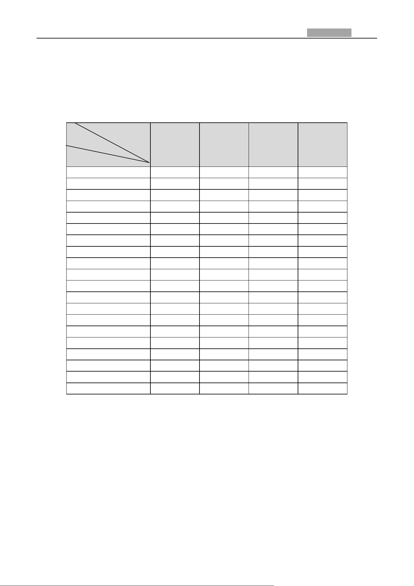
Network Speed Dome User Manual
139
Appendix 7 12VDC Wire Gauge & Transmission Distance
The following table describes the recommended max. distance adopted for the certain wire gauge
when the loss rate of 12VDC voltage is less than 15%. For the DC driven device, the maximum
voltage loss rate is 15% allowable.
0.800(20)
1.000(18)
1.250 (16)
2.000(12)
10
97(28)
153(44)
234(67)
617(176)
20
49(14)
77(22)
117(33)
308(88)
24
41(12)
64(18)
98(28)
257(73)
30
32(9)
51(15)
78(22)
206(59)
40
24(7)
38(11)
59(17)
154(44)
48
20(6)
32(9)
49(14)
128(37)
50
19(6)
31(9)
47(13)
123(35)
60
16(5)
26(7)
39(11)
103(29)
70
14(4)
22(6)
33(10)
88(25)
80
12(3)
19(5)
29(8)
77(22)
90
10.8(3.1)
17(5)
26(7)
69(20)
100
9.7(2.8)
15(4)
23(7)
62(18)
110
8.9(2.5)
14(4)
21(6)
56(16)
120
8.1(2.3)
13(4)
20(6)
51(15)
130
7.5(2.1)
11.8(3.4)
18(5)
47(14)
140
7(2)
11(3.1)
17(5)
44(13)
150
6.5(1.9)
10.2(2.9)
16(4)
41(12)
160
6.1(1.7)
9.6(2.7)
15(4)
39(11)
170
5.7(1.6)
9(2.6)
14(4)
36(10)
180
5.4(1.5)
8.5(2.4)
13(4)
34(10)
Distance
(feet)
Wire Gauge
(mm)
Power (va)

Network Speed Dome User Manual
140
Appendix 8 Table of Wire Gauge Standards
Bare Wire
Gauge(mm)
American
Wire Gauge
AWG
British Wire
Gauge SWG
Cross-sectional
Area of Bare
Wire(mm
2
)
0.750
21
0.4417
0.800
20
21
0.5027
0.900
19
20
0.6362
1.000
18
19
0.7854
1.250
16
18
1.2266
1.500
15
17
1.7663
2.000
12
14
3.1420
2.500
4.9080
3.000
7.0683
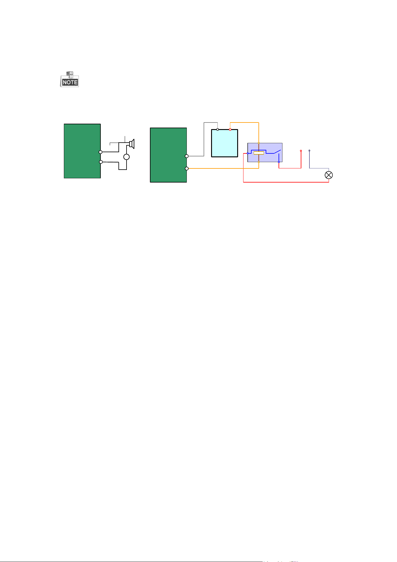
Appendix 9 Alarm In/Out Connections
This section is only for the speed domes with alarm in/out functions.
The speed dome can be connected with alarm inputs (0~5VDC) and alarm outputs.
Refer to the following diagrams for alarm output:
JQC-
3FG
Relay
30VDC
GND OUT
L N
~220V AC
Relay Output
Dome
(10 A 250VAC)
Diagram (left)
Diagram(right)
1A
OUT(n)
OUT(n)
+
-
DC
DC Load
Relay Output
Dome
OUT(n)
OUT(n)
Figure A.9.1 Alarm Out Connections
The alarm provides the relay output (no voltage), and the external power supply is
required when it connects to the alarm device.
For DC power supply (left diagram), the input voltage must be no more than
30VDC, 1A.
For AC power supply, the external relay must be used (right diagram) to prevent
damages to the speed dome and avoid risk of electric shock.
0503101050928
Network Speed Dome User Manual
142