Loading ...
Loading ...
Loading ...
Unit Installation
Page 7 mrcool.com
When installing the coil take into consideration the length of the refrigerant piping and try to minimize the distance
as much as possible. DO NOT install the air handler in a location that is either above or below the
condenser that violates any instructions/requirements of the condenser in the system it is being
installed in (consult the manuals/information provided with the condenser). Allow a minimum of 24 in
(610 mm) in front of the unit to provide clearance for service. When installing in an area directly over a finished
ceiling (such as in an attic), an emergency drain pan is required to be installed directly under the unit. Please refer
to local and state codes for requirements. When this unit is installed in area that may become wet, elevate the unit
with a sturdy, non-porous material. In installations that are in locations that may lead to physical damage (ex:
garage), it is advised to install a protective barrier to prevent such damage.
3.2 Location (cont.)
3.3 A-Coil Orientation/Position Options
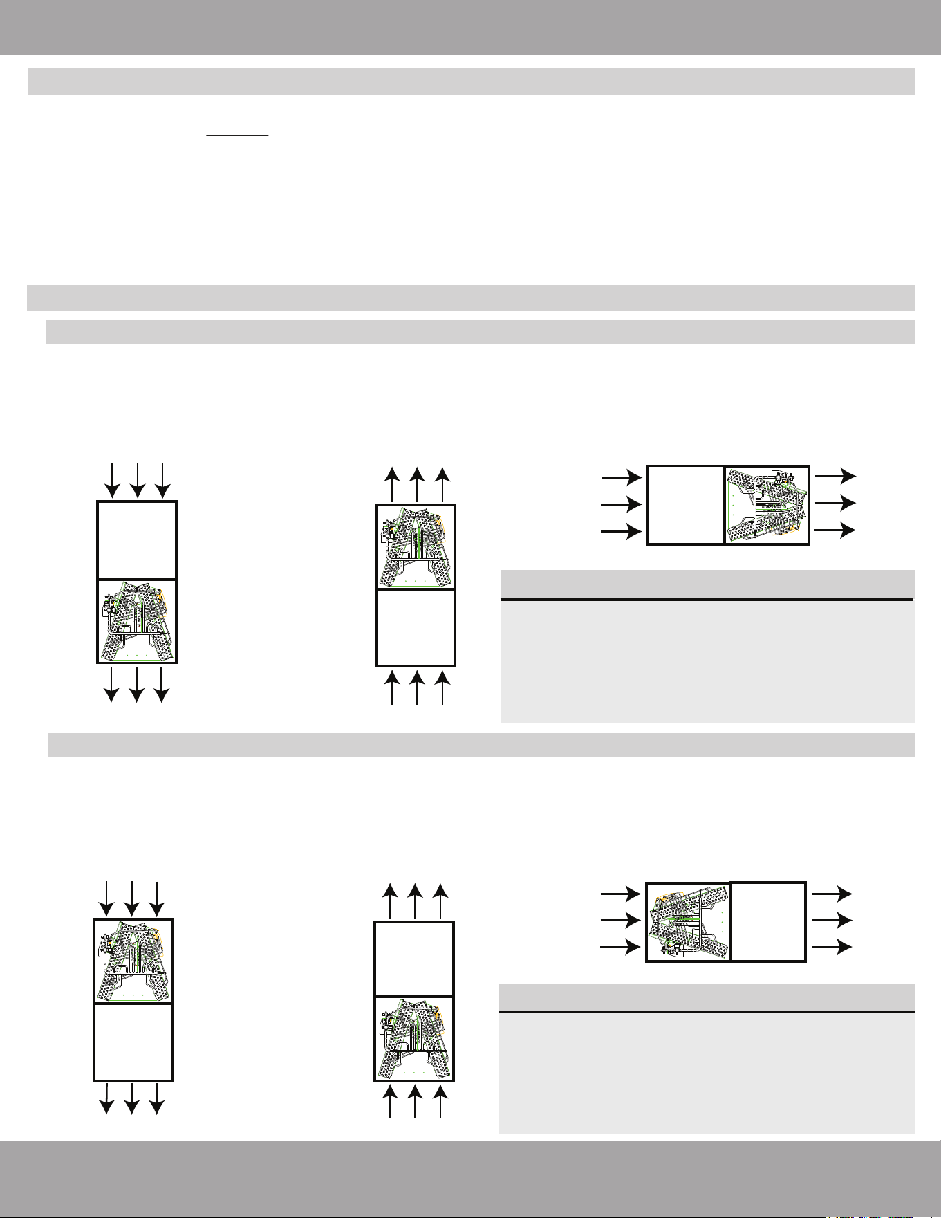
3.3.1 Installing A-Coils with a furnace
Downflow Application
Furnace
A-Coil
Return Airflow
Supply Airflow to Ductwork
Upflow Application
Furnace
A-Coil
Return Airflow
Supply Airflow to Ductwork
Horizontal Right Application
Return Airflow
Supply Airflow to Ductwork
3.3.2 Installing A-Coils with a modular blower
Downflow Application
Return Airflow
Supply Airflow to Ductwork
A-Coil
Modular
Blower
Return Airflow
Supply Airflow to Ductwork
Upflow Application
Return Airflow
Supply Airflow to Ductwork
Horizontal Right Application
When installing the Universal A-Coils in an application with a furnace, it must be installed in a position where the
return air flows through the furnace first and then the A-Coils. From the A-Coils, the airflow is then supplied to
the ductwork to be dispersed throughout the rooms.
When installing the Universal A-Coils in an application with a modular blower, it must be installed in a position
where the return air flows through the A-Coils first and then the modular blower. From the modular blower, the
airflow is then supplied to the ductwork to be dispersed throughout the rooms.
Modular
Blower
A-Coil
Depending on your application (specifically the
size of the components in your system, cabinet
opening size and A-Coil opening size, etc.) a
transition may need to be constructed so the
furnace and A-Coil can be connected together
with a smooth transition between openings.
IMPORTANT:
Depending on your application (specifically the
size of the components in the system, modular
blower opening size and A-Coil opening size, etc.)
a transition may need to be constructed so the
modular blower and A-Coil can be connected
with a smooth transition between openings.
IMPORTANT:
A-CoilFurnace
A-Coil
Modular Blower
Loading ...
Loading ...
Loading ...