Loading ...
Loading ...
Loading ...
Page 10mrcool.com
No-Vac
®
Quick Connect
®
Line Set* Installation
INSTRUCTIONS FOR USE WITH
NO-VAC™ QUICK CONNECT® LINE SET*
SOLD SEPARATELY
37 ft/lb
37 ft/lb
52 ft/lb
52 ft/lb
M1
F1
M1 F1
M2
F2
M2 F2
*1
*1
*2
*2
3/8”
3/8”
3/4”
3/4”
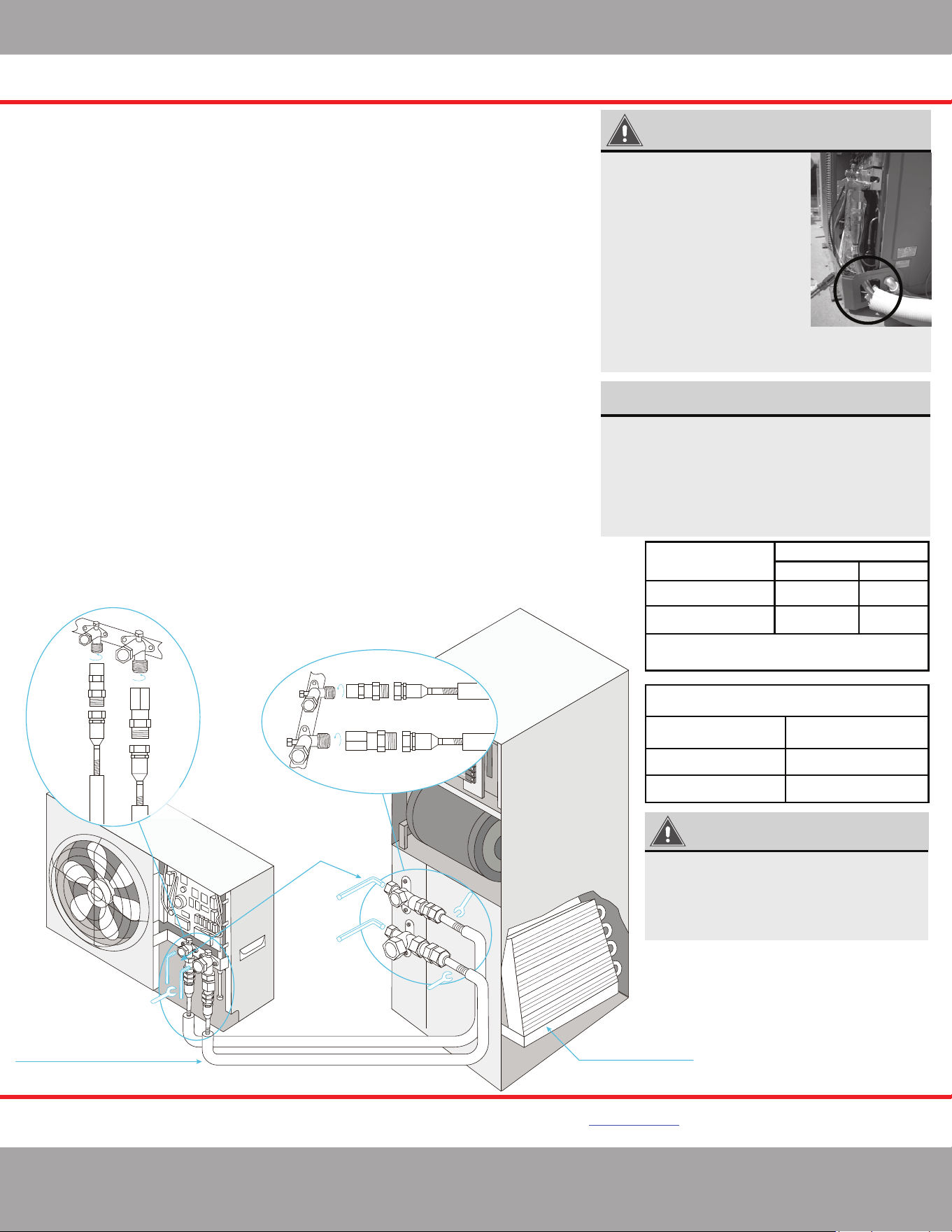
Complete unit replacement
using the No-Vac® Quick Connect® lines
Air Handler
Open the stop/cuto
valves only after
connecting the
refrigerant lines
A-coil Precharged
with R-410A Refrigerant
Connect using precharged
line set with quick connect
ttings in length 15, 25, 35, 50 feet
MRCOOL Universal Series
DC Inverter
KINK RESISTANT, PRECHARGED, SIMPLE SECURE QUICK CONNECT, 100% CONNECTION GUARANTEE
www.mrcool.com
v10-25-2021
IMPORTANT
When running the Line Set
through the knockout hole of
the condenser, it may be
necessary to slightly trim the
line set insulation so it feeds
through the hole freely.
Otherwise, it may be difficult
to connect it to the condenser.
Once the installation is
complete, pack the hole with
neoprene to prevent small
animals and insects from
entering the condenser.
Please read and follow the instruc�ons and diagram below
*
:
1.
Take out matching male connectors M1 and M2.
2.
Remove protec�ve cap with the copper gasket at each stop valve on the DC INVERTER
and ensure the threads are clean and complete.
3.
Tighten the M1 connector to the cutoff valve *1 with a �ghtening force of 37 �/lb (50 Nm).
Tighten the M2 connector to the cutoff valve *2 with a �ghtening force of 52 �/lb (70.5 Nm).
4.
Repeat step 3 for AIR HANDLER at the other end of the LINE SET.
5.
Unroll and route the LINE SET between the AIR HANDLER and the DC INVERTER. Bend the line
set by hand to route the line set to suit your applica�on. Use care when bending the line set.
Please refer to the Bending the Line Set sec�on on Pg. 11 for more detailed instruc�ons on
how to properly and safely bend refrigerant piping, as well as the correct bend radius.
6.
Remove the protec�ve caps of the valves at both ends of the LINE SET. Verify that all
threads are clean and complete.
7.
Tighten the LINE SET F1 valve to the M1 Connector (a�ached in step 3) with a force
of 33 �/lb (45 Nm). Tighten the LINE SET F2 valve to the M2 Connector (a�ached in step 3)
with a �ghtening force of 48 �/lb (65 Nm).
8. Repeat this process for the AIR HANDLER at the other end of the LINE SET.
Connec�ons must be made exactly as specified to avoid system leaks and /or damage
9.
At the OUTDOOR UNIT remove the protec�ve cap at the cutoff valve switch and open the
cutoff valve with a hex wrench to release refrigerant into the system. If there is any fizz,
grease or other leakage, then close the valve immediately and check that steps 3 and 7
were done properly. Otherwise, using a sponge or spray bo�le, apply a soapy water solu�on
to the connec�on points to check for micro leaks. If any bubbles form it indicates there is a
leak. If this does occur, close the valve immediately and check that steps 3 and 7 were done
properly and re-�ghten the valves and line set if necessary.
10. A�er the correct connec�on, re-�ghten the
cutoff
valve’s protec�on cap and cover the
M1, M2 and F1, F2 connec�ons with the gray insula�ng sleeve to help prevent
condensa�on. Then, proceed to sec�on 3.5 Condensate Removal and con�nue
the installa�on.
NOTE ON WRENCHES
The wrench sizes needed for tightening the
No-Vac
®
Quick Connect
®
Line Set are listed
below. However, based on the availability of the
wrench sizes needed, it is recommended to use
two large crescent (adjustable-type) wrenches.
Using one to hold the valve while using the
other wrench to tighten the line set connector.
IMPORTANT
The stop/cutoff valves on the unit must
be opened AFTER connecting the lines
and BEFORE turning on the unit.
Otherwise, operation can cause leakage
and/or damage to the unit.
Piping Size
(Stamped on piping)
Allen/Hex Wrench Sizes Needed
To Open Stop/Cutoff Valves
Wrench Size Required
Standard Metric
Allen Wrench Size
1”3/8”
3/8”
25 mm
1-3/8”3/4”
3/4”
35 mm
5 mm
8 mm
Piping/Valve Size
(Stamped on piping)
Or 2x large crescent (adjustable-type)
wrenches
*Pat. https://mrcool.com/mrcool-patents/
ⱡFailure to follow the instrucons provided could result in severe harm to you, this product, or other property.
The manufacturer, distributor, and seller are not responsible for any harm resulng from the failure to follow
instrucons and the failure to follow these instrucons will void any and all warranes express or implied.
Loading ...
Loading ...
Loading ...