
DS-K1TA70 Series Face Recognion Terminal
User Manual

Legal Informaon
About this Document
●
This Document includes instrucons for using and managing the Product. Pictures, charts,
images and all other informaon hereinaer are for descripon and explanaon only.
●
The informaon contained in the Document is subject to change, without noce, due to
rmware updates or other reasons. Please nd the latest version of the Document at the
Hikvision website ( hps://www.hikvision.com ). Unless otherwise agreed, Hangzhou Hikvision
Digital Technology Co., Ltd. or its aliates (hereinaer referred to as "Hikvision") makes no
warranes, express or implied.
●
Please use the Document with the guidance and assistance of professionals trained in
supporng the Product.
About this Product
●
This product can only enjoy the aer-sales service support in the country or region where the
purchase is made.
●
If the product you choose is a video product, please scan the following QR code to obtain the
"Iniaves on the Use of Video Products", and read it carefully.
Acknowledgment of Intellectual Property Rights
●
Hikvision owns the copyrights and/or patents related to the technology embodied in the
Products described in this Document, which may include licenses obtained from third pares.
●
Any part of the Document, including text, pictures, graphics, etc., belongs to Hikvision. No part
of this Document may be excerpted, copied, translated, or modied in whole or in part by any
means without wrien permission.
●
and other Hikvision's trademarks and logos are the properes of Hikvision in
various jurisdicons.
●
Other trademarks and logos menoned are the properes of their respecve owners.
LEGAL DISCLAIMER
●
TO THE MAXIMUM EXTENT PERMITTED BY APPLICABLE LAW, THIS DOCUMENT AND THE
PRODUCT DESCRIBED, WITH ITS HARDWARE, SOFTWARE AND FIRMWARE, ARE PROVIDED "AS
IS" AND "WITH ALL FAULTS AND ERRORS". HIKVISION MAKES NO WARRANTIES, EXPRESS OR
DS-K1TA70 Series Face Recognion Terminal User Manual
i

IMPLIED, INCLUDING WITHOUT LIMITATION, MERCHANTABILITY, SATISFACTORY QUALITY, OR
FITNESS FOR A PARTICULAR PURPOSE. THE USE OF THE PRODUCT BY YOU IS AT YOUR OWN RISK.
IN NO EVENT WILL HIKVISION BE LIABLE TO YOU FOR ANY SPECIAL, CONSEQUENTIAL,
INCIDENTAL, OR INDIRECT DAMAGES, INCLUDING, AMONG OTHERS, DAMAGES FOR LOSS OF
BUSINESS PROFITS, BUSINESS INTERRUPTION, OR LOSS OF DATA, CORRUPTION OF SYSTEMS, OR
LOSS OF DOCUMENTATION, WHETHER BASED ON BREACH OF CONTRACT, TORT (INCLUDING
NEGLIGENCE), PRODUCT LIABILITY, OR OTHERWISE, IN CONNECTION WITH THE USE OF THE
PRODUCT, EVEN IF HIKVISION HAS BEEN ADVISED OF THE POSSIBILITY OF SUCH DAMAGES OR
LOSS.
●
YOU ACKNOWLEDGE THAT THE NATURE OF THE INTERNET PROVIDES FOR INHERENT SECURITY
RISKS, AND HIKVISION SHALL NOT TAKE ANY RESPONSIBILITIES FOR ABNORMAL OPERATION,
PRIVACY LEAKAGE OR OTHER DAMAGES RESULTING FROM CYBER-ATTACK, HACKER ATTACK,
VIRUS INFECTION, OR OTHER INTERNET SECURITY RISKS; HOWEVER, HIKVISION WILL PROVIDE
TIMELY TECHNICAL SUPPORT IF REQUIRED.
●
YOU AGREE TO USE THIS PRODUCT IN COMPLIANCE WITH ALL APPLICABLE LAWS, AND YOU ARE
SOLELY RESPONSIBLE FOR ENSURING THAT YOUR USE CONFORMS TO THE APPLICABLE LAW.
ESPECIALLY, YOU ARE RESPONSIBLE, FOR USING THIS PRODUCT IN A MANNER THAT DOES NOT
INFRINGE ON THE RIGHTS OF THIRD PARTIES, INCLUDING WITHOUT LIMITATION, RIGHTS OF
PUBLICITY, INTELLECTUAL PROPERTY RIGHTS, OR DATA PROTECTION AND OTHER PRIVACY
RIGHTS. YOU SHALL NOT USE THIS PRODUCT FOR ANY PROHIBITED END-USES, INCLUDING THE
DEVELOPMENT OR PRODUCTION OF WEAPONS OF MASS DESTRUCTION, THE DEVELOPMENT OR
PRODUCTION OF CHEMICAL OR BIOLOGICAL WEAPONS, ANY ACTIVITIES IN THE CONTEXT
RELATED TO ANY NUCLEAR EXPLOSIVE OR UNSAFE NUCLEAR FUEL-CYCLE, OR IN SUPPORT OF
HUMAN RIGHTS ABUSES.
●
IN THE EVENT OF ANY CONFLICTS BETWEEN THIS DOCUMENT AND THE APPLICABLE LAW, THE
LATTER PREVAILS.
Data Protecon
●
To protect data, the development of Hikvision Products incorporates privacy by design
principles. For example, for Products with facial recognion features, biometrics data is stored in
your Products with encrypon method; for ngerprint Products, only ngerprint template will be
saved, which is impossible to reconstruct a ngerprint image.
●
As a data controller/processor, you may process personal data, including collecon, storage, use,
processing, disclosure, deleon, etc. You are advised to pay aenon to and comply with
applicable laws and regulaons related to the protecon of personal data, including without
limitaon, conducng security controls to safeguard personal data, such as, implemenng
reasonable administrave and physical security controls, conduct periodic reviews and the
assessments of the eecveness of your security controls.
© Hangzhou Hikvision Digital Technology Co., Ltd. All rights reserved.
DS-K1TA70 Series Face Recognion Terminal User Manual
ii
Symbol Convenons
The symbols that may be found in this document are dened as follows.
Symbol Descripon
Danger
Indicates a hazardous situaon which, if not avoided, will or could
result in death or serious injury.
Cauon
Indicates a potenally hazardous situaon which, if not avoided, could
result in equipment damage, data loss, performance degradaon, or
unexpected results.
Note
Provides addional informaon to emphasize or supplement
important points of the main text.
DS-K1TA70 Series Face Recognion Terminal User Manual
iii

Regulatory Informaon
FCC Informaon
Please take aenon that changes or modicaon not expressly approved by the party responsible
for compliance could void the user’s authority to operate the equipment.
FCC compliance: This equipment has been tested and found to comply with the limits for a Class B
digital device, pursuant to part 15 of the FCC Rules. These limits are designed to provide
reasonable protecon against harmful interference in a residenal installaon. This equipment
generates, uses and can radiate radio frequency energy and, if not installed and used in accordance
with the instrucons, may cause harmful interference to radio communicaons. However, there is
no guarantee that interference will not occur in a parcular installaon. If this equipment does
cause harmful interference to radio or television recepon, which can be determined by turning
the equipment o and on, the user is encouraged to try to correct the interference by one or more
of the following measures:
—Reorient or relocate the receiving antenna.
—Increase the separaon between the equipment and receiver.
—Connect the equipment into an outlet on a circuit dierent from that to which the receiver is
connected.
—Consult the dealer or an experienced radio/TV technician for help
This equipment should be installed and operated with a minimum distance 20cm between the
radiator and your body.
FCC Condions
This device complies with part 15 of the FCC Rules. Operaon is subject to the following two
condions:
1. This device may not cause harmful interference.
2. This device must accept any interference received, including interference that may cause
undesired operaon.
EU Conformity Statement
This product and - if applicable - the supplied accessories too are marked with "CE"
and comply therefore with the applicable harmonized European standards listed
DS-K1TA70 Series Face Recognion Terminal User Manual
iv
under the EMC Direcve 2014/30/EU, RE Direcve 2014/53/EU,the RoHS Direcve
2011/65/EU
2012/19/EU (WEEE direcve): Products marked with this symbol cannot be disposed
of as unsorted municipal waste in the European Union. For proper recycling, return
this product to your local supplier upon the purchase of equivalent new equipment,
or dispose of it at designated collecon points. For more informaon see:
www.recyclethis.info
2006/66/EC (baery direcve): This product contains a baery that cannot be
disposed of as unsorted municipal waste in the European Union. See the product
documentaon for specic baery informaon. The baery is marked with this
symbol, which may include leering to indicate cadmium (Cd), lead (Pb), or mercury
(Hg). For proper recycling, return the baery to your supplier or to a designated
collecon point. For more informaon see:www.recyclethis.info
This device complies with Industry Canada licence-exempt RSS standard(s). Operaon is subject to
the following two condions:
(1) this device may not cause interference, and
(2) this device must accept any interference, including interference that may cause undesired
operaon of the device.
Le présent appareil est conforme aux CNR d'Industrie Canada applicables aux appareils
radioexempts de licence. L'exploitaon est autorisée aux deux condions suivantes :
(1) l'appareil ne doit pas produire de brouillage, et
(2) l'ulisateur de l'appareil doit accepter tout brouillage radioélectrique subi, même si le
brouillage est suscepble d'en compromere le fonconnement.
DS-K1TA70 Series Face Recognion Terminal User Manual
v
Safety Instrucon
These instrucons are intended to ensure that user can use the product correctly to avoid danger
or property loss.
The precauon measure is divided into Dangers and Cauons:
Dangers: Neglecng any of the warnings may cause serious injury or death.
Cauons: Neglecng any of the cauons may cause injury or equipment damage.
Dangers: Follow these safeguards to prevent
serious injury or death.
Cauons: Follow these precauons to prevent
potenal injury or material damage.
Danger:
●
All the electronic operaon should be strictly compliance with the electrical safety regulaons,
re prevenon regulaons and other related regulaons in your local region.
●
Please use the power adapter, which is provided by normal company. This equipment is
intended to be supplied from the Class 2 surge protected power source rated 12 VDC, 2 A.
●
Do not connect several devices to one power adapter as adapter overload may cause over-heat
or re hazard.
●
Please make sure that the power has been disconnected before you wire, install or dismantle the
device.
●
When the product is installed on wall or ceiling, the device shall be rmly xed.
●
If smoke, odors or noise rise from the device, turn o the power at once and unplug the power
cable, and then please contact the service center.
●
Do not ingest baery, Chemical Burn Hazard.
This product contains a coin/buon cell baery. If the coin/buon cell baery is swallowed, it
can cause severe internal burns in just 2 hours and can lead to death.
Keep new and used baeries away from children. If the baery compartment does not close
securely, stop using the product and keep it away from children. If you think baeries might have
been swallowed or placed inside any part of the body, seek immediate medical aenon.
●
If the product does not work properly, please contact your dealer or the nearest service center.
Never aempt to disassemble the device yourself. (We shall not assume any responsibility for
problems caused by unauthorized repair or maintenance.)
DS-K1TA70 Series Face Recognion Terminal User Manual
vi

Cauons:
●
Do not drop the device or subject it to physical shock, and do not expose it to high
electromagnesm radiaon. Avoid the equipment installaon on vibraons surface or places
subject to shock (ignorance can cause equipment damage).
●
Do not place the device in extremely hot (refer to the specicaon of the device for the detailed
operang temperature), cold, dusty or damp locaons, and do not expose it to high
electromagnec radiaon.
●
The device cover for indoor use shall be kept from rain and moisture.
●
Exposing the equipment to direct sun light, low venlaon or heat source such as heater or
radiator is forbidden (ignorance can cause re danger).
●
Do not aim the device at the sun or extra bright places. A blooming or smear may occur
otherwise (which is not a malfuncon however), and aecng the endurance of sensor at the
same me.
●
Please use the provided glove when open up the device cover, avoid direct contact with the
device cover, because the acidic sweat of the ngers may erode the surface coang of the device
cover.
●
Please use a so and dry cloth when clean inside and outside surfaces of the device cover, do
not use alkaline detergents.
●
Please keep all wrappers aer unpack them for future use. In case of any failure occurred, you
need to return the device to the factory with the original wrapper. Transportaon without the
original wrapper may result in damage on the device and lead to addional costs.
●
Improper use or replacement of the baery may result in hazard of explosion. Replace with the
same or equivalent type only. Dispose of used baeries according to the instrucons provided by
the baery manufacturer.
●
Biometric recognion products are not completely applicable to an-spoong environments. If
you require a higher security level, use mulple authencaon modes.
●
Working temperature: 0 °C to 50 °C; Working humidity: 10% to 90% (no condensing)
●
Indoor use. The device should be at least 2 meters away from the light, and at least 3 meters
away from the window.
●
Version: 1.0, Issue Date: 20200519
●
Outdoor use or use in environment exceeding the device temperature measurement will aect
the temperature measurement accuracy.
DS-K1TA70 Series Face Recognion Terminal User Manual
vii

Available Models
Product Name Model
Face Recognion Terminal DS-K1TA70MI-T
Use only power supplies listed in the user instrucons:
Model Manufacturer Standard
C2000IC12.0-24P-DE MOSO Power Supply
Technology Co., Ltd.
CEE
C2000IC12.0-24P-GB MOSO Power Supply
Technology Co., Ltd.
BS
KPL-040F-VI Channel Well Technology Co
Ltd.
CEE
DS-K1TA70 Series Face Recognion Terminal User Manual
viii

Contents
Chapter 1 Overview .................................................................................................................... 1
1.1 Overview ................................................................................................................................ 1
1.2 Features ................................................................................................................................. 1
Chapter 2 Appearance ................................................................................................................ 3
Chapter 3 Installaon ................................................................................................................. 6
3.1 Installaon Environment ........................................................................................................ 6
3.2 Flush Mounng ...................................................................................................................... 6
3.3 Surface Mounng .................................................................................................................. 9
Chapter 4 Wiring ...................................................................................................................... 13
4.1 Terminal Descripon ............................................................................................................ 13
4.2 Wire Normal Device ............................................................................................................. 16
4.3 Wire Secure Door Control Unit ............................................................................................ 17
4.4 Wire Fire Module ................................................................................................................. 17
4.4.1 Wiring Diagram of Door Open When Powering O .................................................... 17
4.4.2 Wiring Diagram of Door Locked When Powering O .................................................. 20
Chapter 5 Acvaon ................................................................................................................. 22
5.1 Acvate via Device ............................................................................................................... 22
5.2 Acvate via SADP ................................................................................................................. 24
5.3 Acvate Device via Client Soware ...................................................................................... 25
5.4 Acvate via Web Browser .................................................................................................... 26
Chapter 6 Quick Operaon ....................................................................................................... 27
6.1 Select Language ................................................................................................................... 27
6.2 Set Applicaon Mode .......................................................................................................... 29
6.3 Set Network Parameters ...................................................................................................... 30
6.4 Set Administrator ................................................................................................................. 30
Chapter 7 Basic Operaon ........................................................................................................ 33
DS-K1TA70 Series Face Recognion Terminal User Manual
ix

7.1 Login .................................................................................................................................... 33
7.1.1 Login by Administrator ................................................................................................ 33
7.1.2 Login by Acvaon Password ...................................................................................... 36
7.2 Communicaon Sengs ...................................................................................................... 37
7.2.1 Set Wired Network Parameters .................................................................................. 38
7.2.2 Set RS-485 Parameters ................................................................................................ 39
7.2.3 Set Wiegand Parameters ............................................................................................. 40
7.3 User Management ............................................................................................................... 41
7.3.1 Add Administrator ....................................................................................................... 41
7.3.2 Add Face Picture ......................................................................................................... 42
7.3.3 Add Card ..................................................................................................................... 44
7.3.4 View Password ............................................................................................................ 45
7.3.5 Set Authencaon Mode ............................................................................................ 46
7.3.6 Search and Edit User ................................................................................................... 46
7.4 Data Management ............................................................................................................... 47
7.4.1 Delete Data ................................................................................................................. 47
7.4.2 Import Data ................................................................................................................. 47
7.4.3 Export Data ................................................................................................................. 48
7.5 Identy Authencaon ........................................................................................................ 48
7.5.1 Authencate via Single Credenal .............................................................................. 48
7.5.2 Authencate via Mulple Credenal .......................................................................... 49
7.6 Basic Sengs ....................................................................................................................... 49
7.7 Set Biometric Parameters .................................................................................................... 52
7.8 Set Access Control Parameters ............................................................................................ 54
7.9 Time and Aendance Status Sengs .................................................................................. 55
7.9.1 Disable Aendance Mode via Device ......................................................................... 55
7.9.2 Set Manual Aendance via Device ............................................................................. 56
7.9.3 Set Auto Aendance via Device .................................................................................. 57
DS-K1TA70 Series Face Recognion Terminal User Manual
x

7.9.4 Set Manual and Auto Aendance via Device .............................................................. 59
7.10 System Maintenance .......................................................................................................... 60
7.11 Video Intercom .................................................................................................................. 62
7.11.1 Call Client Soware from Device ............................................................................... 62
7.11.2 Call Center from Device ............................................................................................ 63
7.11.3 Call Device from Client Soware ............................................................................... 63
7.11.4 Call Room from Device .............................................................................................. 64
7.11.5 Call Mobile Client from Device .................................................................................. 64
7.12 Temperature Measurement Sengs ................................................................................. 65
Chapter 8 Operaon via Web Browser ...................................................................................... 68
8.1 Login .................................................................................................................................... 68
8.2 Live View .............................................................................................................................. 68
8.3 Person Management ............................................................................................................ 70
8.4 Search Event ........................................................................................................................ 71
8.5 Conguraon ....................................................................................................................... 71
8.5.1 Set Local Parameters ................................................................................................... 71
8.5.2 View Device Informaon ............................................................................................. 72
8.5.3 Set Time ...................................................................................................................... 72
8.5.4 Set DST ........................................................................................................................ 73
8.5.5 View Open Source Soware License ........................................................................... 73
8.5.6 Upgrade and Maintenance ......................................................................................... 73
8.5.7 Log Query .................................................................................................................... 75
8.5.8 Security Mode Sengs ............................................................................................... 75
8.5.9 Cercate Management ............................................................................................. 76
8.5.10 Change Administrator's Password ............................................................................. 77
8.5.11 View Device Arming/Disarming Informaon ............................................................ 77
8.5.12 Network Sengs ....................................................................................................... 77
8.5.13 Set Video and Audio Parameters .............................................................................. 81
DS-K1TA70 Series Face Recognion Terminal User Manual
xi

8.5.14 Customize Audio Content ......................................................................................... 82
8.5.15 Set Image Parameters ............................................................................................... 83
8.5.16 Set Supplement Light Brightness .............................................................................. 85
8.5.17 Time and Aendance Sengs .................................................................................. 85
8.5.18 Set Video Intercom Parameters ................................................................................ 88
8.5.19 Access Control Sengs ............................................................................................. 90
8.5.20 Set Biometric Parameters ......................................................................................... 97
8.5.21 Set Noce Publicaon ............................................................................................. 100
8.5.22 Temperature Measurement Sengs ...................................................................... 101
Chapter 9 Client Soware Conguraon ................................................................................. 104
9.1 Conguraon Flow of Client Soware ............................................................................... 104
9.2 Device Management .......................................................................................................... 104
9.2.1 Add Device ................................................................................................................ 105
9.2.2 Reset Device Password ............................................................................................. 113
9.3 Group Management ........................................................................................................... 114
9.3.1 Add Group ................................................................................................................. 114
9.3.2 Import Resources to Group ....................................................................................... 115
9.3.3 Edit Resource Parameters ......................................................................................... 115
9.3.4 Remove Resources from Group ................................................................................ 115
9.4 Person Management .......................................................................................................... 116
9.4.1 Add Organizaon ...................................................................................................... 116
9.4.2 Congure Basic Informaon ..................................................................................... 117
9.4.3 Issue a Card to One Person ....................................................................................... 117
9.4.4 Upload a Face Photo from Local PC .......................................................................... 118
9.4.5 Take a Photo via Client .............................................................................................. 119
9.4.6 Collect Face via Access Control Device ..................................................................... 120
9.4.7 Congure Access Control Informaon ...................................................................... 121
9.4.8 Customize Person Informaon .................................................................................. 123
DS-K1TA70 Series Face Recognion Terminal User Manual
xii

9.4.9 Congure Resident Informaon ................................................................................ 124
9.4.10 Congure Addional Informaon ........................................................................... 124
9.4.11 Import and Export Person Idenfy Informaon ...................................................... 125
9.4.12 Import Person Informaon ..................................................................................... 125
9.4.13 Import Person Pictures ........................................................................................... 125
9.4.14 Export Person Informaon ...................................................................................... 126
9.4.15 Export Person Pictures ............................................................................................ 126
9.4.16 Delete Registered Pictures ...................................................................................... 127
9.4.17 Get Person Informaon from Access Control Device .............................................. 127
9.4.18 Move Persons to Another Organizaon .................................................................. 128
9.4.19 Issue Cards to Persons in Batch ............................................................................... 128
9.4.20 Report Card Loss ..................................................................................................... 129
9.4.21 Set Card Issuing Parameters .................................................................................... 129
9.5 Congure Schedule and Template ..................................................................................... 130
9.5.1 Add Holiday ............................................................................................................... 130
9.5.2 Add Template ............................................................................................................ 131
9.6 Set Access Group to Assign Access Authorizaon to Persons ............................................ 133
9.7 Congure Advanced Funcons .......................................................................................... 135
9.7.1 Congure Device Parameters .................................................................................... 135
9.7.2 Congure Remaining Open/Closed ........................................................................... 140
9.7.3 Congure Mul-Factor Authencaon ..................................................................... 142
9.7.4 Congure Card Reader Authencaon Mode and Schedule .................................... 144
9.7.5 Congure First Person In ........................................................................................... 146
9.7.6 Congure An-Passback ........................................................................................... 147
9.7.7 Congure Device Parameters .................................................................................... 148
9.8 Congure Linkage Acons for Access Control .................................................................... 154
9.8.1 Congure Client Acons for Access Event ................................................................. 154
9.8.2 Congure Device Acons for Access Event ............................................................... 155
DS-K1TA70 Series Face Recognion Terminal User Manual
xiii

9.8.3 Congure Device Acons for Card Swiping ............................................................... 156
9.8.4 Congure Device Acons for Person ID .................................................................... 158
9.9 Door Control ...................................................................................................................... 159
9.9.1 Control Door Status ................................................................................................... 159
9.9.2 Check Real-Time Access Records .............................................................................. 160
9.10 Event Center .................................................................................................................... 161
9.10.1 Enable Receiving Event from Devices ..................................................................... 161
9.10.2 View Real-Time Events ............................................................................................ 162
9.10.3 Search Historical Events .......................................................................................... 164
9.11 Time and Aendance ....................................................................................................... 167
9.11.1 Congure Aendance Parameters .......................................................................... 167
9.11.2 Add General Timetable ........................................................................................... 174
9.11.3 Add Shi .................................................................................................................. 177
9.11.4 Manage Shi Schedule ........................................................................................... 180
9.11.5 Manually Correct Check-in/out Record ................................................................... 183
9.11.6 Add Leave and Business Trip ................................................................................... 184
9.11.7 Calculate Aendance Data ...................................................................................... 185
9.11.8 Aendance Stascs .............................................................................................. 187
9.12 System Conguraon ....................................................................................................... 190
9.12.1 Set General Parameters .......................................................................................... 190
9.12.2 Set Picture Storage .................................................................................................. 191
9.12.3 Set Alarm Sound ..................................................................................................... 192
9.12.4 Set Access Control and Video Intercom Parameters ............................................... 192
9.12.5 Set File Saving Path ................................................................................................. 193
9.12.6 Set Email Parameters .............................................................................................. 193
9.13 Operaon and Maintenance ............................................................................................ 194
9.14 Remote Conguraon (Web) ........................................................................................... 194
9.14.1 View Device Informaon ......................................................................................... 195
DS-K1TA70 Series Face Recognion Terminal User Manual
xiv

9.14.2 Change Device Password ........................................................................................ 196
9.14.3 Time Management .................................................................................................. 196
9.14.4 System Maintenance ............................................................................................... 197
9.14.5 Congure RS-485 Parameters ................................................................................. 198
9.14.6 Security Mode Sengs ........................................................................................... 199
9.14.7 Network Parameters Sengs ................................................................................. 199
9.14.8 Report Strategy Sengs .......................................................................................... 199
9.14.9 Network Center Parameters Sengs ...................................................................... 200
9.14.10 Congure SIP Parameters ...................................................................................... 200
9.14.11 Set Relay Parameters ............................................................................................ 200
9.14.12 Set Access Control Parameters ............................................................................. 201
9.14.13 Set Face Recognion Terminal Parameters ........................................................... 201
9.14.14 Congure Face Picture Parameters ....................................................................... 202
9.14.15 Congure Supplement Light Parameters .............................................................. 203
9.14.16 Set Device No. ....................................................................................................... 204
9.14.17 Congure Video and Audio Parameters ................................................................ 204
9.14.18 Congure Volume Input or Output ....................................................................... 204
9.14.19 Operate Relay ........................................................................................................ 204
9.14.20 View Relay Status .................................................................................................. 204
Appendix A. Tips When Collecng/Comparing Face Picture .................................................... 206
Appendix B. Tips for Installaon Environment ........................................................................ 208
Appendix C. Dimension .......................................................................................................... 209
Appendix D. Communicaon Matrix and Device Command .................................................... 210
DS-K1TA70 Series Face Recognion Terminal User Manual
xv

Chapter 1 Overview
1.1 Overview
Face recognion terminal is a kind of access control device for face recognion, which is mainly
applied in security access control systems, such as logisc centers, airports, university campuses,
alarm centrals, dwellings, etc.
Note
This device is NOT for medical use.
1.2 Features
●
Supports Vanadium Oxide uncooled sensor to measure target's temperature
●
Temperature measuring range: 30 °C to 45 °C (86 °F to 113 °F), accuracy: 0.1 °C, deviaon:
± 0.5 °C
●
Recognion distance: 0.3 to 1.8 m
●
Fast temperature measurement mode: Detects face and takes temperature without identy
authencaon.
●
Mulple authencaon modes are available: card and temperature, face and temperature, card
and face and temperature, etc.
●
Face mask wearing alert
If the recognizing face does not wear a mask, the device will prompt a voice reminder. At the
same me, the authencaon or aendance is valid.
●
Forced mask wearing alert
If the recognizing face does not wear a mask, the device will prompt a voice reminder. At the
same me, the authencaon or aendance will be failed.
●
Displays temperature measurement results on the authencaon page
●
Triggers voice prompt when detecng abnormal temperature
●
Congurable door status (open/close) when detecng abnormal temperature
●
Transmits online and oine temperature informaon to the client soware via TCP/IP
communicaon and saves the data on the client soware
●
Face recognion duraon < 0.2 s/User; face recognion accuracy rate ≥ 99%
●
50,000 face capacity, 50,000 card capacity, and 100,000 event capacity
●
Suggested height for face recognion: between 1.4 m and 1.9 m
●
Supports 6 aendance status, including check in, check out, break in, break out, overme in,
overme out
●
Watchdog design and tamper funcon
●
Audio prompt for authencaon result
●
NTP, manually me synchronizaon, and auto synchronizaon
●
Connects to external access controller or Wiegand card reader via Wiegand protocol
DS-K1TA70 Series Face Recognion Terminal User Manual
1

●
Connects to secure door control unit via RS-485 protocol to avoid the door opening when the
terminal is destroyed
●
Imports and export data to the device from the client soware
●
Supports simple theme
●
Supports conguraon via Web
●
Supports ISUP 5.0
DS-K1TA70 Series Face Recognion Terminal User Manual
2

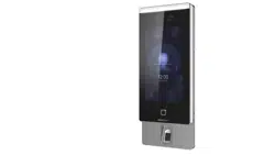
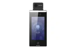
Chapter 2 Appearance
Refer to the following contents for detailed informaon of the face recognion terminal:
DS-K1TA70 Series Face Recognion Terminal User Manual
3
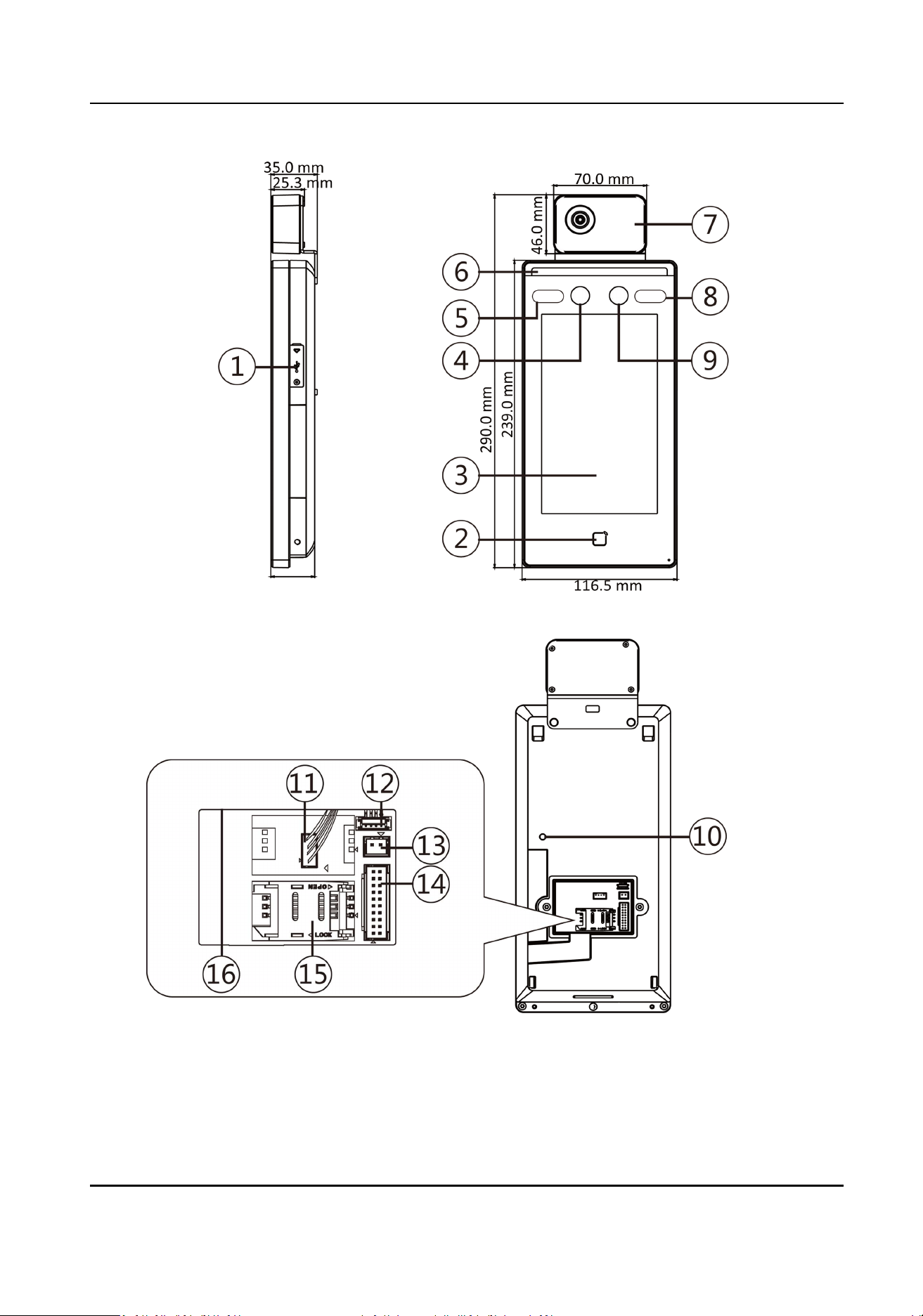
Figure 2-1 Face Recognion Terminal Diagram
DS-K1TA70 Series Face Recognion Terminal User Manual
4

Table 2-1 Descripon of Face Recognion Terminal
No. Name
1 USB Interface
2 Card Swiping Area
3 Touch Screen
4 Camera
5 IR Light
6 White Light
7 Thermographic Module
8 IR Light
9 Camera
10 TAMPER
11 Thermographic Module Interface
12 Debugging Port
13 Power Interface
14 Wiring Terminals
15 PSAM Card Slot (Reserved)
16 Network Interface
DS-K1TA70 Series Face Recognion Terminal User Manual
5

Chapter 3 Installaon
3.1 Installaon Environment
●
Avoid backlight, direct sunlight, and indirect sunlight.
●
For beer face recognion, there should be light source in or near the installaon environment.
●
Sunlight, wind, hot/cool air from air condioner and other external factors, which may aect
temperature, will create the deviaon of the temperature measurement. In order to get an
accurate result, make sure the device is applied indoors and windlessly (where is relavely
isolated from the outdoors). The working temperature should keep between 10 °C and 35 °C. If
there are no suitable environments for temperature measurement (the area faces the indoor
and connects the outdoor, the area at the door of the indoor environment, etc.), building a
temporary temperature measurement environment is suggested.
●
Inuence Factors of Temperature Measurement:
Wind: The wind will take the heat away, which may aect the measurement result.
Sweat: The sweat will take the heat away, which may aect the measurement result.
Air Condioner (Cool Air): If the indoor temperature is low, the temperature may also lower than
the actual temperature, which may aect the measurement result.
Air Condioner (Heat) or Heang: If the indoor temperature is high, the temperature may also
higher than the actual temperature, which may aect the measurement result.
●
In order to make the device work properly, you should wait for 90 min aer the device is
powered on.
●
For details about installaon environment, see Tips for Installaon Environment .
3.2 Flush Mounng
Steps
1.
Install a gang box.
2.
Connect the thermographic module and the main body.
DS-K1TA70 Series Face Recognion Terminal User Manual
6
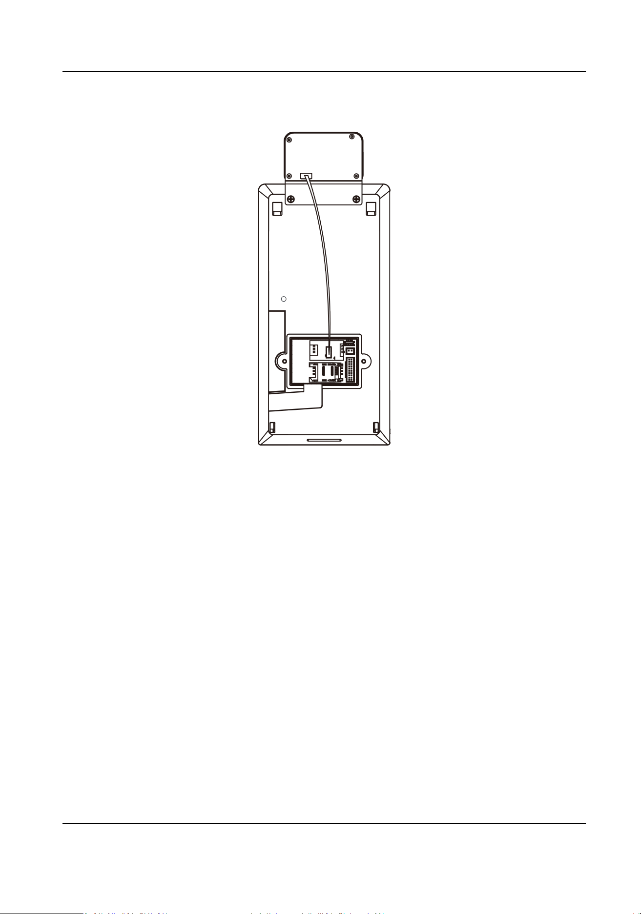
Figure 3-1 Connect Thermographic Module
3.
Use 5 supplied screws (4_KA4×22-SUS) to secure the mounng plate on the gang box.
4.
Route the cable through the cable hole of the mounng plate, and connect to corresponding
external devices' cables.
5.
Align the device with the mounng plate and hang the device on the mounng plate. Make sure
the two sheets on each side of the mounng plate have been in the slots at the back of the
device.
DS-K1TA70 Series Face Recognion Terminal User Manual
7
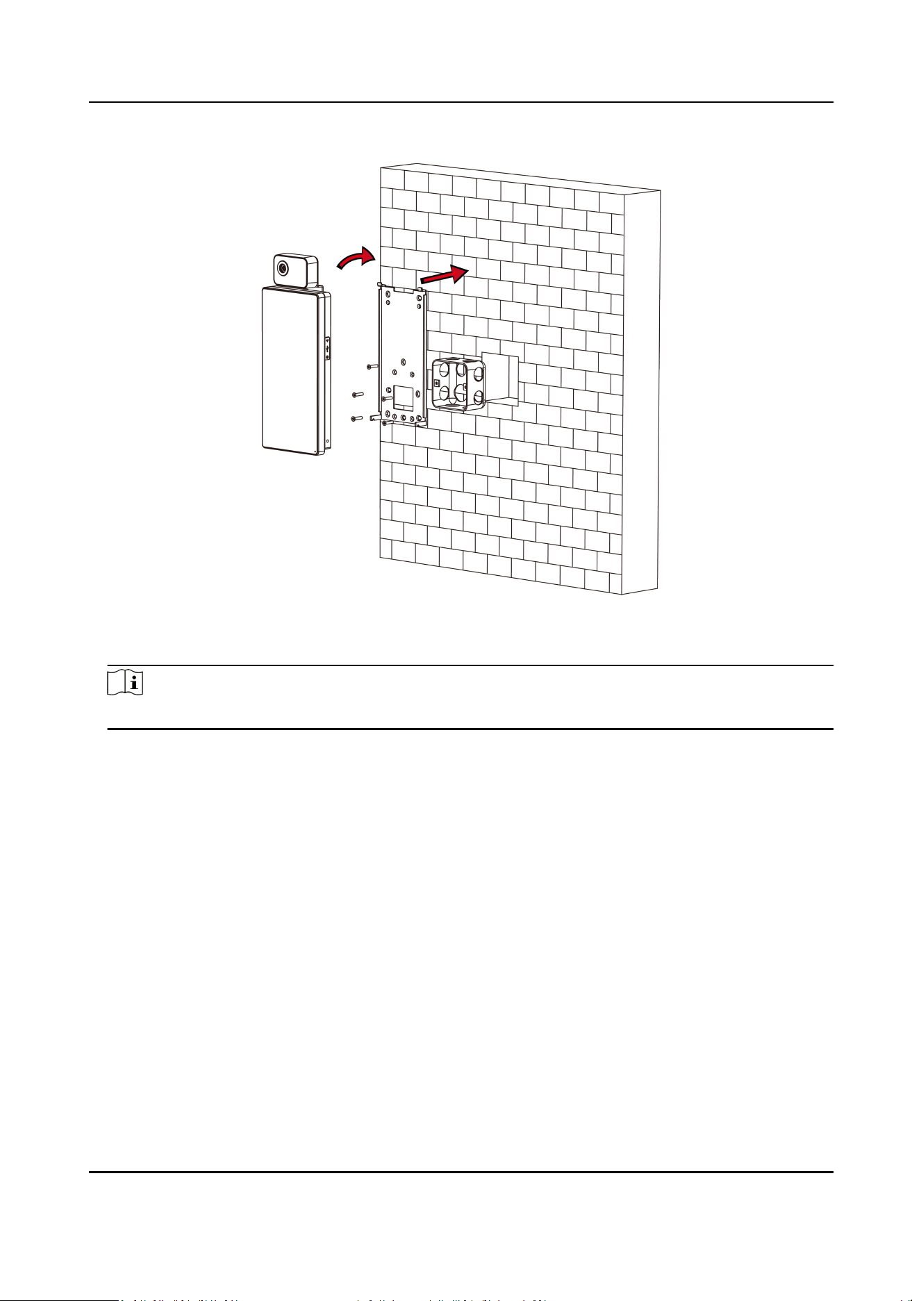
Figure 3-2 Install Device
6.
Use 2 supplied screws (SC-M4×14.5TP10-SUS) to secure the device and the mounng plate.
Note
When the screw's head is beneath the device surface, the device is secured.
DS-K1TA70 Series Face Recognion Terminal User Manual
8

Figure 3-3 Secure Device
Note
●
The installaon height here is the recommended height. You can change it according to your
actual needs.
●
For easy installaon, drill holes on mounng surface according to the supplied mounng
template.
7.
Aer installaon, for the proper use of the device (outdoor use), sck the protecon lm (parts
of models supplied) on the screen.
3.3 Surface Mounng
Steps
1.
According to the datum line on the mounng template, sck the mounng template on the wall
or other surface, 1.4 meters higher than the ground.
DS-K1TA70 Series Face Recognion Terminal User Manual
9
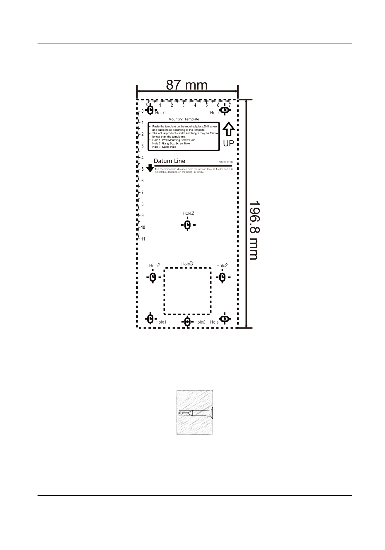
Figure 3-4 Mounng Template
2.
Drill 5 holes on the wall or other surface according to the mounng template.
3.
Insert the screw sockets of the setscrews in the drilled holes.
Figure 3-5 Insert Screw Socket
4.
Align the 6 holes to the mounng plate with the drilled holes.
DS-K1TA70 Series Face Recognion Terminal User Manual
10
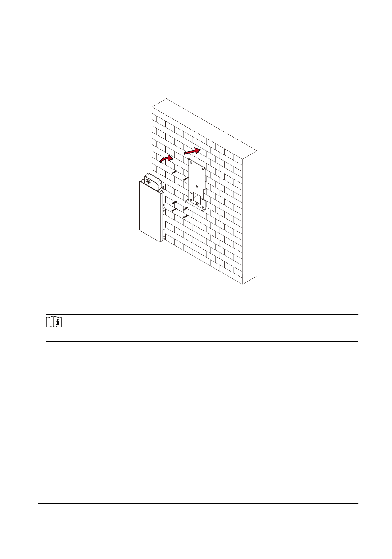
5.
Route the cable through the cable hole of the mounng plate, and connect to corresponding
external devices' cables.
6.
Align the device with the mounng plate and hang the device on the mounng plate.
Figure 3-6 Install Device
7.
Use 2 supplied screws (SC-M4×14.5TP10-SUS) to secure the device and the mounng plate.
Note
When the screw's head is beneath the device surface, the device is secured.
DS-K1TA70 Series Face Recognion Terminal User Manual
11
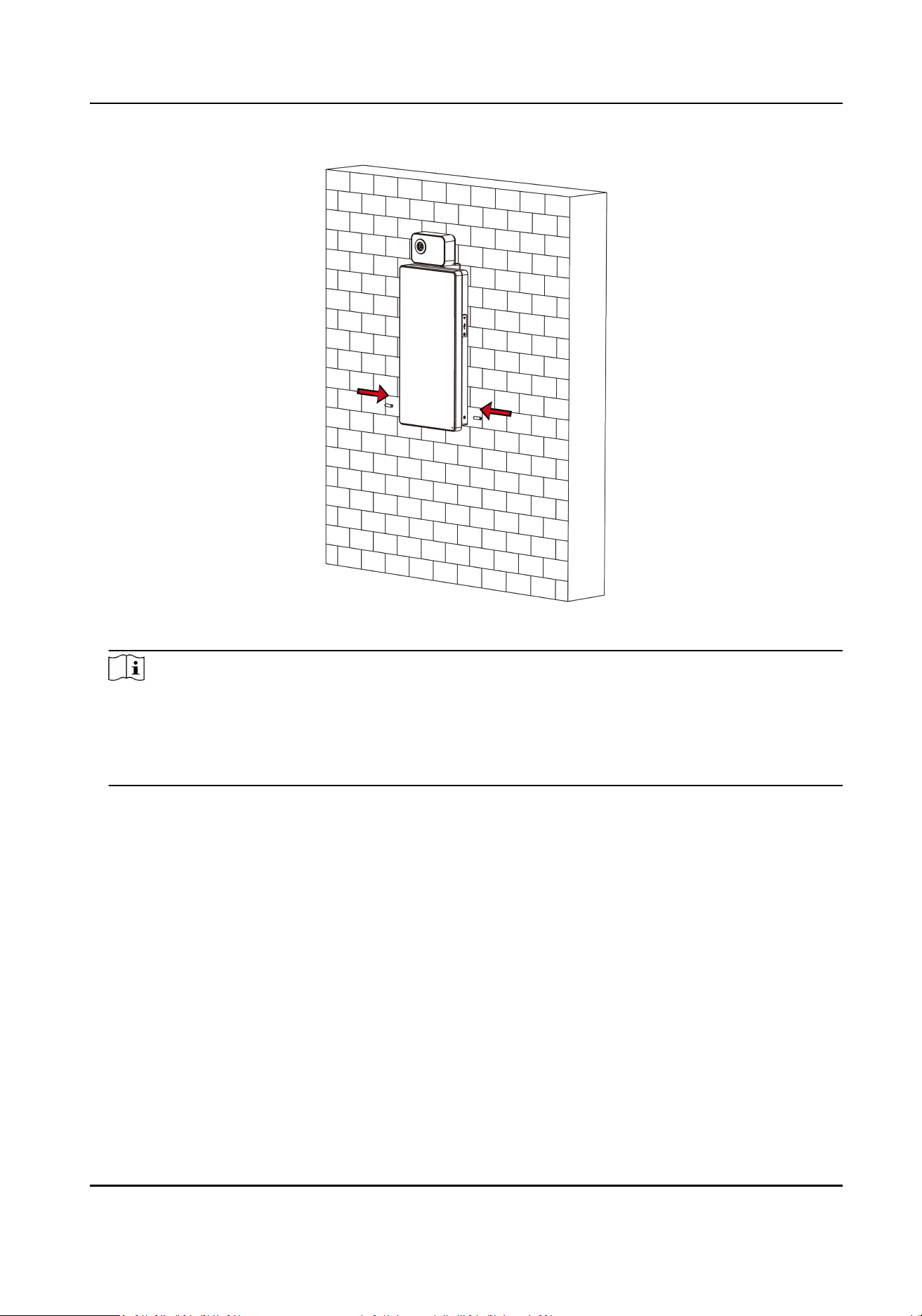
Figure 3-7 Secure Device
Note
●
The installaon height here is the recommended height. You can change it according to your
actual needs.
●
For easy installaon, drill holes on mounng surface according to the supplied mounng
template.
8.
Aer installaon, for the proper use of the device (outdoor use), sck the protecon lm (parts
of models supplied) on the screen.
DS-K1TA70 Series Face Recognion Terminal User Manual
12
Chapter 4 Wiring
You can connect the RS-485 terminal with the RS-485 card reader, connect the NC and COM
terminal with the door lock, connect the SENSOR terminal with the door contact, the BTN/GND
terminal with the exit buon, connect the alarm output and input terminal with the alarm output/
input devices, and connect the Wiegand terminal with the Wiegand card reader or the access
controller.
If connect the WIEGAND terminal with the access controller, the face recognion terminal can
transmit the authencaon informaon to the access controller and the access controller can
judge whether to open the door or not.
Note
●
If cable size is 18 AWG, you should use a 12 V power supply. And the distance between the
power supply and the device should be no more than 20 m.
●
If the cable size is 15 AWG, you should use a 12 V power supply. And the distance between the
power supply and the device should be no more than 30 m.
●
If the cable size is 12 AWG, you should use a 12 V power supply. And the distance between the
power supply and the device should be no more than 40 m.
4.1 Terminal Descripon
The terminals contains power input, alarm input, alarm output, RS-485, Wiegand output, and door
lock.
The terminal's diagram is as follows:
DS-K1TA70 Series Face Recognion Terminal User Manual
13
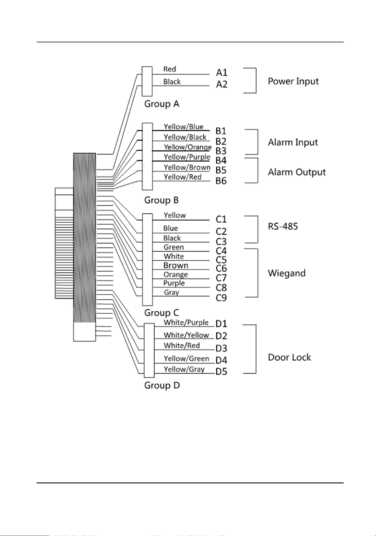
Figure 4-1 Terminal Diagram
The descripons of the terminals are as follows:
DS-K1TA70 Series Face Recognion Terminal User Manual
14

Table 4-1 Terminal Descripons
Group No. Funcon Color Name Descripon
Group A A1 Power Input Red +12 V 12 VDC Power
Supply
A2 Black GND Ground
Group B B1 Alarm Input Yellow/Blue IN1 Alarm Input 1
B2 Yellow/Black GND Ground
B3 Yellow/Orange IN2 Alarm Input 2
B4 Alarm Output Yellow/Purple NC Alarm Output
Wiring
B5 Yellow/Brown COM
B6 Yellow/Red NO
Group C C1 RS-485 Yellow 485+ RS-485 Wiring
C2 Blue 485-
C3 Black GND Ground
C4 Wiegand Green W0 Wiegand
Wiring 0
C5 White W1 Wiegand
Wiring 1
C6 Brown WG_OK Wiegand
Authencated
C7 Orange WG_ERR Wiegand
Authencaon
Failed
C8 Purple BUZZER Buzzer Wiring
C9 Gray TAMPER Tampering
Alarm Wiring
Group D D1 Door Lock White/Purple NC Lock Wiring
(NC)
D2 White/Yellow COM Common
D3 White/Red NO Lock Wiring
(NO)
DS-K1TA70 Series Face Recognion Terminal User Manual
15
Group No. Funcon Color Name Descripon
D4 Yellow/Green SENSOR Door Contact
D5 Yellow/Gray BTN Exit Door
Wiring
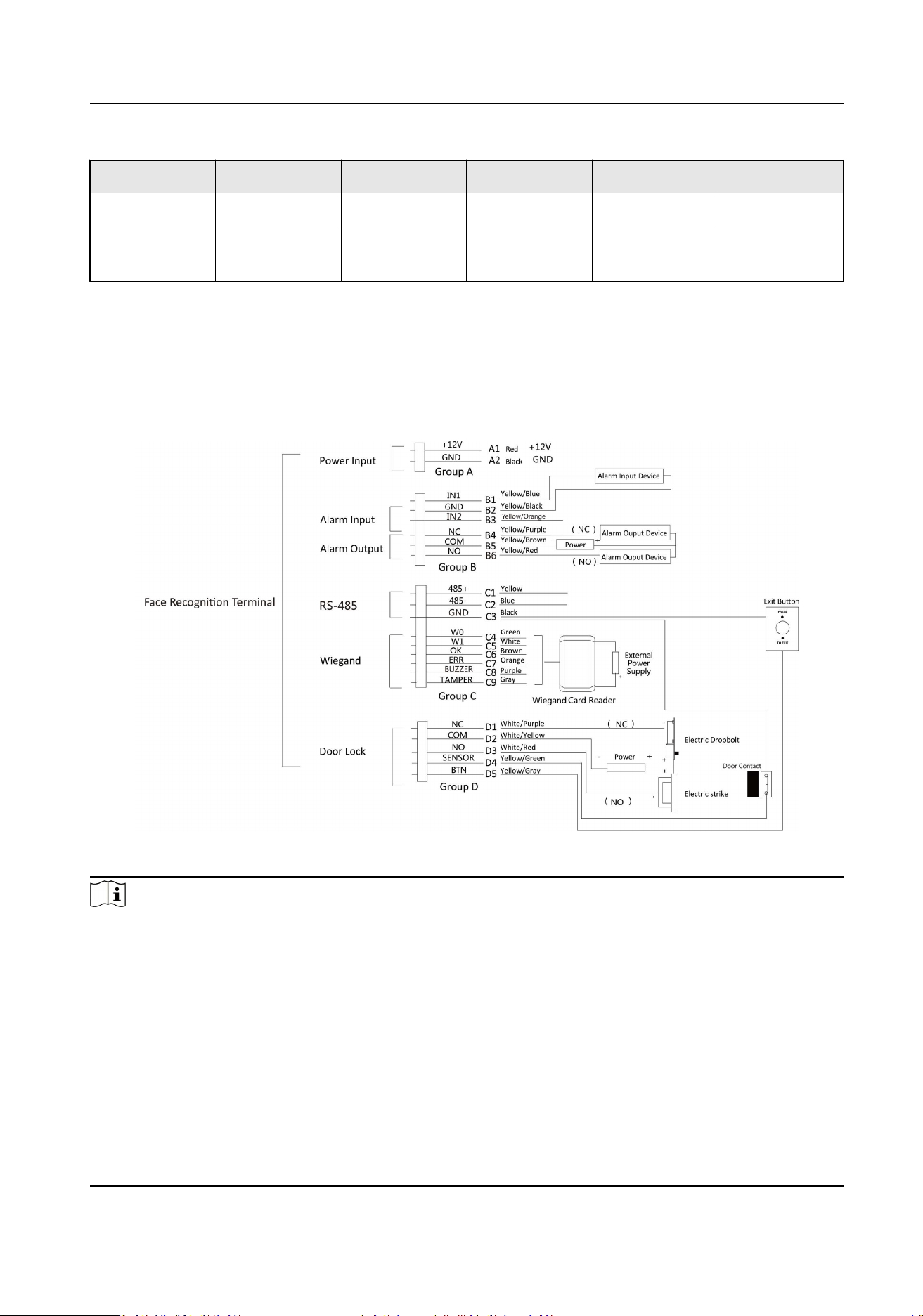
4.2 Wire Normal Device
You can connect the terminal with normal peripherals.
The wiring diagram without secure door control unit is as follows.
Figure 4-2 Device Wiring
Note
●
You should set the face recognion terminal's Wiegand direcon to "Input" to connect to a
Wiegand card reader. If connects to an access controller, you should set the Wiegand direcon to
"Output" to transmit authencaon informaon to the access controller.
●
For details about Wiegand direcon sengs, see Seng Wiegand Parameters in Communicaon
Sengs.
●
The power supply for the device should be 12 VDC/2 A. The suggested external power supply for
door lock is 12 V, 1 A. The suggested external power supply for the Wiegand card reader is 12 V,
1A.
DS-K1TA70 Series Face Recognion Terminal User Manual
16
●
The suggested power cable's diameter: 22 AWG. The suggested other cable's diameter: 26 AWG.
●
Do not wire the device to the electric supply directly.
Warning
The face recognion terminal shall adapt an external listed Class 2 power supply with surge
protected funcon.
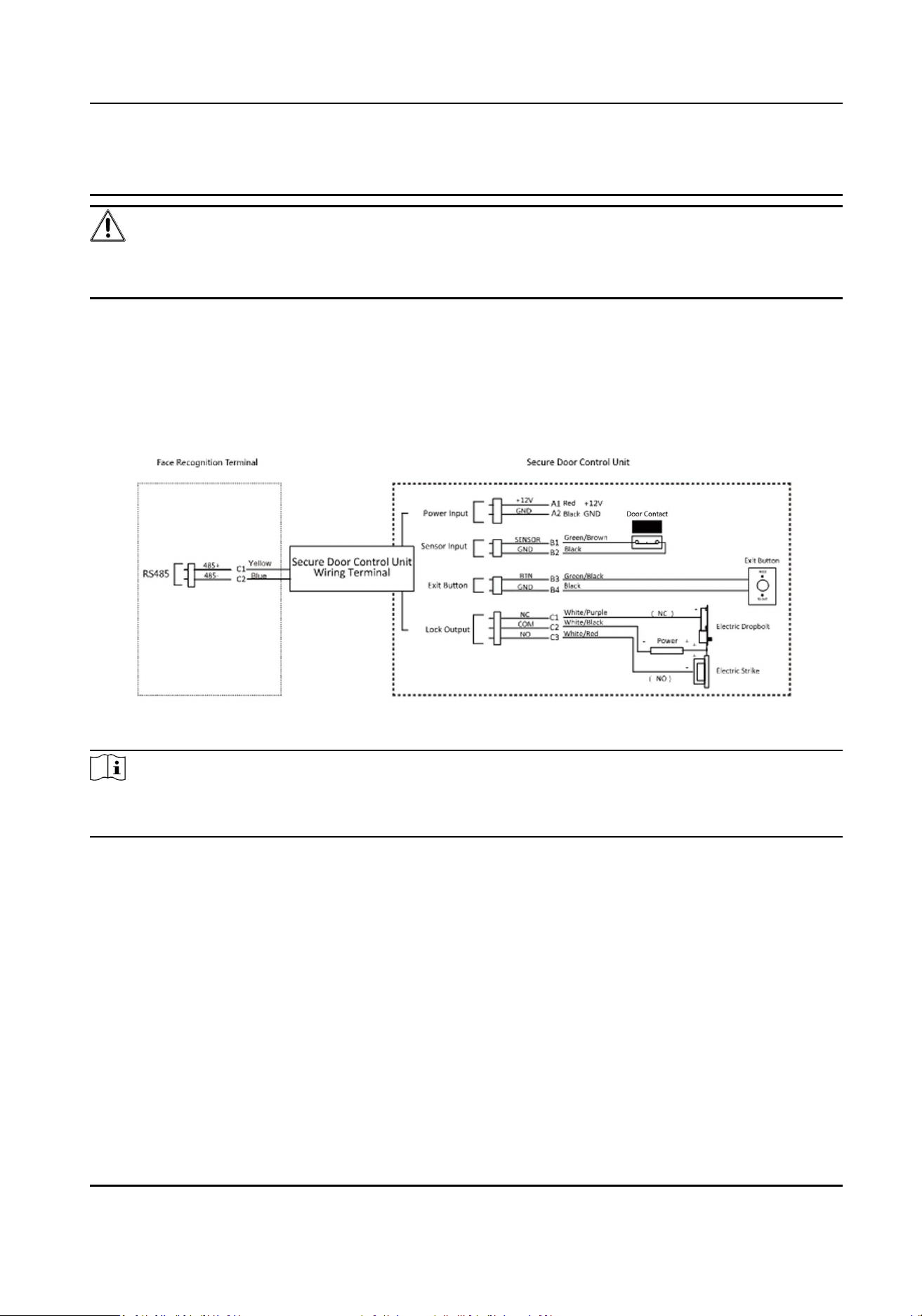
4.3 Wire Secure Door Control Unit
You can connect the terminal with the secure door control unit.
The wiring diagram is as follows.
Figure 4-3 Secure Door Control Unit Wiring
Note
The secure door control unit should connect to an external power supply separately. The suggested
external power supply is 12V, 0.5A.
4.4 Wire Fire Module
4.4.1 Wiring Diagram of Door Open When Powering O
Lock Type: Anode Lock, Magnec Lock, and Electric Bolt (NO)
Security Type: Door Open When Powering O
Scenario: Installed in Fire Engine Access
DS-K1TA70 Series Face Recognion Terminal User Manual
17
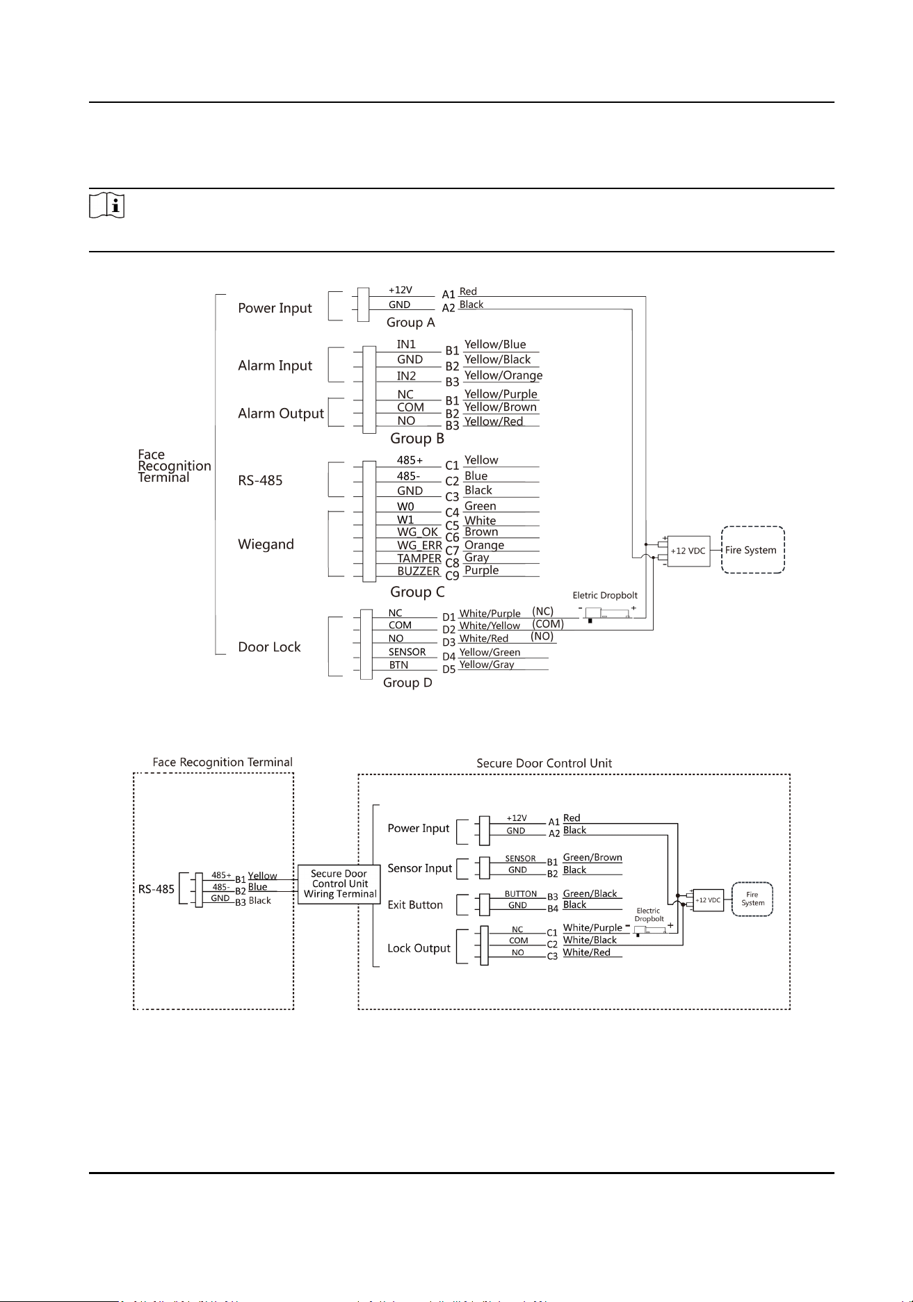
Type 1
Note
The re system controls the power supply of the access control system.
Figure 4-4 Wire Device
Figure 4-5 Wire Secure Door Control Unit
DS-K1TA70 Series Face Recognion Terminal User Manual
18
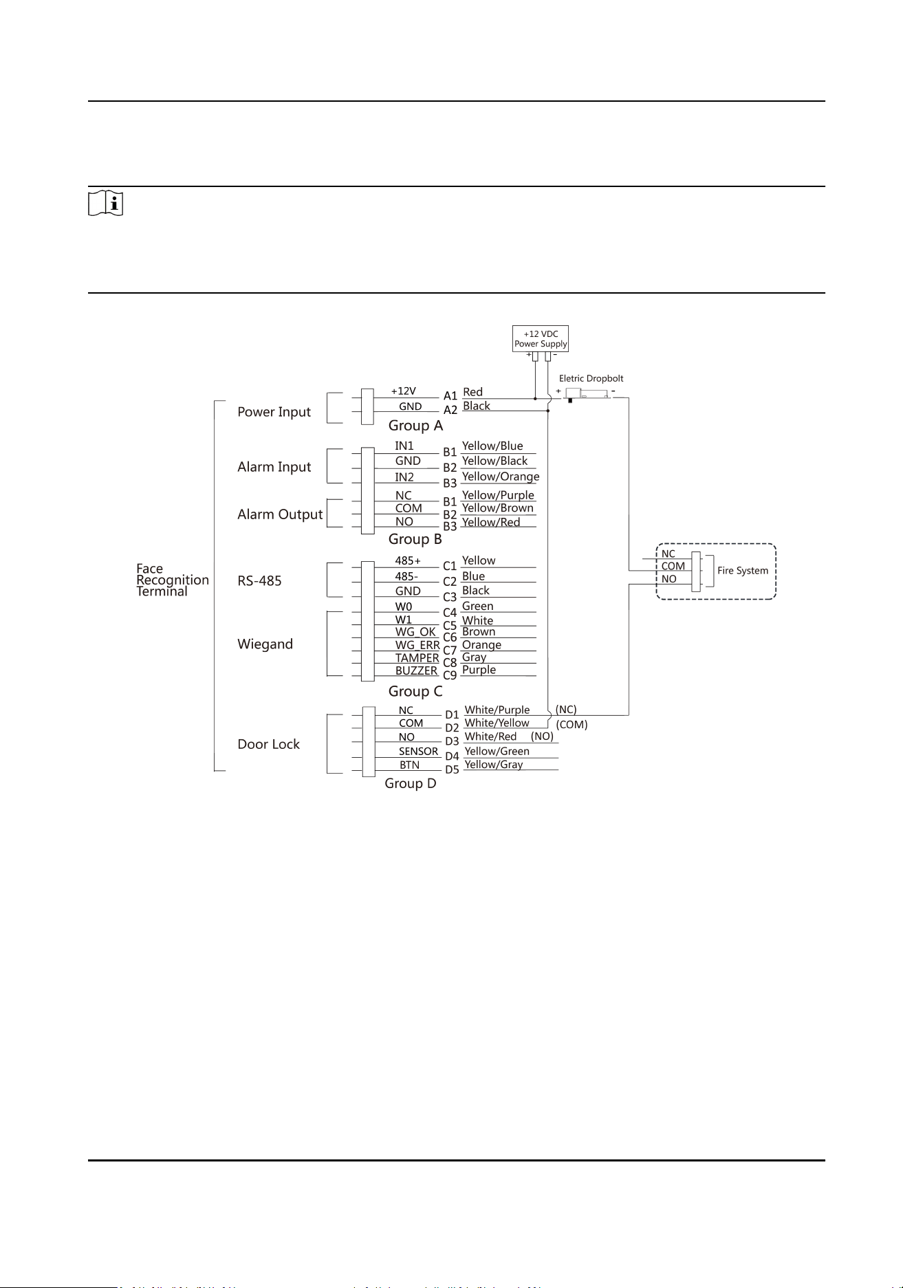
Type 2
Note
The re system (NO and COM, normally open when powering o) is connected with the lock and
the power supply in series. When an re alarm is triggered, the door remains open. In normal
mes, NO and COM are closed.
Figure 4-6 Wiring Device
DS-K1TA70 Series Face Recognion Terminal User Manual
19
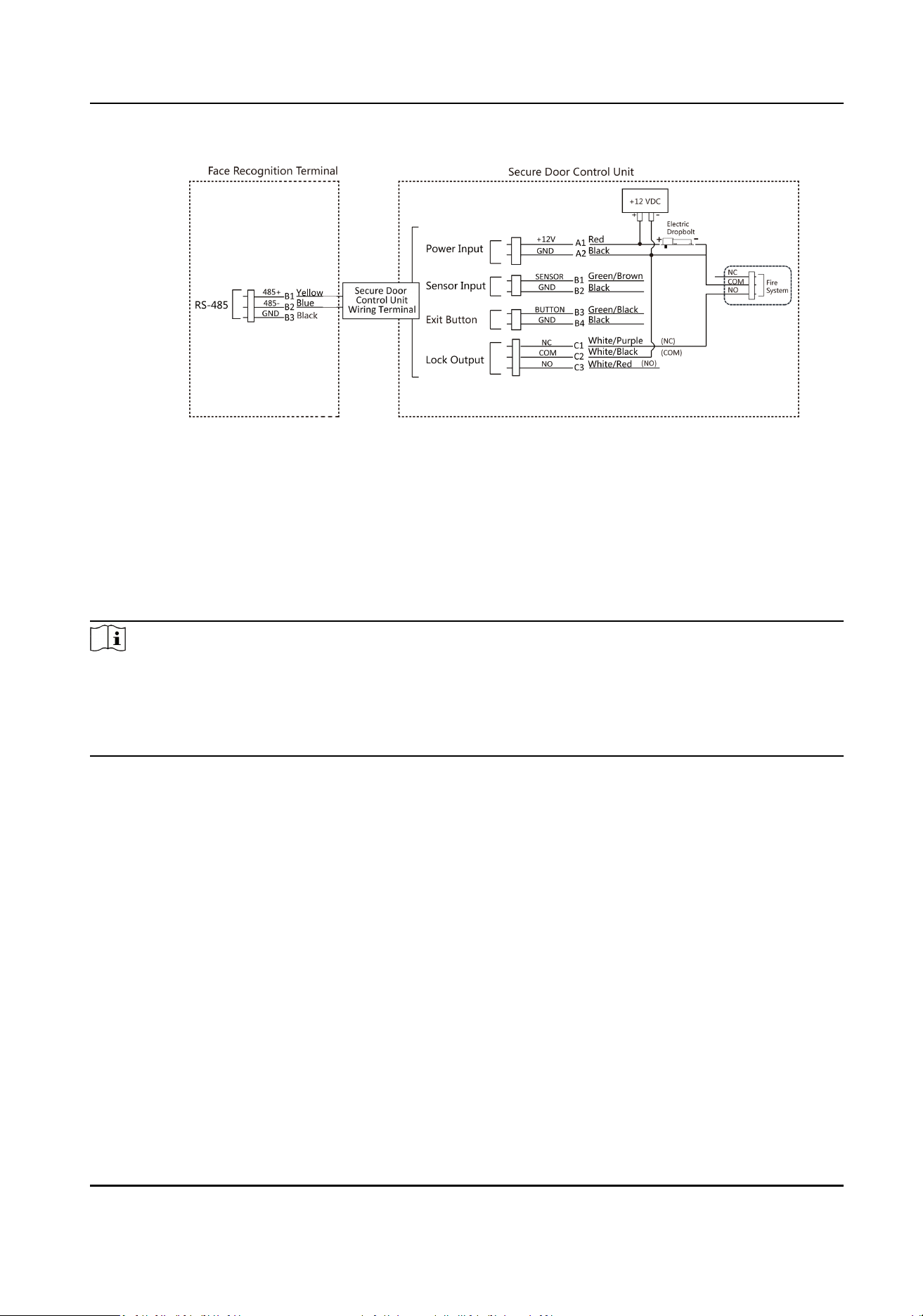
Figure 4-7 Wiring Secure Door Control Unit
4.4.2 Wiring Diagram of Door Locked When Powering O
Lock Type: Cathode Lock, Electric Lock, and Electric Bolt (NC)
Security Type: Door Locked When Powering O
Scenario: Installed in Entrance/Exit with Fire Linkage
Note
●
The Uninterpretable Power Supply (UPS) is required.
●
The re system (NC and COM, normally closed when powering o) is connected with the lock
and the power supply in series. When an re alarm is triggered, the door remains open. In
normal mes, NC and COM are open.
DS-K1TA70 Series Face Recognion Terminal User Manual
20
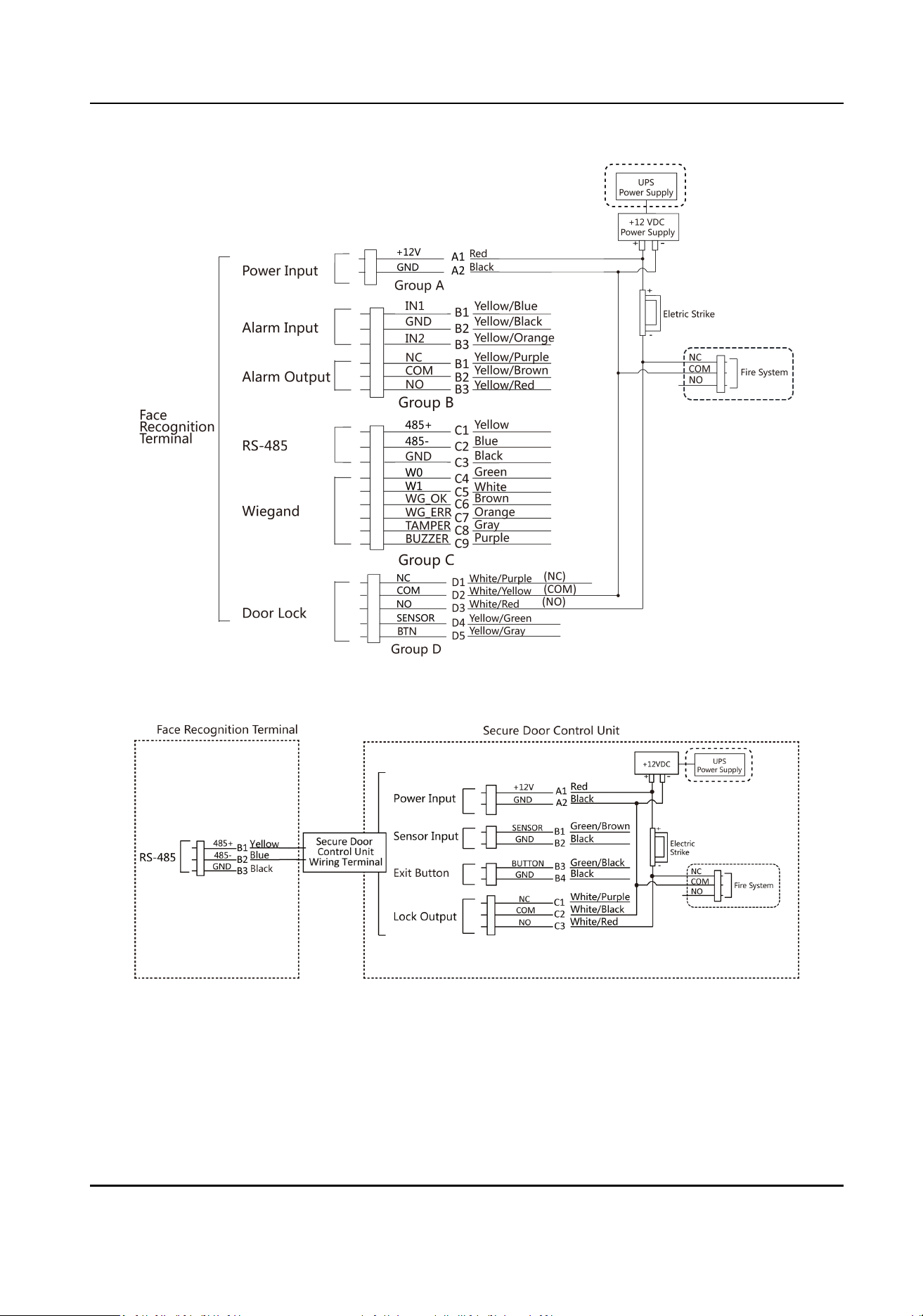
Figure 4-8 Device Wiring
Figure 4-9 Wiring Diagram
DS-K1TA70 Series Face Recognion Terminal User Manual
21

Chapter 5 Acvaon
You should acvate the device before the rst login. Aer powering on the device, the system will
switch to Device Acvaon page.
Acvaon via the device, SADP tool and the client soware are supported.
The default values of the device are as follows:
●
The default IP address: 192.0.0.64
●
The default port No.: 8000
●
The default user name: admin
5.1 Acvate via Device
If the device is not acvated, you can acvate the device aer it is powered on.
On the Acvate Device page, create a password and conrm the password. Tap Acvate and the
device will acvated.
DS-K1TA70 Series Face Recognion Terminal User Manual
22
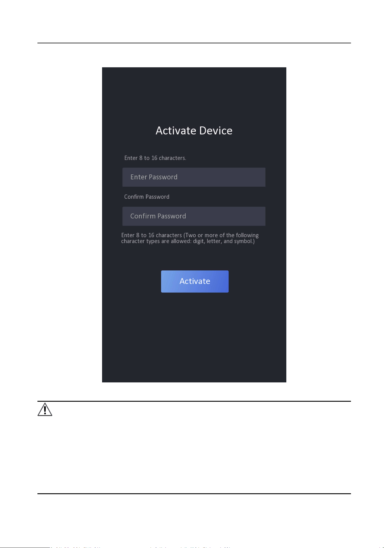
Figure 5-1 Acvaon Page
Cauon
The password strength of the device can be automacally checked. We highly recommend you
change the password of your own choosing (using a minimum of 8 characters, including at least
three kinds of following categories: upper case leers, lower case leers, numbers, and special
DS-K1TA70 Series Face Recognion Terminal User Manual
23
characters) in order to increase the security of your product. And we recommend you change your
password regularly, especially in the high security system, changing the password monthly or
weekly can beer protect your product.
Proper conguraon of all passwords and other security sengs is the responsibility of the
installer and/or end-user.
Note
Characters containing admin and nimda are not supported to be set as acvaon password.
●
Aer acvaon, you should select a language according to your actual needs.
●
Aer acvaon, you should select an applicaon mode. For details, see Set Applicaon Mode .
●
Aer acvaon, if you need to add the device to the client soware or other plaorms, you
should edit the device IP address. For details, see Set Network Parameters .
●
Aer acvaon, if you need to operate the device remotely via APP, you should scan the QR
code to link to the APP. For details, see .
●
Aer acvaon, if you need to add administrator to manage the device parameters, you should
set administrator. For details, see
Add Administrator .
5.2 Acvate via SADP
SADP is a tool to detect, acvate and modify the IP address of the device over the LAN.
Before You Start
●
Get the SADP soware from the supplied disk or the ocial website
hp://
www.hikvision.com/en/ , and install the SADP according to the prompts.
●
The device and the PC that runs the SADP tool should be within the same subnet.
The following steps show how to acvate a device and modify its IP address. For batch acvaon
and IP addresses modicaon, refer to User Manual of SADP for details.
Steps
1.
Run the SADP soware and search the online devices.
2.
Find and select your device in online device list.
3.
Input new password (admin password) and conrm the password.
Cauon
STRONG PASSWORD RECOMMENDED-We highly recommend you create a strong password of
your own choosing (using a minimum of 8 characters, including upper case leers, lower case
leers, numbers, and special characters) in order to increase the security of your product. And
we recommend you reset your password regularly, especially in the high security system,
reseng the password monthly or weekly can beer protect your product.
DS-K1TA70 Series Face Recognion Terminal User Manual
24
Note
Characters containing admin and nimda are not supported to be set as acvaon password.
4.
Click Acvate to start acvaon.
Status of the device becomes Acve aer successful acvaon.
5.
Modify IP address of the device.
1) Select the device.
2) Change the device IP address to the same subnet as your computer by either modifying the IP
address manually or checking Enable DHCP.
3) Input the admin password and click Modify to acvate your IP address modicaon.
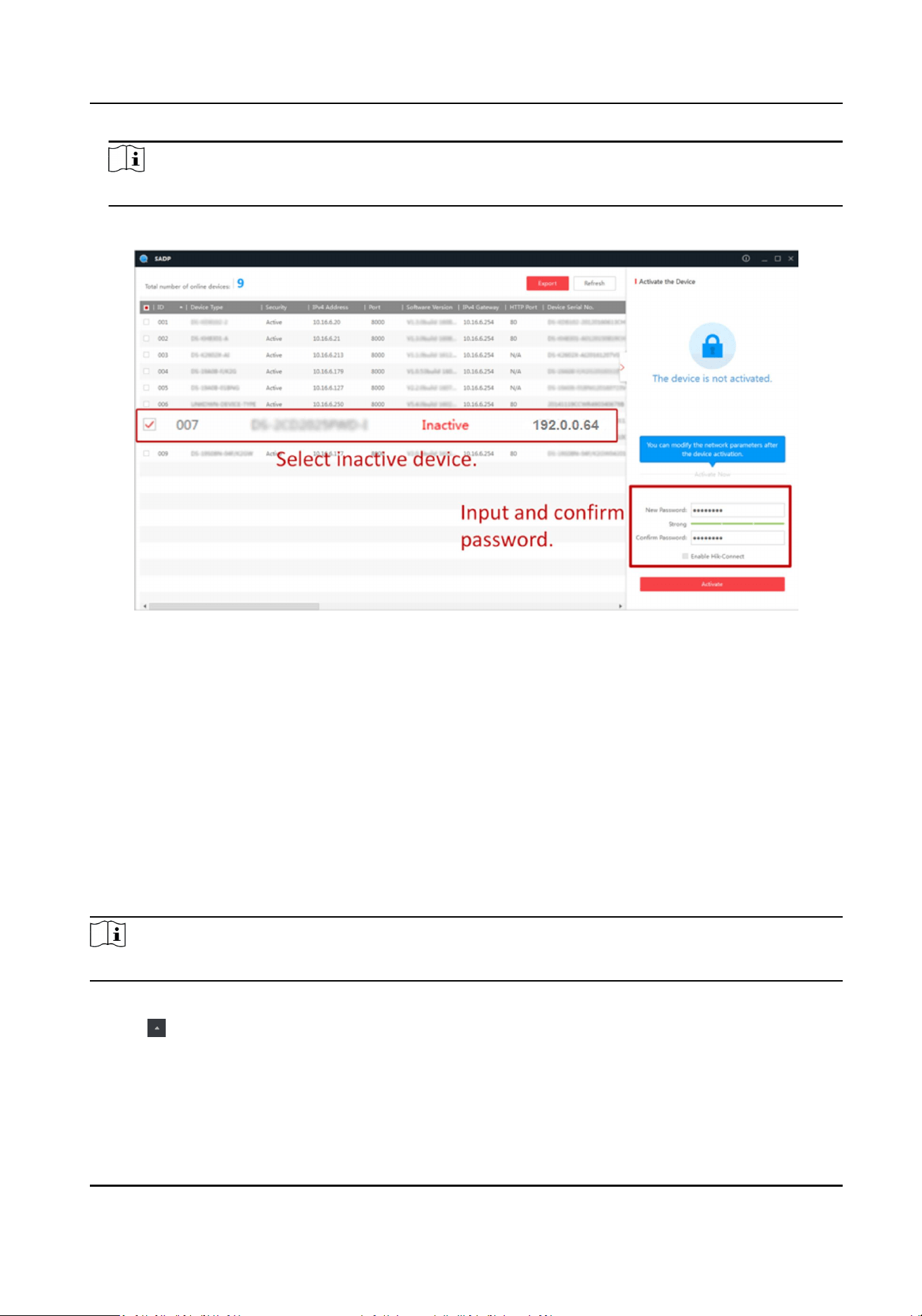
5.3 Acvate Device via Client Soware
For some devices, you are required to create the password to acvate them before they can be
added to the soware and work properly.
Steps
Note
This funcon should be supported by the device.
1.
Enter the Device Management page.
2.
Click on the right of Device Management and select Device.
3.
Click Online Device to show the online device area.
The searched online devices are displayed in the list.
4.
Check the device status (shown on Security Level column) and select an inacve device.
DS-K1TA70 Series Face Recognion Terminal User Manual
25
5.
Click Acvate to open the Acvaon dialog.
6.
Create a password in the password eld, and conrm the password.
Cauon
The password strength of the device can be automacally checked. We highly recommend you
change the password of your own choosing (using a minimum of 8 characters, including at least
three kinds of following categories: upper case leers, lower case leers, numbers, and special
characters) in order to increase the security of your product. And we recommend you change
your password regularly, especially in the high security system, changing the password monthly
or weekly can beer protect your product.
Proper conguraon of all passwords and other security sengs is the responsibility of the
installer and/or end-user.
Note
Characters containing admin and nimda are not supported to be set as acvaon password.
7.
Click OK to acvate the device.
5.4 Acvate via Web Browser
You can acvate the device via the web browser.
Steps
1.
Enter the device default IP address (192.0.0.64) in the address bar of the web browser, and press
Enter.
Note
Make sure the device IP address and the computer's should be in the same IP segment.
2.
Create a new password (admin password) and conrm the password.
Cauon
STRONG PASSWORD RECOMMENDED-We highly recommend you create a strong password of
your own choosing (using a minimum of 8 characters, including upper case leers, lower case
leers, numbers, and special characters) in order to increase the security of your product. And
we recommend you reset your password regularly, especially in the high security system,
reseng the password monthly or weekly can beer protect your product.
Note
Characters containing admin and nimda are not supported to be set as acvaon password.
3.
Click Acvate.
4.
Edit the device IP address. You can edit the IP address via the SADP tool, the device, and the
client soware.
DS-K1TA70 Series Face Recognion Terminal User Manual
26

Chapter 6 Quick Operaon
6.1 Select Language
You can select a language for the device system.
Aer the device acvaon, you can select a language for the device system.
DS-K1TA70 Series Face Recognion Terminal User Manual
27

Figure 6-1 Select System Language
By default, the system language is English.
Note
Aer you change the system language, the device will reboot automacally.
DS-K1TA70 Series Face Recognion Terminal User Manual
28
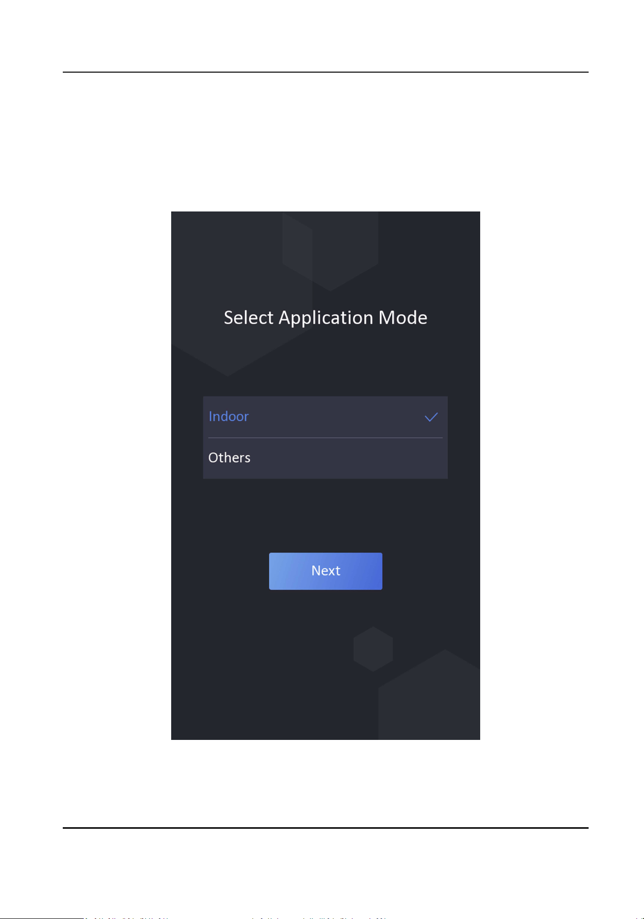
6.2 Set Applicaon Mode
Aer acvang the device, you should select an applicaon mode for beer device applicaon.
Steps
1.
On the Welcome page, select Indoor or Others from the drop-down list.
Figure 6-2 Welcome Page
2.
Tap OK to save.
DS-K1TA70 Series Face Recognion Terminal User Manual
29
Note
●
You can also change the sengs in System Sengs.
●
If you install the device indoors near the window or the face recognion funcon is not
working well, select Others.
●
If you do not congure the applicaon mode and tap Next, the system will select Indoor by
default.
●
If you acvate the device via other tools remotely, the system will select Indoor as the
applicaon mode by default.
6.3 Set Network Parameters
Aer acvaon and select applicaon mode, you can set the network for the device
Steps
1.
Set the wired network parameters.
-
If enable DHCP, the system will assign the IP address and other parameters automacally.
-
If disable DHCP, you should set the IP address, the subnet mask, and the gateway.
Note
Make sure the device has connected to a network.
2.
Tap Next.
3.
Oponal: Tap Skip to skip network sengs.
6.4 Set Administrator
Aer device acvaon, you can add an administrator to manage the device parameters.
Before You Start
Acvate the device and select an applicaon mode.
Steps
1.
Oponal: Tap Skip to skip adding administrator if required.
2.
Enter the administrator's name (oponal) and tap Next.
DS-K1TA70 Series Face Recognion Terminal User Manual
30
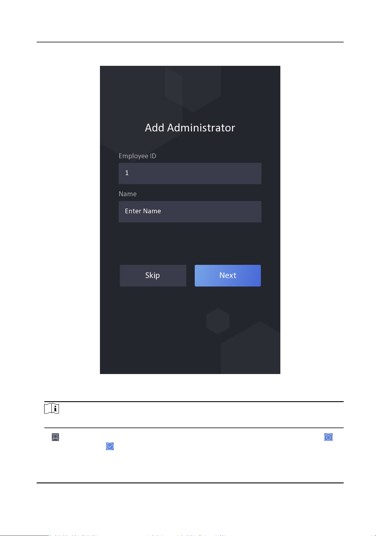
Figure 6-4 Add Administrator Page
3.
Select a credenal to add.
Note
Up to one credenal should be added.
-
: Face forward at the camera. Make sure the face is in the face recognion area. Click to
capture and click to conrm.
DS-K1TA70 Series Face Recognion Terminal User Manual
31
-
: Enter the card No. or present card on the card presenng area. Click OK.
4.
Click OK.
You will enter the authencaon page.
Status Icon Descripon
/
Device is armed/not armed.
/
Hik-Connect is enabled/disabled.
/ /
The device wired network is connected/not connected/connecng failed.
Shortcut Keys Descripon
Note
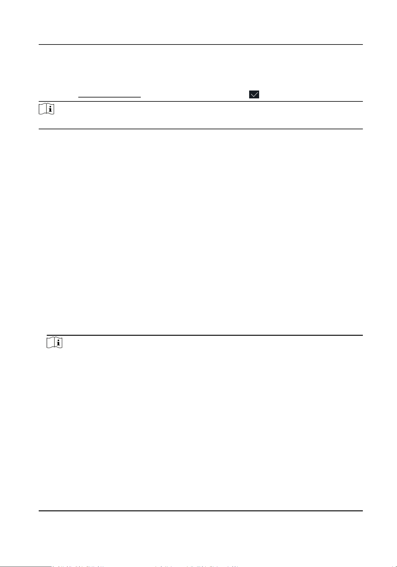
You can congure those shortcut keys displayed on the screen. For details, see Basic Sengs .
Scan QR code to authencate.
Note
The QR code can be obtained from the visitor terminal.
●
Enter the device room No. and tap OK to call.
●
Tap
to call the center.
Note
The device should be added to the center, or the calling operaon will be failed.
Enter password to authencate.
DS-K1TA70 Series Face Recognion Terminal User Manual
32

Chapter 7 Basic Operaon
7.1 Login
Login the device to set the device basic parameters.
7.1.1 Login by Administrator
If you have added an administrator for the device, only the administrator can login the device for
device operaon.
Steps
1.
Long tap on the inial page for 3 s and slide to the le/right by following the gesture to enter
the admin login page.
DS-K1TA70 Series Face Recognion Terminal User Manual
33
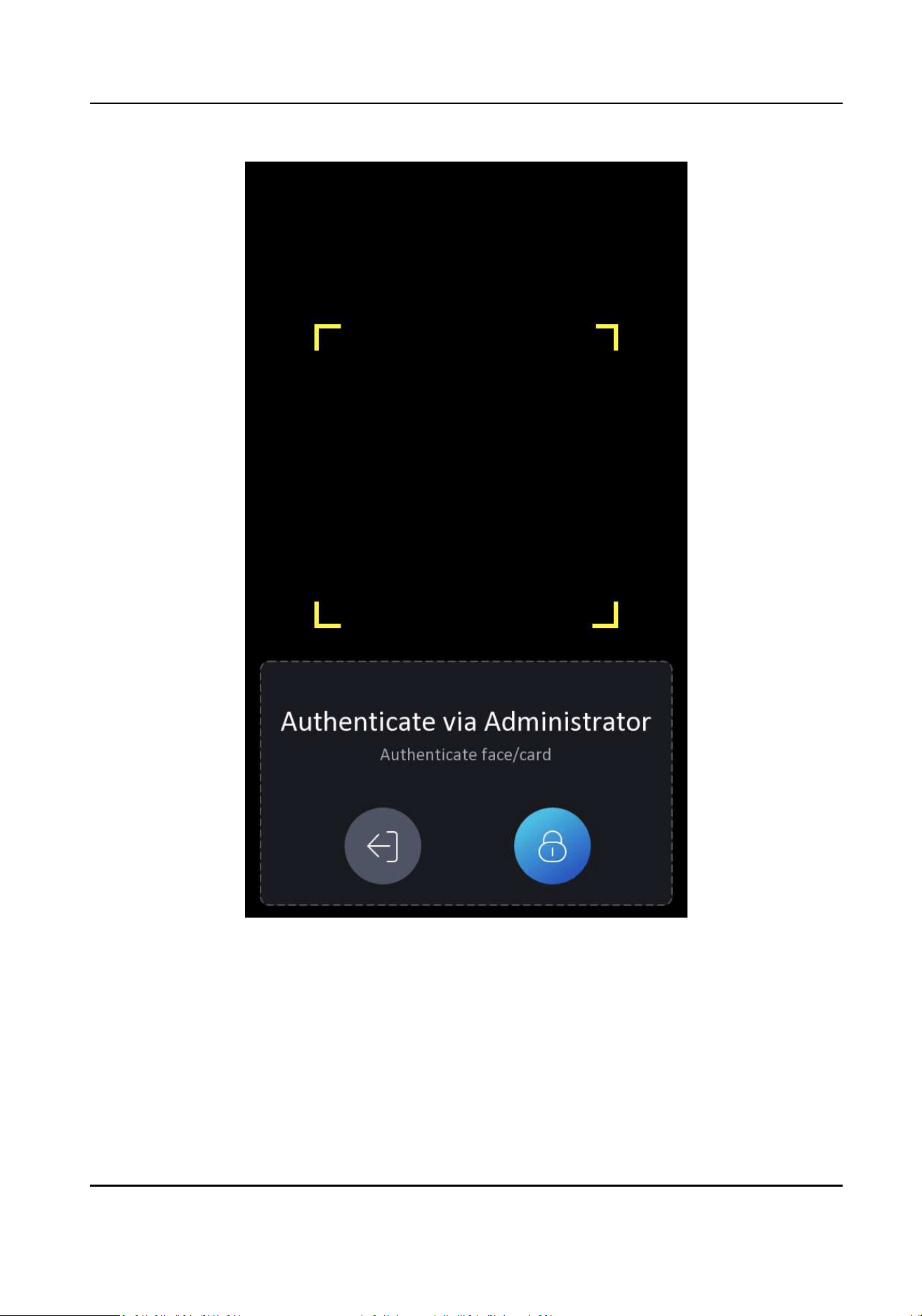
Figure 7-1 Admin Login
2.
Authencate the administrator's face or card to enter the home page.
DS-K1TA70 Series Face Recognion Terminal User Manual
34
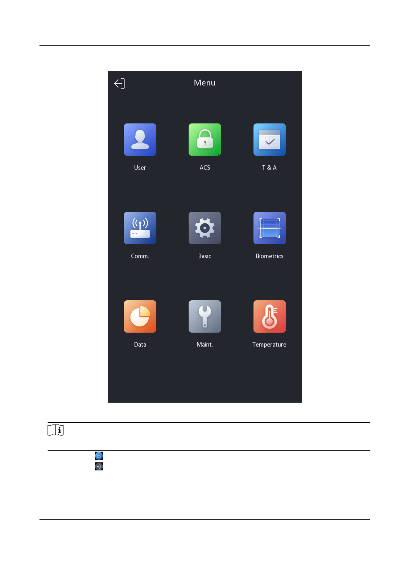
Figure 7-2 Home Page
Note
The device will be locked for 30 minutes aer 5 failed aempts.
3.
Oponal: Tap and you can enter the device acvaon password for login.
4.
Oponal: Tap and you can exit the admin login page.
DS-K1TA70 Series Face Recognion Terminal User Manual
35
7.1.2 Login by Acvaon Password
You should login the system before other device operaons. If you do not congure an
administrator, you should follow the instrucons below to login.
Steps
1.
Long tap on the inial page for 3 s and slide to the le/right by following the gesture to enter
password entering page.
2.
Tap the Password eld and enter the device acvaon password.
3.
Tap OK to enter the home page.
Note
The device will be locked for 30 minutes aer 5 failed password aempts.
DS-K1TA70 Series Face Recognion Terminal User Manual
36
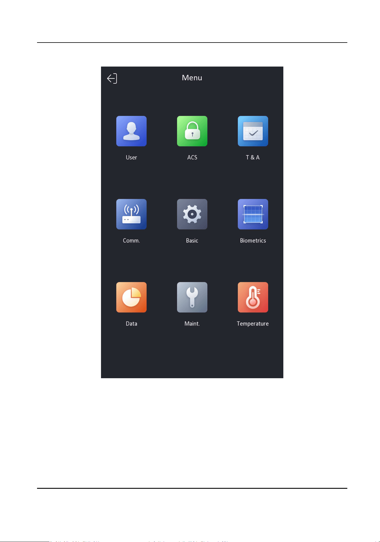
Figure 7-3 Home Page
7.2 Communicaon Sengs
You can set the network parameters, the RS-485 parameters, and the Wiegand parameters on the
communicaon sengs page.
DS-K1TA70 Series Face Recognion Terminal User Manual
37

7.2.1 Set Wired Network Parameters
You can set the device wired network parameters, including the IP address, the subnet mask, the
gateway, and DNS parameters.
Steps
1.
Tap Comm. (Communicaon Sengs) on the Home page to enter the Communicaon Sengs
page.
2.
On the Communicaon Sengs page, tap Wired Network.
Figure 7-4 Wired Network Sengs
3.
Set IP Address, Subnet Mask, and Gateway.
-
Enable DHCP, and the system will assign IP address, subnet mask, and gateway automacally.
DS-K1TA70 Series Face Recognion Terminal User Manual
38
-
Disable DHCP, and you should set the IP address, subnet mask, and gateway manually.
Note
The device's IP address and the computer IP address should be in the same IP segment.
4.
Set the DNS parameters. You can enable Auto Obtain DNS, set the preferred DNS server and the
alternate DNS server.
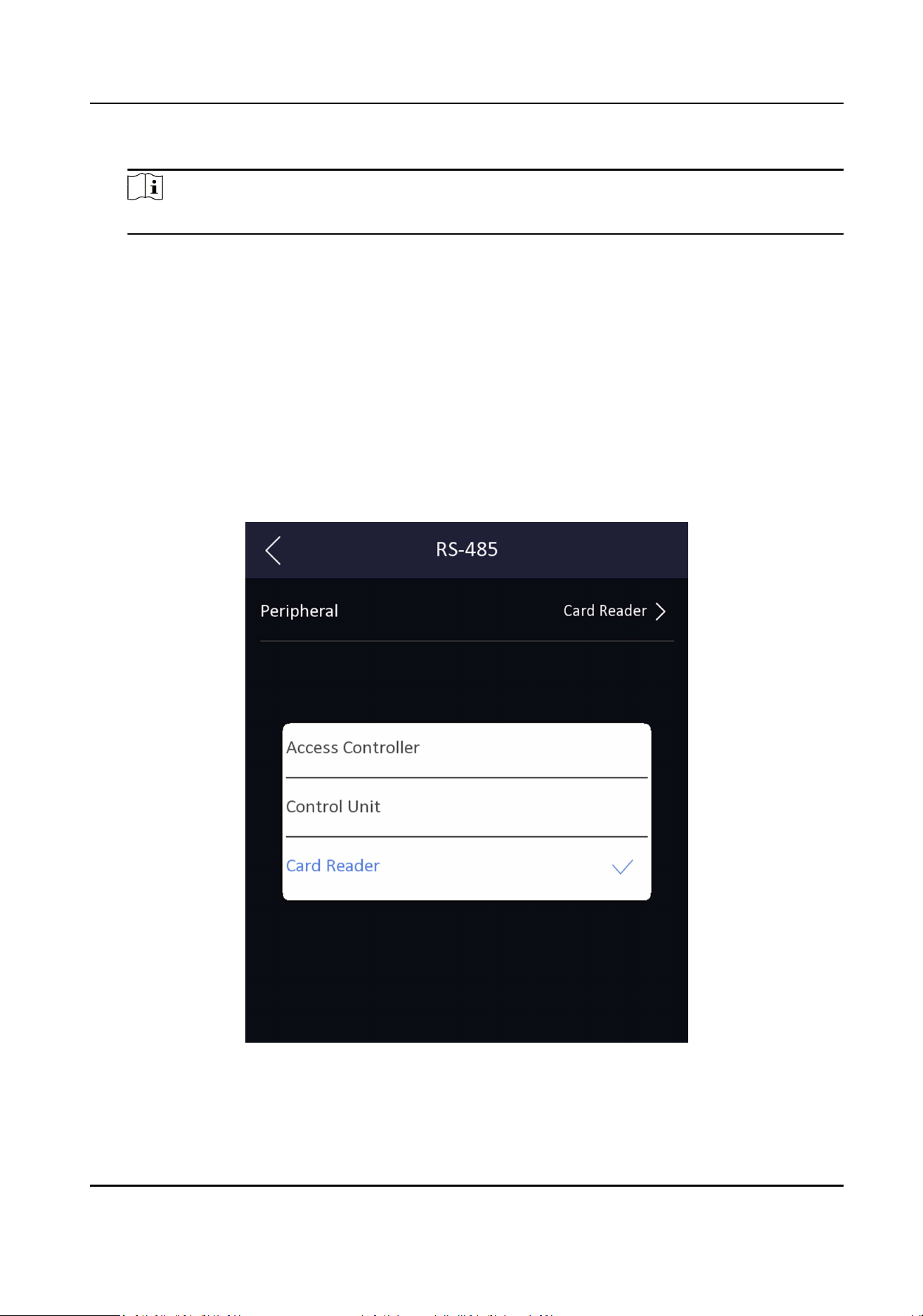
7.2.2 Set RS-485 Parameters
The face recognion terminal can connect external access controller, secure door control unit or
card reader via the RS-485 terminal.
Steps
1.
Tap Comm. (Communicaon Sengs) on the Home page to enter the Communicaon Sengs
page.
2.
On the Communicaon Sengs page, tap RS-485 to enter the RS-485 tab.
Figure 7-5 Set RS-485 Parameters
3.
Select an peripheral type according to your actual needs.
DS-K1TA70 Series Face Recognion Terminal User Manual
39
Note
If you select Access Controller: If connect the device to a terminal via the RS-485 interface, set
the RS-485 address as 2. If you connect the device to a controller, set the RS-485 address
according to the door No.
4.
Tap the back icon at the upper le corner and you should reboot the device if you change the
parameters.
7.2.3 Set Wiegand Parameters
You can set the Wiegand transmission direcon.
Steps
1.
Tap Comm. (Communicaon Sengs) on the Home page to enter the Communicaon Sengs
page.
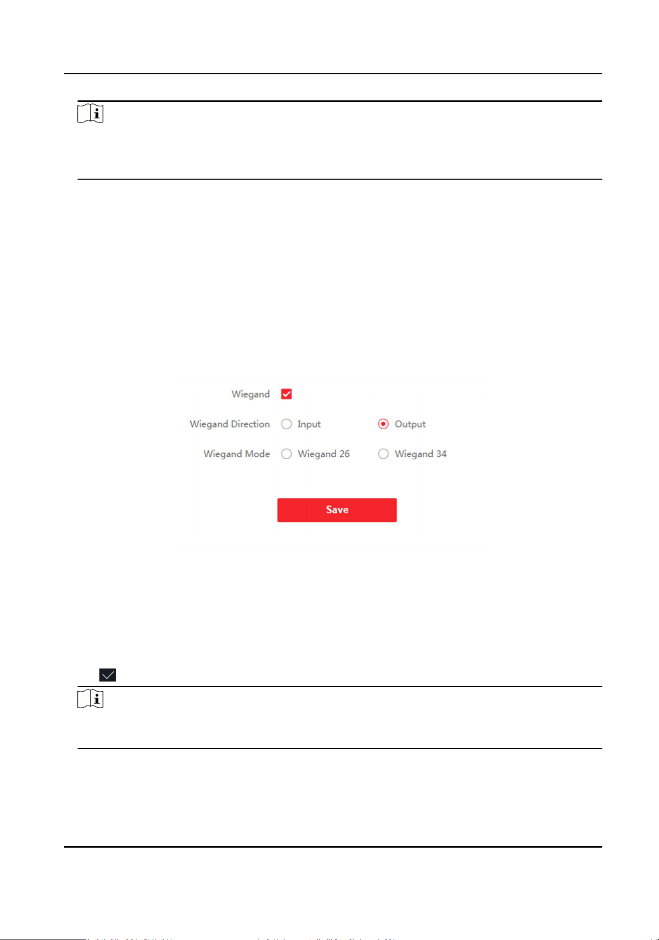
2.
On the Communicaon Sengs page, tap Wiegand to enter the Wiegand tab.
Figure 7-6 Wiegand Sengs
3.
Enable the Wiegand funcon.
4.
Select a transmission direcon.
●
Output: A face recognion terminal can connect an external access controller. And the two
devices will transmit the card No. via Wiegand 26 or Wiegand 34.
●
Input: A face recognion terminal can connect a Wiegand card reader.
5.
Tap to save the network parameters.
Note
If you change the external device, and aer you save the device parameters, the device will
reboot automacally.
DS-K1TA70 Series Face Recognion Terminal User Manual
40
7.3 User Management
On the user management interface, you can add, edit, delete and search the user.
7.3.1 Add Administrator
The administrator can login the device backend and congure the device parameters.
Steps
1.
Long tap on the inial page and log in the backend.
2.
Tap User → + to enter the Add User page.
3.
Edit the employee ID.
Note
●
The employee ID should be less than 32 characters. And it can be a combinaon of lower
leers, upper leers, and numbers.
●
The employee ID should not be duplicated.
4.
Tap the Name eld and input the user name on the so keyboard.
Note
●
Numbers, upper case leers, lower case leers, and special characters are allowed in the user
name.
●
Up to 32 characters are allowed in the user name.
5.
Oponal: Add a face picture, or cards for the administrator.
Note
●
For details about adding a face picture, see Add Face Picture .
●
For details about adding a card, see Add Card .
6.
Oponal: Set the administrator's authencaon type.
Note
For details about seng the authencaon type, see Set Authencaon Mode .
7.
Enable the Administrator Permission funcon.
Enable Administrator Permission
The user is the administrator. Except for the normal aendance funcon, the user can also
enter the Home page to operate aer authencang the permission.
8.
Tap
to save the sengs.
DS-K1TA70 Series Face Recognion Terminal User Manual
41
7.3.2 Add Face Picture
Add user's face picture to the device. And the user can use the face picture to authencate.
Steps
1.
Long tap on the inial page for 3 s and slide to the le/right by following the gesture and log in
the backend.
2.
Tap User → + to enter the Add User page.
3.
Edit the employee ID.
Note
●
The employee ID should be less than 32 characters. And it can be a combinaon of lower
leers, upper leers, and numbers.
●
The employee ID should not be duplicated.
4.
Tap the Name eld and input the user name on the so keyboard.
Note
●
Numbers, upper case leers, lower case leers, and special characters are allowed in the user
name.
●
The suggested user name should be within 32 characters.
5.
Tap the Face Picture eld to enter the face picture adding page.
DS-K1TA70 Series Face Recognion Terminal User Manual
42
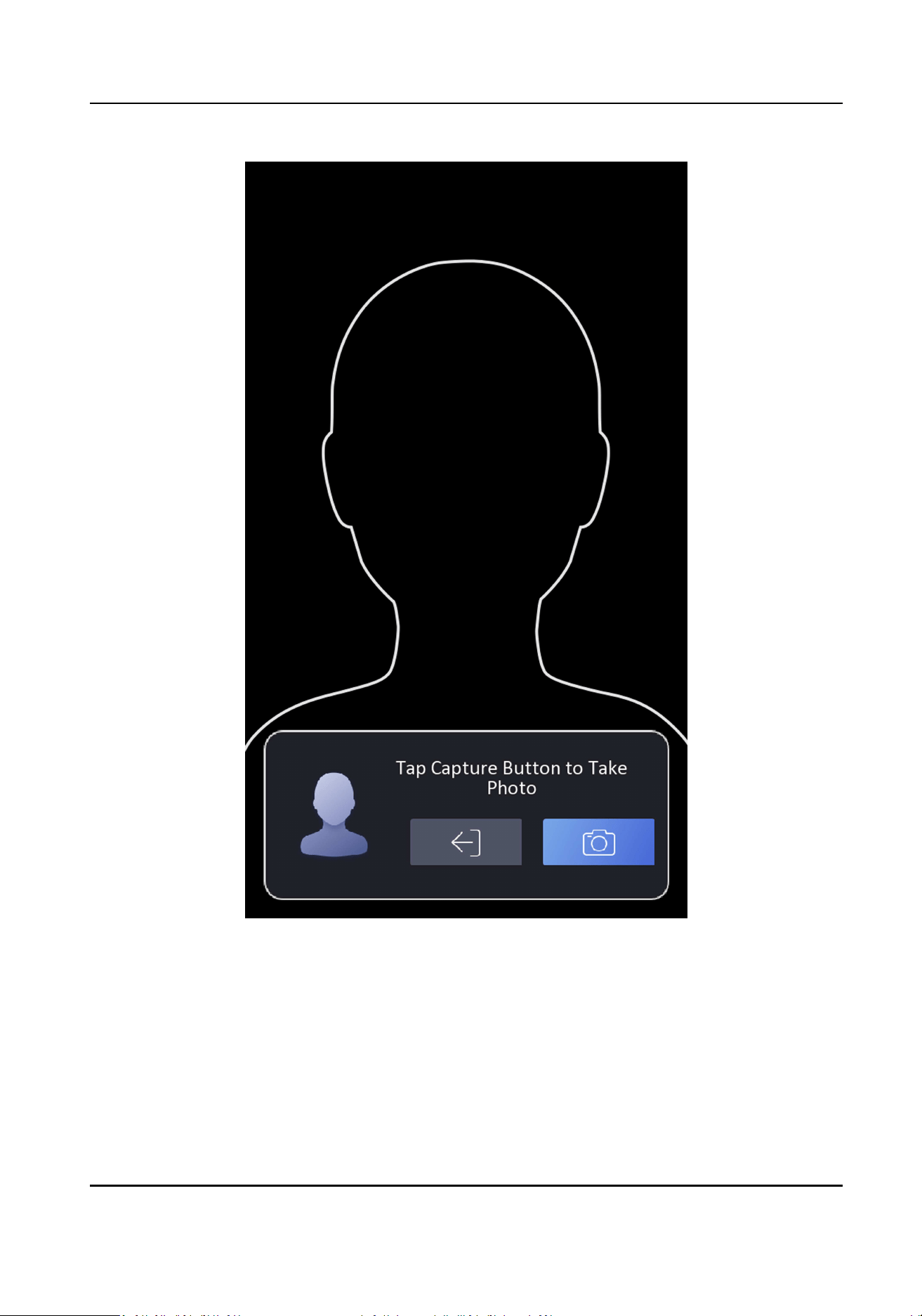
Figure 7-7 Add Face Picture
6.
Look at the camera.
DS-K1TA70 Series Face Recognion Terminal User Manual
43
Note
●
Make sure your face picture is in the face picture outline when adding the face picture.
●
Make sure the captured face picture is in good quality and is accurate.
●
For details about the instrucons of adding face pictures, see Tips When Collecng/
Comparing Face Picture .
Aer completely adding the face picture, a captured face picture will be displayed at the upper
right corner of the page.
7.
Tap Save to save the face picture.
8.
Oponal: Tap Try Again and adjust your face posion to add the face picture again.
9.
Set the user role.
Administrator
The user is the administrator. Except for the normal aendance funcon, the user can also
enter the Home page to operate aer authencang the permission.
Normal User
The User is the normal user. The user can only authencate or take aendance on the inial
page.
10.
Tap to save the sengs.
7.3.3 Add Card
Add a card for the user and the user can authencate via the added card.
Steps
1.
Long tap on the inial page for 3 s and slide to the le/right by following the gesture and log in
the backend.
2.
Tap User → + to enter the Add User page.
3.
Connect an external card reader according to the wiring diagram.
4.
Tap the Employee ID. eld and edit the employee ID.
Note
●
The employee ID should be less than 32 characters. And it can be a combinaon of lower
leers, upper leers, and numbers.
●
The employee ID should not be duplicated.
5.
Tap the Name eld and input the user name on the so keyboard.
Note
●
Numbers, upper case leers, lower case leers, and special characters are allowed in the user
name.
●
The suggested user name should be within 32 characters.
6.
Tap the Card eld and tap +.
DS-K1TA70 Series Face Recognion Terminal User Manual
44
7.
Congure the card No.
-
Enter the card No. manually.
-
Present the card over the card presenng area to get the card No.
Note
●
The card No. cannot be empty.
●
Up to 20 characters are allowed in the card No.
●
The card No. cannot be duplicated.
8.
Congure the card type.
9.
Set the user role.
Administrator
The user is the administrator. Except for the normal aendance funcon, the user can also
enter the Home page to operate aer authencang the permission.
Normal User
The User is the normal user. The user can only authencate or take aendance on the inial
page.
10.
Tap to save the sengs.
7.3.4 View Password
Add a password for the user and the user can authencate via the password.
Steps
1.
Long tap on the inial page for 3 s and slide to the le/right by following the gesture and log in
the backend.
2.
Tap User → + to enter the Add User page.
3.
Tap the Employee ID. eld and edit the employee ID.
Note
●
The employee ID should be less than 32 characters. And it can be a combinaon of lower
leers, upper leers, and numbers.
●
The employee ID should not be duplicated.
4.
Tap the Name eld and input the user name on the so keyboard.
Note
●
Numbers, upper case leers, lower case leers, and special characters are allowed in the user
name.
●
The suggested user name should be within 32 characters.
5.
Tap the Password to view the password.
DS-K1TA70 Series Face Recognion Terminal User Manual
45

Note
The password cannot be edited. It can only be applied by the plaorm.
6.
Set the user role.
Administrator
The user is the administrator. Except for the normal aendance funcon, the user can also
enter the Home page to operate aer authencang the permission.
Normal User
The User is the normal user. The user can only authencate or take aendance on the inial
page.
7.
Tap to save the sengs.
7.3.5 Set Authencaon Mode
Aer adding the user's face picture, password, or other credenals, you should set the
authencaon mode and the user can authencate his/her identy via the congured
authencaon mode.
Steps
1.
Long tap on the inial page for 3 s and slide to the le/right by following the gesture and log in
the backend.
2.
Tap User → Add User/Edit User → Authencaon Mode .
3.
Select Device or Custom as the authencaon mode.
Device
If you want to select device mode, you should set the terminal authencaon mode in Access
Control Sengs page rst. For details see Seng Access Control Parameters.
Custom
You can combine dierent authencaon modes together according to your actual needs.
4.
Tap to save the sengs.
7.3.6 Search and Edit User
Aer adding the user, you can search the user and edit it.
Search User
On the User Management page, Tap the search area to enter the Search User page. Tap Card on
the le of the page and select a search type from the drop-down list. Enter the employee ID, card
No., or the user name for search. Tap to search.
DS-K1TA70 Series Face Recognion Terminal User Manual
46
Edit User
On the User Management page, select a user from the user list to enter the Edit User page. Follow
the steps in User Management to edit the user parameters. Tap to save the sengs.
Note
The employee ID cannot be edited.
7.4 Data Management
You can delete data, import data, and export data.
7.4.1 Delete Data
Delete user data.
On the Home page, tap Data → Delete Data → User Data . All user data added in the device will be
deleted.
7.4.2 Import Data
Steps
1.
Plug a USB ash drive in the device.
2.
On the Home page, tap Data → Import Data .
3.
Tap User Data or Face Data.
4.
Enter the created password when you exported the data. If you do not create a password when
you exported the data, leave a blank in the input box and tap OK immediately.
Note
●
If you want to transfer all user informaon from one device (Device A) to another (Device B),
you should export the informaon from Device A to the USB ash drive and then import from
the USB ash drive to Device B. In this case, you should import the user data before imporng
the prole photo.
●
The supported USB ash drive format is FAT32.
●
The imported pictures should be saved in the folder (named enroll_pic) of the root directory
and the picture's name should be follow the rule below:
Card No._Name_Department_Employee ID_Gender.jpg
●
If the folder enroll_pic cannot save all imported pictures, you can create another folders,
named enroll_pic1, enroll_pic2, enroll_pic3, enroll_pic4, under the root directory.
DS-K1TA70 Series Face Recognion Terminal User Manual
47
●
The employee ID should be less than 32 characters. It can be a combinaon of lower leers,
upper leers, and numbers. It should not be duplicated, and should not start with 0.
●
Requirements of face picture should follow the rules below: It should be taken in full-face
view, directly facing the camera. Do not wear a hat or head covering when taking the face
picture. The format should be JPEG or JPG. The resoluon should be 640 × 480 pixel or more
than of 640 × 480 pixel. The picture size should be between 60 KB and 200 KB.
7.4.3 Export Data
Steps
1.
Plug a USB ash drive in the device.
2.
On the Home page, tap Data → Export Data .
3.
Tap Face Data, Event Data, User Data, or Access Control Parameters.
Note
The exported access control parameters are conguraon les of the device.
4.
Oponal: Create a password for exporng. When you import those data to another device, you
should enter the password.
Note
●
The supported USB ash drive format is DB.
●
The system supports the USB ash drive with the storage of 1G to 32G. Make sure the free
space of the USB ash drive is more than 512M.
●
The exported user data is a DB le, which cannot be edited.
7.5 Identy Authencaon
Aer network conguraon, system parameters conguraon and user conguraon, you can go
back to the inial page for identy authencaon. The system will authencate person according
to the congured authencaon mode.
You can authencate identy via 1:1 matching or 1:N matching.
1:N Matching
Compare the captured face picture with all face pictures stored in the device.
1: 1 Matching
Compare the captured face picture with all face pictures stored in the device.
7.5.1 Authencate via Single Credenal
Set the user authencaon type before authencaon. For details, see Set Authencaon Mode .
Authencate face, or card.
DS-K1TA70 Series Face Recognion Terminal User Manual
48
Face
Face forward at the camera and start authencaon via face.
Card
Present the card on the card presenng area and start authencaon via card.
Note
The card can be normal IC card, or encrypted card.
If authencaon completed, a prompt "Authencated" will pop up.
7.5.2 Authencate via Mulple Credenal
Before You Start
Set the user authencaon type before authencaon. For details, see Set Authencaon Mode .
Steps
1.
If the authencaon mode is Card and Face, Password and Face, Card and Password,
authencate any credenal according to the instrucons on the live view page.
Note
The card can be normal IC card, or encrypted card.
2.
Aer the previous credenal is authencated, connue authencate the other credenal.
Note
For detailed informaon about authencang face, see Tips When Collecng/Comparing Face
Picture.
If authencaon succeeded, the prompt "Authencated" will pop up.
7.6 Basic Sengs
You can set the shortcut key, voice, me, language, supplement light, community No., building No.,
Unit No., beauty, and adversement.
Long tap on the inial page for 3 s and slide to the le/right by following the gesture and login the
device home page. Tap Basic.
DS-K1TA70 Series Face Recognion Terminal User Manual
49
Figure 7-8 Basic Sengs Page
shortcut key, voice, me, language, supplement light, community No., building No., and Unit No.
Shortcut Key
Choose the shortcut key that displayed on the authencaon page, including the call funcon,
call type, and the password entering funcon.
DS-K1TA70 Series Face Recognion Terminal User Manual
50
Note
●
You can select call type from Call Room, Call Center, and Call Specied Room No.
Call Room
When you tap the call buon on the authencaon page, you should dial a room No. to
call.
Call Center
When you tap the call buon on the authencaon page, you can call the center directly.
Call Specied Room No.
You should set a room No. When you tap the call buon on the authencaon page, you
can call the congured room directly without dialing.
Theme
You can set the theme of the prompt window on the authencaon page. You can select Theme
as Default/Simple. If select Simple, the live view of the authencaon page will be disabled,
and in the meanwhile, the person's name, employee ID, face pictures will all be hidden.
Voice Sengs
You can enable/disable the voice prompt funcon and adjust the voice volume.
Note
You can set the voice volume between 0 and 10.
Time Sengs
Set the me zone, the device me and the DST.
Select Language
Select the language according to actual needs.
Supplement Light Sengs
Tap White Light and you can set the supplement light mode. You can select to enable or disable
the supplement light, or customize the supplement light's brightness, start me, and end me.
Community No.
Set the device installed community No.
Building No.
Set the device installed building No.
Unit No.
Set the device installed unit No.
DS-K1TA70 Series Face Recognion Terminal User Manual
51
7.7 Set Biometric Parameters
You can customize the face parameters to improve the face recognion performance. The
congurable parameters includes applicaon mode, face liveness level, face recognion distance,
face recognion interval, wide dynamic, face 1:N security level, face 1:1 security level, ECO
sengs, face with mask detecon and hard hat detecon.
Long tap on the inial page for 3 s and login the home page. Tap Biometric.
Table 7-1 Face Picture Parameters
Parameter Descripon
Applicaon Mode Select either others or indoor according to actual environment.
Face Liveness Level Aer enabling face an-spoong funcon, you can set the matching
security level when performing live face authencaon.
Face Recognion
Distance
Set the valid distance between the user and the camera when
authencang.
Face Recognion
Interval
The me interval between two connuous face recognions when
authencang.
Wide Dynamic It is suggested to enable the WDR funcon if installing the device
outdoors.
When there are both very bright and very dark areas simultaneously in
the view, you can enable the WDR funcon to balance the brightness of
the whole image and provide clear images with details.
Face 1:N Security Level Set the matching threshold when authencang via 1:N matching mode.
The larger the value, the smaller the false accept rate and the larger the
false rejecon rate.
Face 1:1 Security Level Set the matching threshold when authencang via 1:1 matching mode.
The larger the value, the smaller the false accept rate and the larger the
false rejecon rate.
ECO Sengs Aer enabling the ECO mode, the device will use the IR camera to
authencate faces in the low light or dark environment. And you can set
the ECO mode threshold, ECO mode (1:N), and ECO mode (1:1).
ECO Mode Threshold
When enabling the ECO mode, you can set the ECO mode's threshold.
The larger the value, the easier the device entering the ECO mode.
ECO Mode (1:1)
DS-K1TA70 Series Face Recognion Terminal User Manual
52

Parameter Descripon
Set the matching threshold when authencang via ECO mode 1:1
matching mode. The larger the value, the smaller the false accept rate
and the larger the false rejecon rate.
ECO Mode (1:N)
Set the matching threshold when authencang via ECO mode 1:N
matching mode. The larger the value, the smaller the false accept rate
and the larger the false rejecon rate
Face with Mask & Face(1:N ECO)
Set the matching value when authencang with face mask via ECO
mode 1:N matching mode. The larger the value, the smaller the false
accept rate and the larger the false rejecon rate.
Face with Mask
Detecon
Aer enabling the face with mask detecon, the system will recognize
the captured face with mask picture. You can set face with mask & face
1:N level and the strategy.
Reminder of Wearing
If the person do not wear a face mask when authencang, the
device prompts a nocaon and the door will open.
Must Wear
If the person do not wear a face mask when authencang, the
device prompts a nocaon and the door keeps closed.
None
If the person do not wear a face mask when authencang, the
device will not prompt a nocaon.
Hard Hat Detecon Aer enabling the hard hat detecon, you can set the strategy.
Reminder of Wearing
If the person do not wear the hard hat when authencang, the
device will pop up a prompt and the door will open.
Must Wear
If the person do not wear the hard hat when authencang, the
device will pop up a prompt and the door will keep closed.
None
If the person do not wear a face mask when authencang, the
device will not prompt a nocaon.
DS-K1TA70 Series Face Recognion Terminal User Manual
53
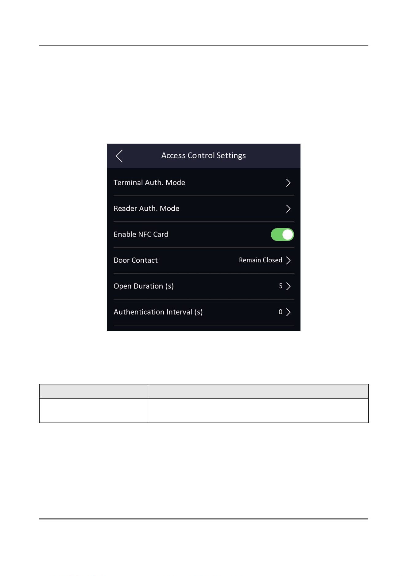
7.8 Set Access Control Parameters
You can set the access control permissions, including the funcons of authencaon mode, enable
NFC card, door contact, and door open me.
On the Home page, tap ACS (Access Control Sengs) to enter the Access Control Sengs page.
Edit the access control parameters on this page.
Figure 7-9 Access Control Parameters
The available parameters descripons are as follows:
Table 7-2 Access Control Parameters Descripons
Parameter Descripon
Terminal Auth. Mode (Terminal
Authencaon Mode)
Select the face recognion terminal's authencaon mode. You
can also customize the authencaon mode.
DS-K1TA70 Series Face Recognion Terminal User Manual
54
Parameter Descripon
Note
●
Biometric recognion products are not completely applicable
to an-spoong environments. If you require a higher
security level, use mulple authencaon modes.
●
If you adopt mulple authencaon modes, you should
authencate other methods before authencang face.
Reader Auth. Mode (Card
Reader Authencaon Mode)
Select the card reader's authencaon mode.
Enable NFC Card Enable the funcon and you can present the NFC card to
authencate.
Door Contact You can select "Open (Remain Open)" or "Close (Remian
Closed)" according to your actual needs. By default, it is Close
(Remian Closed).
Open Duraon Set the door unlocking duraon. If the door is not opened for
the set me, the door will be locked. Available door locked me
range: 1 to 255s.
Authencaon Interval Set the device authencang interval. Available authencaon
interval range: 0 to 65535.
7.9 Time and Aendance Status Sengs
You can set the aendance mode as check in, check out, break out, break in, overme in, and
overme out according to your actual situaon.
Note
The funcon should be used cooperavely with me and aendance funcon on the client
soware.
7.9.1 Disable Aendance Mode via Device
Disable the aendance mode and the system will not display the aendance status on the inial
page.
Tap T&A Status to enter the T&A Status page.
DS-K1TA70 Series Face Recognion Terminal User Manual
55
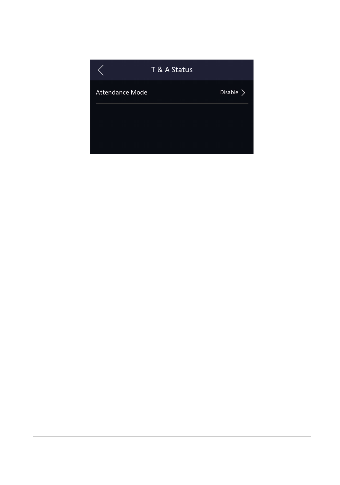
Figure 7-10 Disable Aendance Mode
Set the Aendance Mode as Disable.
You will not view or congure the aendance status on the inial page. And the system will follow
the aendance rule that congured on the plaorm.
7.9.2 Set Manual Aendance via Device
Set the aendance mode as manual, and you should select a status manually when you take
aendance.
Before You Start
Add at least one user, and set the user's authencaon mode. For details, see User Management.
Steps
1.
Tap T&A Status to enter the T&A Status page.
2.
Set the Aendance Mode as Manual.
DS-K1TA70 Series Face Recognion Terminal User Manual
56
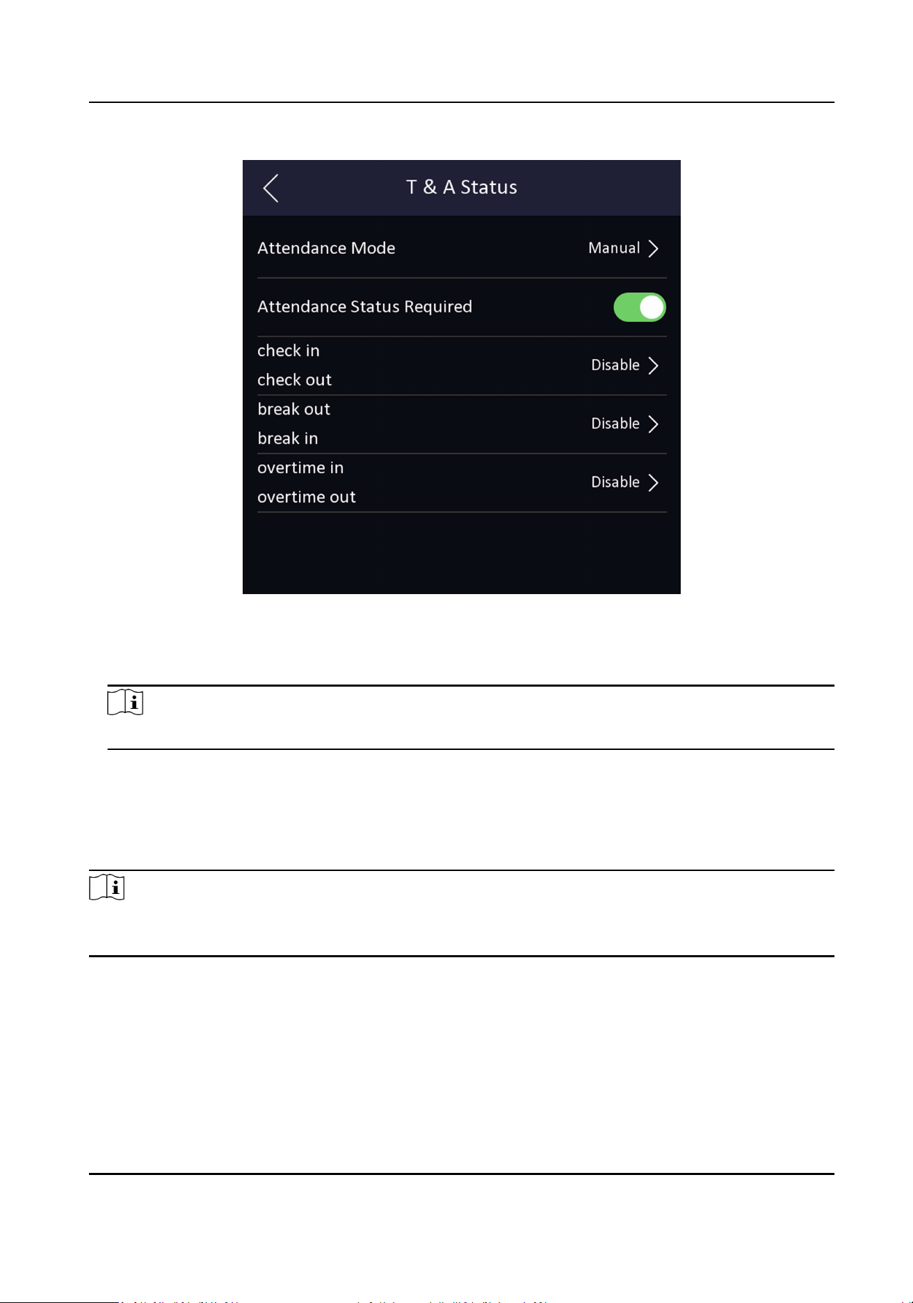
Figure 7-11 Manual Aendance Mode
3.
Enable the Aendance Status Required.
4.
Enable a group of aendance status.
Note
The Aendance Property will not be changed.
5.
Oponal: Select an status and change its name if required.
The name will be displayed on the T & A Status page and the authencaon result page.
Result
You should select an aendance status manually aer authencaon.
Note
If you do not select a status, the authencaon will be failed and it will not be marked as a valid
aendance.
7.9.3 Set Auto Aendance via Device
Set the aendance mode as auto, and you can set the aendance status and its available schedule.
The system will automacally change the aendance status according to the congured schedule.
DS-K1TA70 Series Face Recognion Terminal User Manual
57
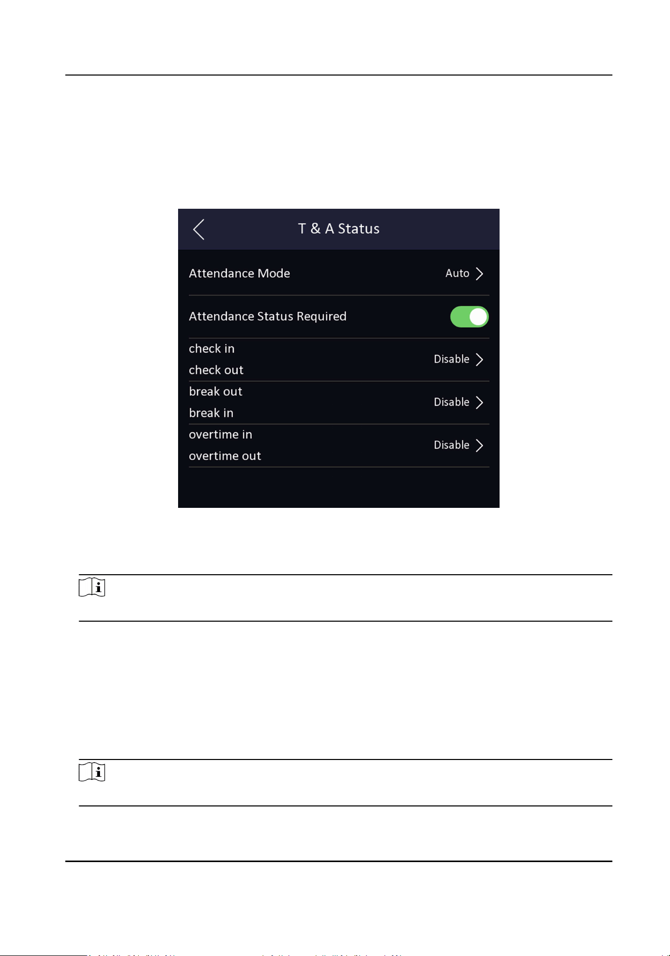
Before You Start
Add at least one user, and set the user's authencaon mode. For details, see User Management.
Steps
1.
Tap T&A Status to enter the T&A Status page.
2.
Set the Aendance Mode as Auto.
Figure 7-12 Auto Aendance Mode
3.
Enable the Aendance Status funcon.
4.
Enable a group of aendance status.
Note
The Aendance Property will not be changed.
5.
Oponal: Select an status and change its name if required.
The name will be displayed on the T & A Status page and the authencaon result page.
6.
Set the status' schedule.
1) Tap Aendance Schedule.
2) Select Monday, Tuesday, Wednesday, Thursday, Friday, Saturday, or Sunday.
3) Set the selected aendance status's start me of the day.
4) Tap Conrm.
5) Repeat step 1 to 4 according to your actual needs.
Note
The aendance status will be valid within the congured schedule.
DS-K1TA70 Series Face Recognion Terminal User Manual
58
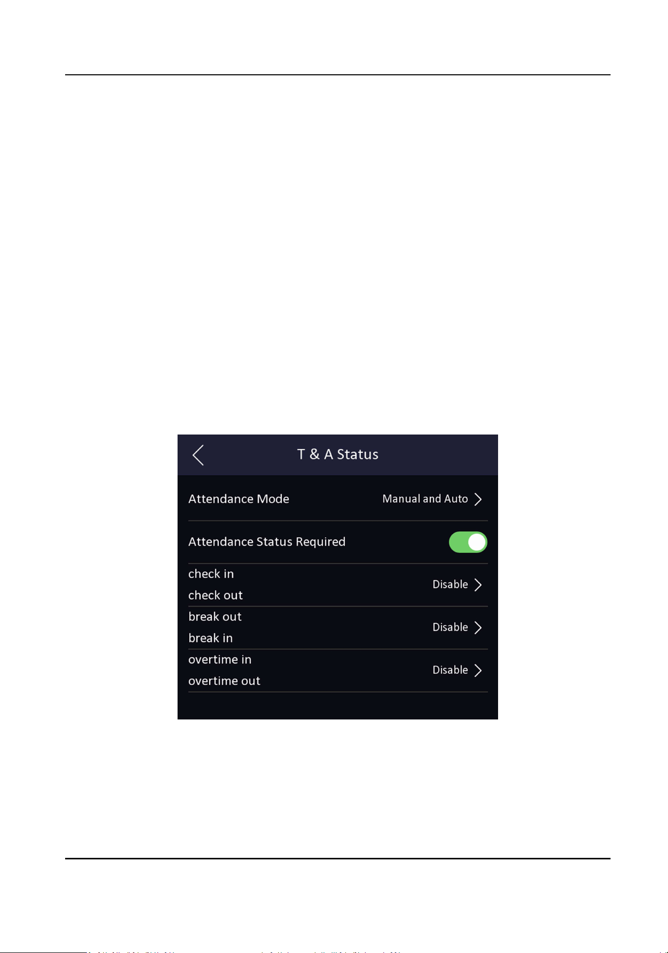
Result
When you authencate on the inial page, the authencaon will be marked as the congured
aendance status according to the congured schedule.
Example
If set the Break Out as Monday 11:00, and Break In as Monday 12:00, the valid user's
authencaon from Monday 11:00 to 12:00 will be marked as break.
7.9.4 Set Manual and Auto Aendance via Device
Set the aendance mode as Manual and Auto, and the system will automacally change the
aendance status according to the congured schedule. At the same me you can manually
change the aendance status aer the authencaon.
Before You Start
Add at least one user, and set the user's authencaon mode. For details, see User Management.
Steps
1.
Tap T&A Status to enter the T&A Status page.
2.
Set the Aendance Mode as Manual and Auto.
Figure 7-13 Manual and Auto Mode
3.
Enable the Aendance Status funcon.
4.
Enable a group of aendance status.
DS-K1TA70 Series Face Recognion Terminal User Manual
59
Note
The Aendance Property will not be changed.
5.
Oponal: Select an status and change its name if required.
The name will be displayed on the T & A Status page and the authencaon result page.
6.
Set the status' schedule.
1) Tap Aendance Schedule.
2) Select Monday, Tuesday, Wednesday, Thursday, Friday, Saturday, or Sunday.
3) Set the selected aendance status's start me of the day.
4) Tap OK.
5) Repeat step 1 to 4 according to your actual needs.
Note
The aendance status will be valid within the congured schedule.
Result
On the inial page and authencate. The authencaon will be marked as the congured
aendance status according to the schedule. If you tap the edit icon on the result tab, you can
select a status to take aendance manually, the authencaon will be marked as the edited
aendance status.
Example
If set the Break Out as Monday 11:00, and Break In as Monday 12:00, the valid user's
authencaon from Monday 11:00 to 12:00 will be marked as break.
7.10 System Maintenance
You can view the system informaon and the capacity. You can also upgrade the device, restore to
factory sengs, restore to default sengs, and reboot the device.
Long tap on the inial page for 3 s and slide to the le/right by following the gesture and login the
home page. Tap Maint..
Hold the ? on the upper-right corner of the page and enter the password to view the version of the
device.
DS-K1TA70 Series Face Recognion Terminal User Manual
60
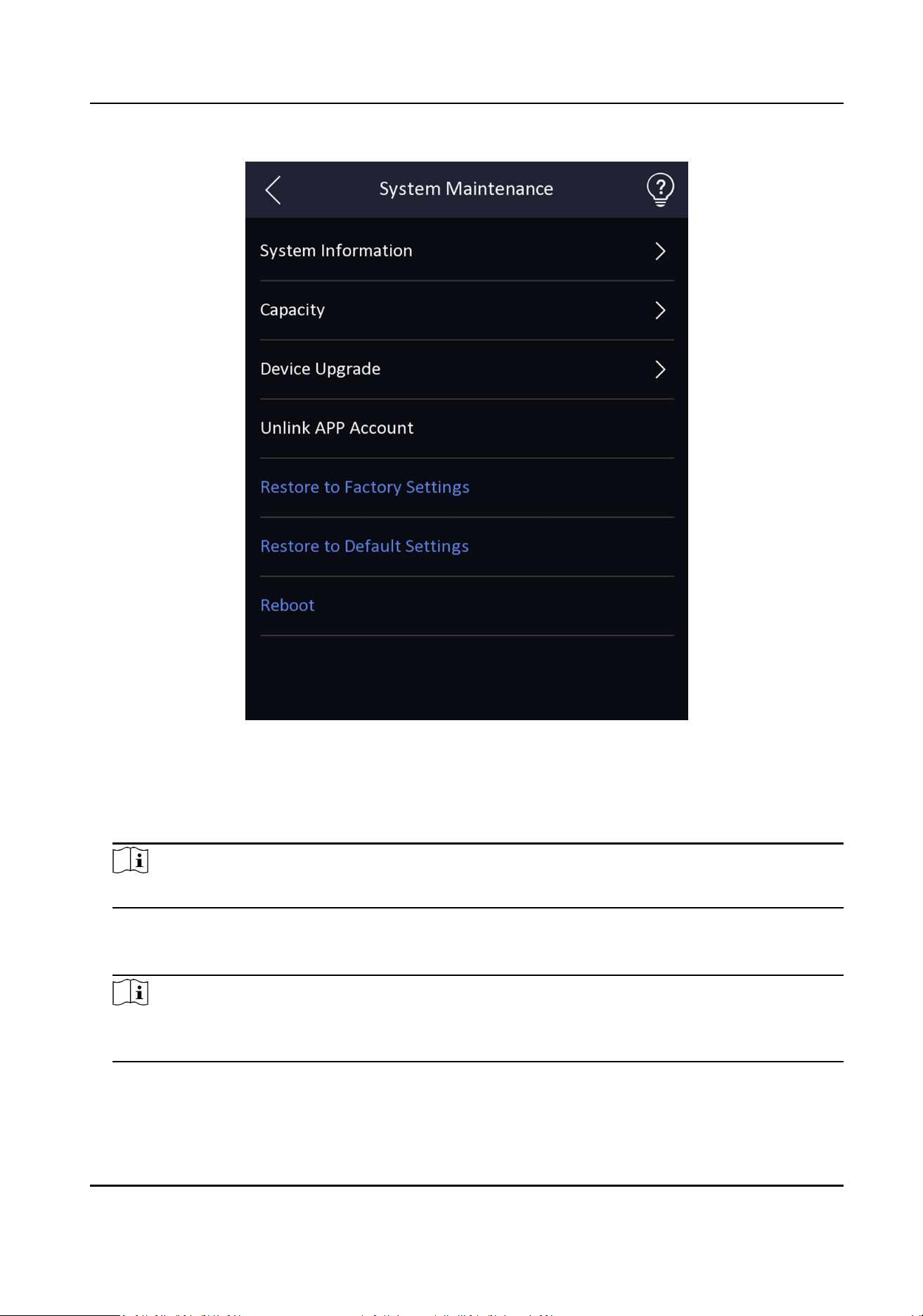
Figure 7-14 Maintenance Page
System Informaon
You can view the device model, serial No., versions, address, producon data, QR code, and
open source code license.
Note
The page may vary according to dierent device models. Refers to the actual page for details.
Capacity
You can view the number of, user, face picture, card, event and ngerprint.
Note
Parts of the device models support displaying the ngerprint number. Refers to the actual page
for details.
Device Upgrade
DS-K1TA70 Series Face Recognion Terminal User Manual
61
Online Update
If the device has been connected to Hik-Connect and network, when there is a new
installaon package in Hik-Connect, you can tap Device Upgrade → Online Update to
upgrade the device system.
Update via USB
Plug the USB ash drive in the device USB interface. Tap Device Upgrade → Update via USB ,
and the device will read the digicap.dav le in the USB ash drive to start upgrading.
Unlink APP Account
Aer unlinking APP account, you cannot operate via APP.
Restore to Default Sengs
All parameters, except for the communicaon sengs, remotely imported user informaon, will
be restored to the default sengs. The system will reboot to take eect.
Restore to Factory Sengs
All parameters will be restored to the factory sengs. The system will reboot to take eect.
Reboot
Reboot the device.
7.11 Video Intercom
Aer adding the device to the client soware, you can call the device from the client soware, call
the main staon from the device, call the client soware from the device, call the indoor staon
from the device, or call the specic room from the device.
7.11.1 Call Client Soware from Device
Steps
1.
Get the client soware from the supplied disk or the ocial website, and install the soware
according to the prompts.
2.
Run the client soware and the control panel of the soware pops up.
3.
Click Device Management to enter the Device Management interface.
4.
Add the device to the client soware.
Note
For details about adding device, see Add Device.
5.
Call the client soware.
1) Tap on the device inial page.
2) Enter 0 in the pop-up window.
3) Tap to call the client soware.
DS-K1TA70 Series Face Recognion Terminal User Manual
62
6.
Tap Answer on the pop-up page of the client soware and you can start two-way audio between
the device and the client soware.
Note
If the device is added to mulple client sowares and when the device is calling the client
soware, only the rst client soware added the device will pop up the call receiving window.
7.11.2 Call Center from Device
Steps
1.
Get the client soware from the supplied disk or the ocial website, and install the soware
according to the prompts.
2.
Run the client soware and the control panel of the soware pops up.
3.
Click Device Management to enter the Device Management interface.
4.
Add the main staon and the device to the client soware.
Note
For details about adding device, see Add Device.
5.
Set the main staon's IP address and SIP address in the remote conguraon page.
Note
For details about the operaon, see the user manual of the main staon.
6.
Call the center.
-
If you have congured to call center in the
Basic Sengs , you can tap to call the center.
-
If you have not congured to call center in the
Basic Sengs , you should tap → to call
the center
7.
Answers the call via the main staon and starts two-way audio.
Note
The device will call the main staon in priority.
7.11.3 Call Device from Client Soware
Steps
1.
Get the client soware from the supplied disk or the ocial website, and install the soware
according to the prompts.
2.
Run the client soware and the control panel of the soware pops up.
3.
Click Device Management to enter the Device Management page.
4.
Add the device to the client soware.
DS-K1TA70 Series Face Recognion Terminal User Manual
63
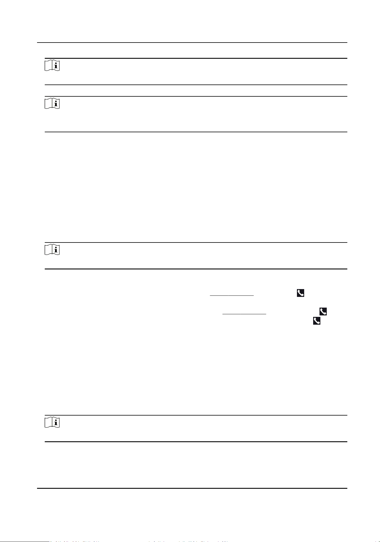
Note
For details about adding device, see Add Device.
5.
Enter the Live View page and double-click the added device to start live view.
Note
For details about operaons in the Live View page, see Live View in the user manual of the client
soware.
6.
Right click the live view image to open the right-click menu.
7.
Click Start Two-Way Audio to start two-way audio between the device and the client soware.
7.11.4 Call Room from Device
Steps
1.
Get the client soware from the supplied disk or the ocial website, and install the soware
according to the prompts.
2.
Run the client soware and the control panel of the soware pops up.
3.
Click Device Management to enter the Device Management interface.
4.
Add the indoor staon and the device to the client soware.
Note
For details about adding device, see Add Device.
5.
Link a user to an indoor staon and set a room No. for the indoor staon.
6.
Call the room.
-
If you have congured a specied room No. in the
Basic Sengs , you can tap to call the
room.
-
If you have not congured a specied room No. in the
Basic Sengs , you should tap on
the authencaon page of the device. Enter the room No. on the dial page and tap to call
the room.
7.
Aer the indoor staon answers the call, you can start two-way audio with the indoor staon.
7.11.5 Call Mobile Client from Device
Steps
1.
Get the mobile mobile client from the supplied disk or the ocial website, and install the
soware according to the prompts.
2.
Run the mobile client and add the device to the mobile client.
Note
For details, see the user manual of the mobile client.
3.
Enter Basic Sengs → Shortcut Key and enable Call APP.
4.
Go back to the inial page and call the mobile client.
DS-K1TA70 Series Face Recognion Terminal User Manual
64

1) Tap on the device inial page.
2) Tap to call the mobile client.
7.12 Temperature Measurement Sengs
You can set the temperature measurement parameters, including temperature detecon, over-
temperature alarm threshold, temperature compensaon, door not open when temperature is
abnormal, temperature measurement mode, temperature unit, etc.
On the Home page, tap Temperature to enter the Temperature page. Edit the temperature
measurement parameters on this page and tap to save the sengs.
DS-K1TA70 Series Face Recognion Terminal User Manual
65
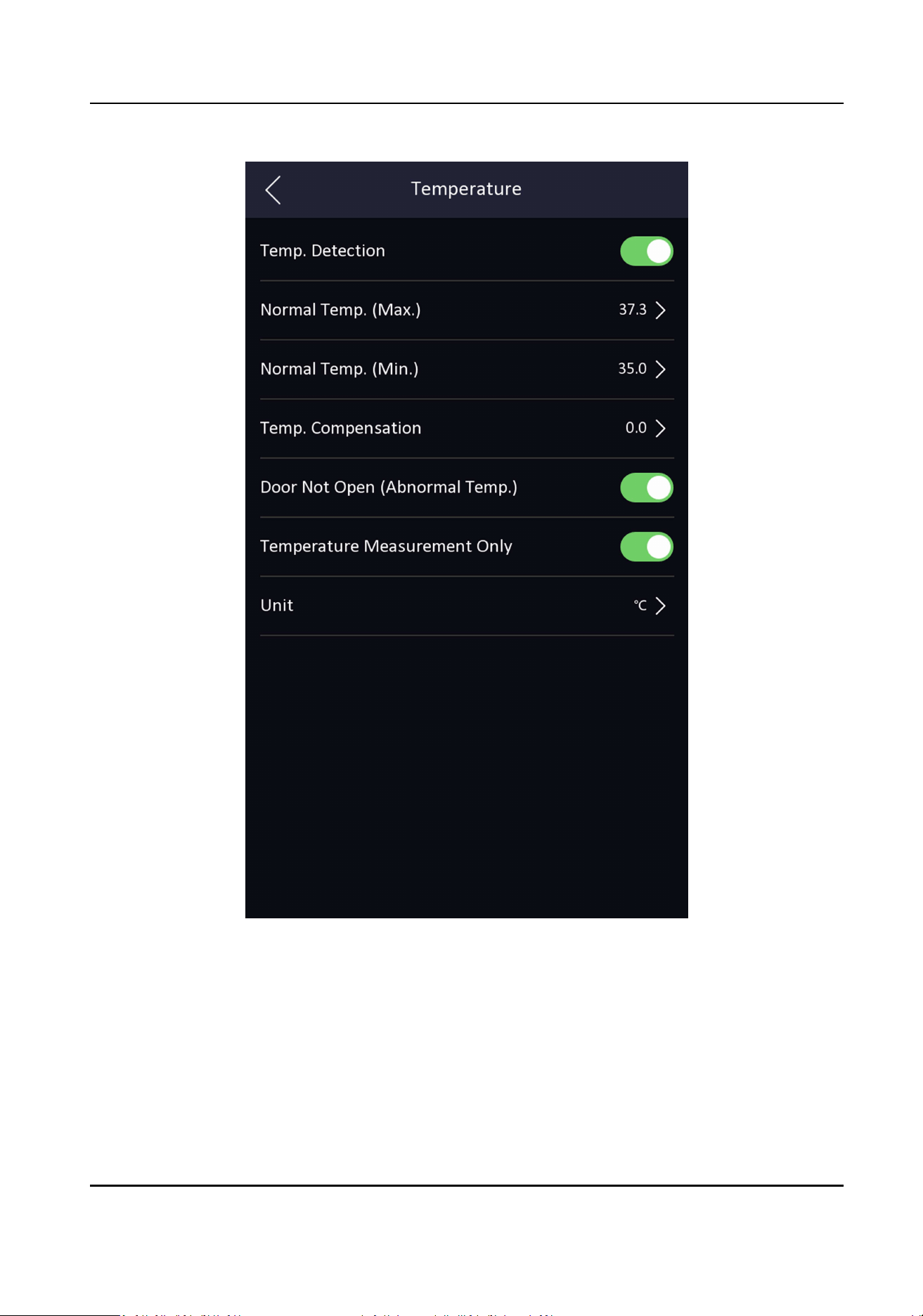
Figure 7-15 Temperature Measurement Parameters
The available parameters descripons are as follows:
DS-K1TA70 Series Face Recognion Terminal User Manual
66

Table 7-3 Temperature Measurement Parameters Descripons
Parameter Descripon
Temp. Detecon When enabling the funcon, the device will authencate the
permissions and at the same me take the temperature. When
disabling the device, the device will authencate the
permissions only.
Norm Temp. (Max./Min.) Edit the threshold according to actual situaon. If the detected
temperature is higher or lower than the congured parameters,
an alarm will be triggered. By default, the value is 37.3°.
Temp. Compensaon If the measured temperature is higher/lower than the actual
object's temperature, you can set the compensaon
temperature here. Available range: -99 °C to 99 °C
Door Not Open (Abnormal
Temp.)
When enabling the funcon, the door will not open when the
detected temperature is higher or lower than the congured
temperature threshold. By default, the funcon is enabled.
Temperature Measurement
Only
When enabling the funcon, the device will not authencate the
permissions, but only take the temperature. When disabling the
funcon, the device will authencate the permissions and at the
same me take the temperature.
Unit Select a temperature unit according to your preference.
Measurement Area Calibraon Congure the temperature measurement area.
DS-K1TA70 Series Face Recognion Terminal User Manual
67
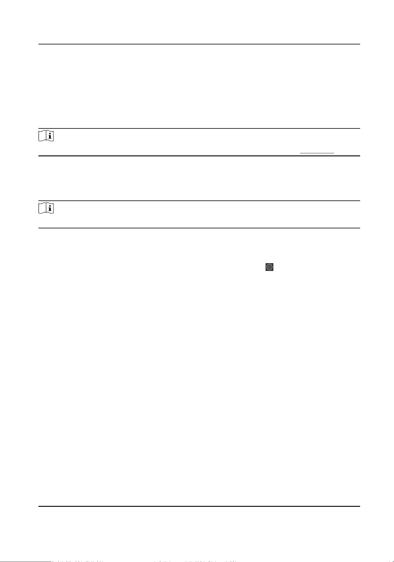
Chapter 8 Operaon via Web Browser
8.1 Login
You can login via the web browser or the remote conguraon of the client soware.
Note
Make sure the device is acvated. For detailed informaon about acvaon, see Acvaon .
Login via Web Browser
Enter the device IP address in the address bar of the web browser and press Enter to enter the
login page.
Note
Make sure that the IP address starts with "Hps:".
Enter the device user name and the password. Click Login.
Login via Remote Conguraon of Client Soware
Download and open the client soware. Aer adding the device, click to enter the Conguraon
page.
8.2 Live View
You can view the live video of the device.
Aer logging in, you will enter the live view page. You can perform the live view, capture, video
recording, and other operaons.
DS-K1TA70 Series Face Recognion Terminal User Manual
68
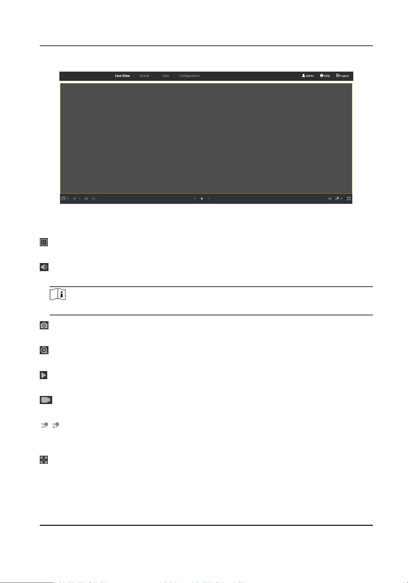
Figure 8-1 Live View Page
Funcon Descripons:
Select the image size when starng live view.
Set the volume when starng live view.
Note
If you adjust the volume when starng two-way audio, you may hear a repeated sounds.
You can capture image when starng live view.
Reserved funcon. You can zoom in the live view image.
Start or stop live view.
Start or stop video recording.
Select the streaming type when starng live view. You can select from the main stream and the
sub stream.
Full screen view.
DS-K1TA70 Series Face Recognion Terminal User Manual
69
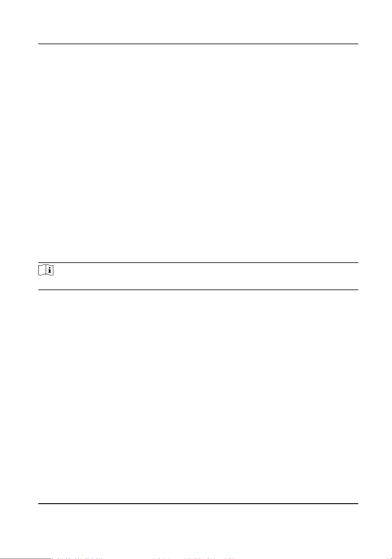
8.3 Person Management
Click and add the person's informaon, including the basic informaon, card, authencaon mode,
and the picture.
Click OK to save the person.
Add Basic Informaon
Click User → Add to enter the Add Person page.
Add the person's basic informaon, including the employee ID, the person's name, user level, oor
No., and room No.
Click OK to save the sengs.
Add Card
Click User → Add to enter the Add Person page.
Click Add Card and enter a card number.
Click OK to save the sengs.
Add Face Picture
Click User → Add to enter the Add Person page.
Click + on the right to upload a face picture from the local PC.
Note
The picture format should be JPG, JPEG or PNG. The size should be less than 200K.
Click OK to save the sengs.
Set Permission Time
Click User → Add to enter the Add Person page.
Set Start Time and End Time.
Click OK to save the sengs.
Set Access Control
Click User → Add to enter the Add Person page.
Aer check Adminstrator in Access Control, the added person can log in by authencang face.
Click OK to save the sengs.
Add Authencaon Mode
Click User → Add to enter the Add Person page.
Set the authencaon type.
Click OK to save the sengs.
DS-K1TA70 Series Face Recognion Terminal User Manual
70
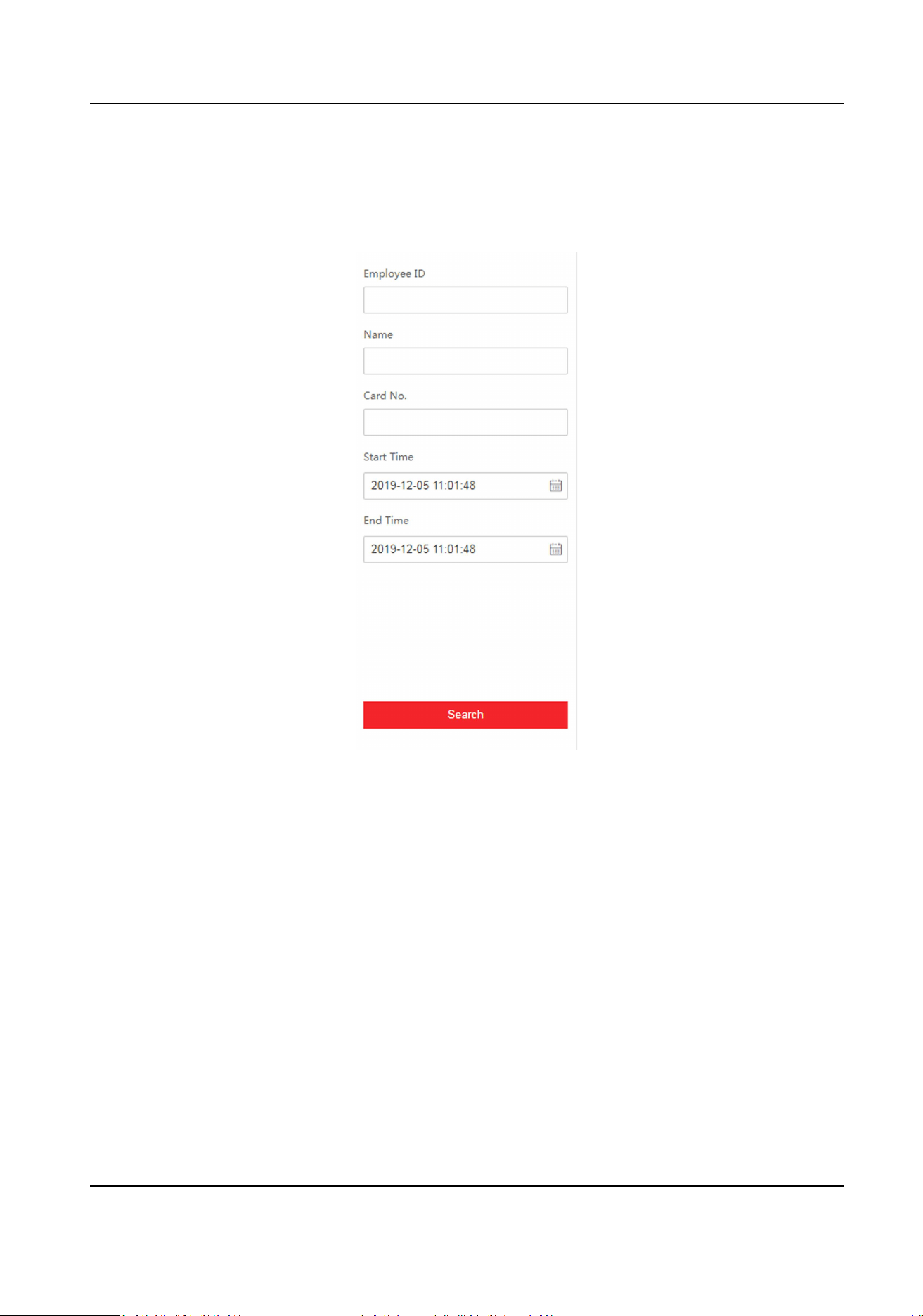
8.4 Search Event
Click Search to enter the Search page.
Figure 8-2 Search Page
Enter the search condions, including the employee ID, the name, the card No., the start me, and
the end me, and click Search.
The results will be displayed on the right panel.
8.5 Conguraon
8.5.1 Set Local Parameters
Set the live view parameters, record le size and saving path, and captured pictures and clip saving
path.
DS-K1TA70 Series Face Recognion Terminal User Manual
71
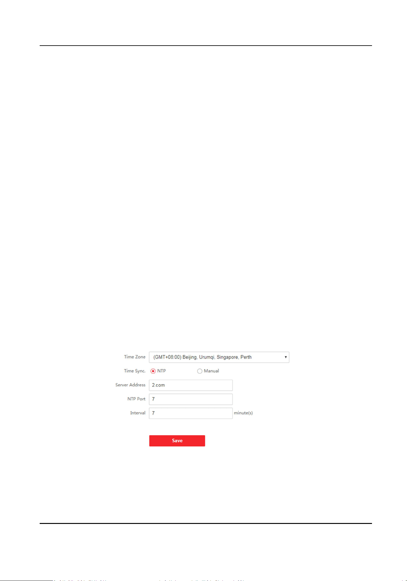
Set Live View Parameters
Click Conguraon → Local to enter the Local page. Congure the stream type, the play
performance, auto start live view, and the image format and click Save.
Set Record File Size and Saving Path
Click Conguraon → Local to enter the Local page. Select a record le size and select a saving
path from your local computer and click Save.
You can also click Open to open the le folder to view details.
Set Captured Pictures and Clips Saving Path
Click Conguraon → Local to enter the Local page. Select a saving path from your local computer
and click Save.
You can also click Open to open the le folder to view details.
8.5.2 View Device Informaon
View the device name, language, model, serial No., QR code, version, device capacity, etc.
Click Conguraon → System → System Sengs → Basic Informaon to enter the conguraon
page.
You can view the device name, language, model, serial No., QR code, version, device capacity, etc.
8.5.3 Set Time
Set the device's me zone, synchronizaon mode, and the device me.
Click Conguraon → System → System Sengs → Time Sengs .
Figure 8-3 Time Sengs
Click Save to save the sengs aer the conguraon.
DS-K1TA70 Series Face Recognion Terminal User Manual
72
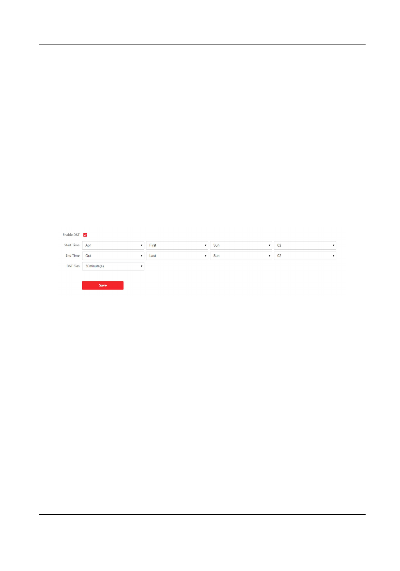
Time Zone
Select the device located me zone from the drop-down list.
Time Sync.
NTP
You should set the NTP server's IP address, port No., and interval.
Manual
By default, the device me should be synchronized manually. You can set the device me
manually or check Sync. with Computer Time to synchronize the device me with the
computer's me.
8.5.4 Set DST
Steps
1.
Click Conguraon → System → System Sengs → DST .
Figure 8-4 DST Page
2.
Check Enable DST.
3.
Set the DST start me, end me and bias me.
4.
Click Save to save the sengs.
8.5.5 View Open Source Soware License
Go to Conguraon → System → System Sengs → About Device , and click View Licenses to
view the device license.
8.5.6 Upgrade and Maintenance
Reboot device, restore device parameters, and upgrade device version.
Reboot Device
Click Conguraon → System → Maintenance → Upgrade & Maintenance .
DS-K1TA70 Series Face Recognion Terminal User Manual
73
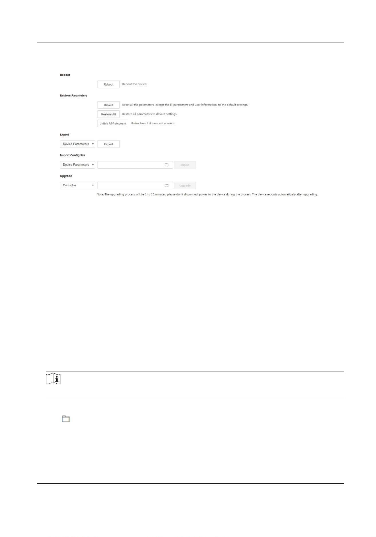
Figure 8-5 Upgrade and Maintenance Page
Click Reboot to start reboot the device.
Restore Parameters
Click Conguraon → System → Maintenance → Upgrade & Maintenance .
Default
The device will restore to the default sengs, except for the device IP address and the user
informaon.
Restore All
All parameters will be restored to the factory sengs. You should acvate the device before
usage.
Import and Export Parameters
Click Conguraon → System → Maintenance → Upgrade & Maintenance .
Export
Click Export to export the logs or device parameters.
Note
You can import the exported device parameters to another device.
Import
Click and select the le to import. Click Import to start import conguraon le.
Upgrade
Click Conguraon → System → Maintenance → Upgrade & Maintenance .
DS-K1TA70 Series Face Recognion Terminal User Manual
74

If the device has been connected to Hik-Connect and network, when there is a new installaon
package in Hik-Connect, you can click Upgrade aer Online Update to upgrade the device system.
Select an upgrade type from the drop-down list. Click and select the upgrade le from your
local PC. Click Upgrade to start upgrading.
Note
Do not power o during the upgrading.
8.5.7 Log Query
You can search and view the device logs.
Go to Conguraon → System → Maintenance → Log Query .
Set the major and minor type of the log type. Set the start me and end me for searching, and
click Search.
The results will be displayed below, which including the No., me, the major type the minor type,
the channel No., the local/remote user informaon, the remote host IP, etc.
8.5.8 Security Mode Sengs
Set the security mode for logging in the client soware.
On the Device for Management page, click Conguraon → System → Security → Security
Service .
Select a security mode from the drop-down list, and click Save.
Security Mode
High security level for user informaon vericaon when logging in the client soware.
Compable Mode
The user informaon vericaon is compable with the old client soware version when
logging in.
Enable SSH
To raise network security, disable SSH service. The conguraon is only used to debug the
device for the professionals.
Enable HTTPS
In order to increase the network security level when vising websites, you can enable HTTPS to
acquire a more secure and encrypted network communicaon environment. The
communicaon should authencated by identy and encrypon password aer enabling
HTTPS, which is save.
DS-K1TA70 Series Face Recognion Terminal User Manual
75

8.5.9 Cercate Management
It helps to manage the server/client cercates and CA cercate.
Note
The funcon is only supported by certain device models.
Create and Install Self-signed Cercate
Steps
1.
Go to Conguraon → System → Security → Cercate Management .
2.
In the Cercate Files area, select a Cercate Type from the drop-down list.
3.
Click Create.
4.
Input cercate informaon.
5.
Click OK to save and install the cercate.
The created cercate is displayed in the Cercate Details area.
The cercate will be saved automacally.
6.
Download the cercate and save it to an asking le in the local computer.
7.
Send the asking le to a cercaon authority for signature.
8.
Import the signed cercate.
1) Select a cercate type in the Import Passwords area, and select a cercate from the local,
and click Install.
2) Select a cercate type in the Import Communicaon Cercate area, and select a cercate
from the local, and click Install.
Install Other Authorized Cercate
If you already has an authorized cercate (not created by the device), you can import it to the
device directly.
Steps
1.
Go to Conguraon → System → Security → Cercate Management .
2.
In the Import Passwords and Import Communicaon Cercate areas, select cercate type
and upload cercate.
3.
Click Install.
Install CA Cercate
Before You Start
Prepare a CA cercate in advance.
DS-K1TA70 Series Face Recognion Terminal User Manual
76
Steps
1.
Go to Conguraon → System → Security → Cercate Management .
2.
Create an ID in the Inport CA Cercate area.
Note
The input cercate ID cannot be the same as the exisng ones.
3.
Upload a cercate le from the local.
4.
Click Install.
8.5.10 Change Administrator's Password
Steps
1.
Click Conguraon → User Management .
2.
Click .
3.
Enter the old password and create a new password.
4.
Conrm the new password.
5.
Click OK.
Cauon
The password strength of the device can be automacally checked. We highly recommend you
change the password of your own choosing (using a minimum of 8 characters, including at least
three kinds of following categories: upper case leers, lower case leers, numbers, and special
characters) in order to increase the security of your product. And we recommend you change
your password regularly, especially in the high security system, changing the password monthly
or weekly can beer protect your product.
Proper conguraon of all passwords and other security sengs is the responsibility of the
installer and/or end-user.
8.5.11 View Device Arming/Disarming Informaon
View device arming type and arming IP address.
Go to Conguraon → Arming/Disarming Informaon .
You can view the device arming/disarming informaon. Click Refresh to refresh the page.
8.5.12 Network Sengs
Set TCP/IP, port, report strategy and plaorm access.
DS-K1TA70 Series Face Recognion Terminal User Manual
77
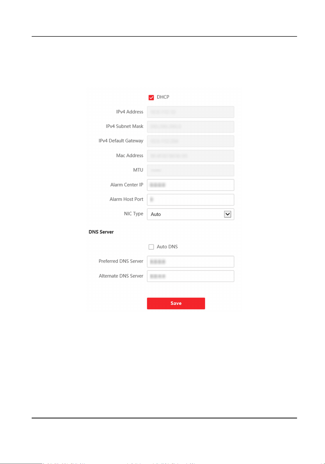
Set Basic Network Parameters
Click Conguraon → Network → Basic Sengs → TCP/IP .
Figure 8-6 TCP/IP Sengs Page
Set the parameters and click Save to save the sengs.
DHCP
If uncheck the funcon, you should set the IPv4 address, IPv4 subnet mask, IPv4 default
gateway, MTU, and the device port.
If you check the funcon, the system will allocate the IPv4 address, IPv4 subnet mask, and the
IPv4 default gateway automacally.
NIC Type
DS-K1TA70 Series Face Recognion Terminal User Manual
78

Select a NIC type from the drop-down list. By default, it is Auto.
DNS Server
Set the preferred DNS server and the Alternate DNS server according to your actual need.
Set Port Parameters
Set the HTTP, RTSP, HTTPS and Server port parmaeters.
Click Conguraon → Network → Basic Sengs → Port .
HTTP
It refers to the port through which the browser accesses the device. For example, when the
HTTP Port is modied to 81, you need to enter hp://192.0.0.65:81 in the browser for login.
RTSP
It refers to the port of real-me streaming protocol.
HTTPS
Set the HTTPS for accessing the browser. Cercate is required when accessing.
Server
It refers to the port through which the client adds the device.
Report Strategy Sengs
You can set the center group for uploading the log via the ISUP protocol.
Go to Conguraon → Network → Basic Sengs → Report Strategy .
You can set the center group and the system will transfer logs via ISUP protocol. Click Save to save
the sengs.
Center Group
Select a center group from the drop-down list.
Main Channel
The device will communicate with the center via the main channel.
Note
N1 refers to wired network.
Plaorm Access
Plaorm access provides you an opon to manage the devices via plaorm.
Steps
1.
Click Conguraon → Network → Advanced → Plaorm Access to enter the sengs page.
DS-K1TA70 Series Face Recognion Terminal User Manual
79
2.
Check the checkbox of Enable to enable the funcon.
3.
Select the Plaorm Access Mode.
Note
Hik-Connect is an applicaon for mobile devices. With the App, you can view live image of the
device, receive alarm nocaon and so on.
4.
Create a Stream Encrypon/Encrypon Key for the device.
Note
6 to 12 leers (a to z, A to Z) or numbers (0 to 9), case sensive. You are recommended to use a
combinaon of no less than 8 leers or numbers.
5.
Click Save to enable the sengs.
Set ISUP Parameters
Set the ISUP parameters for accessing device via ISUP protocol.
Steps
Note
The funcon should be supported by the device.
1.
Click Conguraon → Network → Advanced Sengs → Plaorm .
2.
Select ISUP from the plaorm access mode drop-down list.
3.
Check Enable.
4.
Set the ISUP version, server address, device ID, and the ISUP status.
Note
If you select 5.0 as the version, you should set the ISUP key as well.
5.
Click Save.
Congure HTTP Listening
The device can send alarm informaon to the desnaon IP or host via HTTP protocol/HTTPS
protocol.
Before You Start
The desnaon IP or host name should support the HTTP protocol/HTTPS protocol to receive the
alarm informaon.
Note
The funcon should be supported by the device.
DS-K1TA70 Series Face Recognion Terminal User Manual
80
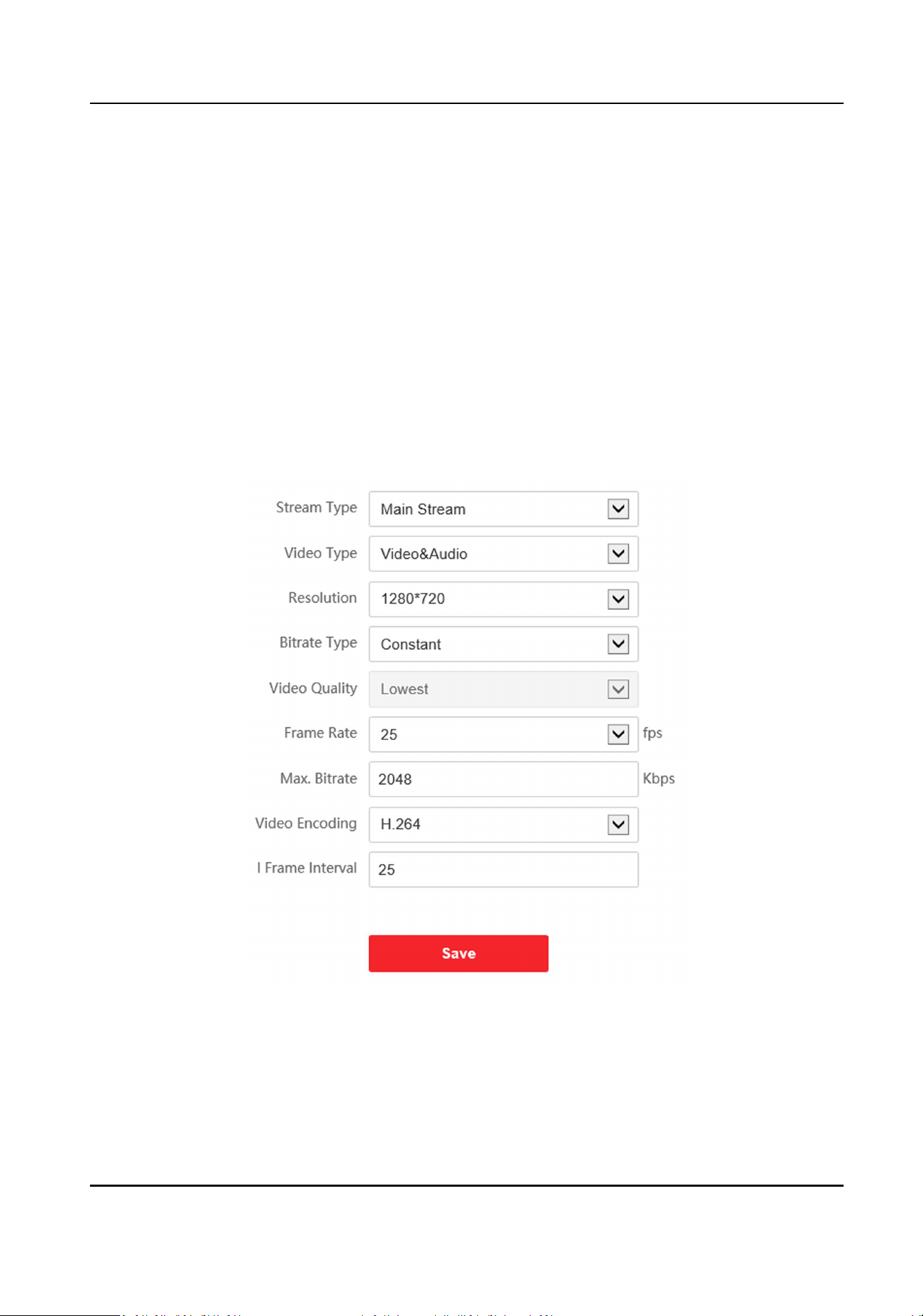
Steps
1.
Click Conguraon → Network → Advanced → HTTP Listening .
2.
Edit the desnaon IP or host name, URL and port.
3.
Oponal: Click Test to test whether the entered IP address or host name are valid.
4.
Oponal: Click Default to reset the desnaon IP or host name.
5.
Click Save.
8.5.13 Set Video and Audio Parameters
Set the image quality, resoluon, and the device volume.
Set Video Parameters
Click Conguraon → Video/Audio → Video .
Figure 8-7 Video Sengs Page
Set the stream type, the video type, the bitrate type, the frame rate, the Max. bitrate, the video
encoding, and I Frame Interval.
Click Save to save the sengs aer the conguraon.
DS-K1TA70 Series Face Recognion Terminal User Manual
81
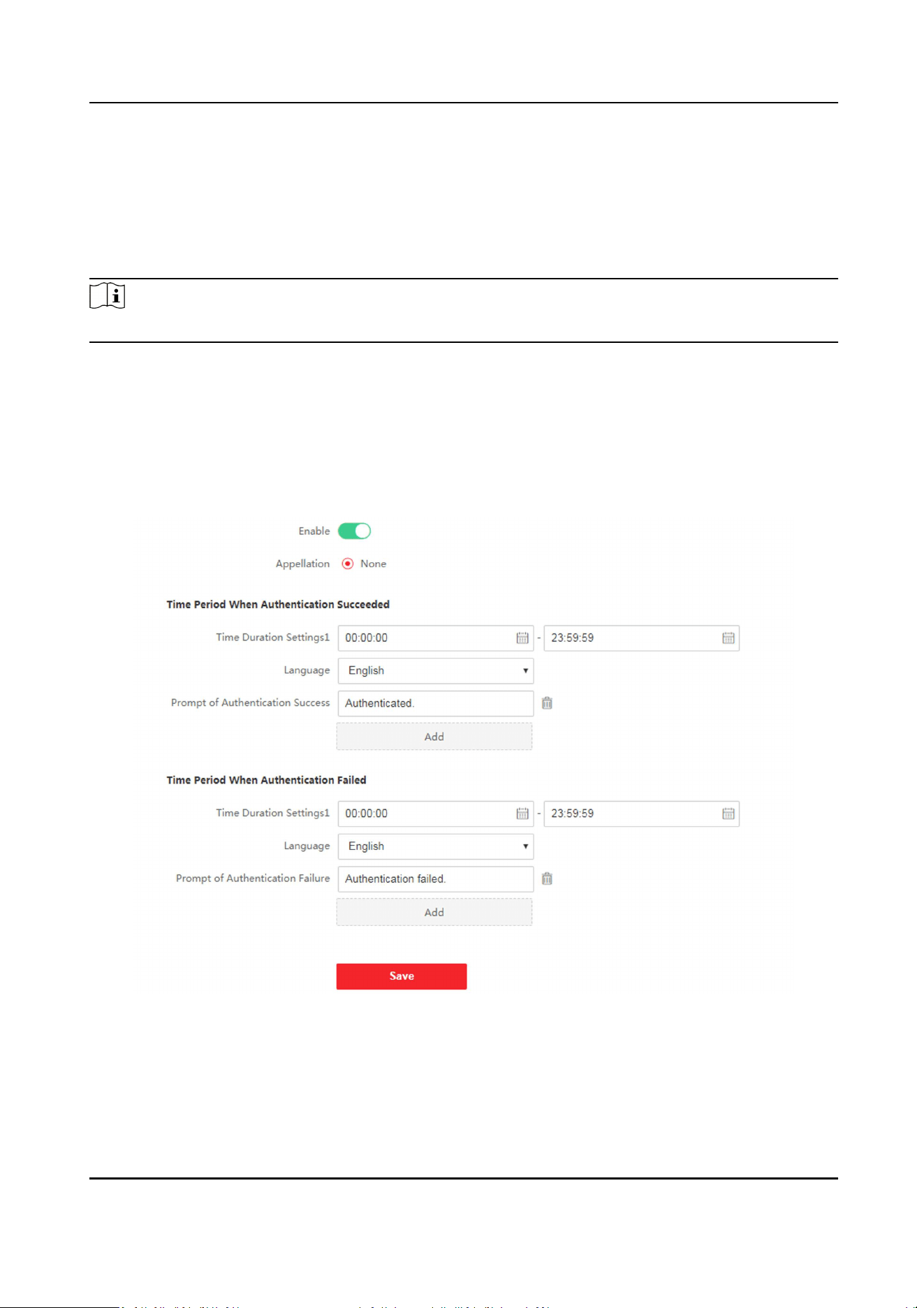
Set Audio Parameters
Click Conguraon → Video/Audio → Audio .
Set the audio stream type and audio encoding.
You can also drag the block to adjust the device input and output volume.
Click Save to save the sengs aer the conguraon.
Note
The funcons vary according to dierent models. Refers to the actual device for details.
8.5.14 Customize Audio Content
Customize the output audio content when authencaon succeeded and failed.
Steps
1.
Click Conguraon → Video/Audio → Prompt .
Figure 8-8 Customize Audio Content
2.
Set the appellaon.
3.
Enable the funcon.
4.
Set the me duraon when authencaon succeeded.
DS-K1TA70 Series Face Recognion Terminal User Manual
82
1) Click Add.
2) Set the me duraon and the language.
Note
If authencaon is succeeded in the congured me duraon, the device will broadcast the
congured content.
3) Enter the audio content.
4) Oponal: Repeat substep 1 to 3.
5) Oponal: Click to delete the congured me duraon.
5.
Set the me duraon when authencaon failed.
1) Click Add.
2) Set the me duraon and the language.
Note
If authencaon is failed in the congured me duraon, the device will broadcast the
congured content.
3) Enter the audio content.
4) Oponal: Repeat substep 1 to 3.
5) Oponal: Click to delete the congured me duraon.
6.
Oponal: Import custom prompt.
1) Select Custom Type.
2) Select the imporng path, and click Import.
7.
Click Save to save the sengs.
8.5.15 Set Image Parameters
Set the video standard, WDR, brightness, contrast, saturaon, and sharpness.
Steps
1.
Click Conguraon → Image Adjustment .
DS-K1TA70 Series Face Recognion Terminal User Manual
83
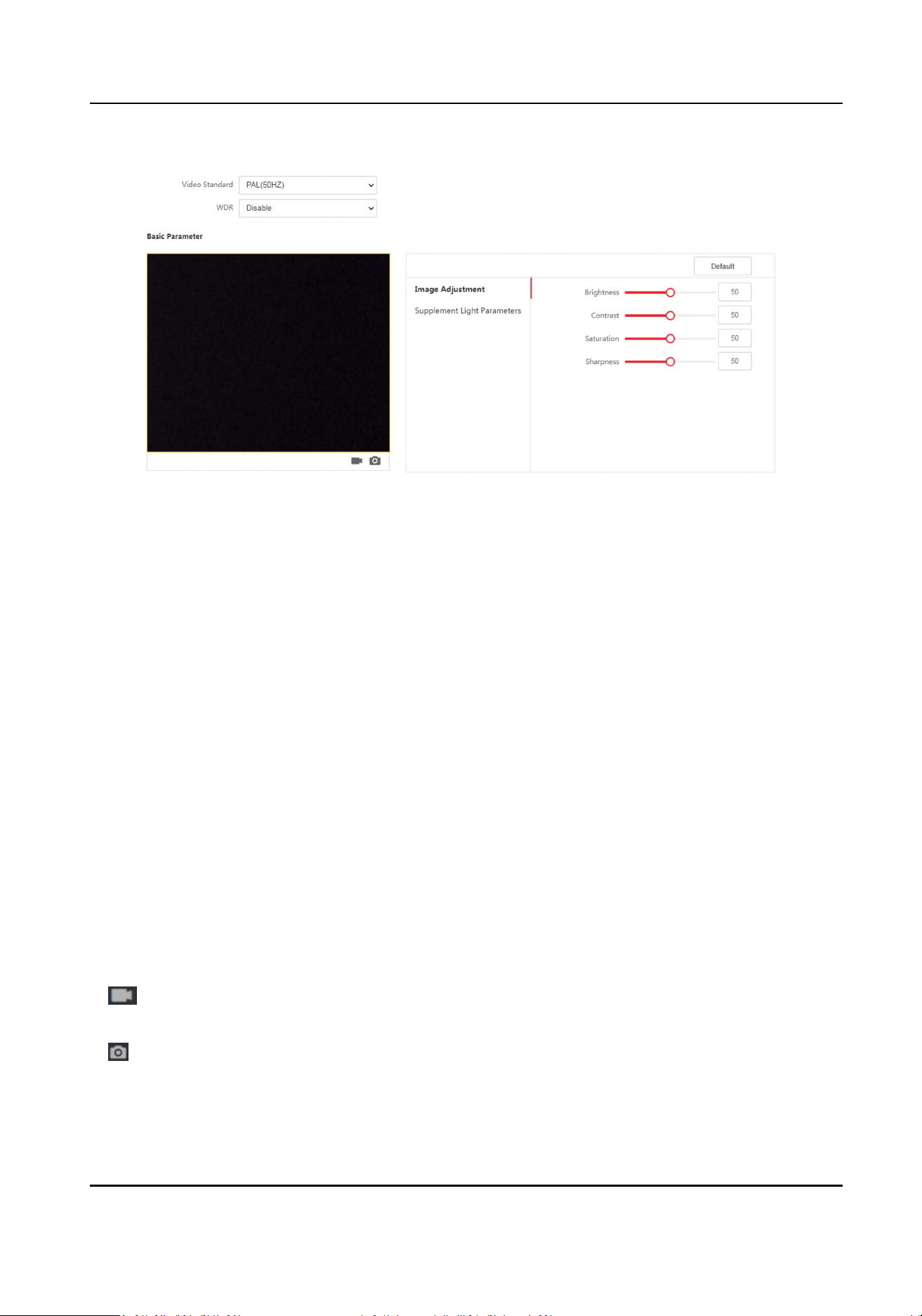
Figure 8-9 Image Sengs Page
2.
Congure the parameters to adjust the image.
Video Standard
Set the video frame rate when performing live view remotely. Aer changing the standard,
you should reboot the device to take eect.
PAL
25 frames per second. Suitable for mainland China, Hong Kong (China), the Middle East
countries, Europe countries, etc.
NTSC
30 frames per second. Suitable for the USA, Canada, Japan, Taiwan (China), Korea, the
Philippines, etc.
WDR
Enable or disable the WDR funcon.
When there are both very bright and very dark areas simultaneously in the view, WDR
balances the brightness level of the whole image and provide clear images with details.
Brightness/Contrast/Saturaon/Sharpness
Drag the block or enter the value to adjust the live video's brightness, contrast, saturaon,
and sharpness.
Start/end recording video.
Capture the image.
3.
Click Default to restore the parameters to the default sengs.
DS-K1TA70 Series Face Recognion Terminal User Manual
84
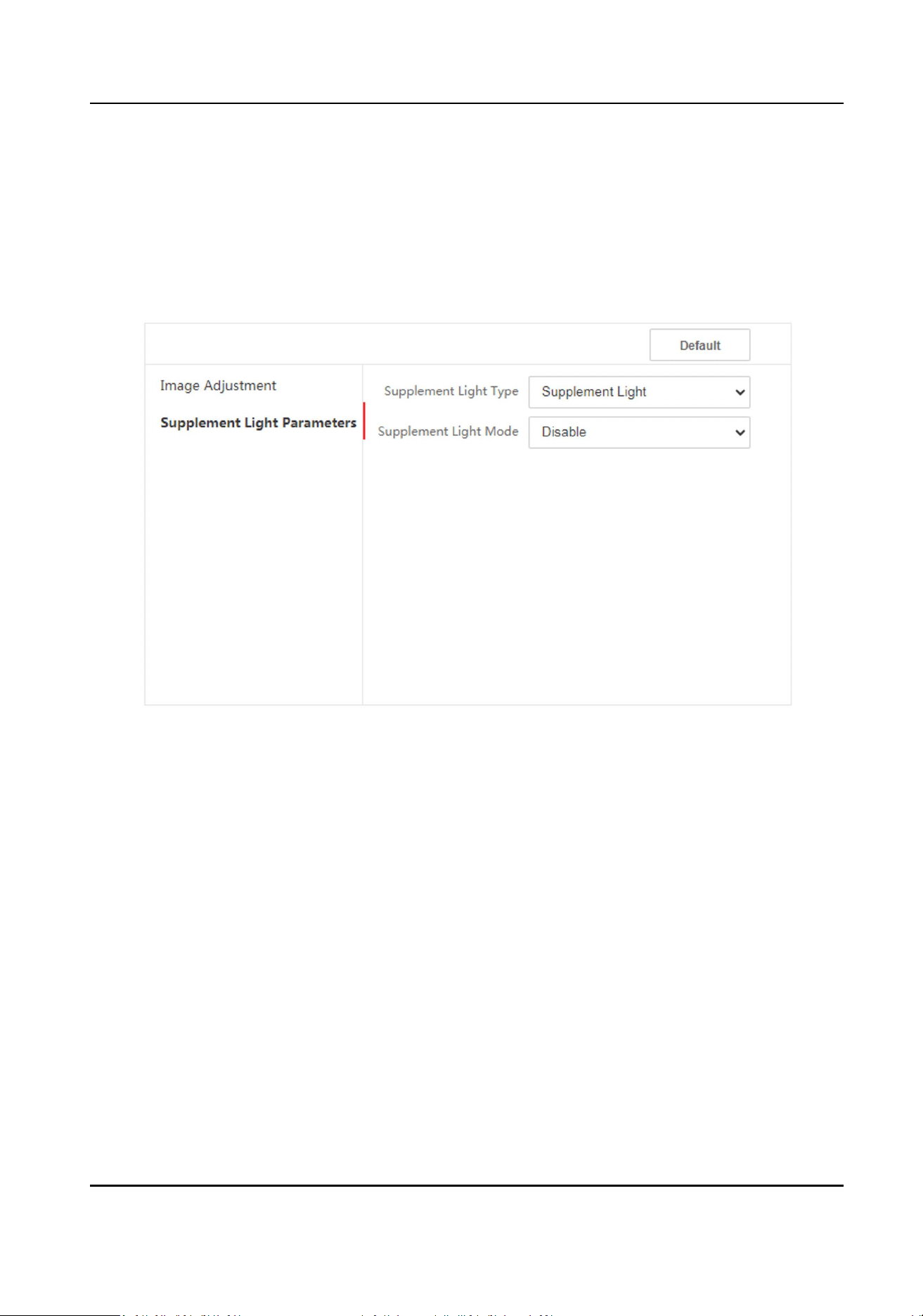
8.5.16 Set Supplement Light Brightness
Set the device supplement light brightness.
Steps
1.
Click Conguraon → Image → Supplement Light Parameters .
Figure 8-10 Supplement Light Sengs Page
2.
Select a supplement light type and mode from the drop-down list. If you select the mode as ON,
you should set the brightness.
8.5.17 Time and Aendance Sengs
If you want to track and monitor when the persons start/stop work and monitor their working
hours and late arrivals, early departures, me taken on breaks, and absenteeism, you can add the
person to the shi group and assign a shi schedule (a rule for the aendance dening how the
schedule repeats, the shi type, break sengs, and the card swiping rule.) to the shi group to
dene the aendance parameters for the persons in the shi group.
DS-K1TA70 Series Face Recognion Terminal User Manual
85
Disable Aendance Mode via Web
Disable the aendance mode and the system will not display the aendance status on the inial
page.
Steps
1.
Click Conguraon → Aendance to enter the sengs page.
2.
Set the Aendance Mode as Disable.
Result
You will not view or congure the aendance status on the inial page. And the system will follow
the aendance rule that congured on the plaorm.
Time Sengs
Steps
1.
Click Conguraon → Time Sengs to enter the sengs page.
2.
Select Status Type.
3.
Oponal: Edit Schedule Name according to the actual needs.
4.
Drag mouse to set the schedule.
Note
Set the schedule from Monday to Sunday according to the actual needs.
5.
Oponal: Select a meline and click Delete. Or click Delete All to clear the sengs.
6.
Click Save.
Set Manual Aendance via Web
Set the aendance mode as manual, and you should select a status manually when you take
aendance.
Before You Start
Add at least one user, and set the user's authencaon mode. For details, see User Management.
Steps
1.
Click Conguraon → Aendance to enter the sengs page.
2.
Set the Aendance Mode as Manual.
3.
Enable the Aendance Status Required and set the aendace status lasts duraon.
4.
Enable a group of aendance status.
Note
The Aendance Property will not be changed.
5.
Oponal: Select an status and change its name if required.
DS-K1TA70 Series Face Recognion Terminal User Manual
86
Result
You should select an aendance status manually aer authencaon.
Note
If you do not select a status, the authencaon will be failed and it will not be marked as a valid
aendance.
Set Auto Aendance via Web
Set the aendance mode as auto, and you can set the aendance status and its available schedule.
The system will automacally change the aendance status according to the congured schedule.
Before You Start
Add at least one user, and set the user's authencaon mode. For details, see User Management.
Steps
1.
Click Conguraon → Aendance to enter the sengs page.
2.
Set the Aendance Mode as Auto.
3.
Enable the Aendance Status funcon.
4.
Enable a group of aendance status.
Note
The Aendance Property will not be changed.
5.
Oponal: Select an status and change its name if required.
6.
Set the status' schedule. Refers to
Time Sengs for details.
Set Manual and Auto Aendance via Web
Set the aendance mode as Manual and Auto, and the system will automacally change the
aendance status according to the congured schedule. At the same me you can manually
change the aendance status aer the authencaon.
Before You Start
Add at least one user, and set the user's authencaon mode. For details, see User Management.
Steps
1.
Click Conguraon → Aendance to enter the sengs page.
2.
Set the Aendance Mode as Manual and Auto.
3.
Enable the Aendance Status funcon.
4.
Enable a group of aendance status.
Note
The Aendance Property will not be changed.
DS-K1TA70 Series Face Recognion Terminal User Manual
87
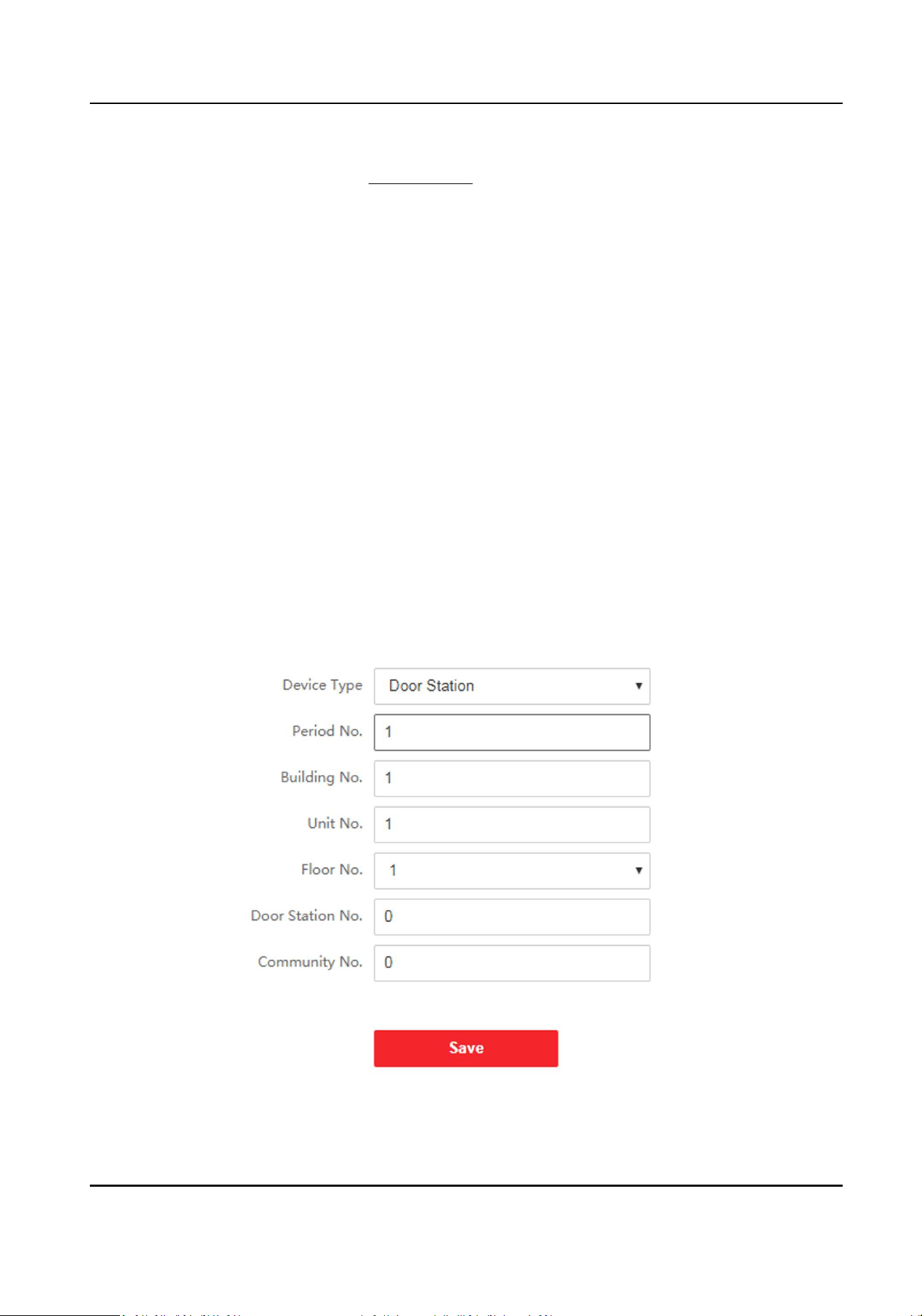
5.
Oponal: Select an status and change its name if required.
6.
Set the status' schedule. Refers to Time Sengs for details.
Result
On the inial page and authencate. The authencaon will be marked as the congured
aendance status according to the schedule. If you tap the edit icon on the result tab, you can
select a status to take aendance manually, the authencaon will be marked as the edited
aendance status.
Example
If set the Break Out as Monday 11:00, and Break In as Monday 12:00, the valid user's
authencaon from Monday 11:00 to 12:00 will be marked as break.
8.5.18 Set Video Intercom Parameters
The device can be used as a door staon, outer door staon, or access control device. You should
set the device No. before usage.
Click Conguraon → Video Intercom → Device No. .
If set the device type as Door Staon or Access Control Device, you can set the period No.,
building No., unit No., oor No., door staon No., and community No.
Click Save to save the sengs aer the conguraon.
Figure 8-11 Device No. Sengs
DS-K1TA70 Series Face Recognion Terminal User Manual
88
Device Type
The device can be used as a door staon or outer door staon. Select a device type from the
drop-down list.
Note
If you change the device type, you should reboot the device.
Period No.
Set the device installed period No.
Building No.
Set the device installed building No.
Unit No.
Set the device installed unit No.
Floor No.
Set the device installed oor No.
Door Staon No.
Set the device installed oor No.
Note
If you change the No., you should reboot the device.
Community No.
Set the device installed community No.
If set the device type as Outer Door Staon, you can set the period No., outer door staon No.,
and community No.
Period No.
Set the device installed period No.
Outer Door Staon No.
If you select outer door staon as the device type, you should enter a number between 1 and
99.
Note
If you change the No., you should reboot the device.
Community No.
Set the device installed community No.
DS-K1TA70 Series Face Recognion Terminal User Manual
89

8.5.19 Access Control Sengs
Set Authencaon Parameters
Click Conguraon → Access Control → Authencaon Sengs .
Note
The funcons vary according to dierent models. Refers to the actual device for details.
Click Save to save the sengs aer the conguraon.
Device Type
Select Main Card Reader or Sub Card Reader from the drop-down list.
Main Card Reader
You can congure the device card reader's parameters.
Sub Card Reader
You can congure the connected peripheral card reader's parameters.
If select Main Card Reader:
Card Reader Type/Card Reader Descripon
Get card reader type and descripon. They are read-only.
Enable Card Reader
Enable the card reader's funcon.
Authencaon
Select an authencaon mode according to your actual needs from the drop-down list.
Recognion Interval
You can set the interval between 2 connuous recognion of a same person during the
authencaon. In the congured interval, Person A can only recognized once. If another person
(Person B) has recognized during the interval, Person A can recognized again.
Authencaon Interval
You can set the authencaon interval of the same person when authencang. The same
person can only authencate once in the congured interval. A second authencaon will be
failed.
Alarm of Max. Failed Aempts
Enable to report alarm when the card reading aempts reach the set value.
Enable Tampering Detecon
Enable the an-tamper detecon for the card reader.
Enable Card No. Reversing
DS-K1TA70 Series Face Recognion Terminal User Manual
90

The read card No. will be in reverse sequence aer enabling the funcon.
If select Sub Card Reader:
Card Reader Type/Card Reader Descripon
Get card reader type and descripon. They are read-only.
Enable Card Reader
Enable the card reader's funcon.
Authencaon
Select an authencaon mode according to your actual needs from the drop-down list.
Recognion Interval
If the interval between card presenng of the same card is less than the congured value, the
card presenng is invalid.
Authencaon Interval
You can set the authencaon interval of the same person when authencang. The same
person can only authencate once in the congured interval. A second authencaon will be
failed.
Alarm of Max. Failed Aempts
Enable to report alarm when the card reading aempts reach the set value.
Communicaon with Controller Every
When the access control device cannot connect with the card reader for longer than the set
me, the card reader will turn oine automacally.
Max. Interval When Entering Password
When you entering the password on the card reader, if the interval between pressing two digits
is longer than the set value, the digits you pressed before will be cleared automacally.
OK LED Polarity/Error LED Polarity
Set OK LED Polarity/Error LED Polarity of the access control device according to the card reader
parameters. Generally, adopts the default sengs.
Enable Tampering Detecon
Enable the an-tamper detecon for the card reader.
Set Door Parameters
Click Conguraon → Access Control → Door Parameters .
DS-K1TA70 Series Face Recognion Terminal User Manual
91
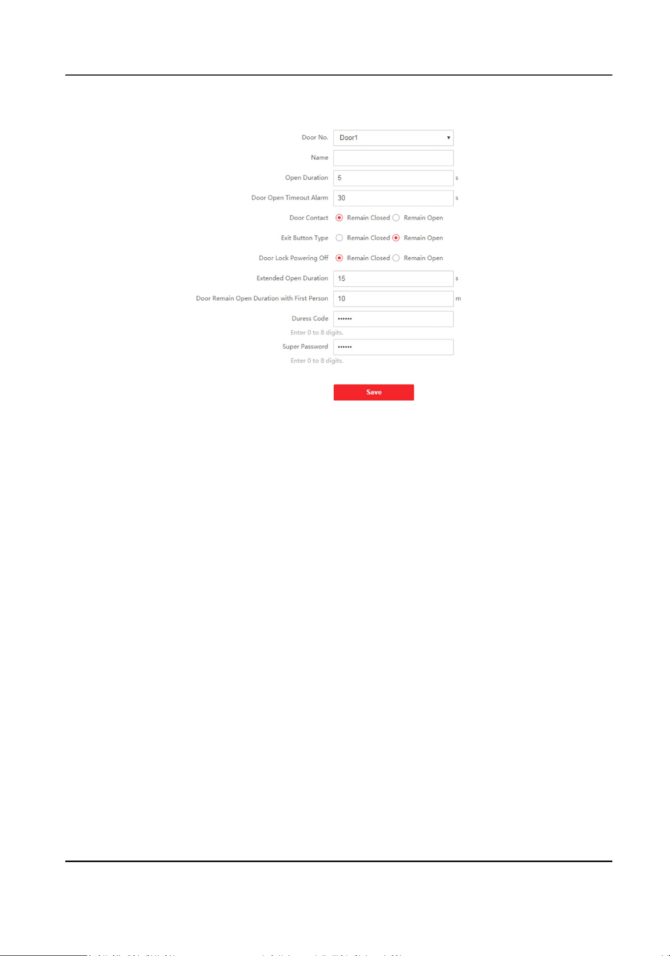
Figure 8-12 Door Parameters Sengs Page
Click Save to save the sengs aer the conguraon.
Door No.
Select the device corresponded door No.
Name
You can create a name for the door.
Open Duraon
Set the door unlocking duraon. If the door is not opened for the set me, the door will be
locked.
Door Open Timeout Alarm
An alarm will be triggered if the door has not been closed within the congured me duraon.
Door Contact
You can set the door contact as Remain Open or Remain Closed according to your actual needs.
By default, it is Remain Closed.
Exit Buon Type
You can set the exit buon as Remain Open or Remain Closed according to your actual needs.
By default, it is Remain Open.
Door Lock Powering O Status
DS-K1TA70 Series Face Recognion Terminal User Manual
92
You can set the door lock status when the door lock is powering o. By default, it is Remain
Closed.
Extended Open Duraon
The door contact can be enabled with appropriate delay aer person with extended access
needs swipes her/his card.
Door Remain Open Duraon with First Person
Set the door open duraon when rst person is in. Aer the rst person is authorized, it allows
mulple persons access the door or other authencaon acons.
Duress Code
The door can open by inpung the duress code when there is duress. At the same me, the
client can report the duress event.
Super Password
The specic person can open the door by inpung the super password.
Note
The duress code and the super code should be dierent.
Set Card Security
Click Conguraon → Access Control → Card Security to enter the sengs page.
Set the parameters and click Save.
Enable NFC Card
In order to prevent the mobile phone from geng the data of the access control, you can
enable NFC card to increase the security level of the data.
Enable M1 Card
Enable M1 card and authencang by presenng M1 card is available.
M1 Card Encrypon
Sector
M1 card encrypon can improve the security level of authencaon.
Enable the funcon and set the encrypon sector. By default, Sector 13 is encrypted. It is
recommended to encrypt sector 13.
Enable EM Card
Enable EM card and authencang by presenng EM card is available.
Note
If the peripheral card reader supports presenng EM card, the funcon is also supported to
enable/disable the EM card funcon.
DS-K1TA70 Series Face Recognion Terminal User Manual
93
Congure SIP Parameters
Set the device's IP address and the SIP server's IP address. Aer seng the parameters, you can
communicate among the access control device, door staon, indoor staon, main staon, and the
plaorm.
Note
Only the access control device and other devices or systems (such as door staon, indoor staon,
main staon, plaorm) are in the same IP segment, the two-way audio can be performed.
Go to Conguraon → Access Control → Linked Network Sengs .
Set the main staon's IP address and SIP server's IP address.
Click Save.
Set RS-485 Parameters
You can set the RS-485 parameters including the peripheral, address, baud rate, etc.
Click Conguraon → Access Control → RS-485 Sengs .
Click Save to save the sengs aer the conguraon.
No.
Set the RS-485 No.
Peripheral Type
Select a peripheral from the drop-down list according the actual situaon. You can select from
Card Reader, Extension Module, Access Controller, or Disable.
Note
Aer the peripheral is changed and saved, the device will reboot automacally.
RS-485 Address
Set the RS-485 Address according to your actual needs.
Note
If you select Access Controller: If connect the device to a terminal via the RS-485 interface, set
the RS-485 address as 2. If you connect the device to a controller, set the RS-485 address
according to the door No.
Baud Rate
The baud rate when the devices are communicang via the RS-485 protocol.
DS-K1TA70 Series Face Recognion Terminal User Manual
94

Set Wiegand Parameters
You can set the Wiegand transmission direcon.
Steps
Note
Some device models do not support this funcon. Refer to the actual products when conguraon.
1.
Click Conguraon → Access Control → Wiegand Sengs .
Figure 8-13 Wiegand Page
2.
Check Wiegand to enable the Wiegand funcon.
3.
Set a transmission direcon.
Input
The device can connect a Wiegand card reader.
Output
The can connect an external access controller. And the two devices will transmit the card No.
via Wiegand 26 or 34.
4.
Click Save to save the sengs.
DS-K1TA70 Series Face Recognion Terminal User Manual
95

Note
If you change the peripheral, and aer you save the device parameters, the device will reboot
automacally.
Set Privacy Parameters
Set the event storage type, picture upload and storage parameters, and the picture clearing
parameters.
Go to Conguraon → Access Control → Privacy .
Event Storage Sengs
Select a method to delete the event. You can select from Delete Old Events Periodically, Delete
Old Events by Specied Time, or Overwring.
Delete Old Events Periodically
Drag the block or enter number to set the period for event deleng. All events will be deleted
according to the congured me duraon.
Delete Old Events by Specied Time
Set a me and all events will be deleted on the congured me.
Overwring
The earliest 5% events will be deleted when the system detects the stored events has been over
95% of the full space.
Authencaon Sengs
Display Authencaon Result
You can check Face Picture, Name, Employee ID and Temperature, to display the authencaon
result.
Picture Uploading and Storage
Upload Captured Picture When Authencang
Upload the pictures captured when authencang to the plaorm automacally.
Save Captured Picture When Authencang
If you enable this funcon, you can save the picture when authencang to the device.
Save Registered Picture
The registered face picture will be saved to the system if you enable the funcon.
Upload Picture Aer Linked Capture
Upload the pictures captured by linked camera to the plaorm automacally.
Save Pictures Aer Linked Capture
DS-K1TA70 Series Face Recognion Terminal User Manual
96
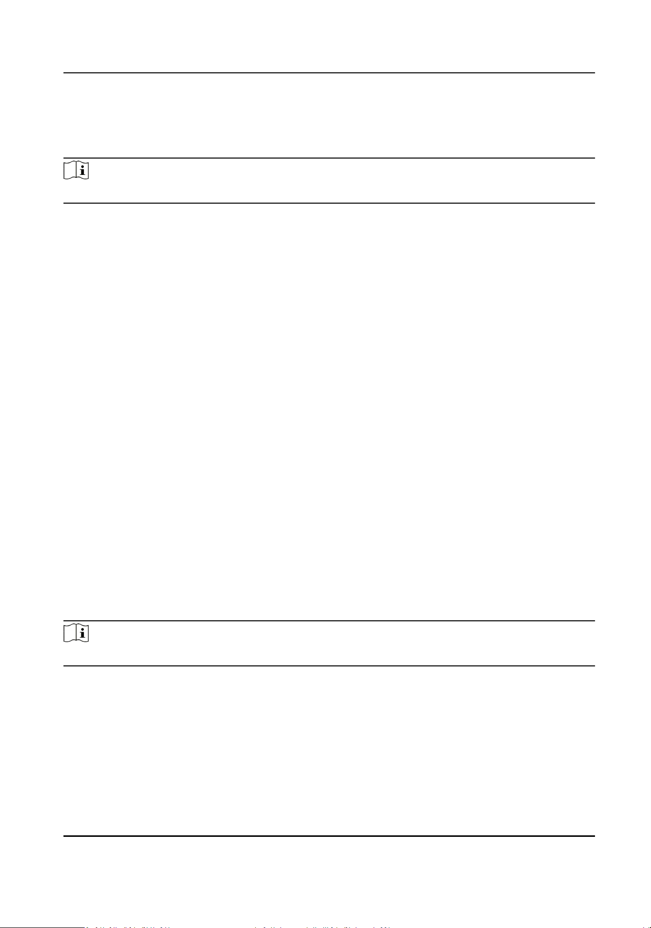
If you enable this funcon, you can save the picture captured by linked camera to the device.
Clear All Pictures in Device
Note
All pictures cannot be restored once they are deleted.
Clear Registered Face Pictures
All registered pictures in the device will be deleted.
Clear Captured Pictures
All captured pictures in the device will be deleted.
Set Card Authencaon Parameters
Set the card reading content when authencate via card on the device.
Go to Conguraon → Access Control → Card Authencaon Sengs .
Select a card authencaon mode and click Save.
Full Card No.
All card No. will be read.
Wiegand 26 (3 bytes)
The device will read card via Wiegand 26 protocol (read 3 bytes).
Wiegand 34 (4 bytes)
The device will read card via Wiegand 34 protocol (read 4 bytes).
8.5.20 Set Biometric Parameters
Set Basic Parameters
Click Conguraon → Smart → Smart .
Note
The funcons vary according to dierent models. Refers to the actual device for details.
DS-K1TA70 Series Face Recognion Terminal User Manual
97
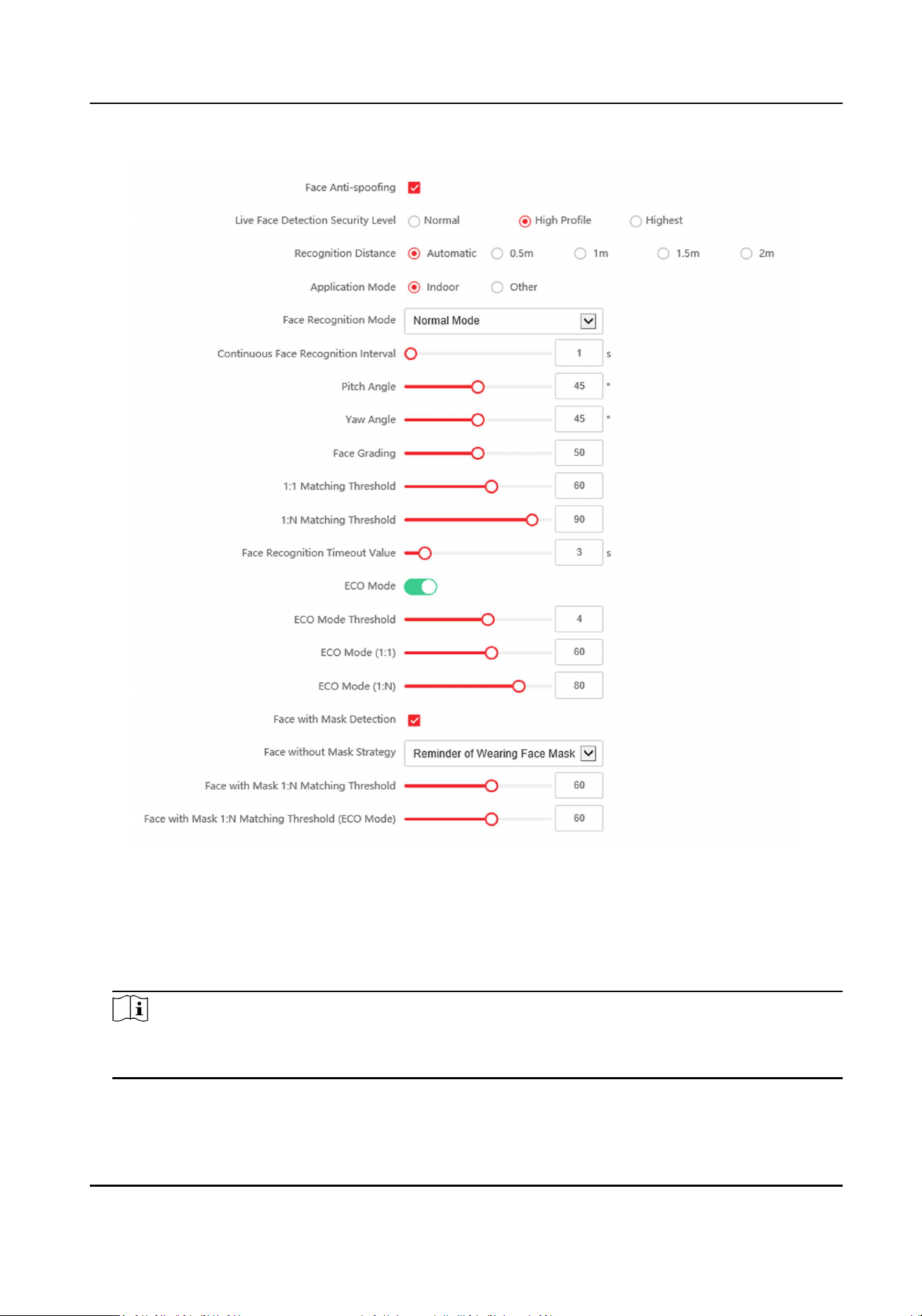
Figure 8-14 Smart Sengs Page
Click Save to save the sengs aer the conguraon.
Face An-spoong
Enable or disable the live face detecon funcon. If enabling the funcon, the device can
recognize whether the person is a live one or not.
Note
Biometric recognion products are not completely applicable to an-spoong environments. If
you require a higher security level, use mulple authencaon modes.
Live Face Detecon Security Level
DS-K1TA70 Series Face Recognion Terminal User Manual
98

Aer enabling the face an-spoong funcon, you can set the matching security level when
performing live face authencaon.
Recognion Distance
Select the distance between the authencang user and the device camera.
Applicaon Mode
Select either others or indoor according to actual environment.
Face Recognion Mode
Normal Mode
Recognize face via the camera normally.
Deep Mode
The device can recognize a much wider people range than the normal mode. This mode is
applicable to a more complicated environment.
Connuous Face Recognion Interval
Set the me interval between two connuous face recognions when authencang.
Pitch Angle
The maximum pitch angle when starng face authencaon.
Yaw Angle
The maximum yaw angle when starng face authencaon.
Face Grading
Set the face grading according to your needs.
1:1 Matching Threshold
Set the matching threshold when authencang via 1:1 matching mode. The larger the value,
the smaller the false accept rate and the larger the false rejecon rate.
1:N Matching Threshold
Set the matching threshold when authencang via 1:N matching mode. The larger the value,
the smaller the false accept rate and the larger the false rejecon rate.
Face Recognion Timeout Value
Set the meout value when face recognizing. If the face recognion me is longer than the
congured value, the system will pop up a prompt.
ECO Mode
Aer enabling the ECO mode, the device will use the IR camera to authencate faces in the low
light or dark environment. And you can set the ECO mode threshold, ECO mode (1:N), and ECO
mode (1:1).
ECO Mode (1:1)
Set the matching threshold when authencang via ECO mode 1:1 matching mode. The larger
the value, the smaller the false accept rate and the larger the false rejecon rate.
DS-K1TA70 Series Face Recognion Terminal User Manual
99

ECO Mode (1:N)
Set the matching threshold when authencang via ECO mode 1:N matching mode. The larger
the value, the smaller the false accept rate and the larger the false rejecon rate
Face with Mask Detecon
Aer enabling the face with mask detecon, the system will recognize the captured face with
mask picture. You can set face with mask1:N matching threshold, it's ECO mode, and the
strategy.
None
The device will detect the face with mask without prompt.
Prompt and Open
If the person do not wear a face mask when authencang, the device prompts a
nocaon and the door will open.
Prompt and Not Open Door
If the person do not wear a face mask when authencang, the device prompts a
nocaon and the door keeps closed.
Set Recognion Area
Click Conguraon → Smart → Area Conguraon .
Drag the yellow frame in the live video to adjust the recognion area. Only the face within the area
can be recognized by the system.
Click Save to save the sengs.
Click or to record videos or capture pictures.
8.5.21 Set Noce Publicaon
You can set the theme for the device.
Click Conguraon → Theme .
DS-K1TA70 Series Face Recognion Terminal User Manual
100
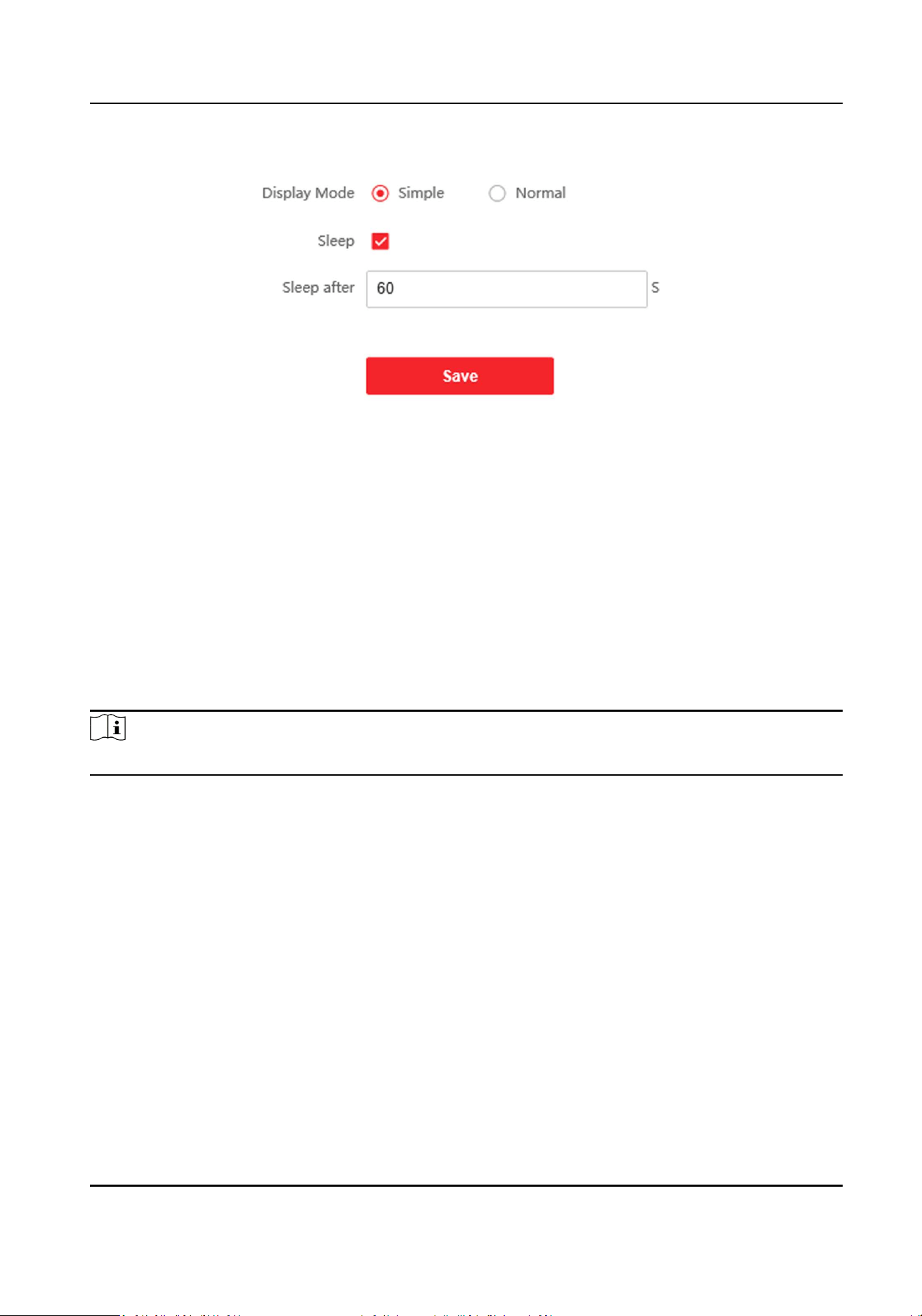
Figure 8-15 Theme Page
Display Mode
You can select display theme for device authencaon. You can select Display Mode as Simple
or Normal. When you select Simple, the informaon of name, ID, face picture will be not
displayed.
Sleep
Enable Sleep and the device will enter the sleep mode when no operaon within the congured
sleep me. Aer enabling Sleep, you need set the start me of display.
8.5.22 Temperature Measurement Sengs
Note
Temperature measurement is only supported by paral models.
Temperature Measurement Sengs
You can set the temperature measurement parameters, including temperature measurement only,
temperature unit, over-temperature threshold, temperature compensaon, door not open when
temperature is abnormal, etc.
Steps
1.
Click Conguraon → Temperature → Temperature Sengs .
DS-K1TA70 Series Face Recognion Terminal User Manual
101
Figure 8-16 Temperature Measurement Sengs
2.
Enable Temperature Measurement.
3.
Congure the temperature measurement parameters.
Enable Temperature Detecon
When enabling the funcon, the device will authencate the permissions and at the same
me take the temperature. When disabling the device, the device will authencate the
permissions only.
Over-Temperature Alarm Threshold (Max./Min.)
Edit the threshold according to actual situaon. If the detected temperature is higher or
lower than the congured parameters, an alarm will be triggered. By default, the value is
37.3°.
Temperature Compensaon
If the measured temperature is higher/lower than the actual object's temperature, you can
set the compensaon temperature here. Available range: -99 °C to 99 °C.
Door Not Open When Temperature is Abnormal
When enabling the funcon, the door will not open when the detected temperature is higher
or lower than the congured temperature threshold. By default, the funcon is enabled.
Temperature Measurement Only
DS-K1TA70 Series Face Recognion Terminal User Manual
102

When enabling the funcon, the device will not authencate the permissions, but only take
the temperature. When disabling the funcon, the device will authencate the permissions
and at the same me take the temperature.
Capture White Light Picture
Aer enabling Temperature Measurement Only, you can enable Capture White Light
Picture. Aer enabling this funcon, the device will capture white light picture.
Measure Area Sengs
Congure the temperature measurement area.
Unit
Select a temperature unit according to your preference.
4.
Click Save.
DS-K1TA70 Series Face Recognion Terminal User Manual
103
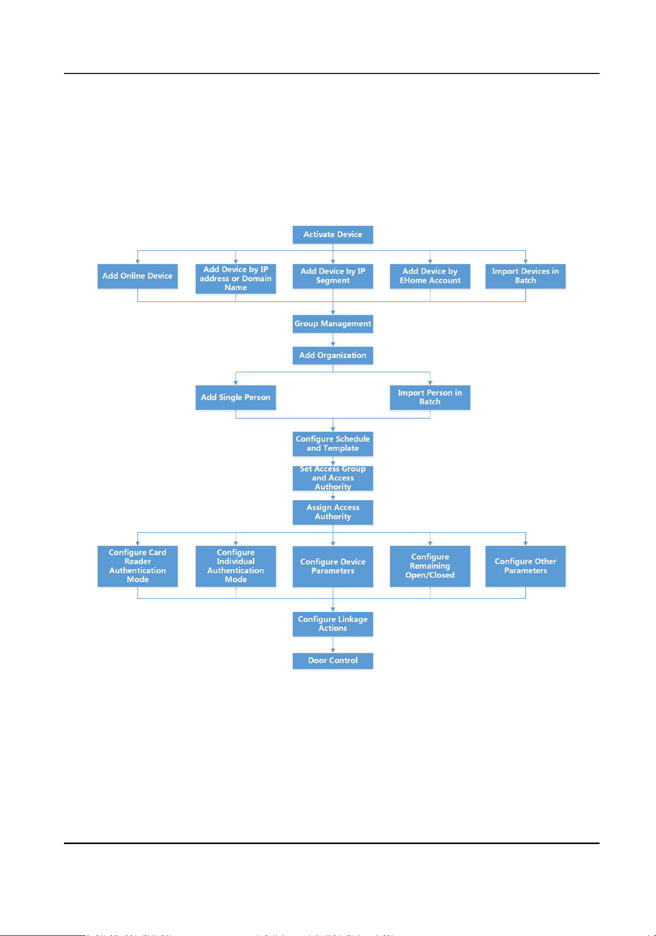
Chapter 9 Client Soware Conguraon
9.1 Conguraon Flow of Client Soware
Follow the ow diagram below to congure on the client soware.
Figure 9-1 Flow Diagram of Conguraon on Client Soware
9.2 Device Management
The client supports managing access control devices and video intercom devices.
DS-K1TA70 Series Face Recognion Terminal User Manual
104
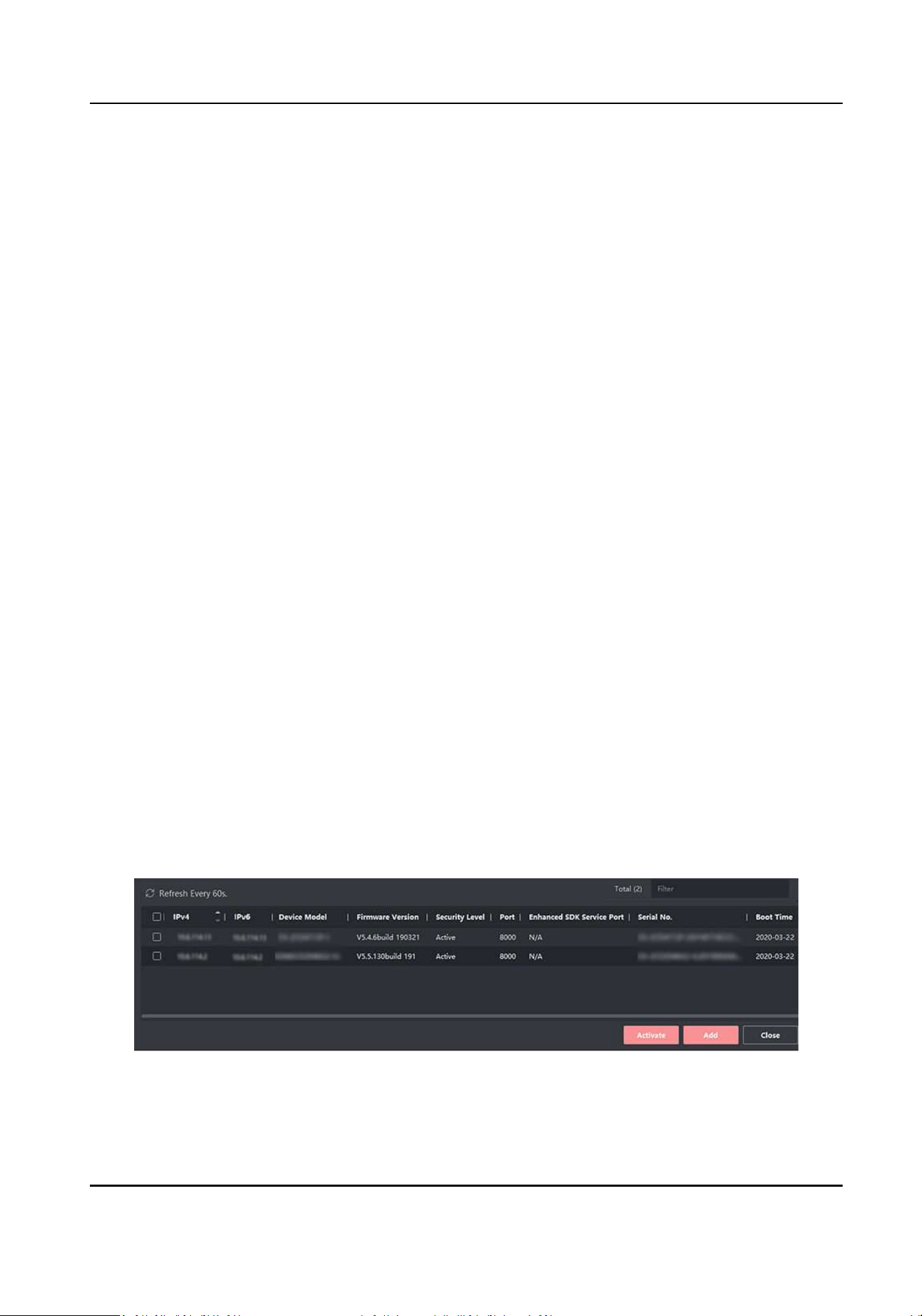
Example
You can control entrance & exit and manage aendance aer adding access control devices to the
client; you can perform video intercom with the indoor staons and door staons.
9.2.1 Add Device
The client provides three device adding modes including by IP/domain, IP segment, and ISUP
protocol. The client also supports imporng mulple devices in a batch when there are large
amount of devices to be added.
Add Online Device
The acve online devices in the same local subnet with the client soware will be displayed on the
Online Device area. You can click Refresh Every 60s to refresh the informaon of the online
devices.
Add Single or Mulple Online Devices
The client can detect online devices which are in the same network as the PC running the client.
You can select a detected online device displayed in the online device list and add it to the client.
For detected online devices sharing the same user name and password, you can add them to the
client in a batch.
Before You Start
●
The device(s) to be added are in the same network as the PC running the client.
●
The device(s) to be added have been acvated.
Steps
1.
Click Device Management → Device 。
2.
Click Online Device to show the online device area.
The searched online devices are displayed in the list.
Figure 9-2 Online Device
DS-K1TA70 Series Face Recognion Terminal User Manual
105
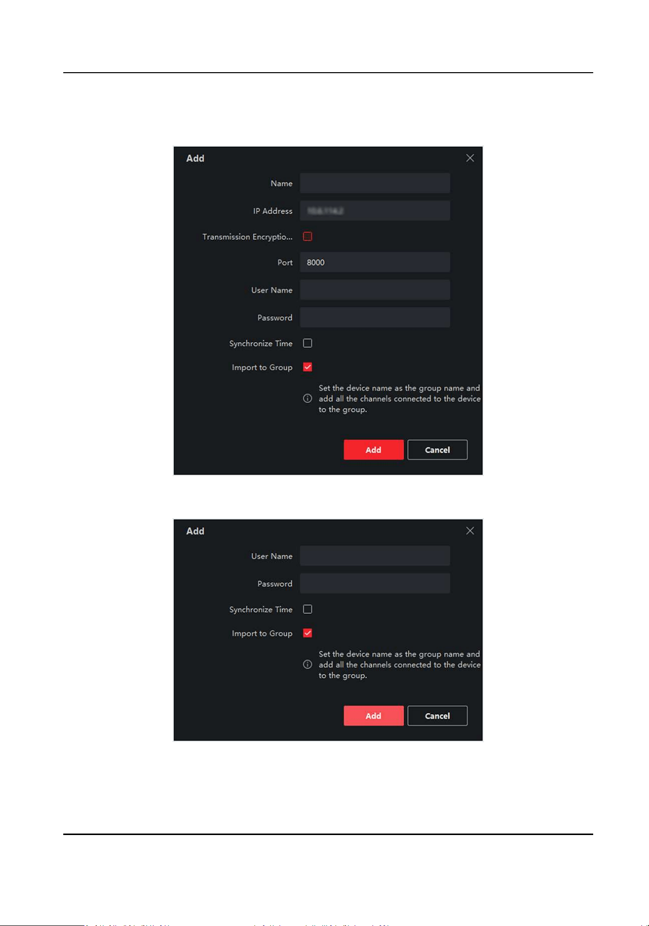
3.
In the Online Device area, check one or more online device(s), and click Add to open the device
adding window.
Figure 9-3 Add Single Online Device
Figure 9-4 Add Mulple Online Devices
4.
Enter the required informaon.
DS-K1TA70 Series Face Recognion Terminal User Manual
106
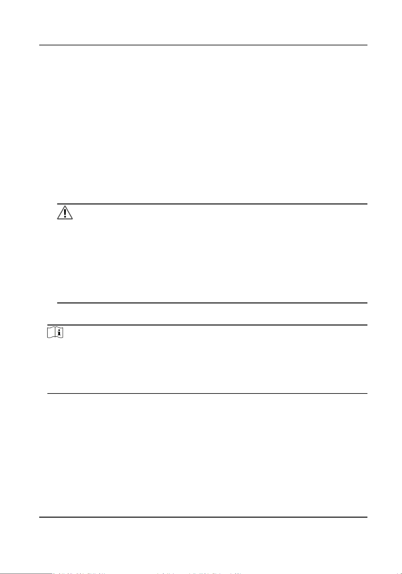
Name
Enter a descripve name for the device.
IP Address
Enter the device's IP address. The IP address of the device is obtained automacally in this
adding mode.
Port
You can customize the port number. The port number of the device is obtained automacally
in this adding mode.
User Name
By default, the user name is admin.
Password
Enter the device password.
Cauon
The password strength of the device can be automacally checked. We highly recommend
you change the password of your own choosing (using a minimum of 8 characters, including
at least three kinds of following categories: upper case leers, lower case leers, numbers,
and special characters) in order to increase the security of your product. And we recommend
you change your password regularly, especially in the high security system, changing the
password monthly or weekly can beer protect your product.
Proper conguraon of all passwords and other security sengs is the responsibility of the
installer and/or end-user.
5.
Oponal: Check Transmission Encrypon (TLS) to enable transmission encrypon using TLS
(Transport Layer Security) protocol for security purpose.
Note
●
This funcon should be supported by the device.
●
If you have enabled Cercate Vericaon, you should click Open Cercate Directory to
open the default folder, and copy the cercate le exported from the device to this default
directory to strengthen the security. See for details about enabling cercate vericaon.
●
You can log into the device to get the cercate le by web browser.
6.
Check Synchronize Time to synchronize the device me with the PC running the client aer
adding the device to the client.
7.
Oponal: Check Import to Group to create a group by the device name, and import all the
channels of the device to this group.
Example
For access control device, its access points, alarm inputs/outputs, and encoding channels (if
exist) will be imported to this group.
8.
Click Add.
DS-K1TA70 Series Face Recognion Terminal User Manual
107
Add Mulple Detected Online Devices
For detected online devices sharing the same user name and password, you can add them to the
client in a batch.
Before You Start
Make sure the to-be-added devices are online.
Steps
1.
Enter the Device Management module.
2.
Click Device tab on the top of the right panel.
3.
Click Online Device to show the online device area at the boom of the page.
The searched online devices are displayed in the list.
4.
Select mulple devices.
Note
For the inacve device, you need to create the password for it before you can add the device
properly. For details, refer to .
5.
Click Add to open the device adding window.
6.
Enter the required informaon.
User Name
By default, the user name is admin.
Password
Enter the device password.
Cauon
The password strength of the device can be automacally checked. We highly recommend
you change the password of your own choosing (using a minimum of 8 characters, including
at least three kinds of following categories: upper case leers, lower case leers, numbers,
and special characters) in order to increase the security of your product. And we recommend
you change your password regularly, especially in the high security system, changing the
password monthly or weekly can beer protect your product.
Proper conguraon of all passwords and other security sengs is the responsibility of the
installer and/or end-user.
7.
Oponal: Check Synchronize Time to synchronize the device me with the PC running the client
aer adding the device to the client.
8.
Oponal: Check Import to Group to create a group by the device name, and import all the
channels of the device to this group.
Example
For access control device, its access points, alarm inputs/outputs, and encoding channels (if
exist) will be imported to this group.
DS-K1TA70 Series Face Recognion Terminal User Manual
108
9.
Click Add to add the devices.
Add Device by IP Address or Domain Name
If you know the IP address or domain name of the device to add, you can add devices to the client
by specifying the IP address (or domain name), user name, password, etc.
Steps
1.
Enter Device Management module.
2.
Click Device tab on the top of the right panel.
The added devices are displayed on the right panel.
3.
Click Add to open the Add window, and then select IP/Domain as the adding mode.
4.
Enter the required informaon.
Name
Create a descripve name for the device. For example, you can use a nickname that can show
the locaon or feature of the device.
Address
The IP address or domain name of the device.
Port
The devices to add share the same port number. The default value is 8000.
User Name
Enter the device user name. By default, the user name is admin.
Password
Enter the device password.
Cauon
The password strength of the device can be automacally checked. We highly recommend
you change the password of your own choosing (using a minimum of 8 characters, including
at least three kinds of following categories: upper case leers, lower case leers, numbers,
and special characters) in order to increase the security of your product. And we recommend
you change your password regularly, especially in the high security system, changing the
password monthly or weekly can beer protect your product.
Proper conguraon of all passwords and other security sengs is the responsibility of the
installer and/or end-user.
5.
Oponal: Check Transmission Encrypon (TLS) to enable transmission encrypon using TLS
(Transport Layer Security) protocol for security purpose.
DS-K1TA70 Series Face Recognion Terminal User Manual
109

Note
●
This funcon should be supported by the device.
●
If you have enabled Cercate Vericaon, you should click Open Cercate Directory to
open the default folder, and copy the cercate le exported from the device to this default
directory to strengthen the security. See for details about enabling cercate vericaon.
●
You can log into the device to get the cercate le by web browser.
6.
Check Synchronize Time to synchronize the device me with the PC running the client aer
adding the device to the client.
7.
Oponal: Check Import to Group to create a group by the device name, and import all the
channels of the device to this group.
Example
For access control device, its access points, alarm inputs/outputs, and encoding channels (if
exist) will be imported to this group.
8.
Finish adding the device.
-
Click Add to add the device and back to the device list page.
-
Click Add and New to save the sengs and connue to add other device.
Add Devices by IP Segment
If the devices share the same port No., user name and password, and their IP addresses ranges in
the same IP segment, you can add them to the client by specifying the start IP address and the end
IP address, port No., user name, password, etc of the devices.
Steps
1.
Enter the Device Management module.
2.
Click Device tab on the top of the right panel.
The added devices are displayed on the right panel.
3.
Click Add to open the Add window.
4.
Select IP Segment as the adding mode.
5.
Enter the required informaon.
Start IP
Enter a start IP address.
End IP
Enter an end IP address in the same network segment with the start IP.
Port
Enter the device port No. The default value is 8000.
User Name
By default, the user name is admin.
Password
DS-K1TA70 Series Face Recognion Terminal User Manual
110
Enter the device password.
Cauon
The password strength of the device can be automacally checked. We highly recommend
you change the password of your own choosing (using a minimum of 8 characters, including
at least three kinds of following categories: upper case leers, lower case leers, numbers,
and special characters) in order to increase the security of your product. And we recommend
you change your password regularly, especially in the high security system, changing the
password monthly or weekly can beer protect your product.
Proper conguraon of all passwords and other security sengs is the responsibility of the
installer and/or end-user.
6.
Oponal: Check Transmission Encrypon (TLS) to enable transmission encrypon using TLS
(Transport Layer Security) protocol for security purpose .
Note
●
This funcon should be supported by the device.
●
If you have enabled Cercate Vericaon, you should click Open Cercate Folder to open
the default folder, and copy the cercate le exported from the device to this default
directory to strengthen the security. See for details about enabling cercate vericaon.
●
You can log into the device to get the cercate le by web browser.
7.
Check Synchronize Time to synchronize the device me with the PC running the client aer
adding the device to the client.
8.
Oponal: Check Import to Group to create a group by the device name, and import all the
channels of the device to the group.
9.
Finish adding the device.
-
Click Add to add the device and back to the device list page.
-
Click Add and New to save the sengs and connue to add other device.
Add Device by ISUP Account
For access control devices supports ISUP 5.0 protocol, you can add them to the client by ISUP
protocol aer entering device ID and key, if you have congured their server addresses, port No.,
and device IDs.
Before You Start
Make sure the devices have connected to the network properly.
Steps
1.
Enter Device Management module.
The added devices are displayed on the right panel.
2.
Click Add to open the Add window.
3.
Select ISUP as the adding mode.
4.
Enter the required informaon.
DS-K1TA70 Series Face Recognion Terminal User Manual
111
Device Account
Enter the account name registered on ISUP protocol.
ISUP Key
For ISUP 5.0 devices, enter the ISUP key if you have set it when conguring network center
parameter for the device.
Note
This funcon should be supported by the device.
5.
Oponal: Check Synchronize Time to synchronize the device me with the PC running the client
aer adding the device to the client.
6.
Oponal: Check Import to Group to create a group by the device name, and import all the
channels of the device to the group.
7.
Finish adding the device.
-
Click Add to add the device and go back to the device list.
-
Click Add and New to save the sengs and connue to add other device.
8.
Oponal: Perform the following operaon(s).
Device Status Click
on Operaon column to view device status.
Edit Device
Informaon
Click
on Operaon column to edit the device informaon, such as
device name, device account, and ISUP key.
Check Online User Click
on Operaon column to check the online users who access the
device, such as user name, user type, user's IP address, and login me.
Refresh Click
on Operaon column to get the latest device informaon.
Delete Device Select one or mulple devices and click Delete to delete the selected
device(s) from the client.
Import Devices in a Batch
You can add mulple devices to the client in a batch by entering the device parameters in a pre-
dened CSV le.
Steps
1.
Enter the Device Management module.
2.
Click Device tab on the top of the right panel.
3.
Click Add to open the Add window, and then select Batch Import as the adding mode.
4.
Click Export Template and then save the pre-dened template (CSV le) on your PC.
5.
Open the exported template le and enter the required informaon of the devices to be added
on the corresponding column.
Note
For detailed descripon of the required elds, refer to the introducons in the template.
DS-K1TA70 Series Face Recognion Terminal User Manual
112
Adding Mode
Enter 0 or 1 or 2.
Address
Edit the address of the device.
Port
Enter the device port number. The default port number is 8000.
User Name
Enter the device user name. By default, the user name is admin.
Password
Enter the device password.
Cauon
The password strength of the device can be automacally checked. We highly recommend
you change the password of your own choosing (using a minimum of 8 characters, including
at least three kinds of following categories: upper case leers, lower case leers, numbers,
and special characters) in order to increase the security of your product. And we recommend
you change your password regularly, especially in the high security system, changing the
password monthly or weekly can beer protect your product.
Proper conguraon of all passwords and other security sengs is the responsibility of the
installer and/or end-user.
Import to Group
Enter 1 to create a group by the device name. All the channels of the device will be imported
to the corresponding group by default. Enter 0 to disable this funcon.
6.
Click and select the template le.
7.
Click Add to import the devices.
9.2.2 Reset Device Password
If you forgot the password of the detected online devices, you can reset the device password via
the client.
Steps
1.
Enter Device Management page.
2.
Click Online Device to show the online device area.
All the online devices sharing the same subnet will be displayed in the list.
3.
Select the device from the list and click on the Operaon column.
4.
Reset the device password.
-
Click Generate to pop up the QR Code window and click Download to save the QR code to
your PC. You can also take a photo of the QR code to save it to your phone. Send the picture
to our technical support.
DS-K1TA70 Series Face Recognion Terminal User Manual
113
Note
For the following operaons for reseng the password, contact our technical support.
Cauon
The password strength of the device can be automacally checked. We highly recommend you
change the password of your own choosing (using a minimum of 8 characters, including at least
three kinds of following categories: upper case leers, lower case leers, numbers, and special
characters) in order to increase the security of your product. And we recommend you change
your password regularly, especially in the high security system, changing the password monthly
or weekly can beer protect your product.
Proper conguraon of all passwords and other security sengs is the responsibility of the
installer and/or end-user.
9.3 Group Management
The client provides groups to manage the added resources in dierent groups. You can group the
resources into dierent groups according to the resources' locaons.
Example
For example, on the 1st oor, there mounted 16 doors, 64 alarm inputs, and 16 alarm outputs. You
can organize these resources into one group (named 1st Floor) for convenient management. You
can control door status, and do some other operaons of the devices aer managing the resources
by groups.
9.3.1 Add Group
You can add group to organize the added device for convenient management.
Steps
1.
Enter the Device Management module.
2.
Click Device Management → Group to enter the group management page.
3.
Create a group.
-
Click Add Group and enter a group name as you want.
-
Click Create Group by Device Name and select an added device to create a new group by the
name of the selected device.
Note
The resources (such as alarm inputs/outputs, access points, etc.) of this device will be
imported to the group by default.
DS-K1TA70 Series Face Recognion Terminal User Manual
114
9.3.2 Import Resources to Group
You can import the device resources (such as alarm inputs/outputs, access points, etc.) to the
added group in a batch.
Before You Start
Add a group for managing devices. Refer to Add Group .
Steps
1.
Enter the Device Management module.
2.
Click Device Management → Group to enter the group management page.
3.
Select a group from the group list and select the resource type as Access Point, Alarm Input,
Alarm Output, etc.
4.
Click Import.
5.
Select the thumbnails/names of the resources in the thumbnail/list view.
Note
You can click or to switch the resource display mode to thumbnail view or to list view.
6.
Click Import to import the selected resources to the group.
9.3.3 Edit Resource Parameters
Aer imporng the resources to the group, you can edit the resource parameters. For access point,
you can edit the access point name. For alarm input, you can edit the alarm input name. Here we
take access point as an example.
Before You Start
Import the resources to group.
Steps
1.
Enter the Device Management module.
2.
Click Device Management → Group to enter the group management page.
All the added groups are displayed on the le.
3.
Select a group on the group list and click Access Point.
The access points imported to the group will display.
4.
Click
in the Operaon column to open the Edit Resource window.
5.
Edit the resource name.
6.
Click OK to save the new sengs.
9.3.4 Remove Resources from Group
You can remove the added resources from the group.
DS-K1TA70 Series Face Recognion Terminal User Manual
115
Steps
1.
Enter the Device Management module.
2.
Click Device Management → Group to enter the group management page.
All the added groups are displayed on the le.
3.
Click a group to show the resources added to this group.
4.
Select the resource(s) and click Delete to remove the resource(s) from the group.
9.4 Person Management
You can add person informaon to the system for further operaons such as access control, video
intercom, me and aendance, etc. You can manage the added persons such as issuing cards to
them in a batch, imporng and exporng person informaon in a batch, etc.
9.4.1 Add Organizaon
You can add an organizaon and import person informaon to the organizaon for eecve
management of the persons. You can also add a surbodinate organizaon for the added one.
Steps
1.
Enter Person module.
2.
Select a parent organizaon in the le column and click Add in the upper-le corner to add an
organizaon.
3.
Create a name for the added organizaon.
Note
Up to 10 levels of organizaons can be added.
4.
Oponal: Perform the following operaon(s).
Edit Organizaon Hover the mouse on an added organizaon and click
to edit its name.
Delete
Organizaon
Hover the mouse on an added organizaon and click
to delete it.
Note
●
The lower-level organizaons will be deleted as well if you delete an
organizaon.
●
Make sure there is no person added under the organizaon, or the
organizaon cannot be deleted.
Show Persons in
Sub Organizaon
Check Show Persons in Sub Organizaon and select an organizaon to
show persons in its sub organizaons.
DS-K1TA70 Series Face Recognion Terminal User Manual
116
9.4.2 Congure Basic Informaon
You can add person to the client one by one and congure the person's basic informaon such as
name, email, phone number, etc.
Steps
1.
Enter Person module.
Note
For the rst me you enter Person module, a window pops up, and you can set the rules to
generate person ID (leers and numbers supported) when adding person. When geng person
informaon from device, if there are no person IDs, the person IDs will be generated according
to the rule.
2.
Select an organizaon in the organizaon list to add the person.
3.
Click Add to open the adding person window.
The Person ID will be generated automacally.
4.
Enter the basic informaon including person name, telephone number, email address, validity
period, etc.
5.
Conrm to add the person.
-
Click Add to add the person and close the Add Person window.
-
Click Add and New to add the person and connue to add other persons.
9.4.3 Issue a Card to One Person
When adding person, you can issue a card with a unique card number to the person as a
credenal. Aer issued, the person can access the doors which he/she is authorized to access by
swiping the card on the card reader.
Steps
Note
Up to ve cards can be issued to one person.
1.
Enter Person module.
2.
Select an organizaon in the organizaon list to add the person and click Add.
Note
Enter the person's basic informaon rst. For details about conguring person's basic
informaon, refer to Congure Basic Informaon .
3.
In the Credenal → Card panel, click +.
4.
Enter the card number.
-
Enter the card number manually.
DS-K1TA70 Series Face Recognion Terminal User Manual
117
-
Place the card on the card enrollment staon or card reader and click Read to get the card
number. The card number will display in the Card No. eld automacally.
Note
You need to click Sengs to set the card issuing mode and related parameters rst. For
details, refer to Set Card Issuing Parameters .
5.
Select the card type according to actual needs.
Normal Card
The card is used for opening doors for normal usage.
Duress Card
When the person is under duress, he/she can swipe the duress card to open the door. The
door will be unlocked and the client will receive a duress event to nofy the security
personnel.
Patrol Card
This card is used for the inspecon sta to check the their aendance of inspecon. By
swiping the card on the specied card reader, the person is marked as on duty of inspecon
at that me.
Dismiss Card
By swiping the card on the card reader, it can stop the buzzing of the card reader.
6.
Click Add.
The card will be issued to the person.
7.
Conrm to add the person.
-
Click Add to add the person and close the Add Person window.
-
Click Add and New to add the person and connue to add other persons.
9.4.4 Upload a Face Photo from Local PC
When adding person, you can upload a face photo stored in local PC to the client as the person's
prole.
Steps
1.
Enter Person module.
2.
Select an organizaon in the organizaon list to add the person and click Add.
Note
Enter the person's basic informaon rst. For details about conguring person's basic
informaon, refer to Congure Basic Informaon .
3.
Click Add Face in the Basic Informaon panel.
4.
Select Upload.
5.
Select a picture from the PC running the client.
DS-K1TA70 Series Face Recognion Terminal User Manual
118
Note
The picture should be in JPG or JPEG format and smaller than 200 KB.
6.
Oponal: Enable Verify by Device to check whether the facial recognion device managed in
the client can recognize the face in the photo.
Note
This funcon is hidden or shown according to the device capacity.
7.
Conrm to add the person.
-
Click Add to add the person and close the Add Person window.
-
Click Add and New to add the person and connue to add other persons .
9.4.5 Take a Photo via Client
When adding a person, you can take a photo of the her/him via the client and set this photo as the
person's prole.
Before You Start
Make sure PC running the client has a camera or you have connected other USB camera to the PC.
Steps
1.
Enter Person module.
2.
Select an organizaon in the organizaon list to add the person and click Add to enter Add
Person window.
Note
Enter the person's basic informaon rst. For details, refer to Congure Basic Informaon .
3.
Click Add Face in the Basic Informaon area.
4.
Select Take Photo to enter Take Photo window.
5.
Oponal: Enable Verify by Device to check whether the captured face photo can meet the
uploading requirements.
Note
This funcon is hidden or shown according to the device capacity.
6.
Take a photo.
1) Face to the camera and make sure your face is in the middle of the collecng window.
2) Click to capture a face photo.
3) Oponal: Click to capture again.
4) Click OK to save the captured photo.
DS-K1TA70 Series Face Recognion Terminal User Manual
119
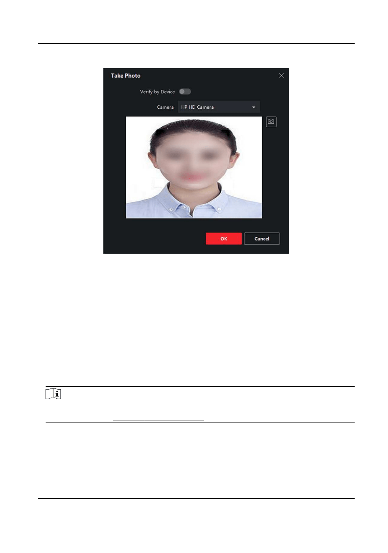
Figure 9-5 Take a Photo via Client
7.
Conrm to add the person.
-
Click Add to add the person and close the Add Person window.
-
Click Add and New to add the person and connue to add other persons.
9.4.6 Collect Face via Access Control Device
When adding person, you can collect the person's face via access control device added to the client
which supports facial recognion funcon.
Steps
1.
Enter Person module.
2.
Select an organizaon in the organizaon list to add the person and click Add.
Note
Enter the person's basic informaon rst. For details about conguring person's basic
informaon, refer to Congure Basic Informaon .
3.
Click Add Face in the Basic Informaon panel.
4.
Select Remote Collecon.
5.
Select an added access control device or the enrollment staon from the drop-down list.
DS-K1TA70 Series Face Recognion Terminal User Manual
120
Note
If you select the enrollment staon, you should click Login to set related parameters of the
device including IP address, port No., user name, and password. Also, you can check Face An-
Spoong and select the liveness level as Low, Medium, or High.
Face An-Spoong
If you check this funcon, then the device can detect whether the face to be collected is an
authenc one.
6.
Collect face.
1) Face to the camera of the selected access control device and make sure your face is in the
middle of the collecng window.
2) Click to capture a photo.
3) Click OK to save the captured photo.
7.
Conrm to add the person.
-
Click Add to add the person and close the Add Person window.
-
Click Add and New to add the person and connue to add other persons .
9.4.7 Congure Access Control Informaon
When adding a person, you can set her/his access control informaon, such as binding an access
control group with the person, conguring PIN code, seng the person as a visitor, a blocklist
person, or a super user, etc.
Steps
1.
Enter Person module.
2.
Select an organizaon in the organizaon list to add the person and click Add.
3.
In the Access Control area, click
to select access group(s) for the person.
Note
For details, refer to Set Access Group to Assign Access Authorizaon to Persons .
DS-K1TA70 Series Face Recognion Terminal User Manual
121
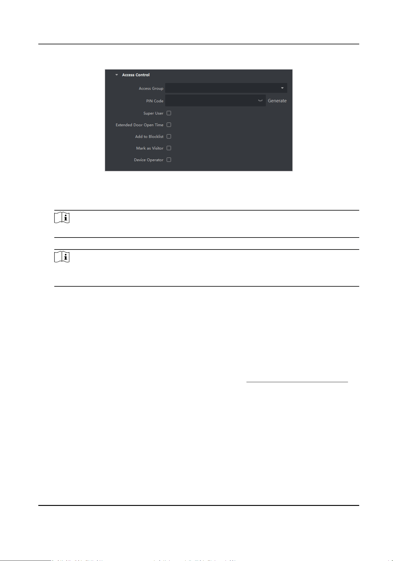
Figure 9-6 Congure Access Control Informaon
4.
Set a unique PIN code for the person which can be used for access authencaon.
-
Manually enter a PIN code containing 4 to 8 digits.
Note
Persons' PIN codes cannot be repeated.
-
Click Generate to randomly generate an unrepeated PIN code of 6 digits.
Note
If there are repeated PIN codes, a prompt will pop up on the client. The admin can generate a
new PIN code to replace the repeated PIN code and nofy related persons.
5.
Check the person's operaon permissions.
Super User
If the person is set as a super user, he/she will have authorizaon to access all the doors/
oors and will be exempted from remaining closed restricons, all an-passback rules, and
rst person authorizaon.
Extended Door Open Time
Use this funcon for persons with reduced mobility. When accessing the door, the person will
have more me than others to pass through doors.
For details about seng the door's open duraon, refer to Congure Parameters for Door .
Add to Blocklist
Add the person to the blocklist and when the person tries to access doors/oors, an event
will be triggered and sent to the client to nofy the security personnel.
Mark as Visitor
If the person is a visitor, you should set the her/his valid mes for visit.
DS-K1TA70 Series Face Recognion Terminal User Manual
122
Note
The valid mes for visit is between 1 and 100. You can also check No Limit, then there are no
limited mes for the visitor to access doors/oors.
Device Operator
For person with device operator role, he/she is authorized to operate on the access control
devices.
Note
The Super User, Extended Door Open Time, Add to Blocklist, and Mark as Visitor funcons
cannot be enabled concurrently. For example, if one person is set as super user, you cannot
enable extended door open me for her/him, add her/him to the blocklist, or set her/him as
visitor.
6.
Conrm to add the person.
-
Click Add to add the person and close the Add Person window.
-
Click Add and New to add the person and connue to add other persons.
9.4.8 Customize Person Informaon
You can customize the person properes which are not pre-dened in the client according to actual
needs, e.g., place of birth. Aer customizing, when add a person, you can enter the custom
informaon to make the person informaon complete.
Steps
1.
Enter Person module.
2.
Set the elds of custom informaon.
1) Click Custom Property.
2) Click Add to add a new property.
3) Enter the property name.
4) Click OK.
3.
Set the custom informaon when adding a person.
1) Select an organizaon in the organizaon list to add the person and click Add.
Note
Enter the person's basic informaon rst. For details about conguring person's basic
informaon, refer to Congure Basic Informaon .
2) In the Custom Informaon panel, enter the person informaon.
3) Click Add to add the person and close the Add Person window, or click Add and New to add
the person and connue to add other persons.
DS-K1TA70 Series Face Recognion Terminal User Manual
123
9.4.9 Congure Resident Informaon
If the person is resident, for video intercom purpose, you need to set the room number for
her/him and bind an indoor staon. Aer bound, you can call this person by calling the indoor
staon and perform video intercom with her/him.
Steps
1.
Enter Person module.
2.
Select an organizaon in the organizaon list to add the person and click Add.
Note
Enter the person's basic informaon rst. For details about conguring person's basic
informaon, refer to Congure Basic Informaon .
3.
In the Resident Informaon panel, select the indoor staon to bind it to the person.
Note
If you select Analog Indoor Staon, the Door Staon eld will display and you are required to
select the door staon to communicate with the analog indoor staon.
4.
Enter the oor No. and room No. of the person.
5.
Conrm to add the person.
-
Click Add to add the person and close the Add Person window.
-
Click Add and New to add the person and connue to add other persons.
9.4.10 Congure Addional Informaon
When adding person, you can congure the addional informaon for the person, such as person's
identy type, identy No., country, etc., according to actual needs.
Steps
1.
Enter Person module.
2.
Select an organizaon in the organizaon list to add the person and click Add.
Note
Enter the person's basic informaon rst. For details about conguring person's basic
informaon, refer to Congure Basic Informaon .
3.
In the Addional Informaon panel, enter the addional informaon of the person, including
person's ID type, ID No., job tle, etc., according to actual needs.
4.
Conrm to add the person.
-
Click Add to add the person and close the Add Person window.
-
Click Add and New to add the person and connue to add other persons .
DS-K1TA70 Series Face Recognion Terminal User Manual
124
9.4.11 Import and Export Person Idenfy Informaon
You can import the informaon and pictures of mulple persons to the client soware in a batch.
Meanwhile, you can also export the person informaon and pictures and save them in your PC.
9.4.12 Import Person Informaon
You can enter the informaon of mulple persons in a predened template (CSV/Excel le) to
import the informaon to the client in a batch.
Steps
1.
Enter the Person module.
2.
Select an added organizaon in the list, or click Add in the upper-le corner to add an
organizaon and then select it.
3.
Click Import to open the Import panel.
4.
Select Person Informaon as the imporng mode.
5.
Click Download Template for Imporng Person to download the template.
6.
Enter the person informaon in the downloaded template.
Note
●
If the person has mulple cards, separate the card No. with semicolon.
●
Items with asterisk are required.
●
By default, the Hire Date is the current date.
7.
Click to select the CSV/Excel le with person informaon from local PC.
8.
Click Import to start imporng.
Note
●
If a person No. already exists in the client's database, delete the exisng informaon before
imporng.
●
You can import informaon of no more than 2,000 persons.
9.4.13 Import Person Pictures
Aer imporng face pictures for the added persons to the client, the persons in the pictures can be
idened by an added face recognion terminal. You can either import person pictures one by
one, or import mulple pictures at a me according to your need.
Before You Start
Be sure to have imported person informaon to the client beforehand.
Steps
1.
Enter the Person module.
DS-K1TA70 Series Face Recognion Terminal User Manual
125
2.
Select an added organizaon in the list, or click Add in the upper-le corner to add an
organizaon and then select it.
3.
Click Import to open the Import panel and check Face.
4.
Oponal: Enable Verify by Device to check whether face recognion device managed in the
client can recognize the face in the photo.
5.
Click to select a face picture le.
Note
●
The (folder of) face pictures should be in ZIP format.
●
Each picture le should be in JPG format and should be no larger than 200 KB.
●
Each picture le should be named as "Person ID_Name". The Person ID should be the same
with that of the imported person informaon.
6.
Click Import to start imporng.
The imporng progress and result will be displayed.
9.4.14 Export Person Informaon
You can export the added persons' informaon to local PC as a CSV/Excel le.
Before You Start
Make sure you have added persons to an organizaon.
Steps
1.
Enter the Person module.
2.
Oponal: Select an organizaon in the list.
Note
All persons' informaon will be exported if you do not select any organizaon.
3.
Click Export to open the Export panel.
4.
Check Person Informaon as the content to export.
5.
Check desired items to export.
6.
Click Export to save the exported le in CSV/Excel le on your PC.
9.4.15 Export Person Pictures
You can export face picture le of the added persons and save in your PC.
Before You Start
Make sure you have added persons and their face pictures to an organizaon.
Steps
1.
Enter the Person module.
2.
Oponal: Select an organizaon in the list.
DS-K1TA70 Series Face Recognion Terminal User Manual
126
Note
All persons' face pictures will be exported if you do not select any organizaon.
3.
Click Export to open the Export panel and check Face as the content to export.
4.
Click Export to start exporng.
Note
●
The exported le is in ZIP format.
●
The exported face picture is named as "Person ID_Name_0" ("0" is for a full-frontal face).
9.4.16 Delete Registered Pictures
You can delete face picture le of the added persons automacally.
Before You Start
Make sure you have saved the structure data.
Steps
1.
Enter the Person module.
2.
Oponal: Select a person item in the list.
3.
Click Delete Registered Picture to delete the registered picture.
9.4.17 Get Person Informaon from Access Control Device
If the added access control device has been congured with person informaon (including person
details and issued card informaon), you can get the person informaon from the device and
import them to the client for further operaons.
Steps
Note
●
If the person name stored in the device is empty, the person name will be lled with the issued
card No. aer imporng to the client.
●
If the card number or person ID (employee ID) stored on the device already exists in the client
database, the person with this card number or person ID will not be imported to the client.
1.
Enter Person module.
2.
Select an organizaon to import the persons.
3.
Click Get from Device.
4.
Select an added access control device or the enrollment staon from the drop-down list.
DS-K1TA70 Series Face Recognion Terminal User Manual
127

Note
If you select the enrollment staon, you should click Login, and set IP address, port No., user
name and password of the device.
5.
Click Import to start imporng the person informaon to the client.
Note
Up to 2,000 persons and 5,000 cards can be imported.
The person informaon, including person details, and the linked cards (if congured), will be
imported to the selected organizaon.
9.4.18 Move Persons to Another Organizaon
You can move the added persons to another organizaon if you need.
Before You Start
●
Make sure you have added at least two organizaons.
●
Make sure you have imported person informaon.
Steps
1.
Enter Person module.
2.
Select an organizaon in the le panel.
The persons under the organizaon will be displayed in the right panel.
3.
Select the person to move.
4.
Click Change Organizaon.
5.
Select the organizaon to move persons to.
6.
Click OK.
9.4.19 Issue Cards to Persons in Batch
The client provides a convenient way to issue cards to mulple persons in a batch.
Steps
1.
Enter Person module.
2.
Click Batch Issue Cards.
All the added persons with no card issued will be displayed in the right panel.
3.
Oponal: Enter key words (name or person ID) in the input box to lter the person(s) that need
issuing cards.
4.
Oponal: Click Sengs to set the card issuing parameters. For details, refer to Issue a Card by
Local Mode.
5.
Click Inialize to inialize the card enrollment staon or card reader to make it ready for issuing
cards.
6.
Click the Card No. column and enter the card number.
DS-K1TA70 Series Face Recognion Terminal User Manual
128

-
Place the card on the card enrollment staon.
-
Swipe the card on the card reader.
-
Manually enter the card number and press the Enter key.
The person(s) in the list will be issued with card(s).
9.4.20 Report Card Loss
If the person lost his/her card, you can report the card loss so that the card's related access
authorizaon will be inacve.
Steps
1.
Enter Person module.
2.
Select the person you want to report card loss for and click Edit to open the Edit Person window.
3.
In the Credenal → Card panel, click
on the added card to set this card as lost card.
Aer reporng card loss, the access authorizaon of this card will be invalid and inacve. Other
person who gets this card cannot access the doors by swiping this lost card.
4.
Oponal: If the lost card is found, you can click to cancel the loss.
Aer cancelling card loss, the access authorizaon of the person will be valid and acve.
5.
If the lost card is added in one access group and the access group is applied to the device
already, aer reporng card loss or cancelling card loss, a window will pop up to nofy you to
apply the changes to the device. Aer applying to device, these changes can take eect on the
device.
9.4.21 Set Card Issuing Parameters
The client provides two modes for reading a card's number: via card enrollment staon or via the
card reader of the access control device. If a card enrollment staon is available, connect it to the
PC running the client by USB interface or COM, and place the card on the card enrollment to read
the card number. If not, you can also swipe the card on the card reader of the added access control
device to get the card number. As a result, before issuing a card to one person, you need to set the
card issuing parameters including the issuing mode and related parameters.
When adding a card to one person, click Sengs to open the Card Issuing Sengs window.
Local Mode: Issue Card by Card Enrollment Staon
Connect a card enrollment staon to the PC running the client. You can place the card on the card
enrollment staon to get the card number.
Card Enrollment Staon
Select the model of the connected card enrollment staon
DS-K1TA70 Series Face Recognion Terminal User Manual
129
Note
Currently, the supported card enrollment staon models include DS-K1F100-D8, DS-K1F100-M,
DS-K1F100-D8E, and DS-K1F180-D8E.
Card Type
This eld is only available when the model is DS-K1F100-D8E or DS-K1F180-D8E.
Select the card type as EM card or IC card according to the actual card type.
Serial Port
It is only available when the model is DS-K1F100-M.
Select the COM the card enrollment staon connects to.
Buzzing
Enable or disable the buzzing when the card number is read successfully.
Card No. Type
Select the type of the card number according to actual needs.
M1 Card Encrypon
This eld is only available when the model is DS-K1F100-D8, DS-K1F100-D8E, or DS-K1F180-D8E.
If the card is M1 card, and if you need to enable the M1 Card Encrypon funcon, you should
enable this funcon and select the sector of the card to encrypt.
Remote Mode: Issue Card by Card Reader
Select an access control device added in the client and swipe the card on its card reader to read
the card number.
9.5 Congure Schedule and Template
You can congure the template including holiday and week schedule. Aer seng the template,
you can adopt the congured template to access groups when seng the access groups, so that
the access group will take eect in the me duraons of the template.
Note
For access group sengs, refer to Set Access Group to Assign Access Authorizaon to Persons .
9.5.1 Add Holiday
You can create holidays and set the days in the holidays, including start date, end date, and holiday
duraon in one day.
DS-K1TA70 Series Face Recognion Terminal User Manual
130
Steps
Note
You can add up to 64 holidays in the soware system.
1.
Click Access Control → Schedule → Holiday to enter the Holiday page.
2.
Click Add on the le panel.
3.
Create a name for the holiday.
4.
Oponal: Enter the descripons or some nocaons of this holiday in the Remark box.
5.
Add a holiday period to the holiday list and congure the holiday duraon.
Note
Up to 16 holiday periods can be added to one holiday.
1) Click Add in the Holiday List eld.
2) Drag the cursor to draw the me duraon, which means in that duraon of me, the
congured access group is acvated.
Note
Up to 8 me duraons can be set to one holiday period.
3) Oponal: Perform the following operaons to edit the me duraons.
●
Move the cursor to the me duraon and drag the me duraon on the meline bar to the
desired posion when the cursor turns to .
●
Click the me duraon and directly edit the start/end me in the appeared dialog.
●
Move the cursor to the start or the end of me duraon and drag to lengthen or shorten
the me duraon when the cursor turns to .
4) Oponal: Select the me duraon(s) that need to be deleted, and then click in the
Operaon column to delete the selected me duraon(s).
5) Oponal: Click in the Operaon column to clear all the me duraon(s) in the me bar.
6) Oponal: Click in the Operaon column to delete this added holiday period from the
holiday list.
6.
Click Save.
9.5.2 Add Template
Template includes week schedule and holiday. You can set week schedule and assign the me
duraon of access authorizaon for dierent person or group. You can also select the added
holiday(s) for the template.
Steps
Note
You can add up to 255 templates in the soware system.
DS-K1TA70 Series Face Recognion Terminal User Manual
131
1.
Click Access Control → Schedule → Template to enter the Template page.
Note
There are two default templates: All-Day Authorized and All-Day Denied, and they cannot be
edited or deleted.
All-Day Authorized
The access authorizaon is valid in each day of the week and it has no holiday.
All-Day Denied
The access authorizaon is invalid in each day of the week and it has no holiday.
2.
Click Add on the le panel to create a new template.
3.
Create a name for the template.
4.
Enter the descripons or some nocaon of this template in the Remark box.
5.
Edit the week schedule to apply it to the template.
1) Click Week Schedule tab on the lower panel.
2) Select a day of the week and draw me duraon(s) on the meline bar.
Note
Up to 8 me duraon(s) can be set for each day in the week schedule.
3) Oponal: Perform the following operaons to edit the me duraons.
●
Move the cursor to the me duraon and drag the me duraon on the meline bar to the
desired posion when the cursor turns to .
●
Click the me duraon and directly edit the start/end me in the appeared dialog.
●
Move the cursor to the start or the end of me duraon and drag to lengthen or shorten
the me duraon when the cursor turns to
.
4) Repeat the two steps above to draw more me duraons on the other days of the week.
6.
Add a holiday to apply it to the template.
Note
Up to 4 holidays can be added to one template.
1) Click Holiday tab.
2) Select a holiday in the le list and it will be added to the selected list on the right panel.
3) Oponal: Click Add to add a new holiday.
Note
For details about adding a holiday, refer to Add Holiday .
4) Oponal: Select a selected holiday in the right list and click to remove the selected one, or
click Clear to clear all the selected holiday(s) in the right list.
7.
Click Save to save the sengs and nish adding the template.
DS-K1TA70 Series Face Recognion Terminal User Manual
132
9.6 Set Access Group to Assign Access Authorizaon to Persons
Aer adding the person and conguring the person's credenals, you can create the access groups
to dene which person(s) can get access to which door(s) and then apply the access group to the
access control device to take eect.
Steps
When the access group sengs are changed, you need to apply the access groups to the devices
again to take eect. The access group changes include changes of template, access group sengs,
person's access group sengs, and related person details (including card number, face picture,
linkage between card number and linkage between card number and card password, card eecve
period, etc).
1.
Click Access Control → Authorizaon → Access Group to enter the Access Group interface.
2.
Click Add to open the Add window.
3.
In the Name text eld, create a name for the access group as you want.
4.
Select a template for the access group.
Note
You should congure the template before access group sengs. Refer to Congure Schedule
and Template for details.
5.
In the le list of the Select Person eld, select person(s) to assign access authority.
6.
In the le list of the Select Access Point eld, select door(s), door staon(s) or oor(s) for the
selected persons to access.
7.
Click Save.
You can view the selected person(s) and the selected access point(s) on the right side of the
interface.
DS-K1TA70 Series Face Recognion Terminal User Manual
133
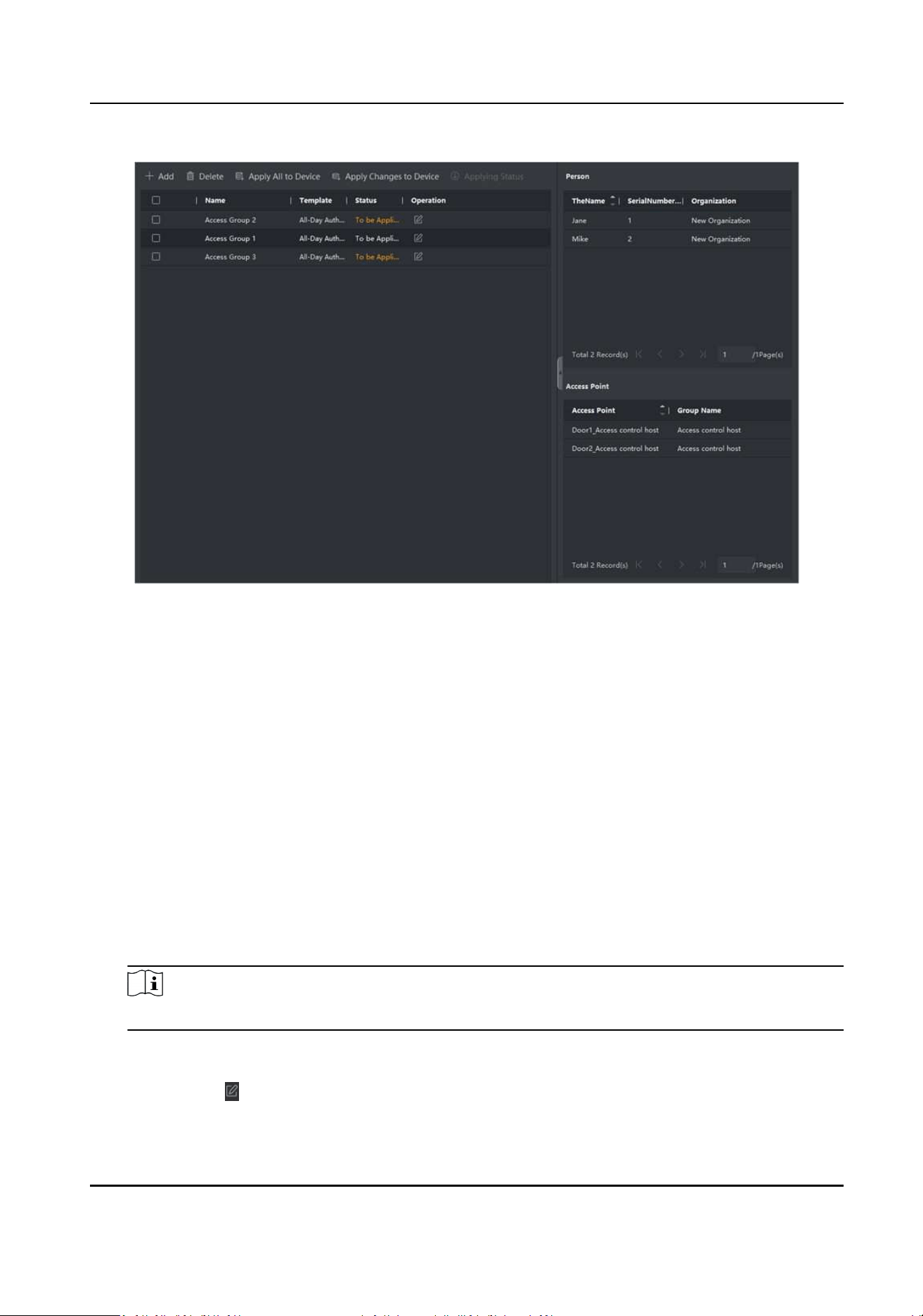
Figure 9-7 Display the Selected Person(s) and Access Point(s)
8.
Aer adding the access groups, you need to apply them to the access control device to take
eect.
1) Select the access group(s) to apply to the access control device.
2) Click Apply All to Devices start applying all the selected access group(s) to the access control
device or door staon.
3) Click Apply All to Devices or Apply Changes to Devices.
Apply All to Devices
This operaon will clear all the existed access groups of the selected devices and then
apply the new access group to the device.
Apply Changes to Devices
This operaon will not clear the existed access groups of the selected devices and only
apply the changed part of the selected access group(s) to the device(s).
4) View the applying status in the Status column or click Applying Status to view all the applied
access group(s).
Note
You can check Display Failure Only to lter the applying results.
The selected persons in the applied access groups will have the authorizaon to enter/exit the
selected doors/door staons with their linked card(s).
9.
Oponal: Click to edit the access group if necessary.
DS-K1TA70 Series Face Recognion Terminal User Manual
134
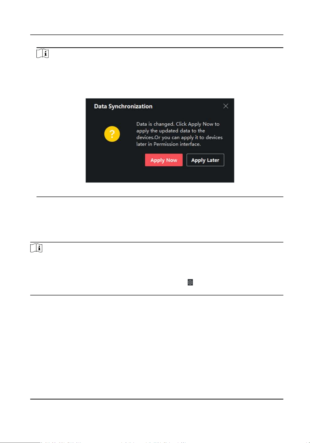
Note
If you change the persons' access informaon or other related informaon, you will view the
prompt Access Group to Be Applied on the right corner of the client.
You can click the prompt to apply the changed data to the device. You can select either Apply
Now or Apply Later.
Figure 9-9 Data Synchronizaon
9.7 Congure Advanced Funcons
You can congure the advanced funcons of access control to meet some special requirements in
dierent scene.
Note
●
For the card related funcons(the type of access control card), only the card(s) with access group
applied will be listed when adding cards.
●
The advanced funcons should be supported by the device.
●
Hover the cursor on the Advanced Funcon, and then Click to customize the advanced
funcon(s) to be displayed.
9.7.1 Congure Device Parameters
Aer adding the access control device, you can congure the parameters of access control device,
access control points.
DS-K1TA70 Series Face Recognion Terminal User Manual
135
Congure Parameters for Access Control Device
Aer adding the access control device, you can congure its parameters, including overlaying user
informaon on picture, uploading pictures aer capturing, saving captured pictures, etc.
Steps
1.
Click Access Control → Advanced Funcon → Device Parameter .
Note
If you can nd Device Parameter in the Advanced Funcon list, Hover the cursor on the
Advanced Funcon, and then Click to select the Device Parameter to be displayed.
2.
Select an access device to show its parameters on the right page.
3.
Turn the switch to ON to enable the corresponding funcons.
Note
●
The displayed parameters may vary for dierent access control devices.
●
Some of the following parameters are not listed in the Basic Informaon page, click More to
edit the parameters.
Voice Prompt
If you enable this funcon, the voice prompt is enabled in the device. You can hear the voice
prompt when operang in the device.
Upload Pic. Aer Linked Capture
Upload the pictures captured by linked camera to the system automacally.
Save Pic. Aer Linked Capture
If you enable this funcon, you can save the picture captured by linked camera to the device.
Face Recognion Mode
Normal Mode
Recognize face via the camera normally.
Deep Mode
The device can recognize a much wider people range than the normal mode. This mode is
applicable to a more complicated environment.
Enable NFC Card
If enable the funcon, the device can recognize the NFC card. You can present NFC card on
the device.
Enable M1 Card
If enable the funcon, the device can recognize the M1 card. You can present M1 card on the
device.
Enable EM Card
DS-K1TA70 Series Face Recognion Terminal User Manual
136
If enable the funcon, the device can recognize the EM card. You can present EM card on the
device.
Note
If the peripheral card reader supports presenng EM card, the funcon is also supported to
enable/disable the EM card funcon.
4.
Click OK.
5.
Oponal: Click Copy to, and then select the access control device(s) to copy the parameters in
the page to the selected device(s).
Congure Parameters for Door
Aer adding the access control device, you can congure its access point door parameters.
Steps
1.
Click Access Control → Advanced Funcon → Device Parameter .
2.
Select an access control device on the le panel, and then click to show the doors of the
selected device.
3.
Select a door to show its parameters on the right page.
4.
Edit the door parameters.
Note
The displayed parameters may vary for dierent access control devices.
●
●
Some of the following parameters are not listed in the Basic Informaon page, click Advanced
to edit the parameters.
Name
Edit the card reader name as desired.
Door Contact
You can set the door sensor as remaining closed or remaining open. Usually, it is remaining
closed.
Exit Buon Type
You can set the exit buon as remaining closed or remaining open. Usually, it is remaining
open.
Open Duraon
Aer swiping the normal card and relay acon, the mer for locking the door starts working.
Super Password
The specic person can open the door by inpung the super password.
Door Le Open Timeout Alarm
DS-K1TA70 Series Face Recognion Terminal User Manual
137
The alarm can be triggered if the door has not been closed in a congured me period. If it is
set as 0, no alarm will be triggered.
Click Advanced to congure more parameters.
Extended Open Duraon
The door contact can be enabled with appropriate delay aer person with extended accesss
needs swipes her/his card.
Duress Code
The door can open by inpung the duress code when there is duress. At the same me, the
client can report the duress event.
Note
●
The duress code and the super code should be dierent.
●
The duress code and super password should be dierent from the authencaon password.
●
The length of duress code and the super password is according to the device, usually it should
contains 4 to 8 digits.
5.
Click OK.
6.
Oponal: Click Copy to , and then select the door/oor(s) to copy the parameters in the page to
the selected doors/oor(s).
Note
The door's status duraon sengs will be copied to the selected doors as well.
Congure Parameters for Card Reader
Aer adding the access control device, you can congure its card reader parameters.
Steps
1.
Click Access Control → Advanced Funcon → Device Parameter .
2.
In the device list on the le, click
to expand the door, select a card reader and you can edit the
card reader's parameters on the right.
3.
Edit the card reader basic parameters in the Basic Informaon page.
Note
●
The displayed parameters may vary for dierent access control devices. There are part of
parameters listed as follows. Refer to the user manual of the device for more details.
●
Some of the following parameters are not listed in the Basic Informaon page, click Advanced
to edit the parameters.
Basic Informaon
Name
Edit the card reader name as desired.
DS-K1TA70 Series Face Recognion Terminal User Manual
138

Minimum Card Swiping Interval
If the interval between card swiping of the same card is less than the set value, the card
swiping is invalid. You can set it as 0 to 255.
Alarm of Max. Failed Aempts
Enable to report alarm when the card reading aempts reach the set value.
Card Reader Type/Card Reader Descripon
Get card reader type and descripon. They are read-only.
Advanced
Enable Card Reader
Enable the funcon and e device can be used as an card reader.
OK LED Polarity/Error LED Polarity/Buzzer Polarity
Set OK LED Polarity/Error LED Polarity/Buzzer LED Polarity of main board according to the
card reader parameters. Generally, adopts the default sengs.
Max. Interval When Entering PWD
When you inpung the password on the card reader, if the interval between pressing two
digits is larger than the set value, the digits you pressed before will be cleared
automacally.
Tampering Detecon
Enable the an-tamper detecon for the card reader.
Communicate with Controller Every
When the access control device cannot connect with the card reader for longer than the
set me, the card reader will turn oine automacally.
Face 1:N Matching Threshold
Set the matching threshold when authencang via 1:N matching mode. The larger the
value, the smaller the false accept rate and the larger the false rejecon rate when
authencaon.
Face Recognion Interval
The me interval between two connuous face recognions when authencang.
Face An-Spoong
Enable or disable the live face detecon funcon. If enabling the funcon, the device can
recognize whether the person is a live one or not.
Face 1:1 Matching Threshold
Set the matching threshold when authencang via 1:1 matching mode. The larger the
value, the smaller the false accept rate and the larger the false rejecon rate when
authencaon.
Applicaon Mode
DS-K1TA70 Series Face Recognion Terminal User Manual
139

You can select indoor or others applicaon modes according to actual environment.
Lock Authencaon Failed Face
Aer enabling the Live Face Detecon funcon, the system will lock the user's face for 5
minutes if the live face detecon is failed for more than the congured aempts. The
same user cannot authencate via the fake face within 5 minutes. Within the 5 minutes,
the user can authencate via the real face twice connuously to unlock.
Liveness Level
Aer enabling Face An-Spoong funcon, you can set the matching security level when
performing live face authencaon.
4.
Click OK.
5.
Oponal: Click Copy to, and then select the card reader(s) to copy the parameters in the page to
the selected card reader(s).
Congure Parameters for Alarm Output
Aer adding the access control device, if the device links to alarm outputs, you can congure the
parameters.
Before You Start
Add access control device to the client, and make sure the device supports alarm output.
Steps
1.
Click Access Control → Advanced Funcon → Device Parameter to enter access control
parameter conguraon page.
2.
In the device list on the le, click to expand the door, select an alarm input and you can edit
the alarm input's parameters on the right.
3.
Set the alarm output parameters.
Name
Edit the card reader name as desired.
Alarm Output Acve Time
How long the alarm output will last aer triggered.
4.
Click OK.
5.
Oponal: Set the switch on the upper right corner to ON to trigger the alarm output.
9.7.2 Congure Remaining Open/Closed
You can set the status of the door as open or closed. For example, you can set the door remaining
closed in the holiday, and set the door remaining open in the specied period of the work day.
Before You Start
Add the access control devices to the system.
DS-K1TA70 Series Face Recognion Terminal User Manual
140
Steps
1.
Click Access Control → Advanced Funcon → Remain Open/Closed to enter the Remain Open/
Closed page.
2.
Select the door that need to be congured on the le panel.
3.
To set the door status during the work day, click the Week Schedule and perform the following
operaons.
1) Click Remain Open or Remain Closed.
2) Drag the cursor to draw the me duraon, which means in that duraon of me, the
congured access group is acvated.
Note
Up to 8 me duraons can be set to each day in the week schedule.
3) Oponal: Perform the following operaons to edit the me duraons.
●
Move the cursor to the me duraon and drag the me duraon on the meline bar to the
desired posion when the cursor turns to .
●
Click the me duraon and directly edit the start/end me in the appeared dialog.
●
Move the cursor to the start or the end of me duraon and drag to lengthen or shorten
the me duraon when the cursor turns to .
4) Click Save.
Related Operaons
Copy to Whole
Week
Select one duraon on the me bar, click Copy to Whole Week to copy all
the duraon sengs on this me bar to other week days.
Delete Selected Select one duraon on the me bar, click Delete Selected to delete this
duraon.
Clear Click Clear to clear all the duraon sengs in the week schedule.
4.
To set the door status during the holiday, click the Holiday and perform the following operaons.
1) Click Remain Open or Remain Closed.
2) Click Add.
3) Enter the start date and end date.
4) Drag the cursor to draw the me duraon, which means in that duraon of me, the
congured access group is acvated.
Note
Up to 8 me duraons can be set to one holiday period.
5) Perform the following operaons to edit the me duraons.
●
Move the cursor to the me duraon and drag the me duraon on the meline bar to the
desired posion when the cursor turns to .
●
Click the me duraon and directly edit the start/end me in the appeared dialog.
●
Move the cursor to the start or the end of me duraon and drag to lengthen or shorten
the me duraon when the cursor turns to .
DS-K1TA70 Series Face Recognion Terminal User Manual
141
6) Oponal: Select the me duraon(s) that need to be deleted, and then click in the
Operaon column to delete the selected me duraon(s).
7) Oponal: Click in the Operaon column to clear all the me duraon(s) in the me bar.
8) Oponal: Click in the Operaon column to delete this added holiday period from the
holiday list.
9) Click Save.
5.
Oponal: Click Copy to to copy the door status sengs of this door to other door(s).
9.7.3 Congure Mul-Factor Authencaon
You can manage the persons by group and set the authencaon for mulple persons of one
access control point (door).
Before You Start
Set access group and apply the access group to the access control device. For details, refer to Set
Access Group to Assign Access Authorizaon to Persons .
Perform this task when you want to set authencaons for mulple cards of one access control
point (door).
Steps
1.
Click Access Control → Advanced Funcon → Mul-Factor Auth .
2.
Select an access control device in device list on the le panel.
3.
Add a person/card group for the access control device.
1) Click Add on the right panel.
2) Create a name for the group as desired.
3) Specify the start me and end me of the eecve period for the person/card group.
4) Select members(s) and card(s) in the Available list, and the selected member(s) and card(s)
will be added to the Selected list.
Note
Make sure you have issue card to the person.
Make sure you have set access group and apply the access group to the access control device
successfully.
5) Click Save.
6) Oponal: Select the person/card group(s), and then click Delete to delete it(them).
7) Oponal: Select the person/card group(s), and then click Apply to re-apply access group that
failed to be applied previously to the access control device.
4.
Select an access control point (door) of selected device on the le panel.
5.
Enter the maximum interval when entering password.
6.
Add an authencaon group for the selected access control point.
1) Click Add on the Authencaon Groups panel.
2) Select a congured template as the authencaon template from the drop-down list.
DS-K1TA70 Series Face Recognion Terminal User Manual
142
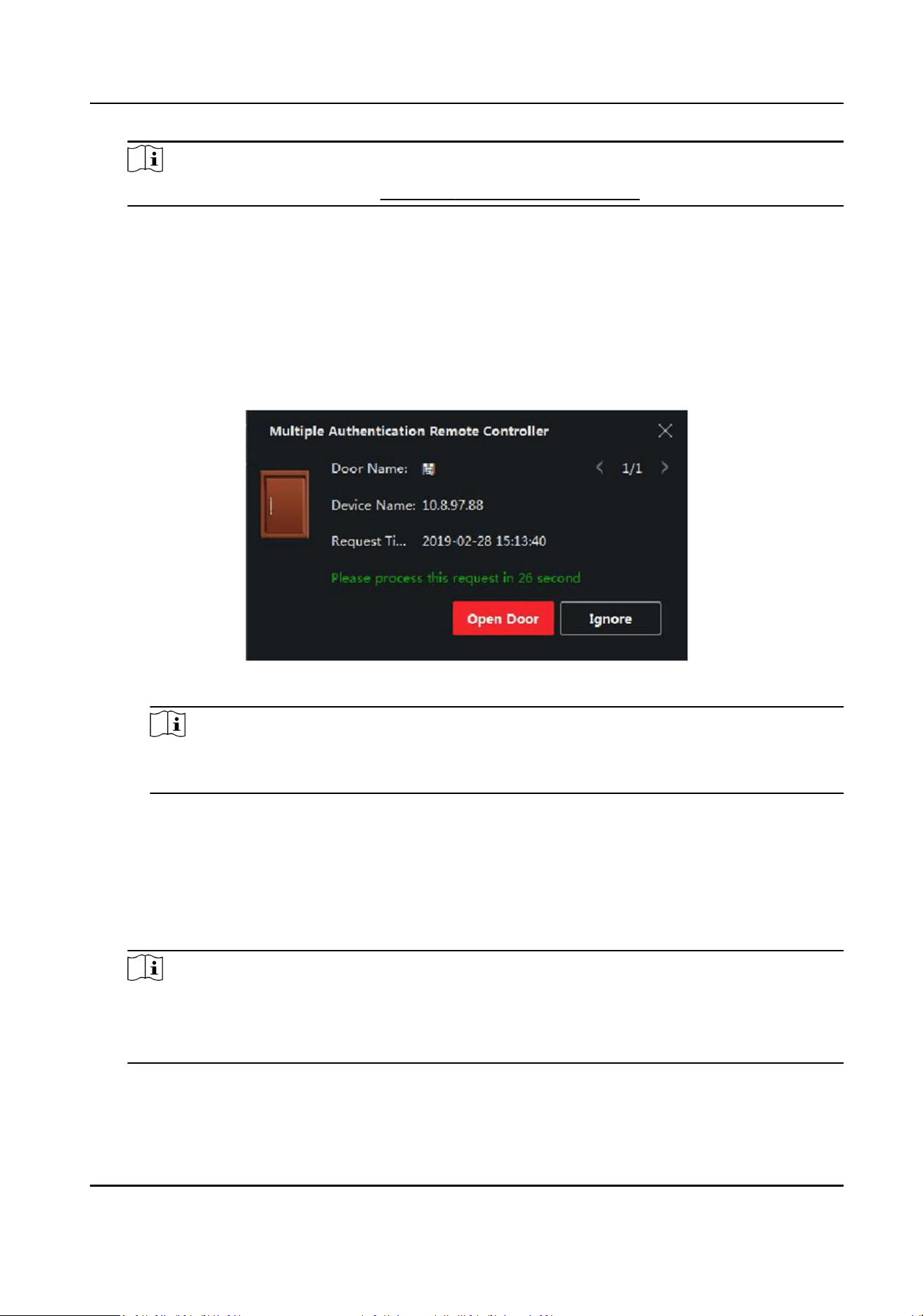
Note
For seng the template, refer to Congure Schedule and Template .
3) Select the authencaon type as Local Authencaon, Local Authencaon and Remotely
Open Door, or Local Authencaon and Super Password from the drop-down list.
Local Authencaon
Authencaon by the access control device.
Local Authencaon and Remotely Open Door
Authencaon by the access control device and by the client. When the person swipes the
card on the device, a window will pop up. You can unlock the door via the client.
Figure 9-10 Remotely Open Door
Note
You can check Oine Authencaon to enable the super password authencaon when
the access control device is disconnected with the client.
Local Authencaon and Super Password
Authencaon by the access control device and by the super password.
4) Select the added person/card group in the le list below and it will be added to the Selected
list on the right as the authencaon group.
5) Click the added authencaon group in the right list to set authencaon mes in the Auth
Times column.
Note
●
The authencaon mes should be larger than 0 and smaller than the added personnel
quanty in the personnel group.
●
The maximum value of authencaon mes is 16.
6) Click Save.
DS-K1TA70 Series Face Recognion Terminal User Manual
143

Note
●
For each access control point (door), up to four authencaon groups can be added.
●
For the authencaon group of which authencaon type is Local Authencaon, up to 8
person/card groups can be added to the authencaon group.
●
For the authencaon group of which authencaon type is Local Authencaon and Super
Password or Local Authencaon and Remotely Open Door, up to 7 person/card groups can
be added to the authencaon group.
7.
Click Save.
9.7.4 Congure Card Reader Authencaon Mode and Schedule
You can set the passing rules for the card reader of the access control device according to your
actual needs.
Steps
1.
Click Access Control → Advanced Funcon → Authencaon to enter the authencaon mode
conguraon page.
2.
Select a card reader on the le to congure.
3.
Set card reader authencaon mode.
1) Click Conguraon.
DS-K1TA70 Series Face Recognion Terminal User Manual
144
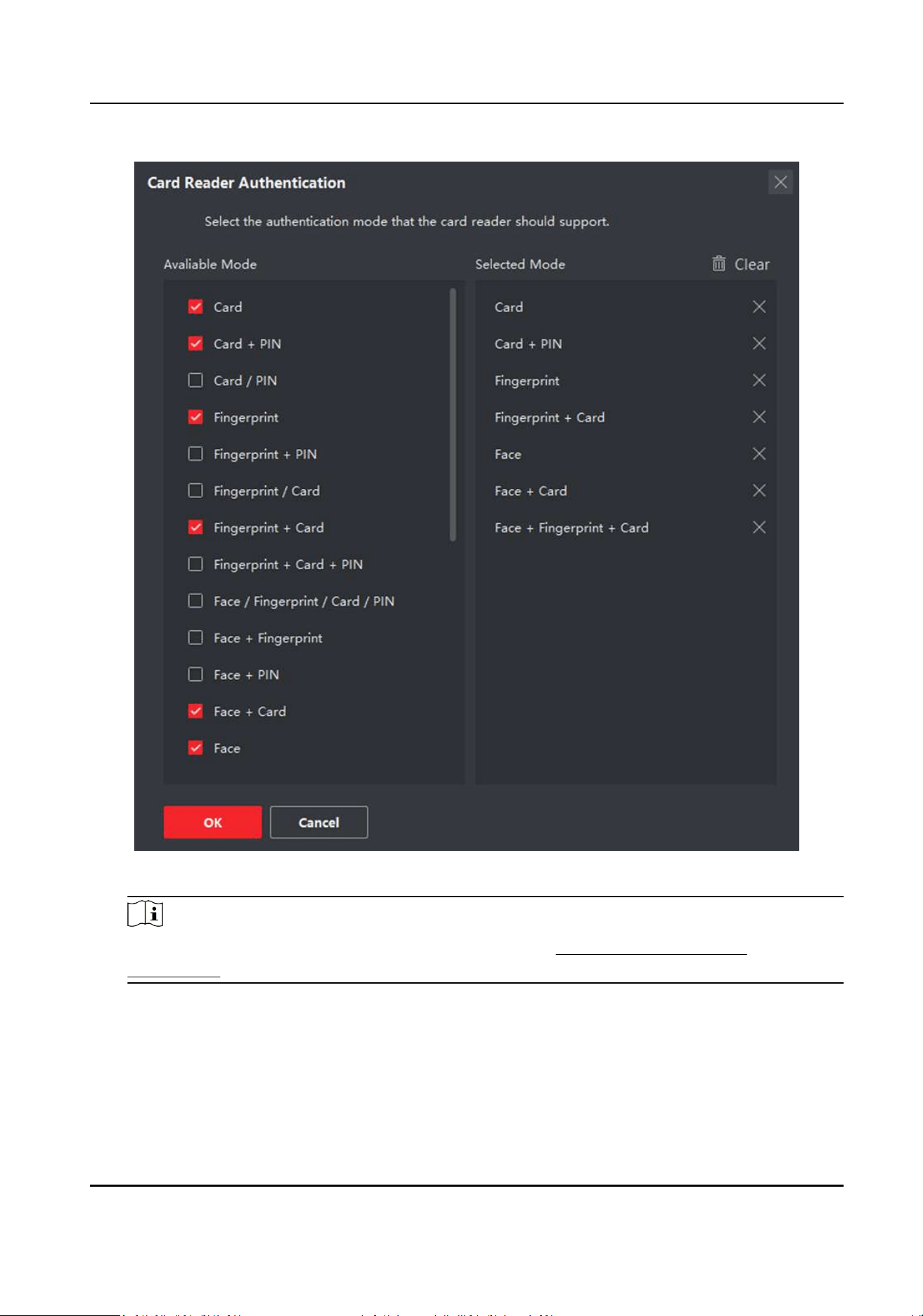
Figure 9-11 Select Card Reader Authencaon Mode
Note
PIN refers to the PIN code set to open the door. Refer to Congure Access Control
Informaon .
2) Check the modes in the Available Mode list and they will be added to the selected modes list.
3) Click OK.
Aer selecng the modes, the selected modes will display as icons with dierent color.
4.
Click the icon to select a card reader authencaon mode, and drag the cursor to draw a color
bar on the schedule, which means in that period of me, the card reader authencaon is valid.
5.
Repeat the above step to set other me periods.
DS-K1TA70 Series Face Recognion Terminal User Manual
145
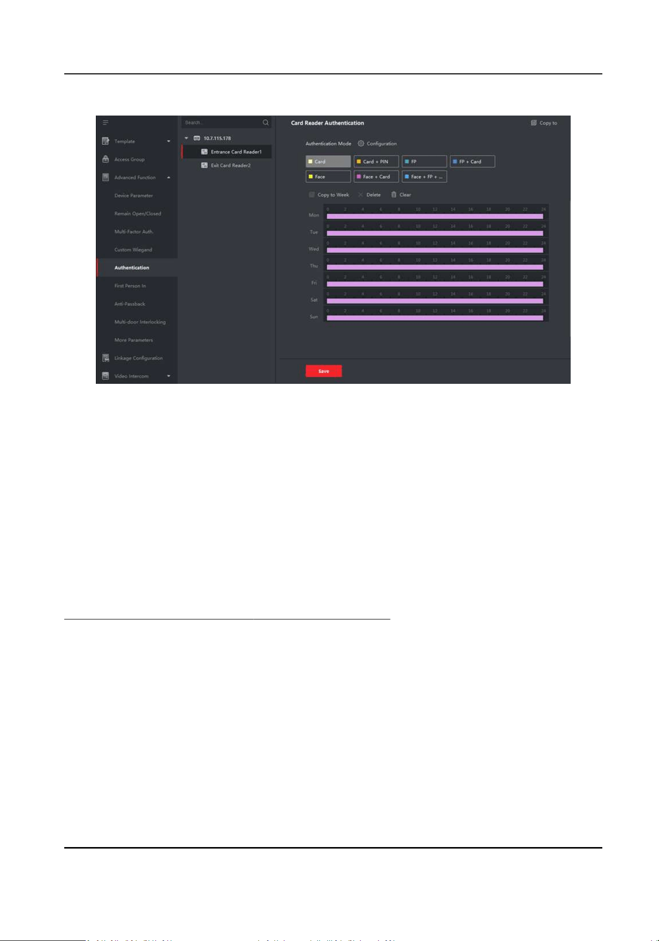
Figure 9-12 Set Authencaon Modes for Card Readers
6.
Oponal: Select a congured day and click Copy to Week to copy the same sengs to the whole
week.
7.
Oponal: Click Copy to to copy the sengs to other card readers.
8.
Click Save.
9.7.5 Congure First Person In
You can set mulple rst persons for one access control point. Aer the rst person is authorized,
it allows mulple persons access the door or other authencaon acons.
Before You Start
Set the access group and apply the access group to the access control device. For details, refer to
Set Access Group to Assign Access Authorizaon to Persons .
Perform this task when you want to congure opening door with rst person.
Steps
1.
Click Access Control → Advanced Funcon → First Person In to enter the First Person In page.
2.
Select an access control device in the list on the le panel.
3.
Select the current mode as Enable Remaining Open aer First Person or Disable Remaining
Open aer First Person from the drop-down list for each access control point of the selected
device.
Enable Remaining Open aer First Person
DS-K1TA70 Series Face Recognion Terminal User Manual
146
The door remains open for the congured me duraon aer the rst person is authorized
unl the remain open duraon ends. If you select this mode, you should set the remain open
duraon.
Note
The remain open duraon should be between 0 and 1440 minutes. By default, the remain
open duraon is 10 minutes.
Disable Remaining Open aer First Person
Disable the funcon of rst person in, namely normal authencaon.
Note
You can authencate by the rst person again to disable the rst person mode.
4.
Click Add on the First Person List panel.
5.
Select person(s) in the le list and the person(s) will be add to the selected persons as the rst
person(s) of the doors.
The added rst person(s) will list in the First Person List
6.
Oponal: Select a rst person from the list and click Delete to remove the person from the rst
person list.
7.
Click Save.
9.7.6 Congure An-Passback
The an-passback feature is designed to minimizes the misuse or fraudulent use of access
credenals such as passing back card to an unauthorized person, or tailed access. The an-
passback funcon establishes a specic sequence in which access credenals must be used in
order to grant access. You can set the sequence according to the actual path via the client and if
the person uses the credenal in wrong sequence, you can also reset the an-password records.
Before You Start
Add access control device to the client, and enable the an-passing back funcon of the access
control device.
Steps
Note
Either the an-passing back or mul-door interlocking funcon can be congured for an access
control device at the same me. For the conguraon of mul-door interlocking, refer to .
1.
Click Access Control → Advanced Funcon → An-Passback to enter the An-Passpack Sengs
page.
2.
Select an access control device on the le panel.
3.
Select a card reader as the beginning of the path in the First Card Reader eld.
DS-K1TA70 Series Face Recognion Terminal User Manual
147
4.
Click of the selected rst card reader in the Card Reader Aerward column to open the select
card reader dialog.
5.
Select the aerward card readers for the rst card reader.
Note
Up to four aerward card readers can be added as aerward card readers for one card reader.
6.
Click OK in the dialog to save the selecons.
7.
Click Save in the An-Passback Sengs page to save the sengs and take eect.
Example
Set Card Swiping Path: If you select Reader In_01 as the beginning, and select Reader In_02,
Reader Out_04 as the linked card readers. Then you can only get through the access control
point by swiping the card in the order as Reader In_01, Reader In_02 and Reader Out_04.
8.
Click Reset An-Passback and select the person(s) to delete the related an-passback records
about the person(s) on the device.
Note
This funcon should be supported by the device.
9.7.7 Congure Device Parameters
Aer adding the access control device, you can set its parameters such as network parameters.
Set Mulple NIC Parameters
If the device supports mulple network interfaces, you can set the network parameters of these
NICs via the client, such as IP address, MAC address, port number, etc.
Before You Start
Add access control device to the client, and make sure the device supports mulple NICs.
Steps
1.
Enter the Access Control module.
2.
On the navigaon bar on the le, enter Advanced Funcon → More Parameters .
3.
Select an access control device in the device list and click NIC to enter Mulple NIC Sengs
page.
4.
Select an NIC you want to congure from the drop-down list.
5.
Set its network parameters such as IP address, default gateway, subnet mask, etc.
MAC Address
A media access control address (MAC address) is a unique idener assigned to the network
interface for communicaons on the physical network segment.
MTU
DS-K1TA70 Series Face Recognion Terminal User Manual
148

The maximum transmission unit (MTU) of the network interface.
6.
Click Save.
Set Network Parameters
Aer adding the access control device, you can set the device log uploading mode, and create ISUP
account via wired or wireless network.
Set Log Uploading Mode
You can set the mode for the device to upload logs via ISUP protocol.
Steps
1.
Enter the Access Control module.
2.
On the navigaon bar on the le, enter Advanced Funcon → More Parameters .
3.
Select an access control device in the device list and enter Network → Uploading Mode .
4.
Select the center group from the drop-down list.
5.
Check Enable to enable to set the uploading mode.
6.
Select the uploading mode from the drop-down list.
-
Enable N1 or G1 for the main channel.
-
Select Close to disable the main channel.
7.
Click Save.
Create ISUP Account in Wired Communicaon Mode
You can set the account for ISUP protocol in wired communicaon mode. Then you can add
devices via ISUP protocol.
Steps
Note
This funcon should be supported by the device.
1.
Enter the Access Control module.
2.
On the navigaon bar on the le, enter Advanced Funcon → More Parameters .
3.
Select an access control device in the device list and enter Network → Network Center .
4.
Select the center group from the drop-down list.
5.
Select the Address Type as IP Address or Domain Name.
6.
Enter IP address or domain name according to the address type.
7.
Enter the port number for the protocol.
DS-K1TA70 Series Face Recognion Terminal User Manual
149
Note
The port number of the wireless network and wired network should be consistent with the port
number of ISUP.
8.
Select the Protocol Type as ISUP.
Note
If set the ISUP version as 5.0, you should create an ISUP key for the ISUP account.
9.
Set an account name for the network center.
10.
Click Save.
Set Device Capture Parameters
You can congure the capture parameters of the access control device, including manual capture
and event triggered capture.
Note
●
The capture funcon should be supported by the device.
●
Before seng the capture parameters, you should set the picture storage rst to dene where
the event triggered pictures are saved. For details, refer to Set Picture Storage in the user
manual of the client soware. .
Set Triggered Capture Parameters
When an event occurs, the camera of the access control device can be triggered to capture
picture(s) to record what happens when the event occurs. You can view the captured pictures
when checking the event details in Event Center. Before that, you need to set the parameters for
the capture such as number of pictures captured for one me.
Before You Start
Before seng the capture parameters, you should set the picture storage rst to dene where the
captured pictures are saved. For details, refer to Set Picture Storage in the user manual of the
client soware.
Steps
Note
This funcon should be supported by the device
1.
Enter the Access Control module.
2.
On the navigaon bar on the le, enter Advanced Funcon → More Parameters → Capture .
3.
Select an access control device in the device list and select Linked Capture.
4.
Set the picture size and quality.
DS-K1TA70 Series Face Recognion Terminal User Manual
150
5.
Set the capture mes once triggered which denes how many pictures will be captures for one
me.
6.
If the capture mes is more than 1, set the interval for each capture.
7.
Click Save.
Set Manual Capture Parameters
In Status Monitoring module, you can capture a picture manually the access control device's
camera by clicking a buon. Before that, you need to set the parameters for the capture such as
picture quality.
Before You Start
Before seng the capture parameters, you should set the saving path rst to dene where the
captured pictures are saved. For details, refer to Set Picture Storage in the user manual of the
client soware.
Steps
Note
This funcon should be supported by the device
1.
Enter the Access Control module.
2.
On the navigaon bar on the le, enter Advanced Funcon → More Parameters → Capture .
3.
Select an access control device in the device list and select Manual Capture.
4.
Select the resoluon of the captured pictures from the drop-down list.
5.
Select the picture quality as High, Medium, or Low. The higher the picture quality is, the larger
size the picture will be.
6.
Click Save.
Set Parameters for Face Recognion Terminal
For face recognion terminal, you can set its parameters including face picture database, etc.
Steps
Note
This funcon should be supported by the device.
1.
Enter the Access Control module.
2.
On the navigaon bar on the le, enter Advanced Funcon → More Parameters .
3.
Select an access control device in the device list and click Face Recognion Terminal.
4.
Set the parameters.
DS-K1TA70 Series Face Recognion Terminal User Manual
151
Note
These parameters displayed vary according to dierent device models.
Algorithm
Select Deep Learning as the face picture database.
Save Authencaon Picture
If enabled, the captured face picture when authencang will be saved on the device.
ECO Mode
Aer enabling the ECO mode, the device can authencate faces in the low light or dark
environment. And you can set he ECO mode threshold, ECO mode (1:N), and ECO mode (1:1).
ECO Mode (1:1)
Set the matching threshold when authencang via ECO mode 1:1 matching mode. The
larger the value, the smaller the false accept rate and the larger the false rejecon rate.
ECO Mode (1:N)
Set the matching threshold when authencang via ECO mode 1:N matching mode. The
larger the value, the smaller the false accept rate and the larger the false rejecon rate.
ECO Mode Threshold
When enabling the ECO mode, you can set the ECO mode's threshold. The larger the value,
the easier the device entering the ECO mode. Available range: 0 to 8.
Face with Mask & Face 1:N (ECO)
Set the matching threshold when authencang via face with mask & face in ECO mode 1:N
matching mode. The larger the value, the smaller the false accept rate and the larger the false
rejecon rate.
Work Mode
Set the device work mode as Access Control Mode. The access control mode is the device
normal mode. You should authencate your credenal for accessing.
5.
Click Save.
Enable M1 Card Encrypon
M1 card encrypon can improve the security level of authencaon.
Steps
Note
The funcon should be supported by the access control device and the card reader.
1.
Enter the Access Control module.
2.
On the navigaon bar on the le, enter Advanced Funcon → More Parameters .
DS-K1TA70 Series Face Recognion Terminal User Manual
152
3.
Select an access control device in the device list and click M1 Card Encrypon Vericaon to
enter the M1 Card Encrypon Vericaon page.
4.
Set the switch to on to enable the M1 card encrypon funcon.
5.
Set the sector ID.
Note
●
The sector ID ranges from 1 to 100.
●
By default, Sector 13 is encrypted. It is recommended to encrypt sector 13.
6.
Click Save to save the sengs.
Set RS-485 Parameters
You can set the access control device's RS-485 parameters including the baud rate, data bit, the
stop bit, parity type, ow control type, communicaon mode, work mode, and connecon mode.
Steps
Note
The RS-485 Sengs should be supported by the device.
1.
Enter the Access Control module.
2.
On the navigaon bar on the le, enter Advanced Funcon → More Parameters .
3.
Select an access control device in the device list and click RS-485 to enter the RS-485 Sengs
page.
4.
Select the serial port number from the drop-down list to set the RS-485 parameters.
5.
Set the serial number, external device, authencaon center, baud rate, data bit, stop bit, parity
type, ow control type, communicaon mode, and working mode in the drop-down list.
6.
Click Save.
●
The congured parameters will be applied to the device automacally.
●
When you change the working mode or connecon mode, the device will reboot
automacally.
Set Wiegand Parameters
You can set the access control device's Wiegand channel and the communicaon mode. Aer
seng the Wiegand parameters, the device can connect to Wiegand card reader via Wiegand
communicaon.
Steps
Note
This funcon should be supported by the device.
1.
Enter the Access Control module.
DS-K1TA70 Series Face Recognion Terminal User Manual
153
2.
On the navigaon bar on the le, enter Advanced Funcon → More Parameters .
3.
Select an access control device in the device list and click Wiegand to enter the Wiegand
Sengs page.
4.
Set the switch to on to enable the Wiegand funcon for the device.
5.
Select the Wiegand channel No. and the communicaon mode from the drop-down list.
Note
If you set Communicaon Direcon as Sending, you are required to set the Wiegand Mode as
Wiegand 26 or Wiegand 34.
6.
Check Enable Wiegand to enable the Wiegand funcon.
7.
Click Save.
●
The congured parameters will be applied to the device automacally.
●
Aer changing the communicaon direcon, the device will reboot automacally.
9.8 Congure Linkage Acons for Access Control
You can congure dierent linkage acons for the event detected by the access control device.
Aer that, linkage acons will be triggered once the event happens. This mechanism is used for
nofying the security personnel the event, or triggering automac access control in real me.
Two types of linkage acons are supported:
●
Client Acons: When the event is detected, it will trigger the acons on the client, such as the
client making an audible warning..
●
Device Acons: When the event is detected, it will trigger the acons of a specic device, such
as buzzing of a card reader and, opening/closing of a door, ..
9.8.1 Congure Client Acons for Access Event
Even if you are far away from an access point, you can sll know what happens and how urgent the
event is by conguring linked acons of access event on the client. You will be noed on the client
once an event is triggered, so that you can response to the event instantly. You can also congure
client acons of access points in a batch at a me.
Steps
Note
The linkage acons here refer to the linkage of the client soware's own acons such as audible
warning, email linkage, etc.
1.
Click Event Management → Access Control Event .
The added access control devices will display in the device list.
2.
Select a resource (including device, alarm input, door/elevator, and card reader) from the device
list.
DS-K1TA70 Series Face Recognion Terminal User Manual
154
The event types which the selected resource supports will display.
3.
Select the event(s) and click Edit Priority to dene the priority for the event(s), which can be
used to lter events in the Event Center.
4.
Set the linkage acons of the event.
1) Select the event(s) and click Edit Linkage to set the client acons when the events triggered.
Audible Warning
The client soware gives an audible warning when alarm is triggered. You can select the
alarm sound for audible warning.
Note
For seng the alarm sound, please refer to Set Alarm Sound in the user manual of client
soware..
Send Email
Send an email nocaon of the alarm informaon to one or more receivers.
For details about seng email parameters, refer to Set Email Parameters in the user
manual of client soware..
2) Click OK.
5.
Enable the event so that when the event is detected, en event will be sent to the client and the
linkage acons will be triggered.
6.
Oponal: Click Copy to... to copy the event sengs to other access control device, alarm input,
door, or card reader.
9.8.2 Congure Device Acons for Access Event
You can set the access control device's linkage acons for the access control device's triggered
event. Aer that, when an event is triggered, it can trigger the alarm output, buzzer on access
controller, and other acons.
Steps
Note
The linkage acons should be supported by the device.
1.
Click Access Control → Linkage Conguraon .
2.
Select the access control device from the list on the le.
3.
Click Add to add a new linkage.
4.
Select Event Linkage as the event source.
5.
select the event type and detailed event to set the linkage.
6.
In the Linkage Target area, set the property target to enable this acon.
Buzzer on Controller
The audible warning of access control device will be triggered.
DS-K1TA70 Series Face Recognion Terminal User Manual
155
Capture
An event-related picture will be captured when the selected event happens.
Recording
An event-related picture will be captured when the selected event happens.
Note
The device should support recording.
Buzzer on Reader
The audible warning of card reader will be triggered.
Alarm Output
The alarm output will be triggered for nocaon when the selected event happens
Alarm Input
Arm or disarm the alarm input.
Note
The device should support alarm input funcon.
Access Point
The door status of open, close, remain open, or remain close will be triggered.
Note
The target door and the source door cannot be the same one.
Audio Play
The audio prompt will be triggered. And the select audio index related audio content will be
played according to the congured play mode.
7.
Click Save.
8.
Oponal: Aer adding the device linkage, you can do one or more of the followings:
Edit Linkage
Sengs
Select the congured linkage sengs in the device list and you can edit its
event source parameters, including event source and linkage target.
Delete Linkage
Sengs
Select the congured linkage sengs in the device list and click Delete to
delete it.
9.8.3 Congure Device Acons for Card Swiping
You enable access control device's linkage acons (such as disarming a zone and triggering audio
prompt) for the swiping of a specic card, In this way, you can monitor the card holder's behaviors
and whereabouts.
DS-K1TA70 Series Face Recognion Terminal User Manual
156
Steps
Note
It should be supported by the device.
1.
Click Access Control → Linkage Conguraon .
2.
Select the access control device from the list on the le.
3.
Click Add to add a new linkage.
4.
Select Card Linkage as the event source.
5.
Enter the card number or select the card from the drop-down list.
6.
Select the card reader where the card swipes.
7.
In the Linkage Target area, set the property target to enable this acon.
Buzzer on Controller
The audible warning of access control device will be triggered.
Buzzer on Reader
The audible warning of card reader will be triggered.
Capture
An event-related picture will be captured when the selected event happens.
Recording
An event-related picture will be captured when the selected event happens.
Note
The device should support recording.
Alarm Output
The alarm output will be triggered for nocaon.
Alarm Input
Arm or disarm the alarm input.
Note
The device should support alarm input funcon.
Access Point
The door status of open, close, remain open, or remain closed will be triggered.
Audio Play
The audio prompt will be triggered. And the select audio index related audio content will be
played according to the congured play mode.
8.
Click Save.
When the card (congured in Step 5) swipes on the card reader (congured in Step 6), it can
trigger the linked acons (congured in step 7).
DS-K1TA70 Series Face Recognion Terminal User Manual
157
9.
Oponal: Aer adding the device linkage, you can do one or more of the followings:
Delete Linkage
Sengs
Select the congured linkage sengs in the device list and click Delete to
delete it.
Edit Linkage
Sengs
Select the congured linkage sengs in the device list and you can edit its
event source parameters, including event source and linkage target.
9.8.4 Congure Device Acons for Person ID
You can set the access control device's linkage acons for the specied person ID. When access
control device detects the specied person ID, it can trigger the alarm output, buzzer on card
reader, and other acons, so as to implement special monitoring on the specied person.
Steps
Note
It should be supported by the device.
1.
Click Access Control → Linkage Conguraon .
2.
Select the access control device from the list on the le.
3.
Click Add to add a new linkage.
4.
Select Person Linkage as the event source.
5.
Enter the employee number or select the person from the drop-down list.
6.
Select the card reader where the card swipes.
7.
In the Linkage Target area, set the property target to enable this acon.
Buzzer on Controller
The audible warning of access control device will be triggered.
Buzzer on Reader
The audible warning of card reader will be triggered.
Capture
An event-related picture will be captured when the selected event happens.
Recording
An event-related picture will be captured when the selected event happens.
Note
The device should support recording.
Alarm Output
The alarm output will be triggered for nocaon.
Alarm Input
Arm or disarm the alarm input.
DS-K1TA70 Series Face Recognion Terminal User Manual
158
Note
The device should support zone funcon.
Access Point
The door status of open, close, remain open, or remain closed will be triggered.
Audio Play
The audio prompt will be triggered. And the select audio index related audio content will be
played according to the congured play mode.
8.
Click Save.
9.
Oponal: Aer adding the device linkage, you can do one or more of the followings:
Delete Linkage
Sengs
Select the congured linkage sengs in the device list and click Delete to
delete it.
Edit Linkage
Sengs
Select the congured linkage sengs in the device list and you can edit its
event source parameters, including event source and linkage target.
9.9 Door Control
In Monitoring module, you can view the real-me status of the doors managed by the added
access control device. You can also control the doors such as open/close the door, or remain the
door open/closed via the client remotely. The real-me access event are displayed in this module.
You can view the access details and person details.
Note
For the user with door control permission, the user can enter the Monitoring module and control
the door. Or the icons used for control will not show. For seng the user permission, refer to
Person Management .
9.9.1 Control Door Status
You can control the status for a single door, including opening door, closing door, remaining the
door open, and remaining the door closed.
Steps
1.
Click Monitoring to enter the status monitoring page.
2.
Select an access point group on the upper-right corner.
Note
For managing the access point group, refer to Group Management in the user manual of the
client soware.
The doors in the selected access control group will display.
DS-K1TA70 Series Face Recognion Terminal User Manual
159
3.
Click a door icon to select a door, or press Ctrl and select mulple doors.
4.
Click the following buons to control the door.
Open Door
When the door is locked, unlock it and it will be open for once. Aer the open duraon, the
door will be closed and locked again automacally.
Close Door
When the door is unlocked, lock it and it will be closed. The person who has the access
authorizaon can access the door with credenals.
Remain Open
The door will be unlocked (no maer closed or open). All the persons can access the door
with no credenals required.
Remain Closed
The door will be closed and locked. No person can access the door even if he/she has the
authorized credenals, except the super users.
Capture
Capture a picture manually.
Note
The Capture buon is available when the device supports capture funcon. The picture is
saved in the PC running the client. For seng the saving path, refer to Set File Saving Path in
the user manual of the client soware.
Result
The icon of the doors will change in real-me according to the operaon if the operaon is
succeeded.
9.9.2 Check Real-Time Access Records
The access records will display in real me, including card swiping records, face recognions
records, comparison records, etc. You can view the person informaon and view the picture
captured during access.
Steps
1.
Click Monitoring and select a group from the drop-down list on the upper-right corner.
The access records triggered at the doors in the selected group will display in real me. You can
view the details of the records, including card No., person name, organizaon, event me, etc.
2.
Oponal: Check the event type and event status so that these events will show in the list if the
events are detected. The events of unchecked type or status will not be displayed in the list.
3.
Oponal: Check Show Latest Event and the latest access record will be selected and displayed at
the top of the record list.
DS-K1TA70 Series Face Recognion Terminal User Manual
160
4.
Oponal: Click the event to view the accessed person details, including person pictures
(captured picture and prole), person No., person name, organizaon, phone, contact address,
etc.
Note
You can double click the captured picture to enlarge it to view the details.
5.
Oponal: Right click on the column name of the access event table to show or hide the column
according to actual needs.
9.10 Event Center
The event informaon (for example, device oine) received by the client displays. In the Event
Center, you can check the detailed informaon of the real-me and historical events, view the
event linked video, handle the events, and so on.
Before the client can receive the event informaon from the device, you need to enable the events
of the resource and arm the device rst. For details, refer to Enable Receiving Event from Devices .
9.10.1 Enable Receiving Event from Devices
Before the client soware can receive event nocaons from the device, you need to arm the
device rst.
Steps
1.
Click → Tool → Device Arming Control to open Device Arming Control page.
All the added devices appear on this page.
2.
Oponal: If there are to many devices, enter the key words in Filter led to lter the device(s)
you want.
Note
For the ltered devices, you can click Arm All or Disarm All to enable receiving event of these
devices.
3.
In the Auto-Arming column, turn on the switch to enable auto-arming.
DS-K1TA70 Series Face Recognion Terminal User Manual
161
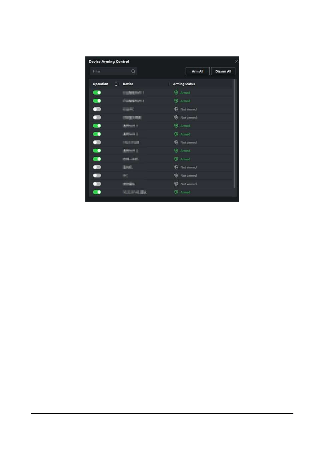
Figure 9-13 Arm Device
Aer turned on, the device(s) will be armed. And nocaons about the events triggered by the
armed device(s) will be automacally sent to the client soware in real-me.
9.10.2 View Real-Time Events
The real-me event informaon received by the client of the connected resources are displayed.
You can check the real-me event informaon, including event source, event me, priority, etc.
Before You Start
Enable receiving events from devices before the client can receive event from the device, see
Enable Receiving Event from Devices for details.
Steps
1.
Click Event Center → Real-me Event to enter the real-me event page and you can view the
real-me events received by the client.
Event Time
For encoding device, event me is the client me when it receives the event. For other device
types, event me is the me when the event is triggered.
Priority
Priority represents the emergency degree of the event.
2.
Filter the events.
DS-K1TA70 Series Face Recognion Terminal User Manual
162
Filter by Device Type and (or)
Priority
Select device type(s) and (or) priories to lter
events.
Filter by Keywords Enter the keywords to lter the events.
3.
Oponal: Right-click the table header of the event list to customize the event related items to be
displayed in the event list.
4.
Select an event in the event list to view the event details.
5.
Oponal: Perform the following operaons if necessary.
Handle Single Event Click Handle to enter the processing suggeson, and then click OK.
Note
Aer an event is handled, the Handle buon will become Add
Remark. Click Add Remark to add more remarks for this handled
event.
Handle Events in a
Batch
Select events that need to be processed, and then click Handle in
Batch. Enter the processing suggeson, and then click OK.
Enable/Disable Alarm
Audio
Click Audio On/Mute to enable/disable the audio of the event.
Select the Latest
Event Automacally
Check Auto-Select Latest Event to select the latest event
automacally and the event informaon details is displayed.
Clear Events Click Clear to clear the all the events in the event list.
Send Email Select an event and then click Send Email, and the informaon
details of this event will be sent by email.
Note
You should congure the email parameters rst, see Set Email
Parameters in the user manual of the client soware for details.
Auto-Play Video Check Auto-Play Video to automacally play video when displaying
event details.
Enlarge Video or
Picture
●
Double click the video image to view video in a larger window.
●
Put the cursor on the picture, and click
to view picture in a
larger window.
Download Captured
Picture
Hover the cursor on the captured picture, and click the download
icon on the lower right corner of the picture to download it to the
local PC.
Download Event
Triggered Video
Hover the cursor on the recorded video, click
to download the
video (30s before the event happens) triggered by the event.
DS-K1TA70 Series Face Recognion Terminal User Manual
163
9.10.3 Search Historical Events
You can search and view historical events by seng search condions such as me, device type,
and priority in the client. For the searched events, you can handle and export them.
Before You Start
Enable receiving events from devices before the client can receive event informaon from the
device,see Enable Receiving Event from Devices for details.
Steps
1.
Click Event Center → Event Search to enter the event search page.
2.
Set the lter condions to display the required events only.
Time
The me when the event starts.
Search by
Device
Search the events by device or the device's resource channels. If searched by device, you
need to set the followings:
●
Include Sub-Node: Search the events of the device and all resource channels.
●
Device Type: Select the device from which you want to search events.
Group
Search the events by resource channels in the group.
Note
●
For video intercom device, you need to select search scope: All and Locking Log.
●
For access control device, you can click Show More to set more condions: status, event
type, card reader type, person name, card No., and organizaon.
Priority
The priority including low, medium, high and uncategorized which indicates the emergency
degree of the event.
Event Type
Select one or more event types to be searched from the drop-down list.
Note
You can enter a key word (supports fuzzy search) in the search box to search the target event
type(s).
Status
The handling status of the event.
Search by Keyword
DS-K1TA70 Series Face Recognion Terminal User Manual
164
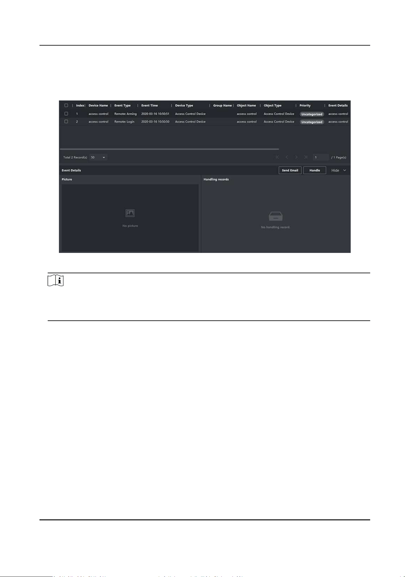
Enter a key word (supports fuzzy search) to quickly search the target historical event(s). For
example, you can enter a person's name to search the events related with this person.
3.
Click Search to search the events according the condions you set.
Figure 9-14 Search Historical Events
Note
If you have selected Access Control as device type in Step 2, you can view extra informaon such
as card No., temperature, and abnormal temperature (if device supports) in the searched
events.
DS-K1TA70 Series Face Recognion Terminal User Manual
165
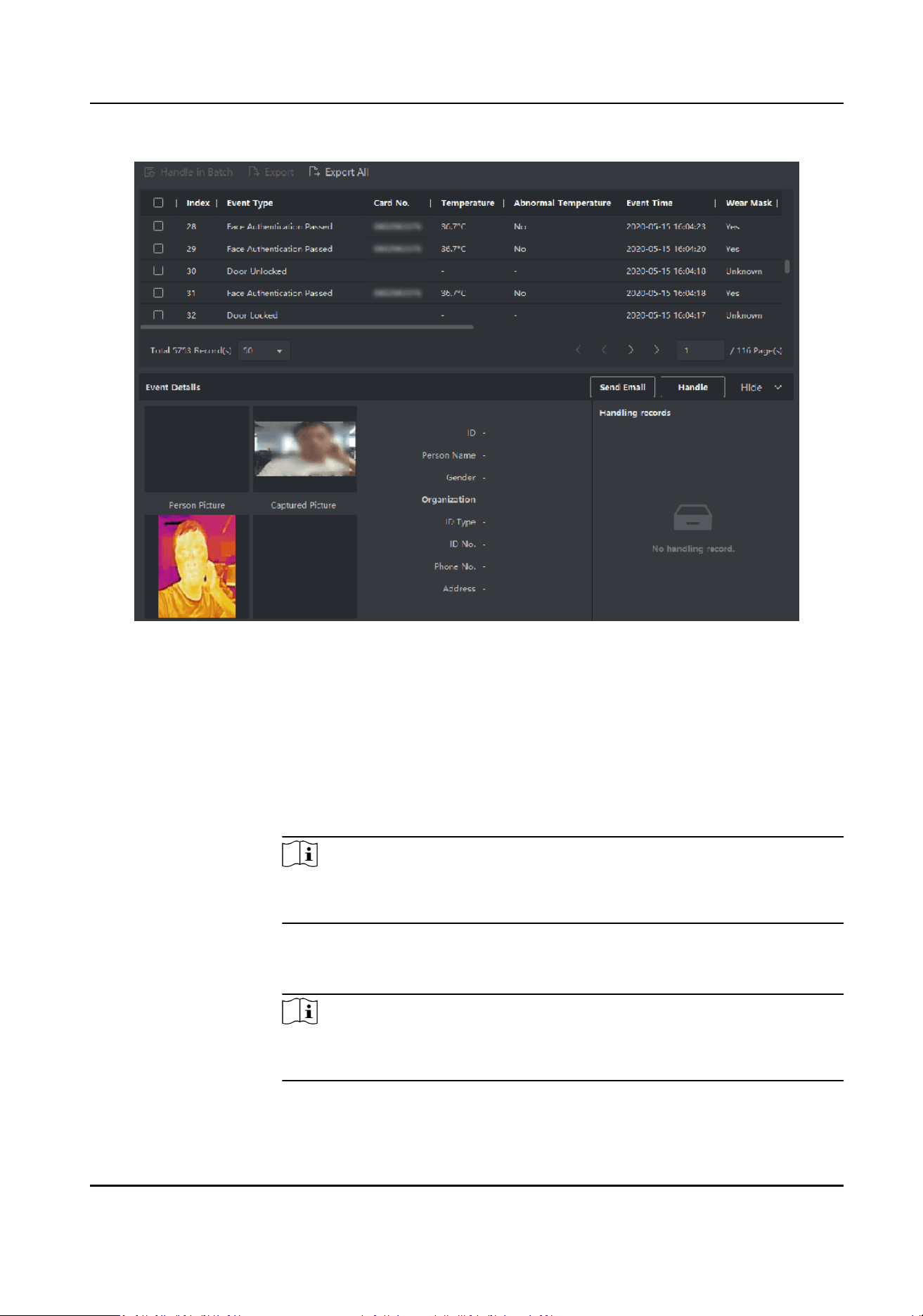
Figure 9-15 Search Historical Event
4.
Oponal: Right click the table header of the event list to customize the event related items to be
displayed in the event list.
5.
Select an event in the event list to view the event details.
6.
Oponal: Perform one of the following operaons.
Handle Single
Event
Handle single event: Select one event that needs to be handled, and then
click Handle in the event informaon details page, and enter the handling
suggeson.
Note
Aer an event is handled, the Handle buon will become Add Remark,
click Add Remark to add more remarks for this handled event.
Batch Handle
Events
Handle events in a batch: Select the events which need to be handled,
and then click Handle in Batch, and enter the handling suggeson.
Note
Aer an event is handled, the Handle buon will become Add Remark,
click Add Remark to add more remarks for this handled event.
DS-K1TA70 Series Face Recognion Terminal User Manual
166
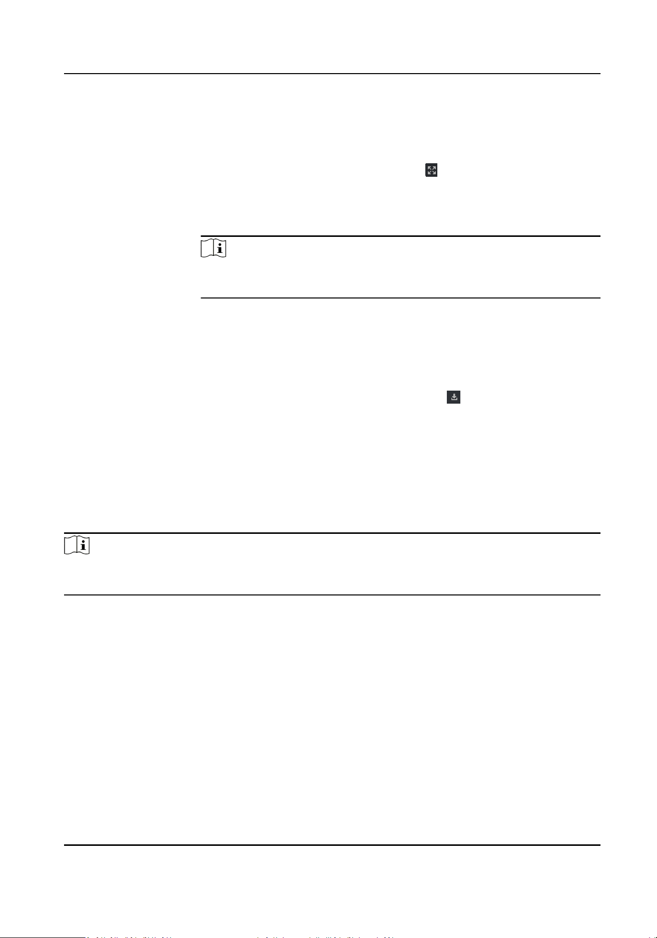
Auto-Play Video Check Auto-Play Video to automacally play video when displaying event
details.
Enlarge Video or
Picture
●
Double click the video image to view video in a larger window.
●
Put the cursor on the picture, and click
to view picture in a larger
window.
Send Email Select an event and then click Send Email, and the informaon details of
this event will be sent by email.
Note
You should congure the email parameters rst, see Set Email Parameters
in the user manual of the client soware for details.
Export Event
Informaon
Click Export to export the event log or event pictures to the local PC in
CSV/Excel le. You can set the saving path manually.
Download
Captured Picture
Hover the cursor on the captured picture, and click the download icon on
the lower right corner of the picture to download it to the local PC.
Download Event
Triggered Video
Hover the cursor on the recorded video, click
to download the video
(30s before the event happens) triggered by the event.
9.11 Time and Aendance
The Time and Aendance module provides mulple funconalies to track and monitor when
employees start and stop work, and full control of employees working hours such as late arrivals,
early departures, me taken on breaks and absenteeism.
Note
In this secon, we introduce the conguraons before you can geng the aendance reports. The
access records recorded aer these conguraons will be calculated in the stascs.
9.11.1 Congure Aendance Parameters
You can congure the aendance parameters, including the general rule, overme parameters,
aendance check point, holiday, leave type, etc.
Set Weekend
The days of weekends may vary in dierent countries and regions. The client provides weekends
denion funcon. You can select one or more days as the weekends according to actual
requirements, and set dierent aendance rules for weekends from workdays.
DS-K1TA70 Series Face Recognion Terminal User Manual
167

Steps
Note
The parameters congured here will be set as default for the newly added me period. It will not
aect the existed one(s).
1.
Enter Time & Aendance module.
2.
Click Aendance Sengs → General Rule .
3.
Select the day(s) as weekend, such as Saturday and Sunday.
4.
Click Save.
Congure Overme Parameters
You can congure the overme parameters for workday and weekend, including overme level,
work hour rate, aendance status for overme, etc.
Steps
1.
Click Time & Aendance → Aendance Sengs → Overme .
2.
Set required informaon.
Overme Level for Workday
When you work for a certain period aer end-work me on workday, you will reach dierent
overme level: overme level 1, overme level 2 and overme level 3. You can set dierent
work hour rate for three overme levels, respecvely.
Work Hour Rate
Work Hour Rate is used to calculate work hours by mulplying it by overme. When you work
for a certain period aer end-work me on workday, you will reach dierent overme level.
You can set dierent work hour rates (1-10, can be a decimal) for three overme levels. For
example, your valid overme is one hour (in overme level 1), and the work hour rate of
overme level 1 is set as 2, then the work hours in the period will be calculated as 2 hours.
Overme Rule for Weekend
You can enable overme rule for weekend and set calculaon mode.
3.
Click Save.
Congure Aendance Check Point
You can set the card reader(s) of the access control device as the aendance check point(s), so that
the authencaon on the card readers will be recorded for aendance.
Before You Start
●
You have added access control device(s). For details, refer to Add Device .
●
You have enabled T&A Status. For details, refer to Add General Timetable .
DS-K1TA70 Series Face Recognion Terminal User Manual
168

By default, all card readers of the added access control devices are set as start/end-work check
points. If you need to edit check point funcon of card reader(s), you can perform the following
operaons.
Steps
1.
Enter the Time & Aendance module.
2.
Click Aendance Sengs → Aendance Check Point to enter the aendance check point
sengs page.
3.
Set Set All Card Readers as Check Points switch to o.
4.
Check the desired card reader(s) as aendance check point(s) in the list below.
5.
Set check point funcon as Start/End-Work, Start-Work or End-Work.
Note
When selecng Start-Work or End-Work, the aendance status uploaded from the device will
be decided by the check point funcon you set here.
Start-Work
Aendance status uploaded from the device will all be calculated as Check-in.
End-Work
Aendance status uploaded from the device will all be calculated as Check-out.
Start/End-Work
Aendance status will be calculated as Check in/out according to the actual aendance
status on the device.
6.
Click Set as Check Point.
The congured aendance check point(s) are displayed on the right list.
7.
Oponal: Aer seng aendance check points, and perform the following operaons.
Edit Check
Point
Check one aendance check point, click Edit to edit its informaon including
name, check point funcon, etc.
Check two or more aendance check points, click Edit to batch edit check
point funcon, enter remark, etc.
Delete Check
Point
Check one or more check points, and click Delete to delete it/them.
Congure Holiday
You can add the holiday during which the check-in or check-out will not be recorded.
DS-K1TA70 Series Face Recognion Terminal User Manual
169

Add Regular Holiday
You can congure a holiday which will take eect annually on regular days during the eecve
period, such as New Year's Day, Independence Day, Christmas Day, etc.
Steps
1.
Enter the Time & Aendance module.
2.
Click Aendance Sengs → Holiday to enter the Holiday Sengs page.
3.
Check Regular Holiday as holiday type.
4.
Custom a name for the holiday.
5.
Set the rst day of the holiday.
6.
Enter the number of the holiday days.
7.
Set the aendance status if the employee works on holiday.
8.
Oponal: Check Repeat Annually to make this holiday seng eecve every year.
9.
Click OK.
The added holiday will display in the holiday list and calendar.
If the date is selected as dierent holidays, it will be recorded as the rst-added holiday.
10.
Oponal: Aer adding the holiday, perform one of the following operaons.
Edit Holiday Click
to edit the holiday informaon.
Delete Holiday Select one or more added holidays, and click Delete to delete the
holiday(s) from the holiday list.
Add Irregular Holiday
You can congure a holiday which will take eect annually on irregular days during the eecve
period, such as Bank Holiday.
Steps
1.
Enter the Time & Aendance module.
2.
Click Aendance Sengs → Holiday to enter the Holiday Sengs page.
3.
Click Add to open the Add Holiday page.
4.
Check Irregular Holiday as holiday type.
5.
Custom a name for the holiday.
6.
Set the start date of the holiday.
Example
If you want to set the forth Thursday in November, 2019 as the Thanksgiving Day holiday, you
should select 2019, November, 4th, and Thursday from the four drop-down lists.
7.
Enter the number of the holiday days.
8.
Set the aendance status if the employee works on holiday.
9.
Oponal: Check Repeat Annually to make this holiday seng eecve every year
DS-K1TA70 Series Face Recognion Terminal User Manual
170

10.
Click OK.
The added holiday will display in the holiday list and calendar.
If the date is selected as dierent holidays, it will be recorded as the rst-added holiday.
11.
Oponal: Aer adding the holiday, perform one of the following operaons.
Edit Holiday Click
to edit the holiday informaon.
Delete Holiday Select one or more added holidays, and click Delete to delete the
holiday(s) from the holiday list.
Congure Leave Type
You can customize the leave type (major leave type and minor leave type) according to actual
needs. You can also edit or delete the leave type.
Steps
1.
Enter the Time & Aendance module.
2.
Click Aendance Sengs → Leave Type to enter the Leave Type Sengs page.
3.
Click Add on the le to add a major leave type.
4.
Oponal: Perform one of the following operaons for major leave type.
Edit Move the cursor over the major leave type and click
to edit the major leave type.
Delete Select one major leave type and click Delete on the le to delete the major leave
type.
5.
Click Add on the right to add a minor leave type.
6.
Oponal: Perform one of the following operaons for minor leave type.
Edit Move the cursor over the minor leave type and click
to edit the minor leave type.
Delete Select one or mulple major leave types and click Delete on the right to delete the
selected minor leave type(s).
Synchronize Authencaon Record to Third-Party Database
The aendance data recorded on the client can be used by other system for calculaon or some
other operaons. You can enable synchronizaon funcon to apply the authencaon record from
the client to the third-party database automacally.
Steps
1.
Enter Time & Aendance module.
2.
Click Aendance Sengs → Third-Party Database .
3.
Set Apply to Database switch to on to enable synchronizaon funcon.
4.
Select database Type as SQLServer or MySQL.
DS-K1TA70 Series Face Recognion Terminal User Manual
171

Note
If you select MySQL, you should import the conguraon le (libmysql.dll) from local PC.
5.
Set the other required parameters of the third-party database, including server IP address, port
No., database name, user name and password.
Note
The default port No. of the selected database type is displayed automacally. You can enter a
number ranging from 1 to 65535 to customize the port No if needed.
6.
Set table parameters of database according to the actual conguraon.
1) Enter the table name of the third-party database.
2) Set the mapped table elds between the client and the third-party database.
7.
Click Save to test whether database can be connected and save the sengs for the successful
connecon.
●
The aendance data will be wrien to the third-party database.
●
During synchronizaon, if the client disconnects with the third-party database, the client will
start reconnecon every 30 mins. Aer being reconnected, the client will synchronize the data
recorded during the disconnected me period to the third-party database.
Congure Break Time
You can add break me and set start me, end me, duraon, calculaon mode and other
parameters for the break. The added break me can also be edited or deleted.
Steps
1.
Click Time & Aendance → Timetable → Break Time .
The added break me is displayed in the list.
2.
Click Break Time Sengs to enter Break Time Sengs window.
3.
Click Add.
4.
Enter a name for the break me.
5.
Set related parameters for the break me.
Start Time / End Time
Set the me when the break starts and ends.
No Earlier Than / No Later Than
Set the earliest swiping me for starng break and the latest swiping me for ending break.
Break Duraon
The duraon from start me to end me of the break.
Calculaon
Auto Deduct
The break duraon will be calculated according to the me you set.
DS-K1TA70 Series Face Recognion Terminal User Manual
172
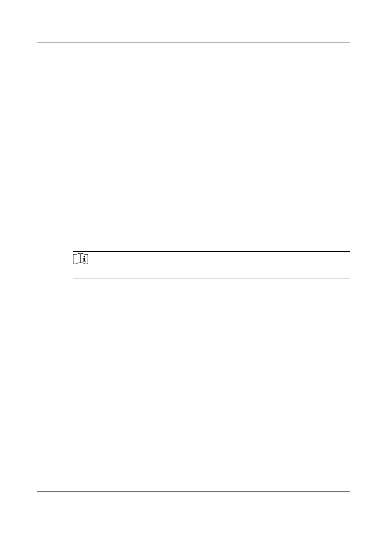
Must Check
The break duraon will be calculated and excluded from work hours according to actual
check-in and check-out me.
Return from Break Early for
The actual check-in and check-out me does not exceed the break me, and can be
marked as normal work or work overme.
Return from Break Late for
The actual check-in and check-out me exceeds the break me, and can be marked as
late, absent or early leave.
Calculated by
Each Check in/out: Each check-in me and check-out me is valid and the sum of all
periods between adjacent check-in and check-out me will be recorded as the break
me duraon.
First In & Last Out: The rst check-in me is recorded as start break me and the last
check-out me is recorded as the end break me.
Enable T&A Status
Set Enable T&A Status switch to on to calculate the actual break me according to
aendance status on the device.
Note
This funcon should be supported by the device.
Valid Authencaon Interval
During the valid authencaon interval, person swiping card for several mes will only
be calculated as once when calculang aendance data.
6.
Click Save to save the sengs.
7.
Oponal: Click Add to connue adding break me.
Congure Report Display
You can congure display contents displayed in the aendance report, such as the company name,
logo, date format, me format, and mark.
Steps
1.
Enter Time & Aendance module.
2.
Click Aendance Stascs → Report Display .
3.
Set the display sengs for aendance report.
Company Name
Enter a company name to display the name in the report.
Aendance Status Mark
DS-K1TA70 Series Face Recognion Terminal User Manual
173

Enter the mark and select the color. The related elds of aendance status in the report will
display with the mark and color.
Weekend Mark
Enter the mark and select the color. The weekend elds in the report will display with the
mark and color.
4.
Click Save.
9.11.2 Add General Timetable
On the metable page, you can add general metable for employees, which requires the xed
start-work me and end-work me. Also, you can set valid check-in/out me, allowable metable
for being late and leaving early.
Steps
1.
Click Time and Aendance → Timetable to enter the metable sengs page.
2.
Click Add to enter add metable page.
DS-K1TA70 Series Face Recognion Terminal User Manual
174
Figure 9-16 Add Timetable
3.
Create a name for the metable.
Note
You can click the color icon beside the name to customize the color for the valid metable on
the me bar in the Conguraon Result area.
4.
Select the metable type as general.
5.
Select calculaon method.
First In & Last Out
The rst check-in me is recorded as start work me and the last check-out me is recorded
as the end-work me.
Each Check-In/Out
Each check-in me and check-out me is valid and the sum of all periods between adjacent
check-in and check-out me will be recorded as the valid working duraon.
DS-K1TA70 Series Face Recognion Terminal User Manual
175

You need to set Valid Authencaon Interval for this calculaon method. For example, if the
interval between card swiping of the same card is less than the set value, the card swiping is
invalid.
6.
Oponal: Set Enable T&A Status switch to on to calculate according to aendance status of the
device.
Note
This funcon should be supported by the device.
7.
Oponal: Enable Calculate Break Time into Aended Duraon.
Note
When enabled, break me will be calculated into the overall aendance duraon. That is, the
actual aendance duraon equals to the overall aendance duraon (includes break me).
8.
Set the related aendance me parameters as the following:
Start/End-Work Time
Set the start-work me and end-work-me.
Valid Check-in/out Time
On the me bar, adjust the yellow bar to set the metable during which the check-in or
check-out is valid.
Calculated as
Set the duraon calculated as the actual work duraon.
Late/Early Leave Allowable
Set the metable for late or early leave.
9.
Set absence related parameters.
Check-In, Late for
You can set the late me duraon for the employee who has checked in but is late for work. If
the employee exceeds the required me period, his/her aendance data will be marked as
absent.
Check-Out, Early Leave for
You can set the early leave me duraon for the employee who checks out earlier than the
normal leave me, and his/her aendance data will be marked as absent.
No Check-in
If the employee does not check in, his/her aendance data may be marked as absent or late.
No Check-Out
If the employee does not check out, his/her aendance data may be marked as absent or
early leave.
10.
Click Save to add the metable.
11.
Oponal: Perform one or more following operaons aer adding metable.
Edit Timetable Select a metable from the list to edit related informaon.
DS-K1TA70 Series Face Recognion Terminal User Manual
176

Delete Timetable Select a metable from the list and click Delete to delete it.
9.11.3 Add Shi
You can add shi for employees including seng shi period (day, week, month) and the eecve
aendance me. According to the actual requirements, you can adding mulple metables in one
shi for employees, which requires them to check in and check out for each metable.
Before You Start
Add a metable rst. See
Add General Timetable for details.
Steps
1.
Click Time & Aendance → Shi to enter shi sengs page.
2.
Click Add to enter Add Shi page.
3.
Enter the name for shi.
4.
Select the shi period from the drop-down list.
5.
Select the added metable and click on the me bar to apply the metable.
DS-K1TA70 Series Face Recognion Terminal User Manual
177

Figure 9-17 Add Shi
Note
You can select more than one metables. The start and end work me and the valid check-in
and out me in dierent me tables can not be overlapped.
DS-K1TA70 Series Face Recognion Terminal User Manual
178
Figure 9-18 Add Mulple Timetables
6.
Click Save.
The added shi lists on the le panel of the page. At most 64 shis can be added.
7.
Oponal: Assign the shi to organizaon or person for a quick shi schedule.
1) Click Assign.
2) Select Organizaon or Person tab and check the desired organizaon(s) or person(s) box.
The selected organizaons or persons will list on the right page.
3) Set the Expire Date for the shi schedule.
4) Set other parameters for the schedule.
Check-in Not Required
Persons in this schedule do not need to check-in when they come to work.
Check-out Not Required
Persons in this schedule do not need to check-out when they end work.
Scheduled on Holidays
DS-K1TA70 Series Face Recognion Terminal User Manual
179
On the holidays, this schedule is sll eecve and the persons needs to go to work
according to the schedule.
Eecve for Overme
The persons' overme will be recorded for this schedule.
5) Click Save to save the quick shi schedule.
9.11.4 Manage Shi Schedule
Shi work is an employment pracce designed to make use of all 24 hours of the clock each day of
the week. The pracce typically sees the day divided into shis, set periods of me during which
dierent shis perform their dues.
You can set department schedule, person schedule, and temporary schedule.
Set Department Schedule
You can set the shi schedule for one department, and all the persons in the department will be
assigned with the shi schedule.
Before You Start
In Time & Aendance module, the department list is the same with the organizaon. You should
add organizaon and persons in Person module rst. See Person Management for details.
Steps
1.
Click Time & Aendance → Shi Schedule to enter the Shi Schedule Management page.
2.
Click Department Schedule to enter Department Schedule page.
3.
Select the department from the organizaon list on the le.
Note
If Include Sub Organizaon is checked, when selecng the organizaon, its sub organizaons are
selected at the same me.
4.
Select the shi from the drop-down list.
5.
Oponal: Enable Mulple Shi Schedules and select the eecve me period(s) from the
added metables for the persons.
Note
This is only available for shi with only one metable.
Mulple Shi Schedules
It contains more than one metables. The person can check in/out in any of the metables
and the aendance will be eecve.
DS-K1TA70 Series Face Recognion Terminal User Manual
180

If the mulple shi schedules contains three metables: 00:00 to 07:00, 08:00 to 15:00 and
16:00 to 23:00. The aendance of the person adopng this mulple shi schedules will be
eecve in any of the three metables. If the person checks in at 07:50, it will apply the
nearest metable 08:00 to 15:00 to the person's aendance.
6.
Set the start date and end date.
7.
Set other parameters for the schedule.
Check-in Not Required
Persons in this schedule do not need to check-in when they come to work.
Check-out Not Required
Persons in this schedule do not need to check-out when they end work.
Scheduled on Holidays
On the holidays, this schedule is sll eecve and the persons needs to go to work according
to the schedule.
Eecve for Overme
The persons' overme will be recorded for this schedule.
Flexible Shi Schedule on Weekend
The person's aendance on the weekend will be recorded as overme.
8.
Click Save.
Set Person Schedule
You can assign the shi schedule to one or more persons. You can also view and edit the person
schedule details.
Before You Start
Add department and person in Person module. See
Person Management for details.
Steps
Note
The person schedule has the higher priority than department schedule.
1.
Click Time & Aendance → Shi Schedule to enter the Shi Schedule page.
2.
Click Person Schedule to enter Person Schedule page.
3.
Select the organizaon and select the person(s).
4.
Select the shi from the drop-down list.
5.
Oponal: Enable Mulple Shi Schedules and select the eecve me period(s) from the
added metables for the persons.
DS-K1TA70 Series Face Recognion Terminal User Manual
181
Note
This is only available for shi with only one metable.
Mulple Shi Schedules
It contains more than one metables. The person can check in/out in any of the metables
and the aendance will be eecve.
If the mulple shi schedules contains three metables: 00:00 to 07:00, 08:00 to 15:00 and
16:00 to 23:00. The aendance of the person adopng this mulple shi schedules will be
eecve in any of the three metables. If the person checks in at 07:50, it will apply the
nearest metable 08:00 to 15:00 to the person's aendance.
6.
Set the start date and end date.
7.
Set other parameters for the schedule.
Check-in Not Required
Persons in this schedule do not need to check-in when they come to work.
Check-out Not Required
Persons in this schedule do not need to check-out when they end work.
Scheduled on Holidays
On the holidays, this schedule is sll eecve and the persons needs to go to work according
to the schedule.
Eecve for Overme
The persons' overme will be recorded for this schedule.
Flexible Shi Schedule on Weekend
The person's aendance on the weekend will be recorded as overme.
8.
Click Save.
Set Temporary Schedule
You can add a temporary schedule for the person and the person will be assigned with the shi
schedule temporarily. You can also view and edit the temporary schedule details.
Before You Start
Add department and person in Person module. See
Person Management for details.
Steps
Note
The temporary schedule has higher priority than department schedule and person schedule.
1.
Click Time & Aendance → Shi Schedule to enter the Shi Schedule Management page.
2.
Click Temporary Schedule to enter Temporary Schedule page.
3.
Select the organizaon and select the person(s).
DS-K1TA70 Series Face Recognion Terminal User Manual
182

4.
Click one date or click and drag to select mulple dates for the temporary schedule.
5.
Select Workday or Non-Workday from drop-down list.
If Non-Workday is selected, you need to set the following parameters.
Calculated as
Select normal or overme level to mark the aendance status for temporary schedule.
Timetable
Select a metable from drop-down list.
Mulple Shi Schedule
It contains more than one metables. The person can check in/out in any of the metables
and the aendance will be eecve.
If the mulple shi schedules contains three metables: 00:00 to 07:00, 08:00 to 15:00 and
16:00 to 23:00. The aendance of the person adopng this mulple shi schedules will be
eecve in any of the three metables. If the person checks in at 07:50, it will apply the
nearest metable 08:00 to 15:00 to the person's aendance.
Rule
Set other rule for the schedule, such as Check-in Not Required, andCheck-out Not Required.
6.
Click Save.
Check Shi Schedule
You can check the shi schedule in calendar or list mode. You ca also edit or delete the shi
schedule.
Steps
1.
Click Time & Aendance → Shi Schedule to enter the Shi Schedule Management page.
2.
Select the organizaon and corresponding person(s).
3.
Click
or to view the shi schedule in calendar or list mode.
Calendar
In calendar mode, you can view the shi schedule for each day in one month. You can click
the temporary schedule for one day to edit or delete it.
List
In list mode, you can view the shi schedule details about one person or organizaon, such as
shi name, type, eecve period and so on. Check the shi schedule(s), and click Delete to
delete the selected shi schedule(s).
9.11.5 Manually Correct Check-in/out Record
If the aendance status is not correct, you can manually correct the check-in or check out record.
You can also edit, delete, and export the check-in or check-out record.
DS-K1TA70 Series Face Recognion Terminal User Manual
183
Before You Start
●
You should add organizaons and persons in Person module. For details, refer to Person
Management .
●
The person's aendance status is incorrect.
Steps
1.
Click Time & Aendance → Aendance Handling to enter aendance handling page.
2.
Click Correct Check-in/out to enter adding check-in/out correcon page.
3.
Select one or more persons from le list for correcon.
4.
Select the correcon date.
5.
Select the correcon type as Check-in, Check-out, Break-in, Break-out, etc,. and set the correct
me.
Note
You can click to add mulple correcon items. At most 8 check-in/out items can be added.
6.
Oponal: Enter the remark informaon as desired.
7.
Click Save to save the above sengs.
8.
Oponal: Aer adding the check-in/out correcon, perform one of the following operaons.
View Click
or to view the added aendance handling informaon in calendar or list
mode.
Edit
●
In calendar mode, click
→ Edit to edit the details.
●
In list mode, double-click the related eld in Date, Handling Type, Time, or Remark
column to edit the details.
Note
The edited check-in/out correcon will take aect.
Delete
●
In calendar mode, select one check-in/out correcon, and click Delete to delete
the selected item.
●
In list mode, check one or more check-in/out correcons, and click Delete to
delete the selected items.
Note
The deleted check-in/out correcon will no longer take aect.
Export In list mode, check one or more check-in/out correcons to export the aendance
handling details (CSV le) to local PC.
9.11.6 Add Leave and Business Trip
You can add leave and business trip when the employee want to ask for leave or go on a business
trip.
DS-K1TA70 Series Face Recognion Terminal User Manual
184
Before You Start
You should add organizaons and persons in the Person module. For details, refer to Person
Management .
Steps
1.
Click Time & Aendance → Aendance Handling to enter aendance handling page.
2.
Click Apply for Leave/Business Trip to enter adding the leave/business trip page.
3.
Select person from le list.
4.
Set the date(s) for your leave or business trip.
5.
Select the major leave type and minor leave type from the drop-down list.
Note
You can set the leave type in Aendance Sengs. For details, refer to Congure Leave Type .
6.
Set the me for leave.
7.
Oponal: Enter the remark informaon as desired.
8.
Click Save.
9.
Oponal: Aer adding the leave and business trip, perform one of the following operaons.
View Click
or to view the added aendance handling informaon in calendar or list
mode.
Note
In calendar mode, you need to click Calculate to get the aendance status of the
person in one month.
Edit
●
In calendar mode, click the related label on date to edit the details.
●
In list mode, double-click the led in Date, Handling Type, Time, or Remark column
to edit the related informaon.
Delete Delete the selected items.
Export Export the aendance handling details to local PC.
Note
The exported details are saved in CSV format.
9.11.7 Calculate Aendance Data
You need to calculate the aendance data before searching and viewing the overview of the
aendance data, employees' detailed aendance data, employees' abnormal aendance data, the
employees' overme working data, and card swiping log.
DS-K1TA70 Series Face Recognion Terminal User Manual
185
Automacally Calculate Aendance Data
You can set a schedule so that the client can automacally calculate aendance data of the
previous day at the me you congured every day.
Steps
Note
1.
Enter the Time & Aendance module.
2.
Click Aendance Sengs → General Rule .
3.
In the Auto-Calculate Aendance area, set the me that you want the client to calculate the
data.
4.
Click Save.
The client will calculate the aendance data of the previous day from the me you have
congured.
Manually Calculate Aendance Data
You can manually calculate aendance data by seng condions including aendance me,
department, aendance status, etc.
Steps
1.
Enter the Time & Aendance module.
2.
Click Aendance Stascs → Calculaon .
3.
Set the start me and end me to dene the aendance data range.
4.
Select the department from the drop-down list.
5.
Oponal: Set other condions, including name and person ID.
6.
Check aendance status (supports mul-selecon).
7.
Click Calculate.
Note
Only the aendance data within three months can be calculated.
8.
Oponal: Perform one of the following operaons.
Correct Check-
in/out
Select one person, click Correct Check-in/out to add check-in/out
correcon.
Select Items to
Display
Click
on the upper right corner, or right click the table header of the
aendance data list to customize the items to be displayed in the list.
Adjust Items
Sequence
Click one item (except Person ID) and move the mouse to customize the
sequence of dierent items.
Generate Report Click Report to generate the aendance report.
DS-K1TA70 Series Face Recognion Terminal User Manual
186
Note
The report items will be displayed in the sequence you have set.
Export Report Click Export to export aendance data (CSV le) to local PC.
Note
The report items will be displayed in the sequence you have set.
9.11.8 Aendance Stascs
You can check the original aendance record, generate and export the aendance report based on
the calculated aendance data.
Get an Overview of Employees' Aendance Data
You can search and view the employee's aendance data on the client, including aendance me,
aendance status, check point, etc.
Before You Start
●
You should add organizaons and persons in Person module and the persons have swiped cards.
For details, refer to Person Management .
●
Calculate the aendance data.
Note
○
The client will automacally calculate the previous day's aendance data at 1:00 am on the
next day.
○
Keep the client running at 1:00 am or it cannot calculate the previous day's aendance data
automacally. If not calculated automacally, you can calculate the aendance data manually.
For details, refer to Manually Calculate Aendance Data .
Steps
1.
Enter the Time & Aendance module.
2.
Click Aendance Stascs → Aendance Record .
3.
Set the aendance start me and end me that you want to search.
4.
Set other search condions, including department, name, and person ID.
5.
Select data source as All, Original Records on Device or Manually Handled Records.
6.
Oponal: Click Get Events from Device to get the aendance data from the device.
Note
There are two methods for geng aendance events from the device, including Online and
Import File. For more details about operaons, refer to .
DS-K1TA70 Series Face Recognion Terminal User Manual
187
7.
Oponal: Click Reset to reset all the search condions and edit the search condions again.
8.
Click Search.
9.
Oponal: For the displayed search results, perform one of the following operaons.
Edit Aendance
Status
Select one incorrect record, double click the eld of Aendance Status
column and select from the drop-down list to edit single piece of
aendance status.
Check two or more incorrect records, click Edit Aendance Status on the
upper le corner and select from the drop-down list to batch edit mulple
pieces of aendance status.
Generate Report Click Report to generate the aendance report.
Export Report Click Export and select saving path to export the aendance report (CVS
le) to the local PC.
Custom Export Click Custom Report and set condions to export aendance records
according to actual needs. For details, refer to .
Generate Instant Report
It supports to generate the a series of aendance reports manually to view the employees'
aendance results.
Before You Start
Calculate the aendance data.
Note
You can calculate the aendance data manually, or set the schedule so that the client can calculate
the data automacally every day. For details, refer to Calculate Aendance Data .
Steps
1.
Enter the Time & Aendance module.
2.
Click Aendance Stascs → Report .
3.
Select a report type.
4.
Select the department or person to view the aendance report.
5.
Set the start me and end me during which the aendance data will be displayed in the report.
6.
Click Report to generate the stascs report and open it.
Send Report Regularly
The client supports mulple report types and you can pre-dene the report content and it can
send the report automacally to the email address you congured.
DS-K1TA70 Series Face Recognion Terminal User Manual
188
Steps
1.
Enter the Time & Aendance module.
2.
Click Aendance Stascs → Regularly Send Report .
3.
Click Add to enter the add custom report page.
4.
Set the report content.
Report Name
Enter a name for the report.
Report Type
Select one report type and this report will be generated.
Report Time
The me to be selected may vary for dierent report type.
Person
Select the added person(s) whose aendance records will be generated for the report.
Note
You can view the selected person(s) in the right side of the Person area.
5.
Set the schedule to send the report to the email address(es) automacally.
Note
The Auto-Send Email funcon is enabled by default.
1) Set the Eecve Period during which the client will send the report on the selected sending
date(s).
2) Select the Sending Date(s) on which the client will send the report.
3) Set the Sending Time at which the client will send the report.
Example
If you set the eecve period as 2018/3/10 to 2018/4/10, select Friday as the sending date,
and set the sending me as 20:00:00, the client will send the report at 8 p.m. on Fridays
during 2018/3/10 to 2018/4/10.
Note
Make sure the aendance records are calculated before the sending me. You can calculate
the aendance data manually, or set the schedule so that the client can calculate the data
automacally every day. For details, refer to Calculate Aendance Data .
4) Enter the receiver email address(es).
Note
Up to 5 email addresses can be added. You can click + to add a new email address.
5) Oponal: Click Preview to view the email details.
6.
Click OK.
DS-K1TA70 Series Face Recognion Terminal User Manual
189

7.
Oponal: Aer adding the custom report, you can do one or more of the followings:
Edit Report Select one added report and click Edit to edit its sengs.
Delete Report Select one added report and click Delete to delete it.
Generate Report Select one added report and click Report to generate the report instantly
and you can view the report details.
9.12 System Conguraon
9.12.1 Set General Parameters
You can congure the frequently-used parameters, including log expired me, network
performance, etc.
Steps
1.
Enter the System Conguraon module.
2.
Click General tab to enter the General Sengs page.
3.
Congure the general parameters.
Date Format / Time Format
The display style of date and me on related pages.
Log Expiry Date
The me for keeping the log les. Once exceeded, the les will be deleted.
Maximum Mode
Select Maximize or Full Screen as the maximum mode. Maximize mode can maximize the
display and show the taskbar. Full Screen mode can display the client in full-screen mode.
Calendar Type
Select Gregorian Calendar or Nepali Calendar as the calendar type. If you select Nepali
Calendar, the calender will switch to Nepali language and calculated me by Nepali calendar.
You need to restart the client aer switching the calendar.
Network Performance
Set the network condions to Normal, Beer or Best.
Save Pictures in Structure Data Format
You can enable Save Pictures in Structure Data Format to save structure data and delete
registered picture.
Save Event for
Set the event deleng cycle to delete the old event.
Detect New Soware Version
DS-K1TA70 Series Face Recognion Terminal User Manual
190

Aer enabled, the client can automacally detect the new soware version and remind the
user to upgrade the soware.
Automac Time Synchronizaon
Automacally synchronize the me of the added devices with the me of the PC running the
client at a specied me point.
Auto-Upgrade Device
Set the upgrading mode aer the new version of device are detected.
Disable
Aer enabled, the client will not download the rmware package and upgrade even if the
client detects a new version of the client.
Prompt Me If Download and Upgrade
Aer the client detects a new version of the device, it will prompt the user whether to
download the rmware package and upgrade.
Download and Prompt Me If Upgrade
Aer the client detects the new version of the device, it will download the rmware
package automacally, and prompt the user whether to upgrade.
Download and Prompt Automacally
Aer the client detects the new version of the devices, it will download the rmware
package and upgrade the new version automacally.
You need to set a schedule in the Upgrade Time eld, during which the client upgrades the
new version automacally.
4.
Click Save.
9.12.2 Set Picture Storage
The pictures, captured by the camera of video access control terminal, triggered by events, can be
saved in the PC running the iVMS-4200 Service. You can set the picture storage locaon here
manually.
Steps
1.
Enter the System Conguraon module.
2.
Click Event Picture Storage.
3.
Set the Store Pictures in Server switch to on.
All the disks of the PC running the iVMS-4200 service will show.
4.
Select the disk to save the pictures.
Note
The default saving path is: Disk/iVMS-4200alarmPicture
5.
Click Save.
DS-K1TA70 Series Face Recognion Terminal User Manual
191
9.12.3 Set Alarm Sound
When the event is triggered, the client can give an audible warning to nofy the security
personnel. You can set the sound of the audible warning in this secon.
Steps
1.
Open the System Conguraon page.
2.
Click Alarm Sound tab to enter the Alarm Sound Sengs page.
3.
Oponal: Click and select the audio les from the local path for dierent events.
4.
Oponal: Add customized alarm sound.
1) Click Add to add customized alarm sound.
2) Double click the Type eld to customize the alarm sound name as desired.
3) Click and select the audio les from the local path for dierent alarms.
5.
Oponal: Click for a tesng of the audio le.
6.
Oponal: Click in the Operaon column to delete the custom sound.
7.
Click Save.
Note
The format of the audio le can only be WAV.
9.12.4 Set Access Control and Video Intercom Parameters
You can congure the access control and video intercom parameters according to actual needs.
Steps
1.
Open the System Conguraon page.
2.
Click the Access Control & Video Intercom tab.
3.
Input the required informaon.
Ringtone
Click
and select the audio le from the local path for the ringtone of indoor staon.
Oponally, you can click for a tesng of the audio le.
Max. Ring Duraon
Specify the seconds that the ring will last for at most. The maximum ring duraon can be set
from 15s to 60s.
Max. Speaking Duraon with Indoor Staon
Specify the seconds that the call with indoor staon will last for at most. The maximum
speaking duraon between indoor staon and the client can be set from 120s to 600s.
Max. Speaking Duraon with Door Staon
Specify the seconds that the call with door staon will last for at most. The maximum
speaking duraon between door staon and the client can be set from 90s to 120s.
DS-K1TA70 Series Face Recognion Terminal User Manual
192

Max. Speaking Duraon with Access Control Device
Specify the seconds that the call with access control device will last for at most. The
maximum speaking duraon between access control device and the client can be set from
90s to 120s.
4.
Click Save.
9.12.5 Set File Saving Path
The pictures captured in Status Monitoring module are stored on the local PC. The saving path of
these les can be set.
Steps
1.
Open the System Conguraon page.
2.
Click File tab to enter the File Saving Path Sengs page.
3.
Click and select a local path for the les.
4.
Click Save.
9.12.6 Set Email Parameters
When an event is triggered, if you can set Send Email as linkage acon for this event, the client will
an email to the recipients for nocaon. You need to set the email sengs and specify target
recipients in this secon.
Steps
1.
Enter the System Conguraon module.
2.
Click Email tab to enter the Email Sengs interface.
3.
Enter the required informaon.
STMP Server
The STMP server IP address of host name (e.g., smtp.263xmail.com)
Encrypon Type
You can check the radio to select Non-Encrypted, SSL, or STARTTLS .
Port
Enter the communicaon port used for SMTP. The port is 25 by default.
Sender Address
The email address of the sender.
Security Cercate (Oponal)
If your email server requires authencaon, check this checkbox to use authencaon to log
into the server and enter the login user name and password of your email account.
User Name
DS-K1TA70 Series Face Recognion Terminal User Manual
193

Enter the user name of the sender email address if Server Authencaon is checked.
Password
Enter the password of the sender Email address if Server Authencaon is checked.
Receiver 1 to 3
Enter the email address of the receiver. Up to 3 receivers can be set.
4.
Oponal: Click Send Test Email to send an email to the receiver for test.
5.
Click Save.
9.13 Operaon and Maintenance
You can perform maintaining operaons in the menu to ensure a smooth and convenient usage of
the client.
In the upper-right corner of the client, click
→ File → System → Tool , and perform the
following operaons.
Open Log File
You can open a log le saved in your local PC or log les of the client.
Import/Export Conguraon File
You can import conguraon les from local PC to the client if needed, and vice versa.
Auto Backup
Select day and me to backup conguraon les and data in database, or restore the backed up
data.
Skin
Change the skin of the client, including bright-color series and black-color series.
Batch Time Sync
Synchronize selected devices' me with your PC me.
Message Queue
Aer conguring email linkage, the triggered event(s) will be displayed here. Select an event and
cancel sending the an email to the receiver.
9.14 Remote Conguraon (Web)
Congure device parameters remotely.
DS-K1TA70 Series Face Recognion Terminal User Manual
194
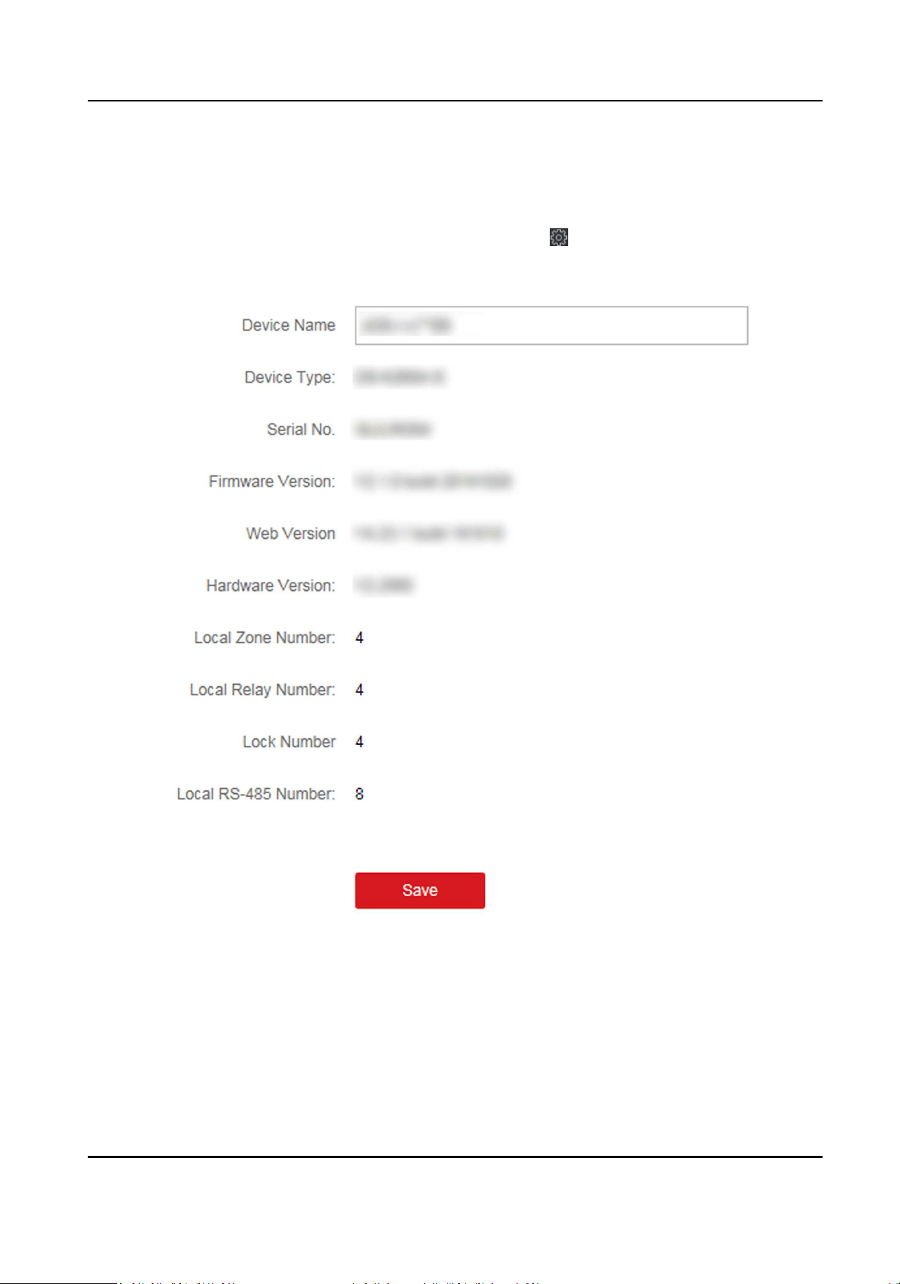
9.14.1 View Device Informaon
View and set device name, view device type, serial No., version, relay number, and lock number.
Select a device from the Device for Management tab and click → System → Device Informaon
to enter the Device Informaon page.
Figure 9-20 View Device Informaon
You can set the device name, view the device type, serial No., version, relay number, and lock
number. Click Save to save the sengs.
DS-K1TA70 Series Face Recognion Terminal User Manual
195
9.14.2 Change Device Password
You can change the device password.
Before You Start
Make sure the device is acvated. For details, see Acvaon.
Steps
1.
On the Device for Management page, click → System → User to enter the User tab.
2.
Select a user and click Edit to enter the Edit page.
3.
Input the old password, create a new password, and conrm the new password.
Cauon
The password strength of the device can be automacally checked. We highly recommend you
change the password of your own choosing (using a minimum of 8 characters, including at least
three kinds of following categories: upper case leers, lower case leers, numbers, and special
characters) in order to increase the security of your product. And we recommend you change
your password regularly, especially in the high security system, changing the password monthly
or weekly can beer protect your product.
Proper conguraon of all passwords and other security sengs is the responsibility of the
installer and/or end-user.
4.
Click OK.
Result
The device password is changed. You should enter the new password on the Device for
Management page to reconnect the device.
9.14.3 Time Management
Manage device's me zone, me synchronizaon, and DST parameters.
Time Zone and Time Synchronizaon
On the Device for Management page, select a device and click
→ System → Time to enter the
Time tab.
You can select a me zone, set NTP parameters, or manually synchronize me.
Time Zone
Select a me zone from the drop-down list.
NTP
The device will synchronize me with NTP automacally. Aer you enable NTP, you should set
the NTP server address, NTP port, and synchronizaon interval.
Manual Time Synchronizaon
DS-K1TA70 Series Face Recognion Terminal User Manual
196

Aer you enable Manual Time Synchronizaon, you can manually set the device me.
If you check Synchronize with Computer Time, the Set Time will display the current computer's
me. At this me, uncheck Synchronize with Computer Time, and click , you can edit the
device me manually.
Click Save to save the sengs.
DST
On the Device for Management page, click Remote Conguraon → System → Time → DST to
enter the DST tab.
Enable DST and you can edit the DST bias me, the DST start me, and end me.
Click Save.
9.14.4 System Maintenance
You can reboot the device remotely, restore the device to default sengs, import conguraon
le, upgrade the device, etc.
Reboot
On the Device for Management page, click → System → System Maintenance to enter the
System Maintenance tab.
Click Reboot and the device starts reboong.
Restore Sengs
On the Device for Management page, click Remote Conguraon → System → System
Maintenance to enter the System Maintenance tab.
Restore Default
The parameters will be restored the default ones, excluding the IP address.
Restore Part of Sengs
Restore all sengs except communicaon sengs and the remote user sengs to default ones.
Restore All
All device parameters will be restored to the default ones. The device should be acvated aer
restoring.
Import and Export
On the Device for Management page, click Remote Conguraon → System → System
Maintenance to enter the System Maintenance tab.
Import or export conguraon le.
Import Conguraon File
Import the conguraon le from the local PC to the device.
DS-K1TA70 Series Face Recognion Terminal User Manual
197
Note
The conguraon le contains the device parameters.
Export Conguraon File
Export the conguraon le from the device to the local PC.
Note
The conguraon le contains the device parameters.
Upgrade
On the Device for Management page, click Remote Conguraon → System → System
Maintenance to enter the System Maintenance tab.
Select a device type from the drop-down list, click Browse and select an upgrade le from the local
computer, and click Upgrade.
Note
●
If you select Card reader as the device type, you should also select a card reader No. from the
drop-down list.
●
The upgrade will lasts for about 2 min. Do not power o during the upgrading. Aer upgrading,
the device will reboot automacally.
9.14.5 Congure RS-485 Parameters
You can set the RS-485 parameters including the baud rate, data bit, stop bit, parity type,
communicaon mode, work mode, and connecon mode.
Steps
1.
Click Maintenance and Management → Device to enter the device list.
2.
Click to enter the remote conguraon page.
3.
Click System → RS-485 Sengs to enter the Conguring the RS-485 Parameters tab.
4.
Select the serial No. of the port from the drop-down list to set the RS-485 parameters.
5.
Set the baud rate, data bit, the stop bit, parity, ow control, communicaon mode, working
mode, and the connecon mode from the drop-down list.
6.
Click Save and the congured parameters will be applied to the device automacally.
Note
Aer changing the working mode, the device will be rebooted. A prompt will be popped up aer
changing the working mode.
DS-K1TA70 Series Face Recognion Terminal User Manual
198

9.14.6 Security Mode Sengs
Set the security mode for logging in the client soware.
On the Device for Management page, click → System → Security to enter the Security Mode
tab.
Select a security mode from the drop-down list, and click Save.
You can also enable SSH to get a more secure network.
Security Mode
High security level for user informaon vericaon when logging in the client soware.
Compable Mode
The user informaon vericaon is compable with the old client soware version when
logging in.
9.14.7 Network Parameters Sengs
Set device network parameters, including the NIC type, DHCP, and HTTP.
On the Device for Management page, click → Network → Network Parameters to enter the
Network Parameters Sengs tab.
NIC Type
Select a NIC type from the drop-down list. You can select either Self-adapve, 10M, or 100M.
DHCP
If you disable the funcon, you should manually set the device's IPv4 address, IPv4 subnet
mask, IPv4 default gateway, MTU, and port.
If you enable the funcon, the system will automacally assign IPv4 address, IPv4 subnet mask,
IPv4 default gateway for the device.
HTTP
Set the HTTP port, DNS1 server address, and DNS2 server address.
9.14.8 Report Strategy Sengs
You can set the center group for uploading the log via the EHome protocol.
On the Device for Management page, click → Network → Report Strategy to enter the Report
Strategy Sengs tab.
You can set the center group and the system will transfer logs via EHome protocol. Click Save to
save the sengs.
Center Group
Select a center group from the drop-down list.
DS-K1TA70 Series Face Recognion Terminal User Manual
199
Main Channel
The device will communicate with the center via the main channel.
Note
N1 refers to wired network.
9.14.9 Network Center Parameters Sengs
You can set the nofy center, center's IP address, the port No., the protocol (EHome), the EHome
account user name,etc. to transmit data via EHome protocol.
On the Device for Management page, click → Network → Network Center Parameters to enter
the Network Center Parameters Sengs tab.
Select a center from the drop-down list.
Aer enabling the funcon, you can set the center's address type, IP address/domain name, port
No., EHome user name, etc.
Click Save.
9.14.10 Congure SIP Parameters
Set the main staon's IP address and the SIP server's IP address. Aer seng the parameters, you
can communicate among the access control device, door staon, indoor staon, main staon, and
the plaorm.
Note
Only the access control device and other devices or systems (such as door staon, indoor staon,
main staon, plaorm) are in the same IP segment, the two-way audio can be performed.
Click Maintenance and Management → Device to enter the device list.
Click to enter the remote conguraon page.
Click Network → Linked Network Conguraon and set the main staon's IP address and SIP
server's IP address.
Click Save.
9.14.11 Set Relay Parameters
Click Maintenance and Management → Device to enter the device list.
Click to enter the remote conguraon page.
Click Alarm → Relay . Select a relay and click and set the relay name and output delay me.
Click OK to save the sengs.
DS-K1TA70 Series Face Recognion Terminal User Manual
200

9.14.12 Set Access Control Parameters
Steps
1.
On the Device for Management page, click → Others → Access Control Parameters to enter
the Access Control Parameters tab.
2.
Check the checkbox to enable the funcon.
Audio Prompt (Voice Prompt)
If you enable this funcon, the voice prompt is enabled in the device. You can hear the voice
prompt when operang in the device.
Upload Pictures aer Capturing
If you enable this funcon, the captured pictures will be sent to the client soware.
Save Captured Pictures
If you enable this funcon, the captured pictures will be saved.
Temperature Measurement Only
When enabling the funcon, the device will not authencate the permissions, but only take
the temperature. When disabling the funcon, the device will authencate the permissions
and at the same me take the temperature.
Capture White Light Picture
When enabling the funcon, the pictures captured by the white light camera will be uploaded
to the plaorm. If disabling the funcon, the device will only upload pictures captured by
thermographic camera to the plaorm.
Door Not Open When Detecng Abnormal Temperature
When enabling the funcon, the door will not open when the detected temperature is higher
or lower than the congured temperature threshold. By default, the temperature is enabled.
Must Wear Face Mask
Aer enabling this funcon, the authencated person must wear a face mask, otherwise the
authencaon will be failed.
Over-Temperature Alarm
Edit the threshold according to actual situaon. If the detected temperature is higher than
the congured parameters, an alarm will be triggered. The value should be between 35.1 ℃
and 44.9 ℃.
3.
Click Save.
9.14.13 Set Face Recognion Terminal Parameters
Click Maintenance and Management → Device to enter the device list.
Press CTRL and click
to enter the remote conguraon page.
DS-K1TA70 Series Face Recognion Terminal User Manual
201

Click Other → Face Recognion Terminal Parameters and you can congure the device
parameters.
Face Picture Database
Select Deep Learning as the face picture database.
Save Authencang Face Picture
If enabled, the captured face picture when authencang will be saved on the device.
CPU Card Reading
Select to read card No. or le.
Work Mode
Set the device work mode as Normal Mode. You should authencate your credenal for
accessing.
ECO Mode
Aer enabling the ECO mode, the device will use the IR camera to authencate faces in the low
light or dark environment. And you can set he ECO mode threshold, ECO mode (1:N), and ECO
mode (1:1).
ECO Mode (1:1)
Set the matching threshold when authencang via ECO mode 1:1 matching mode. The larger
the value, the smaller the false accept rate and the larger the false rejecon rate.
ECO Mode (1:N)
Set the matching threshold when authencang via ECO mode 1:N matching mode. The larger
the value, the smaller the false accept rate and the larger the false rejecon rate.
ECO Mode Threshold
When enabling the ECO mode, you can set the ECO mode’s threshold. The larger the value, the
easier the device entering the ECO mode. Available range: 0 to 8.
Click Save to save the sengs.
9.14.14 Congure Face Picture Parameters
Steps
1.
Click Maintenance and Management → Device to enter the device list.
2.
Click to enter the remote conguraon page.
3.
Click Other → Face Picture Parameters to enter the Conguring Face Picture Parameters page.
Pitch Angle
The maximum pitch angle when face authencaon.
Yaw Angle
The maximum yaw angle when face authencaon.
Margin (Le)
DS-K1TA70 Series Face Recognion Terminal User Manual
202

The distance percentage from the face le side to the le margin in the recognion area.
The actual distance percentage should be larger than the congured value when face picture
authencaon. Other percentages, distances, and angles should also meet their condions.
Margin (Right)
The distance percentage from the face right side to the right margin in the recognion area.
The actual distance percentage should be larger than the congured value when face picture
authencaon. Other percentages, distances, and angles should also meet their condions.
Margin (Top)
The distance percentage from the face top side to the top margin in the recognion area.
The actual distance percentage should be larger than the congured value when face picture
authencaon. Other percentages, distances, and angles should also meet their condions.
Margin (Boom)
The distance percentage from the face boom side to the boom margin in the recognion
area.
The actual distance percentage should be larger than the congured value when face picture
authencaon. Other percentages, distances, and angles should also meet their condions.
Pupillary Distance
The minimum resoluon between two pupils when face recognion.
The actual resoluon should be larger than the congured value.
Score
The device will score the captured picture according to the yaw angle, pitch angle, and
pupillary distance. If the score is less than the congured value, face recognion will be failed.
You can set the face picture parameters when authencang.
4.
Click Save.
9.14.15 Congure Supplement Light Parameters
You can turn on or o the supplement light. You can also adjust the supplement light brightness.
Steps
1.
Click Maintenance and Management → Device to enter the device list.
2.
Click
to enter the remote conguraon page.
3.
Click Other → Supplement Light Parameters to enter the Conguring Supplement Light
Parameters page.
4.
Select a supplement light type from the drop-down list.
5.
Select a supplement light mode from the drop-down list.
6.
Oponal: Set the supplement light brightness.
7.
Click Save to save the sengs.
DS-K1TA70 Series Face Recognion Terminal User Manual
203

9.14.16 Set Device No.
Set the device type, community No., building No., oor No., and unit No., and room No.
Click Maintenance and Management → Device to enter the device list.
Click to enter the remote conguraon page.
Click Other → No. Sengs and Set the device type, community No., building No., oor No., and
unit No., and No.
9.14.17 Congure Video and Audio Parameters
You can set the device camera's image quality, resoluon and other parameters.
Steps
1.
Click Maintenance and Management → Device to enter the device list.
2.
Click to enter the remote conguraon page.
3.
Click Image → Video & Audio to enter the sengs page.
4.
Set the device camera's parameters, including the stream type, the bitrate type, the video
quality, the frame rate, the audio encoding type, the video type, the bitrate, the resoluon, and
the I frame interval.
5.
Click Save.
9.14.18 Congure Volume Input or Output
Steps
1.
On the Device for Management page, click → Image → Audio Input or Output to enter Audio
Input or Output tab.
2.
Move the block to adjust the device input and output volume.
3.
Click Save.
9.14.19 Operate Relay
Steps
1.
Click Maintenance and Management → Device to enter the device list.
2.
Click to enter the remote conguraon page.
3.
Click Operaon → Relay .
4.
Enable or disable the relay.
9.14.20 View Relay Status
Click Maintenance and Management → Device Management → Device to enter the device list.
DS-K1TA70 Series Face Recognion Terminal User Manual
204

Click to enter the remote conguraon page.
Click Status → Relay and you can view the relay status.
DS-K1TA70 Series Face Recognion Terminal User Manual
205
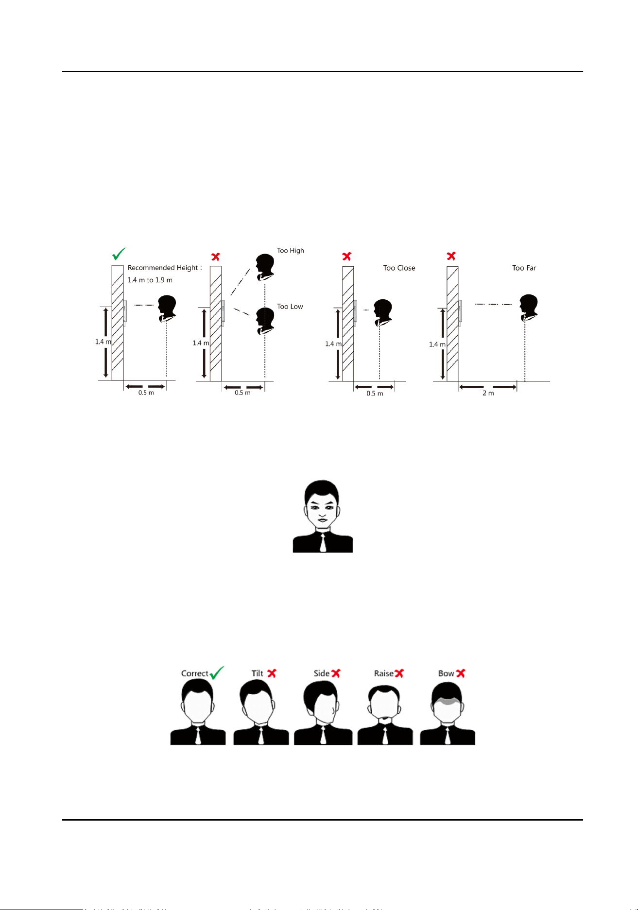
Appendix A. Tips When Collecng/Comparing Face
Picture
The posion when collecng or comparing face picture is as below:
Posions (Recommended Distance: 0.5 m)
Expression
●
Keep your expression naturally when collecng or comparing face pictures, just like the
expression in the picture below.
●
Do not wear hat, sunglasses, or other accessories that can aect the facial recognion funcon.
●
Do not make your hair cover your eyes, ears, etc. and heavy makeup is not allowed.
Posture
In order to get a good quality and accurate face picture, posion your face looking at the camera
when collecng or comparing face pictures.
DS-K1TA70 Series Face Recognion Terminal User Manual
206

Size
Make sure your face is in the middle of the collecng window.
DS-K1TA70 Series Face Recognion Terminal User Manual
207
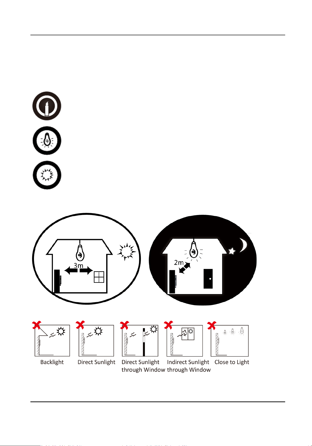
Appendix B. Tips for Installaon Environment
1. Light Source Illuminaon Reference Value
Candle: 10Lux
Bulb: 100~850Lux
Sunlight: More than 1200Lux
2. Install the device at least 2 meters away from the light, and at least 3 meters away from the
window or door.
3.Avoid backlight, direct and indirect sunlight
DS-K1TA70 Series Face Recognion Terminal User Manual
208
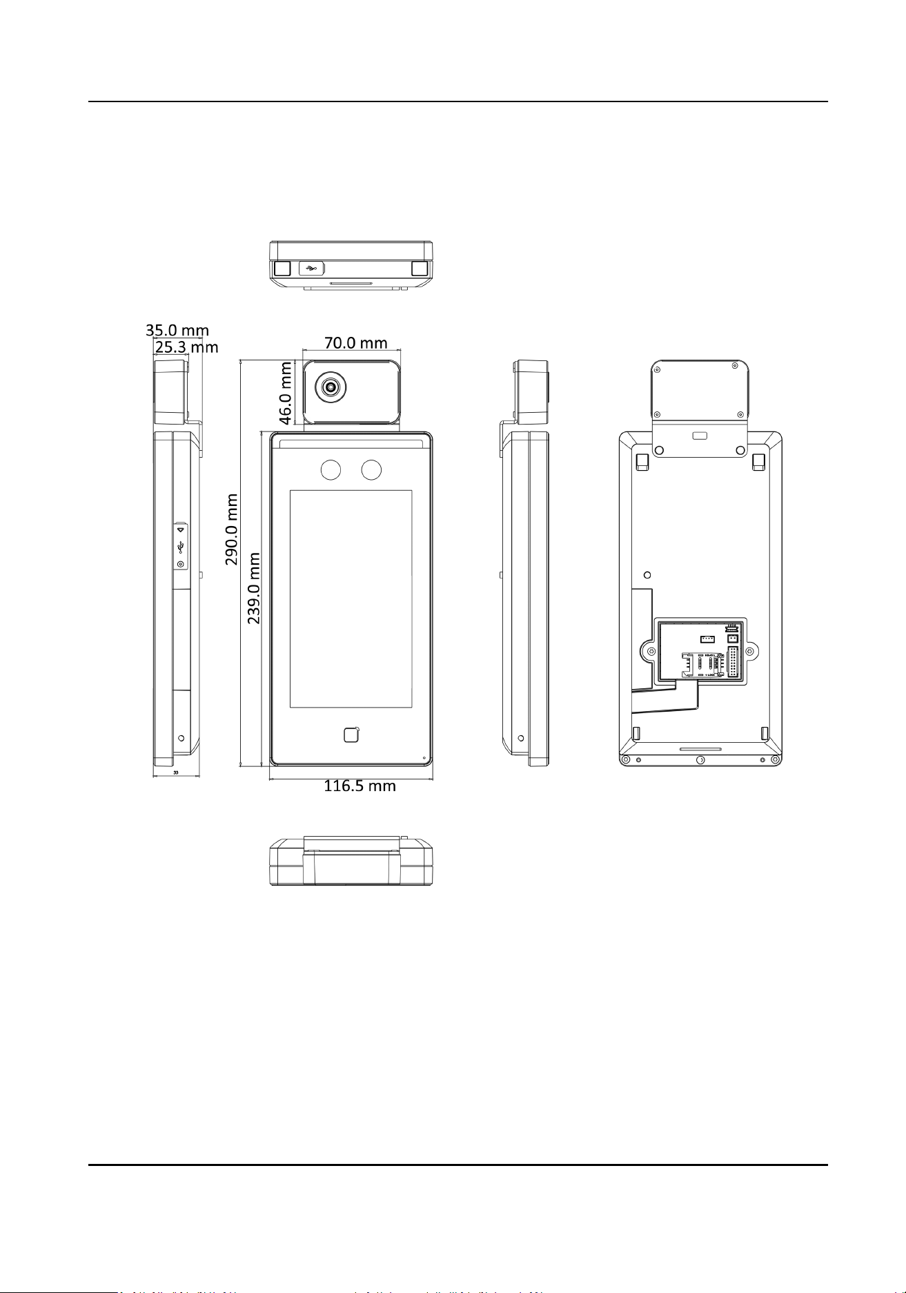
Appendix C. Dimension
DS-K1TA70 Series Face Recognion Terminal User Manual
209
Appendix D. Communicaon Matrix and Device
Command
Communicaon Matrix
Scan the following QR code to get the device communicaon matrix.
Note that the matrix contains all communicaon ports of Hikvision access control and video
intercom devices.
Figure D-1 QR Code of Communicaon Matrix
Device Command
Scan the following QR code to get the device common serial port commands.
Note that the command list contains all commonly used serial ports commands for all Hikvision
access control and video intercom devices.
Figure D-2 Device Command
DS-K1TA70 Series Face Recognion Terminal User Manual
210

UD22684B-E