TPI Corporation
P.O. BOX 4973
JOHNSON CITY, TN 37602
www.tpicorp.com
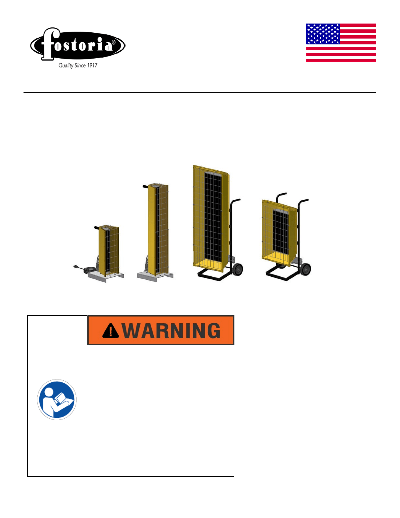
FSP-Series
Heavy-Duty Flat Panel Emitter
Electric Portable Infrared Heaters
REFER TO COMPLETE
INDEX OF
INFORMATION ON
PAGE 2
ISSUE DATE 7/2015 REV. DATE- REV. LEVEL: - ECO 1-7092 OIPM P/N 8420 PG 1 OF 11
FSP-14
FSP-31
FSP-95
FSP-43
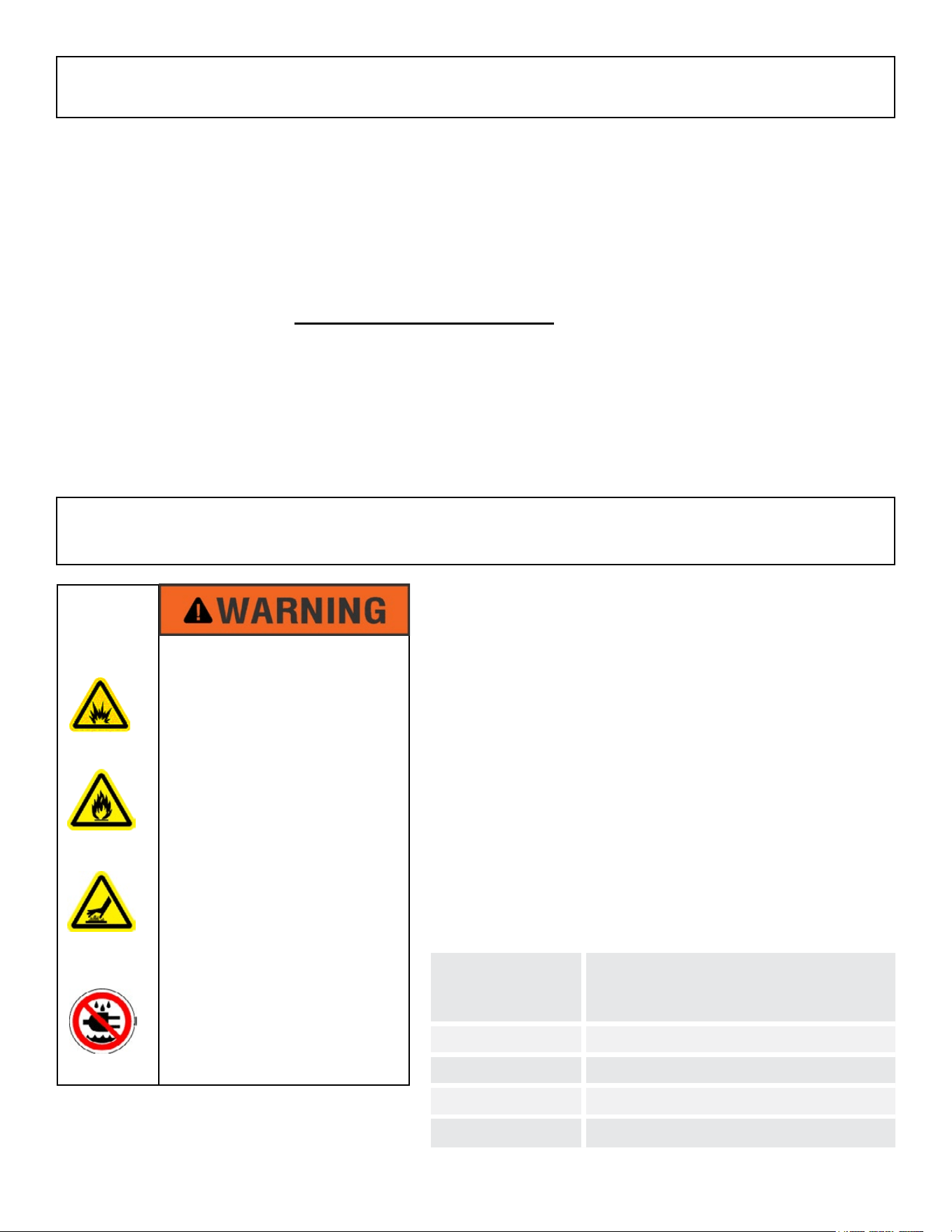
IMPORTANT SAFETY
INFORMATION INSIDE
• Serious injury or death possible
• Read, understand, and follow all
safety information and instruc-
tions in this manual before using
or servicing this product.
• Retain these instructions for fu-
ture reference.
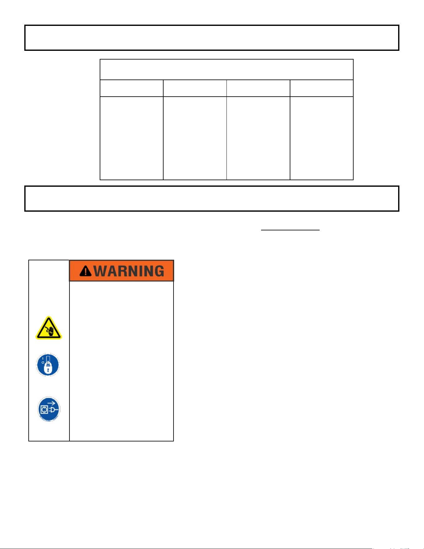
SIGNAL WORD DEFINITIONS
DANGER indicates an imminently hazardous situation
which, if not avoided, will result in death or serious injury.
WARNING indicates a potentially hazardous situation which,
if not avoided, could result in death or serious injury.
CAUTION indicates a potentially hazardous situation which,
if not avoided, may result in minor or moderate injury.
CAUTION used without the safety alert symbol indicates a
potentially hazardous situation which, if not avoided, may
result in property damage.
As dened in ANSI Z535.4-2002
ISSUE DATE 7/2015 REV. DATE- REV. LEVEL: - ECO 1-7092 OIPM P/N 8420 PG 2 OF 11
General Description & Use Page 3
Specications Page 4, 5
Installation Planning Page 5, 6, 7
Installation - Wiring Page 7, 8, 9
Operation Page 10
Maintenance Page 11
Accessories Page 11
INDEX
ATTENTION:
The table to the right provides
denitions of the signal words
that an be found throughout
this manual.
These signal words
are used to express the severity of
the hazard at hand.
The signal
words are generally used in
conjunction with safety symbols
that correspond to the text for
that particular
hazard
.
As you
read this manual, refer back
to this table when you are
unsure of the signal word
denition.
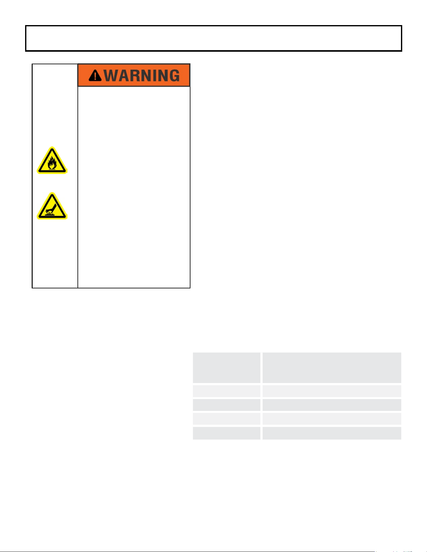
EXPLOSION HAZARD
FIRE HAZARD
BURN HAZARD
• Serious injury or death may
occur.
• Not for indoor residential use.
• Do not use outdoors in wet
conditions and in unprotected
locations.
• Use for comfort heating only.
• Do not use in locations con-
taining hazardous or explosive
atmospheres.
ISSUE DATE 7/2015 REV. DATE- REV. LEVEL: - ECO 1-7092 OIPM P/N 8420 PG 3 OF 11
Thank you very much for selecting Fostoria’s portable electric infrared heating equipment for your
com
fort heating needs.
These products were engineered with the most reliable components and
mate
rials available and are equipped with features to assure ease of installation and maintenance.
The warmth you will now enjoy when using this heating equipment is created by a heat source; a at
panel emitter; that emits infrared energy in the form of heat, like the sun. This is an economical way
to heat because it heats people and objects, not the air, so you don’t need to heat a large area to feel
warm.
CHECKING YOUR SHIPMENT
• Upon receipt of your shipment, check all cartons for visible damage.
• Claims for damaged material or shortages that were not evident upon receipt of shipment must be
reported to carrier and TPI Corporation’s customer service (800-251-0382) immediately.
• Any accessory items ordered for the heater will be shipped in separate cartons.
The Fostoria FSP-series is a line of heavy-duty por
table
heaters designed to provide electric infra
red heat when
permanently installed heaters are not practical or
eco
nomical. They are easily transported
to the work site
and connected to disconnect switch
es or lighting centers.
The units are suited to a wide variety of indoor and
pro
tected outdoor commercial or industrial uses. They
operate cleanly, emitting no fumes or odors.
Applications where combustible materials and/or
person
nel will be located near these heaters require the
addition of a ground-fault sensing switch as part of the
electrical circuit. See the INSTALLATION PLANNING
section of this manual for more details. Any installation
of
these heaters must also adhere to the minimum clearance
information below.
THANK YOU!!
GENERAL DESCRIPTION & USE
MODEL
REQUIRED CLEARANCES
TO COMBUSTIBLES FROM
FRONT OF HEATER
FSP-1412-1C 3 FEET
FSP-31 3 FEET
FSP-43 4 FEET
FSP-95 7 FEET
ISSUE DATE 7/2015 REV. DATE- REV. LEVEL: - ECO 1-7092 OIPM P/N 8420 PG 4 OF 11
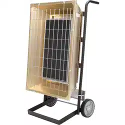
FSP-14 & FSP-31 Series:
• Aluminized steel base and large carry
handle.
• Gold-anodized aluminum housing for good
reectivity and corrosion resistance
• 120V model (FSP-1412-1C) is equipped
with 15ft cordset with NEMA 5-15 molded
plug.
• Heavy-duty wire guard for element and
personnel protection.
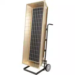
FSP-43 & FSP-95 Series:
• Heaters are mounted on steel handcarts with
6-inch wheels, which allow easy transport to the
job site.
• Gold-anodized aluminum housing for good
reectivity and corrosion resistance.
• Heavy-duty wire guard for element and personnel
protection.
Please see illustrations on next page regarding dimensions in table.
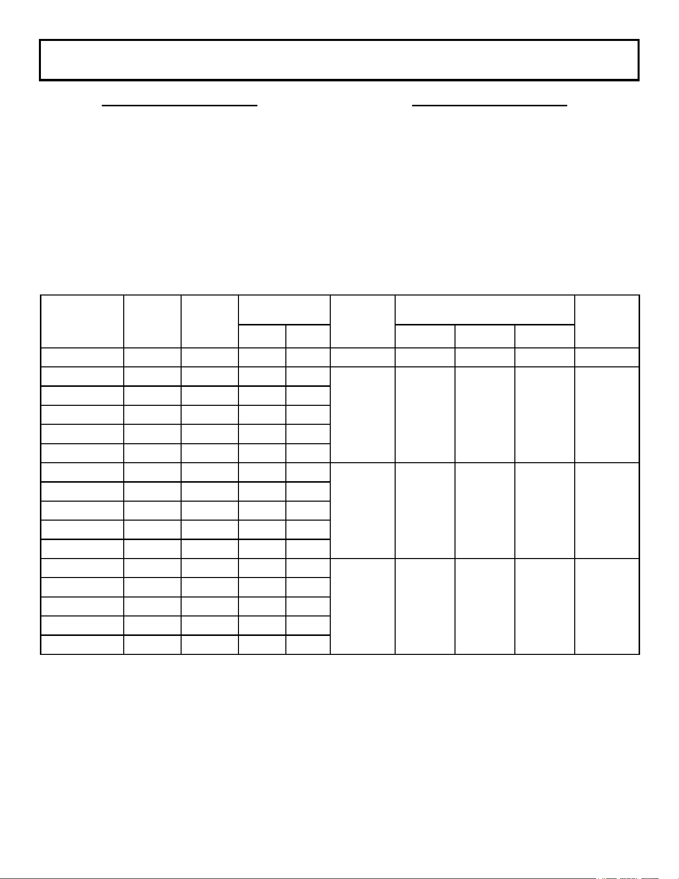
TABLE A
SPECIFICATIONS
MODEL VOLTS WATTS
AMPS
Btu’s/Hr
Dimensions (INCHES)
WEIGHT
(lbs)
1PH 3PH A B C
FSP-1412-1C 120 1450 12.1 N/A 4947 14-1/2 11-1/2 25 17
FSP-3120-1 208 3150 15.4 N/A
10,749 14-1/2 11-1/2 46-1/4 23
FSP-3124-1 240 3150 13.13 N/A
FSP-3127-1 277 3150 11.37 N/A
FSP-3148-1 480 3150 6.56 N/A
FSP-3157-1 600 3150 6.48 N/A
FSP-4320-3 208 4300 20.67 11.94
14,672 17-1/2 20 37-1/2 32
FSP-4324-3 240 4300 17.91 10.36
FSP-4327-1 277 4300 15.52 N/A
FSP-4348-1 480 4300 8.96 5.18
FSP-4357-1 600 4300 7.48 7.48
FSP-9520-3 208 9500 45.67 26.39
32,414 17-1/2 20 53 46
FSP-9524-3 240 9500 39.68 22.89
FSP-9527-1 277 9500 34.3 N/A
FSP-9548-3 480 9500 19.79 11.44
FSP-9557-3 600 9500 16.52 9.54
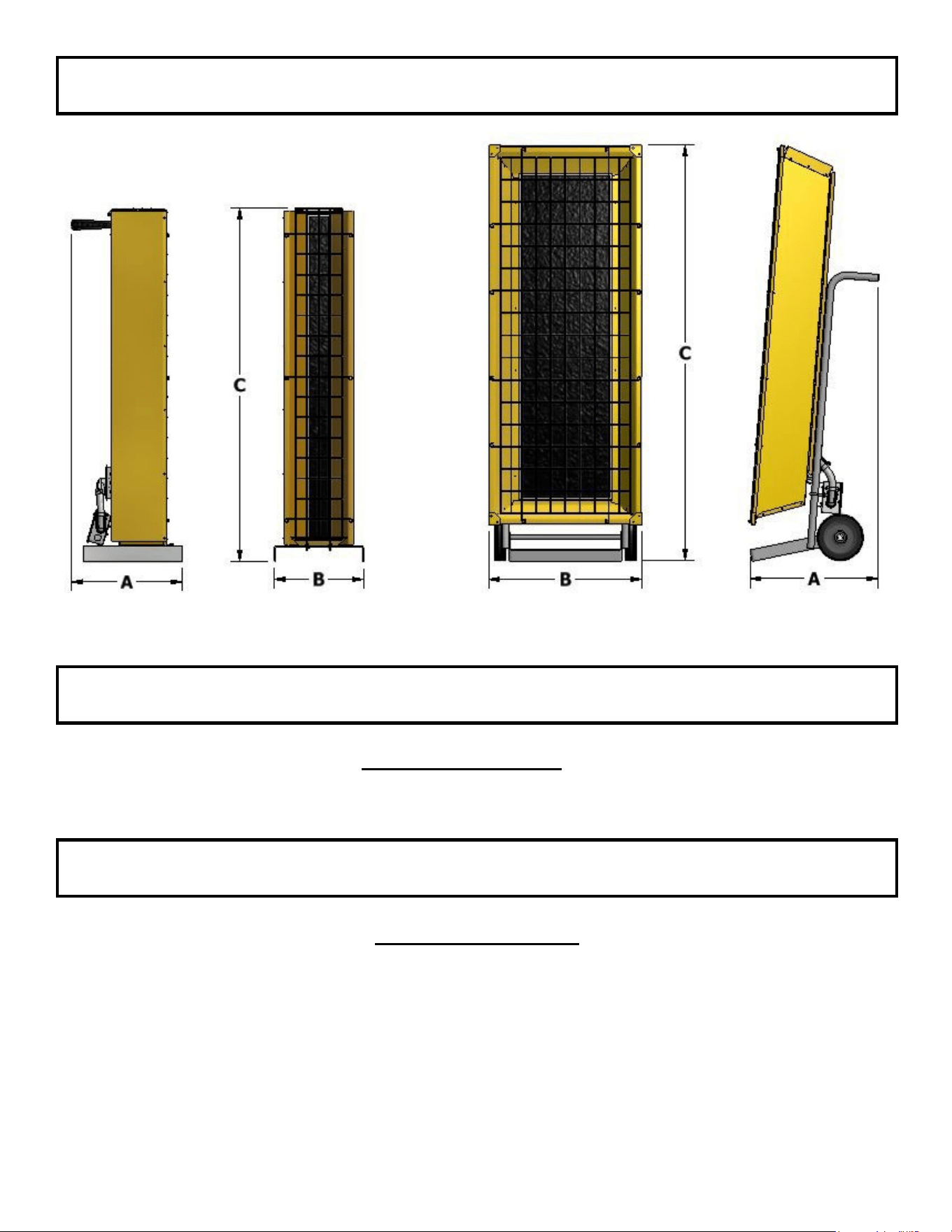
FSP-14, FSP-31 FSP-43, FSP-95
Installer Qualications
The installation and wiring of Fostoria FSP heaters must be performed by a licensed electrician.
SPECIFICATIONS (con’t.)
Installer Responsibility
The National Electric Code (NEC) and local codes and ordinances together with specications
provided by Fostoria comprise the information needed for proper installation. The installer must furnish
all materials that have not been purchased from Fostoria or its representatives. It is the installers
responsibility that the materials and methods of installation result in a job that is workmanlike and
compliant with all applicable codes.
ISSUE DATE 7/2015 REV. DATE- REV. LEVEL: - ECO 1-7092 OIPM P/N 8420 PG 5 OF 11
SPECIFICATIONS (con’t.)
INSTALLATION PLANNING
ISSUE DATE 7/2015 REV. DATE- REV. LEVEL: - ECO 1-7092 OIPM P/N 8420 PG 6 OF 11
Preparations for Wiring Heaters
• The maximum ampacity rating for an
infrared heating circuit is 48.
• The opening in the terminal
box for
branch circuit supply wiring on FSP-14
and FSP-31 models is sized for 1/2-inch
trade size cable connectors.
Openings
in terminal boxes for supply wiring on
FSP- 43 and FSP-95 models are sized
for 3/4-inch trade size cable connectors.
• Cable connectors and cables are not
provided with these heaters.
(See
Specications on page 7 for
exceptions.)
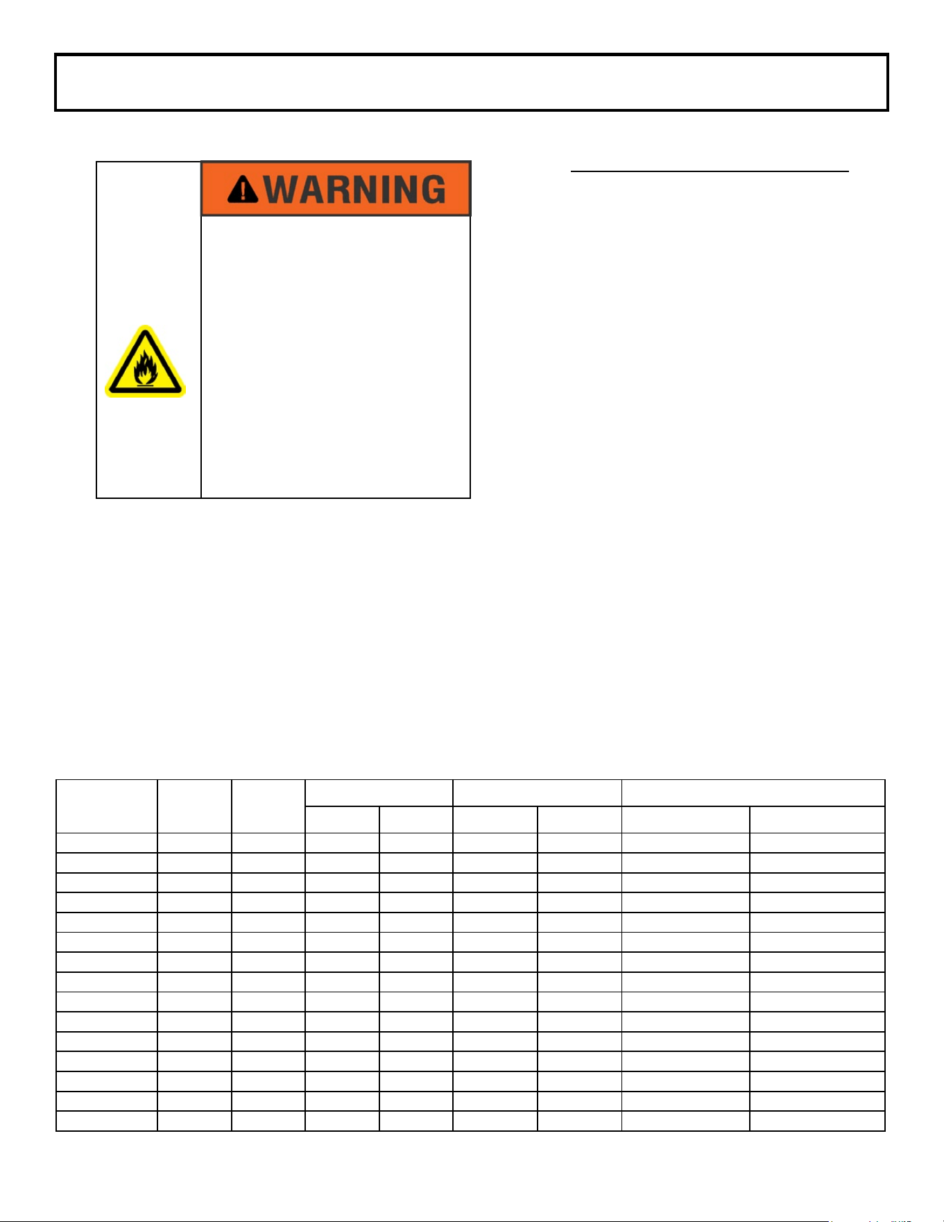
The following tables are provided to assist the licensed electrician in sizing the electric cables and/or
plugs needed for each FSP heater model. Since only model FSP-1412-1C is equipped with cables and
plugs, these items for all other models will have to be obtained through a local supplier or purchased
separately from Fostoria. (See Table B.)
All supply cables must be copper, rated 90°C and comply with all local codes and the National Electric
Code (NEC).
All recommended wire sizes assume a 50ft. maximum wire length.
INSTALLATION PLANNING (con’t.)
FIRE HAZARD
• Serious injury or death may
occur.
• Heater circuit load calculations
and circuit design must be
done by a licensed electrician
or engineer.
MODEL VOLTS WATTS
AMPS TYPE SO CABLE SIZE PLUG SIZE
1-PH 3-PH 1-PH 3-PH 1-PH 3-PH
FSP-3120-1 208 3150 15.14 N/A 14/3 N/A 20A/250V/3 WIRE N/A
FSP-3124-1 240 3150 13.13 N/A 14/3 N/A NEMA L6-16 N/A
FSP-3127-1 277 3150 11.37 N/A 16/3 N/A NEMA L7-17 N/A
FSP-3148-1 480 3150 6.56 N/A 16/3 N/A NEMA L8-20 N/A
FSP-3157-1 600 3150 5.48 N/A 16/3 N/A NEMA L9-20 N/A
FSP-4320-3 208 4300 20.67 11.94 12/3 14/4 30A/250V/3 WIRE 20A/250V/4 WIRE
FSP-4324-3 240 4300 17.91 10.36 14/3 14/4 30A/250V/3 WIRE 20A/250V/4 WIRE
FSP-4327-1 277 4300 15.52 N/A 14/3 N/A 20A/480V/3 WIRE N/A
FSP-4348-3 480 4300 8.96 5.18 16/3 14/4 20A/480V/3 WIRE 20A/480V/4 WIRE
FSP-4357-3 600 4300 7.48 7.48 16/3 14/4 20A/600V/3 WIRE 20A/600V/4 WIRE
FSP-9520-3 208 9500 45.67 26.39 6/3 8/4 60A/250V/3 WIRE 20A/600V/4 WIRE
FSP-9524-3 240 9500 39.58 22.89 8/3 10/4 50A/250V/3 WIRE 30A/250V/4 WIRE
FSP-9527-1 277 9500 34.3 N/A 8/3 N/A 50A/480V/3 WIRE N/A
FSP-9548-3 480 9500 19.79 11.44 12/3 14/4 30A/480V/3 WIRE 20A/480V/4 WIRE
FSP-9557-3 600 9500 16.52 9.54 14/3 14/4 20A/600V/3 WIRE 20A/600V/4 WIRE
ISSUE DATE 7/2015 REV. DATE- REV. LEVEL: - ECO 1-7092 OIPM P/N 8420 PG 7 OF 11
For All Heaters
The FSP-series heaters do not have any on board controls
and therefore all permanently connected heaters must be
used in conjunction with the applicable Fostoria FPC-series
control center or be wired to a listed, properly rated safety
switch for on/off control. Always disconnect the power at the
circuit breaker or disconnect switch before installing electric
power to the heater. If the breaker or disconnect switch
cannot be seen from where you will be working, lock it in the
open position and tag it to prevent unexpected application
of power. Failure to do so could result in fatal electric shock.
Do not depend on a thermostat or other switch as the sole
means of turning off power to the heater.
To disconnect power to heaters using wall receptacles and
plugs, simply unplug the heater.
“Bonding” is the intentional electrical connection of all non-current
carrying metal parts to the equipment grounding (green) conductor
of the heater and then terminating this green conductor to the green
conductor of the power supply to form a low-impedance path back
to the power supply so that safety devices (circuit breakers, fuses)
can quickly remove dangerous touch voltage from these parts when
a fault occurs.
Always securely connect the green conduc-
tor from the power supply to the green conductor of the
heater
.
INSTALLATION PLANNING (con’t.)
Table B
ELECTRIC CABLES
SIZE/TYPE PART NUMBER SIZE/TYPE PART NO.
16/3 SO
14/3 SO
14/4 SO
12/3 SO
12/4 SO
10/3 SO
08804300
08804600
08804900
08804500
03164201
08804400
8/3 SO
8/4 SO
6/4 SO
4/3 SO
2/3 SO
08805200
08805100
03164001
08805300
08804700
INSTALLATION-WIRING
ELECTRIC SHOCK
HAZARD
• Serious injury or death
may occur.
• Disconnect heater and
lock out from electrical
supply before installing or
servicing.
• Alway securely connect
green wire on heater to
bonding (green) wire from
electrical supply.

Wiring of FSP- Series Heaters
Since all FSP- Series heaters (except FSP-1412-1C) are received without an electric cable, the following
steps must be taken before attaching the heater to the base:
1. Install a standard or liquid-tight cable connector into the hole in the side of the terminal box. (See
page 6 for appropriate cable connector sizes.) Note: If a connector larger than 3/4” is required, a
hole must be pulled in the the junction box cover to accommodate the required tting size.
An
extension ring may be used to provide additional wiring space.
2. Place the properly sized supply cable through the tting. See page 6 for cable and plug size
specications or refer to the National Electric Code (NEC).
3. Connect supply cable leads to the element lead wires in the terminal box with wire nuts or other
safe mechanical means. Black and white cable leads can be connected to either element lead wire.
Connect green lead from supply cable to green (bonding) lead in the terminal box. See page 9 for
wiring options.
4. Secure handle to rear of FSP-14 and FSP-31.( Not required on other models.)
5. Connect heater to appropriate electric circuit.
ISSUE DATE 7/2015 REV. DATE- REV. LEVEL: - ECO 1-7092 OIPM P/N 8420 PG 8 OF 11
INSTALLATION - WIRING
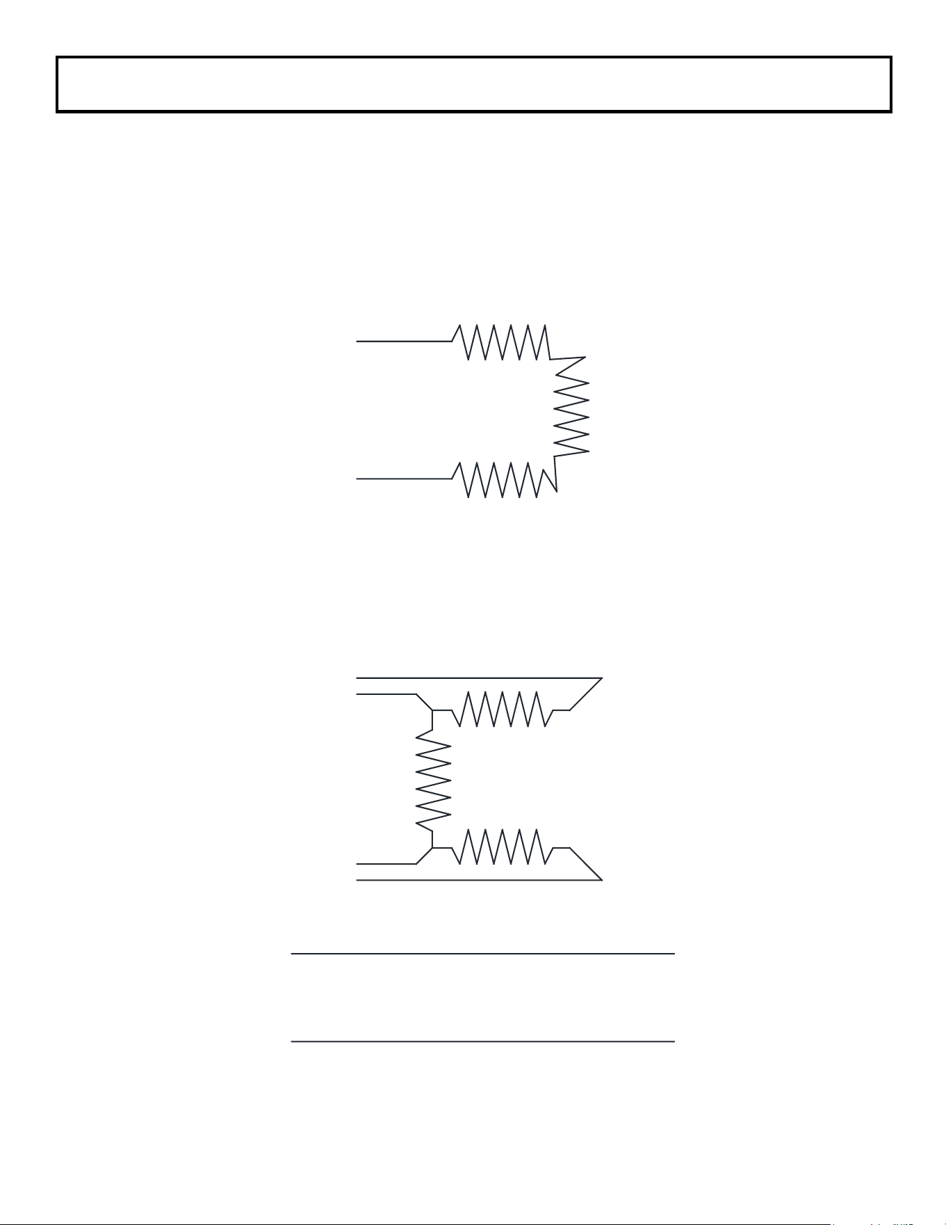
1
2
3
4
FOR 3PH OPERATION
L1-1 & 4,L2-2,L3-3.
FOR 1PH OPERATION
L1-1 & 3, L2(N)-2 & 4.
WIRING SCHEMATIC
L1
L2(N)
FOR FSP-14, FSP-31 FSP-4327-1
AND FSP-9527-1 MODELS
FOR ALL OTHER MODELS
ISSUE DATE 7/2015 REV. DATE- REV. LEVEL: - ECO 1-7092 OIPM P/N 8420 PG 9 OF 11
INSTALLATION-WIRING (con’t)
ISSUE DATE 7/2015 REV. DATE- REV. LEVEL: - ECO 1-7092 OIPM P/N 8420 PG 10 OF 11
When power is provided to these heaters the heater
elements will take several minutes to achieve full
infrared output that can be conrmed by an orange
to dull red glow on the element face
.
The element
coil under this condition is operating between
1,500 and 1,600° F emitting medium wave
length (approx. 3 microns or millionths of a
meter) infrared energy.
T
his energy, that
can also be considered “radiation” is not
harmful, yet is very effective at heating
objects and surfaces that are within the
line-of-sight of the elements and the
heater’s reective surfaces.
When power is provided or removed from these
heaters, you may hear unfamiliar sounds that are
caused by the expansion and contraction of metal
components in the heater. This is normal.
There are no on/off switches, tip-over switches or
over-temperature safety cut out devices included
on any of these heaters.
See the Accessories
section of this manual for more details.
EXPLOSION HAZARD
FIRE HAZARD
BURN HAZARD
• Serious injury or death may
occur.
• Always operate heaters on
level surfaces.
• Allow heater to fully cool after
power is removed before
touching or working on it.
• Do not leave heaters unat-
tended while in operation.
• Maintain minimum clearances
to combustibles as shown in
table below.
OPERATION
MODEL
REQUIRED CLEARANCES
TO COMBUSTIBLES FROM
FRONT OF HEATER
FSP-1412-1C 3 FEET
FSP-31 3 FEET
FSP-43 4 FEET
FSP-95 7 FEET
ISSUE DATE 7/2015 REV. DATE- REV. LEVEL: - ECO 1-7092 OIPM P/N 8420 PG 11 OF 11
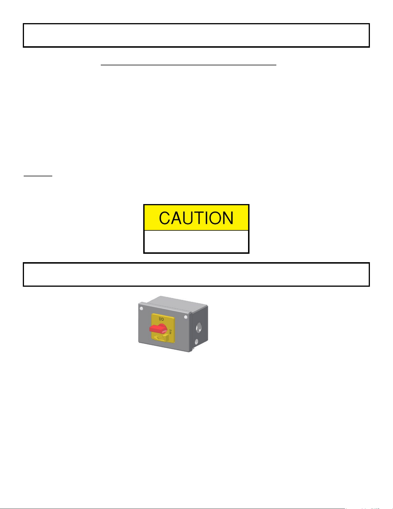
DC-SK-1
Disconnect switch
Part No.: 05893702
-Wall mountable for all FSP models
-Mounts directly on FSP-43 & FSP-95
models only
MAINTENANCE
ACCESSORIES
Pre-Season Maintenance and Annual Inspection
To ensure your safety and years of trouble-free operation from the heaters, periodic service and
inspections must be done by a trained maintenance person or licensed electrician.
To obtain maximum performance from your heater(s) each year, we recommend the following be
performed at the start of the heating season:
1. Clean housing reector surfaces with a damp cloth.
2. Blow or dust off the elements and inner reectors.
3. Repair or replace damaged power cables.
4. DO NOT hose-down these heaters.
Storage
When storing the heaters for long periods they should be covered to avoid accumulation of dust and
other contaminants. Keep them in dry areas away from dripping or standing water and heavy humidity.
• Do not store in a damp
location