2.25 TONNE LOW ENTRY TROLLEY JACK WITH
ROCKET LIFT
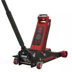
MODELS: 2001LEHV.V2, 2001LERE.V2, 2001LEBL.V2
Thank you for purchasing a Sealey product. Manufactured to a high standard, this product will, if used according to these instructions,
and properly maintained, give you years of trouble free performance.
IMPORTANT: PLEASE READ THESE INSTRUCTIONS CAREFULLY. NOTE THE SAFE OPERATIONAL REQUIREMENTS, WARNINGS & CAUTIONS. USE
THE PRODUCT CORRECTLY AND WITH CARE FOR THE PURPOSE FOR WHICH IT IS INTENDED. FAILURE TO DO SO MAY CAUSE DAMAGE AND/OR
PERSONAL INJURY AND WILL INVALIDATE THE WARRANTY. KEEP THESE INSTRUCTIONS SAFE FOR FUTURE USE.
1. SAFETY
WARNING! Please note that the handle socket of this jack is retained under tension and must be released
before use. Caution should be taken when releasing, as the handle socket will suddenly raise to its upright
position if not controlled.
9 The user shall work only in accordance with this instruction manual.
9 The operator shall be provided with all necessary information about training and about pumping and
translating forces.
9 Ensure the jack is in sound condition and good working order. Take action for immediate repair or
replacement of damaged parts. Use genuine parts only. DO NOT modify the jack. The use of non-genuine
parts may be dangerous and will invalidate the warranty.
9 Locate the jack in a suitable, well lit working area.
9 Keep working area clean and tidy and free from unrelated materials. Use jack on level and solid ground,
preferably concrete. Avoid tarmacadam as jack may sink in.
9 Chock wheels of vehicle.
9 Ensure the vehicle handbrake is engaged, engine is switched o and transmission is in gear (or “PARK”
if automatic).
9 Ensure minimum distance of 0.5m between vehicle and static objects such as doors, walls, etc. to allow
for vehicle tilting.
9 Ensure all non-essential persons keep a safe distance whilst the jack is in use.
9 Ensure there are no passengers in the vehicle.
9 It is necessary that the operator can watch the lifting device and the load during all movements.
9 Place jack under only those lifting points recommended by vehicle manufacturer (see vehicle handbook).
9 Check that the lifting point is stable and centred on the jack saddle.
9 Ensure the jack wheels are free to move and that there are no obstructions.
▲ DANGER: Use the jack for lifting only, NOT for supporting the lifted load.
9 Ensure there are no persons or obstructions beneath the vehicle before lowering.
9 It is not allowed to work under the raised load until it is secured by suitable means. Use suitable axle
stands under the vehicle before proceeding with any task.
9 Use a qualied person to lubricate and maintain the jack.
9 Ensure that only hydraulic jack oil is used in the jack.
8 DO NOT operate the jack if damaged.
8 DO NOT allow untrained persons to operate the jack.
8 DO NOT operate the jack when tired or under the inuence of drugs, alcohol or intoxicating medication.
8 DO NOT exceed the rated capacity of the jack.
8 DO NOT allow the vehicle to move during lifting or lowering, or use the jack to move the vehicle.
8 DO NOT jack vehicle if there is a risk of spillage of fuel, battery acid, or other dangerous substances.
8 DO NOT work under the vehicle until appropriately rated axle stands have been correctly positioned.
8 DO NOT use the jack for purposes other than that for which it is intended.
8 DO NOT top up hydraulic system with brake uid. Use hydraulic jack oil only. (Sealey Part No:
HJO500MLS or HJO5LS)
8 DO NOT adjust the safety overload valve.
9 When not in use store jack, fully lowered, in a safe, dry, childproof area.
9 If more than 400N of eort is generated in lifting, the eorts shall be lowered by an additional person.
9 Jacks shall be maintained and repaired in accordance with the manufacturer’s instructions. Such
maintenance and repair shall be carried out by qualied persons.
9 No modications shall be carried out which adversely aect the compliance of the jack with the standard.
9 Check the state of the markings and that the markings remain as the initial one.
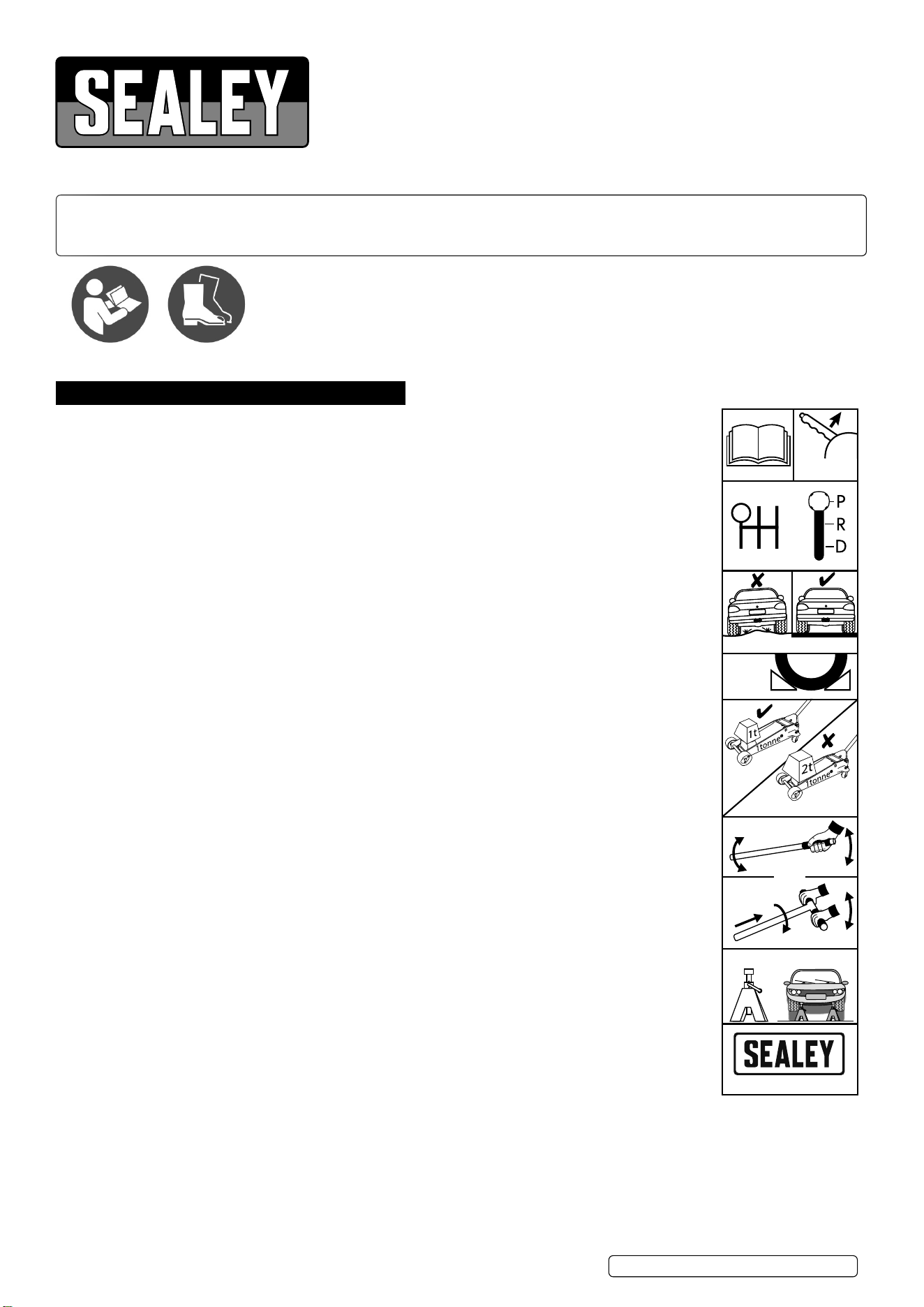
Refer to
instructions
Wear safety
footwear
1 3 5
2 4 R
TJL3
Chock
wheels
Never
exceed
jack capacity
Close
Raise
Lower
Lift & twist
to lower
OR
Use on a hard level floor
Apply
handbrake
www.sealey.co.uk
Use suitable axle stands
X2
Raise
Original Language Version
© Jack Sealey Limited
2001LE.V2 Issue 2 (H,1,4,F) 13/09/23
2. INTRODUCTION
Twin piston Rocket Lift feature brings saddle to maximum height in minimal strokes. Universal joint release mechanism allows safer,
more controlled lowering of jack. Proled lifting arm gives low clearance height of just 73mm making it suitable for sports and custom
cars. Heavy-duty steel chassis provides stability and endurance. Fitted with an overload valve for added safety. Hydraulic oil bypass
system protects ram from being overextended.
3. SPECIFICATION
Model ................................................2001LE.V2 Series
Capacity: .........................................................2.25tonne
Length: ................................................................734mm
Maximum Chassis Height: ..................................151mm
Maximum Saddle Height: ....................................495mm
Minimum Saddle Height: .......................................73mm
Replacement Rubber Jack Pad ...............................JP17
4. ASSEMBLY
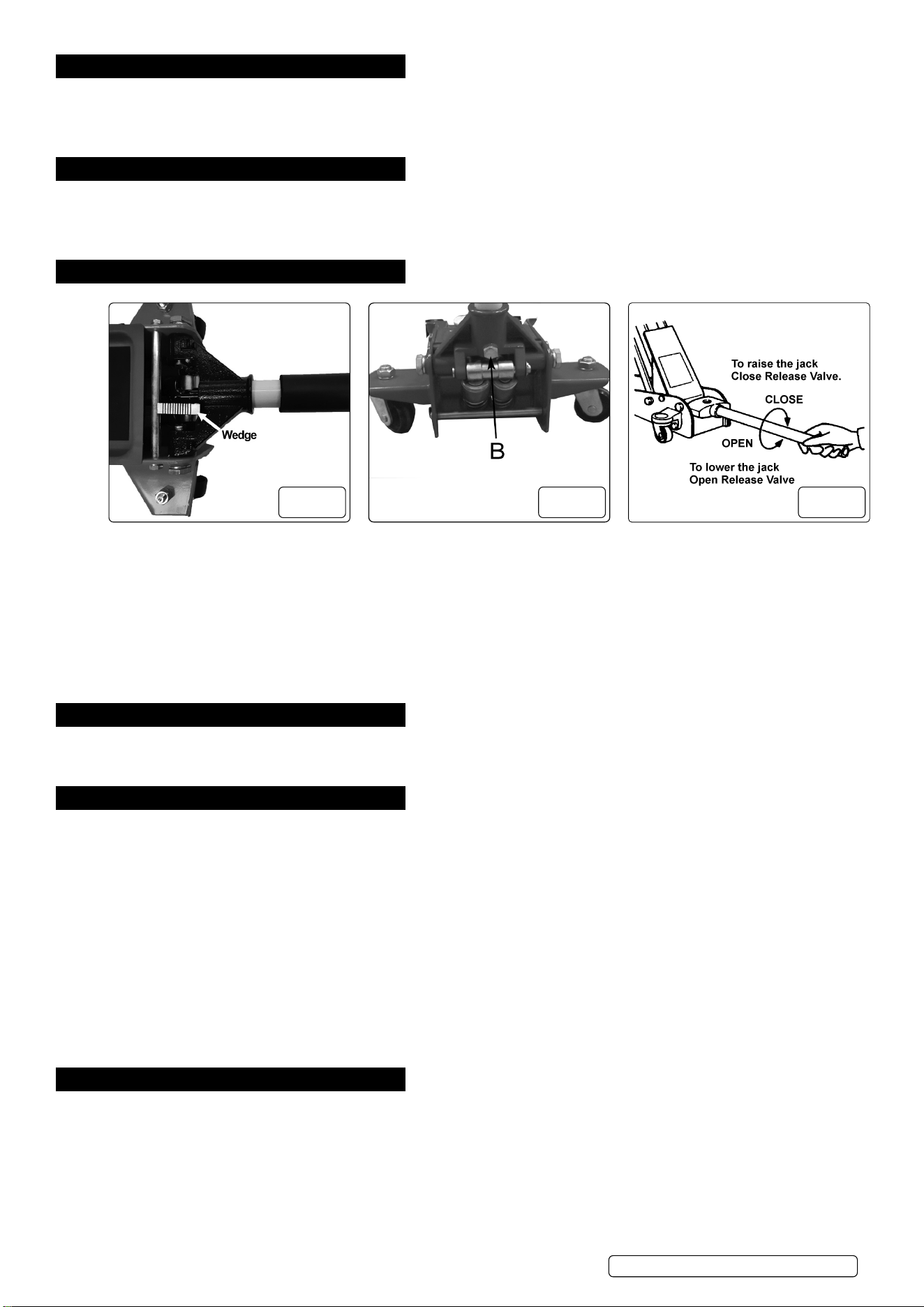
g.1 g.2 g.3
The jack comprises the following parts: Steel chassis and two part pumping handle.
4.1. RELEASING THE RETAINING WEDGE (FIG.1)
4.1.1. Seek assistance from a second person if required.
4.1.2. Insert the lower handle section into the handle socket and secure with the retaining bolt to aid in releasing pressure in the handle
socket.
4.1.3. Push down on the handle and hold down while removing the retaining wedge that is securing the handle socket in the down position.
4.1.4. Remove the wedge.
4.1.5. Gently and in a controlled manner slowly allow the lower handle section and handle socket to raise to their upright position.
4.2. Ensure the handle is engaged with the drive of the release valve before tightening the handle socket and screw (fig.2B).
4.2.1. Insert the upper half of the handle into the lower half. It is retained in place by a spring pin, see Parts Diagram.
5. HYDRAULIC SYSTEM PURGE
5.1. Open the release valve by turning it two full turns counter-clockwise.
5.2. Pump the handle a minimum of ten full strokes.
5.3. Close the release valve by turning it clockwise.
6. OPERATION
WARNING! Before use ensure you have read, understood and apply Section 1 Safety Instructions. IMPORTANT: Before use, the operator
is to visually inspect the jack for cracked welds, damaged or missing parts and hydraulic leaks.
6.1. RAISING A VEHICLE
6.1.1. Ensure that the jack and the vehicle are on a hard, level surface.
6.1.2. Always ensure that the vehicle handbrake is engaged and that the vehicle wheels are chocked.
6.1.3. Consult the vehicle manual to determine the location of jacking points. Position the jack under a suitable lifting point.
6.1.4. Turn the release valve clockwise, to the closed position (Fig.3). DO NOT over-tighten.
6.1.5. Raise the vehicle to the desired height by pumping the handle up and down.
6.1.6. Place axle stands beneath the locations recommended by the vehicle manufacturer.
6.1.7. Turn the release valve slowly counter-clockwise to lower the vehicle on to the axle
stands.
6.2. LOWERING A VEHICLE
6.2.1. Turn the release valve clockwise to the closed position.
6.2.2. Pump the handle to raise the vehicle off the axle stands.
6.3. Remove the axle stands from beneath the vehicle.
6.3.1. Turn the release valve slowly counter-clockwise to lower the vehicle to the ground.
NOTE: When not in use, ALWAYS leave the saddle and ram fully retracted.
7. MAINTENANCE
IMPORTANT: Only fully qualied personnel should attempt maintenance or repair.
Jacks shall be maintained and repaired in accordance with the manufacturer’s instructions. Such maintenance and repair shall be
carried out by qualied persons. No modications shall be carried out which adversely aect the compliance of the jack with the
standard. Check the state of the markings and that the markings remain as the initial one.
7.1. MONTHLY MAINTENANCE
7.1.1. Lubrication is critical to jacks, since they support heavy loads. Any restriction due to dirt or rust can cause either slow jack movement, or
extremely rapid jerks, causing damage to the internal components. To keep the jack well lubricated, carry out the following steps.
7.1.2. Lubricate the ram, the linkages and the saddle and pump mechanism with light oil.
7.1.3. Grease the wheel bearings and axles.
Original Language Version
© Jack Sealey Limited
2001LE.V2 Issue 2 (H,1,4,F) 13/09/23
7.1.4. Keep all jack surfaces and warning labels clean.
7.1.5. Check and maintain the ram oil level (Section 7.3).
7.2. THREE MONTHLY MAINTENANCE
7.2.1. At three monthly intervals, check the ram for any signs of rust or corrosion. Clean the ram as required and wipe with an oil cloth.
7.3. CHECKING THE OIL LEVEL
7.3.1. Fully retract the ram by turning the release valve counter-clockwise.
7.3.2. Undo the four top plate retaining screws and pull off plate.
7.3.3. With the jack in the level position, remove the rubber oil filler plug. DO NOT touch the other two screws.
7.3.4. The oil should be level with the bottom of the oil filler hole. If it is not, top up with clean hydraulic jack oil (Sealey Part No: HJO500MLS or
HJO5LS).
7.3.5. Replace the oil filler plug and check the jack operation.
7.3.6. Purge any air from the hydraulic unit as required. Refer to Section 5.
7.3.7. Replace the top plate and secure with the four screws.
NOTE: Always store the jack in the fully lowered position. This will protect critical areas from excessive corrosion.
IMPORTANT: NO RESPONSIBILITY IS ACCEPTED FOR INCORRECT USE OF THE PRODUCT.
7.3.8. Owing to their size and weight, hydraulic products should ideally be repaired by local service agents. We have service / repair agents in
most parts of the UK. Before returning your product please call our technical helpline on 01284 757505 for advice and troubleshooting
guidance. If the jack is under guarantee please contact your stockist.
7.4. DE-COMMISSIONING THE JACK
7.4.1. Should the jack become completely unserviceable and require disposal, draw off the oil into an approved container and dispose of the jack
and the oil according to local regulations.
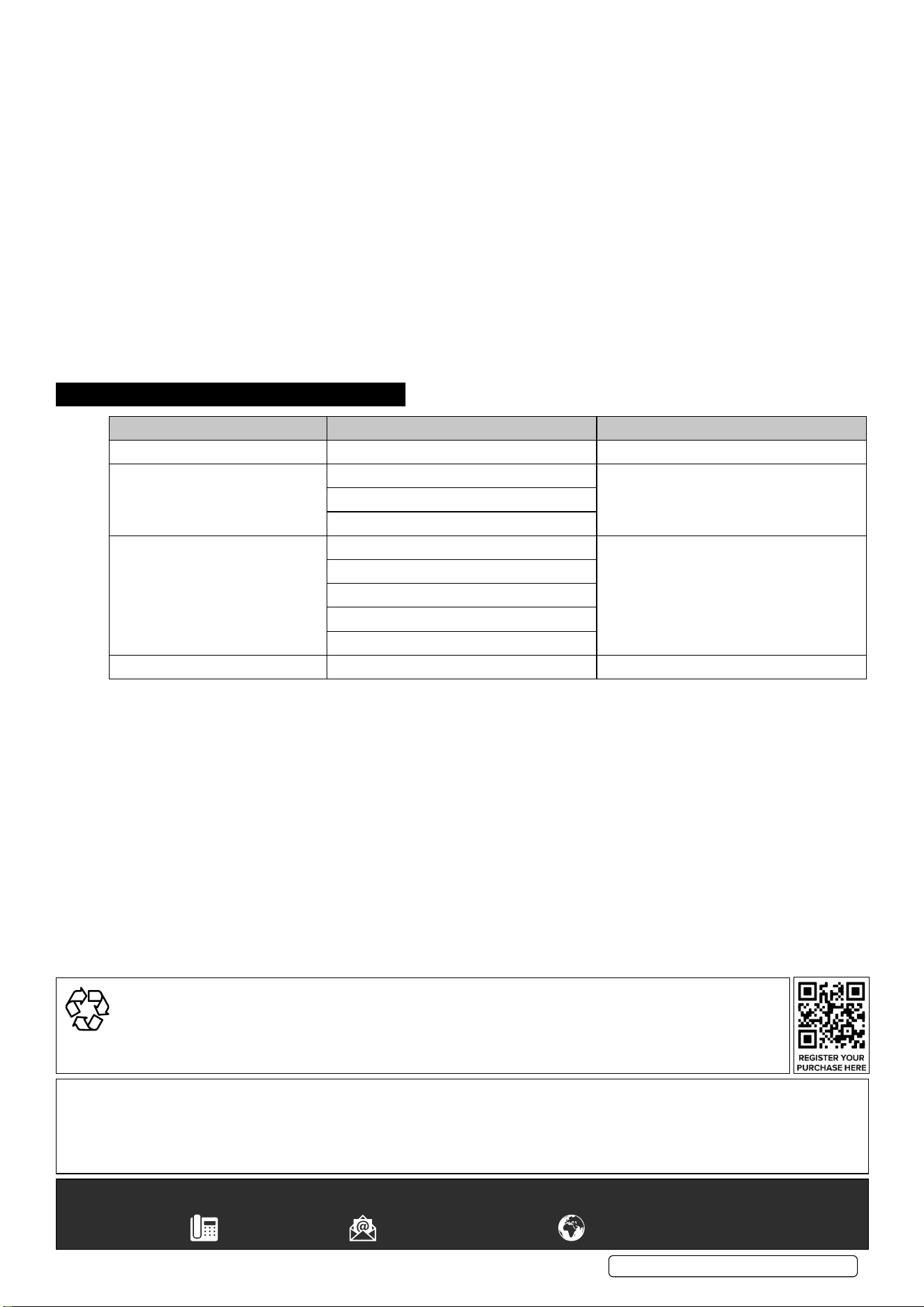
8. TROUBLESHOOTING
PROBLEM CAUSE REMEDY
Jack will not lift to full height Oil Level Low Check/Top up oil level
Jack will not hold the load Release valve not closing Contact authorised service agent
Hydraulic jack oil is contaminated
Pump valves not sealing
Lift arm will not lower Cylinder ram binding Contact authorised service agent
Parts worn
Internal component damage
Broken or unhooked return spring
Lift arm linkage either bent or binding
Jack feels spongy when lifting System requires purging Refer to air purge procedure in section 5
Sealey Group, Kempson Way, Suffolk Business Park, Bury St Edmunds, Suffolk. IP32 7AR
01284 757500 sales@sealey.co.uk www.sealey.co.uk
Note: It is our policy to continually improve products and as such we reserve the right to alter data, specifications and component parts without prior
notice. Please note that other versions of this product are available. If you require documentation for alternative versions, please email or call
our technical team on technical@sealey.co.uk or 01284 757505.
Important: No Liability is accepted for incorrect use of this product.
Warranty: Guarantee is 12 months from purchase date, proof of which is required for any claim.
Original Language Version
© Jack Sealey Limited
2001LE.V2 Issue 2 (H,1,4,F) 13/09/23
ENVIRONMENT PROTECTION
Recycle unwanted materials instead of disposing of them as waste. All tools, accessories and packaging should be sorted,
taken to a recycling centre and disposed of in a manner which is compatible with the environment. When the product
becomes completely unserviceable and requires disposal, drain any fluids (if applicable) into approved containers and
dispose of the product and fluids according to local regulations.