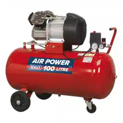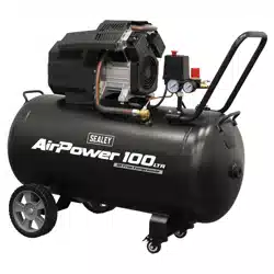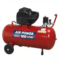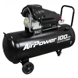
DIRECT DRIVE AIR COMPRESSORS
MODEL NO: SAC5030VA SAC10030VA
Thank you for purchasing a Sealey product. Manufactured to a high standard, this product will, if used according to these
instructions, and properly maintained, give you years of trouble free performance.
IMPORTANT: PLEASE READ THESE INSTRUCTIONS CAREFULLY. NOTE THE SAFE OPERATIONAL REQUIREMENTS, WARNINGS & CAUTIONS. USE
THE PRODUCT CORRECTLY AND WITH CARE FOR THE PURPOSE FOR WHICH IT IS INTENDED. FAILURE TO DO SO MAY CAUSE DAMAGE AND/OR
PERSONAL INJURY AND WILL INVALIDATE THE WARRANTY. KEEP THESE INSTRUCTIONS SAFE FOR FUTURE USE.
1. SAFETY
1.1. ELECTRICAL SAFETY
WARNING! It is the responsibility of the owner and the operator to read, understand and comply with the following: You must check
all electrical products before use to ensure that they are safe. You must inspect power cables, plugs, sockets and any other connectors
for wear or damage. You must ensure that the risk of electric shock is minimised by the installation of appropriate safety devices. A
Residual Current Circuit Breaker (RCCB) should be incorporated in the main distribution board. We also recommend that a Residual
Current Device (RCD) is used. It is particularly important to use an RCD with portable products that are plugged into a supply which is
not protected by an RCCB. If in any doubt consult a qualified electrician. You must also read and understand the following instructions
concerning electrical safety:
1.1.1. The Health & Safety at Work Act 1974 makes owners of electrical appliances responsible for the safe condition of those appliances
and the safety of the appliance operators. If in any doubt about electrical safety, contact a qualified electrician.
1.1.2. Ensure that the insulation on all cables and on the appliance is safe before connecting it to the power supply.
1.1.3. Ensure that cables are always protected against short circuit and overload.
1.1.4. Regularly inspect power supply cables and plugs for wear or damage and check all connections to ensure that none are loose.
1.1.5. Important: Ensure that the voltage marked on the appliance matches the power supply to be used and that the plug is fitted with the
correct fuse.
8 DO NOT pull or carry the appliance by the power cable.
8 DO NOT pull the plug from the socket by the cable.
8 DO NOT use worn or damaged cables, plugs or connectors. Immediately have any faulty item repaired or replaced by a qualified
electrician.
1.1.6. Over/current Protection: The user has to make provision for the installation of the over-current protection of the power circuit.
1.1.7. Electrical disconnecting device: The user has to make provisions for the installation of the electrical disconnecting device of the power circuit.
NOTE: If using a transformer to supply the compressor, it must be rated at a minimum of 2kVA to allow the compressor to run efficiently.
1.2. GENERAL SAFETY
9 Before you connect the equipment to the mains supply make sure that the data on the rating plate are identical to the mains data .
9 Familiarise yourself with the application and limitations of the compressor.
9 Ensure the compressor is in good order and condition before use. If in any doubt DO NOT use the unit and contact your Sealey
Stockist.
9 Operation must be with all guards, covers, lids and enclosures correctly in place.
9 Fully assemble the compressor before using for the first time.
9 The concentration of processed gases that can displace breathing air shall be kept within acceptable levels. Reference EN 12021 for
acceptable levels of contaminants in breathing air.
9 Remove from mains supply when performing maintenance or inspections.
WARNING! Item must be serviced by an authorised agent. DO NOT tamper with or attempt to adjust pressure switch or safety valve.
8 DO NOT carry out any welding operations on any pressurised part of the vessel.
9 Before moving, or maintaining the compressor ensure it is unplugged from the mains supply and that the air tank pressure has been
9 vented.
9 Maintain the compressor in good condition and replace any damaged or worn parts. Use genuine parts only. Unauthorised parts may
be dangerous and will invalidate your warranty.
9 Delivery hoses should be fitted with a safety cord.
9 It is essential to use separators, water traps and drains which process the liquids produced by the compressor system is put into
operation.
9 The compressor may only be used in suitable rooms (with good ventilation and an ambient temperature from +5°C to +40°C). Ensure there
is no dust, acids, vapours, explosive gases, or inflammable gases in the room. The air intake should be from a clean, outside air source.
9 Read the instructions relating to any accessory to be used with this compressor. Ensure the safe working pressure of any air appliance
used exceeds compressors output pressure.
9 Ensure the safe working pressure of any air appliance used exceeds compressors output pressure. If using a spray gun, check that the
area selected for spraying is provided with an air change system/ventilation.
9 Ensuretheairsupplyvalveisturnedobeforedisconnectingtheairsupplyhosetomoveatransportablecompressorusethehandle
only. Lift the compressor so that the front leg gives enough clearance for manoeuvring but maintain unit’s centre of gravity in front of
the wheels. DO NOT attempt to lift or move the compressor by any other means.
9 Usethecompressorinawellventilatedareaandensureitisplacedonarmsurface.
Refer to
instructions
Wear eye
protection
Wear ear
protection
Ensure oil level
is correct before
rstuse
WARNING:
High Voltage
WARNING:
Hot surface
WARNING:
Automatic
start up
Indoor use only DO NOT open
the air cock
before an air
hose is attached
Original Language Version
© Jack Sealey Limited SAC5030VA SAC10030VA Issue 4 (3) 24/05/24
9 Keep tools and other items away from the compressor when it is in use, and keep area clean and clear of unnecessary items.
9 Ensure the air hose is not tangled, twisted or pinched.
9 Keep children and unauthorised persons away from the working area.
9 Only move the compressor by the handle (if portable).
8 DO NOTdis-assemblecompressorforanyreason.Theunitmustbecheckedbyqualiedpersonnelonly.
8 DO NOT use the compressor outdoors, or in damp, or wet, locations.
8 DO NOToperatewithinthevicinityofammableliquids,gasesorsolids.
8 DO NOT touch compressor cylinder, cylinder head or pipe from head to tank as these may be hot.
8 DO NOT use this product to perform a task for which it has not been designed.
8 DO NOTdefacethecerticationplateattachedtothecompressortank.
8 DO NOTcoverthecompressororrestrictairowaroundtheunitwhilstoperating.
▲ DANGER! DO NOT direct the output jet of air towards people or animals.
8 DO NOToperatethecompressorwithoutanairlter.
8 DO NOT allow anyone to operate the compressor unless they have received full instructions.
WARNING! The air tank is a pressure vessel and the following safety measures apply:
8 DO NOT tamper with the safety valve, DO NOT modify or alter the tank in any way and DO NOT strap anything to the tank.
8 DO NOT subject the tank to impact, vibration or to heat and DO NOT allow contact with abrasives or corrosives.
9 Drain condensation from tank daily and inspect inside walls for corrosion every three months and have a detailed tank inspection
carriedoutannually.Thetankshellmustnotfallbelowthecertiedthicknessatanypoint.
WARNING! If an electrical fuse blows, ensure it is replaced with an identical fuse type and rating.
9 When not in use, store the compressor carefully in a safe, dry, childproof location.
9 Whenthecompressorisnotinuse,itshouldbeswitchedo,disconnectedfromthemainssupplyandtheairdrainedfromthetank.
9 Under the PRESSURE SYSTEMS SAFETY REGULATIONS 2000 it is the responsibility of the owner of the compressor to initiate a
systemofinspectionthatbothdenesthefrequencyoftheinspectionandappointsapersonwhohasspecicresponsibilityfor
carrying out the inspection.
2. INTRODUCTION
V-Twin pump aluminium cylinder head with cast iron cylinder gives added resistance to wear. Pump head directly coupled to heavy-
duty induction motor for reliable and quiet operation. Precision welded receiver tank manufactured to meet Pressure Vessel Directive.
Suitable for general-purpose workshop applications. Fitted with fully automatic pressure cut-out switch and twin gauges displaying tank
and working pressures. Fitted with 3-pin plug.
3. SPECIFICATION
4. PREPARATION
4.1. Remove compressor from packaging and inspect for any shortages or damage. If anything is
found to be missing or damaged contact your supplier.
4.2. Save the packing material for future transportation of the compressor. We recommend that
you store the packing in a safe location, at least for the period of the guarantee. Then, if
necessary, it will be easier to send the compressor to the service centre.
4.3. Confirm that the mains voltage corresponds with the voltage shown on the compressor data
plate.
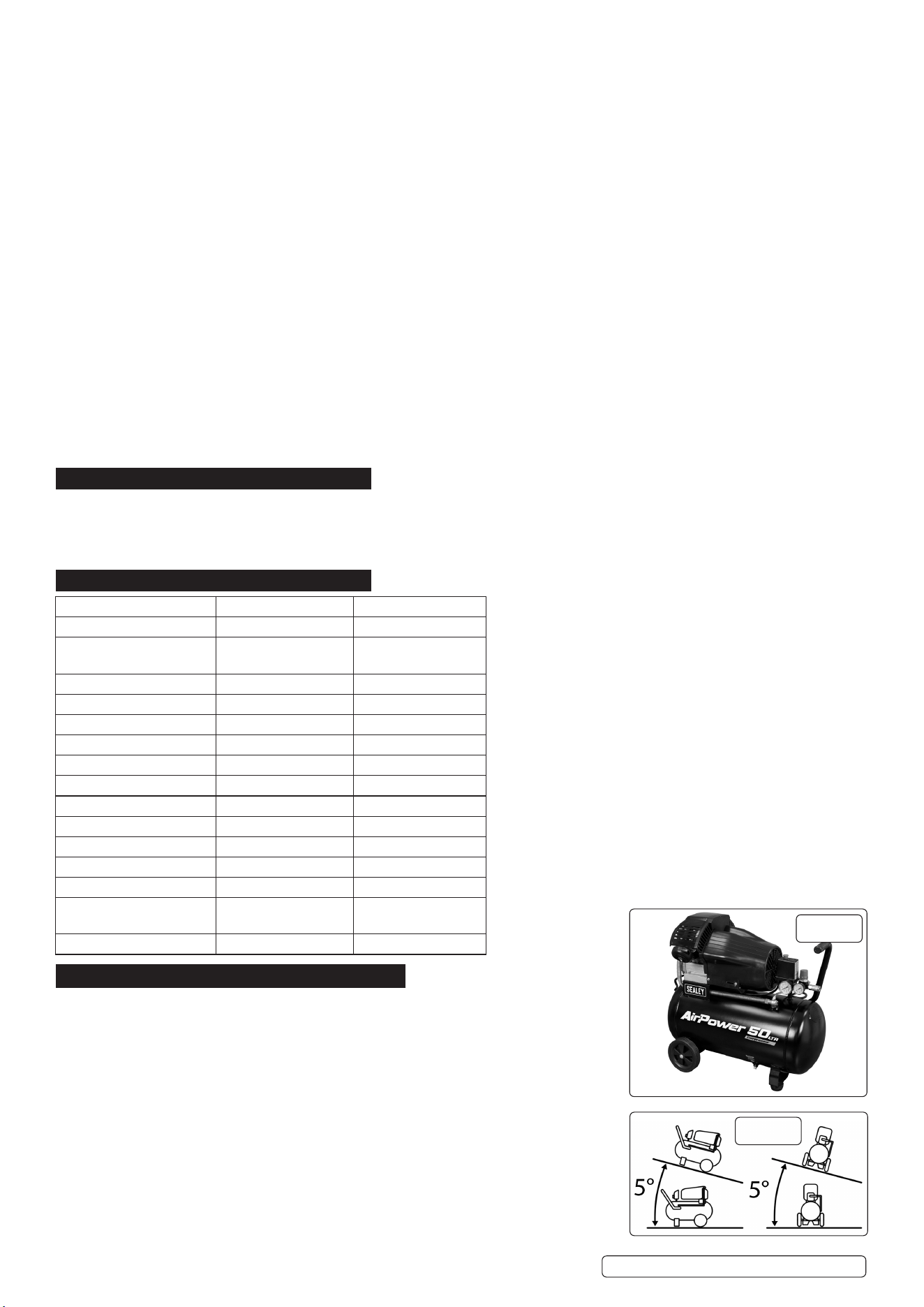
4.4. Assemble the wheels (fig.A.) to the main frame using the nuts, bolts and washers supplied.
4.5. Attach handle with bolts provided.
4.6. The compressor should be operated on a flat surface, or one that does not exceed 10°either
transversely or longitudinally (fig.1), and should be in a position that allows good air
circulation around the unit.
4.7. Before using the compressor check the oil level by referring to the oil sight glass
(fig.2C). If the oil level is not up to the red centre mark it should be further topped up with
recommended oil. Screw the filler/breather cap into the aperture as shown in fig.2B.
Model No: SAC5030VA SAC10030VA
Air Displacement cfm(L/min): 12.4cfm(350L/min) 12.4cfm(350L/min)
Maximum Free Air Delivery
cfm(L/min):
7cfm(198L/min) 7cfm(198L/min)
Maximum Pressure: 116psi(8bar) 116psi(8bar)
Minimum Rated Supply: 13A 13A
Motor Output: 3hp 3hp
Nett Weight: 38.8kg 48kg
Noise level: 97dB 97dB
Oil Capacity: 350ml 350ml
Outlet: Quick Release Coupling Quick Release Coupling
Phase: 1ph 1ph
Plug Type: 3-pin BS 3-pin BS
Power Cable length: 1.8m 1.8m
Reciver Capacity: 50L 100L
Size (W x D x H): 705mm x 335mm x
610mm
1040mm x 350mm x
720mm
Supply: 230V/13A 230V/13A
Additional Specication:
Short circuit current rating for each incoming power supply: 25A
Type of distribution system in the system: Lower voltage
Full load current for each incoming supply: 9A
Intended media: Air
Inlet intermediate pressure and temperatures: N/A
Inlet discharge pressure & temperatures: 0.8MPA
Temperature 70°C
Maximum pressure ratio: 0.8MPA
Pressure limits of the lubrication system: Pressure 0.1MPA / 1BAR
Temperature limits of the lubrication system: 100°C
Maximum speed of the unit: 2880RPM
Minimum speed of the unit: 2880RPM
g.1
g.A
Original Language Version
© Jack Sealey Limited SAC5030VA SAC10030VA Issue 4 (3) 24/05/24
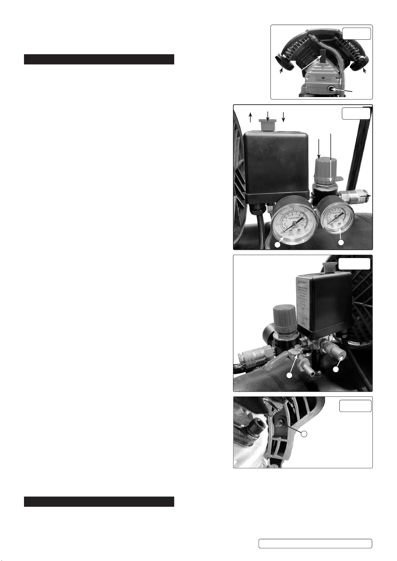
4.8. Screw the back half of a filter unit into the downward facing port openings
in each head as shown in fig.2A. Place a filter cover over each threaded
rod protruding from the back half of the filter and secure each with a wing
nut. Refer also to fig.5.
5. OPERATION
WARNING! ENSURE THAT YOU HAVE READ, UNDERSTOOD AND
APPLY SECTION 1 SAFETY INSTRUCTIONS.
5.1. IMPORTANT. The use of extension leads to connect this compressor
to the mains is not recommended as the resulting voltage drop reduces
motor, and therefore pump, performance and could damage your
compressor.
5.2. TAKE CARE WHEN SELECTING TOOLS FOR USE WITH THE
COMPRESSOR. Air tool manufacturers normally express the volume of
air required to operate a tool in cubic feet per minute (cfm). This refers to
free air delivered by the compressor (‘air out’) which varies according to the
pressure setting. DO NOT confuse this with the compressor displacement
which is the air taken in by the compressor (‘air in’). ‘Air out’ is always less
than ‘air in’ - due to losses within the compressor.
5.3. STARTING THE COMPRESSOR.
5.3.1. Yourcompressoristtedwithapush/pulltypeofON/OFFswitch.To
turn the compressor ‘ON’ pull the switch knob upwards. To turn the
compressor‘OFF’pushtheknobdownwards.(Seeg.3.1).
5.3.2. Check that the ON/OFF switch is in the “OFF” position, the regulator tap
(fig.3.2) is closed (Zero ‘0’ bar).
5.3.3. Plug mains lead into mains supply and start the compressor by pulling the
switch knob upwards.
5.3.4. When starting the compressor for the first time, leave it running for several
minutes with the air tap(g.3b.8) open to ensure good distribution of the
lubricating oil. Turn the compressor off and close the air tap. Restart the
compressor and leave it running with air tap (fig.3b.8) closed and regulator
(fig.3.2) set to maximum pressure. Make sure that pressure in the tank
rises and that the compressor stops automatically when the max. pressure
value allowed - written on the specification plate and shown on the gauge
(fig.3.6) - is achieved. The compressor will now operate automatically.
The pressure switch stops the motor when the maximum tank pressure is
reached and restarts it when pressure falls below the minimum threshold -
approx. 2 bar (29psi) less than the maximum pressure.
5.3.5. Stop the compressor by pushing the switch knob (Seeg.3.1)downwards.
The compressed air inside the compressor head will flow out, making the
restart easier and preventing the motor from being damaged. DO NOT,
other than in an emergency, stop the compressor by switching off the mains
power, or by pulling the plug out, as the pressure relief will not then occur
and motor damage may result upon restart.
When the compressor runs correctly and is stopped correctly there will be:
(a) a whistle of compressed air when the motor stops.
(b) a protracted whistle (about 20-25 seconds) when the compressor starts
with no pressure in the tank.
5.3.6. The output pressure is regulated by the pressure regulator (fig.3.2). Turn
the knob anti clockwise to increase pressure and clockwise to reduce. The
knob can be locked at any required setting by tightening the locking ring
(fig.3.3) up against the underside of the knob. To determine the correct
working pressure for any piece of equipment check the corresponding
manual. When the compressor is not being used set the regulated pressure
to zero so as to avoid damaging the pressure reducer.
NOTE: a) If the motor does not cut in and out, but runs continuously when
using an air appliance, the capacity of the compressor may be too small
for the equipment or tool.
b) The larger gauge (fig.3.6) indicates the pressure inside the main tank.
The smaller gauge (fig.3.5) indicates the pressure supplied to the air
equipment. Should the pressure in the main tank exceed the pre-set switch
maximum, the safety valve (fig.3b.7) will activate.
WARNING! For this reason DO NOT tamper with, or adjust, the switch or
safety valve.
5.3.7. The compressor is fitted with a reset trip, located at the side of the air
cylinder (see fig.4.9) should the trip activate, leave for 1 minute before
pressing the button to reset. For possible causes of trip activation and
remedies see section 6 Troubleshooting.
6. MAINTENANCE
WARNING! Before performing any maintenance operation, switch off the compressor, disconnect from electricity supply and release all air
from the tank. In order to keep the compressor in good working condition, periodical maintenance is essential.
6.1. After the first 100 working hours replace the lubricating oil - see Item 6.4.1.
g.4
g.3b
8
7
g.3
2
3
5
1ON OFF
AIR
OUT
6
9
A A
B
C
g.2
Original Language Version
© Jack Sealey Limited SAC5030VA SAC10030VA Issue 4 (3) 24/05/24
6.2. OPERATIONS TO BE CARRIED OUT DAILY:
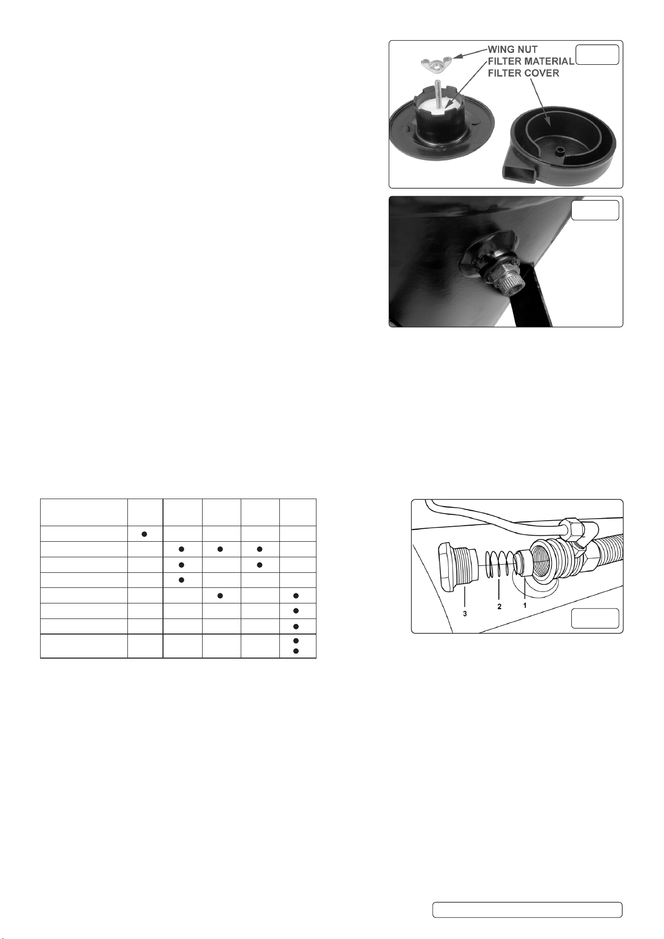
6.2.1. Drain condensation, place a container under the valve and open the valve by
turning anti-clockwise (fig.6). Re-tighten the valve.
6.2.2. Check that all nuts and bolts are tight, particularly those retaining the
crankcase and cylinder heads.
6.3. OPERATIONS TO BE CARRIED OUT EVERY 100 HOURS: (or more
frequently, if the compressor operates in a very dusty atmosphere).
6.3.1. Check oil level and, if necessary, top it up.
6.3.2. Remove the air filter element by unscrewing the air filter holder (fig.5) and
prising open the holder. Clean air filter by blowing through with an air line at
low pressure, from the clean side. Alternatively, wash air filter in soapy water,
rinse and dry. DO NOT operate the compressor without the air filters, as
foreign bodies or dust could seriously damage the pump.
6.3.3. Check for oil leaks.
6.4. OPERATIONS TO BE CARRIED OUT EVERY 500 HOURS:
6.4.1. Replace the lubricating oil. Remove the oil filler/breather (fig.2B) and unscrew
the drain bolt (fig.2C), drain the oil into a suitable container. Drain when the
compressor is hot so that the oil drains rapidly and completely. Incline the
compressor to ensure complete drainage. Replace the drain bolt and refill with
fresh oil through the filler aperture. DO NOT overfill.
6.4.2. Replace oil filler/breather (fig.2B).
6.5. RECOMMENDED OIL:
6.5.1. Suitable for room temperatures ranging from +5ºC to +25ºC: SEALEY CPO or
equivalent SAE 40 compressor oil.
6.5.2. Room temperature below +5ºC: SAE 20 compressor oil.
WARNING! Never mix different oils and DO NOT use non-detergent/low quality oils as the compressor may be damaged.
6.5.3. Dispose of waste oil only in accordance with local authority requirements.
6.5.4. Check the automatic cut-out at maximum pressure and the automatic cut-in at 2 bar below that.
6.5.5. Replace air filter (fig.5).
6.5.6. Check all tube fittings and electrical connections.
IMPORTANT! Failure to carry out maintenance tasks may invalidate the warranty on your compressor.
WARNING-Aircontaminantstakenintothecompressorwillaectoptimumperformance.Example:Bodyllerdustorpaintoverspray
willclogthepumpintakelterandmaycauseinternaldamagetopump/motorcomponents.
NOTE: Any parts damaged by any type of contamination will not be covered by warranty.
6.6. INSPECTION OF PRESSURE TANK BOTH INSIDE AND OUT
6.6.1. Under the PRESSURE SYSTEMS SAFETY REGULATIONS 2000 it is the responsibility of the owner of the compressor to initiate a
system of inspection that both defines the frequency of the inspection and appoints a person who has specific responsibility for carrying
out the inspection.
6.7. SCHEDULED MAINTENANCE TABLE
g.6
MAINTENANCE
Daily 100
Hours
200
Hours
300
Hours
500
Hours
Drain condensation
Check oil level
Cleanairlters
Check for oil leaks
Check cut-out
Replace oil
Replaceairlters
Checktubettingsand
electrical connections
g.7
g.5
Original Language Version
© Jack Sealey Limited SAC5030VA SAC10030VA Issue 4 (3) 24/05/24
Original Language Version
© Jack Sealey Limited SAC5030VA SAC10030VA Issue 4 (3) 24/05/24
Sealey Group, Kempson Way, Suffolk Business Park, Bury St Edmunds, Suffolk. IP32 7AR
01284 757500 sales@sealey.co.uk www.sealey.co.uk
WEEE REGULATIONS
Dispose of this product at the end of its working life in compliance with the EU Directive on Waste Electrical and Electronic
Equipment (WEEE). When the product is no longer required, it must be disposed of in an environmentally protective way. Contact
your local solid waste authority for recycling information.
NOTE: Itisourpolicytocontinuallyimproveproductsandassuchwereservetherighttoalterdata,specicationsandcomponentparts
without prior notice. Please note that other versions of this product are available. If you require documentation for alternative versions, please
email or call our technical team on technical@sealey.co.uk or 01284 757505.
IMPORTANT: No Liability is accepted for incorrect use of this product.
WARRANTY: Guarantee is 12 months from purchase date, proof of which is required for any claim.
ENVIRONMENT PROTECTION
Recycle unwanted materials instead of disposing of them as waste. All tools, accessories and packaging should be
sorted, taken to a recycling centre and disposed of in a manner which is compatible with the environment. When
theproductbecomescompletelyunserviceableandrequiresdisposal,drainanyuids(ifapplicable)intoapproved
containersanddisposeoftheproductanduidsaccordingtolocalregulations.
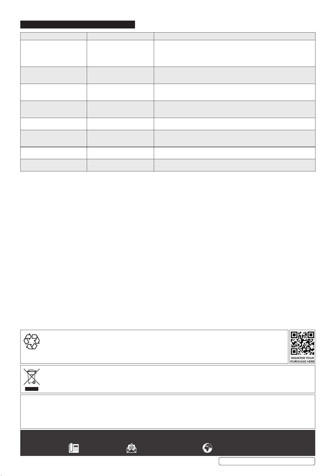
7. TROUBLESHOOTING
FAULT CAUSE REMEDY
Pressure drop in the tank. 1. Air leaks at connections.
2. Air leaks from cylinder head gasket.
1.Runcompressortomaximumpressure,switcho.Brushsoapsolutionover
connections and look for bubbles. Tighten connections showing leaks. If problem
persists, contact Authorised Service Agent.
2. Check tightness of head bolts, if leak continues contact Authorised Service Agent.
Pressure switch valve leaks when
compressor is idle.
Non-return valve seal defective. Emptytheairtank.Referringto(g.7),removethenon-returnvalvecap(g.7.3),spring
(g.7.2)andseal(g.7.1).Cleanthesealanditsseat,orifnecessaryreplacetheseal
andret.
Air leaks from tank body or tank
welds.
Internal corrosion caused by infre-
quent tank draining or non permit-
ted modifications to tank.
Tank could rupture or explode. Cannot be repaired.
DISCONTINUE USE IMMEDIATELY.
Motor stops and will not restart. 1. Thermal cut out has operated.
2. Supply fuse has tripped.
1. Allow unit to cool for 30 minutes then press reset button.
2. Reset fuse and restart unit. If repeated tripping occurs, replace the check valve
or contact Authorised Service Agent.
Compressor stops and will not
restart.
Motor failure. Contact Authorised Service Agent.
Compressor does not stop at
maximum pressure.
1. Pressure switch fault.
2. Filter clogged
3. Head gasket or valve fault
1. Contact Authorised Service Agent.
2. Replace filter element.
3. Contact Authorised Service Agent.
Compressor noisy with metallic
knock.
Bearing or piston damage. Contact Authorised Service Agent.
Excessive moisture in discharged
air.
High humidity environment. Drain tank after each use.