50L/100L OIL FREE V-TWIN DIRECT DRIVE
COMPRESSOR 3HP
MODEL NO’S: SAC05030F/SAC10030F
Thank you for purchasing a Sealey product. Manufactured to a high standard, this product will, if used according to these instructions,
and properly maintained, give you years of trouble free performance.
IMPORTANT: PLEASE READ THESE INSTRUCTIONS CAREFULLY. NOTE THE SAFE OPERATIONAL REQUIREMENTS, WARNINGS & CAUTIONS. USE
THE PRODUCT CORRECTLY AND WITH CARE FOR THE PURPOSE FOR WHICH IT IS INTENDED. FAILURE TO DO SO MAY CAUSE DAMAGE AND/OR
PERSONAL INJURY AND WILL INVALIDATE THE WARRANTY. KEEP THESE INSTRUCTIONS SAFE FOR FUTURE USE.
1. SAFETY
1.1. ELECTRICAL SAFETY
WARNING! It is the user’s responsibility to check the following:
Check all electrical equipment and appliances to ensure that they are safe before using. Inspect power supply leads, plugs and all
electrical connections for wear and damage. Sealey recommend that an RCD (Residual Current Device) is used with all electrical
products. You may obtain an RCD by contacting your local Sealey stockist.
If the product is used in the course of business duties, it must be maintained in a safe condition and routinely PAT (Portable Appliance
Test) tested.
ELECTRICAL SAFETY INFORMATION: it is important that the following information is read and understood.
1.1.1. Ensure that the insulation on all cables and on the appliance is safe before connecting it to the power supply.
1.1.2. Regularly inspect power supply cables and plugs for wear or damage and check all connections to ensure that they are secure.
1.1.3. IMPORTANT: Ensure that the voltage rating on the appliance suits the power supply to be used and that the plug is tted with the
correct fuse - see fuse rating in these instructions.
8 DO NOT pull or carry the appliance by the power cable.
8 DO NOT pull the plug from the socket by the cable.
8 DO NOT use worn or damaged cables, plugs or connectors. Ensure that any faulty item is repaired or
replaced immediately by a qualied electrician.
1.1.4. This product is tted with a BS1363/A 13 Amp 3 pin plug.
If the cable or plug is damaged during use, switch the electricity supply off and remove from use.
Ensure that repairs are carried out by a qualied electrician.
Replace a damaged plug with a BS1363/A 13 Amp 3 pin plug. If in doubt contact a qualied electrician.
A) Connect the GREEN/YELLOW earth wire to the earth terminal ‘E’.
B) Connect the BROWN live wire to the live terminal ‘L’.
C) Connect the BLUE neutral wire to the neutral terminal ‘N’.
Ensure that the cable outer sheath extends inside the cable restraint and that the restraint is tight.
Sealey recommend that repairs are carried out by a qualied electrician.
1.1.5. Products which require more than 13 amps are supplied without a plug. Contact a qualied electrician to ensure that a suitably rated
supply is available. Ensure that an industrial round pin plug and socket are tted by a qualied electrician.
1.1.6. If an extension cable reel is used, ensure that it is fully unwound before connection. Use a reel that includes an RCD, an appliance
will be protected by the RCD. The cable core section is important and should be at least 1.5mm
2
. Ensure that the cable of the reel is
appropriate for this product. We recommend the use of 2.5mm² core section cable.
1.2. GENERAL SAFETY
9 Familiarise yourself with the application and limitations of the compressor.
9 Ensure the compressor is in good order and condition before use. If in any doubt DO NOT use the unit and contact an electrician/service
agent.
WARNING! Compressor must only be serviced by an authorised agent. DO NOT tamper with, or attempt to adjust, pressure switch or
safety valve.
9 Before moving, or maintaining the compressor ensure it is unplugged from the mains supply and that the air tank pressure has been
vented.
9 Maintain the compressor in good condition and replace any damaged or worn parts. Use genuine parts only. Unauthorised parts may be
dangerous and will invalidate your warranty.
Replacement fuse
rating:13A
Refer to
instruction
manual
Wear eye
protection
Wear ear
protection
Warning:
Hot surface
Warning:
Automatic
start-up
Warning:
Electricity
DO NOT open
the air cock
before an air
hose is attached
Indoor
use only
SAC05030F, SAC10030F Issue 2 (H,F) 13/11/20

9 Read the instructions relating to any accessory to be used with this compressor. Ensure the safe working pressure of any air appliance
used exceeds compressors output pressure. If using a spray gun, check that the area selected for spraying is provided with an air change
system/ventilation.
9 Ensure the air supply valve is turned off before disconnecting the air supply hose.
9 To move a transportable compressor use the handle only. Lift the compressor so that the front leg gives enough clearance
for manoeuvring but maintain unit’s centre of gravity in front of the wheels. DO NOT attempt to lift or move the compressor by any other
means.
9 Use the compressor in a well ventilated area and ensure it is placed on a firm surface.
9 Keep tools and other items away from the compressor when it is in use, and keep area clean and clear of unnecessary items.
9 Ensure the air hose is not tangled, twisted or pinched.
9 Keep children and unauthorised persons away from the working area.
8 DO NOT dis-assemble compressor for any reason. The unit must be checked by qualified personnel only.
8 DO NOT use the compressor outdoors, or in damp, or wet, locations.
8 DO NOT operate within the vicinity of flammable liquids, gases or solids.
8 DO NOT touch compressor cylinder, cylinder head or pipe from head to tank as these may be hot.
8 DO NOT use this product to perform a task for which it has not been designed.
8 DO NOT deface the certification plate attached to the compressor tank.
8 DO NOT cover the compressor or restrict air flow around the unit whilst operating.
▲ DANGER! DO NOT direct the output jet of air towards people or animals.
8 DO NOT operate the compressor without an air filter.
8 DO NOT allow anyone to operate the compressor unless they have received full instructions.
WARNING! The air tank is a pressure vessel and the following safety measures apply:
8 DO NOT tamper with the safety valve, DO NOT modify or alter the tank in any way and DO NOT strap anything to the tank.
8 DO NOT subject the tank to impact, vibration or to heat and DO NOT allow contact with abrasives or corrosives.
9 Drain condensation from tank daily and inspect inside walls for corrosion every three months and have a detailed tank inspection carried
out annually. The tank shell must not fall below the certified thickness at any point.
WARNING! If an electrical fuse blows, ensure it is replaced with an identical fuse type and rating.
9 When not in use, store the compressor carefully in a safe, dry, childproof location.
9 When the compressor is not in use it should be switched off, disconnected from the mains supply and the air drained from the tank.
8 DO NOT carry out any welding operations on any pressurised parts of the vessel.
1.3. INSPECTION OF PRESSURE TANK BOTH INTERNAL AND EXTERNAL
1.3.1. Under the Pressure Systems Safety Regulations 2000 it is the responsibility of the owner of the compressor to initiate
a system of inspection that both denes the frequency of the inspection and appoints a person who has specic responsibility for
carrying out the inspection.
2. INTRODUCTION
Oil free V-Twin pump, ideal for applications where an oil free air supply is required. Direct driven pump and brushed electric motor with a safe
and compact design to reduce weight and be more easily transported. Fitted with fully automatic pressure cut-out switch, air regulator and
pressure gauges for tank and supply. Precision welded receiver tank manufactured to meet Pressure Vessel Directive. Supplied with handle and
wheels for manoeuvrability. Fitted with 3-pin plug.
3. SPECIFICATION
MODEL: ................................................................SAC05030F
Air displacement (L/min) ........................................... 11.4 (320)
Max. air delivery (cfm(L/min) .......................................... 8(226)
Max. pressure ........................................................116psi(8bar)
Min. rated supply ................................................................ 13A
Motor output ........................................................................3hp
Outlet ..................................................... quick release coupling
Phase ..................................................................................1ph
Receiver capacity ................................................................50L
Side (W x D x H) ........................................ 790 x 320 x 630mm
Supply .............................................................................. 230V
4. ASSEMBLY
4.1. Fix the wheels by placing the stub axle through the tank bracket as in fig.1.
4.2. Ensure that there is a washer either side of the bracket and tighten the nut.
4.3. The wheel for the SAC10030F is shown. For the SAC05030F: tighten the nut onto the stub axle
as above and tap the hub caps on with a soft faced hammer.
5. OPERATION
WARNING! Ensure that you have read, understood and apply Section 1 safety instructions.
5.1. Take care when selecting tools for use with the compressor. Air tool manufacturers normally
express the volume of air required to operate a tool in cubic feet per minute (cfm). This refers to free air delivered by the compressor
(‘air out’) which varies according to the pressure setting. Do not confuse this with the compressor displacement which is the air taken
in by the compressor (‘air in’). ‘Air out’ is always less than ‘air in’ - due to losses within the compressor.
fig.
1
SAC05030F, SAC10030F Issue 2 (H,F) 13/11/20
MODEL: ................................................................SAC10030F
Air displacement (L/min) ........................................... 11.4 (320)
Max. air delivery (cfm(L/min) .......................................... 8(226)
Max. pressure ........................................................116psi(8bar)
Min. rated supply ................................................................ 13A
Motor output ........................................................................3hp
Outlet ..................................................... quick release coupling
Phase ..................................................................................1ph
Receiver capacity ..............................................................100L
Side (W x D x H) ........................................ 970 x 360 x 765mm
Supply .............................................................................. 230V
Original Language Version
© Jack Sealey Limited
5.2. STARTING THE COMPRESSOR
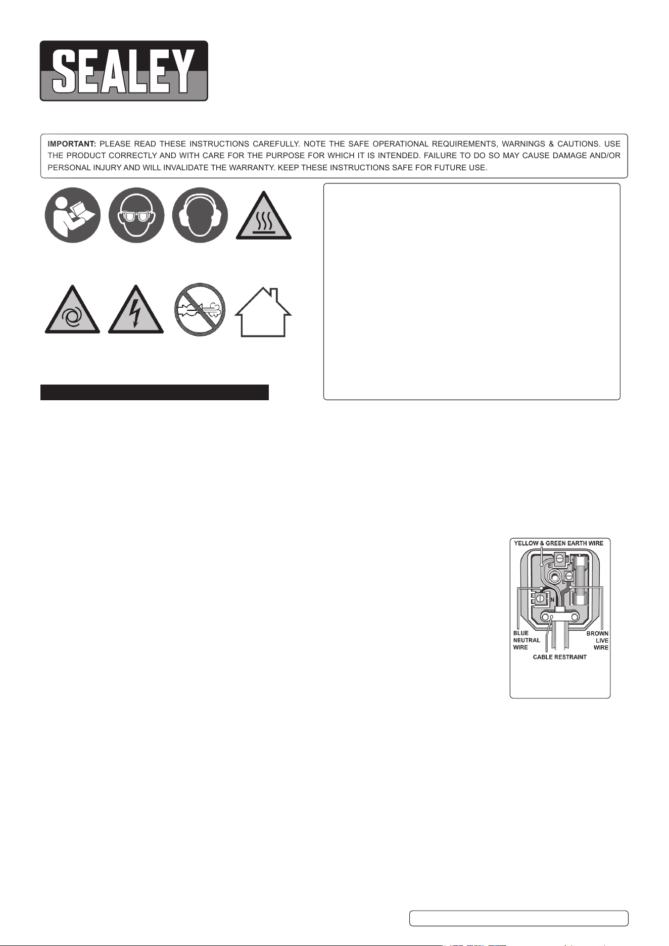
5.2.1. The compressor is tted with a push/pull type of ON/OFF switch (g.2.1).
5.2.2. To turn the compressor ‘ON’ pull the switch knob upwards. To turn the
compressor ‘OFF’ push the switch knob downwards.
5.2.3. Ensure that the regular cap (g.2.3) is turned fully anticlockwise and
no tool is connected to the quick release coupling (g.2.6).
5.2.4. Connect to the electrical supply and start the compressor by pulling
the ON/OFF switch knob upwards.
5.2.5. Leave the compressor running. Make sure that the pressure in the tank
rises and that the compressor stops automatically when the maximum
pressure value allowed - written on the specification plate and shown
on the gauge (fig.2.4) - is achieved. The compressor will now operate
automatically. The pressure switch (fig.2.2) stops the motor when the
maximum tank pressure is reached, and will restart it when pressure
falls below the minimum threshold - approx. 2 bar (29psi) less than the
maximum pressure.
5.2.6. Stop the compressor by pushing the switch knob downwards.
5.2.7. The air inside the cylinder heads will vent, making the restart easier and
preventing the motor from being damaged.
8 DO NOT, other than in an emergency, stop the compressor by switching
off the electrical supply, or by pulling the plug out of the socket, as the
pressure relief will not then occur and motor damage may result upon
restart.
5.2.8. When the compressor runs correctly and is stopped correctly there will be a hiss of compressed air when the motor stops. This is caused
by pressure switch venting the cylinder heads to allow a soft start the next time that the unit runs.
5.2.9. The output pressure is regulated by the pressure regulator cap (fig.2.3). Turn the cap clockwise to increase pressure and anti-clockwise
to reduce it. The output pressure is shown on smaller gauge (fig.2.5) The cap can be locked at any required setting by tightening the
locking ring (fig.2.3a) up against the underside of the tap. To determine the correct working pressure for any piece of equipment check the
corresponding manual. When the compressor is not being used, set the regulated pressure to zero so as to avoid damaging the pressure
regulator.
NOTE: If the motor does not cut in and out, but runs continuously when using an air appliance, the capacity of the compressor
may be too small for the equipment or tool.
The larger gauge (fig.2.4) indicates the pressure inside the main tank. The smaller gauge (fig.2.5) indicates the pressure supplied to
the air equipment. Should the pressure in the main tank exceed the pressure switch maximum, the safety valve to the rear of the
pressure switch (fig.2.7) will activate.
WARNING! For this reason DO NOT tamper with, or adjust, the pressure switch or safety valve.
5.2.10. The compressor is fitted with a thermal overload trip. If the unit stops, switch it off and wait for the motor to cool down before restarting.
If this happens frequently, it suggests that the compressor is not powerful enough for the duty required.
6. MAINTENANCE
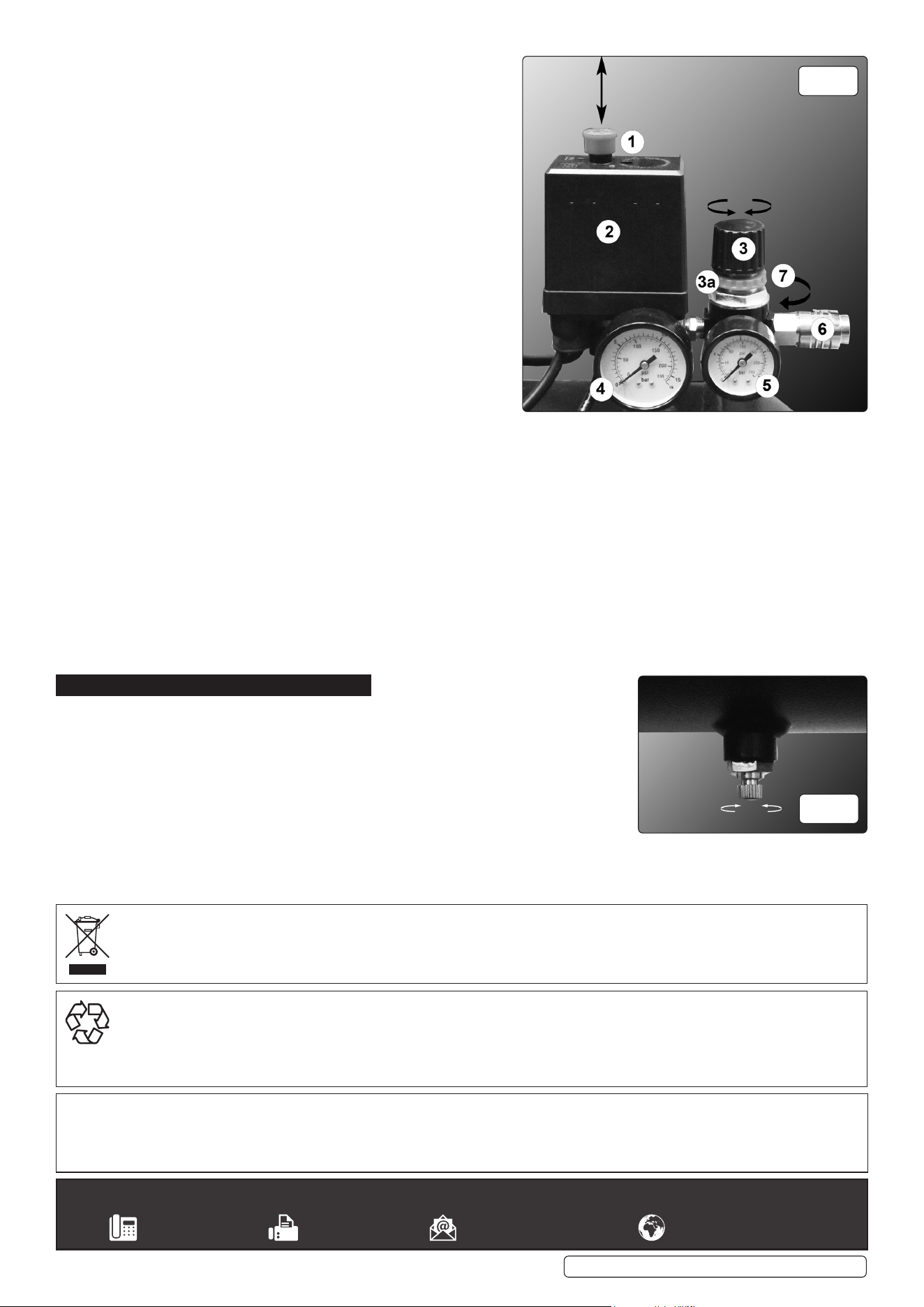
6.1. Drain condensate from the tank on a daily basis.
6.2. Disconnect the machine from the electrical supply and turn the drain tap (fig.3) in an
anticlockwise direction.
6.3. When the air flow is free from condensate, re-tighten the tap.
6.4. To clean: rub over with a damp, soapy cloth. DO NOT use abrasive or solvent cleaners,
6.5. When not in disconnect from the electrical supply, drain the tank and store in a cool, dry,
childproof location.
Sealey Group, Kempson Way, Suffolk Business Park, Bury St Edmunds, Suffolk. IP32 7AR
01284 757500 01284 703534 sales@sealey.co.uk www.sealey.co.uk
ENVIRONMENT PROTECTION
Recycle unwanted materials instead of disposing of them as waste. All tools, accessories and packaging should be sorted, taken to
a recycling centre and disposed of in a manner which is compatible with the environment. When the product becomes completely
unserviceable and requires disposal, drain any fluids (if applicable) into approved containers and dispose of the product and fluids
according to local regulations.
Note: It is our policy to continually improve products and as such we reserve the right to alter data, specifications and component parts without prior
notice.
Important: No Liability is accepted for incorrect use of this product.
Warranty: Guarantee is 12 months from purchase date, proof of which is required for any claim.
WEEE REGULATIONS
Dispose of this product at the end of its working life in compliance with the EU Directive on Waste Electrical and Electronic Equipment
(WEEE). When the product is no longer required, it must be disposed of in an environmentally protective way. Contact your local solid
waste authority for recycling information.
Original Language Version
© Jack Sealey Limited
fig.
2
fig.
2
SAC05030F, SAC10030F Issue 2 (H,F) 13/11/20