EN
Operating and installation instructions M Pure
005311-10001

70 bora.com
Contents
1 General information 72
1.1 Validity of the operating and
installation instructions .....................72
1.2 Liability ...............................................72
1.3 Product conformity ............................72
1.4 Presentation of information...............72
1.4.1 Safety and warning instructions.......... 72
1.4.2 Figures ................................................ 73
2 Safety 74
2.1 Intended use....................................... 74
2.2 People with limited abilities...............74
2.3 General safety instructions................75
2.4 Safety information for installation..... 77
2.4.1 Safety instructions –
cooktop extractor installation ............. 78
2.4.2 Safety information for cooktop
installation .......................................... 79
2.5 Safety instructions – operation.........80
2.5.1 Safety instructions –
cooktop extractor operation ............... 81
2.5.2 Safety instructions –
cooktop operation............................... 82
2.6 Safety instructions –
cleaning and maintenance.................84
2.6.1 Safety instructions – cleaning and
maintenance of cooktop extractors .... 84
2.6.2 Safety instructions – cleaning and
maintenance of cooktops.................... 85
2.7 Safety instructions –
repairs, servicing and spare parts.....85
2.8 Safety instructions –
disassembly and disposal .................. 86
3 Technical data 87
3.1 M Pure................................................. 87
3.1.1 PURMA appliance dimensions............. 87
3.1.2 PURMU appliance dimensions ............ 88
4 Appliance description 89
4.1 Model description............................... 89
4.2 System description ...........................89
4.2.1 Structure............................................. 89
4.2.2 Operating panel................................... 89
4.2.3 Symbols .............................................. 90
4.2.4 7-segment display............................... 90
4.2.5 Lighting ............................................... 91
4.2.6 Sounds................................................ 91
4.3 How the cooktop extractor works.....91
4.4 How the induction cooktop works ....91
5 Functions and operation 93
5.1 General operating instructions..........93
5.2 Touch control......................................93
5.3 Function overview ..............................93
5.4 Operating the system.........................93
5.4.1 Switch on/off...................................... 93
5.4.2 Short-time timer.................................. 94
5.5 Cooktop extractor functions..............94
5.5.1 Setting the fan power levels................ 94
5.5.2 Fan power setting ............................... 94
5.5.3 Automatic extractor function .............. 94
5.5.4 Switching the fan off ........................... 95
5.5.5 Automatic after-run............................. 95
5.5.6 Filter service display ........................... 95
5.6 Cooktop functions ..............................95
5.6.1 Pan size recognition ............................ 95
5.6.2 Selecting a cooking zone .................... 95
5.6.3 Setting cooking zone power levels ...... 95
5.6.4 Cooking zone power setting................ 96
5.6.5 Automatic heat up function................. 96
5.6.6 Cooking zone timer ............................. 96
5.6.7 Pause function .................................... 97
5.6.8 Heat retention function ....................... 97
5.6.9 Bridging function................................. 97
5.6.10 Automatic bridging function................ 97
5.6.11 Switching off the cooking zone ........... 98
5.7 Safety features ...................................98
5.7.1 Child lock ............................................ 98
5.7.2 Operating lock..................................... 98
5.7.3 Cleaning lock ...................................... 98
5.7.4 Residual heat indicator........................ 98
5.7.5 Safety shut-down ................................ 98
5.7.6 Overheating protection ....................... 99
6 User menu 100
6.1 Menu item 1:
volume of the acoustic signals ........100
6.2 Menu item 2: Child lock ...................100
6.3 Menu item 3: Show filter status
and reset filter service display.........101
6.4 Menu item 4: Duration of the
automatic after-run function............101
6.5 Menu item 5:
Touch zone reaction speed ..............101
6.6 Menu item 6: LED test......................102
6.7 Menu item 7:
Permanent pan size recognition ......102
6.8 Menu item 8:
Show software/hardware version...102
6.9 Menu item 9: Safety shut-down.......102
6.10 Menu item A: Super simple mode....103
6.11 Menu item 0:
Reset to factory settings..................103

bora.com 71
7 Cleaning and maintenance 104
7.1 Cleaning agents................................104
7.2 Cooktop and extractor care.............104
7.3 Cleaning the cooktop .......................104
7.4 Cleaning the cooktop extractor.......105
7.4.1 Cleaning the air inlet nozzle and
stainless steel grease filter ............... 105
7.4.2 Removing liquids from the appliance 105
7.5 Cleaning the air guiding housing .....106
7.6 Replace the activated
charcoal filter ...................................106
8 Troubleshooting 109
9 Installation 110
9.1 General installation instructions .....110
9.1.1 Simultaneous operation of the
cooktop extractor in the exhaust air
mode with a fireplace dependent
upon the air supply in the room ........ 110
9.2 Scope of delivery..............................111
9.3 Tools and aids...................................111
9.4 Assembly instructions......................111
9.4.1 Installation clearances ...................... 111
9.4.2 Minimum unit dimensions ................. 111
9.4.3 Information on kitchen units ............. 111
9.5 Worktop cut-out ...............................112
9.5.1 Cut-out dimensions........................... 112
9.6 Installing the appliance in
exhaust air mode..............................112
9.6.1 Preparing kitchen units for the
exhaust air model.............................. 113
9.6.2 Installation dimensions ..................... 113
9.6.3 Preparing the appliance .................... 113
9.6.4 Inserting the cooktop........................ 114
9.6.5 Securing the cooktop........................ 114
9.6.6 Connecting the appliance to the
duct system ...................................... 114
9.7 Installing the appliance in
recirculation mode ...........................115
9.7.1 Recirculation of air from the
kitchen unit....................................... 115
9.7.2 Installation variants (A and B) for
recirculation appliances .................... 115
9.7.3 Preparing the kitchen unit for
installation variant A ........................ 116
9.7.4 Installation dimensions for
installation variant A ......................... 116
9.7.5 Preparing the kitchen unit for
installation variant B ......................... 116
9.7.6 Installation dimensions for
installation variant B ......................... 117
9.7.7 Preparing the appliance .................... 117
9.7.8 Extending the telescopic pull-out of
the air purification box ...................... 117
9.7.9 Inserting the cooktop – recirculation 118
9.7.10 Securing the cooktop........................ 119
9.7.11 Making a connection with the
back panel in installation variant A.... 119
9.7.12 Inserting the activated charcoal filter 119
9.8 Connecting the power supply ..........120
9.9 Initial operation ................................121
9.9.1 Dealer and service menu................... 121
9.9.2 Menu item B: Extraction system
configuration..................................... 122
9.9.3 Menu item C: Power management .... 122
9.9.4 Menu item D: Demo mode ................ 122
9.9.5 Function test..................................... 123
9.10 Sealing the appliance .......................123
9.11 Handover to user..............................123
10 Decommissioning,
disassembly and disposal 124
10.1 Decommissioning .............................124
10.2 Disassembly......................................124
10.3 Environmentally-friendly disposal ...124
10.3.1 Disposal of transport packaging........ 124
10.3.2 Disposal of accessories..................... 124
10.3.3 Disposal of the old appliance ............ 124
11 Warranty, technical service,
spare parts, accessories 125
11.1 BORA manufacturer’s warranty .......125
11.1.1 Warranty extension ........................... 125
11.2 Service ..............................................125
11.3 Spare parts .......................................126
11.4 Accessories.......................................126
12 Product data sheets 127
12.1 PURMA - Cooktop extractor product
data sheet .........................................127
12.2 M Pure - Cooktop product data
sheet .................................................128

General information
EN
72 bora.com
1 General information
These instructions contain important information to
protect you from injury and prevent damage to the
appliance. Please read these instructions carefully
before installing or using the appliance for the first time.
Other documents apply alongside these instructions.
Please by all means adhere to all documents that form
part of the scope of delivery.
Assembly, installation and commissioning must always
occur in line with national laws, regulations and
standards. The work must be performed by qualified
specialists who know and comply with the additional
regulations of the local energy supply companies.
All safety and warning information as well as the
handling instructions in the accompanying documents
must be observed.
Please keep these instructions in a safe place and pass
them on to the next owner where applicable.
1.1
Validity of the operating and
installation instructions
These instructions apply to several appliance versions.
It is therefore possible that some of the features
described do not apply to your appliance. The details of
the figures contained herein may differ from some
appliance versions and are to be understood as
schematic diagrams.
1.2
Liability
. BORA Holding GmbH, BORA Vertriebs GmbH & Co KG,
BORA APAC Pty Ltd and BORA Lüftungstechnik GmbH –
hereinafter referred to as BORA – do not assume any
liability for damage arising from disregard for or non-
adherence to the documents included in the scope of
delivery!
Furthermore, BORA shall not be held liable for damage
caused by improper installation or failure to observe the
safety and warning information!
1.3
Product conformity
Directives
The appliances meet the following EU/EC directives:
T
2014/30/EU EMC Directive
T
2014/35/EU Low Voltage Directive
T
2009/125/EC Ecodesign Directive
T
2011/65/EU RoHS Directive
1.4
Presentation of
information
We use standard formatting, numbering, symbols, safety
instructions, terms and abbreviations so that you can
work quickly and safely when using this manual. The
article described in these instructions is hereinafter also
referred to as an appliance.
Instructions are indicated with an arrow.
u
Always follow all instructions in the prescribed order.
Enumerations are indicated with a bullet point at the
start of the line:
T
Enumeration 1
T
Enumeration 2
Information notes point to special features that
must be taken into account.
1.4.1
Safety and warning
instructions
The safety and warning instructions in this manual are
emphasised with symbols and signal words. Safety and
warning instructions are structured as follows:
ö
DANGER
Type and source of danger
Results of non-compliance
u
Measures to minimise risk
Please note:
T
warning symbols draw attention to a high risk of
injury.
T
The signal word indicates the severity of that risk.
General information
EN
bora.com 73
Warning
symbol
Signal
word
Risk
Danger Indicates an immediate,
hazardous situation which
causes death or serious injury
if not respected.
Warning Indicates a potentially
hazardous situation which can
cause death or serious injury if
not respected.
Caution Indicates a potentially
hazardous situation which can
cause death or serious injury if
not respected.
Note Indicates a potentially
hazardous situation which can
cause property damage if not
respected.
Tab.1.1
Meaning of the warning symbols and signal
words
1.4.2
Figures
All measurements are provided in millimetres.

Safety
EN
74 bora.com
2 Safety
The appliance complies with the stipulated safety requirements. The user is responsible for the safe use of the
appliance, cleaning and maintenance. Improper use can lead to personal injury and damage to property.
2.1
Intended use
The appliance is solely intended for preparing food in private households.
This appliance is not intended for:
T
outdoor use
T
heating rooms
T
cooling, ventilating or dehumidifying rooms
T
use in mobile installation sites such as motor vehicles, ships or aeroplanes
T
use with an external timer or a separate remote control system
T
use at altitudes of over 2000m (metres above sea level)
T
use when not fully installed
Any other use or any use that goes beyond that which is described here is classed as unintended.
BORA does not assume any liability for damages caused by incorrect installation, improper use or incorrect
operation.
All misuse is prohibited!
2.2
People with limited abilities
Children
The appliance can be used by children aged 8 and over if they are supervised or have been instructed how to use the
appliance safely and understand the resultant risks. Children must not play with the appliance.
u
Use the childproofing feature in order to prevent children from switching on the appliance or changing the settings
when they are unattended.
u
Supervise children in the vicinity of the appliance.
u
Do not store any items that could be of interest to children in storage spaces above or behind the appliance.
Otherwise, they will be tempted to climb onto the appliance.
Any work involving cleaning and maintenance must not be carried out by children unless they are
supervised at all times while doing so.
People with reduced physical, sensory or mental capacities
The appliance can be used by people with reduced physical, sensory or mental capacities or a lack of experience
and/or knowledge if they are supervised or have been instructed how to use the appliance safely and understand the
resultant risks. Operation can be restricted using the child lock.

Safety
EN
bora.com 75
ö
DANGER
Risk of burns from hot cookware and food
Handles projecting over the edge of the worktop are asking to be grabbed.
u
Keep children away from hot cooking zones or ensure they are supervised at all times.
u
Do not turn pot and pan handles so they stick out beyond the work surface.
u
Make sure that hot pots and pans cannot be pulled down.
u
If necessary, use suitable stove guards or covers.
u
Only use stove guards and covers that are approved by the appliance
manufacturer; otherwise, there is a risk of accidents.
u
To choose a suitable stove guard, contact your specialist retailer or the
BORA Service Team.
2.3
General safety instructions
ö
DANGER
Packaging components are a choking hazard
Packaging components (e.g. film, polystyrene) can be life-threatening for children.
u
Store all packaging components out of reach of children.
u
Dispose of the packaging properly and immediately.
ö
DANGER
Risk of electric shock or injury from damaged surfaces
The underlying electronics can be exposed or damaged due to fissures, fractures
or cracks in appliance surfaces (e.g. damaged glass), particularly in the vicinity of
the operating unit. This can cause an electrical shock. Furthermore, a damaged
surface can cause injuries.
u
Do not touch the damaged surface.
u
If there are any cracks, fissures or fractures, switch the appliance off immediately.
u
Securely disconnect the appliance from the mains using the circuit breaker,
fuses, automatic circuit breakers or contactor.
u
Contact the BORA Service Team.
ö
WARNING
Risk of injury or damage due to incorrect components or unauthorised
modifications
Incorrect components can lead to personal injury or damage to the appliance.
Modifications, additions or alterations to the appliance can lead to safety risks.
u
Only use original components.
u
Do not make any modifications, additions or alterations to the appliance.

Safety
EN
76 bora.com
ö
WARNING
Risk of injury due to mechanical damage on the appliance
Mechanical damage (e.g. cracks, deformation, separation of adhesive seals,
etc.) to the appliance, as well as to cables and accessories can cause injuries.
u
Do not operate the appliance.
u
Do not try to repair or replace damaged components yourself.
u
Contact the BORA Service Team.
CAUTION
Appliance components can cause injury if dropped
Appliance components can cause injury if you drop them.
u
Place any appliance components that have been removed in a safe place
near the appliances.
u
Ensure that no components removed from the appliances can fall on the floor.
CAUTION
Risk of injury from heavy lifting
If not handled correctly, carrying and installing appliances can cause injury to
the limbs or torso.
u
If necessary, carry and install the appliance with another person.
u
Use appropriate aids to prevent damage or injury.
CAUTION
Damage from improper use
The appliance surfaces must not be used as work or storage surfaces. This can
damage the appliances (particularly in the case of hard and sharp objects).
u
Never use the appliances as work or storage surfaces.
u
Keep hard or sharp objects away from the appliance surfaces.
PLEASE NOTE
Faults and errors
In the event of faults or incorrect use, error messages will be displayed.
u
In the case of faults and errors, follow the instructions in the
“Troubleshooting” chapter.
u
In the event of any faults or errors that are not mentioned, switch the
appliance off and contact BORA Service.

Safety
EN
bora.com 77
PLEASE NOTE
Appliance damage caused by pets
Pets may damage the appliance or injure themselves.
u
Keep pets away from the appliance.
2.4
Safety information for installation
ö
DANGER
Risk of injury from incorrect assembly
Failure to observe the installation instructions can lead to injury.
u
The appliance must only be installed and assembled by trained specialists
who are familiar with and comply with the standard national regulations and
supplementary regulations of the local utility companies.
u
The appliance may only be installed with the power disconnected.
u
Work on electrical components must only be conducted by trained electrical
personnel.
u
Conduct all work extremely attentively and conscientiously.
u
Before handing the appliance or system over to the end user, ensure that it
has been correctly installed.
ö
DANGER
Risk of electric shock from damaged appliance
A damaged appliance can cause an electric shock.
u
Check the appliance for visible damage prior to installation.
u
Do not install or connect any damaged appliances.
u
Do not operate any damaged appliances.
ö
DANGER
Risk of electric shock from incorrect stripping of cables
Incorrect stripping of the connection cable to external switching devices results
in a risk of electric shock.
u
Ensure that the connection cable is secured with the strain relief clamp
within the control unit.
u
Ensure that the stated stripping lengths are adhered to.

Safety
EN
78 bora.com
PLEASE NOTE
Appliance damage caused by incorrect wiring
The electrical safety of the appliance is only guaranteed if it is connected to a
protective conductor system that has been installed in line with regulations.
u
Work on electrical components must only be conducted by trained electrical
personnel.
u
Ensure that this basic safety precaution is met. The appliance must be
suitable for the regional voltage and frequency.
u
Check the information on the identification plate and in the event of
deviations, do not connect the appliance.
u
Do not connect the appliance to the mains until the duct system has been
installed or the recirculation filter has been fitted.
u
Only use the connection cables supplied.
PLEASE NOTE
Appliance damage caused by incorrect installation clearances
Failure to adhere to installation clearances can lead to damage to the appliance
and kitchen units, as well as restricted functions.
u
During installation maintain the minimum clearance stated in the Installation
chapter.
2.4.1
Safety instructions – cooktop extractor installation
ö
DANGER
Risk of smoke inhalation
When the cooktop extractor is used in exhaust air mode, it draws in air from
the room it is installed in and from neighbouring rooms. Without sufficient air,
there will be a drop in air pressure. When used at the same time as a fireplace
that is dependent on the air in the room, noxious gases can be sucked into the
living areas from the chimney or outlet shaft.
u
Make sure that there is always a sufficient air supply.
u
Only use reliable, tried-and-tested switching devices, (e.g. window contact
switch, low pressure warning device) and have them approved by a qualified
expert (certified chimney sweep).

Safety
EN
bora.com 79
ö
WARNING
Risk of injury due to turning fan wheel
There is a risk of injury while the fan is turning.
u
Only install the device with the power disconnected.
u
Connect both sides of the fan to the duct system before commissioning.
CAUTION
Risk of injury due to turning fan wheel
There is a risk of the vicinity of the fan being reached in the case of short air
channels.
u
Never reach through the air outlet into the vicinity of the fan.
u
Always install fans so that it is not possible to touch them via the air outlet.
u
In the case of air channels shorter than 900 mm between the fan and air
outlet, install a guard to prevent access.
u
Activated charcoal filters do not provide sufficient protection.
2.4.2
Safety information for cooktop installation
ö
DANGER
Risk of electric shock from damaged power supply cable
If the power supply cable is damaged (e.g. during installation or by coming into
contact with hot cooking surfaces), this can cause an (lethal) electric shock.
u
Make sure that the connection cable does not become trapped or damaged.
u
Make sure that the power supply cable does not come into contact with hot
cooking surfaces.
ö
DANGER
Risk of electric shock from incorrect mains connection
Connecting the appliance to the mains incorrectly poses a risk of electric
shock.
u
Make sure that the appliance has a fixed connection to the mains voltage.
u
Make sure that the appliance is connected to a properly installed protective
conductor system.
u
Make sure that technical equipment is provided to enable all of the
appliance’s poles to be disconnected from the mains with a contact opening
width of at least 3mm (circuit breaker and automatic circuit breakers, fuses,
contactor).

Safety
EN
80 bora.com
2.5
Safety instructions – operation
ö
DANGER
Risk of fire from overheated oil or fat
Oil or fat in the pot can quickly heat up and ignite.
u
Never leave the appliance unattended when cooking with oil or fat.
u
Never extinguish oil and fat fires with water.
u
Switch off the appliance.
u
Extinguish the fire using a pan lid or a fire blanket, for example.
ö
WARNING
Risk of burning from hot appliances
Certain appliances and their exposed parts become hot during use. They
should be left to cool down completely after switching off. Touching hot
surfaces can cause serious burns.
u
Do not touch hot appliances.
u
Pay attention to the residual heat indicator.
ö
WARNING
Risk of burns due to power cut
During or after a power cut a cooktop that was previously in operation may still
be hot.
u
Do not touch the appliance while it is still hot.
u
Keep children away from the hot appliance.
ö
WARNING
Risk of burning and fire from hot objects
The appliance and its exposed parts are hot during operation and the cooling
phase. Objects in contact with hot appliance components heat up very quickly
and can cause severe burns (this particularly applies to metal objects such as
knives, forks, spoons, lids or appliance components) or catch fire.
u
Do not place any items on the appliance.
u
Please use suitable accessories (pot holders, oven gloves).
u
Do not simply rely on the pan size recognition function on induction
cooktops; always switch the appliance off after use.

Safety
EN
bora.com 81
CAUTION
Damage caused by hot cookware
Hot cookware can damage certain components in the appliance.
u
Do not put hot cookware down in the area of the operating panel or cooktop
display.
u
Keep hot cookware away from the air inlet nozzle.
PLEASE NOTE
Appliance damage
Incorrect use may cause damage to the appliance.
u
Make sure that the base of the cookware as well as the appliance surfaces
are clean and dry.
u
Always lift (do not drag) cookware to prevent scratching and abrasion on the
appliance surface.
u
Do not use the appliance as a storage surface.
u
Always switch off the appliance after use.
2.5.1
Safety instructions – cooktop extractor operation
ö
DANGER
Risk of smoke inhalation
When the cooktop extractor is used in exhaust air mode, it draws in air from
the room it is installed in and from neighbouring rooms. Without sufficient air,
there will be a drop in air pressure. When used at the same time as a fireplace
that is dependent on the air in the room, noxious gases can be sucked into the
living areas from the chimney or outlet shaft.
u
Make sure that there is always a sufficient air supply.
u
Only use reliable, tried-and-tested switching devices, (e.g. window contact
switch, low pressure warning device) and have them approved by a qualified
expert (certified chimney sweep).
ö
WARNING
Fire risk from flambéing
While the cooktop extractor is working, it sucks up grease from cooking.
Flambéing food can cause the grease to catch fire.
u
Clean the cooktop extractor regularly.
u
Never work with a naked flame while the cooktop extractor is running.

Safety
EN
82 bora.com
CAUTION
Damage caused by objects or paper suctioned in
Small and light items, such as cleaning cloths made from material or paper, can
be suctioned into the cooktop extractor. This can damage the fan or impair the
exhaust performance.
u
Do not store any items or paper on the cooktop extractor.
u
Only operate the integrated cooktop extractor with the grease filter fitted.
CAUTION
Damage caused by grease and dirt deposits
Grease and dirt deposits can prevent the cooktop extractor from functioning
properly.
u
Never use the cooktop extractor without a correctly fitted stainless steel
grease filter.
PLEASE NOTE
Increased humidity
When cooking, additional moisture is released into the ambient air. In
recirculation mode, only a slight amount of moisture is removed from the
cooking vapour.
u
When using the recirculation mode, ensure a sufficient supply of fresh air,
e.g. by opening a window.
u
Ensure a normal and comfortable room climate (humidity of 45 – 60%), e.g.
by opening natural ventilation openings or using domestic ventilation
systems.
2.5.2
Safety instructions – cooktop operation
ö
DANGER
Danger of fire caused by leaving the cooktop unattended
Oil or fat in the pot can quickly heat up and ignite.
u
Never leave oil or fat to heat up unattended.
u
Never extinguish oil and fat fires with water.
u
Switch off the cooktop.
u
Extinguish the fire using a pan lid or a fire blanket, for example.

Safety
EN
bora.com 83
ö
DANGER
Danger of explosion caused by flammable liquids
Flammable liquids in the vicinity of a cooktop can explode and cause serious
injury.
u
Do not spray aerosols near the appliance when it is in use.
u
Do not place any flammable liquids in the vicinity of a cooktop.
ö
WARNING
Risk of burns from hot liquids boiling over
Unattended pans can boil over allowing hot liquids to escape.
u
Keep an eye on pans when cooking.
u
Avoid over-cooking.
u
Always switch off the appliance after use.
ö
WARNING
Risk of burns from hot steam
Liquid between the cooking zone and cookware base can evaporate and cause
burns.
u
Make sure that the cooking zone and the cookware base are always dry.
PLEASE NOTE
Damage caused by sugary and salty foods
Sugary and salty foods and juices can damage the hot cooking zone.
u
Make sure sugary and salty foods or juices do not get onto the cooking zone
while it is hot.
u
Remove sugary and salty foods and juices from the hot cooking zone
immediately.
CAUTION
Electromagnetic radiation
Effect on pace makers, hearing aids and metal implants. Induction cooktops
generate a high-frequency electromagnetic field in the area of the cooking
zones. The cooking zones may affect pacemakers, hearing aids or metal
implants negatively or disturb their function when in close proximity.
u
If in doubt, contact the manufacturer of your medical device or your doctor.

Safety
EN
84 bora.com
2.6
Safety instructions – cleaning and maintenance
PLEASE NOTE
Appliance damage due to soiled appliances
Dirt can lead to damage, restriction of functions, or bothersome odours.
u
Clean the appliance regularly.
u
Remove dirt immediately.
u
When cleaning, only use non-abrasive detergents to prevent scratching and
abrasion on the surface.
u
When cleaning, ensure that no water penetrates the appliance. Use only a
slightly damp cloth. Never spray the appliance with water. Water penetration
can cause damage.
u
Do not use a steam cleaner for cleaning. Steam can cause a short circuit on
live parts and thus lead to property damage.
u
Please follow all instructions in the “Cleaning and Maintenance” chapter.
2.6.1
Safety instructions – cleaning and maintenance of cooktop extractors
ö
DANGER
Risk of fire from fat deposits
The risk of fire can be increased by failure to clean the grease filter properly
and on a regular basis, or if the filter change is overdue.
u
Clean and replace the filter at regular intervals.
ö
WARNING
Risk of injury when opening the bottom housing cover
There is a risk of injury while the fan is turning.
u
Switch off the appliance and disconnect it from the mains before removing
covers in the vicinity of the fan.
ö
WARNING
Risk of injury due to turning fan wheel
If the fan wheel is turning during a filter change, this may result in injuries.
u
Ensure that the appliance is switched off before changing the activated
charcoal filter.

Safety
EN
bora.com 85
PLEASE NOTE
Appliance damage and malfunctions
Soiled ventilation openings can lead to component damage and malfunctions.
u
Keep all ventilation openings open and clean.
2.6.2
Safety instructions – cleaning and maintenance of cooktops
ö
WARNING
Risk of burns from hot surfaces
There is a risk of burns when cleaning hot cooktops.
u
Only clean the cooktops once they have cooled.
u
Pay attention to the residual heat indicator.
2.7
Safety instructions – repairs, servicing and spare parts
ö
DANGER
Risk of injury when carrying out repairs
Insufficient expertise can lead to injury when carrying out repairs.
u
The appliance must only be repaired and serviced by trained specialists who
are familiar with and comply with the standard national regulations and
supplementary regulations of the local utility companies.
u
Safely disconnect the appliance from the mains supply.
u
Work on electrical components must only be conducted by trained electrical
personnel.
u
A damaged power supply cable must be replaced by a suitable power supply
cable.
ö
WARNING
Risk of injury or damage from improper repairs
Incorrect components can lead to personal injury or damage to the appliance.
Modifications, additions or alterations to the appliance can lead to safety risks.
u
Only use original spare parts for repairs.
u
Do not make any modifications, additions or alterations to the appliance.

Safety
EN
86 bora.com
2.8
Safety instructions – disassembly and disposal
ö
DANGER
Risk of injury during disassembly
Insufficient expertise can lead to injury when disassembling the appliance.
u
It must only be disassembled by trained specialists who are familiar with and
comply with the standard national regulations and supplementary
regulations of the local utility companies.
u
Safely disconnect the appliance from the mains supply.
u
Work on electrical components must only be conducted by trained electrical
personnel.
ö
DANGER
Risk of electric shock from incorrect disconnection
Incorrectly disconnecting the appliance from the mains results in a risk of
electric shock.
u
Safely disconnect the appliance from the mains supply.
u
Use an authorised measuring device to ensure that there is no power to the
appliance.
u
Do not touch exposed contacts on the electronic unit as they may contain
residual charge.
ö
DANGER
Risk of electric shock from residual charge
Electrical components in the appliance can contain residual charge and cause
an electric shock.
u
Do not touch any exposed contacts.
Technical data
EN
bora.com 87
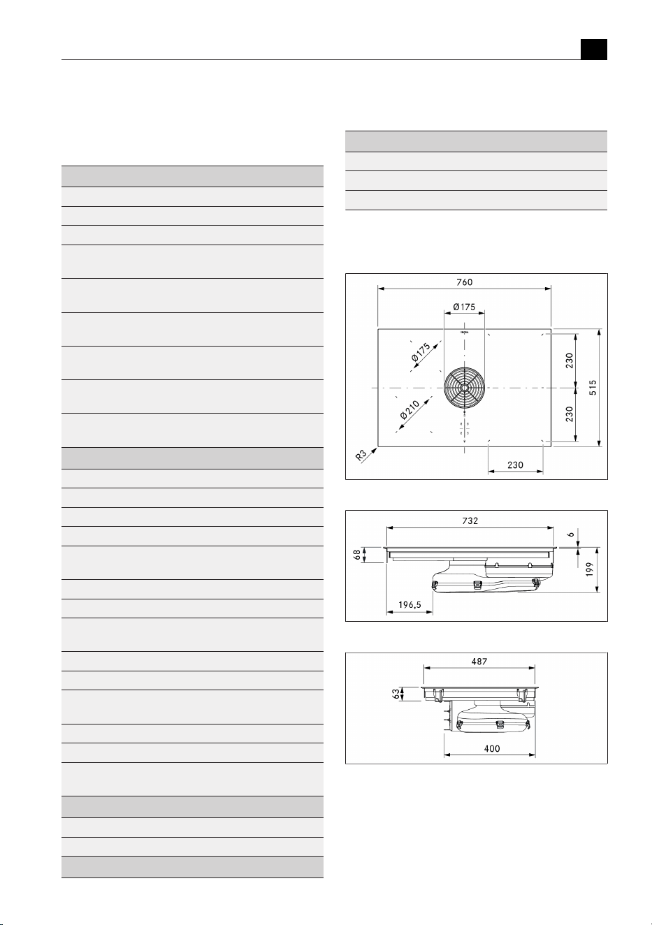
3 Technical data
3.1
M Pure
Parameter Value
Multiphase supply voltage 380–415 V 2N/3N
Single-phase supply voltage 220–240V
Frequency 50–60 Hz
Maximum power consumption 7600W
(4400W/3600W)
Three-phase power supply/
fuse protection
3 x 16 A
Two-phase power supply/
fuse protection
2 x 16A
Single-phase power supply/
fuse protection
1 x 32 A
(1 x 20 A /1 x 16 A)
Dimensions
(width x depth x height)
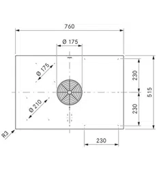
760 x 515 x 199 mm
Weight
(incl. accessories/packaging)
21.8 kg (PURMA)
23.6 kg (PURMU)
Cooktop
Surface material Glass ceramic
Cooktop power levels 1–9, P
Front left cooking zone size Ø 210 mm
Front left cooking zone output 2300 W
Front left cooking zone
power setting output
3000 W
Rear left cooking zone size Ø 175 mm
Rear left cooking zone output 1400 W
Rear left cooking zone
power setting output
2100 W
Front right cooking zone size 230 x 230 mm
Front right cooking zone output 2100 W
Front right cooking zone
power setting output
3000 W
Rear right cooking zone size 230 x 230 mm
Rear right cooking zone output 2100 W
Rear right cooking zone
power setting output
3000 W
Exhaust air system
Cooktop extractor power levels 1–9, P
Exhaust air connection BORA Ecotube
Recirculation system
Parameter Value
Cooktop extractor power levels 1–9, P
Size of exhaust opening (W x H) 445 x 137 mm
Activated charcoal filter service life 150 hrs (1 year)
Tab.3.1
Technical data for M Pure
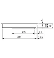
3.1.1
PURMA appliance dimensions
Fig.3.1
PURMA appliance dimensions top view
Fig.3.2
PURMA appliance dimensions front view
Fig.3.3
PURMA appliance dimensions side view
Technical data
EN
88 bora.com
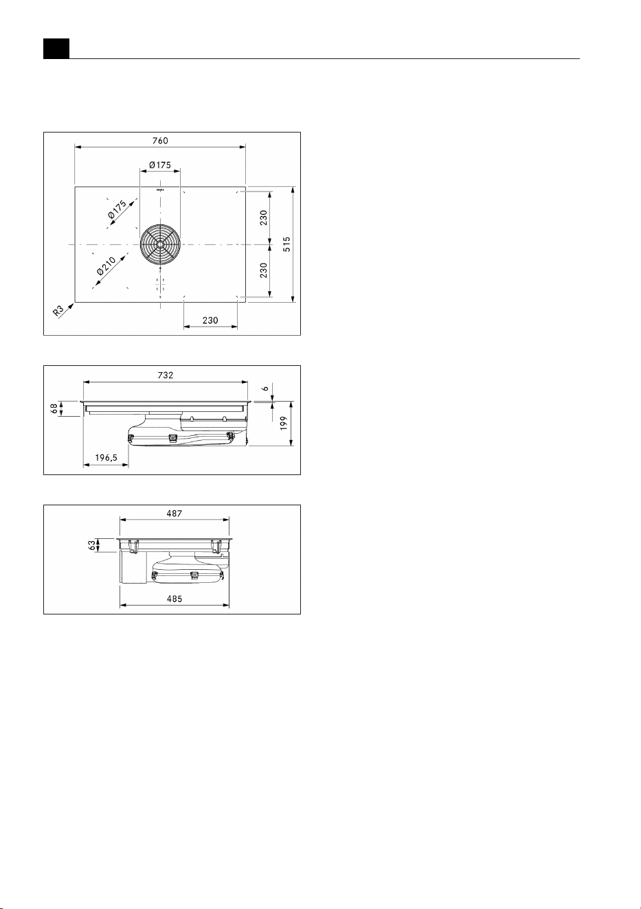
3.1.2
PURMU appliance
dimensions
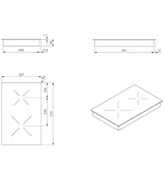
Fig.3.4
PURMU appliance dimensions top view
Fig.3.5
PURMU appliance dimensions front view
Fig.3.6
PURMU appliance dimensions side view
Appliance description
EN
bora.com 89
4 Appliance description
u
Observe all safety and warning information
(see"2Safety").
4.1
Model description
Model Long description
PURMA
M Pure induction/surface induction cooktop
with integrated cooktop extractor – exhaust air
PURMU
M Pure induction/surface induction cooktop
with integrated cooktop extractor – recirculation
Tab.4.1
Model description
Layout and technology:
2 left cooking zones = induction
2 right cooking zones = surface induction
4.2
System description
4.2.1
Structure
1
2
3
4
5
6
7
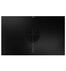
Fig.4.1
Structure
[1] Air inlet nozzle
[2] Stainless steel grease filter
[3] Cooktop
[4] Inlet opening
[5] Fans
[6] Operating panel
[7] Cooking zone (x 4)
1
2
Fig.4.2
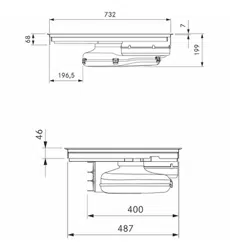
Exhaust air variant rear view
[1] Exhaust opening
[2] Air guiding housing with housing base
1
2
Fig.4.3
Recirculation variant rear view
[1] Air purification box with telescopic pull-out
[2] Air guiding housing with housing base
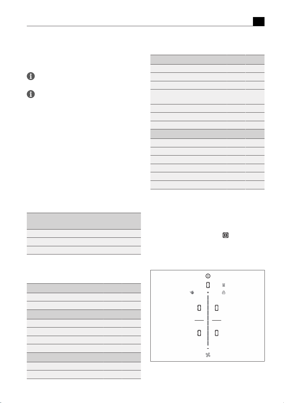
4.2.2
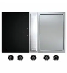
Operating panel
The appliance is operated via a central touch operating
panel.
Fig.4.4
Central touch operating panel with touch
slider
Appliance description
EN
90 bora.com
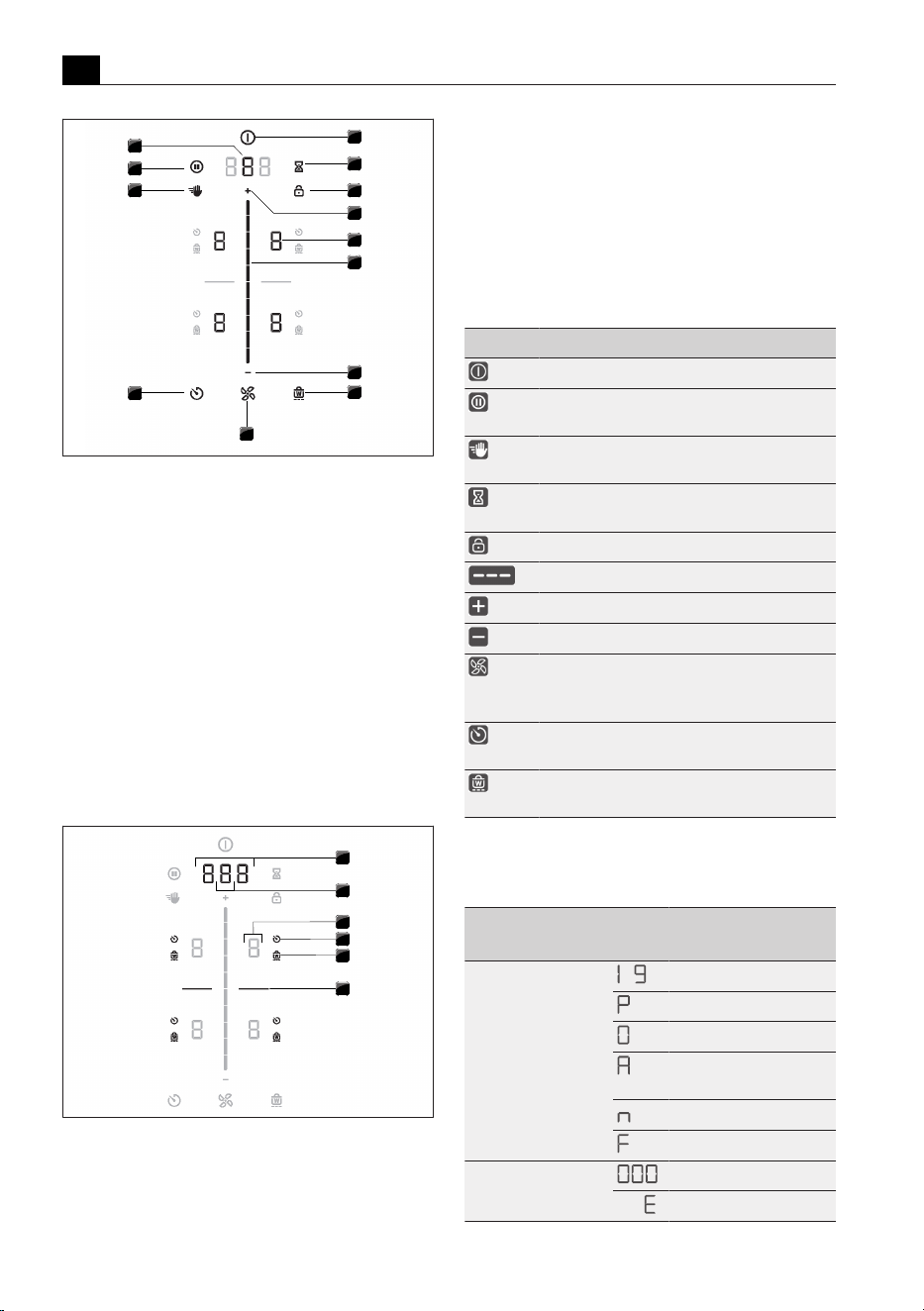
1
2
3
4
5
6
7
8
9
10
11
12
13
Fig.4.5
Touch zones/buttons
[1] Switching on/off
[2] Short-time timer (egg timer)
[3] Operating lock
[4] Plus setting area
[5] Cooking zone selection (x 4)
[6] Touch slider (setting area)
[7] Minus setting area
[8] Heat retention function
[9] Fan functions
[10] Cooking zone timer
[11] Cleaning lock
[12] Pause function
[13] Select fan/Call up menu
1
2
3
4
5
6
Fig.4.6
Indicator zones
[1] Multi-function display
[2] Fan display
[3] Cooking zone indicator (x 4)
[4] Cooking zone timer indicator (x 4)
[5] Heat retention function indicator (x 4)
[6] Dividing line
4.2.3
Symbols
Symbol Designation Function/meaning
Power button Switching on/off
Pause button Pause function
activation/deactivation
Cleaning button Cleaning lock
activation/deactivation
Short-time timer
button
Setting the short-time timer
(egg timer)
Lock button Control lock
Slider Setting values
Plus button Increasing values
Minus button Decreasing values
Fan button Automatic extractor function
activation/deactivation,
Accept after-run function
Timer button Setting the cooking zone
timer
Warming button Heat retention function
activation/deactivation
Tab.4.2
Meaning of the symbols displayed (icons)
4.2.4
7-segment display
Multi-function
display
Meaning
Fan display
‑
Power levels
Power setting
Inactive
Automatic extractor
function
Automatic after-run
Filter service display
Multi-function display Time indication
e.g.
Error code
Appliance description
EN
bora.com 91
Multi-function
display
Meaning
Cooking zone indicator Meaning
Cooking zone
indicator
‑
Power level
Power setting
Heat retention level
Pan size recognition
Inactive
Residual heat indicator
(cooking zone is switched
off but still hot)
Error
Tab.4.3
Meaning of the 7-segment displays
4.2.5
Lighting
The lighting of the displays (bright or dark) is
automatically adapted by the appliance to the
current operating conditions. Unavailable
functions are faded out.
Lighting Use
100% Function is active and selected
50% Function is inactive and can be selected
0% Function is unavailable
Tab.4.4
Lighting
4.2.6
Sounds
The volume of the acoustic signals can be set in
the menu.
The system distinguishes between different signal
acoustic signals:
Acoustic signal Purpose
Short beep (0.25 s ) Confirmation of a selection
Sequence of beeps Interaction required
Tab.4.5
Sounds
4.3
How the cooktop
extractor works
The cooktop extractor is either operated as an exhaust
air system or recirculation system.
Exhaust air operating mode
The cooking vapour is guided by the fan into the open
air via the duct system.
Recirculation operating mode
The cooking vapour is guided by the fan into the
activated charcoal filter and the air cleaned in this way
is released back into the room.
For health and hygiene reasons, the activated charcoal
filter must be replaced at the recommended intervals
(Cleaning and maintenance).
In recirculation mode, ensure sufficient
ventilation and aeration to expel humidity.
4.4
How the induction
cooktop works
Induction cooking zones heat the cookware via a
magnetic field. The pot base is heated directly. The
cooking zone is only heated indirectly. Cooking zones
featuring induction technology only work with suitable
cooking cookware (magnetisable base). Only the
surface that is covered by the pot base will be heated.
Power levels
The high power output of induction cooktops results in
the very quick heating up of cookware. In order to avoid
burning food, slight adjustment is needed in comparison
to conventional cooking systems when selecting the
power level.
Activity Power level
Melting butter and chocolate, breaking
up gelatine
Keeping sauces and soups warm,
soaking rice
-
Cooking potatoes, pasta, soups and
ragouts, steaming fruit, vegetables and
fish, defrosting food
-
Frying in coated pans, moderate frying
(without overheating the fat) of pork
cutlets or fish
-
Heating up fat, browning meat, cooking
thickened sauces and soups, making
omelettes
-
Bringing large amounts of liquid to the
boil, searing steaks
Heating up water
Tab.4.6
Recommendations for power levels
Appliance description
EN
92 bora.com
The specifications provided in the table are standard
values. Depending on the cookware and filling quantity,
it is recommended to either decrease or increase the
power level.
Suitable cookware
Cookware with this symbol is suitable for induction
cooktops.
Suitable cookware is made of:
T
stainless steel with a magnetisable base
T
enamelled steel
T
cast iron
u
Observe the minimum cookware base diameter:
Appliance Cooking zone Minimum cookware
base diameter
M Pure Front left 120 mm
Rear left 90 mm
Front right 120 mm
Rear right 120 mm
Tab.4.7
Minimum cookware diameter
u
Perform a magnet test, if necessary. If a magnet
sticks to the base of the utensils, they are normally
induction compatible.
u
Place the cookware (without a mat or similar) directly
onto the glass ceramic.
The heating and heat-through times and
cooking results are significantly influenced by
the structure and material of the cookware.
The cookware base must not be warped or have
any sharp grooves or sharp edges. If the base is
warped, the cookware may not be recognised or
may overheat. Sharp grooves or edges may
scratch the cooktop surface.
Noises
When operating induction cooktops, noises may occur
due to material and processing of the cookware
(humming, crackling, whistling, clicking or buzzing).
Functions and operation
EN
bora.com 93
5 Functions and operation
u
Observe all safety and warning information
(see"2Safety").
The integrated cooktop extractor must not be
used with other cooktops.
The appliance should only be operated when the
filter replacement cover, stainless steel grease
filter and air inlet nozzle are installed (as well as
the activated charcoal filter in the recirculation
model).
5.1
General operating
instructions
The appliance is operated via a central touch operating
panel. The operating panel is equipped with touch zones
and display zones. Operate the appliance with your finger,
touch controls and swipe gestures (slider operation).
5.2
Touch control
The system recognises different touch commands.
Touch
commands
Applicable to Time (contact)
Tap Buttons + slider 0.3 s
Long press Buttons + slider 1–8 s
Swipe Slider 0.1–8 s
Tab.5.1
Touch control
5.3
Function overview
Features PURMA PURMU
Electronic power adjustment 3 3
Short-time timer (egg timer) 3 3
Cooktop extractor functions
Automatic extractor function 3 3
Automatic after-run 3 3
Power setting 3 3
Filter service display 3
Cooktop functions
Automatic heat up function 3 3
Pan size recognition 3 3
Features PURMA PURMU
Permanent pan size recognition 3 3
Heat retention function 3 3
Bridging function (right cooking zone) 3 3
Automatic bridging function (right
cooking zone)
3 3
Cooking zone timer 3 3
Pause function 3 3
Power setting 3 3
Safety features
Child lock 3 3
Operating lock 3 3
Cleaning lock 3 3
Residual heat indicator 3 3
Safety shut-down 3 3
Overheating protection 3 3
Tab.5.2
Function overview
5.4
Operating the system
5.4.1
Switch on/off
u
Long press on the power button .
Switching on the system:
After start-up, the standard display will appear in the
operating panel:
Fig.5.1
Standard display after switching on
Functions and operation
EN
94 bora.com
When the child lock is active, the lock button
lights up after system start
.
After switching off:
If the cooktop was switched on, after switching it off the
fan’s after-run function will start. The display goes out
when the after-run time has lapsed.
If the cooktop was switched on and there are cooking
zones that are still hot, the residual heat indicator
will
be displayed
zones. The display goes out when no more
residual heat is present.
5.4.2
Short-time timer
The short-time timer emits both a visual and an acoustic
signal after a time set by the user and provides the
function of a conventional egg timer.
Activating the short-time timer
u
Tap the short-time timer button .
The time flashes in the multi-function display above the
slider in minutes (
).
Setting the time
u
Set the desired time:
Command Increase time Decrease time
Swipe
upwards downwards
Tap
(exact to the
minute)
(exact to the
minute)
Tab.5.3
Setting the time
T
The short-time timer button begins to flash.
Starting the short-time timer
u
Tap the flashing short-time timer button .
The set time starts to count down. The remaining time
is shown on the multi-function display.
Time lapsed
In the last 10 seconds of the countdown, the remaining
time will flash and is displayed down to the second. In
the last 5 seconds you will hear a sound.
Deactivating the short-time timer early
u
Long press on the short-time timer button .
If the appliance is switched off, the short-time
timer will remain active.
5.5
Cooktop extractor
functions
5.5.1
Setting the fan power levels
The fan power levels can be adjusted in different ways:
u
by tapping or
u
adjustment using the slider
u
by tapping a certain position on the slider
5.5.2
Fan power setting
When the power setting is activated, maximum extractor
power is available for a predefined time. After 5
minutes, the power setting is automatically switched
back to power level 9.
Activating the fan power setting
u
Tap when power level 9 is active.
T
appears in the fan display.
Deactivating the fan power setting
The fan power setting is deactivated early if another
power level is set.
5.5.3
Automatic extractor function
The extractor power is automatically adjusted to the
highest power level used on all cooking zones that are
currently in use.
T
If the cooking zone power level is changed, the
extractor power is automatically adjusted. The
extractor power is adjusted after a 20 second delay.
Function Power levels
Cooking level 1 2 3 4 5 6 7 8 9 P
Extractor power 4 4 4 4 5 6 7 8 9 P
Tab.5.4
Extractor power when automatic extractor
function is active
Activating the automatic extractor function for
a cooking session:
u
tap the fan button .
T
is displayed.
Deactivating the automatic extractor function:
u
Swipe to a fan power level.
or
u
tap the fan button .
Functions and operation
EN
bora.com 95
5.5.4
Switching the fan off
Switching the fan off
u
Swipe downwards to power level 0
or
u
tap until power level 0 is reached
or
u
long press on the fan button
or
u
Long press on the fan power level in the multi-
function display.
T
When the extractor is switched off, the automatic
after-run function is activated.
5.5.5
Automatic after-run
The cooktop extractor continues to run at a lower level
and switches off automatically after a defined time. The
duration of the after-run function can be set in the
menu (factory setting is 20 minutes).
Switching off the automatic after-run early
u
Long press on the fan button
BORA expressly recommends use of the
cooktop extractor after-run function.
5.5.6
Filter service display
The cooktop extractor filter service display is
automatically activated when the end of the activated
charcoal filter service life is reached (only in
recirculation mode).
T
is displayed in the multi-function display.
T
The filter service display is shown every time the
cooktop extractor is switched on and remains active
until the filter has been changed and the filter service
display has been reset (see"6.3Menu item 3: Show
filter status and reset filter service display").
T
The cooktop extractor can still be operated without
limitations.
The components of the grease filter require
regular cleaning regardless of the filter service
display, see “8 Cleaning and Maintenance”.
5.6
Cooktop functions
5.6.1
Pan size recognition
On induction cooktops the cooking zone recognises the
size of the cookware automatically and only targets the
energy at that area. An induction cooking zone is not
working if the display alternates between
/ .
Possible causes:
T
Missing cookware
T
Unsuitable cookware
T
The base diameter of the cookware is too small
If no pot is detected 10 minutes after setting a power
level, the cooking zone will switch off automatically.
Permanent pan size recognition
The appliance automatically recognises cookware and
activates the corresponding cooking zone controls.
Manual selection of the cooking zone is not necessary
(see"6.7Menu item 7: Permanent pan size
recognition").
Do not simply rely on the pan size recognition
function on induction cooktops; always switch
the appliance off after use.
5.6.2
Selecting a cooking zone
u
Tap the cooking zone display.
The cooking zone operation is activated and settings
can be changed for 2 seconds.
5.6.3
Setting cooking zone power
levels
After selecting the cooking zone, the power level can be
set in 3 different ways:
u
by swiping until you reach the required power level
or
u
by tapping a certain position on the slider
or
u
by tapping or .
Repeat this process to operate further cooking zones if
necessary.
The power level set is shown in the respective
cooking zone display.
Two seconds after the power level is changed,
the operating panel display automatically
returns to the standard display.
Functions and operation
EN
96 bora.com
5.6.4
Cooking zone power setting
When the power setting is activated, maximum cooking
zone power is available for a cooking zone. After 5
minutes, the power setting is automatically switched
back to power level 9. For the second cooking zone on
the same side, the maximum power is temporarily
lowered to power level 7.
If the power setting is set too high for the
second cooking zone, the power setting will be
automatically reset to power level 9 for the
other cooking zone.
Activating the power setting for a cooking zone
u
Tap when power level 9 is active.
T
appears in the cooking zone display.
Deactivating the power setting early
u
Setting another power level
Never heat up oil, fat and the like on the power
setting. The bottom of the pan can overheat due
to the high power output.
5.6.5
Automatic heat up function
When the automatic heat up function is activated, the
cooking zone works at full power for a certain amount
of time and is then automatically reset to the previously
set level.
Power level Cooking duration in
min:sec.
0:40
1:00
2:00
3:00
4:20
7:00
2:00
3:00
Tab.5.5
Heating time overview
Activating the automatic heat up function
Prerequisite: Cooking zone is active (power level is set)
u
Long press on the slider at a position lower
than power level 9
T
Whilst the automatic heat up function is active, the
power level displayed will flash.
Deactivating the automatic heat up function
early
u
Setting a lower power level
If the power level is increased while the
automatic heat up function is active, the heat
up function is automatically adjusted.
5.6.6
Cooking zone timer
This automatic cut-off function automatically switches
off the selected cooking zone once a preset time has
lapsed. The timer function can also be used on several
cooking zones at the same time (multi-timer).
Activating cooking zone timers
Prerequisite: Cooking zone is active (power level is set)
u
Tap the timer button .
T
The time flashes in the multi-function display above
the slider in minutes (
).
Setting the time
u
Set the desired time:
Command Increase time Decrease time
Swipe
upwards downwards
Tap
(exact to the
minute)
(exact to the
minute)
Tab.5.6
Setting the time
Start timer
u
Tap the flashing timer button
The set time starts to count down. The remaining time
is shown on the multi-function display.
Showing the remaining time
u
Tap the cooking zone display with an active timer
T
The remaining time is shown in the multi-function
display.
Changing active timers
u
Tap the cooking zone display with an active timer
u
Tap the timer button
T
The timer is stopped.
T
The remaining time flashes in the display.
u
Change the set time and restart the timer.
Multi-timer
u
Repeat the process for additional cooking zones.
Functions and operation
EN
bora.com 97
Switching the timer off early
u
Tap the cooking zone display with an active timer
u
Long press on the timer button
or
u
long press on the cooking zone display with an active
timer
T
The cooking zone remains active on the set power level.
Time lapsed
In the last 10 seconds of the countdown, the remaining
time will flash and is displayed down to the second. In
the last 5 seconds you will hear a sound.
At the end of the set time the cooking zone is
automatically deactivated (= power level
).
5.6.7
Pause function
With the pause function all cooking zones can be
quickly and easily deactivated temporarily. The cooking
processes can be interrupted for a maximum of
10 seconds. If the pause function is deactivated,
operation will resume with the original settings. Once
10 minutes have lapsed, the cooking session is
automatically ended.
The fan function, the bridging function and the
(active) minute minder cannot be interrupted.
Active cooking zone timers are stopped.
Activating the pause function
u
Tap the pause button
Deactivating the pause function
u
Long press the pause button
5.6.8
Heat retention function
The heat retention function enables meals that have
already been cooked to be kept warm without risk of
burning. The maximum duration of the heat retention
function is limited to 8 hours.
Activating the heat retention function
u
Selecting a cooking zone
u
Tap the heat retention button
T
and next to it the heat retention symbol is
shown on the cooking zone display.
Deactivating the heat retention function
u
Tap the heat retention button
or
u
Set a power level
5.6.9
Bridging function
Function only available with the 2 surface
induction cooking zones on the right.
With the bridging function, two cooking zones located
one behind the other can be combined to form one large
cooking zone. The power for the combined zones is then
adjusted by a single operating control. Power adjustment
takes place simultaneously (both cooking zones are
operated on the same power level). The bridging function
is suitable for heating food, e.g. in a roaster.
If both cooking zones are active before the
bridging function is activated, the lower power
level is adopted. If timers are active on the
cooking zones, the lower timer value will be
adopted for the bridging timer.
The bridging function finishes and the cooking
zones are deactivated if no suitable cookware is
detected (pan size recognition) on any or only
one of the two cooking zones for 10 seconds.
Activating the bridging function
u
Tap both cooking zone displays at the same time.
T
Both cooking zone displays show the same power
level.
T
Active additional cooking zone functions are adopted
(dual display).
Deactivating the bridging function
u
Long press on one of the two cooking zone displays
with an active bridging function
or
u
tap both cooking zone displays with an active
bridging function simultaneously.
T
The power levels are set to 0.
T
If a cooking zone timer was active, it is deactivated.
5.6.10
Automatic bridging function
If a large enough piece of cookware (e.g. grill pan or
roasting tray) is placed on the two cooking zones that
are one behind the other, they will automatically be
combined to form one large cooking zone. The bridging
function does not need to be activated manually.
If the permanent pan size recognition function
is switched on (see"6.7Menu item 7:
Permanent pan size recognition"), the automatic
bridging function is also activated.
Functions and operation
EN
98 bora.com
5.6.11
Switching off the cooking zone
u
Selecting a cooking zone
u
Set power level to 0
or
u
long press on the cooking zone display
5.7
Safety features
5.7.1
Child lock
The child lock prevents the appliance from being
switched on accidentally.
T
After switching on the appliance, the lock symbol
lights up in the operating panel display.
Permanently activating/deactivating the
child lock
(see"6.2Menu item 2: Child lock")
Deactivating the child lock for a cooking
session
u
Long press on the lock button .
5.7.2
Operating lock
The control lock prevents the current settings from
being changed accidentally or without permission.
T
If the control lock is active, the symbol lights up
T
The functions are locked and the indicators on the
display are dimmed (exception: On/Off touch
button).
Activating/deactivating the operating lock
u
Long press the lock button .
All functions are deactivated except for the power
button and the lock button.
If the system is switched off when the control
lock is active, the operating lock will no longer
be active next time the system is switched on.
5.7.3
Cleaning lock
The cleaning lock prevents settings from being changed
when wiping the operating panel during a cooking
session. All appliance settings remain unchanged in the
meantime.
Activating the cleaning lock
u
Tap the cleaning button .
The operating panel is locked for 10 seconds.
Prematurely deactivating the cleaning lock
u
long press on the cleaning button .
5.7.4
Residual heat indicator
If a cooking zone is still hot after switching off, there is a
risk of burns or fire. H is displayed (residual heat
indicator).
u
Do not touch hot cooking zones.
u
Do not place any objects on the cooking zones while
hot.
The display goes out after a sufficient cooling time
(temperature < 55°C).
5.7.5
Safety shut-down
Cooktop extractor
The cooktop extractor switches to automatic mode after
120min if there has been no input or changes to the
power level.
Cooktops
Each cooking zone is automatically switched off after a
predefined operating time in which the power level has
not been changed. The period of time until safety shut-
down is triggered can be set in the customer menu.
There are 3 levels to choose from (factory setting is
level 2).
Power level Safety shut-down after hrs:min.
Level 1 Level 2 Level 3
12:00 8:24 6:00
10:00 6:24 4:00
9:00 5:12 2:30
8:00 4:12 2:00
6:00 3:18 1:30
4:00 2:12 1:00
4:00 2:12 1:00
3:00 1:48 0:45
2:00 1:18 0:30
0:05 0:05 0:05
Tab.5.7
Safety shut-down on the different power
levels
Functions and operation
EN
bora.com 99
Heat
retention
level
Safety shut-down after hrs:min.
Level 1 Level 2 Level 3
12:00 8:00 4:00
Tab.5.8
Safety shut-down on the different heat
retention levels
5.7.6
Overheating protection
In the event of overheating, the cooktop power
is reduced or the appliance is switched off
completely.
The appliance is fitted with overheating protection. The
overheating protection can be triggered if:
T
cookware is heated up empty;
T
oil or fat is heated on high power;
T
a hot cooking zone is switched on again after a
power cut.
Whilst the overheating protection is active, one of the
following steps is taken:
T
the activated power setting is switched back to the
previous level;
T
the power setting can no longer be switched on;
T
the set power level is reduced;
T
the cooktop switches off completely.
After a sufficient cooling period, the cooktop can be
used again in full.
User menu
EN
100 bora.com
6 User menu
Certain functions can be set in the user menu.
Calling up the user menu
Prerequisite: The appliance is switched on, all cooking
zone and the cooktop are inactive and there is no
residual heat.
u
Long press on the multi-function display.
T
The menu is called up and the first menu item is
displayed.
Navigating the user menu
Navigate to the next menu item:
u
Tap the multi-function display.
T
Any changed settings are automatically applied when
changing to another menu item or when exiting the
menu.
Closing the user menu
u
Long press on the multi-function display.
or
u
long press on the power button
T
The menu is closed and the appliance is switched off.
User menu overview
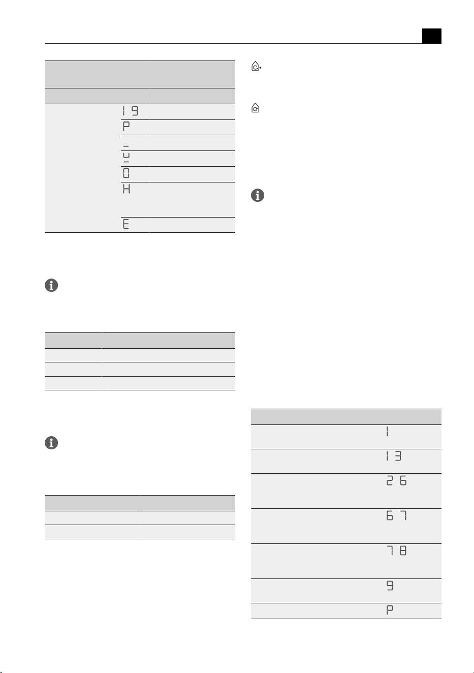
Menu item/Description/Selection Factory
setting
1 Volume of the acoustic signals (0–9) 4
2 Child lock (On/Off) Off
3 Show filter status
(reset filter service display)
4 Duration of the automatic after-run
function (10, 15, 20 min.)
20 min
5 Touch zone reaction speed
(1 slow, 2 medium, 3 fast)
2
6 LED test
7 Permanent pan size recognition Off
8 Software/hardware version
9 Safety shut-down
(1 long, 2 medium, 3 short)
2
A Super simple mode Off
0 Reset to factory settings
Tab.6.1
User menu overview
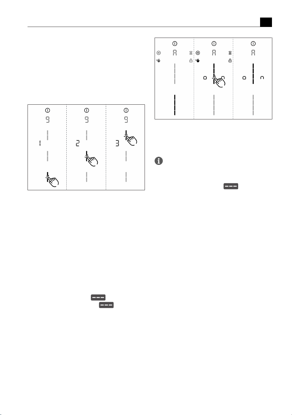
6.1
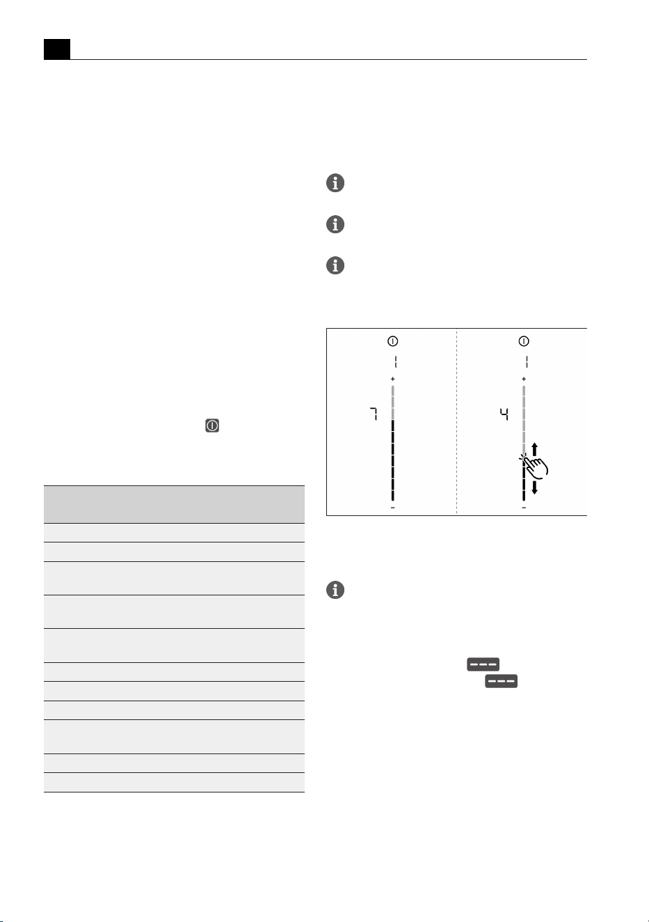
Menu item 1: volume of
the acoustic signals
Safety-relevant acoustic signals are always
emitted with the volume at 100%.
The acoustic signal for the power button cannot
be deactivated.
After accessing the menu item, the currently set
volume is displayed.
Setting the acoustic signal volume:
Fig.6.1
Menu item 1: volume of the acoustic signals
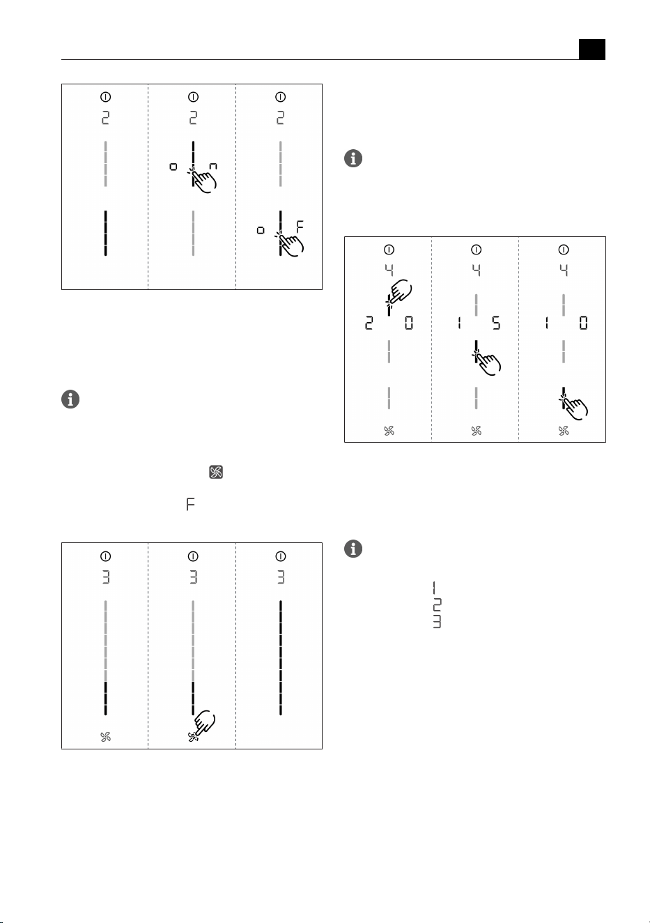
6.2
Menu item 2: Child lock
With menu item 2 the child lock can be
permanently switched on or off.
Permanently activating or deactivating the
child lock:
u
Tap the top slider segment to activate
u
Tap the bottom slider segment to deactivate
User menu
EN
bora.com 101
Fig.6.2
Menu item 2: Child lock
6.3
Menu item 3: Show filter
status and reset filter
service display
If menu item 3 is called up, the filter status will
be automatically shown (only in recirculation
mode).
Resetting the filter service display:
u
Long press on the fan button .
T
The filter status will be reset to 100%.
T
The filter service display will no longer be shown
when switching on.
Fig.6.3
Menu item 3: Reset filter status and the filter
service display
6.4
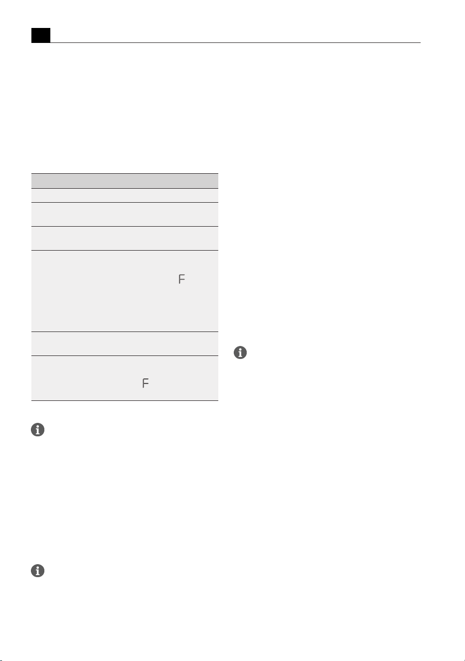
Menu item 4: Duration of
the automatic after-run
function
If menu item 4 is called up, the currently set
duration will be shown for 2 seconds.
There are three times to choose from:
20 minutes / 15 minutes / 10 minutes
Fig.6.4
Menu item 4: Selecting the duration of the
automatic after-run function
6.5
Menu item 5: Touch zone
reaction speed
If menu item 5 is called up, the currently set
reaction speed will be shown.
T
Reaction speed : slow
T
Reaction speed : medium
T
Reaction speed : fast
User menu
EN
102 bora.com
Selecting the reaction speed:
Fig.6.5
Menu item 5: Reaction speed
6.6
Menu item 6: LED test
Function inspection of all LEDs in the touch
zones.
Starting the LED test:
u
Tap the slider zone .
T
All indicators are displayed at 50 % brightness.
u
Tap any indicator you wish.
T
The selected indicator will be displayed at 100%
brightness for 1 second for testing purposes.
T
Any other indicators can be tested by touch.
Fig.6.6
Menu item 6: LED test
Ending the LED test:
u
Long press on the multi-function display.
The LED test will be automatically ended when
there has been no activity for 5 seconds.
6.7
Menu item 7: Permanent
pan size recognition
Switch permanent pan size recognition
permanently on or off.
Activate or deactivate permanent pan size
recognition:
u
Tap the top slider segment to activate.
u
Tap the bottom slider segment to deactivate.
Fig.6.7
Menu item 7: Permanent pan size recognition
6.8
Menu item 8: Show
software/hardware
version
The software/hardware version is shown via the
four 4 cooking zones indicators.
Fig.6.8
Menu item 8: Software/hardware version
6.9
Menu item 9: Safety
shut-down
The time span (level) until automatic safety
shut-down of the cooking zones can be selected
using menu item 9.
User menu
EN
bora.com 103
The current level is displayed:
T
Level 1: long time span until automatic safety shut-
down
T
Level 2: medium time span until automatic safety
shut-down (factory setting)
T
Level 3: short time span until automatic safety shut-
down
Selecting the level:
Fig.6.9
Menu item 9: Safety shut-down
6.10
Menu item A: Super
simple mode
The following additional functions and their indicator are
deactivated in the super simple mode:
T
Cooking zone timer
T
Short-time timer
T
Cleaning lock
T
Operating lock
T
Heat retention function
T
Pause function
Activating or deactivating super simple mode:
u
Tap the top slider segment to activate.
u
Tap the bottom slider segment to deactivate
Fig.6.10
Menu item A: Super simple mode
6.11
Menu item 0: Reset to
factory settings
Menu item 0 enables all settings in the user
menu to be reset to the factory settings.
Resetting to factory settings
u
Long press on the slider zone .
T
After resetting, the appliance is switched off.
Cleaning and maintenance
EN
104 bora.com
7 Cleaning and maintenance
u
Observe all safety and warning information
(see"2Safety").
u
When conducting cleaning and maintenance, ensure
that the cooktop and cooktop extractor are fully
switched off and cooled so as to prevent injury.
u
Adhere to the following cleaning and maintenance
cycles:
Component Cleaning cycles
Operating panel Immediately after every soiling
Cooktop Clean well immediately after soiling,
using conventional detergents
Cooktop
extractor
Weekly
Air inlet nozzle
and stainless
steel grease
filter
T
After cooking very greasy dishes,
but at least once a week
T
If filter service indicator appears
T
by hand or in the dishwasher
(at 65°C max.)
T
Clean the stainless steel surfaces
in the polishing direction only
Air guiding
housing
Every 6 months or when replacing the
activated charcoal filter
Activated
charcoal filter
(with recirculation
only)
Replace if odours have built up,
extraction power is dwindling or filter
service indicator
appears
Tab.7.1
Cleaning cycles
Regular cleaning and maintenance ensures long
service life of the product and optimal function.
7.1
Cleaning agents
u
Do not use any chemically aggressive cleaning
agents or agents containing acid or lye (e.g. oven
spray).
u
Make sure that the cleaning agent does not contain
any sand, soda, acids, lyes or chloride.
u
Never use a steam cleaner, abrasive sponges or
scouring pads.
Aggressive cleaning agents and abrasion
caused by the pot bases will damage the
surface and dark stains will occur.
7.2
Cooktop and extractor
care
u
Keep the appliance clean and immediately remove
any and all contamination.
u
Never use the cooktop as a work or storage surface.
u
Only use suitable cookware with the appliance.
u
Do not push or pull cookware over the cooktop.
u
Always lift pots and pans.
Any changes in colour or glossy spots do not mean that
the cooktop is damaged. They do not affect the
functionality of the cooktop or the stability of the glass
ceramic panel.
Changes in the colour of the cooktop are the result of
residues which have not been removed and have burnt
on.
Glossy spots are the result of wear by the pan base,
especially if aluminium-based cookware or unsuitable
cleaning agents are used. These are difficult to remove.
7.3
Cleaning the cooktop
To clean the cooktop, you need a special glass
ceramic scraper and suitable cleaning agents.
Scheduled cleaning
u
Remove all coarse dirt and food residues from the
cooktop using a glass ceramic scraper.
u
Apply the cleaning agent to the cold cooktop.
u
Spread the cleaning agent using kitchen roll or a
clean cloth.
u
Wipe the cooktop clean with a damp cloth.
u
Dry the cooktop with a clean cloth.
Heavy soiling
u
Remove heavy soiling and marks (limescale marks,
mother-of-pearl-like shiny marks) using cleaning
products while the cooktop is still warm.
u
Wipe off any food that boils over with a damp cloth.
u
Remove any remaining dirt with the glass ceramic
scraper.
Surface cleaning during operation
u
Always remove any seeds, crumbs or similar that fall
onto the cooktop during cooking immediately to
prevent the surface getting scratched.
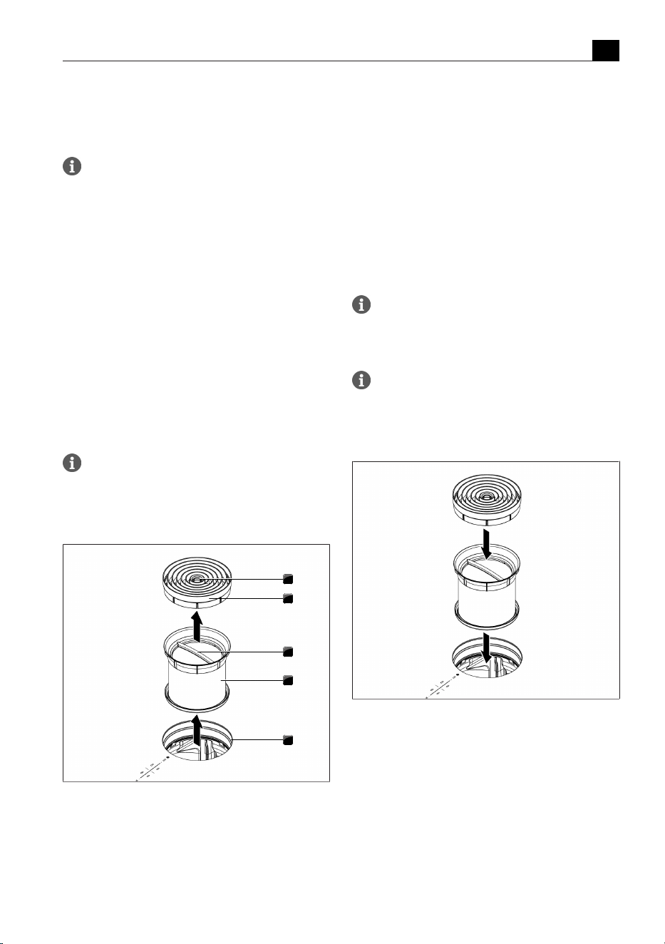
Cleaning and maintenance
EN
bora.com 105
u
Remove stubborn residues of plastic, aluminium foil,
sugar or sweet dishes from the hot cooking zone
immediately using a glass ceramic scraper to prevent
burning.
When the cooktop extractor is in use the air
inlet nozzle must be fitted so that no small or
light objects such as fabric or paper cleaning
cloths can be sucked in.
7.4
Cleaning the cooktop
extractor
u
Clean the surfaces of the extraction system using a
soft, damp cloth, detergent or a mild window
cleaning agent.
u
Soften dried on dirt using a damp cloth (do not
scrape it off!).
7.4.1
Cleaning the air inlet nozzle
and stainless steel grease
filter
The air inlet nozzle and stainless steel grease
filter absorb the greasy particles from cooking
vapours.
Removing the components
1
2
3
4
5
Fig.7.1
Removing the components
[1] Access opening
[2] Air inlet nozzle
[3] Handle
[4] Stainless steel grease filter
[5] Inlet opening
Manual cleaning
u
Use a cleaner and degreaser in one.
u
Rinse the components with hot water.
u
Clean the components with a soft brush.
u
Rinse the components well after cleaning.
Cleaning in the dishwasher
u
Remove coarse food residues from the components.
u
Place the components in the dishwasher.
u
No water should be able to gather in the
components.
u
Rinse the components with a rinsing program at a
maximum temperature of 65°C.
To prevent water from dripping into the
appliance, it is recommended to shake the
components well after cleaning and dry with a
towel if necessary.
If the stainless steel grease filter can no longer
be fully cleaned, it must be replaced (Warranty,
technical service, spare parts, accessories).
Fitting the components
Fig.7.2
Fitting the components
7.4.2
Removing liquids from the
appliance
Any liquids that flow into the appliance through the inlet
opening are caught by the stainless steel grease filter
(up to 150 ml) and in the air guiding housing.
Do the following:
u
Remove the air inlet nozzle and stainless steel grease
filter.
u
Empty the stainless steel grease filter.
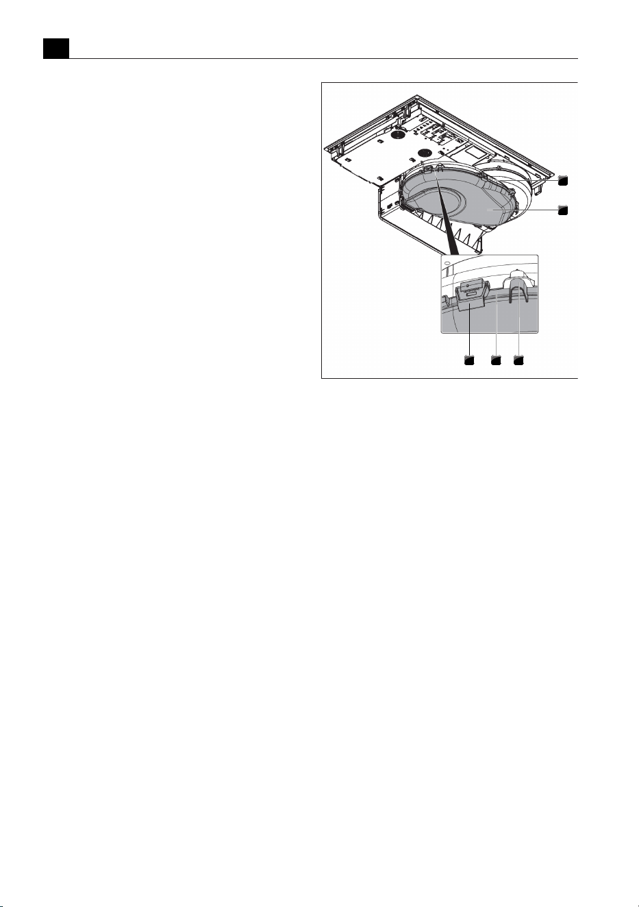
Cleaning and maintenance
EN
106 bora.com
u
Check whether any liquid has gathered in the base of
the air guiding housing.
u
If necessary, wipe the liquid up from the housing
base from above through the inlet opening using a
sponge or cloth.
u
Clean the air guiding housing.
u
To dry the activated charcoal filter and duct parts,
switch on the cooktop extractor at a minimum power
level of 5.
T
After 120 minutes the cooktop extractor will
automatically switch off and the automatic after-run
function will be started.
7.5
Cleaning the air guiding
housing
The air guiding housing can be found on the bottom of
the cooktop inside the floor unit.
Grease particles and limescale residues can settle on
the surface of the air guiding housing. For this reason,
regular cleaning is essential.
Opening the air guiding housing
u
Remove the air inlet nozzle and stainless steel grease
filter.
u
Remove the filter replacement cover (see figure).
u
Hold the housing base with one hand.
u
Release the 6 locks around the edge of the base.
u
Remove the housing base.
u
Clean the air guiding housing and the housing base
with a mild cleaning agent.
1
2
345
Fig.7.3
Air guiding housing
[1] Air guiding housing
[2] Housing base
[3] Spigot
[4] Sealing groove
[5] Lock
Closing the air guiding housing
u
Position the housing base under the air guiding
housing with the help of the 3 spigots.
u
Push the housing base upwards into the sealing
groove.
u
Close the 6 locks.
u
Check that the housing base is positioned correctly.
u
Insert the filter replacement cover (see figure).
u
Check that the filter replacement cover is positioned
correctly.
u
Insert the stainless steel grease filter and the air inlet
nozzle.
7.6
Replace the activated
charcoal filter
An activated charcoal filter will only be fitted with the
stainless steel grease filter if the cooktop extractor is
used in recirculation mode. The activated charcoal filter
absorbs cooking odours that arise during cooking.
Cleaning and maintenance
EN
bora.com 107
The activated charcoal filter must be replaced
when the fan indicator is shown
(filter service
display). You can obtain activated charcoal
filters from your specialist supplier or from the
BORA Shop via the website at
http://www.mybora.com.
Removing the activated charcoal filter
u
Remove the air inlet nozzle and stainless steel grease
filter.
u
Inside the inlet opening pull the filter replacement
cover out through the opening in the filter housing.
1 2
Fig.7.4
Removing the filter replacement cover
[1] Filter replacement cover
[2] Inlet opening
u
Take hold of the activated charcoal filter by the grip
strap and pull it out as far as possible through the
filter housing opening.
u
Take hold of the end of the activated charcoal filter
and pull upwards and towards the left until it is
completely out of the inlet opening.
1
2
Fig.7.5
Turning the activated charcoal filter from the
filter housing
[1] Grip strap
[2] Activated charcoal filter
Fig.7.6
Removing the activated charcoal filter through
the inlet opening
Inserting the activated charcoal filter
u
Remove the packaging from the activated charcoal
filter.
u
Position the activated charcoal filter correctly with
the help of the printed symbols (arrow left, grip strap
right).
u
Hold the activated charcoal filter at both ends.
u
Bend the activated charcoal filter into a cylindrical
shape so that both ends of the filter are opposite
each other.
1
2
Fig.7.7
Activated charcoal filter
[1] Activated charcoal filter
[2] Grip strap
u
Tilt the activated charcoal filter slightly and insert it
through the inlet opening.
Cleaning and maintenance
EN
108 bora.com
Fig.7.8
Inserting the activated charcoal filter through
the vent opening
u
Guide the left end of the filter into the opening in the
filter housing.
u
Push the activated charcoal filter into the filter
housing until it will go no further (to do this, you can
place one finger between the slats and gradually
push the filter into the housing).
T
The end position of the activated charcoal filter is
reached when the filter has been fully pushed inside
the filter housing.
Fig.7.9
Placing the activated charcoal filter in the end
position
u
Inside the inlet opening push the filter replacement
cover until it comes to a stop in the filter housing
opening.
u
Check that the filter replacement cover is positioned
correctly.
1 2
Fig.7.10
Inserting the filter replacement cover
[1] Filter replacement cover
[2] Inlet opening
u
Insert the stainless steel grease filter and the air inlet
nozzle.
u
Reset the filter service display (see"6.3Menu item 3:
Show filter status and reset filter service display").
Troubleshooting
EN
bora.com 109
8 Troubleshooting
You can often remedy faults and errors yourself. This saves time and money as you don’t need to call out
customer services.
u
Observe all safety and warning information (see"2Safety").
Operating situation Cause Remedy
Appliance cannot be switched on
Fuse/automatic circuit breaker defective
Replace the fuse;
Switch the automatic circuit breaker
back on
The fuse/automatic circuit breaker trips
several times
BORA Contact the Service Team.
The power supply is disconnected Have a specialist electrician inspect the
power supply
Odour formation when operating a new
appliance
This is normal with brand new
appliances
Odours stop forming after a few
operating hours
A cooking zone display shows
No or unsuitable cookware Use suitable, appropriately sized cook-
ware (see “Appliance description”)
The lock button lights up
Active child lock deactivate the child lock
Cooking zone/cooktop switches off
automatically
The maximum cooking zone operating
time has been exceeded
Put the cooking zone back into
operation
Power setting prematurely cancelled The overheating protection has tripped
see"5.7.6Overheating protection"
The cooktop cooling fan continues to run
when the cooktop has been switched off
The cooling fan runs until the cooktop
has cooled
Wait until the cooling fan switches off
automatically
Decreased extraction performance of
the cooktop extractor
Grease filter extremely dirty Clean or replace the grease filter
Activated charcoal filter extremely dirty
(recirculation only)
Replace the activated charcoal filter
Item in air guiding housing
(e.g. cleaning cloth)
Remove the object
or is displayed
Use of a phase-separating window
contact switch
Open the window
Fan defective or a duct connection has
become loose
BORA Contact the Service Team
is displayed
The overheating protection has tripped
see"5.7.6Overheating protection"
is displayed
Object on the operating panel Remove the object from the operating
panel
The operating panel is dirty Clean the operating panel
is shown (recirculation only)
End of activated charcoal filter service
life reached
Insert a new activated charcoal filter
(see"7.6Replace the activated char-
coal filter").
Tab.8.1
Troubleshooting
Faults and errors not covered:
u
Switch off the appliance.
u
Contact the BORA Service Team Team (see see"11Warranty, technical service, spare parts, accessories") and
enter the error number displayed and the appliance type.
Installation
EN
110 bora.com
9 Installation
u
Observe all safety and warning information
(see"2Safety").
9.1
General installation
instructions
The power supply cable must be provided by the
customer.
The appliance must not be installed above
cooling devices, dishwashers, stoves, ovens,
washing machines or dryers.
The contact surfaces of the worktops and wall
sealing strips must be made of a heat-resistant
material (up to approx. 100°C).
Worktop cut-outs must be moisture-sealed
using suitable means and, where necessary,
fitted with a thermal insulator.
The integrated cooktop extractor must not be
used with other cooktops.
General installation instructions for cooktops
u
Make sure that the area below the cooktop has a
sufficient air supply.
To maintain the level of performance, sufficient
ventilation below cooktops must be ensured.
The performance is affected or the cooktops
overheat if the warm air beneath the cooktops
cannot escape.
In the event of overheating, the cooktop power is
reduced or the appliance is switched off completely.
If cable protection (false floor) is planned
beneath the appliance, this must be fitted so it
does not obstruct ventilation.
9.1.1
Simultaneous operation of
the cooktop extractor in the
exhaust air mode with a
fireplace dependent upon the
air supply in the room
Fireplaces that depend on the air in the room (e.g. gas,
oil, wood or coal-fired heaters, continuous-flow water
heaters, instantaneous water heaters) draw in air from
the room in which they are installed and release the
exhaust fumes into the outside air via an exhaust
system (e.g. chimney).
If the cooktop extractor is used in exhaust air mode, it
draws in air from the room in which it is installed as well
as from neighbouring rooms. Without sufficient air,
there will be a drop in air pressure. Toxic gases could be
drawn out of the chimney or extraction ducting and
back into the room.
Fig.9.1
Exhaust air installation – not permitted
Fig.9.2
Exhaust air installation – correct
u
If simultaneously operating both the cooktop with a
fireplace and the cooktop extractor in the room they
are installed, ensure that...
T
...the maximum low pressure is 4Pa;
T
...a safety device (e.g. window contact switch, low
pressure warning device) is used to ensure that a
sufficient supply of fresh air is guaranteed;
T
...the exhaust air is not channelled into a chimney
that is used for exhaust gases of appliances operated
with gas or other combustibles;
T
...the installation is checked and approved by an
authorised certified engineer (e.g. heating engineer).
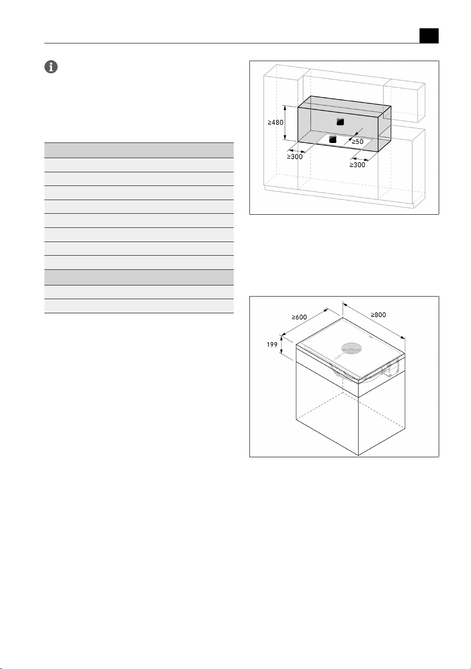
Installation
EN
bora.com 111
If the cooktop extractor is used exclusively in
recirculation mode, simultaneous operation with
a fireplace dependent on the air in the room is
possible without any additional safety measures.
9.2
Scope of delivery
Scope of delivery
Quantity
Cooktop with integrated cooktop extractor 1
Air inlet nozzle 1
Stainless steel grease filter 1
Operating and installation instructions 1
Installation clamps 4
Sealing tape 1
Height adjustment plate set 1
Bag containing various small parts for assembly 1
Additional scope of delivery PURMU
Activated charcoal filter 1
Template for back panel cut-out 1
Tab.9.1
Scope of delivery
Checking the scope of delivery
u
Make sure the delivery is complete and check it for
damage.
u
Immediately notify the BORA Service TeamTeam if
parts are missing or damaged.
u
Do not under any circumstances install parts which
are damaged.
u
Dispose of transport packaging in the proper manner
(see"10Decommissioning, disassembly and disposal").
9.3
Tools and aids
The following tool, among others, is required to
correctly install the appliance:
T
Jigsaw or handsaw
T
size 20 Torx screwdriver key
T
black, heat-resistant silicone sealant
T
Template for cut-out on back panel (recirculation
only, included in scope of delivery)
9.4
Assembly instructions
9.4.1
Installation clearances
u
Observe the required clearance around the worktop
cut-out.
1
2
Fig.9.3
Required clearance
[1] Required clearance
[2] Worktop cut-out
9.4.2
Minimum unit dimensions
Fig.9.4
Minimum unit dimensions for M Pure
9.4.3
Information on kitchen units
T
Cross bars on the kitchen unit in the area of the
worktop cut-out may need to be removed.
T
In the case of thin worktops, there must be a
sufficiently rigid support plate on the unit.
T
The drawers and/or shelves in the floor unit must be
removable.
T
The drawers of the floor unit must be shortened
depending on the installation situation.
If false floor (cable protection) is planned, the following
must be taken into account:
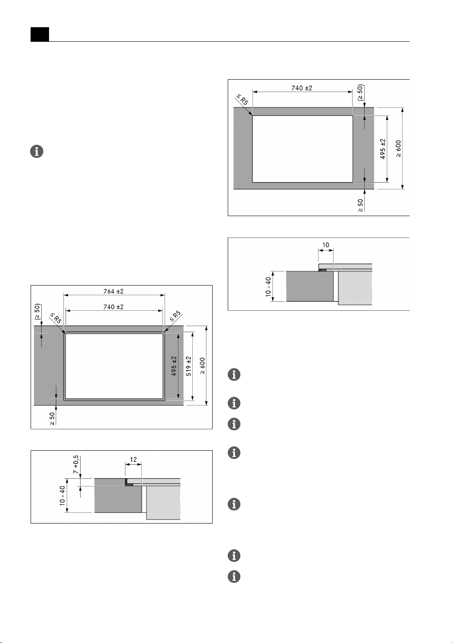
Installation
EN
112 bora.com
T
It must be fitted in such a way that it can be removed
from below for maintenance work.
T
To ensure sufficient cooktop ventilation, a minimum
distance of 15mm to the bottom edge of the
cooktop is to be observed.
9.5
Worktop cut-out
The minimum measurement of 50 mm from the
front edge of the worktop to the worktop
cut-out is a recommendation from BORA.
u
Create the worktop cut-out taking into account the
specified cut-out dimensions.
u
Make sure that the cut surfaces of the worktops are
properly sealed.
u
Comply with the instructions of the worktop manufacturer.
9.5.1
Cut-out dimensions
Flush installation
Fig.9.5
Cut-out dimensions for flush installation
Fig.9.6
Rebate dimensions for flush installation
Surface mounting
Fig.9.7
Cut-out dimensions for surface mounting
Fig.9.8
Overlay dimensions for surface mounting
9.6
Installing the appliance
in exhaust air mode
National and regional laws and regulations must be
observed with regard to the exhaust duct design.
A sufficient air supply must be ensured.
The exhaust air must be directed to the outside
by appropriate exhaust air ducts.
The minimum cross section of the exhaust air
duct must be 176 mm
2
which equates to a
round pipe with a diameter of 150mm or the
BORA Ecotube duct system.
As a general rule, with the built-in fan, a length
of duct of up to 6 metres with six 90° bends,
8 metres with four 90° bends or 10 metres with
two 90° bends can be installed.
Not compatible with BORA Universal fans.
Planning instructions for the installation of the
exhaust air ducts are provided in the BORA
planning guide.
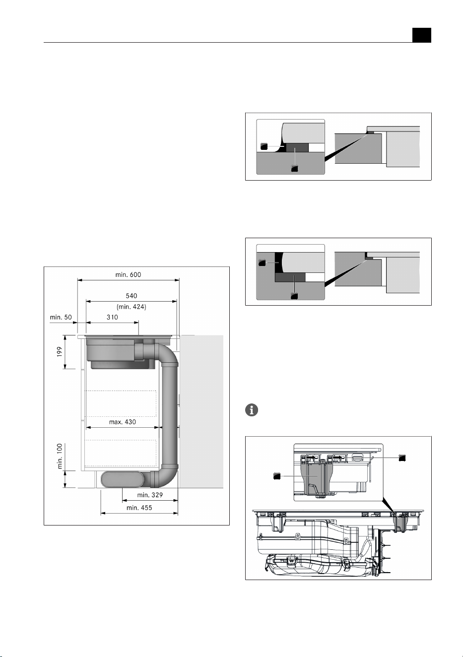
Installation
EN
bora.com 113
9.6.1
Preparing kitchen units for
the exhaust air model
T
The back panel of the floor unit must be adapted for
the exhaust air duct.
T
A minimum clearance of 120 mm between the back
panel of the unit and an adjacent kitchen unit or
room wall must be kept for the air duct.
T
No false floor is necessary below the cooktop.
Adjusting the back panel of the unit
u
Before installation, check the suitability of the floor unit
with regard to the necessary installation dimensions for
the appliance and the planned duct system.
u
If necessary, adjust the position of the back panel
according to the required installation dimensions.
9.6.2
Installation dimensions
Fig.9.9
Installation dimensions for exhaust air,
worktop depth 600 mm
9.6.3
Preparing the appliance
Attaching the sealing tape
u
In the case of surface mounting, attach the enclosed
sealing tape around the outer edges of the underside
of the cooktop. Do not leave any gaps.
u
In the case of flush installation, attach the sealing
tape to the contact surfaces in the worktop cut-out,
even if you are sealing the cooktop with a silicone
sealing compound or similar.
1
2
Fig.9.10
Sealing tape in the case of surface mounting
[1] Black, heat-resistant silicone sealant
[2] Sealing tape
1
2
Fig.9.11
Sealing tape in the case of flush installation
[1] Black, heat-resistant silicone sealant
[2] Sealing tape
Fitting the installation clamps
u
Push 2 installation clamps onto each side of the cooktop
until they come to a stop in the retaining brackets provided.
2 installation clamps must be fitted to each side
of the cooktop.
1
2
Fig.9.12
Fitting the installation clamps
[1] Retaining brackets
[2] Installation clamps
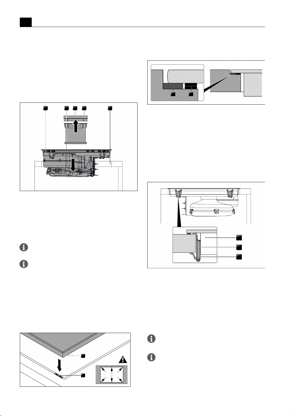
Installation
EN
114 bora.com
9.6.4
Inserting the cooktop
u
Before inserting the cooktop, remove the air inlet
nozzle and the stainless steel grease filter.
u
Use the inlet opening as a handle during insertion.
u
Keep the cooktop straight as you lift it into the
worktop cut-out.
u
Insert the cooktop into the centre of the worktop cut-out.
u
Precisely align the cooktop.
1 2 3 4 5
Fig.9.13
Positioning the cooktop in the centre
[1] Cooktop
[2] Inlet opening
[3] Air inlet nozzle
[4] Stainless steel grease filter
[5] Worktop cut-out
Make sure that the cooktop sealing tape is flat against
the worktop in the case of surface mounting.
Make sure that the cooktop sealing tape is well sealed
all the way round in the case of flush installation.
Height adjustment plates for flush installation
(optional)
T
The height adjustment plates are self-adhesive to
prevent slipping during installation.
u
If applicable, insert the height adjustment plates.
u
Place the height adjustment plates next to the
sealing tape.
1
2
Fig.9.14
Positioning the height adjustment plates
[1] Cooktop
[2] Height adjustment plate
1 2
Fig.9.15
Height adjustment plates
[1] Sealing tape
[2] Height adjustment plate
9.6.5
Securing the cooktop
u
Secure the cooktop to the worktop with the fixing
bracket on the installation clamp.
u
Tightening torque: max. 2.2Nm.
1
2
3
Fig.9.16
Securing the cooktop in the middle
[1] Cooktop
[2] Mounting bracket
[3] Fixing bracket
9.6.6
Connecting the appliance to
the duct system
The duct system must be fitted to the appliance
free of load and with the power supply switched off.
When attaching the seals, ensure that an
airtight seal is created with the connecting duct
piece when the seals are compressed.
u
Use only BORA Ecotube duct parts.
u
Do not use flexible or fabric hoses.
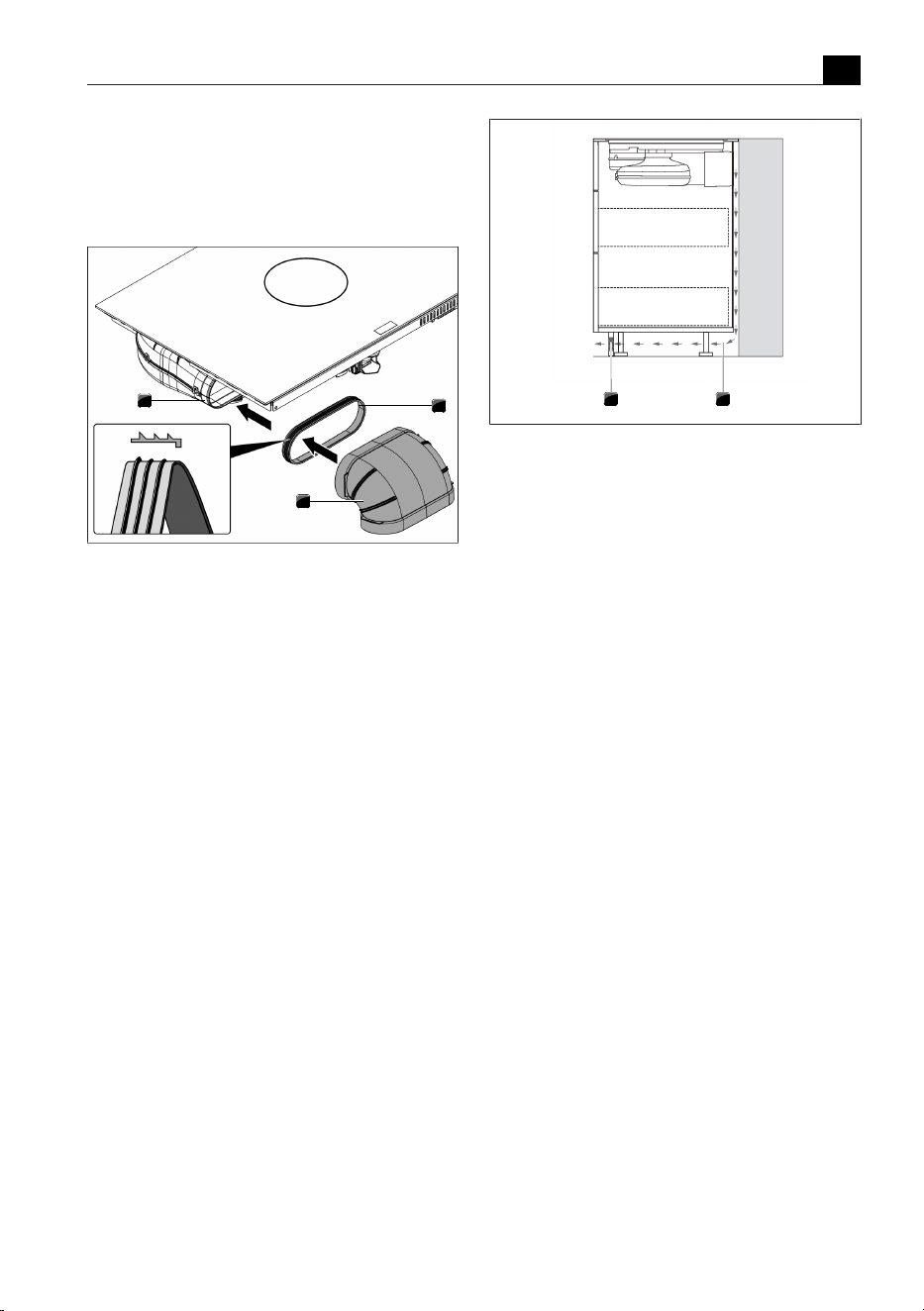
Installation
EN
bora.com 115
u
Pull the seal onto the exhaust opening on the
appliance. The seal will need to be stretched slightly.
u
Push the duct part to be connected with the coupling
onto the exhaust opening with the seal.
u
Ensure that the seal is not displaced.
1
2
3
Fig.9.17
Connecting the duct system
[1] Seal
[2] Duct part
[3] Exhaust opening
9.7
Installing the appliance
in recirculation mode
9.7.1
Recirculation of air from the
kitchen unit
In the case of recirculation systems, a return flow
aperture must be provided in the kitchen unit to guide
the clean recirculated air out of the unit and back into
the room. The return flow aperture can be created
above a shortened plinth. A slatted plinth with at least
the minimum opening cross-section can also be used.
u
Decrease the height of the plinth panel or create
corresponding openings in the plinth.
u
The cross-section of the return flow aperture must be
≥ 500cm² for each cooktop extractor.
1
2
Fig.9.18
Return flow aperture in the plinth area
[1] Return flow aperture in the plinth (total cross-section
of the aperture ≥500 cm²)
[2] Return flow of recirculated air
9.7.2
Installation variants (A and B)
for recirculation appliances
There are 2 installation variants for recirculation appliances:
A: floor unit with continuous back panel
The recirculated air is guided through the connection
with the back wall of the air purification box directly
behind the back panel of the unit. The recirculated air
goes back in to the room through the return flow
aperture.
For installation purposes, this means that:
T
No false floor is necessary below the cooktop.
T
There must be a cut-out in the back panel.
B: floor unit with false floor under the cooktop
The recirculated air is blown into the free space between
the worktop and the false floor (the air purification box
does not connect with the back panel). The recirculated
air goes behind the back panel of the unit and through
the return flow aperture back into the room.
For installation purposes, this means that:
T
a false floor is necessary below the cooktop.
T
There does not need to be a cut-out in the back
panel of the unit.
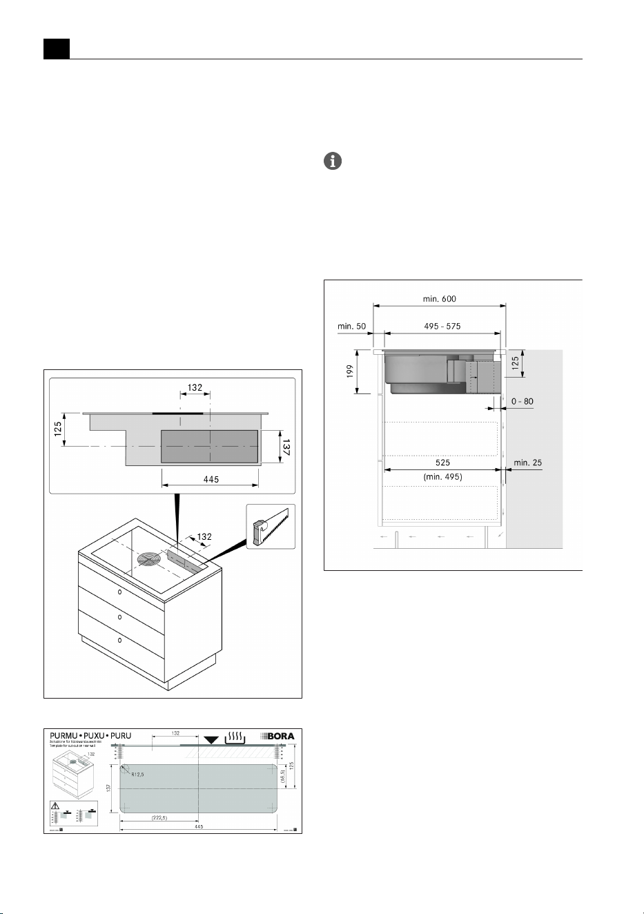
Installation
EN
116 bora.com
9.7.3
Preparing the kitchen unit for
installation variant A
T
The floor unit must have a continuous back panel so
that the recirculated air is not directed into the front
furniture body compartment.
T
There must be a cut-out in the back panel.
T
A minimum clearance of 25 mm between the back
panel of the unit and an adjacent kitchen unit or
room wall must be kept for the return flow aperture.
T
No false floor is necessary below the cooktop.
Adjusting the back panel of the unit
u
Adapt the back panel according to the required
installation dimensions.
u
If necessary, move the back panel.
u
If necessary, extend the height of the back panel so
that the unit is closed to the front.
Fig.9.19
Back panel cut-out
Fig.9.20
Template for back panel cut-out
u
Position the template on the back panel of the unit
with the help of the markings and instructions.
u
Mark out the back panel cut-out.
u
Cut out the back panel cut-out with a saw.
Flush and surface mounting options must be
taken into account when positioning the
template. 125mm from top edge of the
cooktop to centre of cut-out.
9.7.4
Installation dimensions for
installation variant A
Fig.9.21
Installation dimensions in the case of
recirculated air, installation variant A
9.7.5
Preparing the kitchen unit for
installation variant B
T
A false floor must be provided for under the cooktop.
T
The back panel of the unit must be flush with the
false floor so that the recirculating air is not directed
into the front of the unit.
T
A minimum clearance of 25 mm between the back
panel of the unit and an adjacent kitchen unit or
room wall must be kept for the return flow aperture.
Adjusting the back panel of the unit
u
Adapt the back panel according to the required
installation dimensions.
u
If necessary, move the back panel.
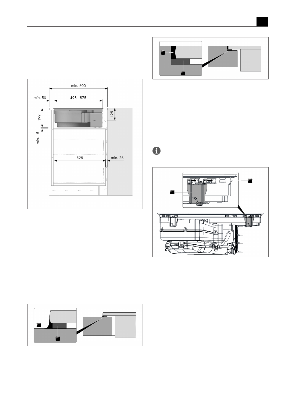
Installation
EN
bora.com 117
u
Adjust the height of the back panel to the false floor
so that they are flush with one another.
9.7.6
Installation dimensions for
installation variant B
Fig.9.22
Installation dimensions for recirculation
installation variant B, depth of worktop 600 mm
9.7.7
Preparing the appliance
Attaching the sealing tape
u
In the case of surface mounting, attach the enclosed
sealing tape around the outer edges of the underside
of the cooktop. Do not leave any gaps.
u
In the case of flush installation, attach the sealing
tape to the contact surfaces in the worktop cut-out,
even if you are sealing the cooktop with a silicone
sealing compound or similar.
1
2
Fig.9.23
Sealing tape in the case of surface mounting
[1] Black, heat-resistant silicone sealant
[2] Sealing tape
1
2
Fig.9.24
Sealing tape in the case of flush installation
[1] Black, heat-resistant silicone sealant
[2] Sealing tape
Fitting the installation clamps
u
Push 2 installation clamps onto each side of the
cooktop until they come to a stop in the retaining
brackets provided.
2 installation clamps must be fitted to each side
of the cooktop.
1
2
Fig.9.25
Fitting the installation clamps
[1] Retaining brackets
[2] Installation clamps
9.7.8
Extending the telescopic pull-
out of the air purification box
If the depth of the worktop exceeds 675 mm in installation
variant A, the telescopic pull-out of the air purification box
must be extended using the accessory PULBTA.
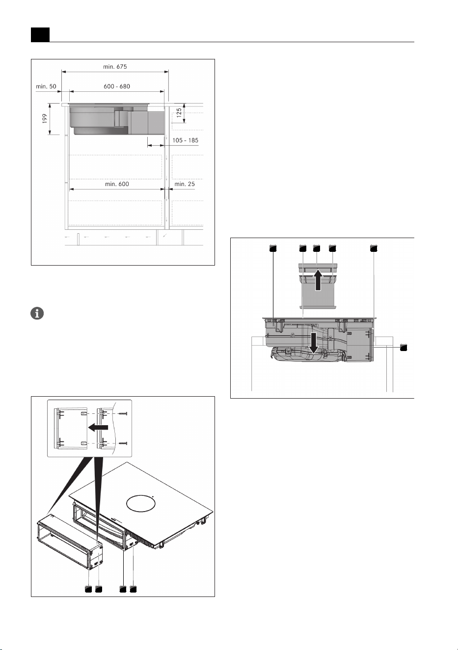
Installation
EN
118 bora.com
Fig.9.26
Installation dimensions for recirculation
installation variant A, depth of worktop 675 mm
and over
The telescopic pull-out is used to connect the duct
to the back panel of the kitchen unit. This can be
used to flexibly bridge the gap between the
cooktop and the back panel of the kitchen unit
(max. 80 mm). If necessary, the telescopic pull-
out can be extended by a further 105 mm using
the extension PULBTA (available as an accessory).
1234
Fig.9.27
Extending the telescopic pull-out
[1] Air purification box with telescopic pull-out
[2] Telescopic pull-out adhesive tape
[3] Telescopic pull-out extension PULBTA
[4]
Adhesive tape for telescopic pull-out extension PULBTA
u
Remove the protective film from the adhesive tape
on the front of the telescopic pull-out.
u
Attach the extension PULBTA (available as an
accessory including screws for attachment) to the
telescopic pull-out.
u
Remove the protective film from the adhesive tape
on the front of the extension PULBTA.
9.7.9
Inserting the cooktop –
recirculation
1 2 3 4 5
6
Fig.9.28
Positioning the cooktop in the centre
[1] Cooktop
[2] Inlet opening
[3] Air inlet nozzle
[4] Stainless steel grease filter
[5] Worktop cut-out
[6] Adhesive tape
u
Before inserting the cooktop, remove the air inlet
nozzle and the stainless steel grease filter.
u
Remove the protective film from the adhesive tape
on the front of the telescopic pull-out.
u
Use the inlet opening as a handle during insertion.
u
Keep the cooktop straight as you lift it into the
worktop cut-out.
u
Insert the cooktop into the centre of the worktop
cut-out.
u
Precisely align the cooktop.
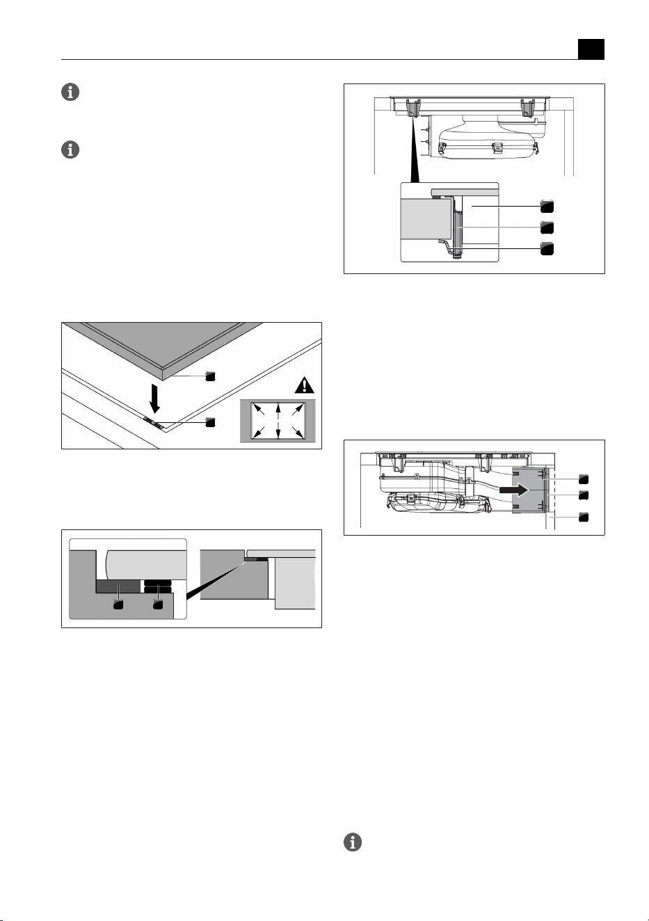
Installation
EN
bora.com 119
Make sure that the cooktop sealing tape is flat
against the worktop in the case of surface
mounting.
Make sure that the cooktop sealing tape is well
sealed all the way round in the case of flush
installation.
Height adjustment plates for flush installation
(optional)
T
The height adjustment plates are self-adhesive to
prevent slipping during installation.
u
If applicable, insert the height adjustment plates.
u
Place the height adjustment plates next to the
sealing tape.
1
2
Fig.9.29
Positioning the height adjustment plates
[1] Cooktop
[2] Height adjustment plate
1 2
Fig.9.30
Height adjustment plates
[1] Sealing tape
[2] Height adjustment plate
9.7.10
Securing the cooktop
u
Secure the cooktop to the worktop with the fixing
bracket on the installation clamp.
u
Tightening torque: max. 2.2Nm.
1
2
3
Fig.9.31
Securing the cooktop in the middle
[1] Cooktop
[2] Mounting bracket
[3] Fixing bracket
9.7.11
Making a connection with the
back panel in installation
variant A
1
2
3
Fig.9.32
Connection with the back panel
[1] Telescopic pull-out
[2] Adhesive tape
[3] Back panel of unit
u
Push the telescopic pull-out until it is tight up against
the back panel of the unit.
T
With the telescopic pull-out the distance to the back
panel of the unit can be flexibly bridged.
u
Check that the telescopic pull-out fits accurately, is
flush with the cut-out on the back panel of the unit
and closes it off.
u
Secure the telescopic pull-out to the back panel of
the unit using the adhesive tape.
9.7.12
Inserting the activated
charcoal filter
See chapter Cleaning and maintenance, “7.6
Replacing the activated charcoal filter”
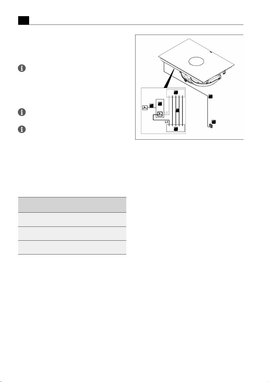
Installation
EN
120 bora.com
9.8
Connecting the power
supply
u
Observe all safety and warning information (see"2Safety").
Assembly, installation and commissioning must
always occur in line with national laws,
regulations and standards. The work must be
performed by qualified specialists who know
and comply with the additional regulations of
the local energy supply companies.
Connections via plug-in contacts (Schuko plugs)
are not permitted.
1-phase connection. The appliance complies
with the requirements of IEC 61000-3-12.
u
Switch off the main switch/automatic circuit breaker
before connecting the cooktop.
u
Secure the main switch/automatic circuit breaker
against being switched back on without permission.
u
Make sure the power to the appliance is disconnected.
u
Connect the cooktop exclusively via a fixed
connection to an H 05 VV-F power supply cable with
corresponding minimum cross-section.
Connection Fuse protection Minimum
cross-section
Three-phase
connection
3 x 16 A 2.5mm²
Two-phase
connection
2 x 16 A 2.5mm²
One-phase
connection
1 x 32 A 4mm²
Tab.9.2
Fuse protection and minimum cross-section
1
2
3
4
5
1
2
S1
Fig.9.33
Connection diagram with external switch contact
[1] Cooktop and cooktop extractor power supply cable
[2] Power supply
[3] Cooktop and cooktop extractor power supply
[4] Switch relay
[5] Switch connection S1 and switch relay
[S1] External switch contact
u
Connect the mains supply cable to the power supply
of the appliance in accordance with the relevant
connection diagram (see figures or underside of
appliance).
u
For a single-phase or two-phase connection, connect
the relevant contacts using the bridge provided (in
scope of delivery).
u
Secure the connection cable with the strain relief
clamp (in scope of delivery).
u
Close the power supply housing with the power
supply cover (in scope of delivery).
u
Lay the connection cable along the mounting eyes
with the help of the cable ties (in scope of delivery).
u
Ensure that the cable is not trapped or damaged and
is not able to come into contact with any hot areas
on the cooktop.
u
Check that installation has been carried out
correctly.
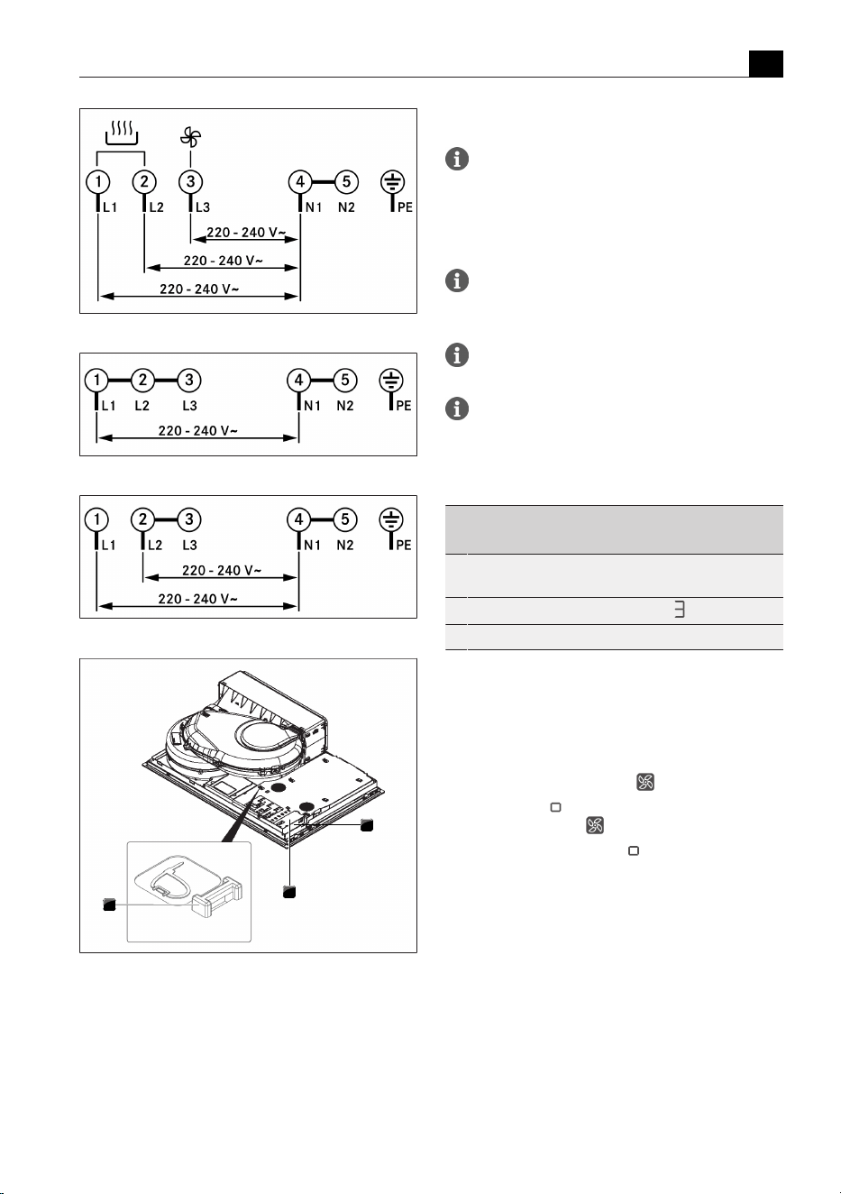
Installation
EN
bora.com 121
Fig.9.34
Connection diagram for 3-phase connection
Fig.9.35
Connection diagram for 1-phase connection
Fig.9.36
Connection diagram for 2-phase connection
1
2
3
Fig.9.37
Electrical connections of the cooktop
[1] Power supply
[2] Power supply cover
[3] Mounting eyes
9.9
Initial operation
During initial operation some basic settings
(basic configuration) must be applied using the
dealer and service menu.
9.9.1
Dealer and service menu
The dealer and service menu can be called up
up to 2 minutes after the appliance has been
connected to the power supply.
The system adopts and saves the settings made
when you exit the corresponding menu item.
Below you will find explanations on how to use
the menu and a description of the most
important menu items.
Dealer and service menu overview
Menu item/Description/
Selection area
Factory setting
B Extraction system
(exhaust air/recirculation system)
Recirculation
C Power management
D Demo mode Off
Tab.9.3
Menu overview
Calling up the dealer and service menu
u
Connect the appliance to the power supply.
T
The standard display appears and the fan symbol
pulses for 2 minutes.
u
Long press on the fan button .
T
4 input points are shown.
u
Keep the fan button pressed and at the same
time press the input points
in the specified order.
T
Menu item B is displayed.
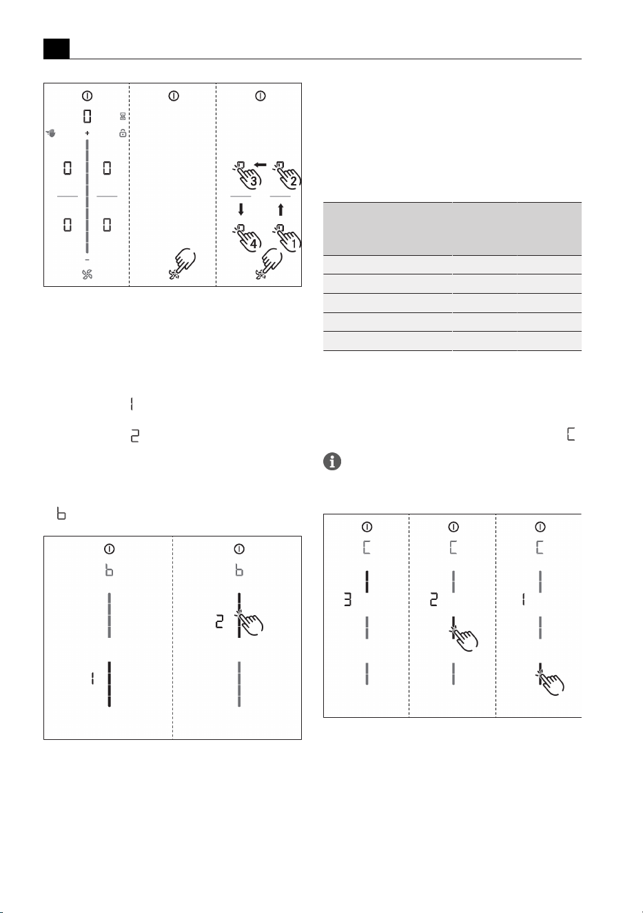
Installation
EN
122 bora.com
Fig.9.38
Calling up the dealer and service menu
9.9.2
Menu item B: Extraction
system configuration
The extraction system must be configured.
There are two operating modes to choose from:
T
Operating mode : recirculation system (factory
setting)
T
Operating mode : exhaust air system
u
Select the corresponding operating mode (tap the
corresponding segment on the slider ).
u
Confirm and save the setting by moving to the next
menu item (tap the multi-function display/indicator
).
Fig.9.39
Display Menu item B: Configuring the
extraction system
9.9.3
Menu item C: Power
management
The total appliance power can be reduced if the
required electrical power cannot be provided at the
installation site.
There are three operating modes to choose from:
Power
management
Connection
Maximum
power
consumption
Fuse
protection
C3 three-phase 7600 W 3 x 16 A
C3 two-phase 7600 W 2 x 16A
C3 single-phase 7600 W 1 x 32 A
C2 single-phase 4400 W 1 x 20 A
C1 single-phase 3600 W 1 x 16A
Tab.9.4
Power management
u
Select the corresponding operating mode (tap the
corresponding segment on the slider ).
u
Confirm and save the setting by moving to the next
menu item (tap the multi-function display/indicator
).
The cooking zone power restrictions
automatically implemented by the appliance are
determined according to the total power set.
Fig.9.40
Display menu item C: Power management
9.9.4
Menu item D: Demo mode
The appliance can be set to demo mode, which includes
all operating functions, but the heating function of the
cooktops is deactivated.
u
Tap the top slider segment.
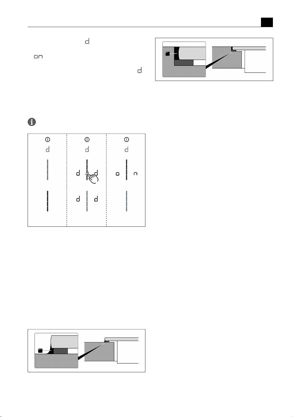
Installation
EN
bora.com 123
T
The demo mode symbol is displayed on all
cooking zones for one second.
T
is displayed.
u
Confirm and save the setting by moving to the next
menu item (tap the multi-function display/indicator
).
Closing the dealer and service menu
When you have been through all of the basic
configuration menu items:
u
long press on the multi-function display.
u
The standard display appears.
Pan size recognition is deactivated in demo mode.
Fig.9.41
Display Menu item D: Demo mode
9.9.5
Function test
u
Carry out a thorough function test on all appliances.
u
In the event of error messages, see the
“Troubleshooting” chapter.
9.10
Sealing the appliance
u
Once all of the installation work is complete, seal the
appliance with black, heat-resistant silicone sealant.
u
Make sure that no silicone sealant gets under the
cooktop.
1
Fig.9.42
Silicone sealant for surface mounting
[1] Black, heat-resistant silicone sealant
1
Fig.9.43
Silicone sealant for flush installation
[1] Black, heat-resistant silicone sealant
9.11
Handover to user
Once installation is complete:
u
Explain the main functions to the user.
u
Explain all safety-related aspects of operation and
handling to the user.
u
Provide the user with the accessories and operating
and installation instructions, which are to be kept in
a safe place.
Decommissioning, disassembly and disposal
EN
124 bora.com
10 Decommissioning, disassembly and
disposal
u
Observe all safety and warning information
(see"2Safety").
u
Follow the enclosed manufacturer’s information.
10.1
Decommissioning
Decommissioning refers to ultimate decommissioning
and disassembly. Following decommissioning, the
appliance can either be installed in another unit, sold on
privately or disposed of.
The electricity connection may only be
disconnected and cut off by certified
specialists.
u
Switch the appliance off before decommissioning
(see operating instructions)
u
Disconnect the appliance from the power supply.
10.2
Disassembly
To be removed, the appliance must be accessible for
disassembly and disconnected from the power supply.
u
Remove the silicone seals.
u
Lift the appliance up and out through the top of the
worktop.
u
Remove any other accessories.
u
Dispose of the old appliance and any soiled
accessories as described under “Environmentally-
friendly disposal”.
10.3
Environmentally-friendly
disposal
10.3.1
Disposal of transport
packaging
The packaging protects the appliance from
damage during transport. The packaging
materials have been selected taking into
account the environment and their disposal and
are therefore recyclable.
Recycling the packaging saves raw materials and
reduces waste. Your specialist retailer will take the
packaging back.
u
Give the packaging to your specialist retailer
or
u
dispose of the packaging correctly observing regional
regulations.
10.3.2
Disposal of accessories
Dispose of unnecessary or used accessories (activated
charcoal filters, etc.) accordingly taking into account
the regional regulations.
10.3.3
Disposal of the old appliance
Electrical appliances with this mark
must not be disposed of in the house-
hold waste at the end of their service
life. They must be disposed of at a col-
lection point for the recycling of elec-
trical or electronic appliances. Inform-
ation on this can be obtained from the
city or local councils.
Waste electrical and electronic appliances often still
contain valuable materials. However, they also contain
harmful substances that were necessary to make them
work and ensure their safety. If placed in the household
waste or handled incorrectly, they may harm human
health and damage the environment.
u
Never dispose of your old appliance in the household
waste.
u
Take the appliance to a regional collection point for
the return and further processing of electrical and
electronic components and other materials.

Warranty, technical service, spare parts, accessories
EN
bora.com 125
11 Warranty, technical service, spare parts,
accessories
u
Observe all safety and warning information
(see"2Safety").
11.1
BORA manufacturer’s
warranty
BORA provides its end customers with a 2-year
manufacturer’s warranty for its products. The end
customer is entitled to this warranty in addition to the
statutory claims for defects against the sellers of our
products.
The manufacturer’s warranty applies to the
BORAproducts listed here, which are sold by authorised
BORA retailers or by BORA trained salespersons and are
installed within the European Union (overseas territories
excluded), Switzerland, Liechtenstein, Ukraine, Russia,
Norway, Serbia, Israel, UK, Iceland, India, Australia and
New Zealand, with the exception of BORA products
labelled as universal or accessories:
T
Cooktops
T
Cooktop extractor systems
T
Fans
The manufacturer’s warranty starts as soon as the
BORA product is handed over to the end customer and
is valid for 2 years. Registering on www.mybora.com
enables the manufacturer’s warranty to be extended to
3 years.
The manufacturer’s warranty requires expert installation
(in accordance with the valid BORA planning guide and
operating instructions at the time of installation) of the
BORA products by an authorised BORA retailer. During
use, the end customer is to adhere to the specifications
and instructions in the operating manual.
When filing a warranty claim, BORA must be directly
notified of the fault and the receipt must be presented.
Alternatively, proof of purchase can be provided by
registering on www.mybora.com.
BORA guarantees that all BORA products are free from
material and production defects. The defect must exist
prior to delivery of the product to the end customer.
Filing a warranty claim does not interrupt the warranty
period, nor shall the period start anew.
BORA will correct defects in BORA products at its own
discretion by repairing or replacing the product. All
costs for the correction of defects under the
manufacturer’s warranty shall be assumed by BORA.
Expressly not covered by the BORA manufacturer’s
warranty are:
T
BORA products that were not sold by authorised
BORA dealers or salespersons trained by BORA
T
Damage caused by non-adherence to the operating
instructions (including product care and cleaning).
This represents improper use.
T
Damage caused by normal use, e.g. traces of usage
on the cooktop
T
Damage caused by external influences (such as
transport damage, ingress of condensation, damage
caused by the elements such as a lightning strike)
T
Damage caused by repairs or repair attempts that
were not carried out by BORA or by persons
authorised by BORA .
T
Damage to the glass ceramic
T
Injury caused by electrical voltage fluctuations
T
Secondary damage or claims for damages beyond
the defect
T
Damage to plastic parts
Legal claims, particularly statutory claims for defects or
product liability are not limited by the warranty and can
be asserted free of charge.
If a defect is not covered by the manufacturer’s
warranty, a claim may be made against the BORA
Technical Service.
. BORA shall not assume the resulting costs.
The laws of the Federal Republic of Germany apply to
these warranty conditions.
You can contact us at:
BORA Vertriebs GmbH & Co KG, Innstraße 1, 6342
Niederndorf, Austria
T
Telephone: +800 7890 0987
Monday to Thursday from 8 a.m. to 6 p.m. and Friday
from 8 a.m. to 5 p.m.
T
Email: [email protected]
11.1.1
Warranty extension
You can extend the warranty by registering at
www.bora.com/registration .
11.2
Service
BORA Service:
see reverse side of operating and assembly instructions
Warranty, technical service, spare parts, accessories
EN
126 bora.com
u
In the case of faults you cannot fix yourself, contact
your BORA specialised retailer or the BORA Service
Teamappears in the cooktop extractor control knob
display.
The BORA Service Team Team will require the type
designation and serial number of your appliance
(FD number).
This information is provided on the nameplate on the
warranty form as well as on the bottom of the
appliance.
11.3
Spare parts
u
Only use original spare parts for repairs.
u
Repairs may only be carried out by the BORA Service
Team.
Spare parts can be obtained from your BORA
dealer, the BORA online service website at
www.bora.com/service or by calling the service
number provided.
11.4
Accessories
Accessories PURMA PURMU
Activated charcoal filter PUAKF 3
Stainless steel grease filter PUEF 3 3
Air inlet nozzle black PUED 3 3
Air inlet nozzle greige PUEDG 3 3
Air inlet nozzle red PUEDR 3 3
Air inlet nozzle jade green PUEDJ 3 3
Air inlet nozzle orange PUEDO 3 3
Air inlet nozzle blue PUEDB 3 3
Side frame USL515 3 3
Side frame All Black USL515AB 3 3
Cooktop frame BKR760 3 3
Glass ceramic scraper UGS 3 3
Window contact switch UFKS 3
Air purification box PULB (for conver-
sion from exhaust air to recirculation)
3
Grill pan for surface induction KWGPFI 3 3
Tab.11.1
M Pure accessories
Product data sheets
EN
bora.com 127
12 Product data sheets
12.1
PURMA - Cooktop extractor product data sheet
Product information according to Commission Delegated Regulation (EU) No. 65/2014 and Regulation (EU) No. 66/2014.
Manufacturer BORA
Model identification PURMA
Symbol Value Unit
Energy consumption
Annual energy consumption AEC
hood
34,1 kWh/a
Energy efficiency class – A+ –
Energy efficiency index EEI
hood
42,9 –
Flow volume
Fluid dynamic efficiency FDE
hood
32.9 –
Fluid dynamic efficiency class – A –
Air flow at minimum speed in normal operation – 187 m³/h
Air flow at maximum speed in normal operation – 565 m³/h
Air flow when operated on the intensive level or fast mode level (power set-
ting)
– 620 m³/h
Maximum air flow Q
max
635,6 m³/h
Measured air flow rate at the best efficiency point Q
BEP
290,0 m³/h
Measured air pressure at the best efficiency point P
BEP
476 Pa
Measured electric power input at the best efficiency point W
BEP
116,7 W
Time increase factor f 0.8 –
Lighting
Lighting efficiency LE
hood
* lx/W
Lighting efficiency class – * –
Nominal power of the lighting system W
L
* W
Average illumination of the lighting system on the cooking surface E
middle
* lx
Grease filtering
Grease filtering efficiency GFE
hood
96,3 %
Grease filtering efficiency class – A –
Airborne noise emission
Sound power level at minimum available speed in normal operation L
WA
42 dB re 1 pW
Sound power level at maximum available speed in normal operation L
WA
67 dB re 1 pW
Sound power level when operated on the intensive level or fast mode level
(power setting)
L
WA
69 dB re 1 pW
Sound pressure level at minimum available speed in normal operation** L
pA
29 dB re 20 µPa
Sound pressure level at maximum available speed in normal operation** L
pA
54 dB re 20 µPa
Sound pressure level when operating on the intensive level or fast mode level
(power setting)**
L
pA
56 dB re 20 µPa
Product data sheets
EN
128 bora.com
Manufacturer BORA
Model identification PURMA
Power consumption
Power consumption in off mode P
o
0.18 W
Power consumption in standby mode P
s
* W
Tab.12.1
Cooktop extractor product data sheet
* Does not apply to this product.
** Voluntary declaration
12.2
M Pure - Cooktop product data sheet
Product information according to Regulation (EU) Nr. 66/2014.
Manufacturer BORA
Model identification PURMA/PURMU
Type of hob Glass ceramic cooktop
Number of cooking zones/cooking areas 4
Heating technology Induction cooking zones and cooking surfaces
Symbol Value Unit
Size of usable surface
Front left cooking zone Ø 21.0 cm
Rear left cooking zone Ø 17.5 cm
Front right cooking area LxW 23.0x23.0 cm
Rear right cooking area LxW 23.0x23.0 cm
Energy consumption
Front left cooking zone EC
electric cooking
168,9 Wh/kg
Rear left cooking zone EC
electric cooking
182,1 Wh/kg
Front right cooking area EC
electric cooking
189,7 Wh/kg
Rear right cooking area EC
electric cooking
182.7 Wh/kg
Right bridged cooking areas EC
electric cooking
178,0 Wh/kg
Energy consumption of the hob EC
electric hob
180,3 Wh/kg
Tab.12.2
Cooktop product data sheet

DE Bedienungs- und Montageanleitung: ¤ Original ¡ Übersetzung
Hersteller: BORA Vertriebs GmbH & Co KG
Weitergabe sowie Vervielfältigung dieser Unterlage, Verwertung und Mitteilung ihres Inhalts sind nicht gestattet, soweit nicht ausdrücklich
zugestanden.
Bei der Erstellung dieser Bedienungs- und Montageanleitung wurde mit größter Sorgfalt gearbeitet. Dennoch kann es passieren, dass
nachträgliche technische Änderungen noch nicht ergänzt bzw. entsprechende Inhalte noch nicht angepasst wurden. Wir bitten dies zu
entschuldigen. Eine aktualisierte Version kann über das BORA Service Team angefordert werden. Druckfehler und Irrtümer vorbehalten.
© BORA Vertriebs GmbH & Co KG Alle Rechte vorbehalten.
EN Operating and installation instructions: ¡ Original ¤ Translation
Manufacturer: BORA Vertriebs GmbH & Co KG
The distribution and duplication of this document, as well as the use and disclosure of its contents are prohibited unless expressly
authorised.
Great care was taken when devising these operating and installation instructions. However, it may be the case that later technical changes
have not yet been added or the corresponding contents have not yet been modified. We apologise for this. An up-to-date version can be
requested from the BORA Service team. Misprints and errors excepted.
© BORA Vertriebs GmbH & Co KG All rights reserved.
ES Instrucciones de uso y montaje: ¡ Original ¤ Traducción
Fabricante: BORA Vertriebs GmbH & Co KG
Queda prohibida la transmisión y la reproducción de esta documentación, así como el uso y divulgación de su contenido sin autorización
expresa.
El presente manual de instrucciones de uso y montaje se ha elaborado con la máxima atención y cuidado. No obstante, puede ocurrir que no
haya sido completado o que sus contenidos no se hayan adaptado tras modificaciones técnicas posteriores. Le rogamos disculpas en este
caso. Puede solicitar una versión actualizada al equipo de BORA Service. Errores tipográficos y de imprenta reservados.
© BORA Vertriebs GmbH & Co KG Todos los derechos reservados.
FR Notice d’utilisation et de montage: ¡ Original ¤ Traduction
Fabricant: BORA Vertriebs GmbH & Co KG
Toute communication et reproduction de ce document, toute exploitation et communication de son contenu sont interdites, sauf autorisation
expresse.
L’élaboration de la présente notice d’utilisation et de montage a été réalisée avec le plus grand soin. Il se peut pourtant que certaines
modifications techniques n’aient pas encore été mises en œuvre et que le contenu n’ait par conséquent pas encore été adapté. Nous vous
prions de bien vouloir nous en excuser. Une version à jour peut être obtenue auprès de l’équipe du service technique de BORA. Sous réserve
d’erreurs de contenu ou d’impression.
© BORA Vertriebs GmbH & Co KG Tous droits réservés.
IT Istruzioni per l'uso e il montaggio: ¡ Originale ¤ Traduzione
Produttore: BORA Vertriebs GmbH & Co KG
Se non espressamente consentito, non sono ammesse la comunicazione e la duplicazione dei presenti allegati, così come il riutilizzo e la
diffusione dei loro contenuti.
Nella stesura delle presenti Istruzioni per l'uso e il montaggio è stata applicata la massima cura. Tuttavia è possibile che modifiche tecniche
ovvero che determinati contenuti non siano ancora stati adeguati. Chiediamo la vostra comprensione in merito. Una versione aggiornata può
essere richiesta tramite il team di assistenza BORA. Con riserva di errori di stampa e altri errori.
© BORA Vertriebs GmbH & Co KG Tutti i diritti riservati.
322 bora.com
D
A
INT
AU
NZ
BORA Lüftungstechnik GmbH
Rosenheimer Str. 33
83064 Raubling
Deutschland
T +49 (0) 8035 / 9840-0
F +49 (0) 8035 / 9840-300
bora.com
BORA Vertriebs GmbH & Co KG
Innstraße 1
6342 Niederndorf
Österreich
T +43 (0) 5373 / 62250-0
F +43 (0) 5373 / 62250-90
bora.com
BORA Holding GmbH
Innstraße 1
6342 Niederndorf
Austria
T +43 (0) 5373 / 62250-0
F +43 (0) 5373 / 62250-90
bora.com
BORA APAC Pty Ltd
100 Victoria Road
Drummoyne NSW 2047
Australia
T +61 2 9719 2350
F +61 2 8076 3514
bora-australia.com.au
+800 7890 0987
005311-10001
005311-10001
005311-10001-01