Loading ...
Loading ...
Loading ...
En-5
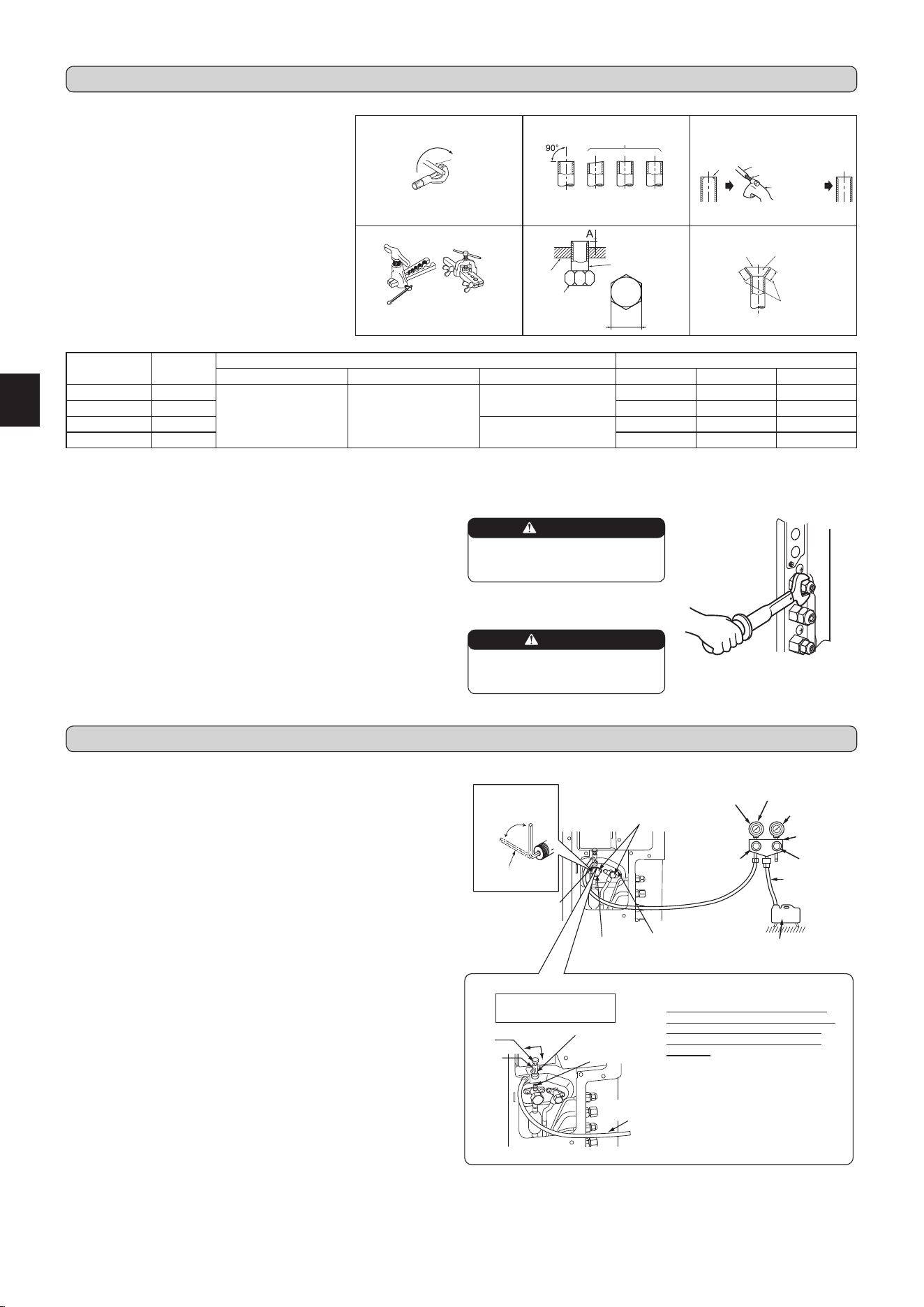
3-2. PIPE CONNECTION
1)Applyathincoatofrefrigerationoil(G)tothearedendsofthepipesandthe
pipe connections of the outdoor unit.
2) Align the center of the pipe with that of the pipe connections of the outdoor unit,
thenhandtightenthearenut3to4turns.
3)Tightenthearenutwithatorquewrenchasspeciedinthetable.
• Over-tightening maycause damage to the arenut, resultingin refrigerant
leakage.
• Besuretowrapinsulationaroundthepiping.Directcontactwiththebarepiping
may result in burns or frostbite.
3-3. INSULATION AND TAPING
1)Coverpipingjointswithpipecover.
2)Foroutdoorunitside,surelyinsulateeverypipingincludingvalves.
3) Using piping tape (E), apply taping starting from the entry of outdoor unit.
• Stoptheendofpipingtape(E)withtape(withadhesiveagentattached).
• Whenpipinghavetobearrangedthroughaboveceiling,closetorwherethe
temperature and humidity are high, wind additional commercially sold insulation
topreventcondensation.
WARNING
When installing the unit, securely
connect the refrigerant pipes before
starting the compressor.
CAUTION
When there are the ports which are
not used, make sure their nuts are
tightened securely.
Fig. 1 Fig. 2 Fig. 3
Fig. 4 Fig. 5 Fig. 6
TiltedUnevenBurred
Good
No good
Burr
Copper pipe
Spare reamer
Pipe cutter
Smooth all
around
Evenlength
all around
Inside is shin-
ing without any
scratches.
B
Flare nut
Die
Copper pipe
Clutch type
Flaring tool
Wing nut type
Copper
pipe
Pipe diameter
[inch (mm)]
B
[inch (mm)]
A [inch (mm)] Tightening torque
Clutch type tool for R410A Clutch type tool for R22 Wing nut type tool for R22 ft-Ib N•m kgf•cm
1/4 (ø6.35) 21/32 (17)
0 to 0.02
(0 to 0.5)
0.04 to 0.06
(1.0 to 1.5)
0.06 to 0.08
(1.5 to 2.0)
10 to 13 13.7 to 17.7 140 to 180
3/8 (ø9.52) 7/8 (22) 25 to 30 34.3 to 41.2 350 to 420
1/2 (ø12.7) 1-1/32 (26)
0.08 to 1.0
(2.0 to 2.5)
36 to 42 49.0 to 56.4 500 to 575
5/8 (ø15.88) 1-5/32 (29) 54 to 58 73.5 to 78.4 750 to 800
3-1. FLARING WORK
1) Cut the copper pipe correctly with pipe cutter. (Fig. 1, 2)
2)Completelyremoveallburrsfromthecutcrosssectionof
pipe. (Fig. 3)
• Aimthecopperpipedownwardwhileremovingburrsto
preventburrsfromdroppinginthepipe.
3)Removearenutsattachedtoindoorandoutdoorunits,
thenputthemonpipehaving completedburrremoval.
(Notpossibletoputthemonafteraringwork.)
4)Flaringwork (Fig.4,5).Firmly holdcopperpipe in the
dimension shown in the table. Select A inch (mm) from
the table according to the tool selected.
5)Check
• ComparethearedworkwithFig.6.
• Ifareisnotedtobedefective,cutoffthearedsection
anddoaringworkagain.
4-1.PURGINGPROCEDURESANDLEAKTEST
1)Removeserviceportcapofstopvalveonthesideoftheoutdoorunitgaspipe.
(Thestopvalvesarefullyclosedandcoveredincapsintheirinitialstate.)
2)Connectgaugemanifoldvalveandvacuumpumptoserviceportofstopvalve
on the side of the outdoor unit gas pipe.
3)Runthevacuumpump.(Vacuumizeformorethan15minutes.)
4)Check thevacuum withgauge manifold valve,then closegauge manifold
valve,andstopthevacuumpump.
5)Leaveasitisforoneortwominutes.Makesurethepointerofgaugemanifold
valveremainsinthesameposition.Conrmthatpressuregaugeshows-14.7
psi[Gauge](-0.101MPa).
6)Removegaugemanifoldvalvequicklyfromserviceportofstopvalve.
7)Fullyopenallstopvalvesonthegaspipeandtheliquidpipe.Operatingwithout
fully opening lowers the performance and this causes trouble.
8)Referto1-2.,andchargetheprescribedamountofrefrigerantifneeded.Be
sure to charge slowly with liquid refrigerant. Otherwise, composition of the
refrigerant in the system may be changed and affect performance of the air
conditioner.
9)Tightencapofserviceporttoobtaintheinitialstatus.
10
)Leaktest
3. FLARING WORK AND PIPE CONNECTION
4. PURGINGPROCEDURES,LEAKTEST,ANDTESTRUN
Stopvalve
forGAS
Stopvalvecap
(Torque 19.6 to
29.4N•m,200
to300kgf•cm)
Gaugemanifold
valve(forR410A)
Compound pressure
gauge (for R410A)
–0.101MPa
(–760mmHg)
Handle
Low
HandleHigh
Vacuumpump
(for R410A)
*Close
*Open
Hexagonalwrench
*4 to 5 turns
Stopvalve
forLIQUID
Pressure gauge
(for R410A)
Precautions when us-
ingthecontrolvalve
Whenattachingthecontrolvalve
totheserviceport,valvecoremay
deform or loosen if excess pres-
sure is applied. This may cause
gasleak.
Serviceport
Charge hose
(for R410A)
Body
Close
Open
Control
valve
A
Whenattachingthecontrolvalveto
theserviceport,makesurethatthe
valvecoreisinclosedposition,and
then tighten part A. Do not tighten
partAorturnthebodywhenvalve
core is in open position.
Serviceportcap
(Torque 13.7 to
17.7N•m,140 to
180kgf•cm)
Charge hose
(for R410A)
BH79A325H03_en.indd 5 2018/08/06 13:12:25
Loading ...
Loading ...
Loading ...