Loading ...
Loading ...
Loading ...
USER GUIDE
u-line.com
Water Hookup
Water Hookup
PREPARE PLUMBING
The water valve uses a standard 1/4” (6.35 mm)
compression fitting. U-Line recommends using accessory
water hook up kit – part # ULAWATERHOOKUP. The kit
includes a 10’ (3 m) braided flexible water supply line and
a brass hose fitting.
Plumbing installation must observe all state
and local codes. All water and drain connections
MUST BE made by a licensed/qualied plumbing
contractor. Failure to follow recommendations
and instructions may result in damage and/or
harm.
Water Supply Connection
When connecting the water supply, please note the
following:
• Before installing the unit and connecting to the cold
water supply, review the local plumbing codes.
• The water pressure should be between a minimum of
20 and a maximum of 120 psi (138 and 827 kPa).
• The water line MUST have a shut-o valve in the
supply line.
• The water line should be looped into 2 coils. This
will allow the unit to be removed for cleaning and
servicing. Make certain that the tubing is not pinched
or damaged during installation.
Connect to potable water supply only.
Do not use any plastic water supply line. The line
is under pressure at all times. Plastic may crack
or rupture with age and cause damage to your
home.
Do not use tape or joint compound when
attaching a braided exible water supply line
that includes a rubber gasket. The gasket
provides an adequate seal – other materials
could cause blockage of the valve.
Failure to follow recommendations and
instructions may result in damage and/or harm,
ooding or void the product warranty.
Use new hose set. Do not reuse old hose set.
Turn o water supply and disconnect electrical
supply to unit prior to installation.
Use caution when handling back panel. The edges
could be sharp.
Turn o water supply and disconnect electrical supply to
product prior to attempting installation.
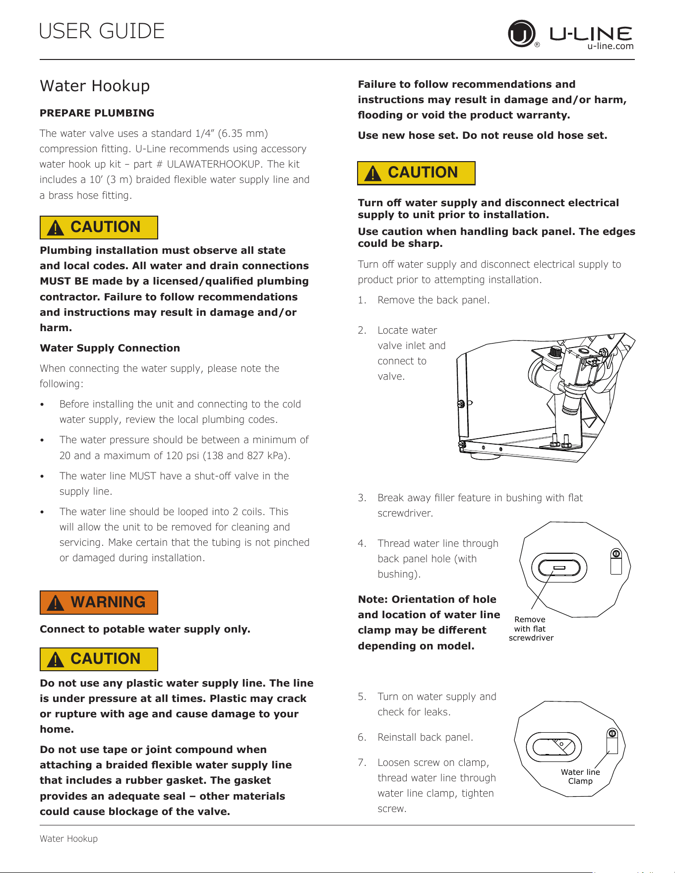
1. Remove the back panel.
2. Locate water
valve inlet and
connect to
valve.
3. Break away ller feature in bushing with at
screwdriver.
4. Thread water line through
back panel hole (with
bushing).
Note: Orientation of hole
and location of water line
clamp may be dierent
depending on model.
5. Turn on water supply and
check for leaks.
6. Reinstall back panel.
7. Loosen screw on clamp,
thread water line through
water line clamp, tighten
screw.
CAUTION
!
CAUTION
!
CAUTION
!
WARNING
!
Remove
with flat
screwdriver
Water line
Clamp
9
Loading ...
Loading ...
Loading ...