Loading ...
TEMPLATE
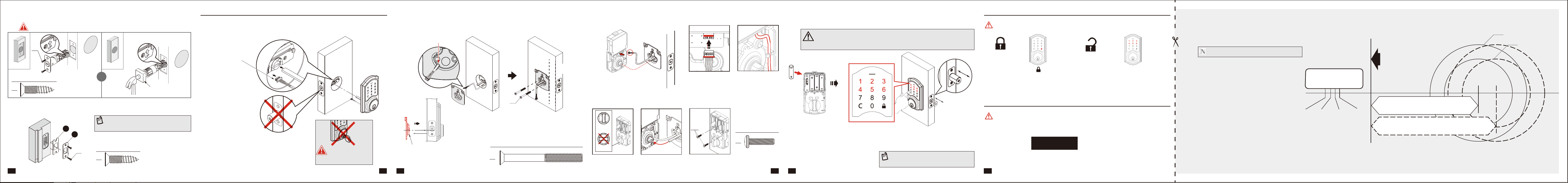
NOTE: Double check your product for the correct hole sizes.
The latch bolt should be
in retracted position.
AA
Slide the cable through the
notch in mounting plate.
BB
Hardware Used (Actual Size)
Note : The metal connector
side should face outward.
Connect the cable rmly
into connector port.
The cable must be arranged
as shown in the diagram.
Insert the torque blade into the
interior slot of the thumbturn.
BB
Insert screws and tighten.
CORRECT
WRONG
Keep the thumbturn in
vertical position.
CC
Hardware Used (Actual Size)
CC
Hardware Used (Actual Size)
CC
I
H
CC
Tap latch ush
AA
AA
AA
AA
Install batteries
CAUTION :
Please use four alkaline batteries for better performance. Be sure to insert them correctly by
matching the + and – polarity markings. Do not mix old batteries and new batteries or standard
(carbon-zinc) with alkaline batteries.
Test lock with door OPENED to avoid being locked out.
Enter default Master Code(
123456
).
The detection of the bolt direction takes
10 seconds to complete. Wait until the
Green LED lights up.
See the User Guide for additional information.
NOTE:
If Red LED lights up with 3 beeps, refer to
Troubleshooting section or contact
customer service for further assistance.
Step 3: Install Electronic Deadbolt Step 4: Test Lock
Step 5: Program Lock
Promptly change the Master Code before operating this lockset.
Install the latch
Install strike plate in door jamb
Insert screws and tighten.
Edge of door
08
09 10 11
06
07
OR
You must use the latch that was provided in the packaging.
Edge of door
Rotate torque blade to t in latch.
Cable goes underneath latch.
Fasten the mounting plate to door
Connect the cable rmly into connector port Install batteries and perform automatic bolt direction determination
Install interior assembly
Installing the lock assemblies
AA
Hardware Used (Actual Size)
Keep parallel
to door edge.
Wood block (not included)
To unlock
To lock
Enter default Master Code
123456
to unlock.
Press “ ” to lock.
NOTE:
Check the strike plate to make sure it is
properly aligned and clear so the bolt can freely
move in the hole.
1-3/4”
(45 mm)
1-3/8”
(35 mm)
1-9/16”
(40 mm)
2”
(51 mm)
Ø 2-1/8” (54 mm)
Ø 1-1/2” (38 mm)
Drill a 1” (25 mm) diameter
hole at the center of the door
edge.
Fold here.
Place on the door edge.
2-3/4” (70 mm)
2-3/8” (60 mm)
Backset
Backset
Drive-in latch
Do NOT leave the key in
the cylinder during
installation.
The bulged part of the mounting
plate must face towards the door.
Tighten the screws evenly.
Insert key and test latch. If latch does not extend or
retract smoothly, adjust Mounting Bolts (AA). Remove key
when nished and make sure the latch bolt is retracted.