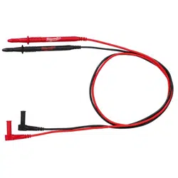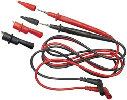
92PC TEST LEAD SET
MODEL NO: TA111.V2
Thank you for purchasing a Sealey product. Manufactured to a high standard, this product will, if used according to these instructions,
and properly maintained, give you years of trouble free performance.
IMPORTANT: PLEASE READ THESE INSTRUCTIONS CAREFULLY. NOTE THE SAFE OPERATIONAL REQUIREMENTS, WARNINGS & CAUTIONS. USE
THE PRODUCT CORRECTLY AND WITH CARE FOR THE PURPOSE FOR WHICH IT IS INTENDED. FAILURE TO DO SO MAY CAUSE DAMAGE AND/OR
PERSONAL INJURY AND WILL INVALIDATE THE WARRANTY. KEEP THESE INSTRUCTIONS SAFE FOR FUTURE USE.
1. SAFETY
1.1. PERSONAL PRECAUTIONS
9 When using the test leads, observe all normal safety rules concerning:
9 Protection against the dangers of electric current.
9 Protection of the test leads against misuse.
8 DO NOT use leads if damaged or if the internal wire is exposed in any way.
1.2. GENERAL SAFETY INSTRUCTIONS
WARNING! Never perform resistance measurements on live circuits. Only measure on disconnected circuits.
9 These test leads are designed to be used on automotive circuits only.
8 DO NOT use on 110V and 230V applications.
9 Familiarise yourself with the application and limitations of the test leads as well as the potential hazards.
IF IN ANY DOUBT CONSULT A QUALIFIED ELECTRICIAN.
9 When not in use, store the test leads in the case supplied.
9 Keep the work area clean, uncluttered and ensure there is adequate lighting. Keep tools and other items away from the engine and
ensure that you can see the working parts of the engine clearly.
9 Observe standard workshop safety procedures when using the test leads.
9 Consult the vehicle’s handbook for fuse positions and check if the fuse has blown. If the fuse has blown, rst establish the reason for
this before replacing with the same fuse type.
9 Ensure test leads are kept clear of hot surfaces and rotating parts.
9 Never apply voltage or current to the test leads that exceeds the specified maximum.
8 DO NOT use the test leads for any purpose other than for which they are designed.
8 DO NOT get the test leads wet, or use in damp or wet locations or areas where there is condensation.
2. INTRODUCTION
Comprehensive set of test leads and components suitable for testing, isolating and evaluating automotive electronic circuits. Includes standard
Ø4mm banana style plugs and sockets suitable for use with most diagnostic multimeters and test equipment. Supplied in sectioned storage case
for quick location of components.
3. SPECIFICATION
Model No: ...............................................................TA111.V2
Contents: Potentiometer; 5kΩ (x2), Alligator Clip (x2), Back Probe (x4),
LED 2-Colour Strobes (x2), SRS Connector (x2), 1:2 Connector (x2), 1:1
Connector/Cables (Piggy-Back) (x4), Probe (x2), Round Terminals with
Banana Socket; Male (x3)/Female (x3) - 1.5, 2, 3.5, 4mm, Flat Terminals with
Banana Socket; Male (x3)/Female (x3) - 0.7, 0.8, 1.2, 2, 2.5, 3, 5, 6mm
4. CONTENTS
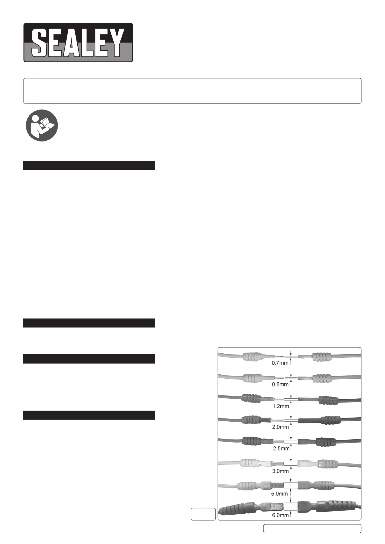
4.1. FLAT TERMINALS (fig.1)
0.7mm (Male/Female) + Female banana sockets (3pcs each)
0.8mm (Male/Female) + Female banana sockets (3pcs each)
1.2mm (Male/Female) + Female banana sockets (3pcs each)
2.0mm (Male/Female) + Female banana sockets (3pcs each)
2.5mm (Male/Female) + Female banana sockets (3pcs each)
3.0mm (Male/Female) + Female banana sockets (3pcs each)
5.0mm (Male/Female) + Female banana sockets (3pcs each)
6.0mm (Male/Female) + Female banana sockets (3pcs each)
Refer to
instruction
manual
TA111.V2 Issue:2 ( H,F) 21/09/23
Original Language Version
© Jack Sealey Limited
fig.
1
Original Language Version
© Jack Sealey Limited
TA111.V2 Issue:2 ( H,F) 21/09/23
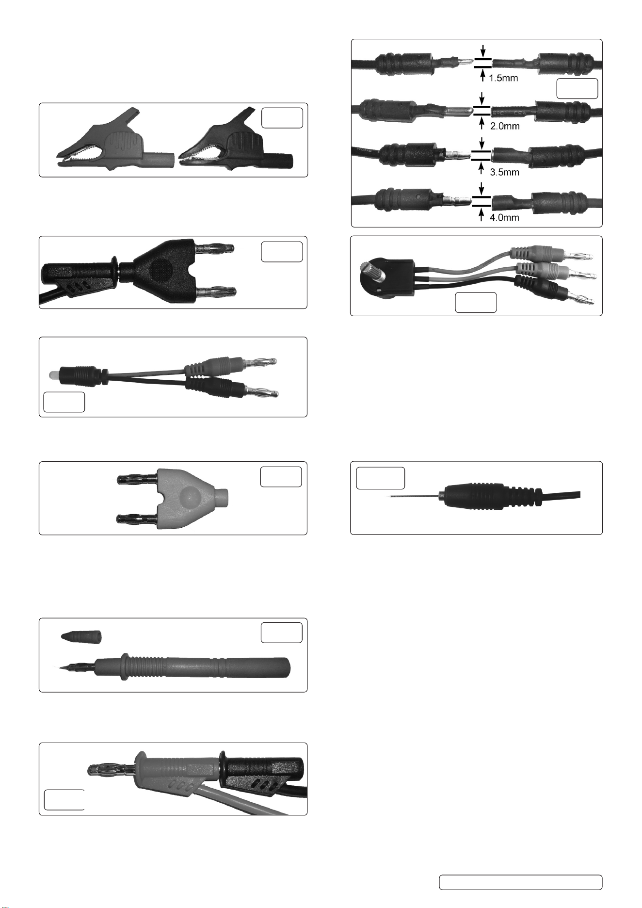
4.2. ROUND TERMINALS (fig.2)
1.5mm (Male/Female) + Female banana sockets (3pcs each)
2.0mm (Male/Female) + Female banana sockets (3pcs each)
3.5mm (Male/Female) + Female banana sockets (3pcs each)
4.0mm (Male/Female) + Female banana sockets (3pcs each)
4.3.
ALLIGATOR CLIPS
Two clips are supplied, one red (positive) and one black (negative).
The banana sockets at the back of the terminals will accept
the leads supplied or the probe (fig.7). Quantity: 2.
4.4. 1 TO 2 CONNECTOR 4.9 5KW POTENTIOMETER
Use in conjunction with various sensors such as those
for engine coolant temperature, oil temperature.
Quantity: 2
4.5.
LED STROBOSCOPE
Two colour, two way LED. LED changes colour in response
to the polarity. Quantity: 2.
4.6.
SRS CONNECTOR
Aids the setting up of a new SRS airbag and seat belt 4.10 BACK PROBE
triggers after an accident. Use to pierce insulation, to test for open circuit
break or poor connection. Quantity: 4
Maximum current 0.25A, above this value the connector
will burn out. Quantity: 2.
4.7.
PROBE
The probe has a 4mm banana socket in the end of the barrel
thus allowing connectivity with other components in the system.
Quantity: 2.
4.8.
MALE/FEMALE 1 to 1 CONNECTOR
Connectors are at either end of 100cm leads and allow a
one to one piggy-back connection. Quantity: 4.
fig.
2
fig.
3
fig.
4
fig.
9
fig.
5
fig.
10
fig.
6
fig.
7
fig.
8

Sealey Group, Kempson Way, Suffolk Business Park, Bury St Edmunds, Suffolk. IP32 7AR
01284 757500 sales@sealey.co.uk www.sealey.co.uk
ENVIRONMENT PROTECTION
Recycle unwanted materials instead of disposing of them as waste. All tools, accessories and packaging should be sorted, taken to
a recycling centre and disposed of in a manner which is compatible with the environment. When the product becomes completely
unserviceable and requires disposal, drain any fluids (if applicable) into approved containers and dispose of the product and fluids
according to local regulations.
Original Language Version
© Jack Sealey Limited
REGISTER YOUR
PURCHASE HERE
WEEE REGULATIONS
Dispose of this product at the end of its working life in compliance with the EU Directive on Waste Electrical and Electronic
Equipment (WEEE). When the product is no longer required, it must be disposed of in an environmentally protective way.
Contact your local solid waste authority for recycling information.
TA111.V2 Issue:2 ( H,F) 21/09/23