
Full-Color LED Display Controller
User Manual

Legal Informaon
©2020 Hangzhou Hikvision Digital Technology Co., Ltd. All rights reserved.
About this Manual
The Manual includes instrucons for using and managing the Product. Pictures, charts, images and
all other informaon hereinaer are for descripon and explanaon only. The informaon
contained in the Manual is subject to change, without noce, due to rmware updates or other
reasons. Please
nd the latest version of this Manual at the Hikvision website ( hps://
www.hikvision.com/ ).
Please use this Manual with the guidance and assistance of professionals trained in
supporng the
Product.
Trademarks
and other Hikvision's trademarks and logos are the properes of
Hikvision in various
jurisdicons.
Other trademarks and logos menoned are the properes of their respecve owners.
: The terms HDMI and HDMI High-Denion Mulmedia Interface, and the HDMI
Logo are trademarks or registered trademarks of HDMI Licensing Administrator, Inc. in the United
States and other countries.
Disclaimer
TO THE MAXIMUM EXTENT PERMITTED BY APPLICABLE LAW, THIS MANUAL AND THE PRODUCT
DESCRIBED, WITH ITS HARDWARE, SOFTWARE AND FIRMWARE, ARE PROVIDED “AS IS” AND “WITH
ALL FAULTS AND ERRORS”. HIKVISION MAKES NO WARRANTIES, EXPRESS OR IMPLIED, INCLUDING
WITHOUT LIMITATION, MERCHANTABILITY, SATISFACTORY QUALITY, OR FITNESS FOR A PARTICULAR
PURPOSE. THE USE OF THE PRODUCT BY YOU IS AT YOUR OWN RISK. IN NO EVENT WILL HIKVISION
BE LIABLE TO YOU FOR ANY SPECIAL, CONSEQUENTIAL, INCIDENTAL, OR INDIRECT DAMAGES,
INCLUDING, AMONG OTHERS, DAMAGES FOR LOSS OF BUSINESS PROFITS, BUSINESS
INTERRUPTION, OR LOSS OF DATA, CORRUPTION OF SYSTEMS, OR LOSS OF DOCUMENTATION,
WHETHER BASED ON BREACH OF CONTRACT, TORT (INCLUDING NEGLIGENCE), PRODUCT LIABILITY,
OR OTHERWISE, IN CONNECTION WITH THE USE OF THE PRODUCT, EVEN IF HIKVISION HAS BEEN
ADVISED OF THE POSSIBILITY OF SUCH DAMAGES OR LOSS.
YOU ACKNOWLEDGE THAT THE NATURE OF INTERNET PROVIDES FOR INHERENT SECURITY RISKS,
AND HIKVISION SHALL NOT TAKE ANY RESPONSIBILITIES FOR ABNORMAL OPERATION, PRIVACY
LEAKAGE OR OTHER DAMAGES RESULTING FROM CYBER-ATTACK, HACKER ATTACK, VIRUS
INSPECTION, OR OTHER INTERNET SECURITY RISKS; HOWEVER, HIKVISION WILL PROVIDE TIMELY
TECHNICAL SUPPORT IF REQUIRED.
YOU AGREE TO USE THIS PRODUCT IN COMPLIANCE WITH ALL APPLICABLE LAWS, AND YOU ARE
SOLELY RESPONSIBLE FOR ENSURING THAT YOUR USE CONFORMS TO THE APPLICABLE LAW.
ESPECIALLY, YOU ARE RESPONSIBLE, FOR USING THIS PRODUCT IN A MANNER THAT DOES NOT
Full-Color LED Display Controller User Manual
i

INFRINGE ON THE RIGHTS OF THIRD PARTIES, INCLUDING WITHOUT LIMITATION, RIGHTS OF
PUBLICITY, INTELLECTUAL PROPERTY RIGHTS, OR DATA PROTECTION AND OTHER PRIVACY RIGHTS.
YOU SHALL NOT USE THIS PRODUCT FOR ANY PROHIBITED END-USES, INCLUDING THE
DEVELOPMENT OR PRODUCTION OF WEAPONS OF MASS DESTRUCTION, THE DEVELOPMENT OR
PRODUCTION OF CHEMICAL OR BIOLOGICAL WEAPONS, ANY ACTIVITIES IN THE CONTEXT RELATED
TO ANY NUCLEAR EXPLOSIVE OR UNSAFE NUCLEAR FUEL-CYCLE, OR IN SUPPORT OF HUMAN
RIGHTS ABUSES.
IN THE EVENT OF ANY CONFLICTS BETWEEN THIS MANUAL AND THE APPLICABLE LAW, THE LATER
PREVAILS.
Full-Color LED Display Controller User Manual
ii
Regulatory Informaon
FCC Informaon
Please take aenon that changes or modicaon not expressly approved by the party responsible
for compliance could void the user's authority to operate the equipment.
FCC compliance: This equipment has been tested and found to comply with the limits for a Class A
digital device, pursuant to part 15 of the FCC Rules. These limits are designed to provide
reasonable
protecon against harmful interference when the equipment is operated in a
commercial environment. This equipment generates, uses, and can radiate radio frequency energy
and, if not installed and used in accordance with the
instrucon manual, may cause harmful
interference to radio communicaons. Operaon of this equipment in a residenal area is likely to
cause harmful interference in which case the user will be required to correct the interference at his
own expense.
FCC Condions
This device complies with part 15 of the FCC Rules. Operaon is subject to the following two
condions:
1. This device may not cause harmful interference.
2. This device must accept any interference received, including interference that may cause
undesired
operaon.
EU Conformity Statement
This product and - if applicable - the supplied accessories too are marked with
"CE" and comply therefore with the applicable harmonized European
standards listed under the EMC Direcve 2014/30/EU, the RoHS Direcve
2011/65/EU.
2012/19/EU (WEEE direcve): Products marked with this symbol cannot be
disposed of as unsorted municipal waste in the European Union. For proper
recycling, return this product to your local supplier upon the purchase of
equivalent new equipment, or dispose of it at designated
collecon points.
For more
informaon see: hp://www.recyclethis.info .
2006/66/EC (baery direcve): This product contains a baer y that cannot be
disposed of as unsorted municipal waste in the European Union. See the
product documentaon for specic baery informaon. The baery is
marked with this symbol, which may include
leering to indicate cadmium
(Cd), lead (Pb), or mercury (Hg). For proper recycling, return the
baery to
your supplier or to a designated
collecon point. For more informaon see:
hp://www.recyclethis.info .
Full-Color LED Display Controller User Manual
iii

Industry Canada ICES-003 Compliance
This device meets the CAN ICES-3 (A)/NMB-3(A) standards requirements.
Full-Color LED Display Controller User Manual
iv
Preface
Applicable Models
This guide is applicable to full-color LED display controller.
Symbol Convenons
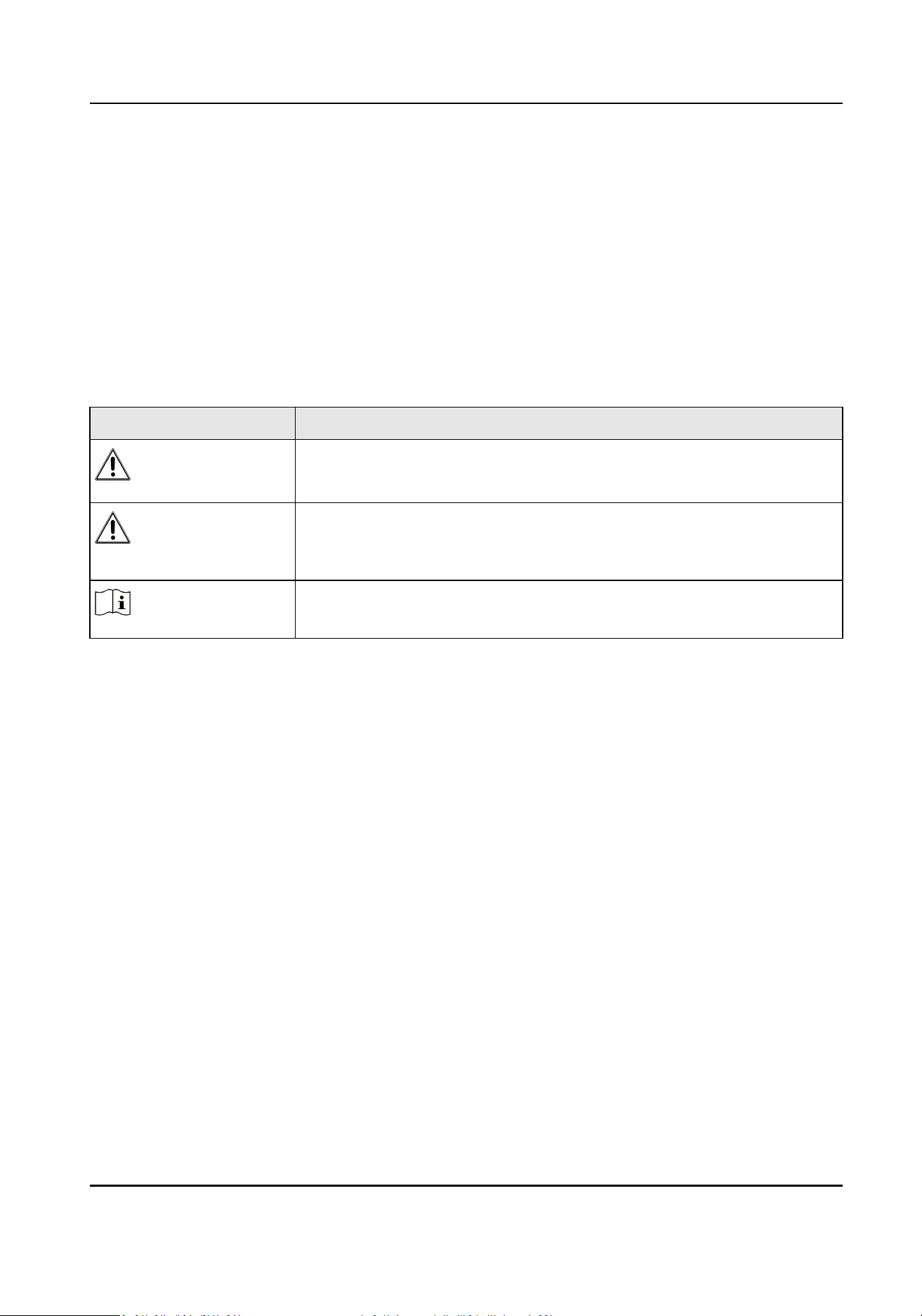
The symbols that may be found in this document are dened as follows.
Symbol Descripon
Danger
Indicates a hazardous situaon which, if not avoided, will or could
result in death or serious injury.
Cauon
Indicates a potenally hazardous situaon which, if not avoided, could
result in equipment damage, data loss, performance degradaon, or
unexpected results.
Note
Provides addional informaon to emphasize or supplement
important points of the main text.
Safety Instrucon
• Proper conguraon of all passwords and other security sengs is the responsibility of the
installer and/or end-user.
• In the use of the product, you must be in strict compliance with the electrical safety
regulaons
of the naon and region. Please refer to technical specicaons for detailed informaon.
• Input voltage should meet both the SELV (Safety Extra Low Voltage) and the Limited Power
Source with 100~240 VAC according to the IEC60950-1 standard. Please refer to technical
specicaons for detailed informaon.
• Do not connect several devices to one power adapter as adapter overload may cause over-
heang
or a re hazard.
• Please make sure that the plug is rmly connected to the power socket.
• If smoke, odor or noise rise from the device, turn
o the power at once and unplug the power
cable, and then please contact the service center.
Full-Color LED Display Controller User Manual
v

Contents
Chapter 1 Product Introducon .................................................................................................. 1
1.1 Overview ................................................................................................................................ 1
1.2 Main Features ........................................................................................................................ 1
1.3 Physical Interface ................................................................................................................... 2
Chapter 2 Device Acvaon and Login ........................................................................................ 4
2.1 Acvate the Device ................................................................................................................ 4
2.2 Add Power Distribuon Cabinet ............................................................................................ 6
2.3 Login ...................................................................................................................................... 6
Chapter 3 Client
Conguraon and Operaon ............................................................................ 7
3.1 Wizard .................................................................................................................................... 7
3.1.1 Display Aribute Conguraon .................................................................................... 7
3.1.2
Congure Signal Cable .................................................................................................. 8
3.2 Signal Input Type Conguraon ........................................................................................... 10
3.3 Display Adjustment .............................................................................................................. 10
3.3.1 Correct Screen/Seam .................................................................................................. 10
3.3.2
Congure Screen Color ............................................................................................... 15
3.3.3 Congure Brightness ................................................................................................... 16
3.3.4
Congure Image Enhancement ................................................................................... 16
3.3.5 Input Capability ........................................................................................................... 17
3.4 Volume Adjustment ............................................................................................................. 18
3.5
Congure a Scene ................................................................................................................ 19
3.6 Add Device Alias ................................................................................................................... 20
3.7 Congure Message .............................................................................................................. 20
3.8
Congure OSD ...................................................................................................................... 21
3.9 Congure Network ............................................................................................................... 21
3.10 Congure No-Signal Screensaver ....................................................................................... 22
Full-Color LED Display Controller User Manual
vi

3.11 Congure On/o Image ..................................................................................................... 23
3.12 Congure Mulcast Control ............................................................................................... 23
3.13
Congure Video Window Opening .................................................................................... 24
3.14 Congure Screen Splicing ................................................................................................... 25
Chapter 4 Device Maintenance ................................................................................................. 27
4.1 Screen Defecve Pixel Detecon ......................................................................................... 27
4.2 Test Screen Color ................................................................................................................. 27
4.3 Congure Advanced Image .................................................................................................. 28
4.4 Congure Dehumidicaon ................................................................................................. 28
4.5 Congure Work Mode .......................................................................................................... 29
4.6 Detect Screen Status ............................................................................................................ 30
4.7 View Device Informaon ...................................................................................................... 30
4.8 View Receiving Card
Informaon ......................................................................................... 30
4.9 Upgrade ............................................................................................................................... 31
4.9.1 Local Upgrade ............................................................................................................. 31
4.9.2 Online Upgrade ........................................................................................................... 32
Chapter 5 System Maintenance ................................................................................................ 34
5.1 Import/Export
Conguraon File ......................................................................................... 34
5.2 Export Conguraon File ..................................................................................................... 34
5.3 Search and Export Logs ........................................................................................................ 34
5.4 Sync Time ............................................................................................................................. 35
5.5 Remote Reboot .................................................................................................................... 35
5.6 Restore Factory
Sengs ....................................................................................................... 35
5.7 Restore User Default Sengs .............................................................................................. 35
Chapter 6 Local Conguraon and Operaon ........................................................................... 36
6.1
Mul-funconal Card (Oponal) .......................................................................................... 36
6.2 Remote Control Funcons ................................................................................................... 36
Chapter 7 FAQ .......................................................................................................................... 38
Full-Color LED Display Controller User Manual
vii

7.1 Full Screen is Unlit ................................................................................................................ 38
7.2 Image is Incomplete or in Wrong Posion ........................................................................... 38
7.3 Full-screen Image Flashes or Vibrates .................................................................................. 39
7.4 Spots/Strips Exist in Full-screen Image ................................................................................ 39
7.5 Certain Unit Image Flashes or Has Spots ............................................................................. 39
7.6 Certain Unit Screen is Unlit .................................................................................................. 39
7.7 Certain Module or Row of Modules are Unlit in Unit .......................................................... 40
7.8 Screen Display Error When Smart
Sengs .......................................................................... 40
7.9 Searching Online Device Fail ................................................................................................ 40
Full-Color LED Display Controller User Manual
viii

Chapter 1 Product Introducon
1.1 Overview
LED Full-Color Display Controller can be used with the full-color display units to achieve the
seamless joinng of the video wall in any dimensions. It is applicable to the meeng rooms, studio,
gym, airport, bank, adversement, family cinema, etc.
1.2 Main Features
Basic Features
• 16 Gigabit Ethernet output ports, each with 4096 × 2160@60 Hz signal source input at most
• Super long subtle display, and le-jusfying and right-jusfying, centering and scroll display
•
Automac dehumidicaon to protect damp led, and three humidity modes suit the areas of
dierent humidity
• Quick and convenient
operaon by remote client soware
• Remote control with remote UI menu on the display unit
• Obtains IP address on random network segment to make sure no conicts among IPs and
network security
• Scene saving, and free switching with custom pictures and
subtles displayed on the windows of
both sides
• Quick and convenient adjustment of display brightness
•
Mulcast unied control of mul devices
• 3D signal available with 3D signal transmier and glasses equipped, single device with 3840 ×
1080 load capability at most
• Ezviz upgrade
• Audio in and audio out
Specic Features
• Mul-controller cascade display, mulcast control to realize synchronizaon
Superior Image Processing
• 16 bit depth of processing, low light and high grey to restore the colors of original images
• 3840 Hz high refresh rate, nanosecond response
me, and smooth video pictures
• Automac brightness and self-adapon to environmental lightness (with mul-funconal card)
• Image color temperature adjustment with standard, cold, warm, custom colors selectable
• Highly reliable pixel-by-pixel screen
correcon to ensure the consistency between brightness and
chromacity
• Manual visual piece revision to dilute and smooth the gap
• Image enhancement adjustment to improve the visual display
Full-Color LED Display Controller User Manual
1
Powerful System Funcons
• DVI, DP, and 2 HDMI signal source input, and HDMI loop output available
• HD signal input at up to 4096 × 2160@60 Hz (4K) and 4K point-to-point output
• Image scaling available
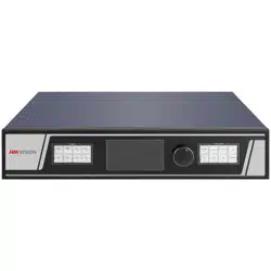
1.3 Physical Interface
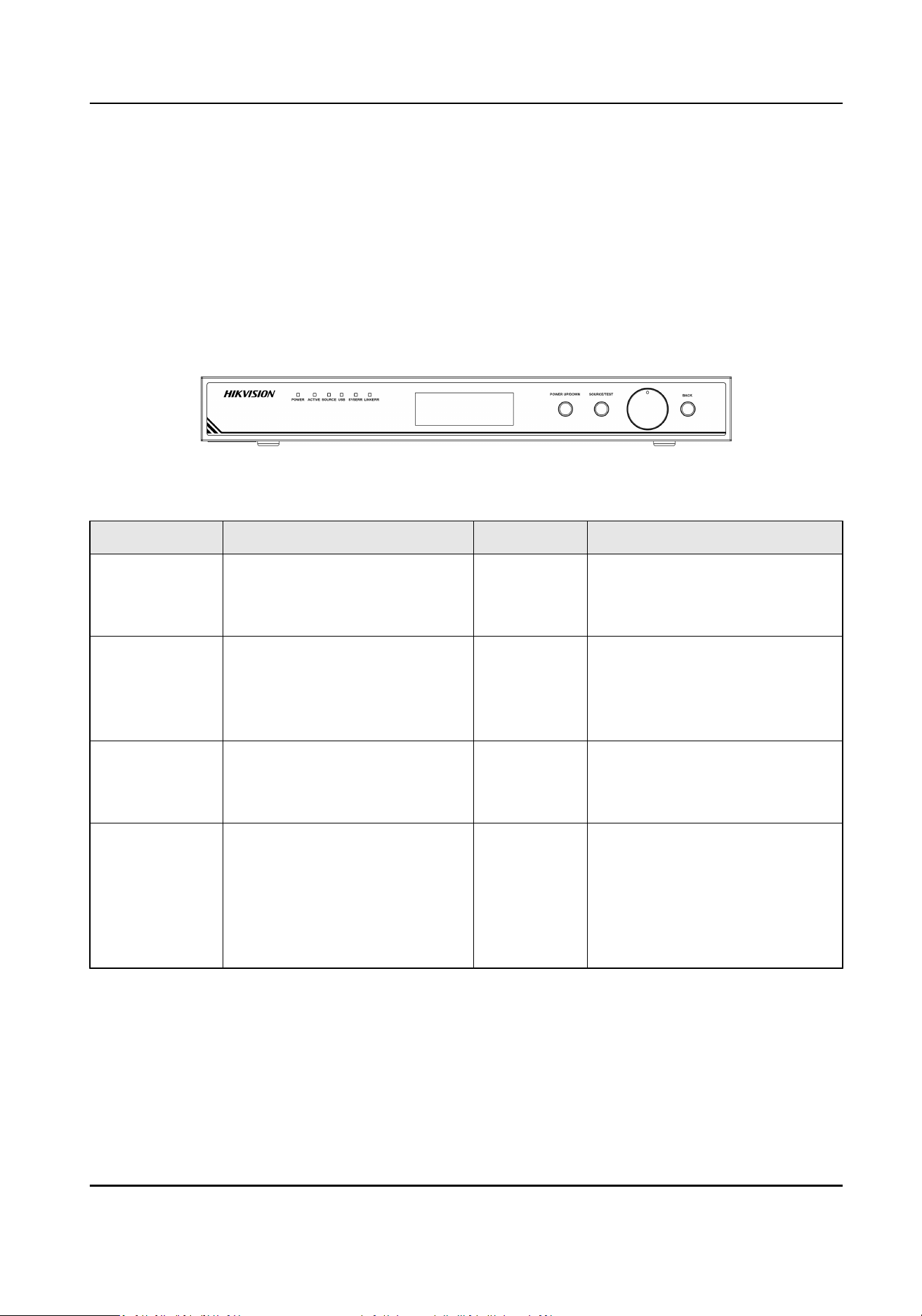
Front Panel
Figure 1-1 Front Panel Interface
Table 1-1 Interface Descripon of Front Panel
Indicator Descripon Indicator Descripon
POWER Power indicator
• Red: be in the sleep mode
• Green: work normally
ACTIVE Acve status indicator
Flickers green when the device
is powered on
SOURCE Signal source status indicator
• Steady on: with signal source
input
• Unlit: no signal source input
USB USB indicator
• Steady on: with USB inserted
• Unlit: no USB inserted
SYSERR System error indicator
Steady on green when system
error occurs
LINKERR Link error indicator
Steady on green when the
receiving card is oine
LCD Panel Display informaons such as
brightness, device IP, input/
output resoluon, signal source
type, menu lock status
Knob • Normal Mode (not the Menu
Mode): rotate right/le to
adjust brightness
• Menu Mode: rotate
right/le
to select menu item; press to
select or enter next menu
Full-Color LED Display Controller User Manual
2
Indicator Descripon Indicator Descripon
BACK • Long press: unlock the menu
lock and press the knob to
enter menu mode
• Short press: back to the
previous menu or the main
menu
SOURCE/
TEST
• Long press: enter the image
test mode
• Short press: switch the signal
source
POWER UP/
DOWN
• Long press: device in sleep
• Short press: awake the
device
—— ——
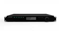
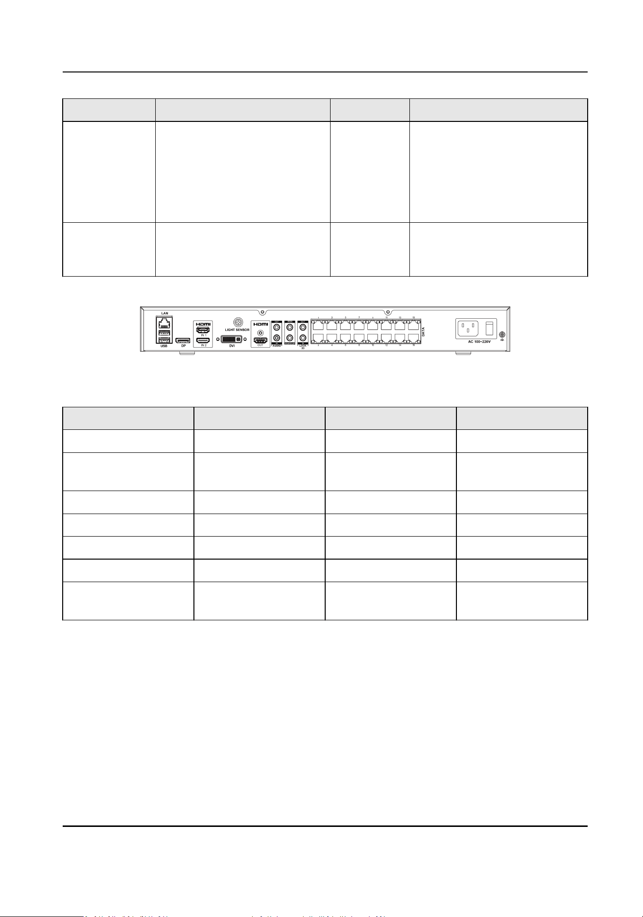
Rear Panel
Figure 1-2 Rear Panel Interface
Table 1-2 Interface Descripon of Rear Panel
Interface Descripon Interface Descripon
LAN Network signal input USB USB interface
DP DP interface HDMI IN 1/IN 2 HDMI signal input 1/
input 2
HDMI OUT HDMI signal output LIGHT SENSOR Light sensor interface
DVI DVI interface AUDIO IN/OUT Audio input/output
IR IN Infrared input WAKEUP Wakeup interface
3D OUT 3D signal output 3D IN 3D signal input
DATA 16 network port
output
Power 110 to 220 VAC
Full-Color LED Display Controller User Manual
3
Chapter 2 Device Acvaon and Login
2.1 Acvate the Device
In order to protect personal account privacy and reinforce system/data security, you need to set
login password and acvate the device for your rst login.
Before You Start
• The client soware has been installed correctly.
• PC and the device are in the same network segment.
Steps
1. Run the client .
Figure 2-1 Register
2. Click Online Device to show all online devices in the current network segment.
Full-Color LED Display Controller User Manual
4
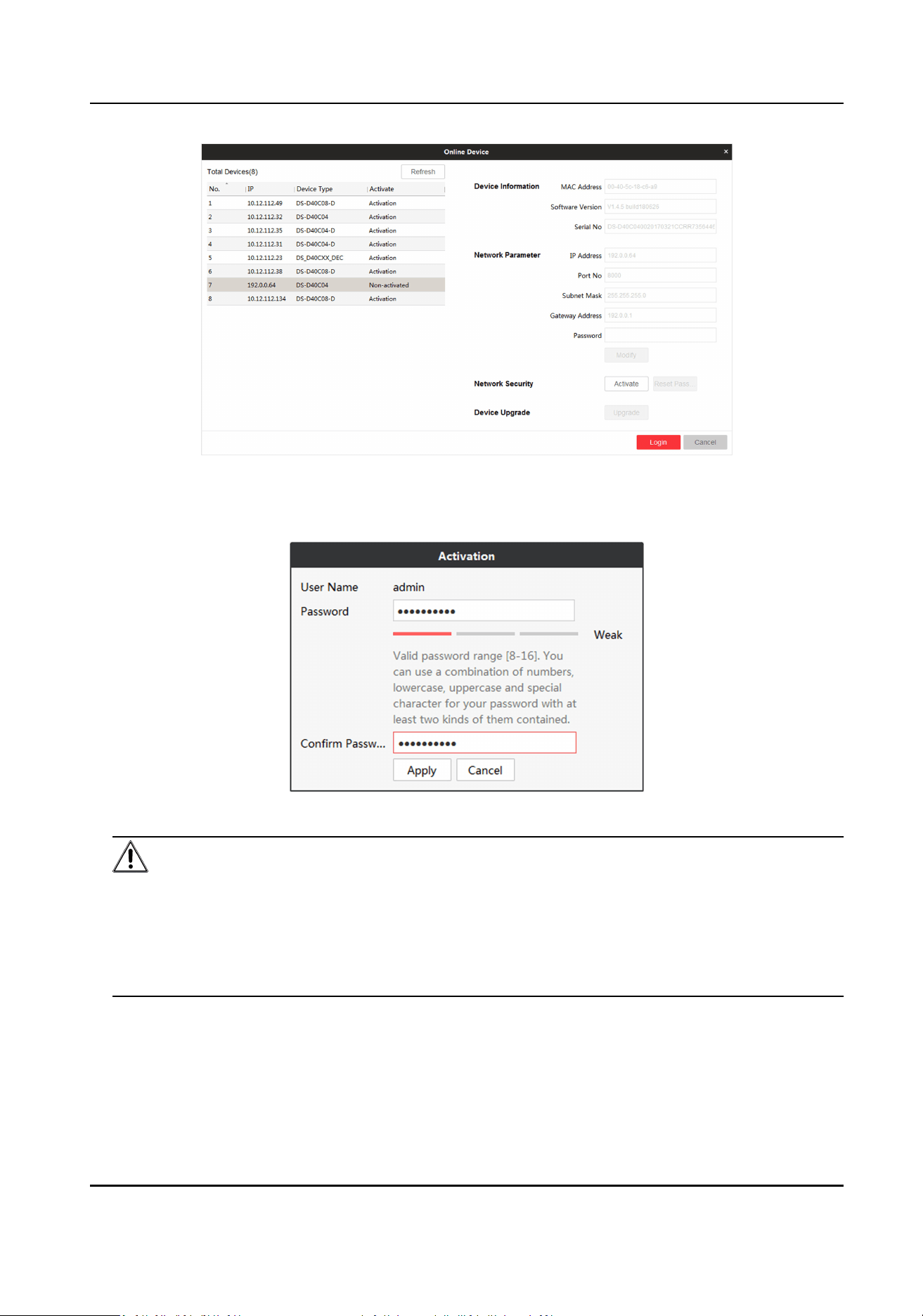
Figure 2-2 Acvate Online Device
3. Select the device to be acvated and click Acvate.
4. Enter Password and
Conrm Password in the popup window.
Figure 2-3 Acvaon
Cauon
We highly recommend you create a strong password of your own choosing (Using a minimum of
8 characters, including at least three of the following categories: upper case leers, lower case
leers, numbers, and special characters.) in order to increase the security of your product. And
we recommend you reset your password regularly, especially in the high security system,
reseng the password monthly or weekly can beer protect your product.
5. Click Apply to acvate the device.
6. Select the
acvated device in Online Device interface.
7. Modify network parameters and enter Password.
8. Click Modify to save the
modicaons.
Full-Color LED Display Controller User Manual
5
Note
If the network segment which device connected has DHCP funcon, it will allocate IP by default,
please skip step 6, 7 and 8.
2.2 Add Power Distribuon Cabinet
You can add a power distribuon cabinet as needed. The client can turn on/o the screen remotely
aer adding the power distribuon cabinet.
Steps
1. Double click LED Display Controller to run the client.
2. Click Power
Distribuon Cabinet Cong.
Figure 2-4 Login
3. Enter IP and port No. of power distribuon cabinet.
4. Click OK.
5. Enable Power
Distribuon Cabinet Cong.
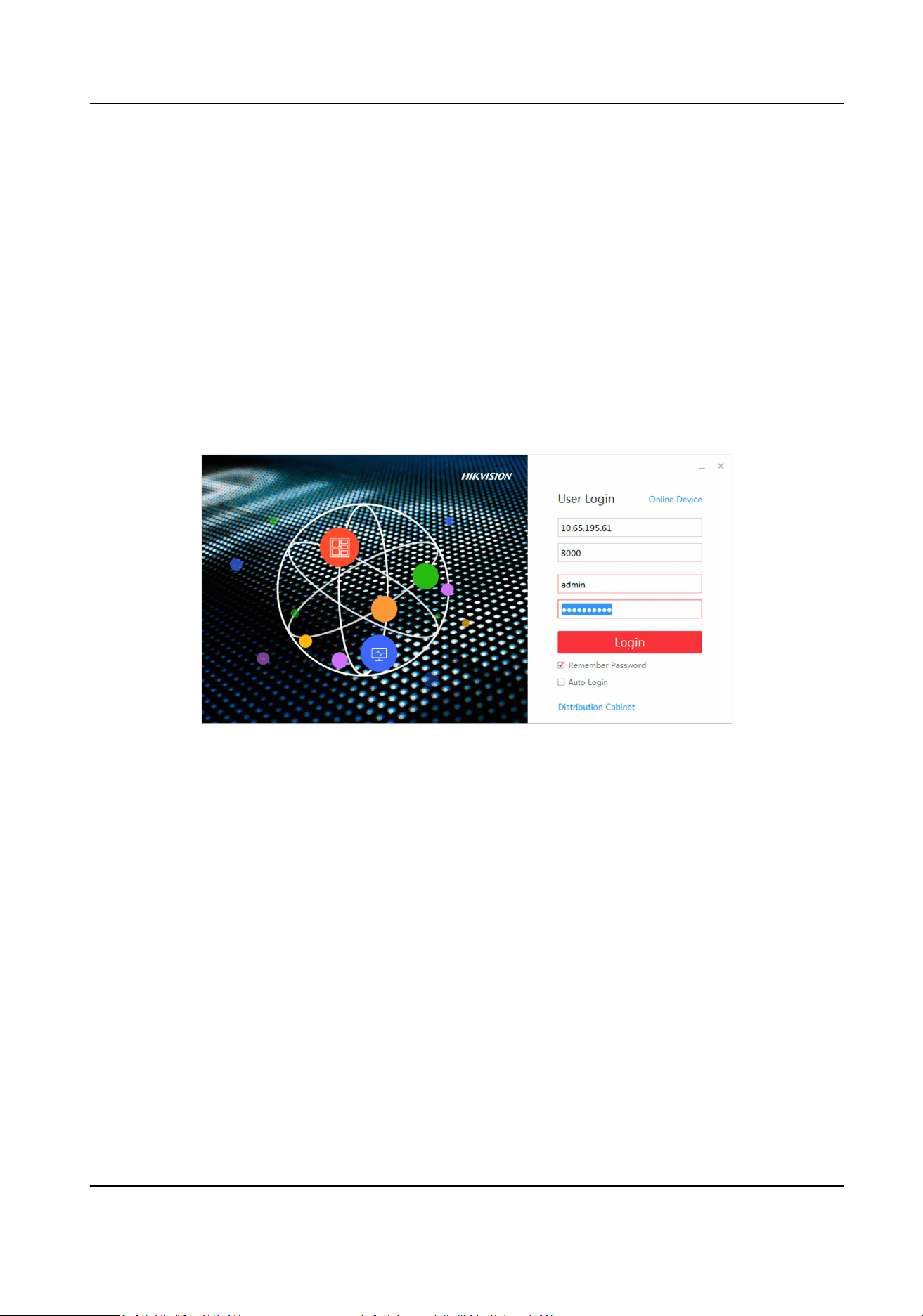
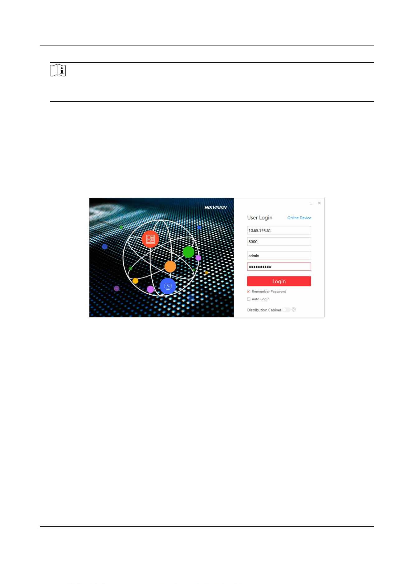
2.3 Login
Before any operaon, you need to log into the LED client server.
Steps
1. Run the client to enter the login interface.
2. Enter IP Address, Port No, User Name, and Password.
3.
Oponal: Check remember password to remember the login password, so there is no need to
enter password for the next login.
4.
Oponal: Check Auto Login to Log into the client automacally.
5. Click Login.
Full-Color LED Display Controller User Manual
6
Chapter 3 Client Conguraon and Operaon
3.1 Wizard
For the rst login, the client will pop up a wizard, including display aribute conguraon and
signal cable conguraon. Set the parameters as needed, and the client can recognize the screen
parameters automacally when you log in the next me.
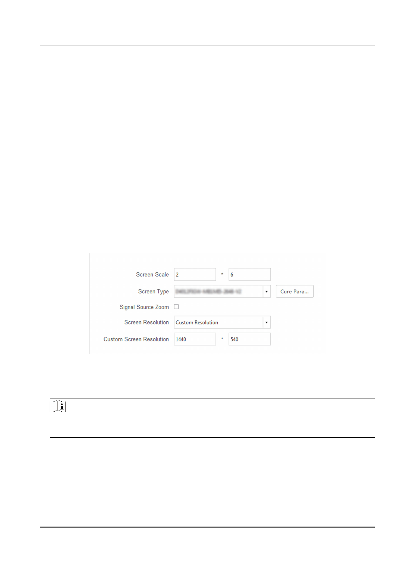
3.1.1 Display Aribute Conguraon
You can congure some basic parameters in the display aribute window, such as screen type,
screen scale, screen
resoluon and other parameters.
Screen
Conguraon
Congure screen scale and type, select signal source type as needed.
Figure 3-1 Display Aributes
Screen Scale
Set rows and columns of the screen according to the actual situaon.
Note
Each screen contains 2 receiving cards. If the actual screen size is 2 × 2, you need to set the scale
as 2 × 4.
Screen Type
Select it according to the screen type and material number. Or click Load from Screen to select
the screen type and material number.
Cure Parameters
Full-Color LED Display Controller User Manual
7
Save parameters in the receiving card to ensure your screen displays properly aer next reboot.
Congure Screen Resoluon
Aer conguring the screen resoluon, the display image can match the actual screen resoluon.
It can reduce the image loss and paral black screen caused by resoluon.
Steps
1. Enter Display
Aribute interface.
2. Check Signal Resource Zoom.
3. Select Screen
Resoluon.
-
Select
resoluon in Screen Resoluon.
-
If there is no appropriate
resoluon n the Screen Resoluon, you can select Custom
Resoluon in Screen Resoluon, and enter resoluon in Custom Screen Resoluon.
Note
• The width of the custom
resoluon should be a mulple of 4.
• Uncheck Signal Resource Zoom in splcing and controlling scene.
What to do next
Click Next and congure signal cable.
3.1.2
Congure Signal Cable
Congure signal cable according to the actual receiving card connecon between LED cabinets.
Steps
Note
Aer conguring the screen scale, LED screen will show the signal cable connecon. The
connecon of client signal cables must match the screen connecon.
1. Go to the Signal Cable Conguraon interface.
-
Click Next in the Display Aribute interface.
-
Click Basic
Conguraon → Signal Cable Conguraon .
2. Check Display Actual Lines on Screen. You need to connect the cable according to the
posion
prompt on the screen.
3. Select sending port below Please select sending port to connect.
Note
The locaon prompt of each screen will indicates you to connect the signal cable. If the poson
prompt is 2-1, the screen is the rst screen to connect to No.2 sending port.
Full-Color LED Display Controller User Manual
8
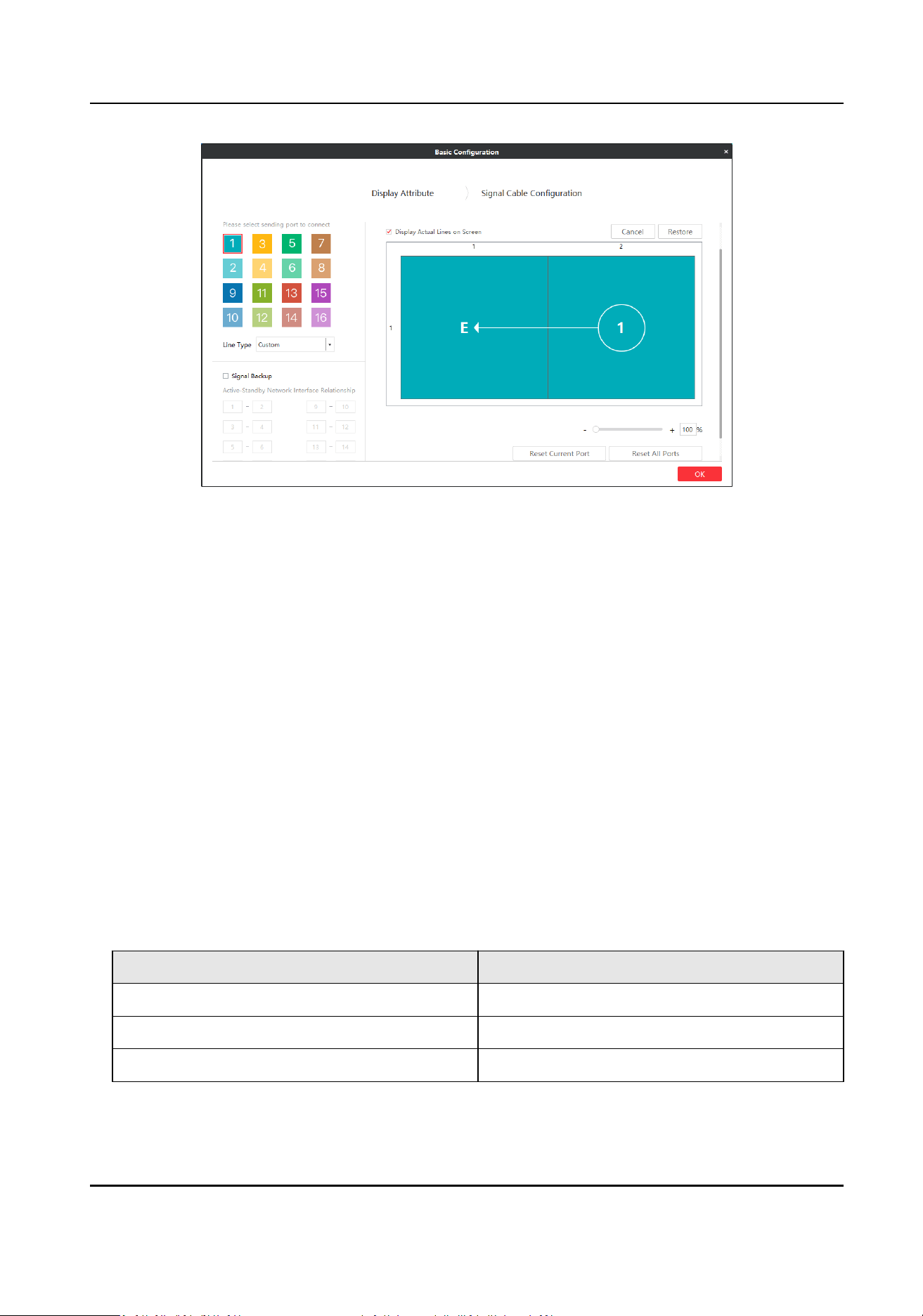
Figure 3-2 Signal Cable Conguraon
4. Connect signal line.
-
Click the screen on the right side of the interface to connect signal line.
-
Select Line Type, and select
starng port and end port on the right side of the interface.
5. Right-click on the right side of the interface aer connecon.
6. Select Complete Signal Cable Connecon.
7. Click Save.
Port
conguraon informaon set. will pop up aer the signal cable is connected.
Other
Operaon
Supports some auxiliary operaons to complete the signal cable connecon.
Copy Image
Enable Copy Image as needed, and
ll the number of images (the number of screens).
According to the actural lines displayed on screen, congure signal cables in every image/screen
on the client. For more informaon about how to congure signal cables, refer to Congure
Signal Cable .
Table 3-1 Maximum Number of Images for
Dierent Sending Card Type
Sending Card Type Maximum Number of Images
DS-D42C16 8
DS-D42C08 4
DS-D42C04 2
Sending Port
Full-Color LED Display Controller User Manual
9
Port of sending card is applied to communicate between sending card and receiving card. The
receiving card connected by signal sending port is Card1, the receiving card connected to the
rst sending card is Card2, and so on.
Cancel
Cancel last operaon.
Restore
Resume last operaon.
Reset Current Port
Cancel all sengs of current signal sending port.
Reset All Ports
Cancel sengs of all signal sending ports.
Signal Backup
Input signals by two channels to ensure signal stability.
Note
If Signal Backup checked, the relaon between the main and sub ports should be the same as that
of the client.
3.2 Signal Input Type Conguraon
Select the signal source type in the upper right corner of Display Status. You should select the
signal source according to the sending card resoluon.
Note
Dierent signal source may result in dierent resoluon.
3.3 Display Adjustment
Screen can get best display eects by conguring image parameters, brightness and enhancement,
screen display parameters, etc.
3.3.1 Correct Screen/Seam
You can correct screen and seam manually or in a batch to deliver beer LED display eects.
Correct Screen Manually
Correct display parameters of LED screens to achieve the same display eects.
Full-Color LED Display Controller User Manual
10
Steps
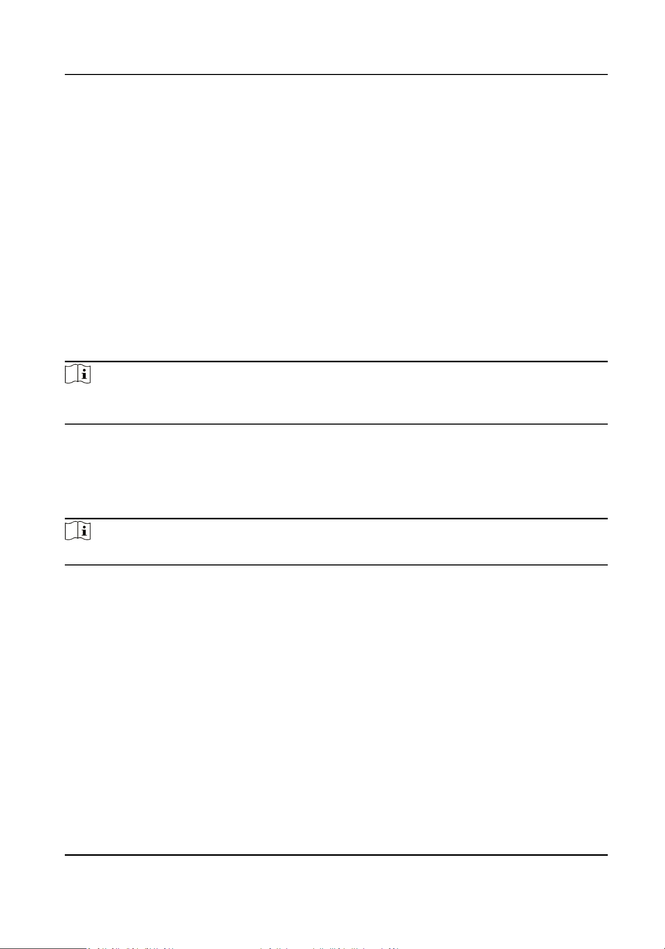
1. Click Screen Adjustment → Advanced
Operaon → Correcon → Manual Correcon .
Figure 3-3 Correct Screen Manually
2. Select Enable Correcon.
3. Select Screen in
Correcon. Drag the bar of Minimum Eecve Correcon Value and the data
bigger than the set value can be corrected.
4. Select area to correct.
-
Check Show Module and select the module to correct.
-
Uncheck Show Module and select the screen to correct.
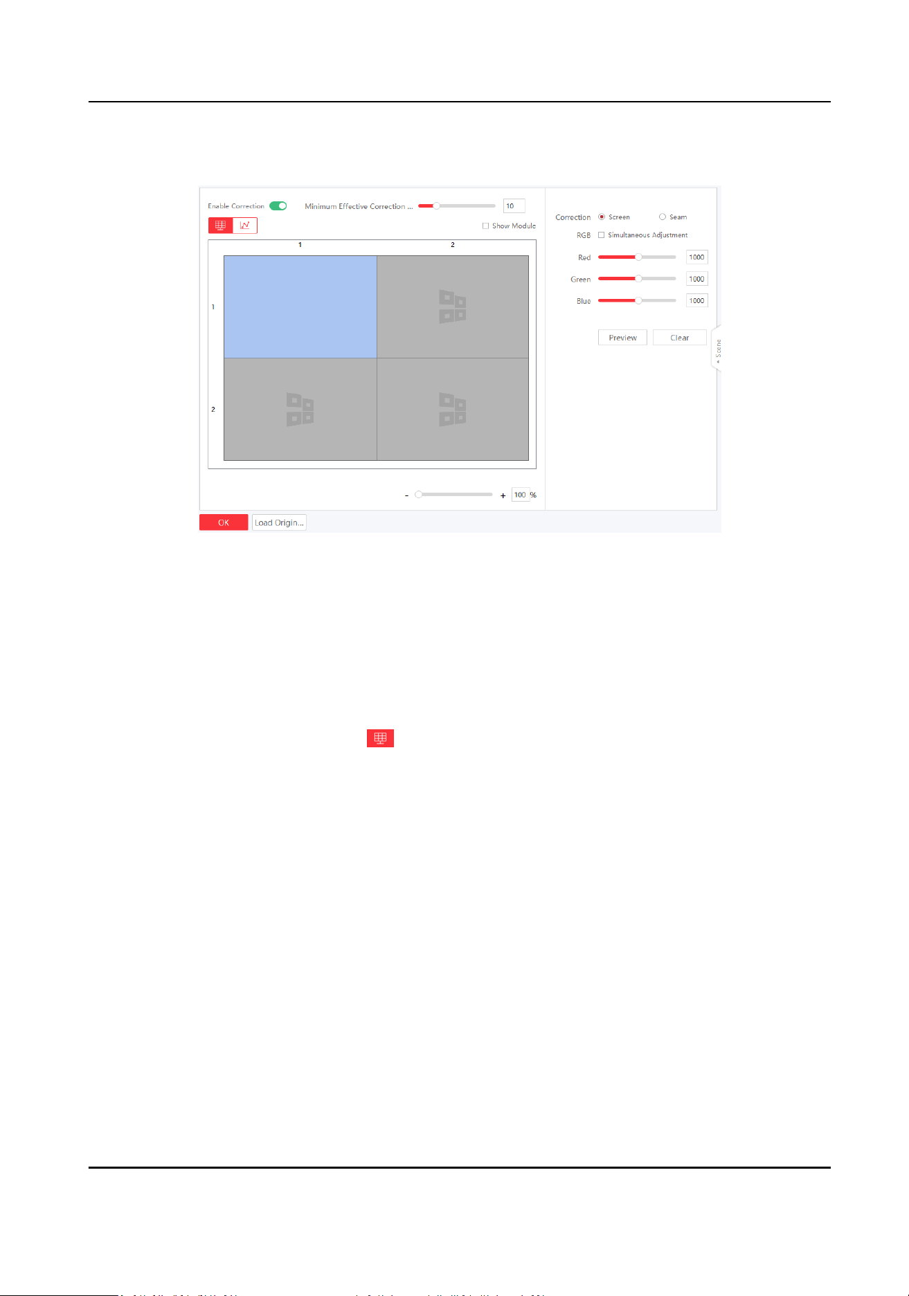
5. Correct the whole screen or correct the selected area of the screen.
-
Correct the whole screen: click , and select the desired screen.
Full-Color LED Display Controller User Manual
11
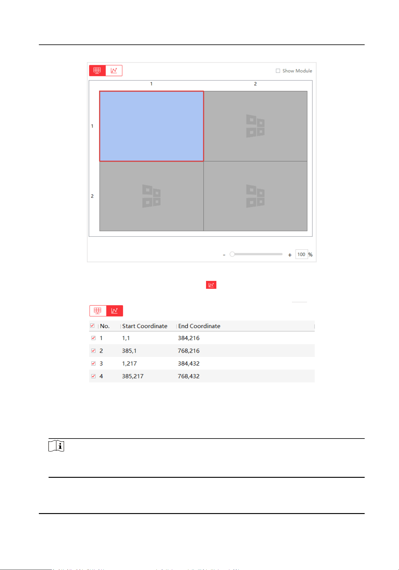
Figure 3-4 Correct the Whole Screen
-
Correct the selected area of the screen: click , and input the start coordinate and end
coordinate of the desired area.
Figure 3-5 Correct the Area of the Screen
6. Adjust RGB value.
-
Drag the bars.
-
Enter numbers in the text boxes.
Note
• You can check Simultaneous Adjustment to adjust RGB simultaneously.
• The number ranges from 800 to 1200, and the default value is 1000.
Full-Color LED Display Controller User Manual
12
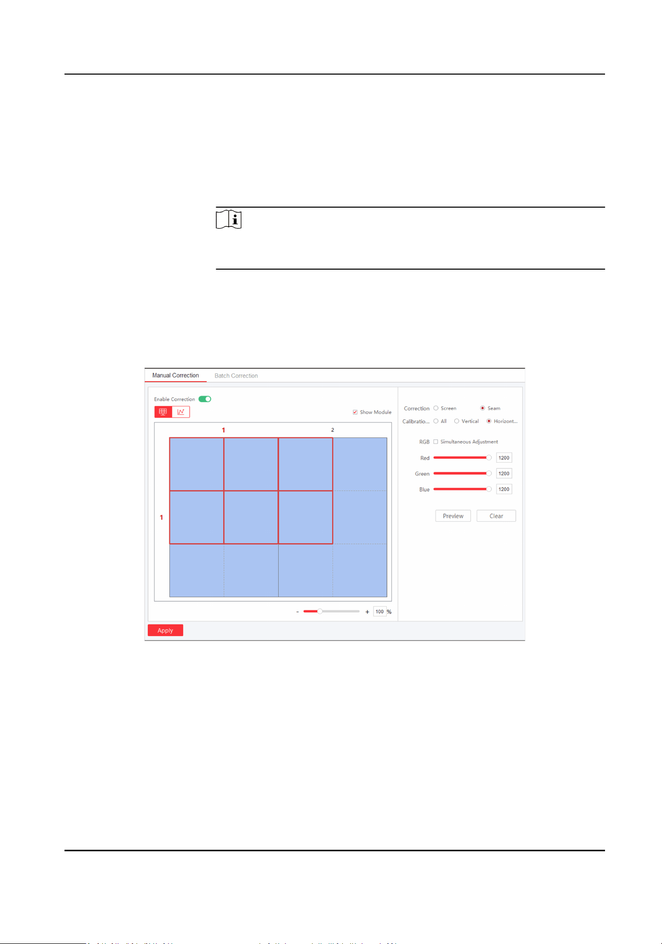
7. Click Preview or press Enter to check the
eects.
8. Click Apply.
Operaon Descripon
Clear Reset all parameters if needed.
Load Original Data Load original correcon data.
Note
The funcon may vary with models. The parameters will not be
displayed when the funcon not supported.
Correct Seam Manually
Steps
1. Click Screen Adjustment → Advanced Operaon → Correcon → Manual Correcon .
Figure 3-6 Correct Seam Manually
2. Select Enable Correcon.
3. Select Seam in Correcon.
4. Select Calibraon Range.
All
Correct all seams.
Vercal Line
Correct all vercal seams.
Full-Color LED Display Controller User Manual
13
Horizontal Line
Correct all horizontal seams.
5. Select area to correct.
-
Check Show Module and select the module to correct.
-
Uncheck Show Module and select the screen to correct.
6. Drag the bar to adjust Seam Width.
Note
The seam width ranges from 1 to 10.
7. Adjust RGB value.
-
Drag the bars.
-
Enter numbers in the text boxes.
Note
• You can check Simultaneous Adjustment to adjust RGB simultaneously.
• The number ranges from 800 to 1200, and the default value is 1000.
8. Click Preview to check the eects.
9. Click Apply.
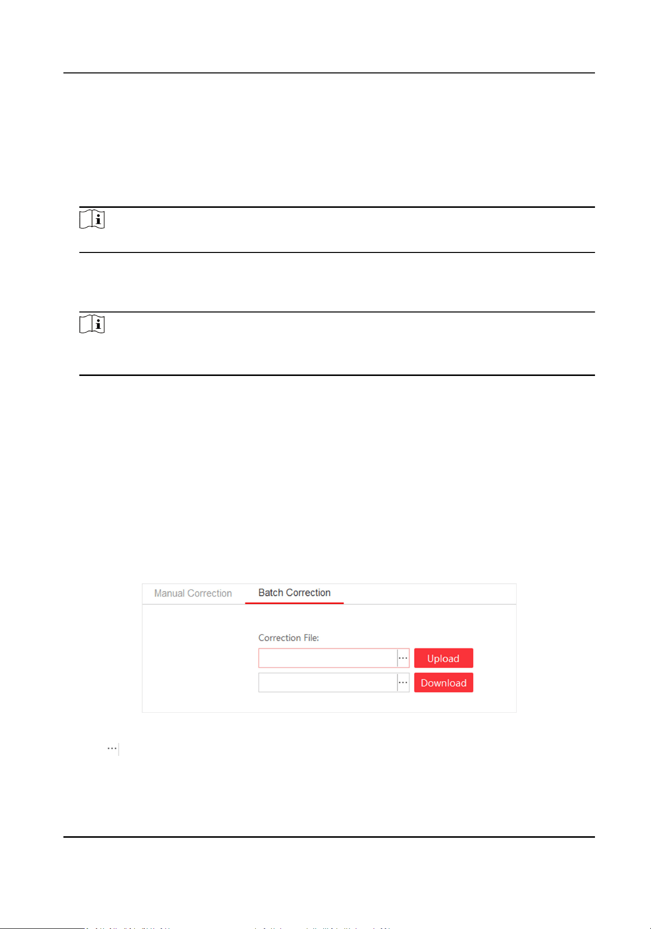
Batch Correct Screen
You can correct screen display in a batch by imporng correcon le.
Before You Start
• The correcon le has been obtained from the supplier.
• Select a screen as the start of the batch
correcon in the Manual Correcon .
Steps
1. Click Screen Adjustment → Advanced Operaon → Correcon → Batch Correcon .
Figure 3-7 Batch Correcon
2. Click to select correcon le.
3. Click Upload. The screens/seams will be corrected based on the uploaded le.
Operaon
Descripon
Full-Color LED Display Controller User Manual
14
DownLoad Download the correcon le as the backup les. You can also upload this
correcon le to correct other devices.
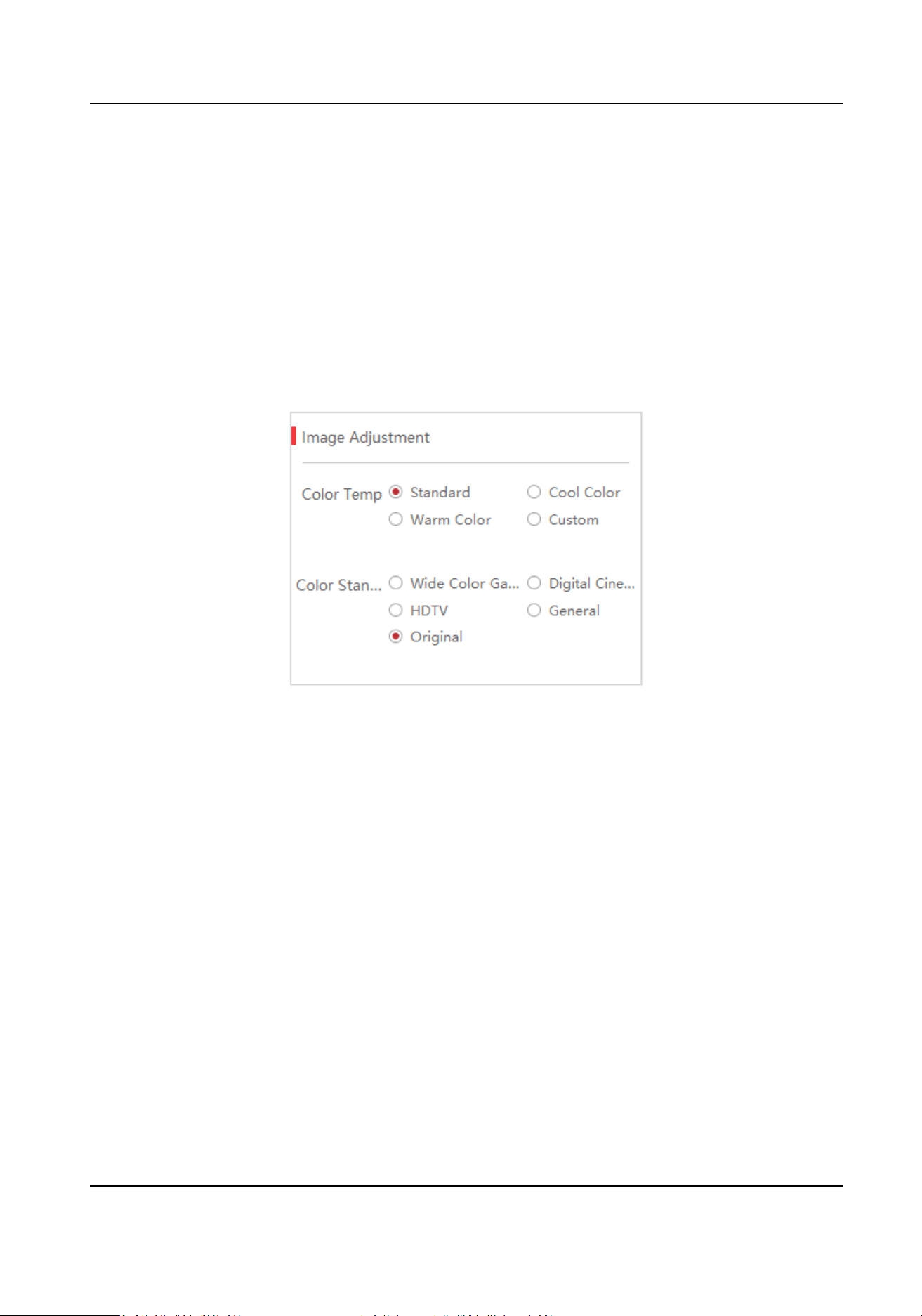
3.3.2 Congure Screen Color
You can adjust color temperature and color standard as needed.
Before You Start
Connect the signal source to the device before conguring the image contrast and saturaon.
Steps
1. Go to Screen Adjustment → Basic Control → Image Adjustment .
Figure 3-8 Image Adjustment
2. Select Color Temperature .
3. Select Color Standard.
Wide Color Gamut
Applicable to UHD (Ultra High
Denion) devices.
Digital Cinema
Applicable to digital cinemas and high-end displays.
HDTV
Applicable to HDTV(High Denion Television) and other common video devices.
General
Applicable to general displays.
Original
Restore to the original color.
Full-Color LED Display Controller User Manual
15
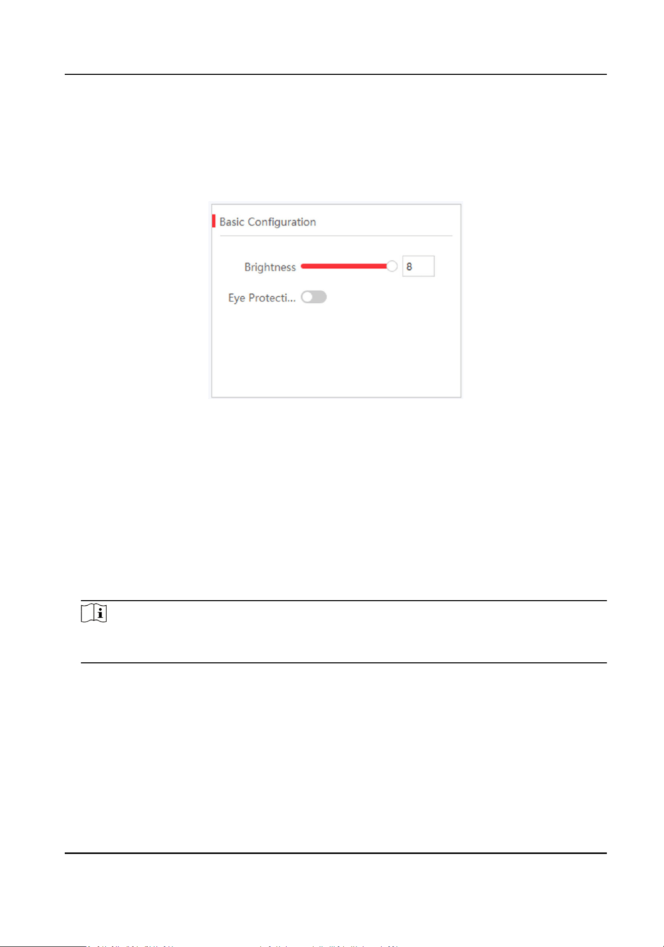
3.3.3 Congure Brightness
Congure LED screen brightness.
Steps
1. Click Screen Adjustment → Basic Control → Basic
Conguraon .
Figure 3-9 Brightness Adjustment
2. Adjust the brightness. Brightness ranges from 1 to 8. Brightness of energy saving mode ranges
from 1 to 2. Brightness of balanced mode ranges from 3 to 4. Brightness of high light mode
ranges from 5 to 6. Brightness of sport mode is from 7 to 8.
-
Slide the slider.
-
Enter numbers in the text box.
Brightness
Brightness is a photometric measure of the luminous intensity per unit area of light traveling
in a given
direcon. It describes the amount of light that passes through, is emied or
reected from a parcular area, and falls within a given solid angle. The SI unit for luminance
is candela per square metre (cd/m2).
Note
If the device has congured mul-funconal card, you can check Auto to enable auto brightness
adjustment.
3. Enable Eye Protecon Mode as needed.
3.3.4
Congure Image Enhancement
You can enhance image display eects by client.
Before You Start
Connect the signal resource to the device correctly.
Full-Color LED Display Controller User Manual
16
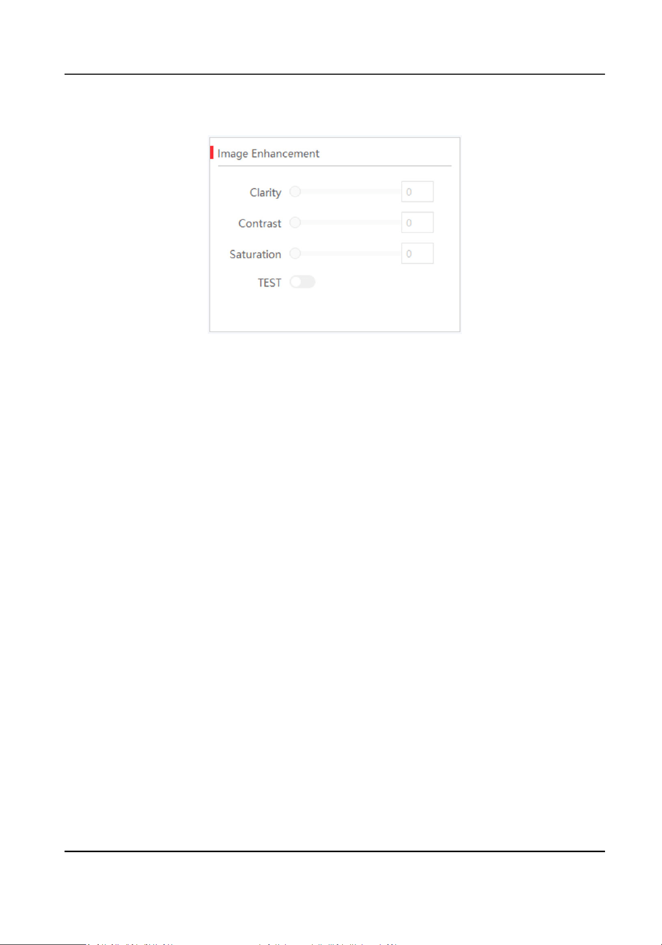
Steps
1. Go to Screen Adjustment → Basic Control → Image Enhancement .
Figure 3-10 Image Enhancement
2. Select Scene Enhancement or slide the slider to adjust Clarity, Contrast and Saturaon.
Sunlight Scene
When the device is in well-lit environment, you can select it and the corresponding strength.
Darkness Scene
When the device is not in well-lit environment, you can select it and the corresponding
strength.
3.
Oponal: Check Test to view the image eect on the screen. Screen on the le side shows the
image before enhancement, while the screen on the right side shows the image aer
enhancement.
3.3.5 Input Capability
You can enable 4K signal input, 3D video processing, input signal auto detecon, and resoluon
self-adapon,
and select input format as needed.
Steps
1. Click Screen Management → Advanced Operaon → Input Capability .
2. Set parameters as needed.
4K Signal Input
If you disable 4K signal input, we recommend you using 1080p signal input.
3D Video Processing
Check Enable when there is need for 3D video processing.
Full-Color LED Display Controller User Manual
17
Note
• Before enabling 3D Video Processing, you need to install
mulch-funconal card rst.
• Only when 3D parameters are congured into screens, 3D Video Processing can be
enabled.
•
Aer enable 3D Video Processing, 3D Processing Mode and Le-Right Image Switch can
be supported.
3D Processing Mode
3D Processing Mode is divided into
Le-Right Alternang, Le-Right Image Integraon and
Upper-Lower Image Integraon.
• When you select Le-Right Image Integraon or Upper-Lower Image Integraon, the
frame rate for signal source input is 120 Hz, the video needs to be set to
Le-Right Image
Integraon or Upper-Lower Image Integraon and the signal source output method needs
to be set to
shuer acve switching mode.
• When you select Le-Right Alternang, the frame rate for signal source input is 60 Hz, the
video is played in the full screen and there is no need for other operaons.
Le-Right Image Switching
When the le image is opposite to the right image, you can enable Le-Right Image
Switching.
Input Signal Auto Detecon
Check Enable to detect input signal automacally.
Best Resoluon Self-Adapon
Check Enable, and the input and output resoluon will be the same automacally.
Input Format Support
The input standard is RGB by default. Select Auto Recognion when the signal standard is
not RGB.
Note
Before enabling 3D funcon, you need to install mulch-funconal card rst.
3. Click OK.
3.4 Volume Adjustment
You can adjust the audio input volume of LED display on the client.
Before You Start
The Input Capability is enabled in Screen Management → Advanced Operaon → Input
Capability .
Full-Color LED Display Controller User Manual
18
Steps
1. Go to Screen Adjustment → Basic Control → Basic
Conguraon .
2. Slide the slider or enter numbers in the text box to adjust the volume.
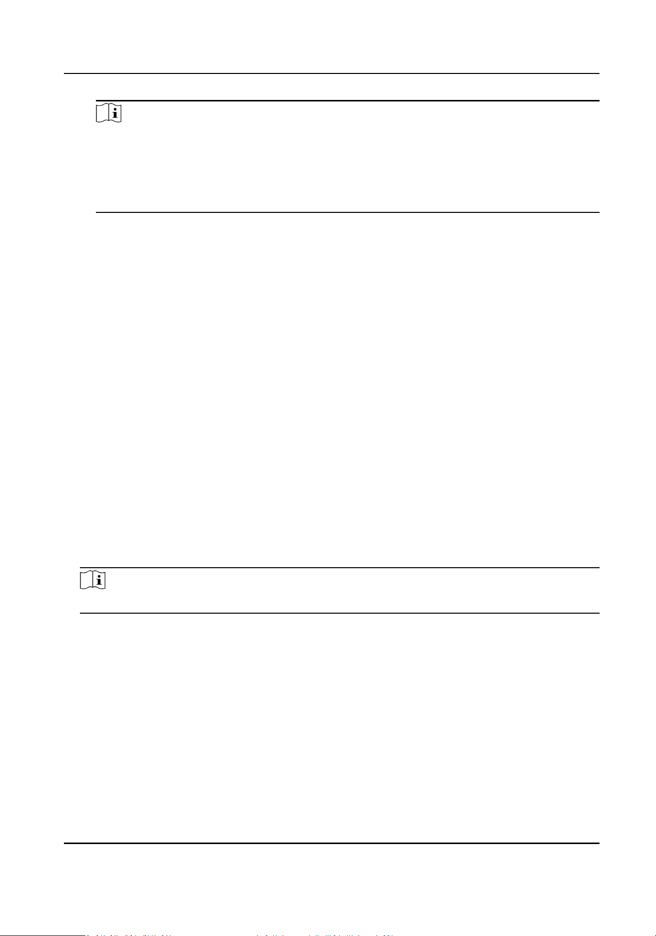
3.5 Congure a Scene
You can save the conguraons of, for example, signal input type, 3D video processing, or video
opening window, as a scene to call for convenience.
Steps
1. Click Scene on the right of the interface.
Figure 3-12 Scene Conguraon
2. Click .
3. Enter a scene name.
4. Click Finish to save the scene into the scene list.
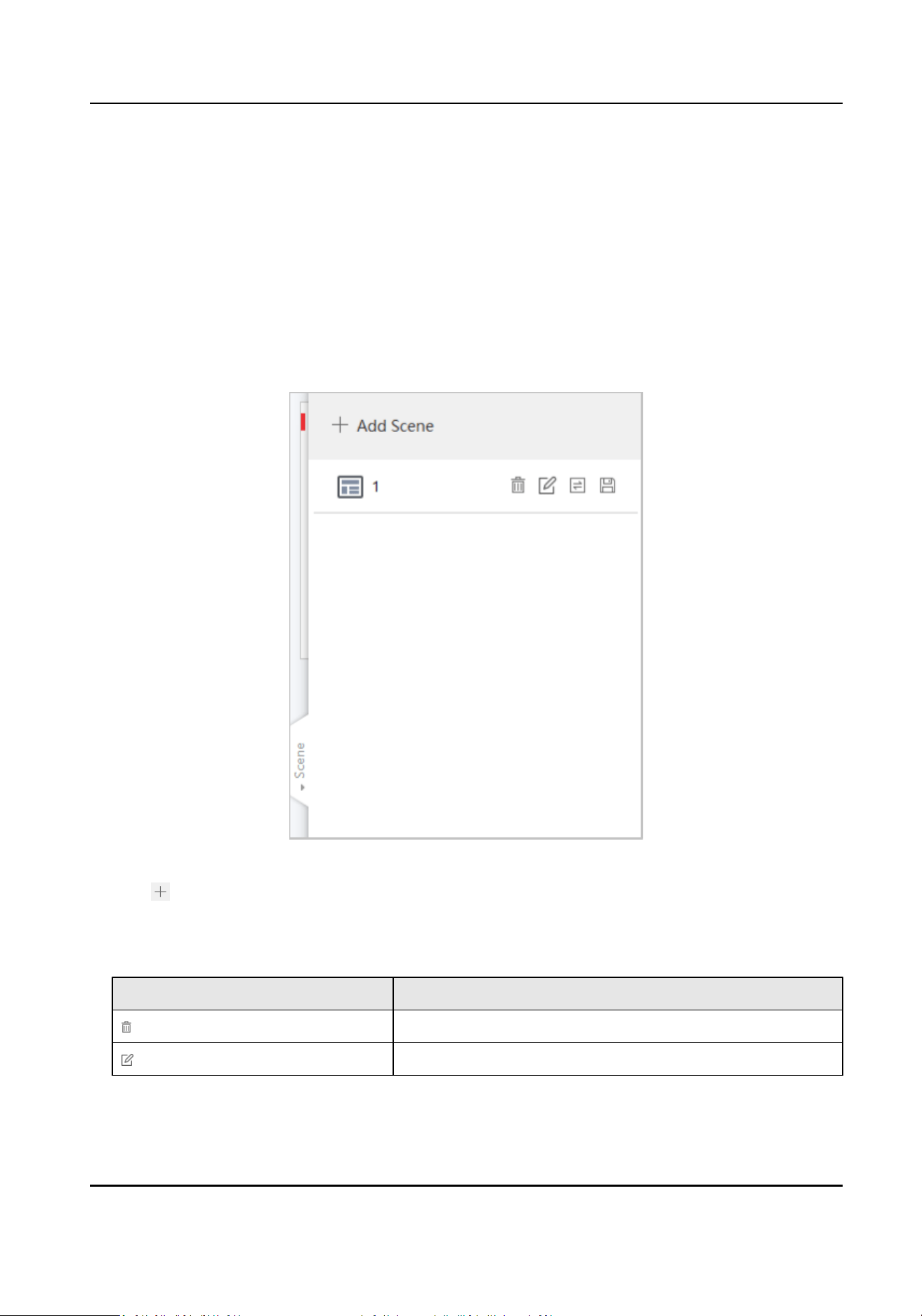
5.
Oponal: You can also do the following operaons.
Operaon
Descripon
Delete the scene.
Edit the scene name.
Full-Color LED Display Controller User Manual
19
Operaon Descripon
Call the scene.
Apply the scene.
3.6 Add Device Alias
Device alias is used to disnguish devices from each other.
Steps
1. Click on the Display Status.
2. Edit device alias.
3. Click OK to save the device alias.
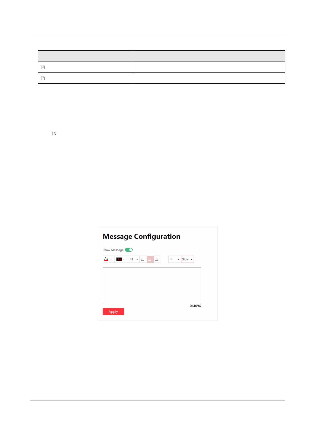
3.7
Congure Message
Release rolling/stac meaasge to terminal by the client.
Before You Start
No-signal screensaver is in custom mode. Refer to Congure No-Signal Screensaver .
Steps
1. Click Screen Adjustment → Advanced Operaon → Message Conguraon .
Figure 3-13 Message Conguraon
2. Enable Show Message.
3. Enter message in the text box.
4.
Congure text style, including font color, font size, posion and rolling speed.
Full-Color LED Display Controller User Manual
20
Note
Background color is black by default and is not adjustable.
5. Click Apply.
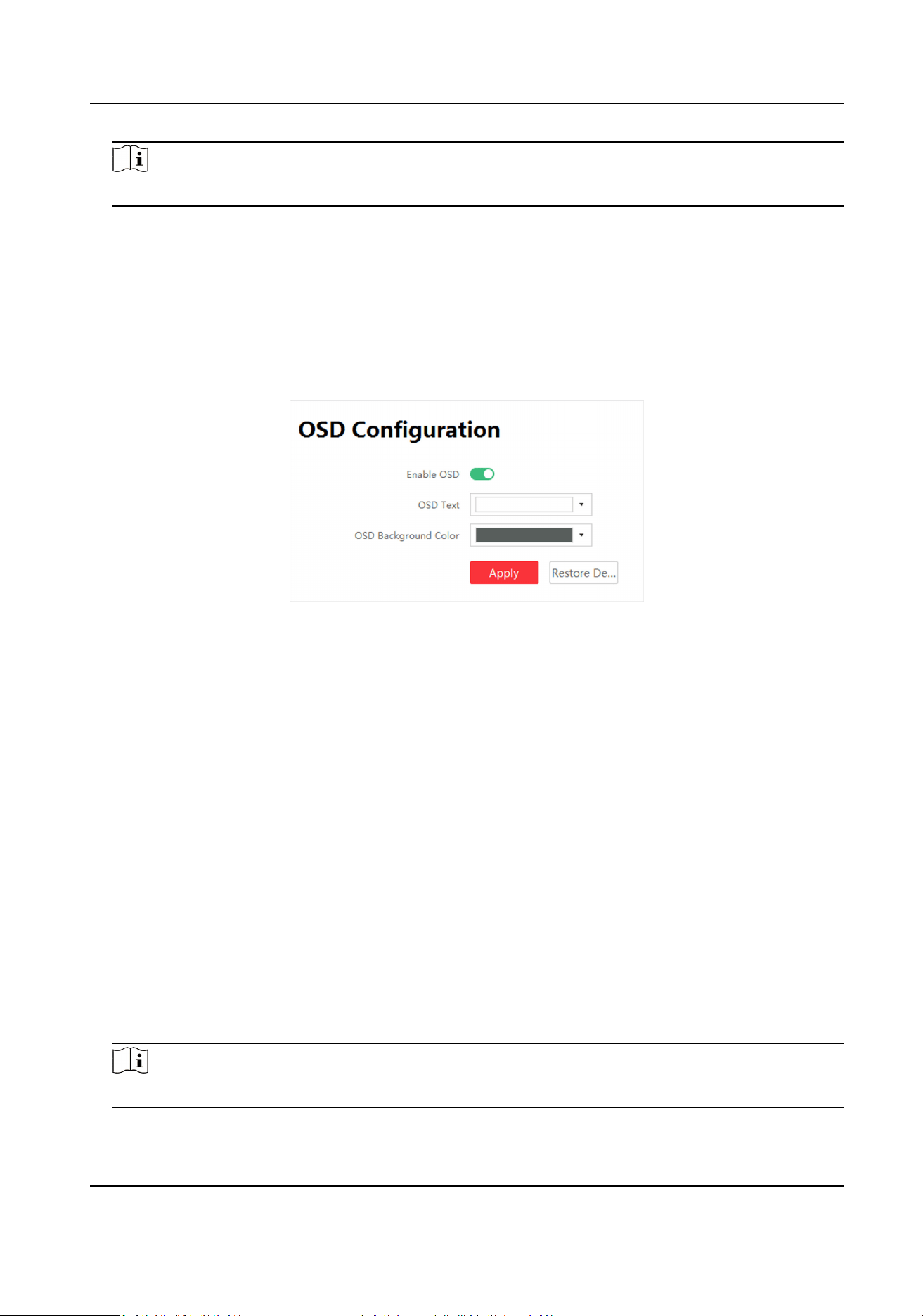
3.8 Congure OSD
Screen will display prompts aer conguring OSD (On-screen Display).
Steps
1. Click Screen Adjustment → Advanced Operaon → OSD Conguraon .
Figure 3-14 OSD Conguraon
2. Click Enable OSD.
3. Congure OSD Text and OSD Background Color.
4. Click Apply.
Operaon
Conguraon
Restore Default Sengs Restore to default OSD sengs.
3.9 Congure Network
The device will obtain IP automacally when the network segment of the device has changed.
Before You Start
The network segment connected by the device has DHCP (Dynamic Host Conguraon Protocol)
funcon.
Steps
1. Click Screen Adjustment → Advanced Operaon → Network Conguraon .
2. Click Obtain IP Address
Automacally.
Note
This funcon is enabled by default.
Full-Color LED Display Controller User Manual
21
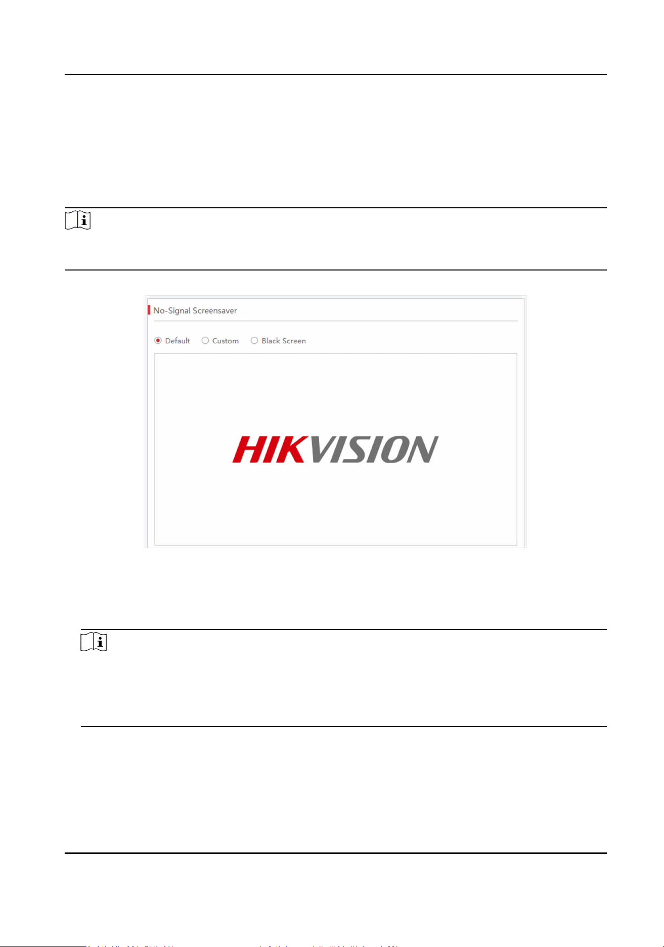
3.10 Congure No-Signal Screensaver
The screen will display default no-signal screensaver when there is week input signal or no input
signal.
Steps
Note
You can choose default mode, custom mode, and black screen mode. Here we take custom mode
as an example.
1. Click Screen Adjustment → Basic Control → No-Signal Screensaver .
Figure 3-15 No-Signal Screensaver Conguraon
2. Click Custom.
3. Click Select Picture to select the pictures.
4. Click Upload.
Note
• The picture format only can be JPG and
resoluon should be between 320 * 240 and 3840 *
3840.
• If you upload more than one picture, the pictures will be auto switches automacally when
the screensaver displays.
5. Oponal: Check Random Play.
6. Oponal: select Picture Auto-Switch Interval.
System will auto-switch pictures randomly according to the interval when there is no input
signal.
Full-Color LED Display Controller User Manual
22
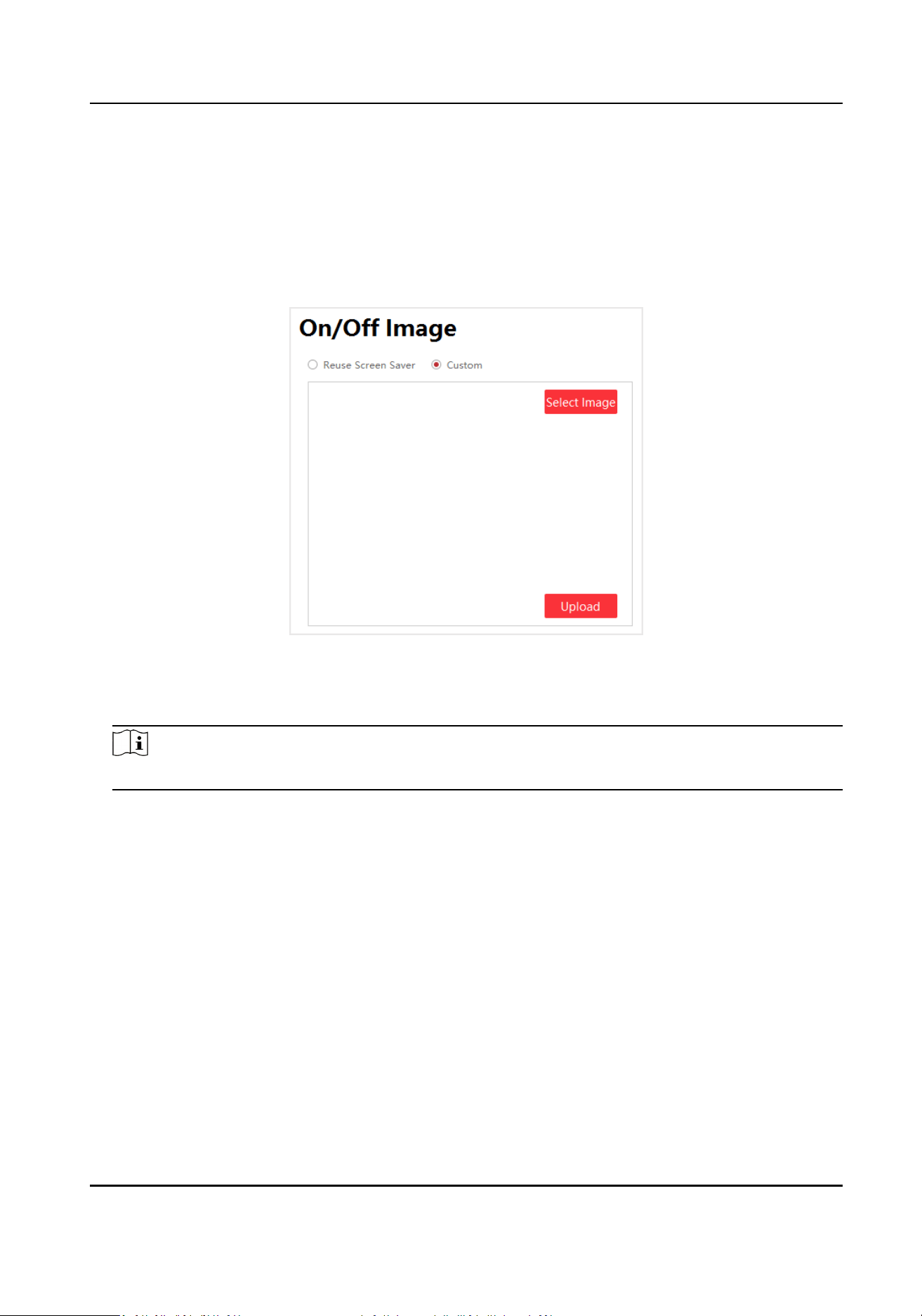
3.11 Congure On/o Image
You can use the screen saver as the on/o image or customize the image. Take customizing the
on/o image as an example.
Steps
1. Click Screen Adjustment → Advanced
Operaon → On/O Image .
Figure 3-16 On/O Image Conguraon
2. Click Custom, and click Select Image to select an image in your computer.
3. Click Upload.
Note
Only images in JPG format with resoluon from 320 × 240 to 3840 × 3840 are available.
3.12 Congure Mulcast Control
Through mulcast funcon, you can control and congure several devices simultaneously.
Steps
Mulcast
In computer networking, mulcast is group communicaon where informaon is addressed to a
group of
desnaon computers simultaneously. Mulcast can be one-to-many distribuon.
1. Click Screen Adjustment → Advanced Operaon → Mulcast Control .
2. Check Enable
Mulcast.
Full-Color LED Display Controller User Manual
23
Note
Items available for mulcast control include brightness/white balance, signal input switch,
dehumidicaon conguraon, aribute conguraon, system conguraon, basic
conguraon, and advanced conguraon. Check the items based on your needs.
3. Check the device you want to synchronize.
4. Click OK.
Note
You can login to any checked IP to achieve mulcast control.
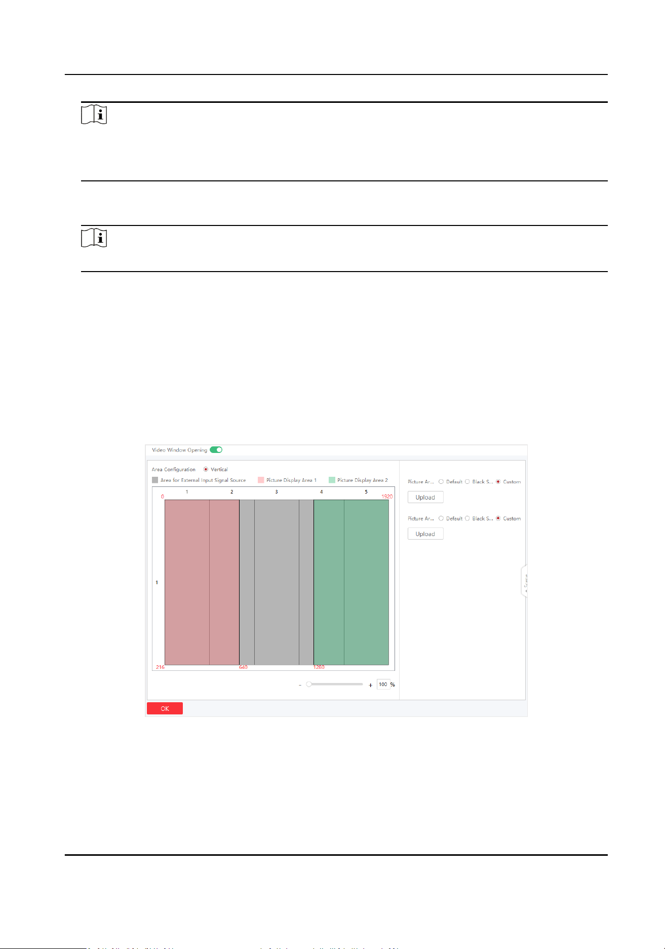
3.13 Congure Video Window Opening
Video opening window is a virtual split screen on the LED display to meet the combined display of
mulple contents. Currently, the enre screen can be divided into three areas: le, center, and
right. The
le and right areas are picture areas, and the center area is the input area of external
signal sources.
Steps
1. Click Screen Adjustment → Advanced Operaon → Video Window Opening .
Figure 3-17 Video Window Opening Conguraon
2. Enable Video Window Opening. The screen is divided into le, center, and right areas vercally
by default.
3.
Oponal: Adjust the split screen layout by dragging the vercal line of the center area.
4. Congure the pictures to be displayed in the le and right areas in the upper-right corner.
Full-Color LED Display Controller User Manual
24
Default
The area displays the defalut picture in the system.
Black Screen
The area displays black screen.
Custom
Click Upload to upload pictures to be displayed. You can also replace or delete the uploaded
pictures.
Please upload pictures in JPEG or JPG format with size smaller than 6 MB.
5. Click OK.
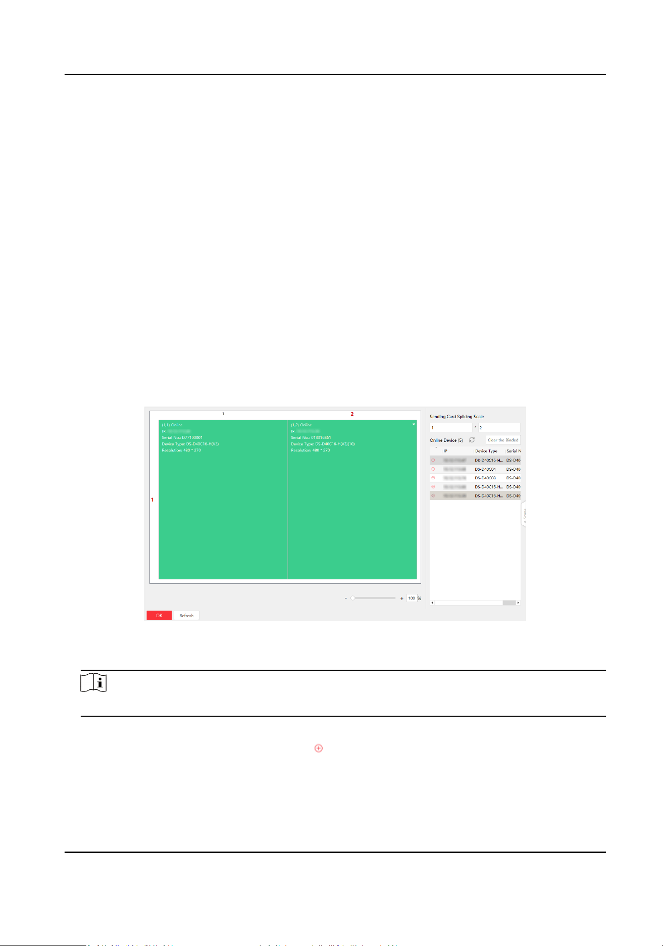
3.14
Congure Screen Splicing
You can splice mulple LED screens into one to display a complete picture, without the need for
processing by professional video wall controllers. 3D screen splicing is available.
Steps
1. Click Screen Splicing Conguraon.
Figure 3-18 Screen Splicing Conguraon
2. Congure the sending card splicing scale.
Note
Up to 4 × 4 are available for the splicing scale.
3. Bind devices to the specic display areas. You can use one of the following ways.
-
Click to choose the area, and then click
before the desired device to bind.
-
Drag the desired device to the area to bind.
Full-Color LED Display Controller User Manual
25

Note
• Only horizontally screen splicing is supported.
• Please enter the user name and password for the
rst me login of the device.
• If you want to splice a new device, click
before the binded device rst, and then click
before the desired device.
• If the binded device is
oine, the splicing area will turns grey.
4. Click OK.
5.
Oponal: You can click Clear the Binded to clear all the binded devices.
Full-Color LED Display Controller User Manual
26
Chapter 4 Device Maintenance
4.1 Screen Defecve Pixel Detecon
You can check the defecve pixels of the screen.
You can hover over the virtual screen on Display Status to check the number of defecve pixels on
the screen.
Table 4-1 Defecve Pixel Detecon
Icon Descripon
Show the posion of defecve pixels on the display.
Show the coordinates of the defecve pixels on the client.
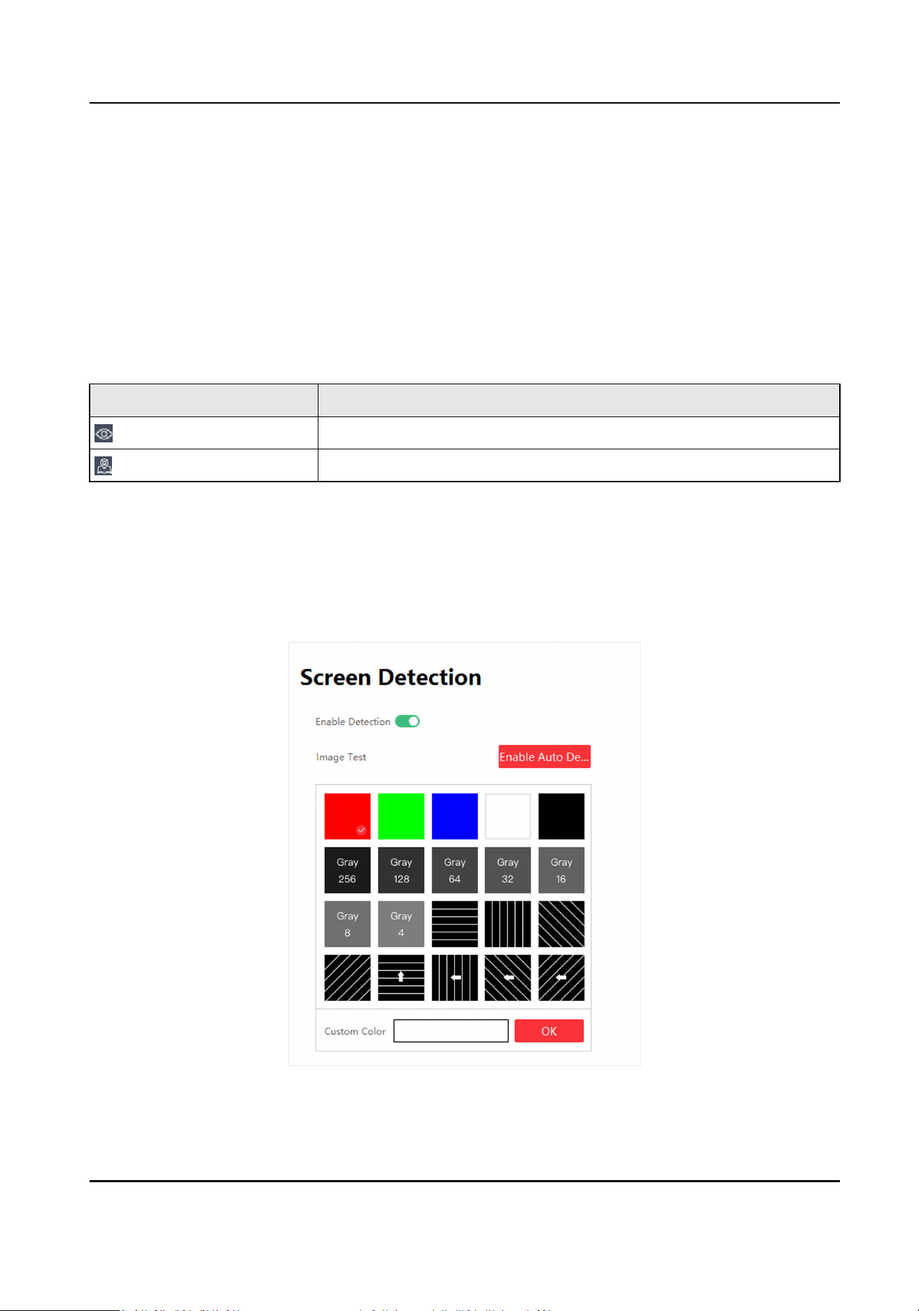
4.2 Test Screen Color
You can select dierent images to test if the LED screen can display normally.
Steps
1. Click Screen Adjustment → Advanced Operaon → Screen Detecon .
Figure 4-1 Screen Detecon
Full-Color LED Display Controller User Manual
27
2. Select Enable
Detecon.
3. Select the image you want to test.
-
Click the image you want to test.
-
Click the white box beside Custom Color to customize colors, and click OK.
-
Click Enable Auto
Detecon, and the system will display default images to test.
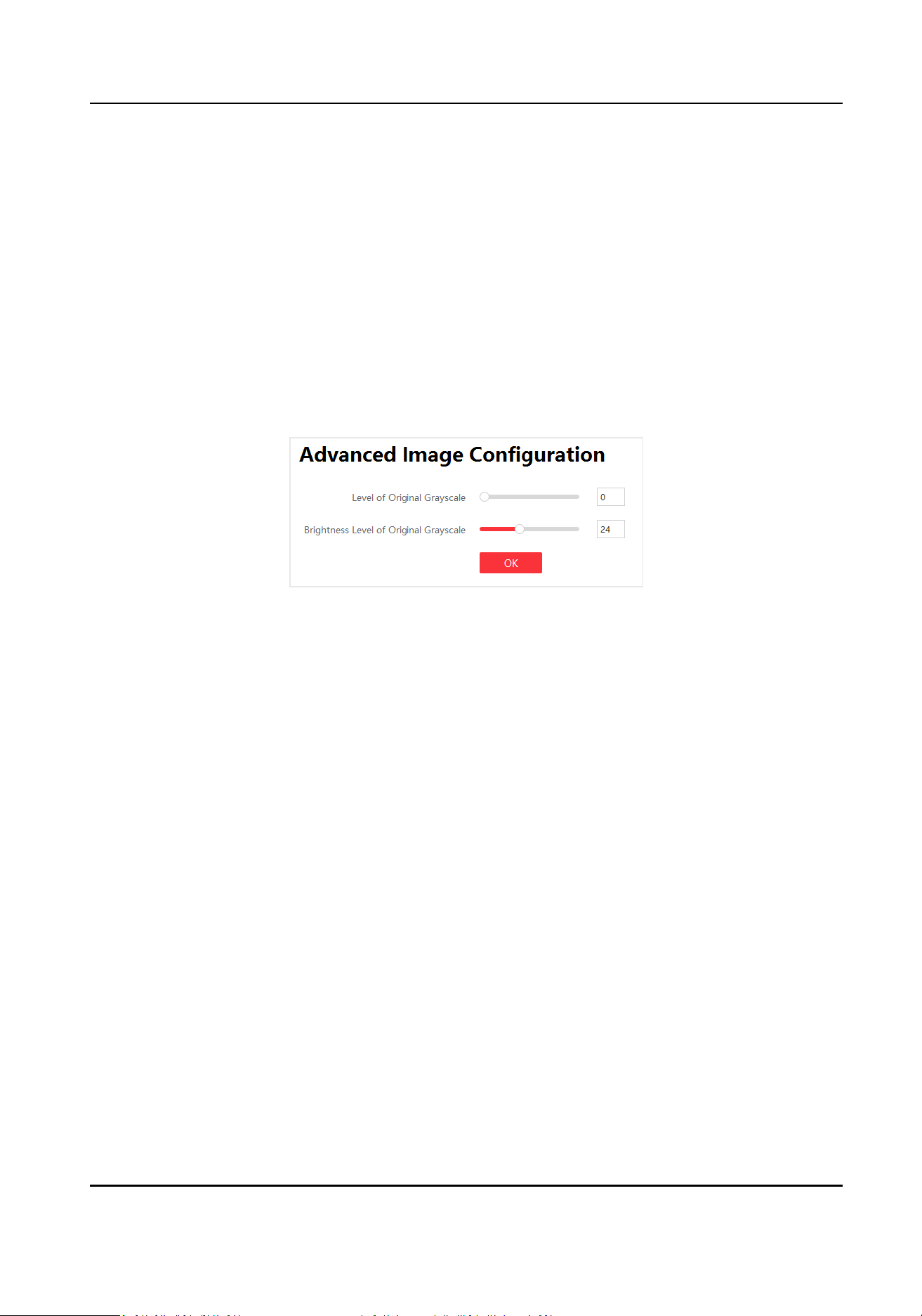
4.3 Congure Advanced Image
You can congure the level and brightness level of the original grayscale to improve the image
quality.
Steps
1. Click Screen Adjustment → Advanced
Operaon → Advanced Image Conguraon .
Figure 4-2 Advanced Image Conguraon
2. Drag the bar to congure the level.
Level of Original Grayscale
The higher the level is, the more colorful the LED screen displays and the higher the image
quality is.
Brightness Level of Original Grayscale
The higher the level is, the brighter the LED screen displays.
3. Click OK.
4.4
Congure Dehumidicaon
Dehumidicaon funcon is to avoid potenal LED screen damage caused by humid environment.
Steps
1. Click Screen Adjustment → Advanced Operaon → Dehumidicaon Conguraon .
Full-Color LED Display Controller User Manual
28
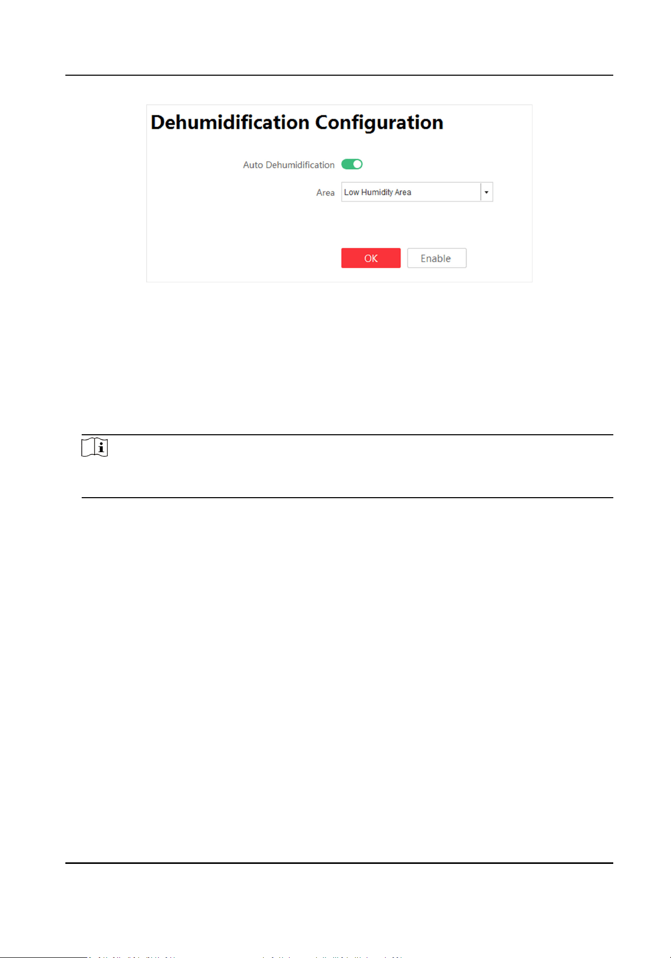
Figure 4-3 Dehumidicaon Conguraon
2. Select Auto Dehumidicaon.
3. Select Area. High Humidity Area, Medium Humidity Area, Low Humidity Area are selectable.
4. Click OK.
Operaon Descripon
Enable Dehumidicaon Enable dehumidicaon manually.
Disable Dehumidicaon Disable dehumidicaon manually.
Note
Disable dehumidicaon manually is valid for single me. Dehumidicaon funcon will be
auto enabled aer next startup.
4.5 Congure Work Mode
You can congure the Work Mode in the upper-right corner on the Display Status interface.
Congure the work mode according to dierent scenes to get high system performance.
Four kinds of work modes are available: Normal Mode, High-Performance Mode, Energy-Saving
Mode and HDR Mode.
Normal Mode
The brightness is level 3 by default and level 6 at most. Normal contrast. Original grayscale is level
0. Low refresh rate.
High-Performance Mode
The brightness is level 7 by default and level 10 at most. High contrast. Original grayscale is level 1.
High refresh rate.
Full-Color LED Display Controller User Manual
29
Energy-Saving Mode
The brightness is level 3 by default and level 3 at most. Normal contrast. Original grayscale is level
0. Low refresh rate.
HDR Mode
The brightness is level 10 by default and level 10 at most. High contrast. Original grayscale is level
1. High refresh rate.
Note
• The Normal Mode is recommended to prevent overheat caused by high
consumpon.
• When the system is restored to default or factory sengs, the work mode is Normal Mode by
default.
4.6 Detect Screen Status
Aer enabling screen status detecon, alarm informaon will be shown on the screen if the
temperature, voltage, number of defecve pixels of the screen and temperature of the sending
card exceeded the limit.
Steps
1. Select System
Sengs → System Detecon .
2. Set the limitaon of the screen voltage, screen temperature, seding card temperature and
number of
defecve pixels on the screen.
3. Click Apply.
4. Enable Screen Display.
4.7 View Device
Informaon
Check client version informaon and ocial website.
Select System
Sengs → About to check client version informaon and ocial website.
Select Display Status to check device version informaon, including Controller Version, FPGA
Version, Card Type, and so on.
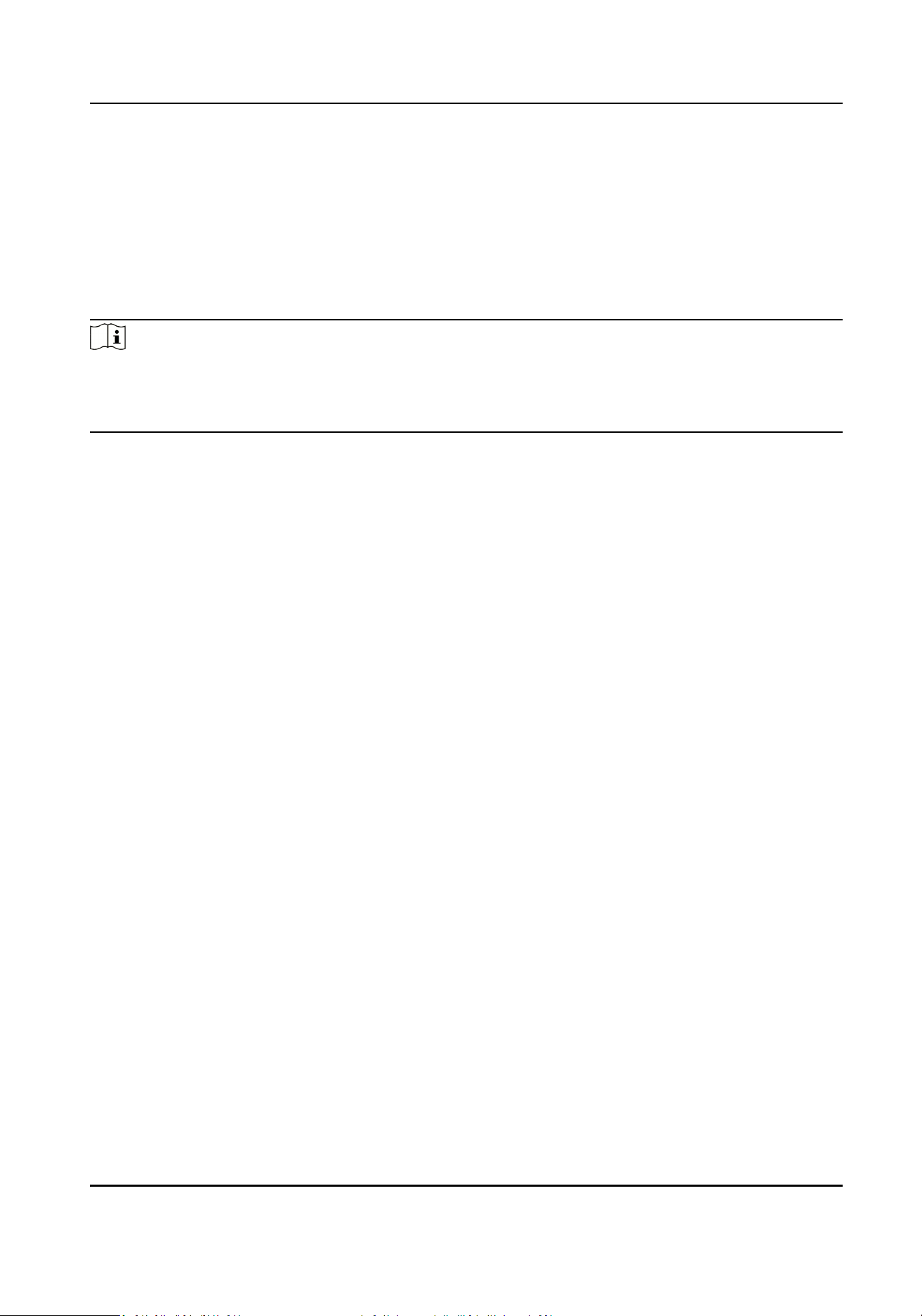
4.8 View Receiving Card
Informaon
View receiving card informaon, including network interface, number of connected devices,
whether the version is matched, and version number.
Steps
1. Select Display Status → Card Version .
Full-Color LED Display Controller User Manual
30
Figure 4-4 Receiving Card Version
2. Check receiving card details in the receiving card version interface for device maintenance.
3. Click OK.
4.9 Upgrade
Please use the latest rmware to obtain all possible security updates.
Note
Do not disconnect the power supply during updang.
4.9.1 Local Upgrade
Upgrade Receiving Card/Mul-funconal Card
You can upload upgrade patch to upgrade receiving card or mul-funconal card.
Full-Color LED Display Controller User Manual
31
Steps
1. Click System
Sengs → System Maintenance → Upgrade
2. Click
to select upgrade patch.
3. Click Upgrade.
Operaon Descripon
Auto Update Receiving
Card Version When
Reboong
When sending card reboots, it will detect receiving card
version. System will update receiving card version by default if
there is a new version.
Note
If upgrading failed and the device cannot funcon correctly, please contact suppliers in me.
Result
The device will reboot automacally when upgrade nished.
Upgrade Sending Card
You can upload upgrade le to upgrade receiving card or mul-funconal card.
Steps
1. Click System Sengs → System Maintenance → Upgrade
2. Click
to select upgrade patch.
3. Click Upgrade.
Note
If upgrading failed and the device cannot funcon, please contact suppliers in me.
Result
The device will reboot
automacally when upgrade nished.
4.9.2 Online Upgrade
Upgrade Receiving Card Online
Get the newest version of the upgrade package from the cloud to upgrade the receiving card.
Before You Start
The PC has been connected to the Internet.
Steps
1. Click Display Status.
Full-Color LED Display Controller User Manual
32
2. Click
on the right side of Receiving Card Version, the device will automacally get the newest
version of the upgrade package from the cloud.
Note
• If the receiving card is the newest version already, there is no need to upgrade.
• The receiving card will
automacally restart when upgraded.
Upgrade Sending Card Online
Get the newest version of the upgrade package from the cloud to upgrade the sending card.
Before You Start
The PC has been connected to the Internet.
Steps
1. Click Display Status.
2. Click
on the right side of Controller Version, the device will automacally get the newest
version of the upgrade package from the cloud.
Note
• If the sending card is the newest version already, there is no need to upgrade.
• The sending card will
automacally restart when upgraded.
Full-Color LED Display Controller User Manual
33
Chapter 5 System Maintenance
This chapter mainly introduces imporng/exporng conguraon le, searching logs, restoring
parameters, restoring default
sengs, and me synchronizaon.
5.1 Import/Export Conguraon File
Conguraon le can be imported to congure the system easily.
Steps
1. Click System Sengs → System Maintenance → Import and Export .
2. Click
to select le path.
3. Click Import.
5.2 Export
Conguraon File
Conguraon le can be exported for local backup.
Steps
1. Click System Sengs → System Maintenance → Import and Export .
2. Click
to select le path.
3. Click Export.
Note
Exported conguraon le is encrypon mode to prevent informaon disclosure. For more
details, please contact us.
5.3 Search and Export Logs
System operaon logs can be searched and exported for backup.
Steps
1. Click System Sengs → Search Log .
2. Set search
condions, including Start Time and End Time.
3. Click Search.
Note
Up to 2000 search results can display. Please narrow down the search scope if there too many
search results.
The results will be displayed in list.
Full-Color LED Display Controller User Manual
34

4.
Oponal: Click Export to export all the search results.
Note
Logs can be exported in CSV or XML le format. A prompt window will pop up when the logs are
exported successfully.
5.4 Sync Time
Steps
1. Click System
Sengs → System Maintenance → Sync Time .
2. Set me synchronizaon mode.
-
Select Local Time to synchronize the device me with the client.
-
Click
, seng display me manually, and click OK.
3. Click Time Sync.
5.5 Remote Reboot
Both sending card and receiving card can be rebooted remotely.
Steps
1. Click System
Sengs → System Maintenance → Others .
2. Select Sending Card or Receiving Card in the Remote Reboot.
3. Click Reboot.
5.6 Restore Factory
Sengs
All sengs can be restored to factory by default.
Steps
1. Click System Sengs → System Maintenance → Others .
2. Click Restore Factory Sengs.
3. Click OK in the pop-up window.
5.7 Restore User Default
Sengs
All sengs can be restored to user default sengs by default.
Steps
1. Click System Sengs → System Maintenance → Others .
2. Click Restore Default Sengs.
3. Click OK in the pop-up window.
Full-Color LED Display Controller User Manual
35
Chapter 6 Local Conguraon and Operaon
Use a combinaon of mul-funconal card and remote control to operate the LED screen OSD
menu.
Ensure the device is connected and
acvated before using the remote control.
Press Menu buon to go to Local Operaon. You can congure the parameters of input, output,
image, system, sending card and receiving card in Local
Operaon .
6.1 Mul-funconal Card (Oponal)
The mul-funconal card has an infrared receiver and a light sensor. With a mul-funconal card
connected with a receiving card, you can control the device remotely.
Note
•
Mul-funconal card 2.0 also supports 3D funcon.
• You need to upgrade the sending card rst to enable the funcon. Refer to Upgrade Sending
Card Online for more details.
6.2 Remote Control Funcons
There are two kinds of remote controls. If the sending card is used together with a mul-funconal
card, you can use the aliated infrared remote control. If not, You can use the standard infrared
remote control. The Max. distance of remote control is 10 m. The Max. angle of remote control is
45°.
Table 6-1 Remote Control
Funcons
Key Descripon
Power Turn on/o the screen.
Source Switch the signal source.
Volume Adjust the volume.
Scene Select the scene.
Brightness Adjust the brightness.
Up/Down/Le/Right Select the menu.
Back Back to the previous menu.
OK OK
Menu Enter the menu.
Full-Color LED Display Controller User Manual
36
Key Descripon
Shortcut Press the shortcut key and press the number key to enable
funcon quickly. Press the back key to disable the funcon.
• 0: Enable 3D
funcon.
• 1: Enable
dehumidicaon.
• 2: Enable image enhancement.
• 3: Enable image
correcon.
• 4: Enable
auto-adapve resoluon.
• 5: Enable auto-switch screensaver.
•
6: Enable screen self-checking.
Help Help
ID Select the desired screen(s).
Note
ID key of the remote control would take eect only if the corresponding sending card model is DS-
D42C16.
Full-Color LED Display Controller User Manual
37

Chapter 7 FAQ
7.1 Full Screen is Unlit
Reason
• No power supply for screen or control device.
• No input signal.
• The controlling computer is sleeping or the graphics card sengs are incorrect.
• Incorrect receiving card conguraon.
Soluon
• Check if the computer is in sleep or screensaver mode. If yes, start the computer, go to Control
Panel → Power
Opons → Change Plan Sengs , and set the sleep me to Never; If not, check
the connecon of the DVI cable between computer and control card.
• Check the graphics card sengs.
• Check the connecon between receiving card and sending card, and the connecon between
receiving cards.
• Restore to default
sengs.
7.2 Image is Incomplete or in Wrong
Posion
Reason
• Incorrect screen conguraon le.
• Incorrect signal cable connecon.
• Incorrect screen size conguraon.
Soluon
• For incomplete image, check if the congured screen scale and the actual screen scale are the
same.
• For image in wrong
posion, check if the congured display posion and screen scale are the
same as the actual. If not, adjust the parameters based on the dierence unl they are the
same.
• Check if the signal cable
connecon and the receiving card connecon among screen cabinets
are the same.
• Check if the
congured sending card output resoluon and the actual receiving card input
resoluon are the same.
Full-Color LED Display Controller User Manual
38

7.3 Full-screen Image Flashes or Vibrates
Reason
• DVI output of graphics card or other device fails.
• Receiving card number loaded by single network interface is larger than its load capacity.
• Signal cable is too long.
Soluon
• Check system connecon to see if the DVI cable or the network cable is loose, if the signal cable
length exceeds the allowable transmission distance, etc.
• Reduce receiving card loading number of each network interface.
Congure signal cable again on
the client aer changing connecon mode.
• Check the resoluon conguraons of the graphics card, sending card, and video processor.
7.4 Spots/Strips Exist in Full-screen Image
Reason
Incorrect screen type conguraon.
Soluon
Check screen type conguraon.
7.5 Certain Unit Image Flashes or Has Spots
Reason
• Loose connecon of receiving card or HUB card.
• Incorrect receiving card program.
• Check the receiving card, HUB card, and data cable
connecon in the unit.
• Check if the receiving card program of the unit is correct, or if the receiving card
funcons well.
7.6 Certain Unit Screen is Unlit
Reason
• The power supply or the receiving card of the unit fails.
• The signal output of the pervious unit fails.
Full-Color LED Display Controller User Manual
39

Soluon
• Check if the power supply output of the unit is 5 VDC.
• Check if power supply indicator of the receiving card in the unit is solid red, or if the receiving
card is
operang normally.
• Check the receiving card, HUB card, and data cable
connecon in the unit.
• Check if the receiving card signal output of the previous unit is normal.
7.7 Certain Module or Row of Modules are Unlit in Unit
Reason
• The switching power output controlling the modules fails.
• The signal output controlling the modules fails.
Soluon
• Check if the power supply output of the modules is 5 VDC.
• Check the connecon of the data cable and the HUB card controlling the modules.
7.8 Screen Display Error When Smart
Sengs
Reason
Screen parameter is wrong.
Soluon
• Check if the resoluon of receiving card and output resoluon of graphics card is the same.
• Check if the smart
seng wizard parameter is correct.
7.9 Searching Online Device Fail
Reason
• The network cable of the sending card is not connected.
• Incorrect
soware installaon (the winp plugin is not installed or its version is incorrect).
Soluon
• Check network cable connecon.
• Reinstall the winp plugin, or update the winp plugin directly.
Full-Color LED Display Controller User Manual
40

UD18357B