Loading ...
Loading ...
Loading ...

18 C6647M (10/21)
Positioning the Camera
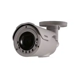
Figure 6. Camera Positioning
• Retaining Ring for Pan Adjustment (1): Loosen the set screw with the T20 I-key (supplied) and rotate the retaining ring to adjust the camera
horizontally until you are satisfied with the field of view.
• Bracket Axis for tilt Adjustment (2): Loosen the set screw with the T20 I-key (supplied) and tilt the bracket axis to adjust the camera
vertically u
ntil you are satisfied with the field of view.
• Adjustable Ring for 360º Rotation (3): Loosen the set screw with the T20 I-key (supplied) and rotate the camera body to adjust the camera
until you are satisfied with the field of view.
After adjustments, make sure to tighten each set screw with the T20 I-key to prevent the camera from moving.
NOTE: Limitation for three axes position:
• Pan range: 360º
• Rotate range: 360º
• Tilt range: +7.5º ~ -90º
NOTE: The camera field of view is set by making
adjustments to zoom and focus via the web UI. Refer to the operations manual.
Loading ...
Loading ...
Loading ...