3-YEAR WARRANTY
INSTRUCTION MANUAL
LUXPRO
®
PSPU732T
3 Heating and 2 Cooling with Automatic Humidity Control and Dual Fuel Switch
LUX Products Corporation
6000 Commerce Parkway, Suite-I • Mt. Laurel, NJ 08054
(856) 234-7905 • FAX (856) 234-7825
http://www.luxproproducts.com
52078

2 LUXPRO
®
PSPU732T
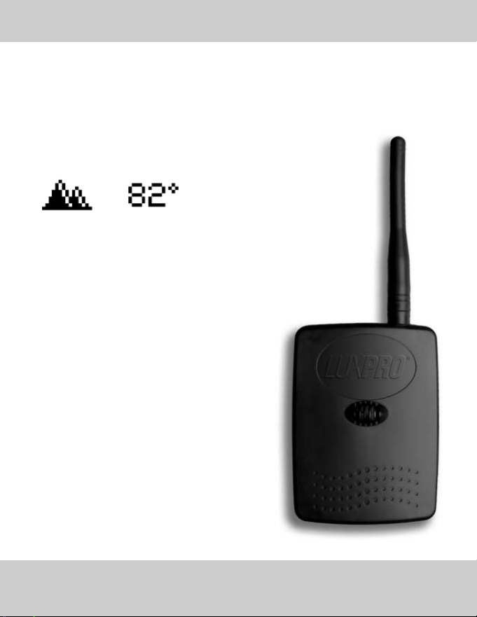
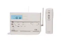
OOUUTTDDOOOORR WWIIRREELLEESSSS TTEEMMPPEERRAATTUURREE
TTRRAANNSSMMIITTTTEERR AANNDD RREECCEEIIVVEERR KKIITT
LUXPRO
®
Part No. WTR064
Outdoor Wireless Temperature
Transmitter and Receiver Kit Includes:
Transmitter
Antenna
Receiver Module
2 AA Batteries
U.S. Patent: 6,902,117
Accurately Displays
Current Outdoor Temperature
on the LUXPRO
®
Thermostat and
Enables Dual Fuel and
Automatic Humidity Capability
3INSTRUCTION MANUAL
LUXPRO
®
PSPU732T
Introducing the LUXPRO
®
PSPU732T touch-screen thermostat with 3-stage heating, 2-stage
cooling control, an automatic humidity controller and fossil fuel switch
(Available only when combined with LUXPRO
®
Outdoor Wireless Transmitter and Receiver
Kit. LUXPRO
®
Part No. WTR064)
• 7 Day programmable with 4 events per day
- including fan
• Large, easy to read dot matrix display
• True touch screen technology
• Automatic selection of cool or heat mode
• Programmable fan mode
• Programmable filter monitor
• Programmable installer message
• Configurable humidification relay
• Independent de-humidification relay
• Customizable full and partial
lock security
• Adjustable differential settings
for multistage installations
• Energy watch calculates kWh consumption
and real time HVAC cost
• Simple mode for non-programmable usage
• Programmable Vacation Mode
4

TABLE OF CONTENTS...................................................................................................................5
GLOSSARY OF TERMS..................................................................................................................6
SELECTING A LOCATION...............................................................................................................7
MOUNTING THE THERMOSTAT TO THE WALL ...............................................................................8
WIRING LEGEND...........................................................................................................................9
WIRING DIAGRAMS ....................................................................................................................10
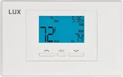
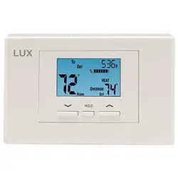
HOME SCREEN...........................................................................................................................16
CONTROL SCREEN.....................................................................................................................17
THERMOSTAT OPERATION MODES .............................................................................................18
TEMPERATURE CONTROL MODES ..............................................................................................19
AUTOMATIC HUMIDITY CONTROL ...............................................................................................20
HUMIDIFY AND HUMIDITY SETPOINT ..........................................................................................21
DE-HUMIDIFY AND HUMIDITY SETPOINT.....................................................................................22
FAN OPERATION MODES ............................................................................................................23
MENU SCREEN...........................................................................................................................24
DATE AND TIME SETTINGS .........................................................................................................26
PROGRAM SETTINGS .................................................................................................................27
ENERGY WATCH .........................................................................................................................28
SET SCREEN OPTIONS ...............................................................................................................29
VACATION MODE........................................................................................................................30
FILTER MONITOR........................................................................................................................31
ADVANCED SETTINGS - FEATURES SETTINGS ............................................................................32
ADVANCED SETTINGS - SYSTEM CONFIGURATION......................................................................34
ADVANCED SETTINGS - DUAL FUEL SWITCH ..............................................................................35
ADVANCED SETTINGS - DIFFERENTIAL SETTINGS ......................................................................36
ADVANCED SETTINGS - TIMER FEATURE ....................................................................................37
ADVANCED SETTINGS - HEAT PUMP ..........................................................................................38
ADVANCED SETTINGS - HUMIDITY SETTINGS .............................................................................39
ADVANCED SETTINGS - CALIBRATION ........................................................................................42
ADVANCED SETTINGS - CALIBRATION ........................................................................................43
SIMPLE THERMOSTAT MODE .....................................................................................................44
TROUBLESHOOTING...................................................................................................................45
IMPORTANT NOTICE ..................................................................................................................46
WARRANTY................................................................................................................................47
TABLE OF CONTENTS
5INSTRUCTION MANUAL

GLOSSARY OF TERMS
6 LUXPRO
®
PSPU732T
CYCLE RATE - Cycle rate is the frequency that heating or cooling equipment is turned on during a
certain period of time. Cycle rate is often given in units of cycles per hour (CPH).
DEHUMIDIFY - The process of removing moisture from the air.
DEHUMIDIFIER - Device used to remove moisture from the air.
DIFFERENTIAL - Differential is defined as the difference between the cut-in and cut-out points as
measured at the thermostat under specified operating conditions. For example, if the thermostat
turns the heating equipment on at 70 degrees F and turns the heating equipment off at 74 degrees
F, then the differential is 4 degrees F.
HUMIDIFIER - A device used to add moisture to a space.
HUMIDISTAT - A control which is operates the humidifier and is affected by changing humidity.
HUMIDITY - Moisture in the air.
PROGRAMMABLE THERMOSTAT - A thermostat with the capability of automatically adjusting tem-
perature set point to pre-selected settings at pre-selected times.
SETBACK - The automatic alteration of the thermostat control point(s) by means other than man-
ually changing the temperature set point.
SET POINT - The desired temperature setting on an electromechanical or electronic thermostat.
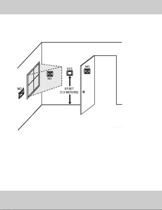
Install your LUXPRO
®
thermostat approximately 5 feet (1.5 meters) above the floor in an area
with good air circulation.
Avoid the following locations:
• Hot or cold air from ducts
• Radiant heat for appliances or sun such as a skylight
• Unheated or uncooled areas: for example an outside wall behind the thermostat.
• Ensure that there is no furniture directly below or beside the thermostat.
SELECTING A LOCATION
7INSTRUCTION MANUAL

MOUNTING THE THERMOSTAT TO THE WALL
8 LUXPRO
®
PSPU732T
1. Make sure to turn off the power supply located at the electrical service panel.
All heating and cooling units should be OFF.
2. Separate the backplate from the thermostat by grasping the unit firmly at the bottom lip and
pulling gently until the two piece are apart.
3. Align the backplate to the wall.
4. Mark the three locations for drilling the 3/16” holes required for the plastic screw anchors.
5. Remove the backplate and drill the three 3/16” holes in these locations.
6. Insert the plastic gyproc screws and ensure that they are snug in the wall.
7. Securely mount the backplate to the wall with the 3 supplied screws.
8. Make the appropriate wire connections based on the specifications of the
household HVAC unit(s). Please refer to Wiring Table to determine the appropriate wire connec-
tions.
9. Place the thermostat on the backplate by firmly but gently from the top aligning the pins with
the screw terminals.
10. Turn on the electricity at the electrical service panel.
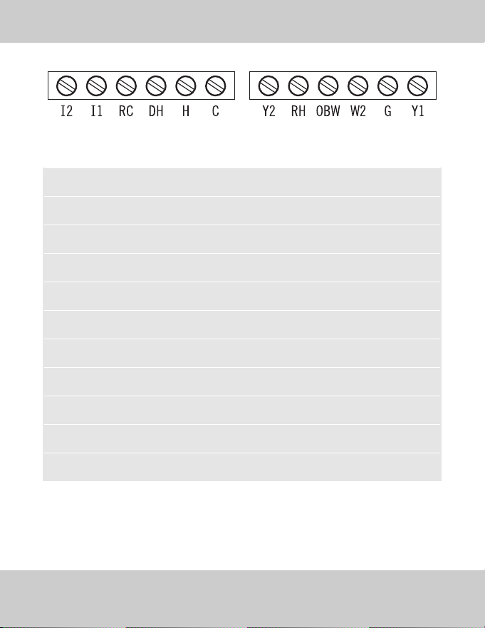
TERMINAL EQUIPMENT STANDARD COLOR
Y1 First Heat Pump and AC Yellow
G Fan Green
W2 First Stage Furnace White
OBW Reverse Valve - Second Stage Furnace Orange
RH 24v Red
Y2 Second Heat Pump and AC Unknown
C Common Blue
H Humidity Control Unknown
DH Dehumidify Control, Variable Fan Control Unknown
RC 24v Unknown
11 and 12 Not Used
NOTE: The above colors are standard in HVAC industry. The wiring should be confirmed
before installation
WIRING LEGEND
9INSTRUCTION MANUAL
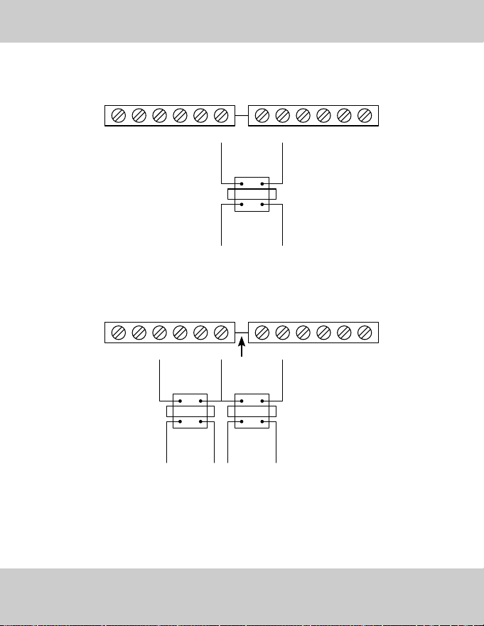
WIRING DIAGRAMS
10 LUXPRO
®
PSPU732T
I2
1 AIR CONDITIONER
24V
FAN
AC
I1 RC DH H C Y2 RH OBW W2 G Y1
COMMON
COOL 2
I2
2 STAGE COOL
24V
FAN
COOL 1
I1 RC DH H C Y2 RH OBW W2 G Y1
COMMON
HEAT 2
HEAT 1
I2
1 AIR CONDITIONER AND 2 STAGE HEAT
24V
FAN
AC
I1 RC DH H C Y2 RH OBW W2 G Y1
COMMON
HEAT
I2
1 AIR CONDITIONER AND 1 STAGE HEAT
24V
FAN
AC
I1 RC DH H C Y2 RH OBW W2 G Y1
COMMON
WIRING DIAGRAMS
11INSTRUCTION MANUAL
HEAT
REVERSE VALVES
I2
1 HEAT PUMP AND 1 STAGE HEAT
24V
FAN
HP
I1 RC DH H C Y2 RH OBW W2 G Y1
COMMON
REVERSE VAL VES
I2
1 HEAT PUMP
24V
FAN
HP
I1 RC DH H C Y2 RH OBW W2 G Y1
COMMON
WIRING DIAGRAMS
12 LUXPRO
®
PSPU732T
WIRING DIAGRAMS
13INSTRUCTION MANUAL
I2
COMMON
2 HEAT PUMPS
HP2
24V
REVERSE VAL VES
FAN
HP1
I1 RC DH H C Y2 RH OBW W2 G Y1
I2
COMMON
1 HEAT PUMP AND 2 STAGE HEAT
HEAT 2
24V
REVERSE VALVES
HEAT 1
FAN
HP
I1 RC DH H C Y2 RH OBW W2 G Y1
HEAT
TRANSFORMER
COOL
TRANSFORMER
I2
2 TRANSFORMERS
I1 RC DH H C Y2
CUT
RH OBW W2 G Y1
I2
1 TRANSFORMER
I1 RC DH H C Y2 RH OBW W2 G Y1
HEAT
TRANSFORMER
WIRING DIAGRAMS
14 LUXPRO
®
PSPU732T
WIRING DIAGRAMS
15INSTRUCTION MANUAL
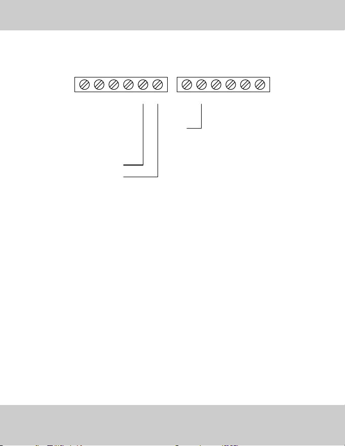
I2
HUMIDIFIER WITHOUT TRANSFORMER
24V
I1 RC DH H C Y2 RH OBW W2 G Y1
HUMIDIFIER 2nd WIRE
HUMIDIFIER 1st WIRE
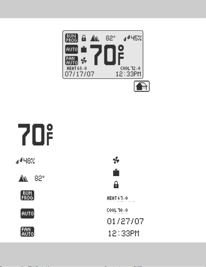
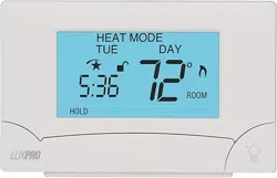
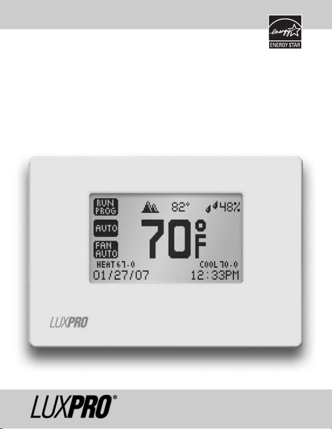
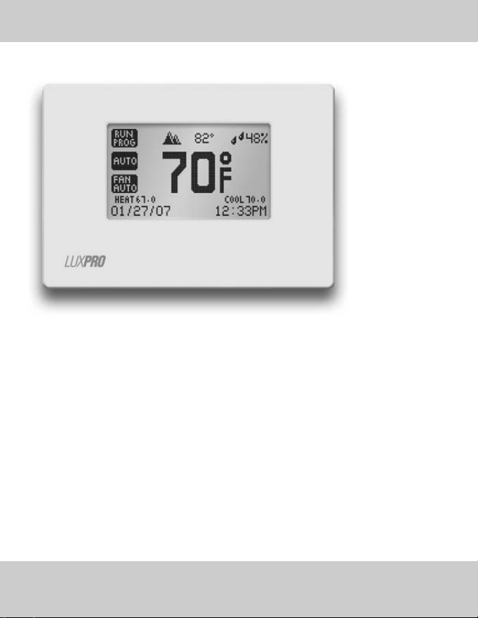
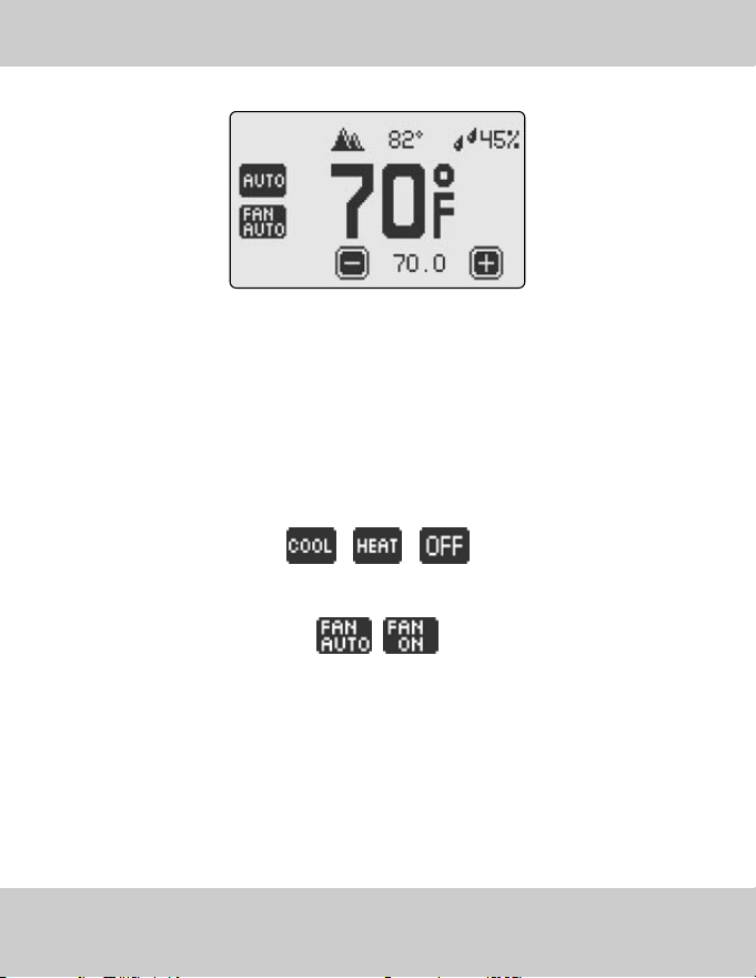
Current Room
Temperature
Current Room Humidity
Current Outdoor
Temperature
Current Thermostat Operation
Mode
Current Temperature
Control Mode
Current Fan
Operation Mode
Fan Operation Indicator
Vacation Mode Indicator
Security Indicator
Heat setpoint
Cool setpoint
Date
Time
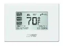
HOME SCREEN
16 LUXPRO
®
PSPU732T
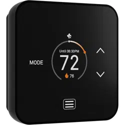
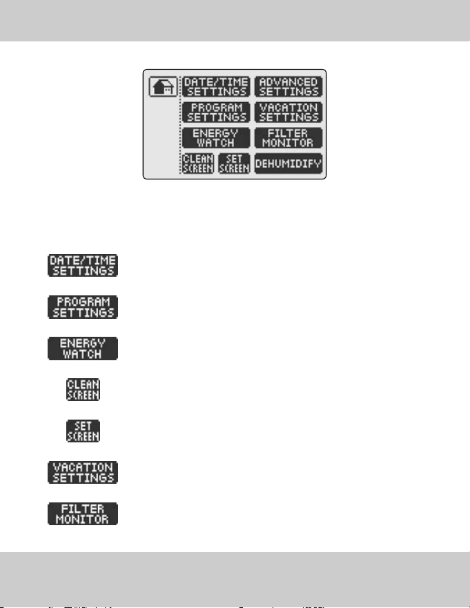
>> To return to the HOME SCREEN, simply touch the icon at any time!
>> The HOME SCREEN displays the following information:
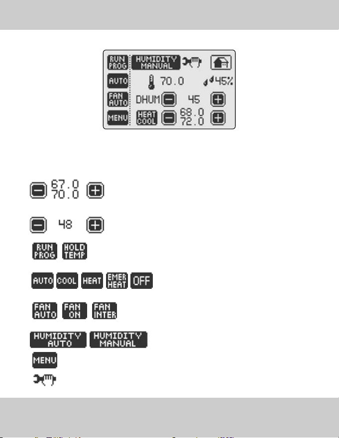
Change the Temperature Setpoint(s) using - and + buttons.
In AUTO MODE toggle the Heat/Cool button (Heat or Cool will flash
once selected), then raise or lower setpoints as desired.
Change the Humidity Setpoint using - and + buttons.
Select the Thermostat Operation Mode by toggling thermostat operation
mode button.
Select the Temperature Control Mode by toggling the
temperature control mode button.
Select the Fan Operation Mode by toggling the fan operation
mode button.
Select the Humidity Control mode by toggling the
humidity control mode button.
1
Access MENU SCREEN to enter into all thermostat features and settings.
Displays Installer Message to review important information.
>> To access the CONTROL SCREEN, simply touch the HOME SCREEN Screen… anywhere!
>> From the CONTROL SCREEN, you can:
CONTROL SCREEN
17INSTRUCTION MANUAL
1
Available only in combination with WIRELESS OUTDOOR TEMPERATURE TRANSMITTER AND RECEIVER KIT (WTR064)
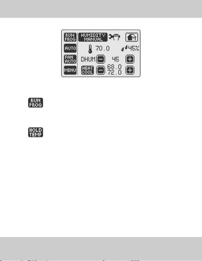
THERMOSTAT OPERATION MODES
18 LUXPRO
®
PSPU732T
>>LUXPRO
®
thermostat can operate in PROGRAM MODE or can HOLD a fixed temperature.
RUN PROGRAM: the thermostat initiates the 7-day Programmable Temperature
Control Program with 4 independent events per day. To set up a custom tem-
perature control program with customizable Temperature Setpoint and Fan
operation mode, refer to Section PROGRAM SETTINGS (page 27).
HOLD TEMPERATURE: the thermostat regulates the room temperature
as determined by the selected Temperature Setpoint.
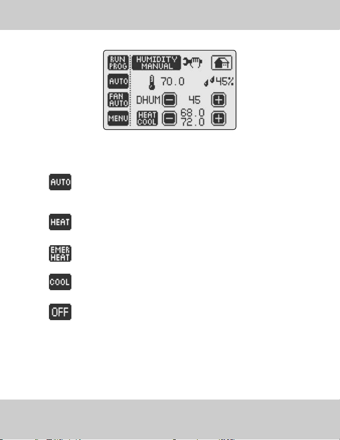
>>Based on your HVAC equipment LUXPRO
®
thermostat can operate in the following tempera-
ture control modes - AUTO or HEAT or EMERGENCY HEAT or COOL or OFF
AUTO - the thermostat keeps the room temperature between the selected
HEAT and COOL setpoints by using both the cooling and heating HVAC units.
HEAT - the thermostat only turns on the heating units to regulate room
temperature.
EMERGENCY HEAT - the thermostat enables the emergency heat (if
required).
COOL - the thermostat only turns on the air conditioning to regulate room
temperature.
OFF - the thermostat will not control temperature. the thermostat will
continue to display the current room temperature, current room humidi-
ty and outdoor temperature.
TEMPERATURE CONTROL MODES
19INSTRUCTION MANUAL
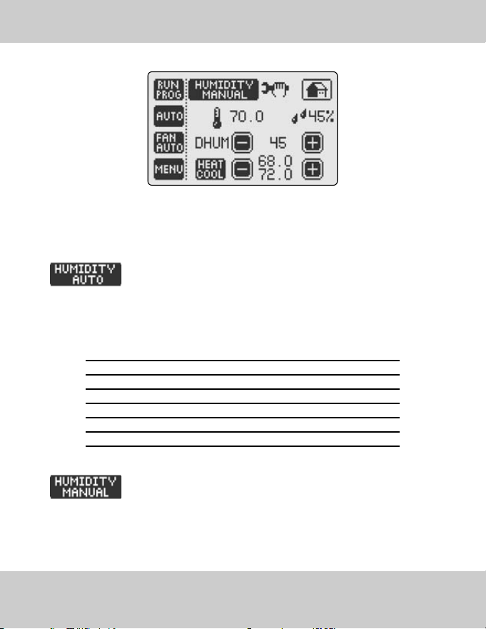
AUTOMATIC HUMIDITY CONTROL
20 LUXPRO
®
PSPU732T
>>In order to reduce condensation, humidity must be controlled and air movement must be
generated. As the exterior temperature drops, the humidity level needs to decrease if
condensation is to be controlled.
HUMIDITY AUTO: the thermostat automatically adjusts the humidity set
point based on the current indoor temperature and humidity as well as
the current outdoor temperature in order to maintain a maximum com-
fort level and eliminate condensation. The automatic humidity setpoint is
determined according to the following standard humidity table.
1
Setpoint Outdoor Temp in °C Outdoor Temp in °F
15% -29°C -20°F
20% -24°C -10°F
25% -18°C 0°F
30% -12°C 10°F
35% -7°C 20°F
40% -7°C -20°F
HUMIDITY MANUAL: The user selects the humidity setpoint.
1
Available only in combination with WIRELESS OUTDOOR TEMPERATURE TRANSMITTER AND RECEIVER KIT (WTR064)

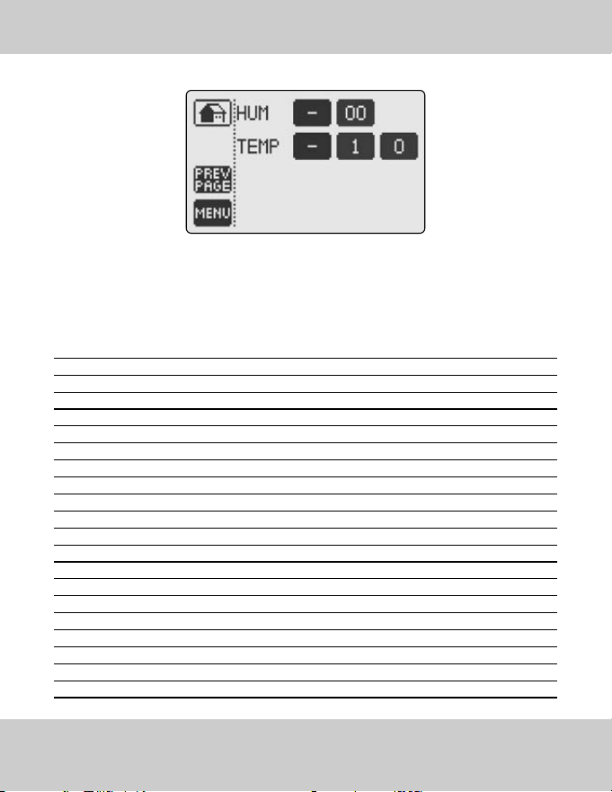
>>HUMIDIFY SETPOINT: Allows you to increase and maintain the relative humidity at a specif-
ic setpoint. Once you choose HUMIDIFY follow these easy steps:
• The HUM setpoint with - and + icons allow you to lower and raise your setpoint.
* Example of the typical use of the Humidify Function: If the current humidity is 30% your LUXPRO
®
thermostat will initiate the humidifier to function until Setpoint 50% is reached. In order to humid-
ify you must set the humidity setpoint above the current humidity.
HUMIDIFY AND HUMIDITY SETPOINT
21INSTRUCTION MANUAL

DE-HUMIDIFY AND HUMIDITY SETPOINT
22 LUXPRO
®
PSPU732T
>>DE-HUMIDIFY SETPOINT: Allows you to reduce and maintain the relative humidity at a
specific setpoint.
>>Please note that this feature functions in the COOL Mode only. Your LUXPRO
®
hermostat must be
configured to control a cooling unit such as an air conditioner of heat pump. Once you choose
De-Humidify follow these easy steps:
• The DH SETPOINT with - and + icons allow you to lower and raise your setpoint
>>Example of typical use of the De-Humidify function: In order to de-humidify you must set the de-humid-
ify setpoint below the current relative humidity. Your LUXPRO
®
thermostat will both lower and reg-
ulate temperature to the cooling setpoint while monitoring and lowering the room humidity.
Since the De-Humidify feature uses the COOL Function of your Air Conditioner or Heat Pump,
your LUXPRO
®
thermostat will turn off the air conditioning if either the dehumidifier setpoint or
temperature setpoint is reached - which ever comes first.
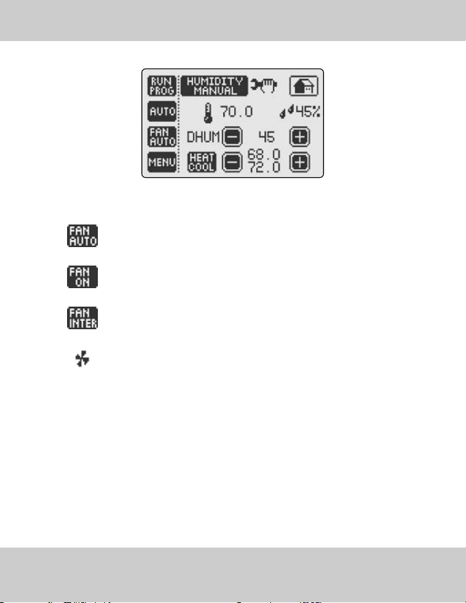
FAN OPERATION MODES
23INSTRUCTION MANUAL
>>LUXPRO
®
thermostat can operate the fan in one of the following three modes:
FAN AUTO: The fan runs only when there is a demand for heating or cool-
ing.
FAN ON: The fan runs continuously
FAN INTERMITTENT: The fan runs 10 minutes per 1/2 hour providing a
convenient way to improve air quality and save energy.
When the fan is running, the animated fan icon will appear on the
HOME SCREEN.
MENU SCREEN
24 LUXPRO
®
PSPU732T
>>To access the MENU SCREEN, simply touch MENU from the CONTROL SCREEN.
>>From the MENU page, you can:
Access DATE AND TIME SETTINGS to enter the accurate date and time
Access PROGRAM SETTINGS to pre-program temperature changes
during each day of the week.
Access ENERGY WATCH to display kWh consumption and the dollar cost
of operating the HVAC System
CLEAN SCREEN places the touch screen in a sleep mode for 15 seconds
which allows you to wipe the screen with a dampened cloth.
Access the SET SCREEN menu to change screen properties.
Access VACATION SETTINGS to activate the VACATION MODE
Access FILTER MONITOR to review days of "fan run time."
MENU SCREEN
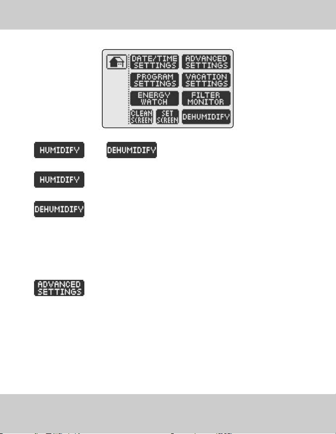
Select HUMIDIFY or DE-HUMIDIFY Control Mode
by toggling the humidity control mode button.
HUMIDIFY increases and maintains the relative humidity of the room at
a humidity setpoint selected on the CONTROL SCREEN.
DE-HUMIDIFY reduces and maintains the relative humidity of the room at
a humidity setpoint selected on the CONTROL SCREEN.
Please note that DE-HUMIDIFY feature functions only in COOL mode. LUXPRO
®
thermostat will regulate
both the room temperature and the room humidity at the same time. If DE-HUMIDIFY setpoint reached before
the temperature COOL setpoint, the air conditioning will turn off before the temperature setpoint is
reached. This feature has been specially designed to save energy without compromising the comfort.
Access ADVANCED SETTINGS to configure the thermostat.To access the
ADVANCED SETTINGS, hold the ADVANCED SETTINGS button for 5 sec-
onds. The thermostat will continuously beep for 5 seconds to indicate that
you are in the process of entering this feature.
! CAUTION Altering the system properties in the ADVANCED SETTINGS may affect the perform-
ance of the HVAC system and should be performed only by a qualified installer.
25INSTRUCTION MANUAL
26 LUXPRO
®
PSPU732T
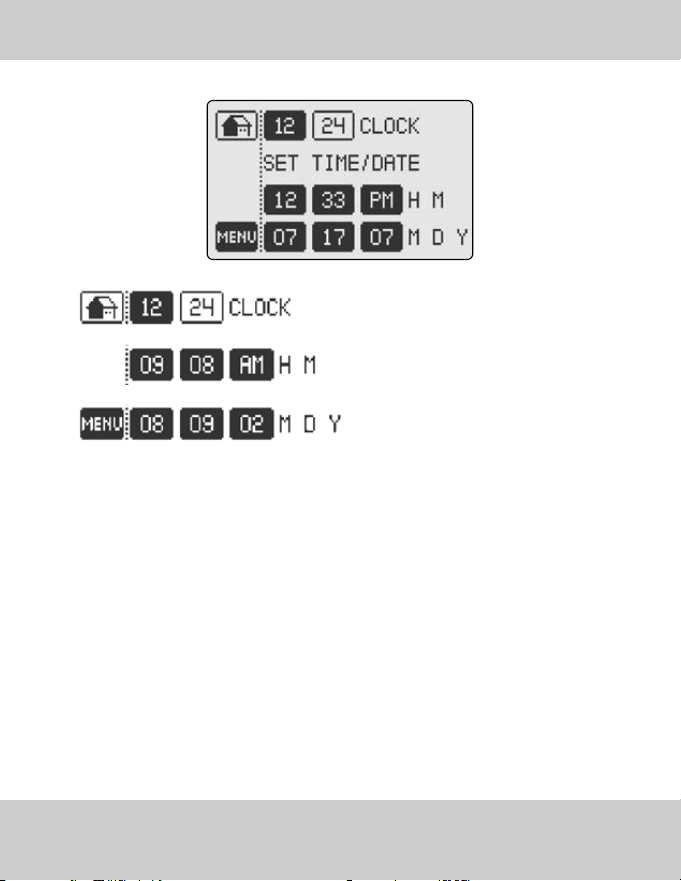
DATE AND TIME SETTINGS
Select the 12 OR 24 HOUR CLOCK display by
pushing the corresponding button.
Set the TIME by togggling hour, minute and
AM/PM buttons.
Set the DATE by toggling Month, Day and Year
buttons.
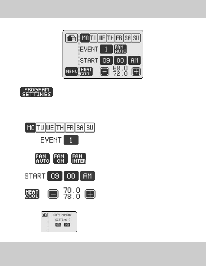
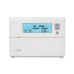
PROGRAM SETTINGS
PROGRAM SETTINGS feature allows you to easily and quickly program
daily temperature changes to fit your lifestyle and reduce energy con-
sumption. You can customize the program for each day of the week with
4 independent temperature and fan operation settings per day. To setup
your program:
Select the DAY OF THE WEEK
Select the EVENT NUMBER by toggling the
Event Number button
Choose desired FAN OPERATION MODE by
fan operation mode button.
Enter the event START TIME with Hour/Minute
and AM/PM buttons
Choose desired TEMPERATURE SETPOINT
with - and + buttons
Select the next event and repeat the steps
described above. Once finished, select the next
day of the week that you would like to program. the
thermostat will prompt you to copy the settings.
Repeat steps to program other days of the week.
27INSTRUCTION MANUAL
28 LUXPRO
®
PSPU732T
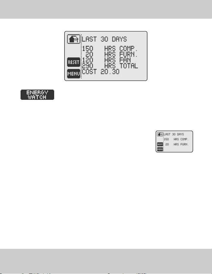
ENERGY WATCH
ENERGY WATCH feature provides a report on the energy consumption and
the dollar cost of operating your HVAC system (for up to the last 255 days).
Once the cost of the kWH per compressor, furnace and fan have been entered into the ENERGY
WATCH Settings (see page 32) Energy Watch will display the consumption as well as the real time
dollar cost of the HVAC system.
Otherwise, ENERGY WATCH will display only the total time the Compressor
and the Furnace have been operating.
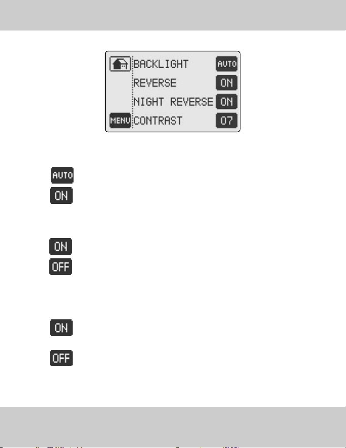
SET SCREEN OPTIONS
• BACKLIGHT: Select between automatic and permanent backlight for the screen.
AUTO: The screen back-light will come on only when you touch the screen.
ON: Screen will constantly be back-lit.
• REVERSE: Select the positive or negative screen display.
ON: Negative Display (Dark Background)
OFF: Positive Display (Light Background)
• NIGHT REVERSE: changes the touch screen background at night for improved display under
low-lighting conditions. Select between:
ON: the screen automatically reverses the background at 9PM and returns
to the normal display at 6:00AM .
OFF: screen background is determined by REVERSE function.
• CONTRAST: Toggle the screen contrast settings button (1-10) to select the screen contrast that
suits best your thermostat surroundings. LUXPRO
®
recommends the setting of 7.
29INSTRUCTION MANUAL
30 LUXPRO
®
PSPU732T
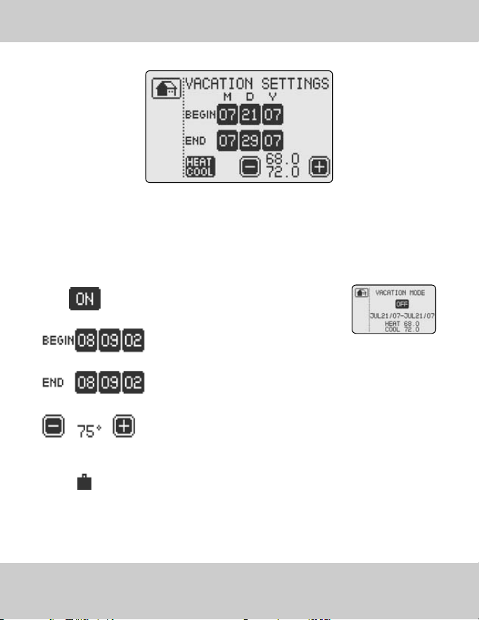
VACATION MODE
>>VACATION SETTINGS allows you to set the temperature to a fixed setpoint during the time you
are on vacation, providing energy savings without compromising comfort upon your return.
IMPORTANT: HEAT or COOL must be selected from the CONTROL SCREEN before entering the
Vacation Settings screen.
To begin select Vacation Mode ON:
Select the START Date
Select the END Date
Adjust the HEAT or COOL temperature setpoint: the Vacation mode begins
at 10 PM on the day of your departure and ends at Midnight on the day
of your arrival.
When the Vacation mode is active the suitcase icon appears on the HOME
SCREEN. Upon your return, the message VACATION MODE ENDED will be
displayed on the screen. Simply touch the screen, and your LUXPRO
®
thermostat will automatically revert to the Program Settings if you are in
RUN PROGRAM or to HOLD TEMPERATURE operation mode.
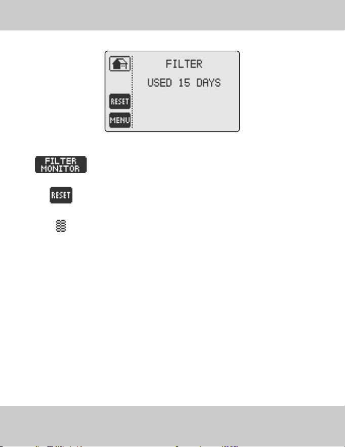
FILTER MONITOR
FILTER MONITOR: Displays filter usage in days
RESET: Resets filter timer (You should reset FILTER MONITOR after chang-
ing the air filter.
When activated the FILTER MONITOR icon appears on your HOME SCREEN
- this feature must be activated in ADVANCED SETTINGS.
31INSTRUCTION MANUAL
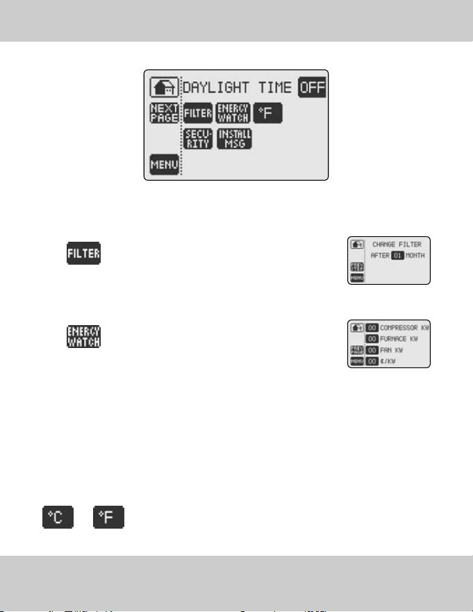
• DAYLIGHT TIME: Choose Daylight Time ON or OFF dependent on your Time Zone.
FILTER: Enter the air filter "fan run time" infor-
mation here. The Filter Monitor feature uses this
information to inform you when to change your
air filter by displaying CHANGE FILTER icon on the
HOME SCREEN.
ENERGY WATCH: Enter the HVAC system con-
sumption parameters (rounded off to kW) as well
as your electrical energy cost (¢/kW) and the
ENERGY WATCH feature will display a real time
totals of electrical energy consumption and cost. To
review touch the ENERGY WATCH button on the
MENU SCREEN.
* EXAMPLE: Fan 1kW, Heat Pump 1kW/ton, Furnace 5-30 kW, 7-9¢/kW
ENERGY WATCH feature will run consecutively for 255 days. If you do not enter your information what
will appear on the display is the total time the Compressor and the Furnace have been operating.
Select temperature display in either CELSIUS or FAHRENHEIT degrees
by toggling the °C / °F button to either °C or °F.
ADVANCED SETTINGS - FEATURES SETTINGS
32 LUXPRO
®
PSPU732T
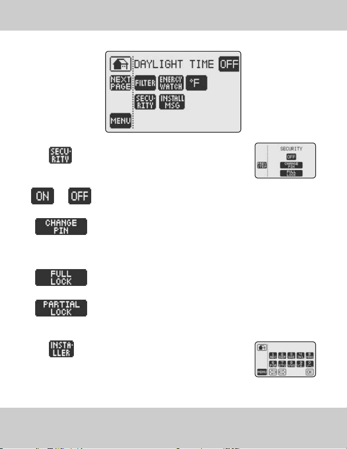
SECURITY: The security settings allow you to
protect your LUXPRO
®
thermostat from unautho-
rized use.
Turn Security ON or OFF. You will be prompted to enter the PIN. The Default
PIN 1111.
To CHANGE PIN, enter your new PIN and then, when prompted, re-enter
your new PIN.
Choose a security mode by toggling SECURITY MODE button:
FULL LOCK does not allow any changes unless the user enters the PIN.
PARTIAL LOCK allows you to change only the temperature setpoint
without entering a PIN.
Enter the INSTALLER MESSAGE: (up to 42 char-
acters) to appear at programmable intervals. Type
the message using the keyboard, and push OK button to confirm. You will
be prompted to enter the number of months after which you would like the
message to appear.
ADVANCED SETTINGS - FEATURES SETTINGS
33INSTRUCTION MANUAL

ADVANCED SETTINGS - SYSTEM CONFIGURATION
34 LUXPRO
®
PSPU732T
! IMPORTANT: By inadvertently modifying system configuration settings, you may seri-
ously degrade HVAC system performance.
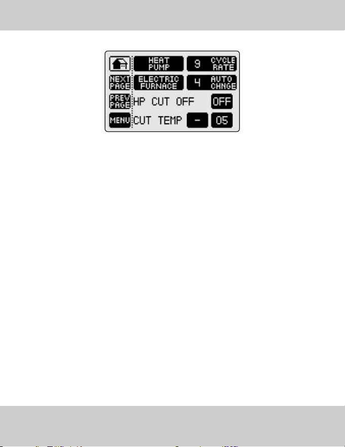
>>Choose system heating and cooling equipment - remember all you need to do is toggle the
appropriate button until the correct setting appears.
• Choose HEAT PUMP or 2 STAGE HEAT PUMP or AIR CONDITIONING or NO COMPRESSOR -
please review the wiring table and diagram for wiring instructions.
• Choose FURNACE OFF (No Furnace) or ELECTRIC FURNACE or EMERGENCY ELECTRICAL
FURNACE (additional electric furnace which will come on in emergency mode in conjunction
with electric furnace) or GAS FURNACE or OIL FURNACE or 2 STAGE GAS FURNACE; please
review the wiring table and diagram for wiring instructions.
• CYCLE RATE: Set Maximum compressor cycles per hour. We recommend that the factory default
be maintained for optimal performance..
• AUTO CHANGE: Set the minimum difference between Auto Mode, Heat and Cool temperature set-
points. We recommend that the factory default be maintained for optimal performance.
! IMPORTANT: This feature can only be activated when used with the LUXPRO
®
Outdoor
Wireless Temperature Transmitter and Receiver. Please install the LUXPRO
®
Outdoor
Wireless Temperature Transmitter and Receiver before activating this feature.
Increasing energy efficiency and reducing costs can be achieved by using the dual fuel
switch. Your heat pump can generally provide heat and comfort without assistance to an
outside temperature of just a few degrees below freezing. This temperature is called the
heat pump balance point. When the outside temperature is above the balance point, the heat
pump alone is sufficient for heating.
Once the outdoor temperature drops to the balance point the heat pump must be assisted by your
alternate energy source. When the outdoor temperature drops below the systems normal crossover
temperature (-12°C or -15°C), your heat pump will stop operating and the alternate energy
source will take over.
• HP Cut ON or OFF
• Cut Temperature:
+/-Temperature in Celsius (-5°C to 25°C)
+/- Temperature in Fahrenheit (13°F to 41°F)
ADVANCED SETTINGS - DUAL FUEL SWITCH
35INSTRUCTION MANUAL
ADVANCED SETTINGS - DIFFERENTIAL SETTINGS
36 LUXPRO
®
PSPU732T
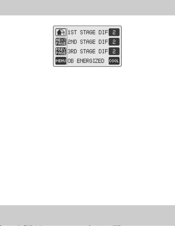
>>LUXPRO
®
PSPU732T allows you to control up to 3 Stages of Heating and 2 Stages of
Cooling, dependent on the type of system you have configured.
• 1ST STAGE DIFFERENTIAL: Set temperature difference between temperature set point and
actual temperature reading before 1st stage heating or cooling is initiated.
• 2ND STAGE DIFFERENTIAL: Set temperature difference between 1st stage initiation and 2nd stage
heating or cooling initiation.
• 3RD STAGE DIFFERENTIAL: Set temperature difference between 2nd stage initiation and 3rd stage
heating or cooling initiation.
• OB ENERGIZED: Reverses the Heat Pump OB Valve contact to HEAT or COOL (manufacturer
dependent).
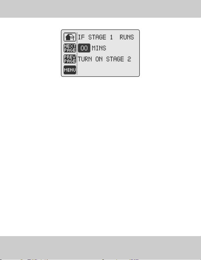
• Specify the number of minutes for which Stage 1 will function until Stage 2 is activated to help
raise (or cool) temperature (if the temperature set point is not reached). This unique function
avoids excess compressor wear in the case where the necessary temperature set point is not met
through setting of the Staging Differential. Set to “00” to disable.
ADVANCED SETTINGS - TIMER FEATURE
37INSTRUCTION MANUAL
ADVANCED SETTINGS - HEAT PUMP
38 LUXPRO
®
PSPU732T
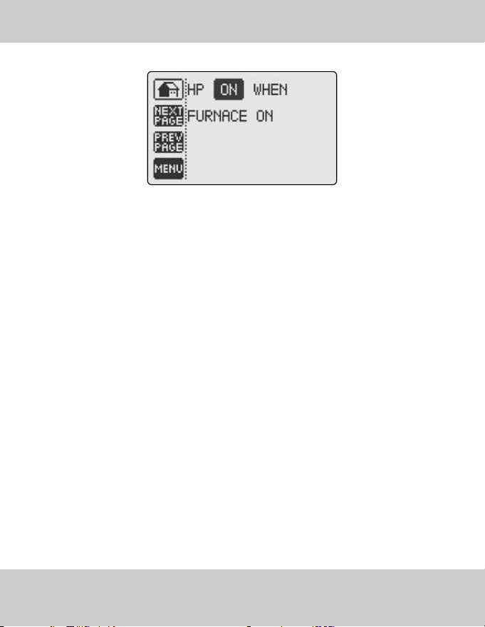
• HP ON when Furnace On: Heat Pump and Furnace can operate together when 2nd stage fur-
nace is required. HP “OFF” when Furnace On: turns off the Heat Pump when the furnace is On
(required on some gas or oil furnaces).

>>IMPORTANT: The Automatic Humidity Control feature can only be activated when used
with the LUXPRO
®
Outdoor Wireless Temperature Transmitter and Receiver. Please install
the LUXPRO
®
Outdoor Wireless Temperature Transmitter and Receiver before activating
this feature.
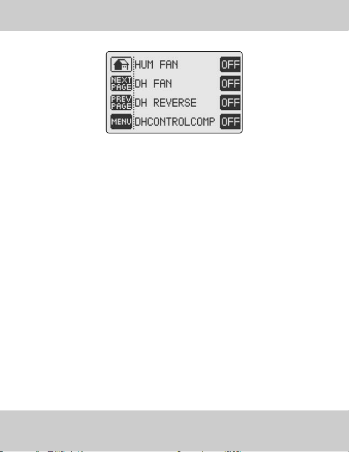
Automatic Humidity Control: Automatic humidity control is an option that lets your system automat-
ically adjust indoor humidity based on current outdoor conditions. This function minimizes destruc-
tive condensation build-up on your windows.
• HUM FAN: ON - fan runs when there is an independent demand to humidify. OFF: fan only runs
when there is a demand to humidify while heating or cooling.
• DH FAN: ON - fan runs when there is an independent demand to dehumidify. OFF: fan only runs
when there is a demand to dehumidify while cooling.
• DH REVERSE: ON - DH relay is normally closed when relative humidity is above DH set point.
OFF: DH relay is normally open when relative humidity is above DH set point.
• DH CONTROL COMPRESSOR: ON - Thermostat will turn off the air conditioning if either the dehu-
midify set point or the temperature set point is reached, whichever comes first, both DH relay and
compressor will turn off. OFF: DH relay is independent of compressor activity (DH becomes a spare
relay and can be used for a variable speed fan or separate dehumidifier or air exchanger)
ADVANCED SETTINGS - HUMIDITY SETTINGS
39INSTRUCTION MANUAL

ADVANCED SETTINGS - HUMIDITY SETTINGS
40 LUXPRO
®
PSPU732T
>>Operating Tips
• HUMIDIFICATION FAN should be set to ON when running steam or mist humidifiers.
• HUMIDIFICATION FAN should be set to OFF when running drum humidifiers or any other humid-
ifier that requires the furnace to run in order to make humidity.
• DE-HUMIDIFICATION FAN (DH) should be set to on when running separate de-humidification
equipment.
• DE-HUMIDIFICATION FAN (DH) may be set to off when using the air conditioning as a means of
de-humidification. It may advantageous in some environments to turn the fan on independent-
ly when there is a call for DH in order to distribute the humidity level more evenly.
• DH REVERSE function can be configured to meet the requirements of many variable speed fans,
consult the manual of your variable speed fan and determine if an “open” or “closed” contact
results in slowing fan operation.
>>De-humidification options for increasing comfort and efficiency
• HRV/ERV units can be controlled by simply connecting the DH terminal on the thermostat to the
terminal DH of the HRV/ERV. Most HRV/ERV units will control properly with the DH REVERSE fea-
ture turned off (contact normally open).
• OPTION 1: In Advanced Settings choose DHControlComp, set to ON then lower the temperature
to a minimum safe set point, finally set the desired de-humidity level, de- humidify will control
the compressor (unless minimum temperature set point is reached) whichever comes first.
• OPTION 2: Connect terminal DH to Y1 and set thermostat to de-humidify mode then regardless
of temperature the de-humidification setting will have priority. Caution: This method will run the
compressor until the de-humidification level is reached and may cause overcooling.
• OPTION 3: Connect the DH terminal to a variable speed fan control, (set DH REVERSE to control
the fan so that low speed is activated to de-humidify). This method provides maximum comfort
while maintaining the temperature in cooling mode.
ADVANCED SETTINGS - HUMIDITY SETTINGS
41INSTRUCTION MANUAL
ADVANCED SETTINGS - CALIBRATION
42 LUXPRO
®
PSPU732T
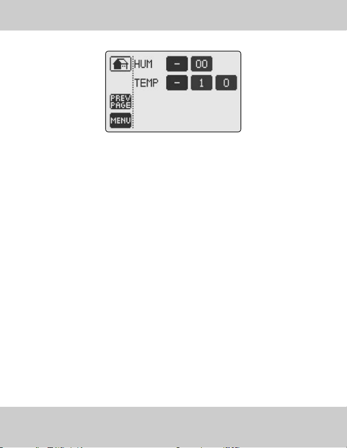
>>Calibration of Temperature or Relative Humidity
Your LUXPRO
®
thermostat is rated for ±1°F (±0.5°C) temperature accuracy and ± 4% for relative
humidity accuracy.
If you have determined due to drafts, sunlight or other environmental factors that your thermostat
requires calibration, follow this easy guide. Common cause of offset are lack of air circulation,
drafts or skylights in the direct vicinity of your LUXPRO
®
thermostat.
Measure humidity with a conventional hygrometer or any other device that provides a accurate
reading. Compare to the humidity reading on your LUXPRO
®
thermostat and calibrate by ±20%..
>> Temperature Calibration Table
• Determine the temperature difference using an accurate thermometer and use the following table
to calibrate your thermostat. The thermostat temperature reading can be calibrated by ±19°F (±9.5°C).
ADVANCED SETTINGS - CALIBRATION
43INSTRUCTION MANUAL
Calibration Number °C Change °F Change
±0.0 ±0.0°F ±0.0°C
±0.5 ±1°F ±0.5°C
±1.0 ±2°F ±1.0°C
±1.5 ±3°F ±1.5°C
±2.0 ±4°F ±2.0°C
±2.5 ±5°F ±2.5°C
±3.0 ±6°F ±3.0°C
±3.5 ±7°F ±3.5°C
±4.0 ±8°F ±4.0°C
±4.5 ±9°F ±4.5°C
±5.0 ±10°F ±5.0°C
±5.5 ±11°F ±5.5°C
±6.0 ±12°F ±6.0°C
±6.5 ±13°F ±6.5°C
±7.0 ±14°F ±7.0°C
±7.5 ±15°F ±7.5°C
±8.0 ±16°F ±8.0°C
±8.5 ±17°F ±8.5°C
±9.0 ±18°F ±9.0°C
±9.5 ±19°F ±9.5°C
SIMPLE THERMOSTAT MODE
44 LUXPRO
®
PSPU732T
>>LUXPRO
®
thermostat can also function as a virtual non-programmable thermostat after it has been
switched to a “SIMPLE MODE”.
>>To enable “SIMPLE MODE”, press the reset button (take off the thermostat faceplate and press
the reset button located in the bottom right-hand corner). The message “Touch for simple ther-
mostat” will appear. Touch the screen immediately, and your LUXPRO
®
thermostat becomes a
simplified non-programmable thermostat.
>>“SIMPLE MODE” has the following temperature control modes:
>>“SIMPLE MODE” has the following fan operation modes:
Please note that when entering "Simple Mode" all configurations and settings are stored
permenantly.
>>To revert back to the Programmable LUXPRO
®
thermostat, simply press the reset button and
touch the screen when the message “Touch for Programmable Thermostat” appears.
? Touch screen buttons do not function properly. Remove cover, press the reset button located
in the bottom left corner then accurately touch 3 target centers on the screen when prompted.
? Air Conditioning does not turn on even when room temperature is higher then the temper-
ature set point set point. DHCONTROLCOMP is turned ON and dehumidify set point has been
reached. This will cause air conditioning to turn off. Lower Setpoint - Page 17, 21; Dh CON-
TROLCOMP - Page 39.
? Air conditioning turns on in HEAT mode and heating turns on in COOL mode. Reverse the
OB valve (see “Advanced Settings” Page 36).
? PARTIAL LOCK and FULL LOCK do not function. You must not touch the screen for 1 minute
for LUXPRO
®
thermostat to automatically lock.
? Thermostat appears normal until the screen becomes blank when the compressor or
heating system turns on. You need to connect the “C” wire. 4 wire system will not function
unless the heat and compressor contactors can supply enough current to power the thermo-
stat with only 4 wires, if you cannot hook up the “C” wire another possible solution is to connect
one 250 ohm 10 watt resistor in the HVAC room, for cooling problems between C and W or in the
case of heating problem between C and Y1.
? I forgot my PIN and cannot unlock the thermostat. Remove the cover plate, press the reset
button located in the bottom right corner, as soon as the message “touch to reset password”
appears touch the screen, your PIN will be erased and the thermostat will unlock.
TROUBLESHOOTING
45INSTRUCTION MANUAL

IMPORTANT NOTICE
46 LUXPRO
®
PSPU732T
>>WHEN USING THIS THERMOSTAT WITH A GAS FURNACE A COMMON WIRE (C) MUST BE
CONNECTED.
When working without a common wire:
>>A confirm in HEAT MODE the cooling does not switch on or B confirm in COOL MODE the heat do-
es not switch on.
>>If test A or B fail or the thermostat shuts down in either HEAT or COOL MODE then it is necessary
to connect a common wire, (C), alternatively it may be possible to solve this issue by simply
connecting the 250 ohm 10 watt resistor between C and W (in the case of a cooling problem -
see B) or between C and Y1 (in the case of a heating problem - see A) at the HVAC equipment.
>>When working without a common wire, A confirm that when there is a call for heat, cooling does
not also activate, and when there is a call for cool, heating does not also activate.
>>If using the configuration of Heat Pump and Furnace with no Common Wire confirm that when
Heat Pump and Furnace are working together (both stages are operating at the same time) that
the display does not go blank, if so you must use a Common Wire.
>>This thermostat is equipped to run with two separated power transformers if required RC and RH.
Terminals RC and RH are internally connected together however you should wish to use two
transformers simply cut with a blade the copper trace on the printed circuit board located
between the C and Y2 screw terminals.

HARDWARE
LUX Products Corporation warrants the original end user (“Customer”) that new LUXPRO
®
branded products
will be free from defects in workmanship and materials, under normal use, for three (3) years from the
original purchase date.
SOFTWARE
LUX Products Corporation warrants to Customer that the LUXPRO
®
thermostat software will perform in sub-
stantial conformance to its program specifications for a period of three (3) years from the date of the orig-
inal purchase.
EXCLUSIONS
This warranty excludes (1) physical damage to the surface of the product, including cracks or scratches
on the touch-screen or outside casing; (2) damage caused by misuse, neglect, improper installation, unau-
thorized attempts to open, repair, or modify the product, or any other cause beyond the range of intended
use; (3) damage caused by accident, fire, power changes, other hazard, or Acts of God; or (4) use of the prod-
uct with any device if such device causes the problem.
EXCLUSIVE REMEDIES
Should a covered defect occur during the warranty period and Customer notifies LUX Products Corporation,
Customer’s sole and exclusive remedy will be, at LUX Products Corporation’s sole option and expense, to repair
or replace the product. Replacement products or parts may be new or reconditioned or a comparable ver-
sion of the defective item. LUX Products Corporation warrants any replaced product or part for a period of
ninety (90) days from shipment, or through the end of the original warranty, whichever is longer.
OBTAINING WARRANTY SERVICE
Customer must contact and return product to a local LUX Products Corporation product dealer or installer
within the applicable warranty period to obtain warranty service. Dated proof of original purchase will be
required. LUX Products Corporation will not be responsible for Customer’s memory data contained in, stored
on, or integrated with any products returned to LUX Products Corporation for repair, whether under warran-
ty or not.
WARRANTY EXCLUSIVE
THE FORGOING WARRANTIES AND REMEDIES ARE EXCLUSIVE AND IN LIEU OF ALL OTHER WARRANTIES,
EXPRESS OR IMPLIED, INCLUDING WARRANTIES OF
MERCHANTABILITY, FITNESS FOR A PARTICULAR
PURPOSE, CORRESPONDENCE WITH DESCRIPTION, AND NON-INFRINGEMENT, ALL OF WHICH ARE EXPRESS-
LY DISCLAIMED BY
LUX Products Corporation
AND ITS SUPPLIERS.
DISCLAIMER
NEITHER LUX Products Corporation NOR ITS SUPPLIERS SHALL BE LIABLE FOR INCIDENTAL, CONSEQUEN-
TIAL, INDIRECT, SPECIAL, OR PUNITIVE DAMAGES OF ANY KIND, OR FINANCIAL LOSS ARISING OUT OF OR
IN CONNECTION WITH THE SALE OR USE OF THIS PRODUCT, WHETHER BASED IN CONTRACT, TORT (INCLUD-
ING NEGLIGENCE) OR ANY OTHER THEORY, EVEN IF LUX Products Corporation HAS BEEN ADVISED OF THE
POSSIBILITY OF SUCH DAMAGES. LUX Products Corporation’S ENTIRE LIABILITY SHALL BE LIMITED TO
REPLACEMENT OR REPAIR OF THE PRODUCT.
WARRANTY
47INSTRUCTION MANUAL

FCC STATEMENT THIS DEVICE COMPLIES WITH PART 15 OF THE FCC RULES. OPERATION IS SUB-
JECT TO THE FOLLOWING TWO CONDITIONS: (1) THIS DEVICE MAY NOT CAUSE HARMFUL INTER-
FERENCE, AND (2) THIS DEVICE MUST ACCEPT ANY INTERFERENCE RECEIVED, INCLUDING INTER-
FERENCE THAT MAY CAUSE UNDESIRED OPERATION.
TECHNICAL ASSISTANCE
If you have any problems installing or using this thermostat, please reread the instructions careful-
ly or visit our online technical support at www.luxproproducts.com.If you require assistance,
please call our Technical Assistance number between 8:00 a.m. and 4:30 p.m. Eastern Standard Time,
Monday through Friday. The number is (856) 234-8803.
DIMENSIONS
Case: 6.5” x 4.6” x 1.25”
Screen: 3.625” x 2.125”
ELECTRICAL RATING
24 volt AC/DC
Class 2 maximum 2 amps
Temperature Accuracy ±1°F (±0.5°C)
Humidity Accuracy ±4%RH
PATENTS
7,185,825; 7,156,318; 7,145,110; 7,050,026; 7,028,912; 6,902,117; 6,786,421; Other Patents Pending
PSPU732T MANUAL
PRINTED IN CHINA
LUX Products Corporation
6000 Commerce Parkway, Suite-I • Mt. Laurel, NJ 08054
(856) 234-7905 • FAX (856) 234-7825
http://www.luxproproducts.com