OCT21V1
OWNER’S GUIDE
serial number:
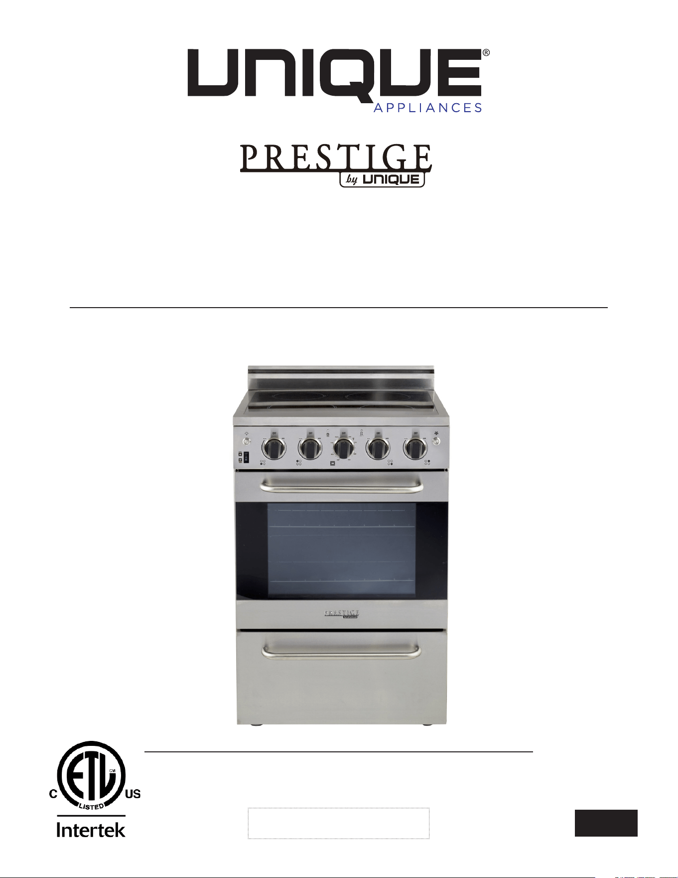
PRESTIGE 24" ELECTRIC
CONVECTION RANGE
24” - (60.9 cm)
MODEL NUMBER: UGP-24V EC S/S
4009900
Read and save these instructions
Installation & Owner’s Manual
This manual contains information for:
• Important Safeguards
• Installation
• Use and Care
Important
TO THE OWNER OF THE RANGE: Retain this owner’s manual for future reference.
TO THE INSTALLER: Leave this owner’s manual with the range.
Certain ranges come equipped with special features. Determine from a study of your
range which of the instructions given in this booklet pertain to your range.
This booklet gives valuable instructions covering the installation, adjustment and use of
your range.
How to Obtain Service and/or Parts
When your range does not operate in accordance with the instructions in the manual,
you should contact the dealer in your immediate vicinity for service. Or, the purchaser
may contact the service organization noted on the warranty.
PRESTIGE 24" ELECTRIC CONVECTION RANGE - (60.9 CM)
MANUFACTURED & CERTIFIED BY
Unique Appliances Ltd
2245 Wyecroft Road #5, Oakville, Ontario, Canada L6L 5L7
Phone: 905-827-6154 Toll Free: 1-877-427-2266 Email: info@UniqueAppliances.com
www.UniqueAppliances.com
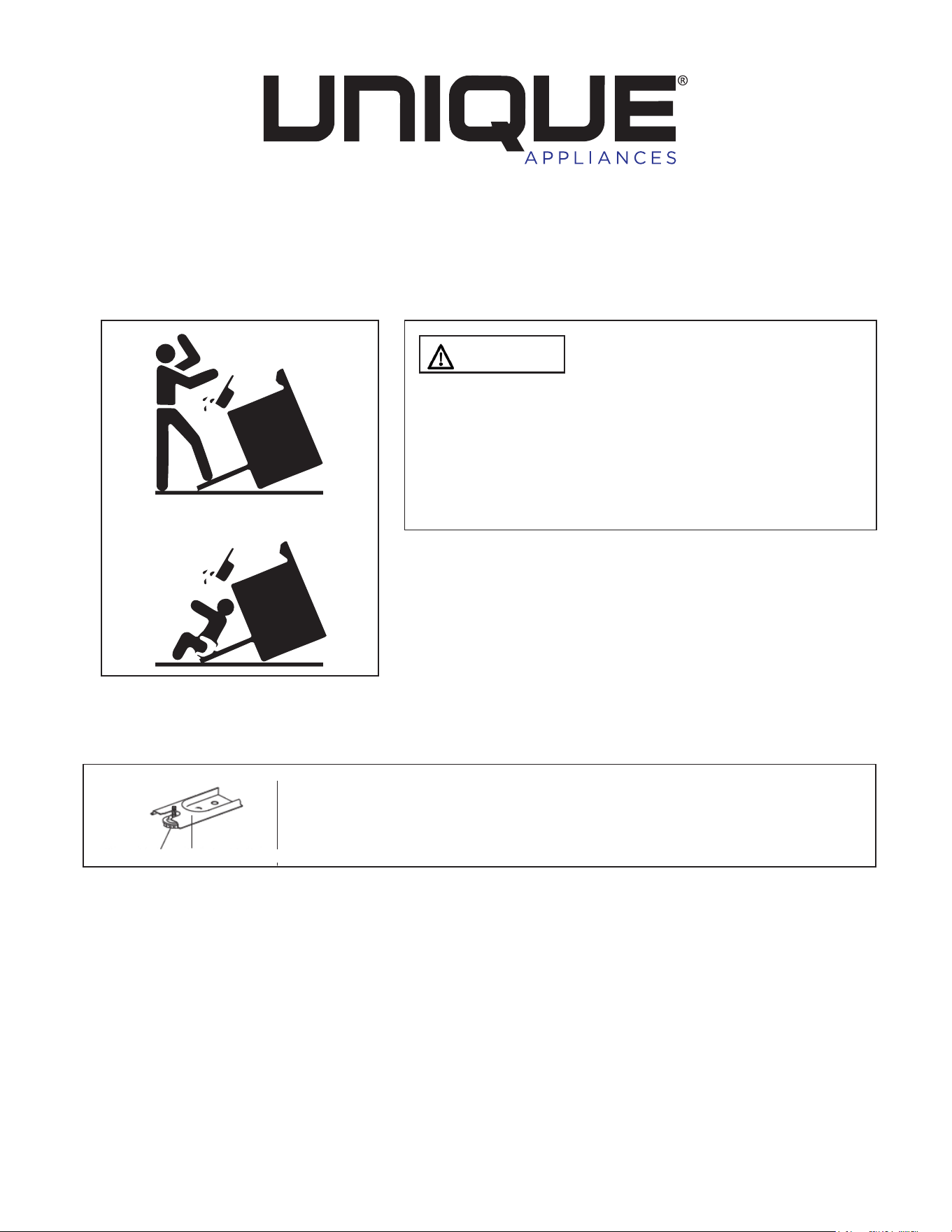
WARNING
To reduce the risk of tipping the
appliance by abnormal usage or improper door
loading, the appliance must be secured by properly
installing the Anti-Tip device packed with the
appliance. To check if the device is installed and
engaged properly. Carefully tip the range forward.
The Anti-Tip device should engage and prevent the
range from tipping over.
If this range is removed for any reason, service or
cleaning, etc., it must be replaced as outlined in the
installation instructions before placing the range back
in operation.
Making sure the anti-tip bracket is installed:
• Slide range forward.
• Look for the anti-tip bracket securely attached to floor.
• Slide range back so rear range foot is under anti-tip bracket.
X2
Range Foot Anti-tip Bracket

IMPORTANT SAFEGUARDS . . . . . . . . . . . . . . . . . . . . . . . . . . . . 6
HOW TO INSTALL THE BACKSPLASH . . . . . . . . . . . . . . . . . . . . . . . 11
INSTALLATION INSTRUCTIONS . . . . . . . . . . . . . . . . . . . . . . . . . . 12
WALL CLEARANCES & ANTI-TIP LOCATION . . . . . . . . . . . . . . . . . . 13
PARTS AND FEATURES . . . . . . . . . . . . . . . . . . . . . . . . . . . . . . . 15
OPERATION OF RANGE . . . . . . . . . . . . . . . . . . . . . . . . . . . . . . 16
OPERATION OF OVEN . . . . . . . . . . . . . . . . . . . . . . . . . . . . . . . 17
CARE AND MAINTENANCE . . . . . . . . . . . . . . . . . . . . . . . . . . . 20
CLEANING THE RANGE . . . . . . . . . . . . . . . . . . . . . . . . . . . . . . 23
TROUBLESHOOTING GUIDE . . . . . . . . . . . . . . . . . . . . . . . . . . . 25
WIRING DIAGRAM . . . . . . . . . . . . . . . . . . . . . . . . . . . . . . . . . 26
PARTS DIAGRAM AND LIST. . . . . . . . . . . . . . . . . . . . . . . . . . . . 27
RATING LABEL . . . . . . . . . . . . . . . . . . . . . . . . . . . . . . . . . . . 30
WARRANTY. . . . . . . . . . . . . . . . . . . . . . . . . . . . . . . . . . . . . . 31
APPLIANCE INFORMATION . . . . . . . . . . . . . . . . . . . . . . . . . . . 32
NOTES . . . . . . . . . . . . . . . . . . . . . . . . . . . . . . . . . . . . . . . . .32
PRODUCT REGISTRATION . . . . . . . . . . . . . . . . . . . . . . . . . . . . 32
CONTACT US . . . . . . . . . . . . . . . . . . . . . . . . . . . . . . . . . . . . 32
TABLE OF CONTENTS

5
Congratulations on your purchase of a UNIQUE range! We are very proud of our product – and
are completely committed to providing you with the best service possible. Your satisfaction is
our #1 priority. Please read this manual very carefully. It contains valuable information on how to
properly maintain your new Unique propane range.
We know you will enjoy your new range and Thank You for choosing one of our Unique
Appliances!. We hope you will consider us for future purchases.
PLEASE READ AND SAVE THESE INSTRUCTIONS
This manual provides specific operation instructions for your model. Use your range only as
instructed in this manual. These instructions are not meant to cover every possible condition
and situation that may occur. Common sense and caution must be practiced when installing,
operating and maintaining the appliance.
Record in the space provided below the Model No. and Serial No. of this appliance.
These numbers are found on the serial plate located at the bottom drawer.
Model No. ______________________
Serial No. ________________________
Purchase Date ________________________
Record these numbers for future use.
IMPORTANT: Keep a copy of your bill of sale. The date on the bill establishes the warranty
period should service be required. If service is performed, it is in your best interest to obtain
and keep all receipts.
PLEASE DO THIS NOW!
Please visit our website at https://UniqueAppliances.com/product-registration/ to register
your product.
WELCOME
NEED HELP?
6
USER SERVICING: Do not repair or replace any part of the appliance unless specifically
recommended in this owner’s guide. Only a qualified technician should do all other servicing.
This will reduce the risk of personal injury and damage to the range.
Storage in or on appliance: Flammable materials should not be stored in an oven, near
surface burners or in the broiler section. This includes paper, plastic and cloth items, such as
cookbooks, plastic ware and towels, as well as flammable liquids. Do not use the oven for
storage. Do not store explosives, such as aerosol cans, on or near the range.
Remove the oven door from any unused range if it is to be stored or discarded.
Stepping, leaning or sitting on the doors or broiler section of this range can result in serious
injuries and cause damage to the range.
The following situations could cause bodily injury or property damage.
DO NOT TOUCH SURFACE BURNERS, AREAS NEAR THESE BURNERS, OVEN BURNERS OR
INTERIOR SURFACES OF THE OVEN. Both surface burners and oven burners may be hot even
though o. Areas near surface burners may become hot enough to cause burns. During and
after use, do not touch, or let clothing or other flammable materials touch these areas until they
have had sucient time to cool. Among these areas are the range, surfaces facing the range,
the oven vent openings and surfaces near these openings, oven door and windows.
NEVER use this appliance as a space heater to heat or warm the room.
Wear proper apparel. Loose fitting or hanging garments should never be worn while
using the appliance. Do not let clothing or other flammable materials contact surface burners or
interior surfaces of the oven until they have had sucient time to cool.
Never modify or alter the construction of the range. Do not remove leveling legs, panels, wire
covers, anti-tip brackets or any other permanent part of the product.
When heating fat or grease, watch it closely. Fat or grease may catch fire if allowed to
become too hot.
Do not use water or flour on grease fires. Smother the fire with a pan lid, baking soda or use
a dry chemical or foam-type extinguisher.
Operation of the Surface Burners. When the burners are operated for the first time, a small
amount of smoke may be generated due to tape residue or manufacturing lubrication, this is
not dangerous. Operate the burners for about five minutes to rid the burners of this material
before cooking.
Use only dry potholders. Wet or damp potholders on hot surfaces could result in burns from
steam. Do not let the potholder touch hot heating areas. Do not use a towel or other bulky
cloth instead of a potholder.
NEVER cover any slots, holes or passages in the oven bottom or cover an entire rack
with materials such as aluminum foil. Doing so blocks air flow through the oven and
may cause carbon monoxide poisoning. Aluminum foil linings may also trap heat,
causing a fire hazard. Refer to the cleaning section of this manual for more information on the
use of aluminum foil.
IMPORTANT SAFETY NOTES
7
WARNINGS
Destroy the carton and plastic bags after the range is unpacked. Children should not use
packaging material for play. Cartons covered with rugs, bedspreads, or plastic sheets can become
airtight chambers. Remove all staples from the carton. Staples can cause severe cuts and destroy
finishes if they come in contact with other appliances or furniture.
Be safety conscious. The preparation of food in an oven requires temperatures that
could cause severe burns. Before using this new appliance, carefully read and follow all
instructions.
WARNING
PROP 65 WARNING FOR CALIFORNIA RESIDENTS
The California Safe Drinking Water and Toxic Enforcement Act of 1986 (Proposition 65)
requires the Governor of California to publish a list of substances known to the State of
California to cause cancer or reproductive harm. In addition, businesses must warn customers
of potential exposure to such substances
The following situations may cause serious bodily harm, death or property damage.
TO REDUCE THE RISK OF TIPPING OF THE RANGE, THE RANGE MUST BE SECURED BY A
PROPERLY INSTALLED ANTI-TIP BRACKET PROVIDED WITH THE RANGE. TO CHECK IF THE
DEVICE IS INSTALLED AND ENGAGED PROPERLY, CAREFULLY TIP THE RANGE FORWARD.
THE ANTI-TIP DEVICE SHOULD ENGAGE AND PREVENT THE RANGE FROM TIPPING OVER.
REFER TO THE INSTALLATION INSTRUCTIONS PACKAGED WITH THE ANTI-TIP BRACKET
FOR PROPER ANTI-TIP BRACKET INSTALLATION.
• Never leave children alone or unattended in the area where an appliance is in use. They
should never be allowed to sit or stand on any part of the appliance. Never leave the oven
door open when the range is unattended.
• Do not store items of interest to children in the cabinets above a range or on the
backguard of a range. Children climbing on the range to reach the items could be seriously
injured.
Do not allow children to climb or play around the range. The weight of a child on an open
oven door may cause the range to tip, resulting in serious burns or other injury.
IMPORTANT: Observe all governing codes and ordinances. Do not obstruct flow of heat and
ventilation.
IMPORTANT SAFETY NOTES

8
Placement of oven racks: Always place an oven rack in the desired location while the oven is
cool. If a rack must be moved when the oven is hot, use potholders and grasp the rack with
both hands to reposition. Do not let potholders contact hot oven walls. Remove all cookware
from the rack before moving.
Do not heat unopened food containers. Build-up of pressure may cause the container to
burst and result in injury.
Keep the oven vent duct unobstructed. The oven vent is located along the bottom of the
back guard. Touching the surfaces in the vent area when the oven is being operated may
cause severe burns. Also, do not place plastic or heat-sensitive items on or near the oven
vents. These items could melt or ignite. The range requires fresh air for proper burner
combustion. Do not block the flow of air around the base or beneath the lower front panel of
the range.
Use care when opening oven door: Stand to the side of the oven when opening the oven
door. Slowly open the door to allow hot air or steam to escape before removing or replacing
food.
Know which knob controls each burner. Place a pan of food on the burner before turning
it on, and turn the burner o before removing the pan. Always turn to the full position when
igniting top burners. Then adjust the flame size so it does not extend beyond the edge of the
cookware.
Cookware handles should be turned inward and not extend over adjacent surface burners.
To reduce the risk of burns, ignition of flammable materials, and spillage due to unintentional
contact with the cookware, the handle of a cookware should be positioned so that it is turned
inward, and does not extend over adjacent surface burners.
Never leave the surface burners unattended. Boilovers may cause smoking, greasy spill-
overs may catch fire or a pan which has boiled dry may melt.
Do not place hands between the spring tension hinge and the oven door frame when you
are removing the oven door. You could pinch your fingers.
Allow parts to cool to room temperature before touching or removing them from the
range. When a surface burner is first turned o, the burner and grate are hot enough to cause
burns.
When removing appliance for cleaning and/or service:
• Disconnect AC power supply.
• Carefully remove the range by pulling outward.
CAUTION: Range is heavy. Use care in handling.
Never clean appliance parts with flammable fluids. These fumes can create a fire hazard
or explosion. And do not store or use gasoline or other flammable vapors and liquids in the
vicinity of this or any other appliance. The fumes can create a fire hazard or explosion.
Before proceeding with cleaning and maintenance operations, make sure the power line of
the unit is disconnected.
Do not attempt to repair or replace any part of your appliance unless it is specifically
recommended in this manual. All other servicing should be referred to a qualified technician
Clean the range regularly to keep all parts free of fat or grease, which could catch fire.
Exhaust fan ventilating hoods and grease filters should be clean. Do not allow fat or grease
to accumulate. Greasy deposits in the fan could catch fire. Refer to the hood manufacturer’s
instructions for cleaning.
IMPORTANT SAFETY NOTES
9
Glazed cookware: Only certain types of glass, glass/
ceramic, ceramic, earthenware, or other
glazed cookware are suitable for rangetop service without breaking, due to the sudden
change in temperature. Check the manufacturer’s recommendations for rangetop use.
WARNING: Do not place lids on top of glass cooking surface when hot. Shattered cooktops
could happen when heat is trapped between the lid and the glass stovetop, creating a
strong vacuum seal. The air is forcefully sucked out and shatters the glass (This is not
covered by your warranty).
Do not place plastic salt and pepper shakers, spoon holders or plastic wrappings on top
of the range. These items could melt or ignite. Pot holders, towels or wooden spoons could
catch fire if placed too close to the heat.
Do not use a wok equipped with a metal ring.
Do not clean the oven door gasket. The door gasket is essential for a good seal. Care should
be taken not to rub, damage or move the gasket.
It’s good practice for each household to have an appropriate fire extinguisher for use in the
event of a house fire.
NOTE: When installing or removing the range for service, a rolling life jack should be used.
Do not push against any of the edges of the range in an attempt to slide it into or out of
the installation. Pushing or pulling a range (rather than using a lift jack) also increases the
possibility of bending the leg spindles or the internal coupling connectors.
NOTE: The instructions appearing in this owner’s guide are not meant to cover every possible
condition and situation that may occur. Common sense and caution must be practiced when
operating and maintaining any appliance.
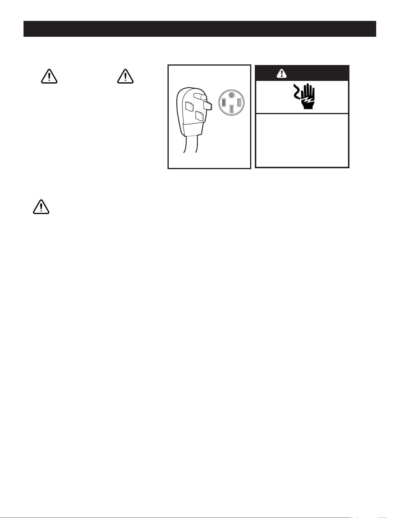
ELECTRICAL GROUNDING INSTRUCTIONS
FOR PERSONAL SAFETY, THIS APPLIANCE MUST BE PROPERLY GROUNDED.
This appliance is equipped with a four-prong grounding plug for your protection against
shock hazard and should be plugged directly into a properly grounded socket. Do not cut or
remove the grounding prong from the plug.
Do not under any circumstances cut or remove the third (ground) prong from the power plug.
Electrical installation should comply with national and local codes.
It is recommended that a separate circuit, serving only your appliance be provided. Use
receptacles that cannot be turned o by a switch or pull chain.
REPLACEMENT PARTS
Only authorized replacement parts may be used in performing service on the range.
Replacement parts are available from factory authorized parts distributors. Contact the
nearest Unique parts distributor in your area.
IMPORTANT SAFETY NOTES

10
WARNING
HAVE THIS RANGE INSTALLED BY A QUALIFIED INSTALLER.
Improper installation, adjustment, alteration or maintenance can cause injury or property
damage. Consult a qualied installer or service agency. It must be properly positioned and
installed as described in this manual, so read the manual carefully. To reduce the risk of
re, electrical shock or injury when using the appliance, follow basic precaution, including
the following:
BEFORE USING YOUR ELECTRIC RANGE:
• Remove the exterior and interior packing.
• Remove the protective film on steel and aluminum parts.
• Check to be sure you have all of the parts listed below.
• 1 backsplash
• 2 anti-tip brackets
• 2 oven racks
• 1 broiler griddle
• 1 broiler tray
• 2 screws for backsplash
• 1 instruction/installation manual
• Clean the interior surface with lukewarm water using a soft cloth
• Have your range installed and properly grounded by a qualifies installer in accordance with
the installation instructions
• Do not attempt to repair or replace any part of your range unless it is specifically
recommended in this manual.
• Do not remove permanently axed labels, warnings, or plates from the unit. This may void
the warranty.
• The installer should leave these instructions with the consumer who should retain for local
inspectors use and for future reference,
• Please observe all local and national codes and ordinances.
BEFORE USING YOUR RANGE
11
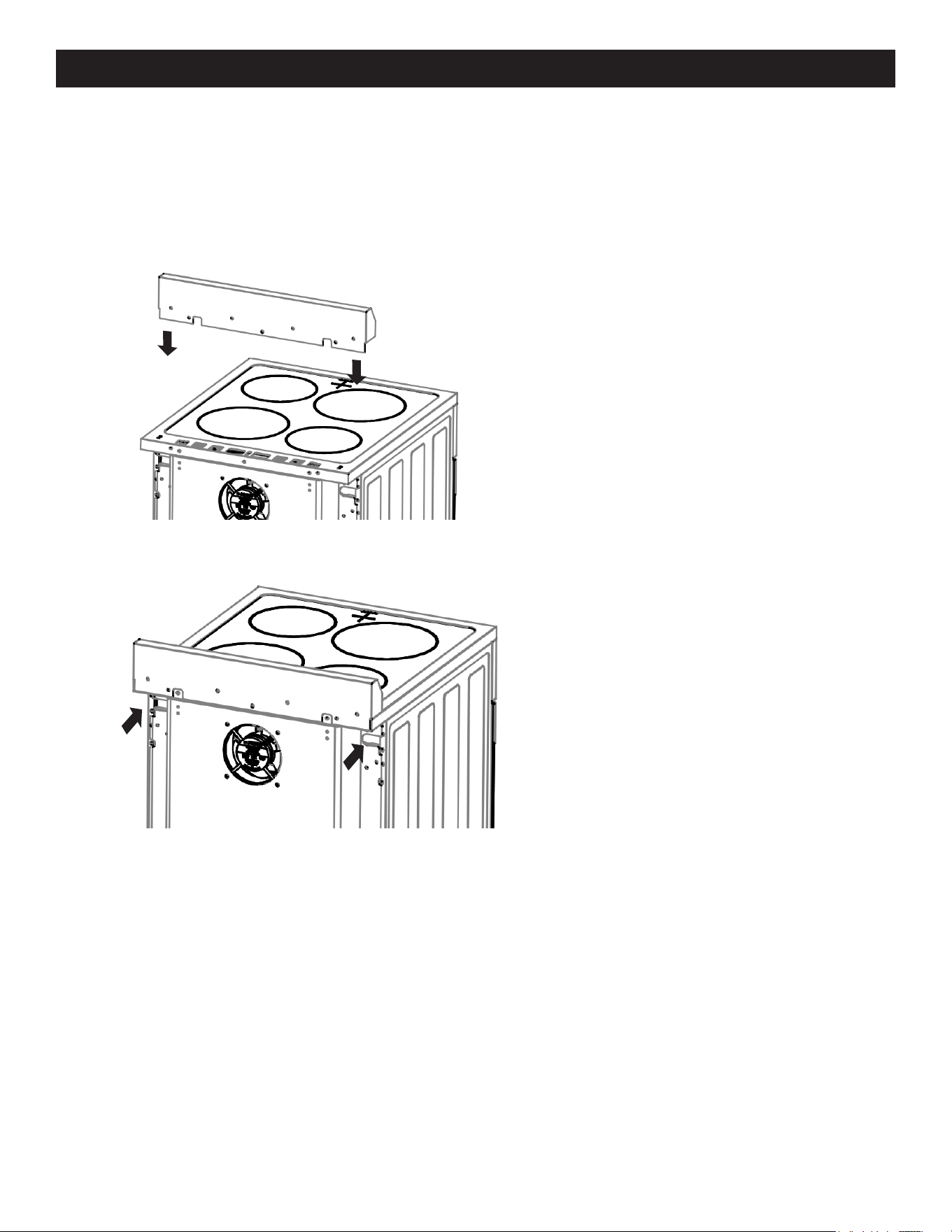
1. Align the backsplash to the
rear part of the cooktop as
shown in the diagram.
2. Secure the backsplash to the
cooktop from the back using
the 2 Phillips head screws
provided as shown in the
diagram.
HOW TO INSTALL THE BACKSPLASH
12
LEVELLING A FREE-STANDING RANGE
All free-standing ranges must be level to obtain proper cooking results. The leveling legs
should be screwed into the corner brackets. Place pan or measuring cup partially filled with
water or a level on the oven rack. Adjust the leveling legs until the range is level. The top of
the side panels should be level with the counter top.
WARNING
A child or adult can tip the range and
be killed. Install the anti-tip device to the structure and/
or the range. Verify the anti-tip device has been properly
installed and engaged. Engage the range to the anti-
tip device by ensuring the anti-tip device is re-engaged
when the range is moved. Re-engage the anti-tip device
if the range is moved. Do not operate the range without
the anti-tip device in place and engaged. See installation
instructions for details. Failure to do so can result in death
or serious burns to children or adults.
Making sure the anti-tip bracket is installed:
• Slide range forward.
• Look for the anti-tip bracket securely attached to floor.
• Slide range back so rear range foot is under anti-tip bracket.
X2
Range Foot Anti-tip Bracket
WARNING
INSTALLATION INSTRUCTIONS
13
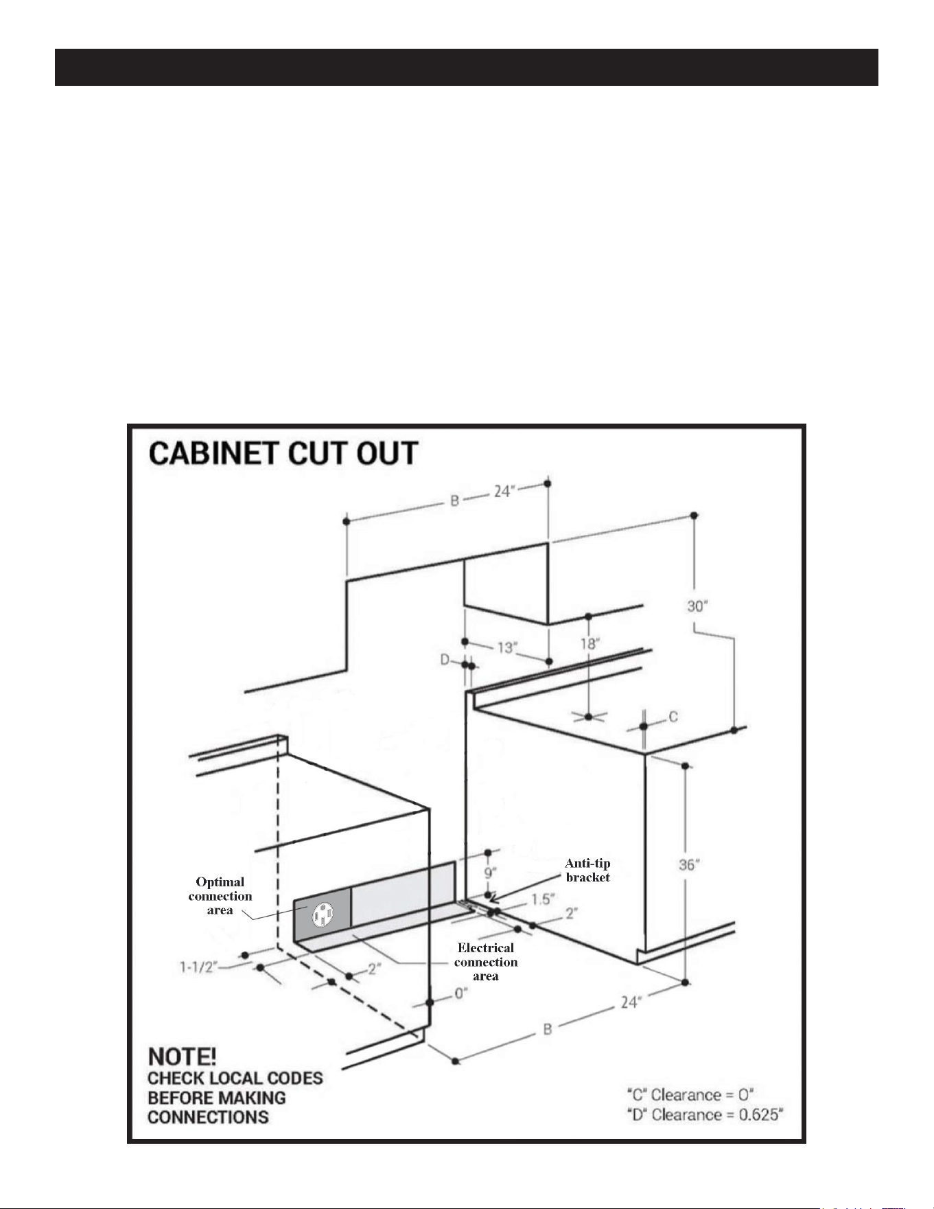
All units must be installed in accordance to minimum rear and side wall clearance and
clearances extended vertically above cooking top which are stated on the serial plate located
at the back of the range.
ANY OPENINGS IN THE WALL BEHIND THE UNIT AND IN THE FLOOR UNDER THE UNIT
MUST BE SEALED.
Note: Due to potential hazards it is recommended that storage cabinets NOT be installed
above the cooking surface.
IN THE EVENT OVERHEAD CABINETS ARE INSTALLED, THE MAXIMUM DEPTH OF
CABINETS INSTALLED ABOVE COOKING TOPS SHOULD BE 13”.
24”
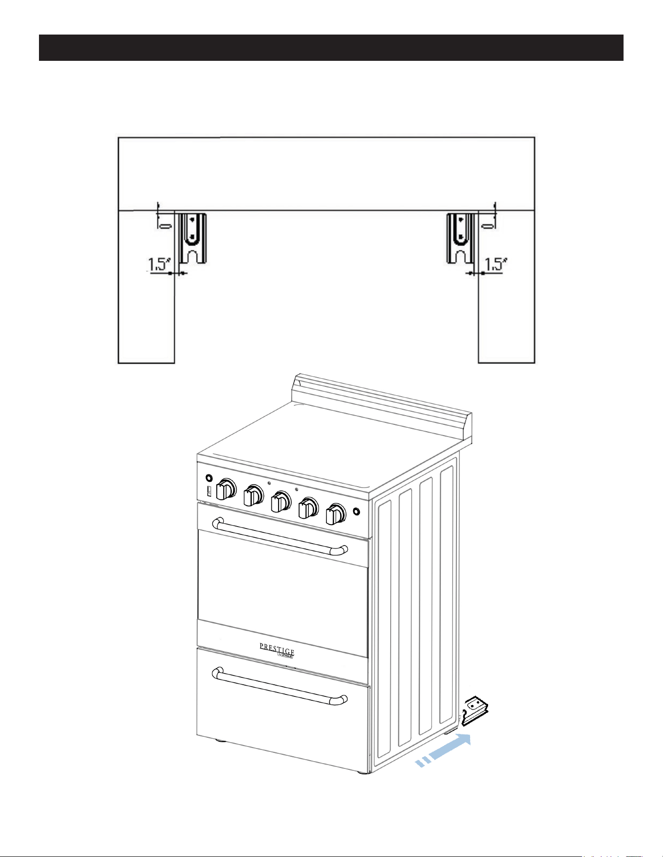
WALL CLEARANCES & ANTI-TIP LOCATION
14
Anti-Tip Bracket Location
WALL CLEARANCES & ANTI-TIP LOCATION (continued)
15
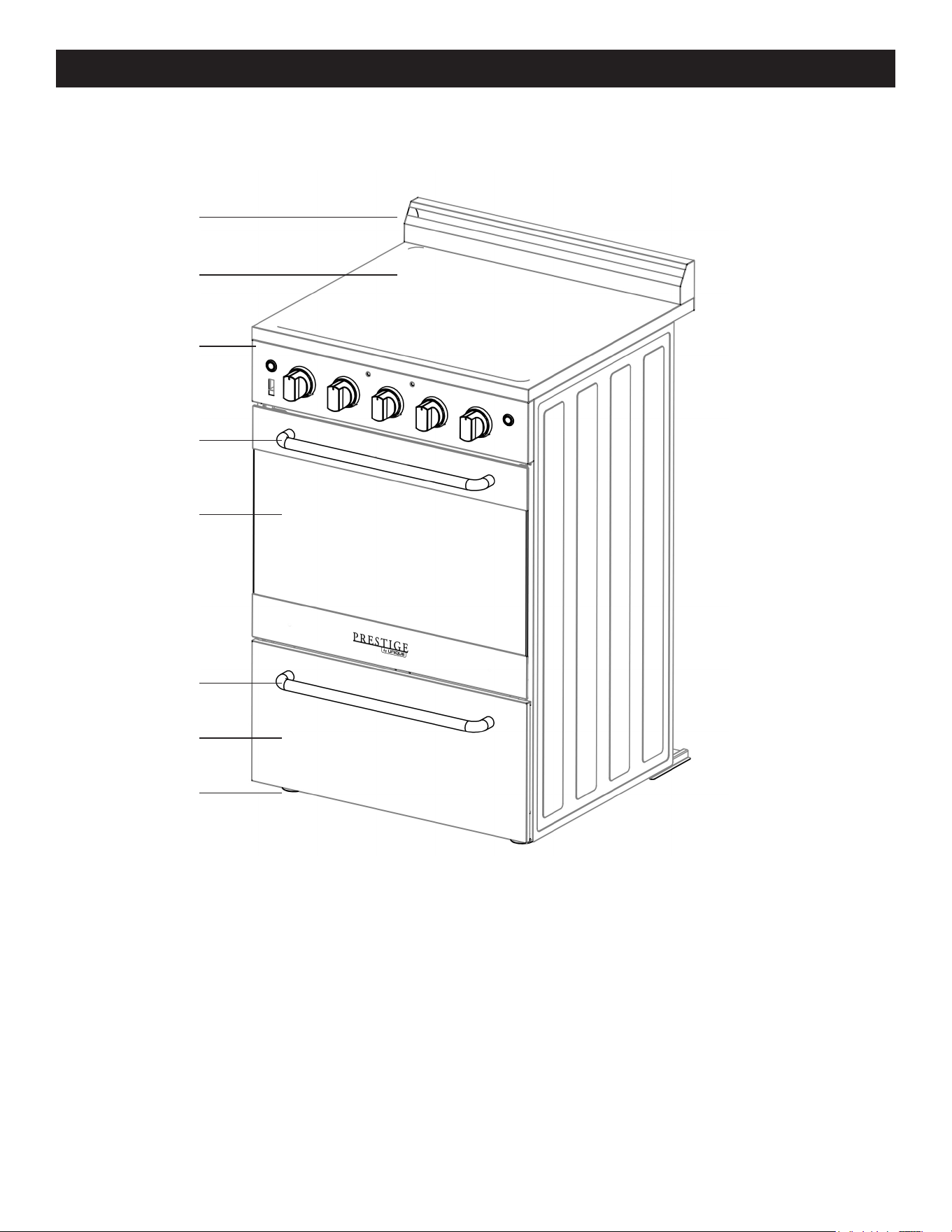
1. Backsplash with integrated oven vents
2. Cooktop
3. Control panel
4. Oven Handle
5. Oven Door
6. Storage Drawer Handle
7. Storage Drawer
8. Leveling Legs (4)
1
2
3
4
5
6
7
8
PARTS & FEATURES
16
Oven on/o indicator light
Burner position
Oven
Cooktop on/o indicator light
Rocker switch
Convection Fan
Light
Push & rotate right to use oven
Push & rotate right to use broiler
HOT SURFACE INDICATOR LIGHT WILL TURN ON WHEN THE COOKTOP IS BEING USED
AND WILL REMAIN LIT UNTIL THE SURFACE TEMPERATURE OF THE GLASS COOKTOP
RETURNS TO A SAFE TEMPERATURE
USING THE SURFACE UNITS
• Use care when touching the cooktop. The glass surface of the cooktop will retain heat after
the controls have been turned o.
• Do not use the cooktop if the glass is cracked or broken. Using the cooktop can present a
risk of electric shock. Contact a qualified technician immediately.
• Avoid scratching the glass. The cooktop can be easily scratched by using items similar to
knives, sharp object rings, jewelry.
• Avoid storing items that can melt or possibly catch fire on the glass cooktop, even if not in
use. In the even the cooktop is accidentally turned on and or heat from the oven vent may
cause items to melt or ignite.
• Never cook directly on the glass, always use appropriate cookware.
BURNER CONTROL KNOB
The range comes with four burners. To operate the burners simply push in and turn the knob
to the desired position. These controls go from low to high power output, having a number of
positions to switch o the burner, turn the burner control knob to the setting position.
Your range is equipped with four surface units with two dierent sizes. Two of them are 6”
and two of them are 8” in size. The surface controls are easily operated. Simply push In and
turn the knob to the desired position.
2 x 8” large burners: 1800 watts - 2 x 6” small burners: 1200 watts
OPERATION OF RANGE
17
When the element is energized, the indicator light will be lit regardless of the setting when
one or more of the elements are turned on. The control has a variable of power output from
lo to hi with a number of positions. The range of heat is increased by turning the knob to hi,
decreased by turning the knob to lo.
Important: to switch on, always lightly press the control knob
inwards then turn.
NOTE: Automatic cooling fan runs periodically at the back
of the range to cool the inside of the control panel, faint fan
noise can be heard which is normal operation.
To avoid overcooking, remove pots / pans from the cooktop
when the food is Cooked. Avoid placing any objects on the
cooktop until it has cooled down Completely.
WARNING
Make sure that the handles of cookware do not stick out over
the edge of the range, to
avoid them being knocked over by accident. This also makes it more dicult for children to
reach the cooking pots/pans.
COOKWARE TIPS
The physical characteristics of pots and pans influence the performance of any cooking
systems.
Therefore, emphasis must be placed on the importance of using proper cookware.
• Use cooking vessels with flat bottoms and tight-fitting lids to conserve energy and shorten
cooking times.
• Only certain types of glass, glass/ceramic, ceramic, earthenware or other glazed cookware
are suitable for use on glass cooktops. Manufacturers suggest using low to medium heat
selections when using glass cookware.
• Pan size should match the element size. A slightly larger pan covers the entire element and
prevents spillovers from contacting the heat surface and burning in. Using a smaller pan than
the element is a waste of energy.
• To avoid spattering and to maximize eciency, pan bottoms should be clean and dry before
coming in contact with the cooktop.
HOW TO USE THE OVEN
The oven is controlled by two separate modes, the broil/oven rocker switch is used to select
the operation mode for cooking and the oven temperature knob which is used to select the
desired oven temperature. When the rocker switch is set to “O” or “standby position” the
heating elements will not operate. You must first select the appropriate cooking mode (broil
or oven/bake) and then select the desired temperature.
OPERATION OF OVEN

18
USING THE OVEN
Switch the broil/oven rocker switch to “oven” mode
Turn the oven temperature knob clockwise to select the desired temperature, up to 550F max
To switch the oven o turn the oven temperature knob too the “O” position and switch the
broil/oven rocker switch to “O” or “standby position” mode.
You can use your range for Broil and Oven, for that reason the oven has two dierent heating
elements which are:
Broil – 2100W (upper heating element)
Oven – 2100W (lower heating element)
CAUTION: The oven door becomes very hot during operation. Keep children well out of reach.
WARNING: The door is hot, use the handle
WARNING: After use, turn the Oven Function Control and Oven Temperature
BROILER
Switch the broil/oven rocker switch to “broil” mode
Turn the oven temperature knob clockwise to “MAX” to activate the broiler
To switch the broiler o turn the oven temperature knob too the “O” position and switch the
broil/oven rocker switch to “O” or “standby position” mode.
Note: "Broil" has no modulation just "Max" temp.
In order to broil, use the following steps:
1. Place the meat on the broil grid in broiler pan. Always use the grid so that the fat drips into
the broiler pan, otherwise the juices may catch on fire. Do not broil without using the broiler
pan.
2. Position the broiler pan on the second level from the top.
3. Turn the knob Oven Broil/Oven Control Knob to
4. Turn the knob Oven Temperature Knob clockwise to select the desired temperature up to
550° F.
5. To switch o the oven turn the thermostat control and function control knobs to the
“standby” position.
IMPORTANT:
Always use suitable protective gloves when inserting/removing the broiler pan, shelves, pans
and other cooking utensils from the oven.
IMPORTANT: The broiler function must always be used with the oven door closed.
Position the oven rack on the second level from the top
• Turn on the broil burner as explained in the preceding paragraphs and let the broil burner
OPERATION OF OVEN (continued)
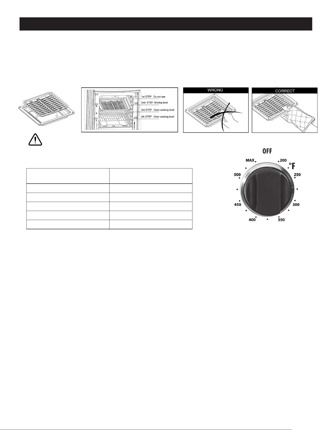
19
preheat for about 5 minutes with the door closed
• Place the food to be cooked above the broiling pan
• Place the broiling pan in the oven, The broiling pan should be placed above the shelf and it
should be centered with the broil burner.
ELECTRIC OVEN SETTING
Number printed on the
knob (temperature in ˚F)
Corresponding
temperature in ˚C
300 149
350 177
400 204
450 232
500 260
OVEN THERMOSTAT
- The numbers printed on the control panel indicate the increasing oven temperature valve (˚F)
- To regulate the temperature, set the chosen number onto the control knob indicator.
VERY IMPORTANT: The oven/broil shall be used always with the door closed.
VERY IMPORTANT: Never obstruct the oven vent slots on the backsplash.
Do not broil without using the broiling pan.
Important: Use always suitable protective gloves when inserting/removing the broiling pan,
shelves, pans on the cooking utensils from the oven.
Attention: the range becomes very hot during operation.
Attention: the oven door becomes very hot during operation, be sure to use the handle to
open/close.
Keep children away from the stove/oven when it is in use.
OPERATION OF OVEN (continued)
20
GENERAL RECOMMENDATION
WARNING
Electrical Shock Hazard
• Plug into a grounded 4-prong
outlet. Insure proper ground exists
before using the range.
• Do not remove ground prong.
• Do not use an adapter or extension
cord.
• Failure to follow these instructions
can result in death, re, or electrical shock.
CAUTION: Before any operation of cleaning and maintenance disconnect the
appliance from the electrical supply.
• It is advisable to clean when the appliance is cold and especially for cleaning the
enameled parts.
• Avoid leaving alkaline or acidic substances (lemon juice, vinegar, etc.) on the surfaces.
• Avoid using cleaning products with a chlorine or acidic base.
• The oven must always be cleaned after every use, using suitable products and keeping
in mind that its operation for 30 minutes on the highest temperature eliminates most
grime reducing it to ashes.
REPLACING THE OVEN LIGHT
• Let the oven cavity and broil burner cool down.
• Switch o the electric supply.
• Remove the protective cover.
• Unscrew and replace the bulb with a new one suitable for high temperature (300°~
570°F) having the same specifications: 240V 60Hz, 15W, E14.
• Replace the protective cover.
NOTE: Oven bulb replacement is not covered by your warranty.
LEVELING THE RANGE
The range must be level to obtain proper operating. The four screws type leveling legs
located on the corners at the bottom of range should be adjusted by turning them
clockwise to make the range higher or counter-clockwise to lower the range until the
range is level. Use a level on surface units to check the leveling of the range.
Electrical Shock Hazard
Plug into a grounded 4-prong outlet.
Do not remove ground prong.
Do not use an adapter.
Failure to follow these instructions can
result in death, re, or electrical shock.
WARNING
CARE & MAINTENANCE
21
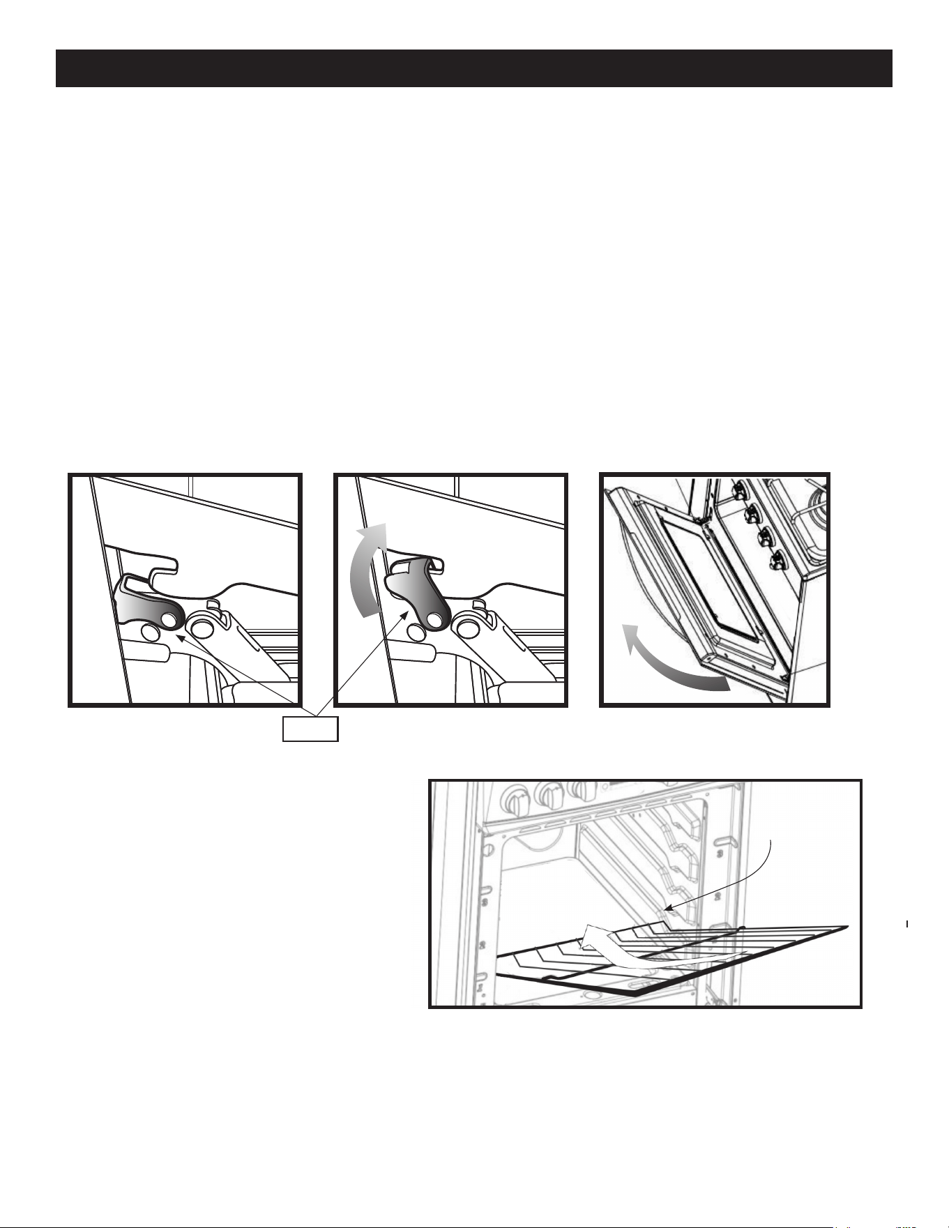
REMOVING THE OVEN DOOR FOR CLEANING
To facilitate oven cleaning, it is possible to remove the door. Please follow the
instructions carefully:
The oven door can easily be removed as follows:
• Open the door to fully.
• Lift the left and right hooks on the hinge figure (A,B).
• Hold the door as shown in figure (C) on a 45 degree angle.
• Gently close the door until the hooks touch the door, then lift at a 45 degree angle
• Set the door on a soft flat surface.
• To replace the door, repeat the above steps in reverse order.
OVEN RACK INSTALLATION AND
REMOVAL
• The oven racks are provided with
a safety catch to prevent accidental
removal
• They must be inserted as shown
• To pull them out remove the rack in
the reverse order
(C)(B)(A)
HOOK
SAFETY CATCH
CARE & MAINTENANCE (continued)
22
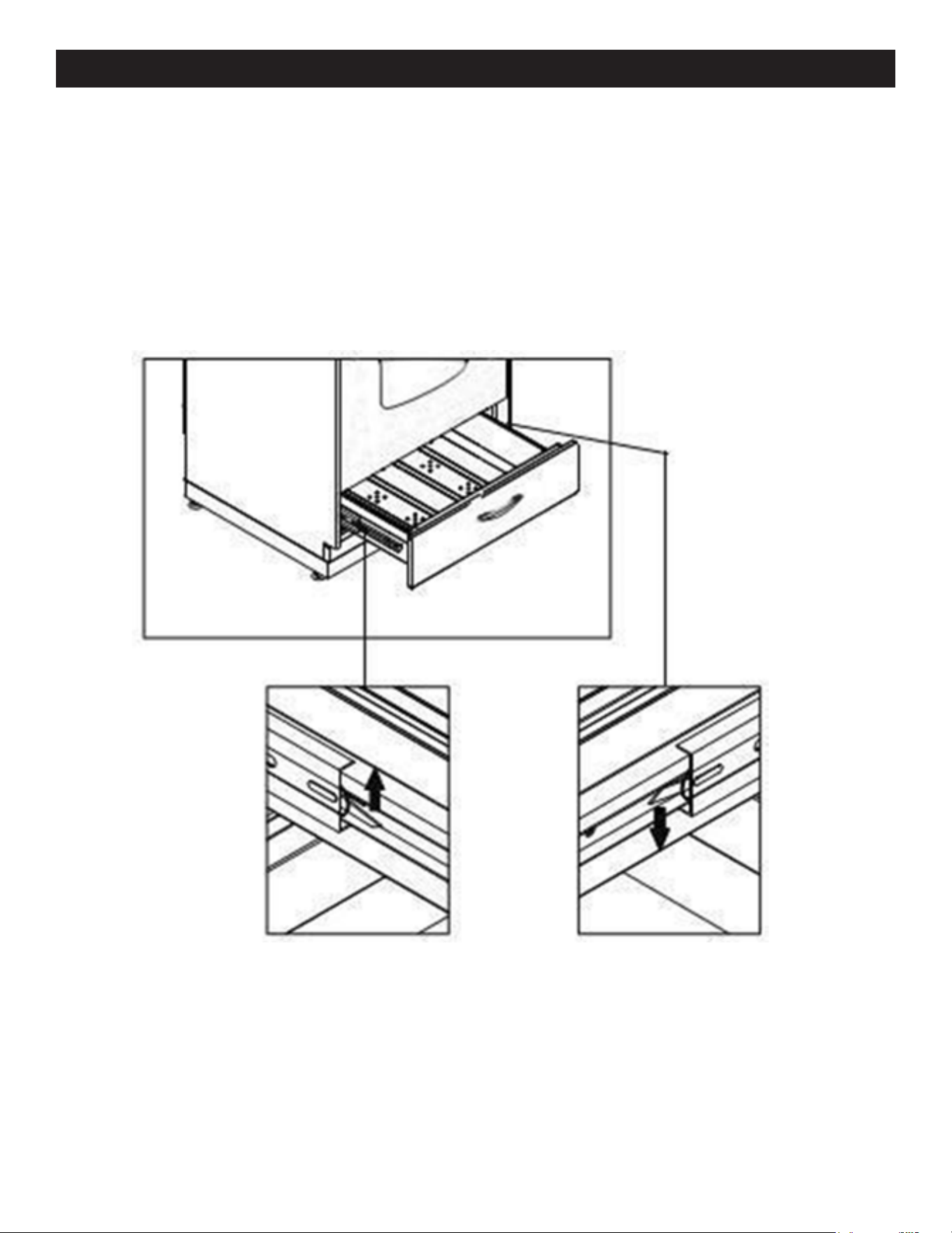
REMOVABLE STORAGE DRAWER
Lift the small hook to the left of the drawer upwards simultaneously pushing the right
hook downwards - see image
DO NOT STORE FLAMMABLE MATERIAL IN THE OVEN OR IN THE BOTTOM STORAGE
DRAWER
CARE & MAINTENANCE (continued)

23
Important: Before any operation of cleaning and maintenance disconnect the appliance from the
electrical supply.
It is advisable to clean when the appliance is cold and especially for cleaning the enameled parts.
Avoid leaving alkaline or acidic substances (lemon juice, vinegar, etc.) on the surfaces. Avoid using
cleaning products with a chlorine or acidic base.
The oven must always be cleaned after every use, using suitable products and keeping in mind
that its operation for 30 minutes on the highest temperature eliminates most grime reducing it to
ashes.
Always keep cleaning materials and chemicals in a safe place and away from children. Know what
you are using. Make sure all parts of the range are COOL before cleaning. Be sure to replace the
parts correctly.
Cooktop
Use a sponge and a commercial cooktop cleaner like Wisemen Cooktop Cleaner. for best
results. For heavier grease and residue a plastic scraper could be used along with this products
application instructions.
Knobs
Pull forward on the knobs to remove them. Wash in a water solution with a mild detergent mix. Do
not use an abrasive cleaner or any abrasive action. Abrasive action will scratch the knobs.
If the knobs become loose on the valve stem, spread the valve stem slightly with a small
screwdriver.
Using Commercial Oven Cleaners
Commercial oven cleaners may be used on porcelain lined ovens; however, many cleaners are very
strong, and it’s essential to follow instructions carefully. Be sure to wear rubber gloves to protect
your hands.
After using such cleaners, thoroughly rinse the oven with a solution of 1 tablespoon vinegar to 1
cup of water. Oven cleaners can coat or damage the thermostat sensing device (the long tube in
the oven) so that it will not respond to temperature accurately. If you use an oven cleaner, do not
let it contact the sensing bulb, or any chrome, aluminum, or plastic part of the range.
Do not apply or allow the cleaner to come in contact with any parts or surfaces other than
the oven interior.
Stainless Steel Elements
The stainless steel finish can be cleaned with detergent and warm water or a stainless steel
cleaner.
Stainless steel parts must be rinsed with water and dried with a soft and clean cloth or with a
chamois leather.
For dicult grime, use a commercially available, non-abrasive product for cleaning stainless
steel surfaces, or a little hot vinegar.
CLEANING THE RANGE

24
Aluminum Foil in Oven
WARNING
NEVER cover any slots, holes or passages in the oven bottom or cover an entire rack with
materials such as aluminum foil. Doing so blocks air flow through the oven. Aluminum foil
linings may also trap heat, causing a fire hazard.
Aluminium foil when used improperly is a cause of many range fires. Make certain that vents or
air openings aren’t covered by the foil. If the vents located along the sides of the oven bottom
are blocked, poor cooking will result.
Never cover a rack completely. A piece of foil slightly larger than the cookware can be placed on
the rack beneath the cookware.
Remove and discard aluminum foil after each use. This will help prevent grease and spilled food
from accumulating and becoming a fire hazard.
Cleaners and Cleaning Materials
Do not use harsh cleaners or de greasers on or around functional parts (valves, controls, etc., or
aluminum tubing). This will damage or drastically reduce the life of the part.
Use only a mild solution of soap and water on back guards, aluminum control panels and
painted surfaces. Never use harsh abrasives or cleaning powders that may scratch or mar the
surface. Make sure the cleaners and cleaning materials are suitable for use on the area to be
cleaned. Always keep cleaning materials in a safe place. Never use a sharp metal scraper to
clean glass, porcelain, or painted surfaces.
Repair Parts
When repair parts are needed, contact the dealer from whom the range was purchased. In case
your range was purchased from a source other than an appliance dealer, you may prefer to
contact the manufacturer at the address shown in this manual.
Moisture
During the initial heat-up of your range, the heat mixing with the cooler air in the oven cavity
may produce fogging of the door glass or a collection of water on the door. To prevent this,
open the oven door for the first few seconds of initial oven heat-up. This will allow the moist air
within the oven to escape, without the forming of visible moisture on the range. The amount of
moisture will depend upon the humidity of the air and water content of the food being cooked.
Fogging and even dripping water will usually occur in geographic locations of high humidity.
CLEANING THE RANGE (continued)

25
PROBLEM POSSIBLE CAUSE/FIXES
Surface units
will not maintain
a rolling boil or
frying rate is not
fast enough
You must use pans that are absolutely flat
Pan bottoms should closely match the diameter of the
surface unit selected
Foods cook
slowly
Improper cookware being used
Surface units do
not operate.
You have blown a household fuse or tripped a circuit
breaker
The surface units are not plugged in all the way
You have not set the control knobs correctly
Control knobs
will not turn
If it is a surface unit control knob, you are not pushing in
before turning
If it is the oven control knob you are trying to turn the
knob in the wrong direction
Oven light does
not work
Light bulb is loose or defective
Switch operating oven light is broken
Oven does not
work.
Is your rocker switch set to BROIL or in o position
You have blown a household fuse or tripped a circuit
breaker
You have not set the control knobs correctly
Broil does not
work
Is your rocker switch set to OVEN or in o position
You have blown a household fuse or tripped a circuit
breaker
Food does not
broil properly
The oven control knob is not set at Broil
Improper rack position being used
Cookware is not suited for broiling
Oven thermostat is defective
Food does not
bake properly
The oven control knob is not set properly
Rack position is incorrect
Incorrect cookware or cookware of improper size is being
used
Oven thermostat is defective
You can solve many common appliance problems saving you the cost of a possible
service call. Try the suggestions below before making the call to see if you can solve
the problem
TROUBLESHOOTING
26
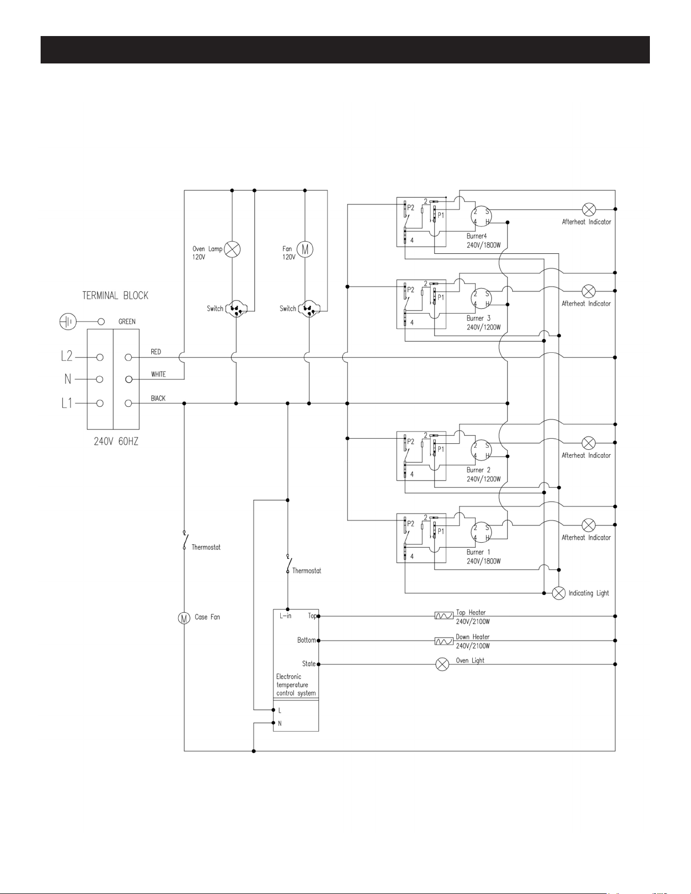
WIRING DIAGRAM
27
Please visit our website www.uniqueappliances.com to view a PDF
version of the schematics which will allow you to zoom in & out
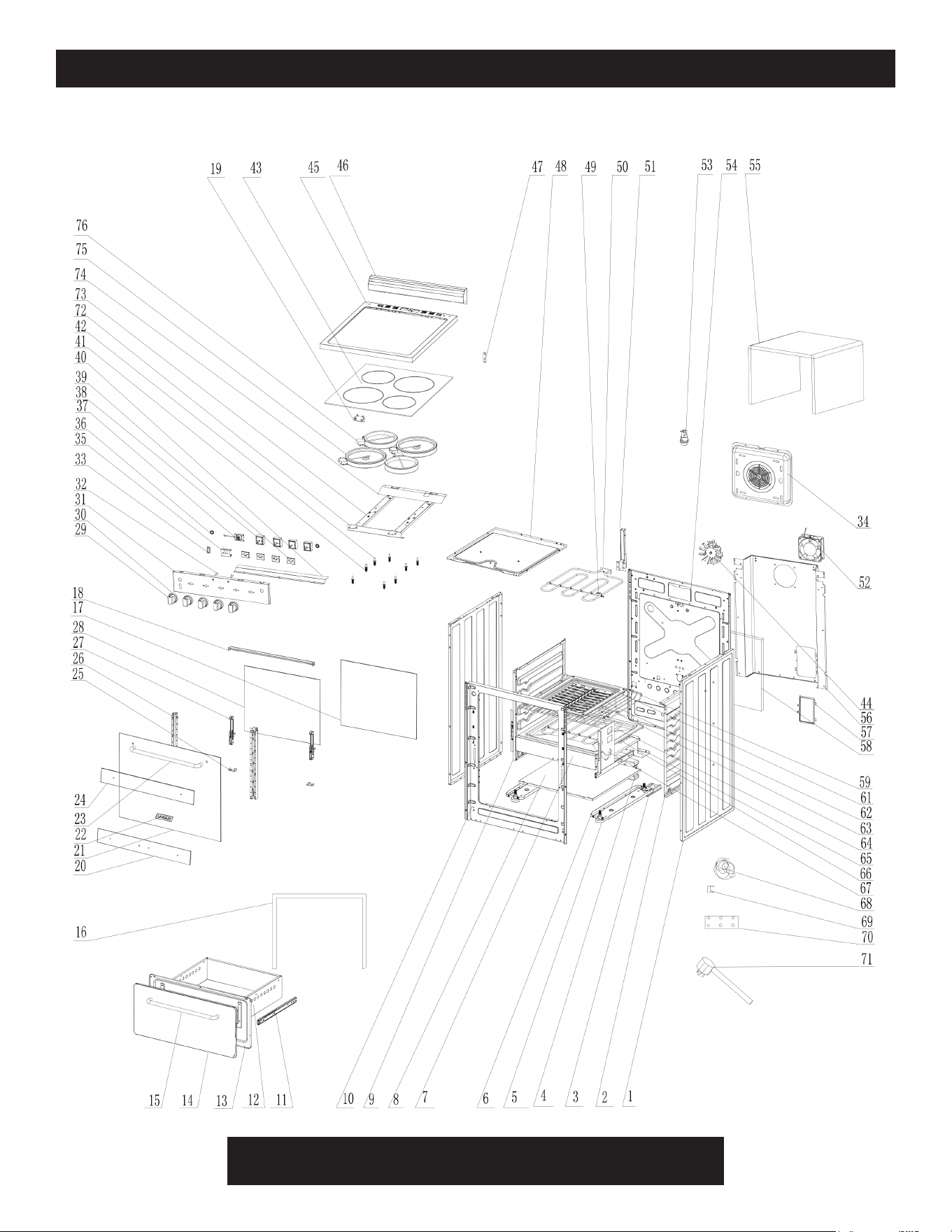
PARTS DIAGRAM & LIST
28
ITEM # PART # DESCRIPTION
UGP-G20C01-071002 Side Panel S/S (Left & Right) T=0.5 for UGP-24V; 20V PC1; EC S/S
UGP-G20C01-071002-01 Side Panel White (Left & Right) T=0.5 for UGP-24V; 20V PC1; EC W
UGP-G20C01-071002-02 Side Panel Black (Left & Right) T=0.5 for UGP-24V; 20V PC1; EC B
2
UGP-G20A01-070500 Cavity- Right Plate for UGP-24V; 20V PC1; EC S/S;W;B
3
UGP-G20A01-212500 Anti-tip Bracket for UGP-24V; 20V PC1; EC S/S;W;B
4
UGP-G20A01-210200 Weight Block (2.5 kg) for UGP-24V; 20V PC1; EC S/S;W;B
5
UGP-G20C01-071500 Oven Feet for UGP-24V; 20V PC1; EC S/S;W;B
6
UGP-G20A01-071100 Oven Feet Mounting Plate for UGP-24V; 20VPC1; EC S/S;W;B
7
UGP-G24A01-070200 Front Plate- Beam for UGP-24V PC1; EC S/S;W;B
8
UGP-G24C01-072101 Burner Mounting Plate for UGP-24V PC1; EC S/S;W;B
9
UGP-G20A01-070400 Cavity- Left Plate for UGP-24V; 20V PC1; EC S/S;W;B
10
UGP-G24C01-070102 Front Plate for UGP-24V PC1; EC S/S;W;B
11
UGP-G20A01-120700 Sliding Rail Component (set of 2) for UGP-24V; 20V PC1; EC S/S;W;B
12
UGP-G24C03-120500-02 Drawer Body for UGP-24V PC1; EC S/S;W;B
13
UGP-G24C02-120200-04 Drawer- S/S Inside Plate for UGP-24V PC1; EC S/S
UGP-G24H08-120100 Drawer- S/S Outside Plate for UGP-24V PC1; EC S/S
UGP-G24H08-120100-02 Drawer- Black Outside Plate for UGP-24V PC1; EC B
UGP-G24H08-120100-01 Drawer- White Outside Plate for UGP-24V PC1; EC W
15
UGP-G24B11-101900 Oven/Broiler Door Handle S/S for UGP-24V PC1; EC S/S;W;B
16
UGP-G24C01-071200 Cavity Sealing Strip-2 (long) for UGP-24V PC1; EC S/S;W;B
17
UGP-G24H08-100500 LOWE Inner Glass Door for UGP-24V PC1; EC S/S;W;B
18
UGP-G24B01-101401 Door Top Cover for UGP-24V PC1; EC S/S;W;B
19
UGP-E24H08-031000 Temperature indicator light for UGP-24V; 20V EC
20 N/A
21 N/A
22 N/A
23
UGP-G24B11-101900 Oven/Broiler Door Handle S/S for UGP-24V PC1; EC S/S;W;B
24 N/A
25
UGP-G20B01-100800 Door- Inside Glass Support (Left) for UGP-24V; 20V PC1: EC S/S;W;B
25
UGP-G20B01-100900 Door- Inside Glass Support (Right) for UGP-24V; 20VPC1; EC S/S;W;B
26
UPG-G20B01-101200 Hinge Support (Left) for UGP-24V; 20V PC1; EC S/S;W;B
26
UGP-G20B01-101300 Hinge Support (Right) for UGP-24V; 20V PC1; EC S/S;W;B
27
UGP-G20B01-110003 Door Hinge for UGP-24V PC1; EC S/S;W;B
28
UGP-G24H08-101100 LOWE Door Inside Window for UGP-24V PC1; EC S/S;W;B
29
UGP-G20A20-030100-09 Knob #20 short stem for UGP-24V; 20V EC S/S
30
UGP-G20A06-030200-10 Knob Ring #6 (Bezel) for UGP-24V; 20V PC1; EC S/S;W;B (set of 5)
31
UGP-E24H08-030300 Control Panel for UGP-24V PC1; EC S/S
32
UGP-E24F08-031002 Oven indicator light (blue) for UGP-24V; 20V EC S/S
33
UGP-E24H08-170200 Oven Option Switch for UGP-24V; 20V EC
34
UGP-G20H08-091700 Temperature Fan Cover for UGP-20V; 24V PC1; EC S/S;W;B
35
UGP-E24F08-190501 Rheostat mount bracket for UGP-24V; 20V EC
36
UGP-G24H08-170200 Fan Switch ASM for UGP-24V; 20V PC1; EC S/S;W;B
37
UGP-E24H08-030900 Oven Rheostat for UGP-24V; 20V EC
UGP-E20H08-030901 Main PCB for UGP-24V; 20V EC
UGP-E20H08-030902 Temperature Probe for UGP-24V; 20V EC
UGP-E20H08-030903 Oven Rheostat Connectin Wire for UGP-24V; 20V EC
UGP-E20H08-030904 Oven Option Switch Connecting Wire for UGP-24V; 20V EC
UGP-E20H08-030905 PCB Power In Harness for UGP-24V; 20V EC
UGP-E20H08-030906 Oven Control Wire for UGP-24V; 20V EC
UGP-E20H08-030907 Broiler Control Wire for UGP-24V; 20V EC
UGP-E20H08-030908 High Temperature Limit Connecting Wire for UGP-24V; 20V EC
38 UGP-E24F01-031600 Top Heating Element Rheostat for UGP-24V; 20V EC
39 UGP-E24H08-120900 Top Heating Element Rheostat mount bracket for UGP-24V; 20V EC
40 UGP-E24F08-214500 Control Panel Deflector for UGP-24V EC
41 UGP-E24F08-026100 Top Heating Element Support Spring for UGP-20V; 24V EC
1
14
not shown on drawing
PARTS DIAGRAM & LIST
29
42 UGP-E24F08-025100 Top Heating Element Support Bolt for UGP-20V; 24V EC
43 UGP-E24H08-030200 Microcrystalline Glass with Edging for UGP-24V EC
44 UGP-G20A01-091501 120 V Temperature Fan for UGP-20V; 24V PC1; EC S/S;W;B
45
UGP-E24F08-020100 N/A
46
UGP-G24H08-011500-Z Backsplash ASSY for UGP-24V EC
47
UGP-G20C01-022000 Cooktop Back Connection Plate for UGP-24V; 20V PC1; EC S/S;W;B
48
UGP-G24C01-070604 Cavity- Top Plate for UGP-24V EC S/S;W;B
49
UGP-C20A01-091201 Oven/Broiler Heating Element Support for UGP-20V; 24VEC S/S;W;B
50
UGP-E24F01-091001 Broiler Heating Element 240V 2100W for UGP-20V; 24V EC S/S;W;B
UGP-E24F01-074200 Chimney ASSY for UGP-20V; 24V EC S/S;W;B
UGP-E24F01-075000 N/A
52
UGP-E24F08-200900 Cooling Fan Motor for UGP-20V; 24V EC S/S;W;B
53
UGP-G20C01-180101 120V / 15W Oven Interior Light for UGP-24V; 20V PC1; EC S/S;W;B
54
UGP-G24C01-070307 Cavity- Back Panel for UGP-24V EC S/S;W;B
55
UGP-G24A01-070800 Cavity Heat Insulation Cotton for UGP-24V PC1; EC S/S:W;B
56
UGP-E24F01-072000 Back Panel for UGP-24V EC S/S;W;B
57
UGP-E24F08-072000 Service Door for UGP-20V; 24V EC S/S;W;B
58
UGP-E24F08-072900 Oven Insulation (back) for UGP-24V EC S/S;W;B
59 UGP-G24E05-070700 Broil Tray for UGP-24V PC1; EC S/S;W;B
61 UGP-G20C01-215100 Broil Grill for UGP-24V; 20V PC1; EC S/S;W;B
62 UGP-G20C01-215000 Broil Tray for UGP-24V; 20V PC1; EC S/S;W;B
63 UGP-G24H08-071900 Roasted Net (Oven Rack) for UGP-24V PC1; EC S/S;W;B
64 UGP-E20F01-091201 Oven Heating Element 240V 2100W for UGP-20V; 24V EC S/S;W;B
65 UGP-E24F01-034500 Wiring Block Bracket for UGP-24V EC S/S;W;B
66 UGP-E24F08-070700 Cavity- Bottom Panel (Oven Floor) for UGP-24V EC S/S;W;B
67 UGP-G20C01-111100 Door Hinge Plate for UGP-24V; 20V PC1; EC S/S;W;B
68 UGP-E24H08-180300 Harness for UGP-24V EC S/S;W;B
UGP-C36R05-076200 50C Temperature Limit Switch for UGP-24V; 20V EC S/S;W;B
UGP-E24F01-076200 240C Temperature Limit Switch for UGP-24V; 20V EC S/S;W;B
70
UGP-E20F01-106400 Oven Junction Box for UGP-24V; 20V EC S/S;W;B
71
UGP-G20A14-160100 Power Cord for UGP-24V; 20V EC S/S;W;B
72
UGP-E24F08-069900 Microcrystalline Glass Support (front) for UGP-24V EC
73
UGP-E24F08-024100 Top Heating Element Support Left for UGP-24V EC
73
UGP-E24F08-024200 Top Heating Element Support Right for UGP-24V EC
74
UGP-E24F08-022000 Microcrystalline Glass Support (rear) for UGP-24V EC
75
UGP-E24F08-022400 Top Heating Element 1800W for UGP-20V; 24V EC
76
UGP-E24F08-022300 Top Heating Element 1200W for UGP-20V; 24V EC
UGP-G24H08-100400S/S Oven door ASSY for UGP-24V PC1; EC S/S
UGP-G24H08-100400B Oven door ASSY for UGP-24V PC1; EC B
UGP-G24H08-100400W Oven door ASSY for UGP-24V PC1; EC W
51
69
ITEM # PART # DESCRIPTION
UGP-G20C01-071002 Side Panel S/S (Left & Right) T=0.5 for UGP-24V; 20V PC1; EC S/S
UGP-G20C01-071002-01 Side Panel White (Left & Right) T=0.5 for UGP-24V; 20V PC1; EC W
UGP-G20C01-071002-02 Side Panel Black (Left & Right) T=0.5 for UGP-24V; 20V PC1; EC B
2
UGP-G20A01-070500 Cavity- Right Plate for UGP-24V; 20V PC1; EC S/S;W;B
3
UGP-G20A01-212500 Anti-tip Bracket for UGP-24V; 20V PC1; EC S/S;W;B
4
UGP-G20A01-210200 Weight Block (2.5 kg) for UGP-24V; 20V PC1; EC S/S;W;B
5
UGP-G20C01-071500 Oven Feet for UGP-24V; 20V PC1; EC S/S;W;B
6
UGP-G20A01-071100 Oven Feet Mounting Plate for UGP-24V; 20VPC1; EC S/S;W;B
7
UGP-G24A01-070200 Front Plate- Beam for UGP-24V PC1; EC S/S;W;B
8
UGP-G24C01-072101 Burner Mounting Plate for UGP-24V PC1; EC S/S;W;B
9
UGP-G20A01-070400 Cavity- Left Plate for UGP-24V; 20V PC1; EC S/S;W;B
10
UGP-G24C01-070102 Front Plate for UGP-24V PC1; EC S/S;W;B
11
UGP-G20A01-120700 Sliding Rail Component (set of 2) for UGP-24V; 20V PC1; EC S/S;W;B
12
UGP-G24C03-120500-02 Drawer Body for UGP-24V PC1; EC S/S;W;B
13
UGP-G24C02-120200-04 Drawer- S/S Inside Plate for UGP-24V PC1; EC S/S
UGP-G24H08-120100 Drawer- S/S Outside Plate for UGP-24V PC1; EC S/S
UGP-G24H08-120100-02 Drawer- Black Outside Plate for UGP-24V PC1; EC B
UGP-G24H08-120100-01 Drawer- White Outside Plate for UGP-24V PC1; EC W
15
UGP-G24B11-101900 Oven/Broiler Door Handle S/S for UGP-24V PC1; EC S/S;W;B
16
UGP-G24C01-071200 Cavity Sealing Strip-2 (long) for UGP-24V PC1; EC S/S;W;B
17
UGP-G24H08-100500 LOWE Inner Glass Door for UGP-24V PC1; EC S/S;W;B
18
UGP-G24B01-101401 Door Top Cover for UGP-24V PC1; EC S/S;W;B
19
UGP-E24H08-031000 Temperature indicator light for UGP-24V; 20V EC
20 N/A
21 N/A
22 N/A
23
UGP-G24B11-101900 Oven/Broiler Door Handle S/S for UGP-24V PC1; EC S/S;W;B
24 N/A
25
UGP-G20B01-100800 Door- Inside Glass Support (Left) for UGP-24V; 20V PC1: EC S/S;W;B
25
UGP-G20B01-100900 Door- Inside Glass Support (Right) for UGP-24V; 20VPC1; EC S/S;W;B
26
UPG-G20B01-101200 Hinge Support (Left) for UGP-24V; 20V PC1; EC S/S;W;B
26
UGP-G20B01-101300 Hinge Support (Right) for UGP-24V; 20V PC1; EC S/S;W;B
27
UGP-G20B01-110003 Door Hinge for UGP-24V PC1; EC S/S;W;B
28
UGP-G24H08-101100 LOWE Door Inside Window for UGP-24V PC1; EC S/S;W;B
29
UGP-G20A20-030100-09 Knob #20 short stem for UGP-24V; 20V EC S/S
30
UGP-G20A06-030200-10 Knob Ring #6 (Bezel) for UGP-24V; 20V PC1; EC S/S;W;B (set of 5)
31
UGP-E24H08-030300 Control Panel for UGP-24V PC1; EC S/S
32
UGP-E24F08-031002 Oven indicator light (blue) for UGP-24V; 20V EC S/S
33
UGP-E24H08-170200 Oven Option Switch for UGP-24V; 20V EC
34
UGP-G20H08-091700 Temperature Fan Cover for UGP-20V; 24V PC1; EC S/S;W;B
35
UGP-E24F08-190501 Rheostat mount bracket for UGP-24V; 20V EC
36
UGP-G24H08-170200 Fan Switch ASM for UGP-24V; 20V PC1; EC S/S;W;B
37
UGP-E24H08-030900 Oven Rheostat for UGP-24V; 20V EC
UGP-E20H08-030901 Main PCB for UGP-24V; 20V EC
UGP-E20H08-030902 Temperature Probe for UGP-24V; 20V EC
UGP-E20H08-030903 Oven Rheostat Connectin Wire for UGP-24V; 20V EC
UGP-E20H08-030904 Oven Option Switch Connecting Wire for UGP-24V; 20V EC
UGP-E20H08-030905 PCB Power In Harness for UGP-24V; 20V EC
UGP-E20H08-030906 Oven Control Wire for UGP-24V; 20V EC
UGP-E20H08-030907 Broiler Control Wire for UGP-24V; 20V EC
UGP-E20H08-030908 High Temperature Limit Connecting Wire for UGP-24V; 20V EC
38 UGP-E24F01-031600 Top Heating Element Rheostat for UGP-24V; 20V EC
39 UGP-E24H08-120900 Top Heating Element Rheostat mount bracket for UGP-24V; 20V EC
40 UGP-E24F08-214500 Control Panel Deflector for UGP-24V EC
41 UGP-E24F08-026100 Top Heating Element Support Spring for UGP-20V; 24V EC
1
14
not shown on drawing
PARTS DIAGRAM & LIST (continued)
30
RATING LABEL
5013515
WARNING / ATTENTION
Do not store flammable materials inside this drawer
Ne Pas entreposer de matériaux inflammables à L'Intérieur
de ce tiroir
MODEL / MODÈLE : UGP-24V EC
SERIAL NO / N°DE SÉRIE :
RATED VOLTAGE / TENSION NOMINALE :
240V
RATED POWER / PUISSANCE NOMINALE : 8.1KW
RATED FREQUENCY / RATED FREQUENCY : 60Hz
© Unique Appliances Ltd. All rights reserved.
Designed and manufactured for: Unique Appliances Ltd.
2245 Wyecroft Road #5, Oakville, Ontario, Canada, L6L 5L7
© Unique Appliances Ltd. Tous droits réservés.
Conçu et fabriqué pour: Unique Appliances Ltd.
2245 Wyecroft Road #5, Oakville, Ontario, Canada, L6L 5L7
www.UniqueAppliances.com
MADE IN CHINA
FABRIQUÉ EN CHINE
CONFORMS WITH UL STD. 858
CERTIFIED TO CSA STD C22.2 NO.61
EN CONFORMITÉ AVEC UL STD. 858
CERTIFIÉS CSA STD C22.2 NO.61
120 mm

31
Unique Appliances Ltd. (hereafter “Unique”) warrants that this UNIQUE appliance is free from manufacturer’s
defects in material and workmanship under normal usage and service under the following terms.
Parts Warranty
This appliance has been designed for domestic household use. If properly installed, adjusted and operated under
normal conditions in accordance with printed instructions, it will satisfactorily perform the functions that are
generally expected of this type of appliance.
If the appliance fails to do so because of a defect in material or workmanship within one year from the original date of purchase:
Unique will at our option, repair, exchange, or correct by other means Unique consider appropriate, any part(s) Unique finds to
be defective except for the surface finish.
Ownership
This Warranty is made only to the first purchaser (”original purchaser”) who acquires this appliance for his/her own use and will
be honored by Unique Appliances and by the Seller. Purchaser must retain their receipt as proof of purchase date.
Warranty Conditions
This warranty does not apply to any appliance that has been subjected to alterations, misuse, abuse (including damage by
foreign agents or chemicals), accident, improper installation or service, delivery damage, or other than normal household use
and service. This UNIQUE appliance must be serviced regularly as outlined in the Owner’s Manual. In case of damage, the owner
must provide proof of purchase, Model, and Serial Number to the selling dealer or Unique Appliances. This warranty is LIMITED
STRICTLY to the terms indicated herein, and no other expressed warranties or remedies thereunder shall be binding on Unique.
Purchaser’s Responsibilities
The purchaser will be responsible for the costs of any service calls requested to demonstrate or confirm the proper operation
of the appliance, the installation, or to correct malfunctions in the appearance created by the operation of the appliance in a
manner not prescribed by or cautioned against in the use and care instructions.
Model and Serial Number
The appliance model number and serial number can be found on a rating plate on the range. The purchaser should always refer
to the model and serial number when talking to or contacting the dealer from whom the appliance was purchased.
EXCLUSIONS
Save as herein provided, by Unique, there are no other warranties, conditions, representations or guarantees, express or implied,
made or intended by Unique or its authorized distributors and all other warranties, conditions, representations or guarantees,
including any warranties, conditions, representations or guarantees under any Sale of Goods Act or like legislation or statute is
hereby expressly excluded. Save as herein provided, Unique shall not be responsible for any damages to persons or property,
including the unit itself, howsoever caused or any consequential damages arising from the malfunction of the unit and by the
purchase of the unit, the purchaser does hereby agree to indemnify and hold harmless Unique from any claim for damages to
persons or property caused by the unit
Removal or disfigurement of the rating plate will void the warranty. The purchaser will be responsible for any expenses involved
in making the gas range readily accessible for servicing. The purchaser will be responsible for any extra charges where the
installation is in a remote location such as un-assumed roads, islands, areas known as cottage country, more than 20 Km outside
a Metropolitan area, or where a technician is not available. Freight damage is not covered by this warranty.
GENERAL PROVISIONS
No warranty or insurance herein contained or set out shall apply when damage or repair is caused by any of the following:
1) Power failure.
2) Damage in transit or when moving the appliance.
3) Improper power supply such as low voltage, defective house wiring or inadequate fuses.
4) Accident, alteration, abuse or misuse of the appliance such as inadequate air circulation in the room or abnormal operating
conditions (ie. extremely high or low room temperature).
5) Use for commercial or industrial purposes (ie. If the appliance is not installed in a domestic residence).
6) Fire, water damage, theft, war, riot, hostility, acts of God such as hurricanes, floods etc.
7) Service calls resulting in customer education.
8) Improper Installation (ie. Building-in of a free standing appliance or using an appliance outdoors that is not approved for
outdoor application, including but not limited to: garages, patios, porches or anywhere that is not properly insulated or
climate controlled).
Proof of purchase date will be required for warranty claims; retain bills of sale. In the event that warranty service is required,
present the proof of purchase to our authorized service depot.
Nothing within this warranty shall imply that Unique will be responsible or liable for any direct or indirect loss of foods
caused by failure in operation.
Factory Assistance
If the purchaser is unable to locate an authorized dealer/service agent, or if the purchaser does not receive satisfaction from the
dealer, they may contact Unique Appliances Customer Service directly at Toll Free 1-877-427-2266 or 905-827-6154.
WARRANTY

32
For questions related to the operation, safety or the purchase of your fridge, please contact your
dealer for more information. For general information, contact our customer service department:
NOTES
APPLIANCE INFORMATION
(manual copy - keep with your records)
To make care and servicing of your fridge easy and ecient, please record the following informa-
tion for future reference:
Model:
Serial Number:
Purchased From:
Date Purchased:
APPLIANCE INFORMATION
CONTACT US
Toll-free
1-877-427-2266 or 1-905-827-6154
(available during regular business
hours, 8:30 am to 4:30 pm, EST.
Website
www.uniqueappliances.com
Email
info@UniqueAppliances.com
Please visit our website at https://uniqueappliances.com/product-registration/
to register your product.
PRODUCT REGISTRATION

©2021 Unique Appliances Ltd., 2245 Wyecroft Road #5,
Oakville, Ontario, Canada, L6L 5L7
www.UniqueAppliances.com