OWNER’S GUIDE
serial number:
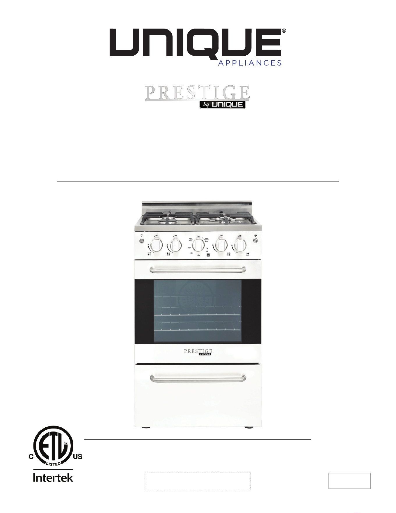
PRESTIGE GAS RANGE
20” (50.8 cm) CONVECTION GAS RANGE
(NG & LPG CONVERTIBLE)
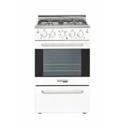
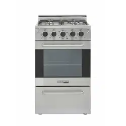
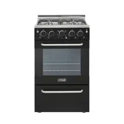
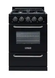
MODEL NUMBERS: UGP-20V PC1 S/S, UGP-20V PC1 W, UGP-20V PC1 B
4009900
NOV20V3
PRESTIGE GAS RANGE 20” (50.8 CM) CONVECTION GAS RANGE
(NG & LPG CONVERTIBLE)
READ AND SAVE THESE INSTRUCTIONS
Have the dealer where you purchase your new range install it or have him recommend
a qualified installer. Installation must conform with local codes. In the absence of local
codes, the installation must conform with the National Fuel Gas Code, ANSI Z223.
1-Latest Edition in the U.S.A. or the CAN/CGA B149.1 or .2 Installation Codes in Canada.
Read and save these instructions
Installation & Owner’s Manual
This manual contains information for:
• Important Safeguards
• Installation
• Use and Care
Important
TO THE OWNER OF THE RANGE: Retain this owner’s manual for future reference.
TO THE INSTALLER: Leave this owner’s manual with the range.
Certain ranges come equipped with special features. Determine from a study of your
range which of the instructions given in this booklet pertain to your range.
This booklet gives valuable instructions covering the installation, adjustment and use of
your range.
How to Obtain Service and/or Parts
When your range does not operate in accordance with the instructions in the manual,
you should contact the dealer in your immediate vicinity for service. Or, the purchaser
may contact the service organization noted on the warranty.
MANUFACTURED & CERTIFIED BY
Unique Appliances
2245 Wyecroft Road #5, Oakville, Ontario, Canada L6L 5L7
Phone: 905-827-6154 Toll Free: 1-877-427-2266 Fax: 905-827-2027
www.UniqueAppliances.com
WARNING: If the information in this manual is not followed exactly, a fi re or explosion
may result causing property damage, personal injury or death.
– Do not store or use gasoline or other fl ammable vapors and liquids in the vicinity of this
or any other appliance.
– WHAT TO DO IF YOU SMELL GAS
• Do not try to light any appliance.
• Do not touch any electrical switch.
• Do not use any phone in your building.
• Immediately call your gas supplier from a neighbor’s phone. Follow the gas supplier’s
instructions.
• If you cannot reach your gas supplier, call the fi re department.
– Installation and service must be performed by a qualifi ed installer, service agency or the
gas supplier.
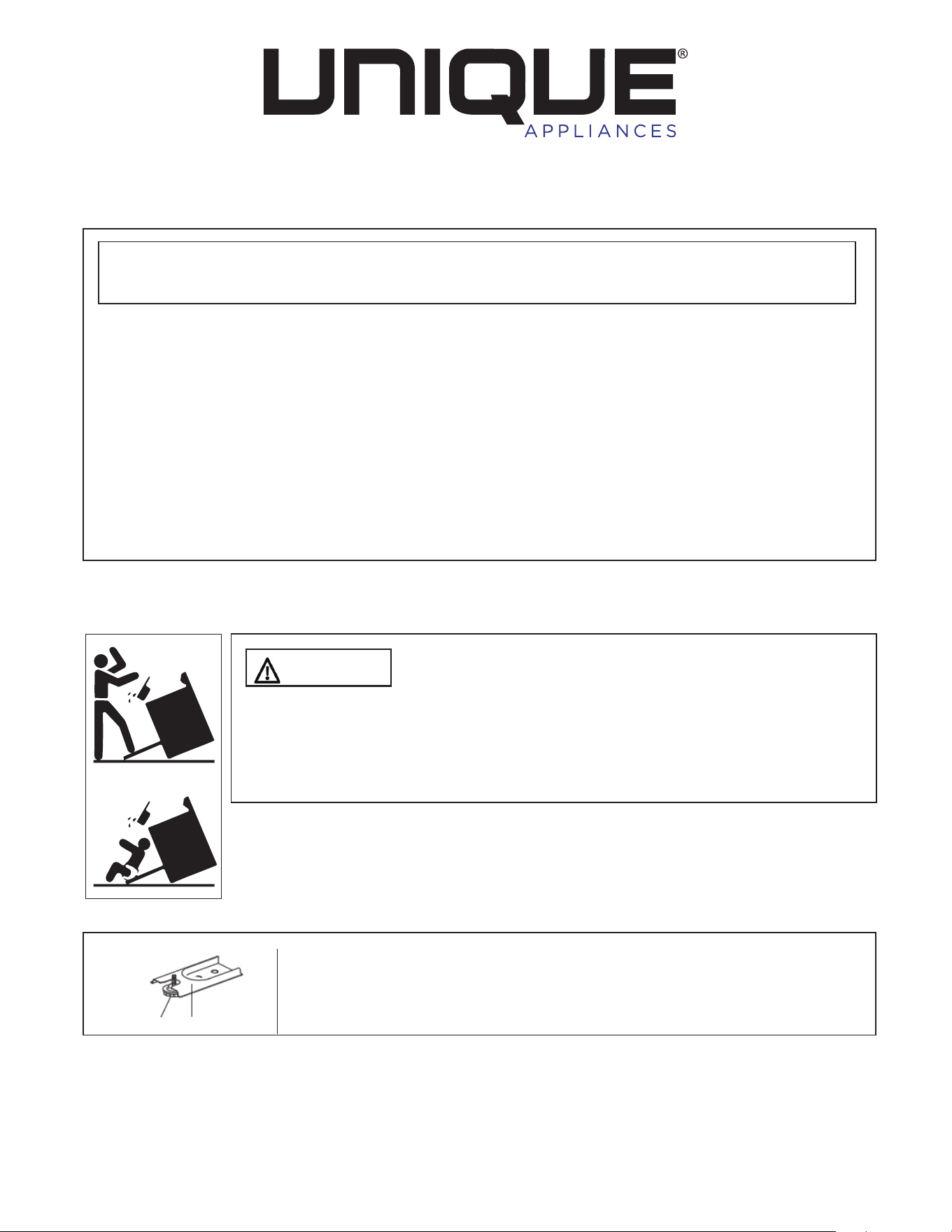
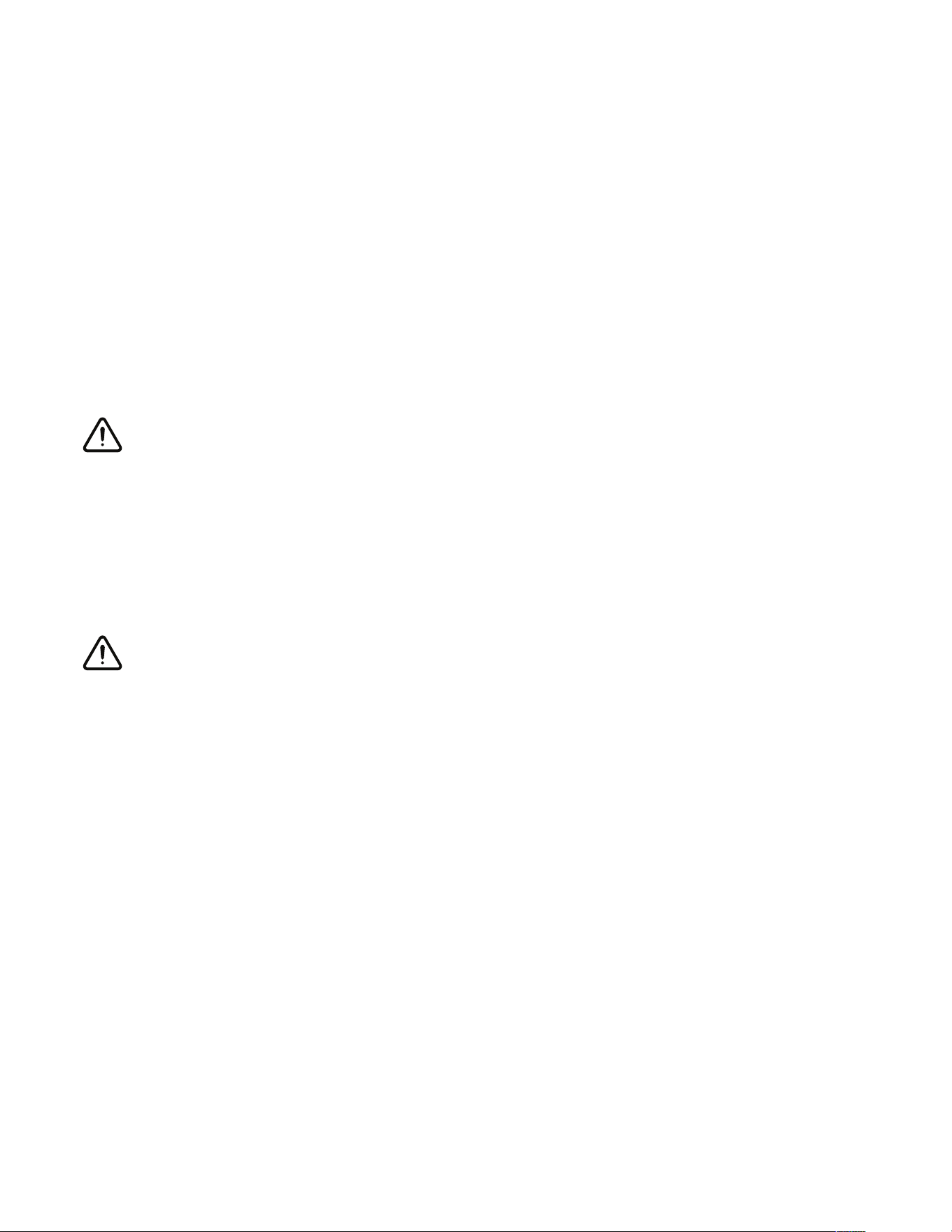
WARNING
To reduce the risk of tipping the appliance by abnormal
usage or improper door loading, the appliance must be secured by
properly installing the Anti-Tip device packed with the appliance. To
check if the device is installed and engaged properly. Carefully tip the
range forward. The Anti-Tip device should engage and prevent the range
from tipping over.
If this range is removed for any reason, service or cleaning, etc., it must
be replaced as outlined in the installation instructions before placing the
range back in operation.
Making sure the anti-tip bracket is installed:
• Slide range forward.
• Look for the anti-tip bracket securely attached to fl oor.
• Slide range back so rear range foot is under anti-tip bracket.
X2
Range Foot Anti-tip Bracket

4
IMPORTANT SAFEGUARDS . . . . . . . . . . . . . . . . . . . . . . . . . . . . 7
CARBON MONOXIDE WARNING . . . . . . . . . . . . . . . . . . . . . . . . . . 13
ENERGY SAVING IDEAS . . . . . . . . . . . . . . . . . . . . . . . . . . . . . . 14
INSTALLATION INSTRUCTIONS . . . . . . . . . . . . . . . . . . . . . . . . . . 15
HOW TO INSTALL THE BACKSPLASH . . . . . . . . . . . . . . . . . . . . . . . 16
GAS CONNECTION . . . . . . . . . . . . . . . . . . . . . . . . . . . . . . . . . 17
WALL CLEARANCES & ANTI-TIP LOCATION . . . . . . . . . . . . . . . . . 20
NG CONVERSION INSTRUCTIONS . . . . . . . . . . . . . . . . . . . . . . . 22
CHECKING FOR MANIFOLD GAS PRESSURE . . . . . . . . . . . . . . . . . 26
ADJUSTING THE TOP BURNER AND OVEN FLAME . . . . . . . . . . . . . . 27
OPERATION OF RANGE . . . . . . . . . . . . . . . . . . . . . . . . . . . . . 30
BROILING . . . . . . . . . . . . . . . . . . . . . . . . . . . . . . . . . . . . . . 35
CLEANING THE RANGE . . . . . . . . . . . . . . . . . . . . . . . . . . . . . 36
CARE AND MAINTENANCE. . . . . . . . . . . . . . . . . . . . . . . . . . . . 40
TROUBLESHOOTING GUIDE . . . . . . . . . . . . . . . . . . . . . . . . . . . 42
WIRING DIAGRAM . . . . . . . . . . . . . . . . . . . . . . . . . . . . . . . . . 44
PARTS DIAGRAM AND LIST. . . . . . . . . . . . . . . . . . . . . . . . . . . . 45
WARRANTY . . . . . . . . . . . . . . . . . . . . . . . . . . . . . . . . . . . . 50
PRODUCT REGISTRATION . . . . . . . . . . . . . . . . . . . . . . . . . . . . . 51
CONTACT US . . . . . . . . . . . . . . . . . . . . . . . . . . . . . . . . . . . . . 51
TABLE OF CONTENTS
5
BEFORE USING YOUR GAS RANGE
WARNING
HAVE THIS RANGE INSTALLED BY A QUALIFIED INSTALLER.
Improper installation, adjustment, alteration, services, or maintenance can cause injury or
property damage. Consult a qualified installer, service agency, or the gas supplier.
BEFORE USING YOUR GAS RANGE:
• Remove the exterior and interior packing.
• Remove the protective film on steel and aluminum parts.
• Check to be sure you have all of the parts listed below.
• 1 backsplash
• LP gas conversion packet (injectors for LP gas, 6pcs)
• 2 anti-tip brackets
• 2 pan supports
• 2 oven racks
• 4 caps and bases in the burner assembly
• 1 broiler grid
• 1 broiler tray
• 1 regulator (pre-installed)
• 5 screws for backsplash
• 1 instruction/installation manual
• Clean the interior surface with lukewarm water using a soft cloth
• Have the installer show you the location of the range’s gas shut-o valve and how to shut it
o if necessary.
• Have your range installed and properly grounded by a qualified installer in accordance with
the installation instructions.
• Do not attempt to repair or replace any part of your range unless it is specifically
recommended in this manual.
• Be sure your range is correctly adjusted by a qualified service technician or installer for the
type of gas (natural or LP) that is being used.
• Do not remove permanently axed labels, warnings, or plates from the unit. This may void
the warranty.
• The installer should leave these instructions with the consumer who should retain for local
inspector’s use and for future reference.
• Please observe all local and national codes and ordinances.

6
WELCOME & CONGRATULATIONS
Congratulations on your purchase of a UNIQUE range! We are very proud of our product – and
are completely committed to providing you with the best service possible. Your satisfaction is
our #1 priority. Please read this manual very carefully. It contains valuable information on how to
properly maintain your new Unique propane range.
We know you will enjoy your new range and Thank You for choosing one of our Unique
Appliances!. We hope you will consider us for future purchases.
PLEASE READ AND SAVE THESE INSTRUCTIONS
This manual provides specific operation instructions for your model. Use your range only as
instructed in this manual. These instructions are not meant to cover every possible condition
and situation that may occur. Common sense and caution must be practiced when installing,
operating and maintaining the appliance.
Record in the space provided below the Model No. and Serial No. of this appliance.
These numbers are found on the serial plate located at the bottom drawer.
Model No. ______________________
Serial No. ________________________
Purchase Date ________________________
Record these numbers for future use.
IMPORTANT: Keep a copy of your bill of sale. The date on the bill establishes the warranty
period should service be required. If service is performed, it is in your best interest to obtain
and keep all receipts.
PLEASE DO THIS NOW!
Please visit our website at https://UniqueAppliances.com/product-registration/ to register
your product.
7
READ ALL IMPORTANT SAFEGUARDS AND
ALL INSTRUCTIONS BEFORE USING THE APPLIANCE.
IF YOU SMELL GAS:
• Open windows
• Don’t touch electrical switches
• Extinguish any open flame
• Immediately call your gas supplier
FOR YOUR SAFETY:
• Keep appliance area clear and free from combustible materials gasoline and other
flammable vapors and liquids.
WARNINGS
Destroy the carton and plastic bags after the range is unpacked. Children should not use
packaging material for play. Cartons covered with rugs, bedspreads, or plastic sheets can become
airtight chambers. Remove all staples from the carton. Staples can cause severe cuts and destroy
finishes if they come in contact with other appliances or furniture.
Be safety conscious. The preparation of food in an oven requires temperatures that
could cause severe burns. Before using this new appliance, carefully read and follow all
instructions.
WARNING
The California Safe Drinking Water and Toxic Enforcement Act of 1986 (Proposition 65)
requires the Governor of California to publish a list of substances known to the State of
California to cause cancer or reproductive harm. In addition, businesses must warn customers
of potential exposure to such substances.
Users of this appliance are hereby warned that the burning of gas can result in low-level
exposure to some of the listed substances, including formaldehyde, benzene, soot and carbon
monoxide. This is caused primarily from the incomplete combustion of natural gas or LP fuel.
Properly adjusted burners will minimize incomplete combustion. Exposure to these
substances can also be minimized by properly venting the burners by opening a window or
using a ventilating hood or fan.

8
Notice: Never keep pet birds in the kitchen. Birds have a very sensitive respiratory system.
Fumes released from cooking oil, fat, margarine or overheated non-stick cookware may be
harmful or fatal to birds.
PROPER INSTALLATION: Be sure a qualified technician in accordance with the National Fuel
Gas Code ANSI Z223.1/NFPA54 properly installs your appliance. Install only per installation
instructions provided in the literature package for this range. Be sure leveling legs are in place
at the bottom corners of the range. If necessary, raise or lower the leveling legs at the base of
the range by turning clockwise or counter clockwise to insure a level range.
Ask your dealer to recommend a qualified technician and an authorized repair service. Have the
technician familiarize you with the locations of the manual gas shut o valve and gas meter in
the event it is necessary to shut o gas supply to the unit during an emergency.
The following situations may cause serious bodily harm, death or property damage.
TO REDUCE THE RISK OF TIPPING OF THE RANGE, THE RANGE MUST BE SECURED BY A
PROPERLY INSTALLED ANTI-TIP BRACKET PROVIDED WITH THE RANGE. TO CHECK IF THE
DEVICE IS INSTALLED AND ENGAGED PROPERLY, CAREFULLY TIP THE RANGE FORWARD.
THE ANTI-TIP DEVICE SHOULD ENGAGE AND PREVENT THE RANGE FROM TIPPING OVER.
REFER TO THE INSTALLATION INSTRUCTIONS PACKAGED WITH THE ANTI-TIP BRACKET
FOR PROPER ANTI-TIP BRACKET INSTALLATION.
• Never leave children alone or unattended in the area where an appliance is in use. They
should never be allowed to sit or stand on any part of the appliance. Never leave the oven
door open when the range is unattended.
• Do not store items of interest to children in the cabinets above a range or on the
backguard of a range. Children climbing on the range to reach the items could be seriously
injured.
Do not allow children to climb or play around the range. The weight of a child on an open
oven door may cause the range to tip, resulting in serious burns or other injury.
IMPORTANT: Observe all governing codes and ordinances. Do not obstruct flow of combustion
and ventilation air.
9
USER SERVICING: Do not repair or replace any part of the appliance unless specifically
recommended in this owner’s guide. Only a qualified technician should do all other servicing.
This will reduce the risk of personal injury and damage to the range.
Storage in or on appliance: Flammable materials should not be stored in an oven, near
surface burners or in the broiler section. This includes paper, plastic and cloth items, such as
cookbooks, plastic ware and towels, as well as flammable liquids. Do not use the oven for
storage. Do not store explosives, such as aerosol cans, on or near the range.
Remove the oven door from any unused range if it is to be stored or discarded.
Stepping, leaning or sitting on the doors or broiler section of this range can result in serious
injuries and cause damage to the range.
The following situations could cause bodily injury or property damage.
DO NOT TOUCH SURFACE BURNERS, AREAS NEAR THESE BURNERS, OVEN BURNERS
OR INTERIOR SURFACES OF THE OVEN. Both surface burners and oven burners may be hot
even though the flame is not visible. Areas near surface burners may become hot enough to
cause burns. During and after use, do not touch, or let clothing or other flammable materials
touch these areas until they have had sucient time to cool. Among these areas are the range,
surfaces facing the range, the oven vent openings and surfaces near these openings, oven door
and windows.
NEVER use this appliance as a space heater to heat or warm the room. Doing so may
result in carbon monoxide poisoning and overheating of the oven.
Wear proper apparel. Loose fitting or hanging garments should never be worn while using the
appliance. Do not let clothing or other flammable materials contact surface burners or interior
surfaces of the oven until they have had sucient time to cool.
Never modify or alter the construction of the range. Do not remove leveling legs, panels, wire
covers, anti-tip brackets or any other permanent part of the product.
When heating fat or grease, watch it closely. Fat or grease may catch fire if allowed to
become too hot.
10
Do not use water or flour on grease fires. Smother the fire with a pan lid, baking soda or use
a dry chemical or foam-type extinguisher.
Operation of the Surface Burners. When the burners are operated for the first time, a small
amount of smoke may be generated due to tape residue or manufacturing lubrication, this is
not dangerous. Operate the burners for about five minutes to rid the burners of this material
before cooking.
Use only dry potholders. Wet or damp potholders on hot surfaces could result in burns from
steam. Do not let the potholder touch hot heating areas. Do not use a towel or other bulky
cloth instead of a potholder.
Use proper flame size. Adjust flame size so it does not extend beyond the edge of the
cookware. The use of undersized cookware will expose a portion of the burner flame and may
result in severe burns or direct contact and ignition of clothing. Also, proper relationship of
cookware to burner will improve eciency.
NEVER cover any slots, holes or passages in the oven bottom or cover an entire rack
with materials such as aluminum foil. Doing so blocks air flow through the oven and
may cause carbon monoxide poisoning. Aluminum foil linings may also trap heat,
causing a fire hazard. Refer to the cleaning section of this manual for more information on the
use of aluminum foil.
Placement of oven racks: Always place an oven rack in the desired location while the oven is
cool. If a rack must be moved when the oven is hot, use potholders and grasp the rack with
both hands to reposition. Do not let potholders contact hot oven walls. Remove all cookware
from the rack before moving.
Do not heat unopened food containers. Build-up of pressure may cause the container to
burst and result in injury.
Keep the oven vent duct unobstructed. The oven vent is located along the bottom of the
back guard. Touching the surfaces in the vent area when the oven is being operated may
cause severe burns. Also, do not place plastic or heat-sensitive items on or near the oven
vents. These items could melt or ignite. The range requires fresh air for proper burner
combustion. Do not block the flow of air around the base or beneath the lower front panel of
the range.
Use care when opening oven door: Stand to the side of the oven when opening the oven
door. Slowly open the door to allow hot air or steam to escape before removing or replacing
food.
Know which knob controls each burner. Place a pan of food on the burner before turning
it on, and turn the burner o before removing the pan. Always turn to the full position when
igniting top burners. Then adjust the flame size so it does not extend beyond the edge of the
cookware.

11
Cookware handles should be turned inward and not extend over adjacent surface burners.
To reduce the risk of burns, ignition of flammable materials, and spillage due to unintentional
contact with the cookware, the handle of a cookware should be positioned so that it is turned
inward, and does not extend over adjacent surface burners.
Never leave the surface burners unattended. Boilovers may cause smoking, greasy spill-
overs may catch fire or a pan which has boiled dry may melt.
Do not place hands between the spring tension hinge and the oven door frame when you
are removing the oven door. You could pinch your fingers.
Allow parts to cool to room temperature before touching or removing them from the
range. When a surface burner is first turned o, the burner and grate are hot enough to cause
burns.
Clean the range regularly to keep all parts free of fat or grease, which could catch fire. Pay
particular attention to the area underneath each surface burner. Exhaust fan ventilating hoods
and grease filters should be clean. Do not allow fat or grease to accumulate. Greasy deposits
in the fan could catch fire. Refer to the hood manufacturer’s instructions for cleaning.
Do not use a “cyclonic” range hood with this product. Some range hoods circulate air by
blowing downward toward the range top then drawing the air back up into the hood. This
creates a “cyclonic” air wash that is designed for electric ranges only. A “cyclonic” hood may
cause the burners of a gas range to operate improperly.
Glazed cookware: Only certain types of glass, glass/ceramic, ceramic, earthenware, or other
glazed cookware are suitable for rangetop service without breaking, due to the sudden
change in temperature. Check the manufacturer’s recommendations for rangetop use.
Do not place plastic salt and pepper shakers, spoon holders or plastic wrappings on top
of the range. These items could melt or ignite. Potholders, towels or wooden spoons could
catch fire if placed too close to the flame.
Do not use a wok equipped with a metal ring that extends beyond the burner. Because
this ring traps heat, the burner and grate could be damaged. Also, the burner may not work
properly, creating a carbon monoxide level above current health standards.
Do not clean the oven door gasket. The door gasket is essential for a good seal. Care should
be taken not to rub, damage or move the gasket.
12
Flexible Connectors: If the gas range/oven is connected to a gas supply with a metal flexible
connector, move the range/oven with CAUTION for service or cleaning.
Flexible connectors are not intended for repeated bending. Do not allow cleaners to make
contact with flexible connectors.
The connector and its fittings are designed for use only on the original installation and are
not to be reused for another appliance or at another location. Connectors must comply with
ANSI Z21.24.
It’s good practice for each household to have an appropriate fire extinguisher for use in the
event of a house fire.
NOTE: The instructions appearing in this owner’s guide are not meant to cover every possible
condition and situation that may occur. Common sense and caution must be practiced when
operating and maintaining any appliance.
On sealed burner models never attempt to operate the surface burners without the
cooktop, burner caps and ignition wires firmly in place. There is a risk of fire and/or explosion
which could result in personal injury or property loss.
ELECTRICAL GROUNDING INSTRUCTIONS
FOR PERSONAL SAFETY, THIS APPLIANCE MUST BE PROPERLY GROUNDED.
This appliance is equipped with a three-prong grounding plug for your protection against
shock hazard and should be plugged directly into a properly grounded socket. Do not cut or
remove the grounding prong from the plug.
• The gas range must be installed with all electrical connections in accordance with state
and local codes. A standard electrical supply (115 V AC only, 60 Hz), properly grounded in
accordance with the National Electrical Code and local codes and ordinances is required.
Do not under any circumstances cut or remove the third (ground) prong from the power plug.
Electrical installation should comply with national and local codes.
REPLACEMENT PARTS
Only authorized replacement parts may be used in performing service on the range.
Replacement parts are available from factory authorized parts distributors. Contact the
nearest Unique parts distributor in your area.

13
CARBON MONOXIDE WARNING
Carbon Monoxide is a possible danger when using any gas powered appliance.
All gas appliances MUST be installed by a licensed professional who is familiar with the
Carbon Monoxide levels appropriate for each appliance.
The American Gas Association publishes CO emissions for appliances and heating
equipment through the ANSI Std. Z21.1
The EPA reports that a maximum CO (Carbon Monoxide) level of 9 PPM over a 24 hour
period is the residential interior ambient level standard.
(A properly ventilated home will have a normal CO level of less than 5 PPM.)
NON-VENTED GAS COOKING APPLIANCES:
Non-vented gas cooking appliances in a residential application are normally used for a short
period of time. The CO generated during the operation will disperse to the air in the home
and be purged to the outside through the normal air exchange.

14
SURFACE COOKING
Use lids when surface cooking. A lid traps steam and uses it to speed up the cooking process.
If you have a pressure cooker or vegetable steamer, use it. You’ll waste fewer vitamins, save
time and cut energy costs.
Use medium-weight, flat bottomed pans that match the flame size. Choose pans made of
metals that conduct heat well.
When cooking on a surface burner, use as little water as possible to reduce cooking time.
OVEN COOKING
Preheat the oven only when a recipe tells you. Put roasts and casseroles into a cold oven; then
turn on the oven.
Opening the oven door often to check on foods wastes energy.
Use the oven to prepare complete meals. For instance, start a roast, add vegetables when the
meat is half-cooked, and then warm rolls or dessert after the main dishes are cooked.
Thaw frozen foods before cooking. Thawed food requires less cooking energy than frozen
food.
Make it a habit to turn the oven o before removing the cooked food.
ENERGY-SAVING IDEAS
15
INSTALLATION INSTRUCTIONS
Be sure appliance is properly installed and grounded by a qualified technician.
It is the responsibility of the technician to make certain that your range is properly installed.
Situations caused by improper installation are not covered under the warranty. Any expenses
incurred due to such situations will not be paid by the manufacturer of the appliance.
If this range is removed for any reason, (eg. service or
cleaning), it must be replaced as outlined before placing
the range back in operation.
LEVELLING A FREE-STANDING RANGE
All free-standing ranges must be level to obtain proper
cooking results. The leveling legs should be screwed into
the corner brackets. Place pan or measuring cup partially
filled with water or a level on the oven rack. Adjust the
leveling legs until the range is level. The top of the side
panels should be level with the counter top.
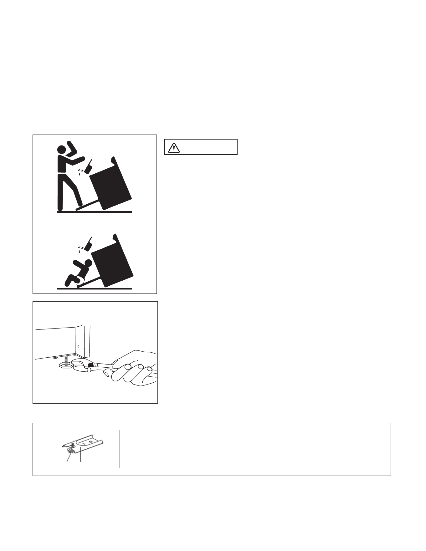
WARNING
A child or adult can tip the range and
be killed. Install the anti-tip device to the structure and/
or the range. Verify the anti-tip device has been properly
installed and engaged. Engage the range to the anti-
tip device by ensuring the anti-tip device is re-engaged
when the range is moved. Re-engage the anti-tip device
if the range is moved. Do not operate the range without
the anti-tip device in place and engaged. See installation
instructions for details. Failure to do so can result in death
or serious burns to children or adults.
Making sure the anti-tip bracket is installed:
• Slide range forward.
• Look for the anti-tip bracket securely attached to floor.
• Slide range back so rear range foot is under anti-tip bracket.
X2
Range Foot Anti-tip Bracket
16
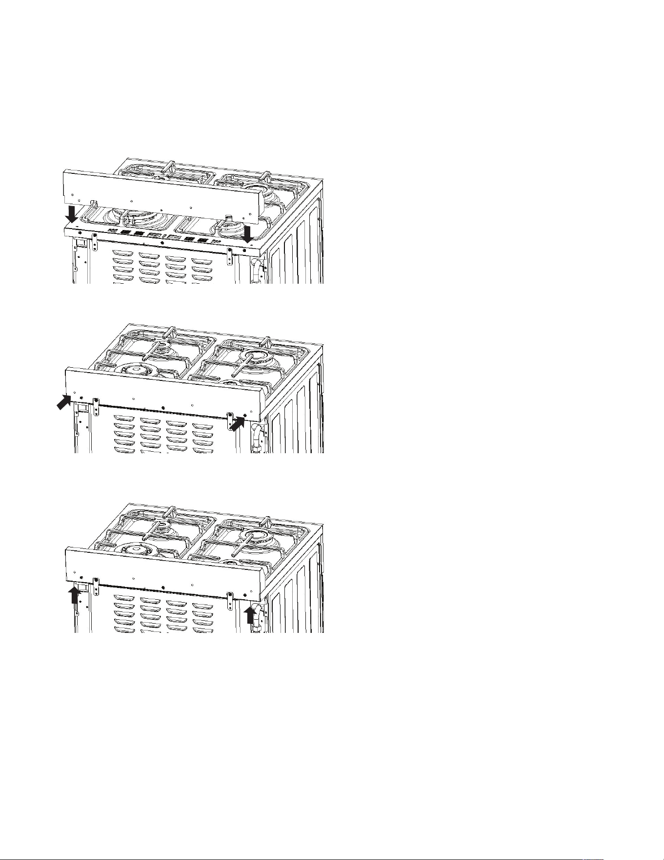
HOW TO INSTALL THE BACKSPLASH
1. Align the backsplash to the rear part of
the cooktop as shown in the diagram.
3. Secure the backsplash from the bottom
using the Phillips head screws provided as
shown in the diagram.
2. Secure the backsplash to the cooktop
from the back using the 2 Phillips head
screws provided as shown in the diagram.

17
NOTICE TO MASSACHUSETTS APPLIANCE DEALERS:
Be sure this document is included in all gas range appliances sold to consumers in the State
of Massachusetts.
NOTICE: Massachusetts law requires the following:
• Appliances must be installed by a licensed plumber or gas fitter.
• Appliances must be connected with a three (3) foot (36” maximum length) flexible gas
connector and
• A “T” handle type manual gas valve in the gas supply line to the appliance.
Have the dealer where you purchase your new range install it or have him recommend a
qualified installer. Installation must conform with local codes. In the absence of local codes,
the installation must conform with the National Fuel Gas Code, ANSI Z223.1-Latest Edition in
the U.S.A. or the CAN/CGA B149.1 or .2 Installation Codes in Canada.
The range should be connected to the supply line with ½” black iron pipe or a certified flexible
type range connector. To prevent gas leaks, put an approved sealing compound, which is
resistant to liquefied petroleum gases, on all threaded connections.
Important: Do not apply pressure directly to the range manifold pipe when tightening supply
connections. The manifold pipe should be held securely at the pressure regulator to prevent
twisting. Hold the pressure regulator with a wrench during the tightening of the connection,
or the manifold pipe may be twisted and split, and cause a dangerous leak.
The installation of ranges designed for manufactured (mobile) home installation must
conform with the Manufactured Construction and Safety, Title 24 CFR, Part 3280, [formerly
the Federal standard for Mobile Home Construction and Safety, Title 24, HUD (Part 280)] in
the U.S.A. or C.S.A. Standard CAN/CGA Z240.4.2 in Canada or, when such standards are not
applicable with local codes.
The installation of ranges designed for recreational vehicle installation must conform to
state or other codes and in the absence of such codes with the standard for recreational
vehicles ANSI A119.2.2–1982 in the U.S.A. or CAN/CGA Z240.4.2 in Canada. The installation of
appliances designed for recreational park trailers must conform to recreational park trailers,
ANSI A119.5.
Note: Check all piping connections in the unit for leaks. Never use an open flame to check for
gas leaks. Use a soap solution with a recommended ratio of 75% water and 25% dish washing
soap. It’s possible for connections made at the factory to leak, due to vibration encountered in
transportation. Make certain you have checked them all, and repair any connections that leak.
GAS CONNECTIONS
18
The appliance and its individual shut-o valve must be disconnected from the gas supply
piping system during any pressure testing of that system at test pressures in excess of
1
/
2
psig.
The appliance must be isolated from the gas supply piping system by closing its individual
manual shut-o valve during any pressure testing of the gas supply
piping system at test pressures equal to or less than
1
/
2
psig.
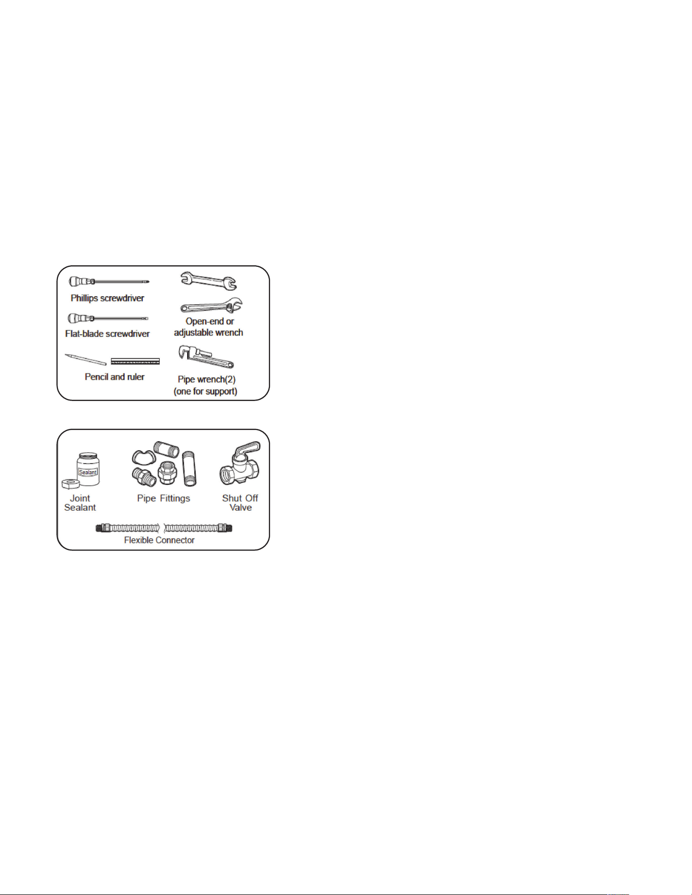
• Gas line shut-o valve
• To reduce the possibility of gas leaks, apply Teflon
tape or a thread compound approved for use with LP
or Natural gases to all threaded connections.
• Use a flexible appliance connector to connect
your gas supply to the appliance. A 3 foot length
is recommended for ease of installation but other
lengths are acceptable. Never use an old connector
when installing a new range.
• Check for leaks using a leak detector or soapy water
with a recommended ratio of 75% water, 25% dish
washing soap.
Installation
It is the responsibility of the installer to make
certain that the range is properly adjusted at the
time of installation. Situations caused by improper
adjustments or improper installation are not covered
under the warranty. Any expenses incurred due to
such situations will not be paid by the manufacturer of
the appliance.
Connecting gas to range
This range is designed to operate at a pressure of 5” of
water column on natural gas (NG) or 10” of water column on propane gas (LPG).
Make sure you are supplying your range with the type of gas for which it is designed. This
range comes equipped from the factory equipped for use with NG (natural gas). This range
is convertible for use on propane (LPG) also (propane orifices included in the packaging).
GAS CONNECTIONS (continued)
TOOLS YOU WILL NEED
MATERIALS YOU MAY NEED

19
When using this on LPG gas, conversion must be made by a qualified LPG installer before
attempting to operate the range on that gas.
For correct operation, the pressure of natural gas supplied to the regulator should be between
4” and 5” of water column. For LP gas, the pressure supplied must be between 10” and 12” of
water column.
When checking for correct operation of the regulator, the inlet pressure must be at least 1”
more than the operating -manifold- pressure as given above. The pressure regulator located at
the back of the range manifold must remain in the supply line regardless of whether natural or
LP gas is being used.
Regulator is only good for psi (14” w.c.) so test pressure must not exceed
1
/
2
” psi.
Shut o the main gas supply valve before removing the old range and leave it o until the new
hook-up has been completed.
Because hard piping restricts movement of the range, the use of a CSA/ETL certified
flexible metal appliance connector is recommended unless local codes require a hardpiped
connection. Never reuse an old connector when installing a new range. If the hard piping
method is used, you must carefully align the pipe; the range cannot be moved after the
connection is made.
To prevent gas leaks, use pipe joint compound resistant to LP or NG gases (depending on set
up) on all male -external- pipe threads.
1. In an easily accessible location, install a service manual gas shut o valve. Be sure everyone
operating the range knows where and how to shut o the gas supply to the range.
2. When all connections have been made, be sure all range controls are in the o position and
turn on the main gas supply valve. Check for gas leaks by using a soap and water solution.
If a gas leak is present, shut o gas immediately, tighten all connections, and retest for
leaks.
3. Any opening in the wall behind the appliance and in the floor under the appliance must be
sealed.
After installation:
1. Check ignition of cooktop burners.
2. Check ignition of oven burner.
3. Check ignition of broiler burner.
4. Check for gas leaks at all gas connections (using a gas detector, never a flame)
GAS CONNECTIONS (continued)
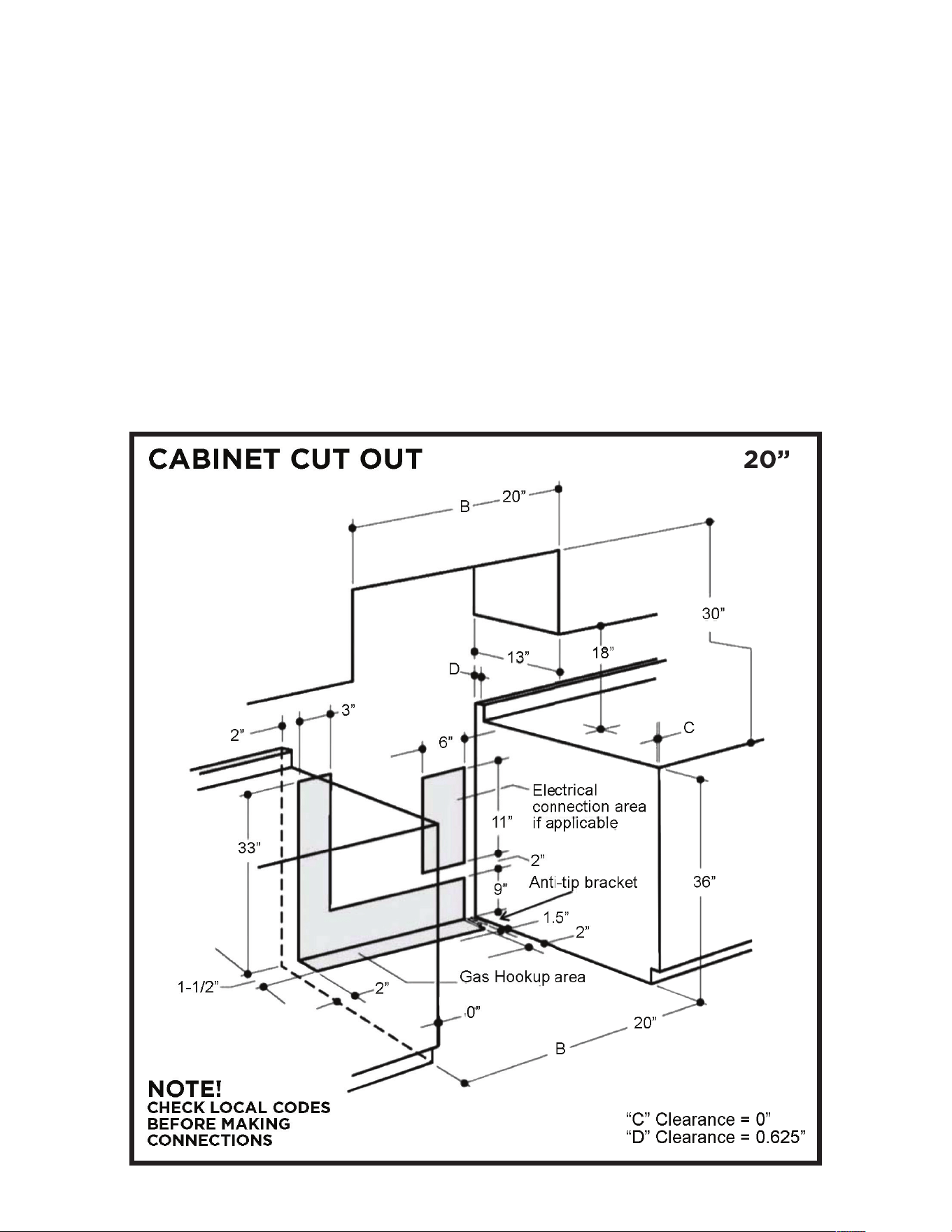
20
All units must be installed in accordance to minimum rear and side wall clearance and
clearances extended vertically above cooking top which are stated on the serial plate located
at the back of the range.
ANY OPENINGS IN THE WALL BEHIND THE UNIT AND IN THE FLOOR UNDER THE UNIT
MUST BE SEALED.
Note: Due to potential hazards it is recommended that storage cabinets NOT be installed
above the cooking surface.
IN THE EVENT OVERHEAD CABINETS ARE INSTALLED, THE MAXIMUM DEPTH OF
CABINETS INSTALLED ABOVE COOKING TOPS SHOULD BE 13”.
WALL CLEARANCES & ANTI-TIP LOCATION
20”
20”
21
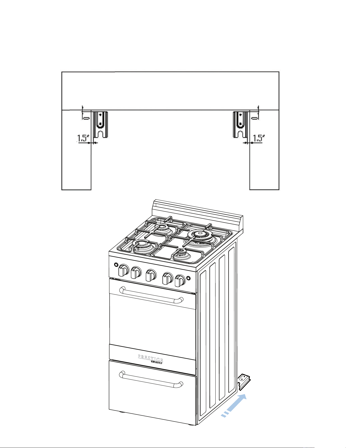
WALL CLEARANCES & ANTI-TIP LOCATION (continued)
Anti-Tip Bracket Location
22
TO CONVERT APPLICATION AND/OR ADJUST FROM NG TO LPG
The range is set for use with Natural Gas (NG). The factory setting is indicated on the serial
plate. When set for Natural Gas operation, the pressure regulator will regulate the gas to
4” water column pressure. When set for Liquid Propane Gas (LPG) operation, the pressure
regulator will regulate the pressure to 10” water column.
NATURAL GAS TO LIQUID PROPANE GAS CONVERSION
The conversion kit must be installed by qualified service agency.
WARNING: Please ensure before beginning converting the appliance that the gas supply is
shut o and the electrical connection is disconnected. Failure to do can result in injury or
property damage.
GAS RANGE CONVERSION
“This conversion kit shall be installed by a qualified service agency in accordance with the
manufacturer’s instructions and all applicable codes and requirements of the authority having
jurisdiction. If the information in these instructions is not followed exactly, a fire, explosion or
production of carbon monoxide may result in property damage, personal injury or loss of life.
The qualified service agency is responsible for the proper installation of this kit. The installation
is not proper and complete until the operation of the converted appliances is checked as
specified in the manufacturer’s instructions supplied with the kit.”
Natural Gas Orifices
BTU 2,700 5,000 11,000 8,500 7,000 8,200
BURNER Auxiliary
Burner
Semi-Rapid
Burner
Triple Burner Rapid Burner Broil Burner Oven Burner
POSITION Front Right Back Left Back Right Front Left
ORIFICE 0.73 1.0 1.5 1.3 1.24 1.3
Liquid Propane Gas Orifices
BTU 2,700 5,000 11,000 8,500 7,000 8,200
BURNER Auxiliary
Burner
Semi-Rapid
Burner
Triple Burner Rapid Burner Broil Burner Oven Burner
POSITION Front Right Back Left Back Right Front Left
ORIFICE 0.53 0.68 1.0 0.9 0.8 0.82
20” MODEL
23
GAS RANGE CONVERSION (continued)
ATTENTION: YOUR PRODUCT IS PRE-INSTALLED WITH NATURAL GAS INJECTORS AND
REGULATOR.
IF YOU ARE USING LP GAS, PLEASE REFER TO THE INSTALLATION INSTRUCTIONS INCLUDED
WITH THE CONVERSION KIT.
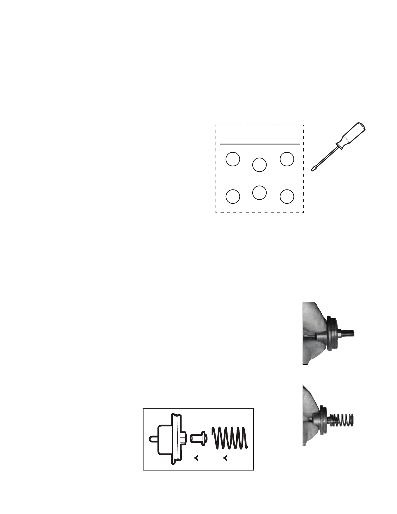
CONVERTIBLE PRESSURE REGULATOR
The range is shipped to operate on NG. LPG
orifi ces for adjusting the minimum fl ame are
shipped with the unit in a separate envelope with
the manual. The inlet pressure of the gas supply
shall be in accordance with the nominal inlet
pressure of the regulator used on the range or ½
psig maximum. The range should be tested by
pressurizing the regulator with an inlet pressure
at least 1” water column above the manufacturer’s
specifi ed manifold pressure shown on the serial
plate.
ORIFICES SCREWDRIVER
RL
OVEN
NOZZLE (LPG)
0.68
FL
0.9
RR
1.0
FR
0.53
0.82
BROILER
2”
2”
0.8
UGP 20V PC1 S/S
UGP 20V PC1 W
UGP 20V PC1 B
CONVERTIBLE PRESSURE REGULATOR
The range is shipped to operate on NG. LPG orifi ces and a special screwdriver for adjusting
the minimum fl ame are shipped with the unit in a separate envelope with the manual. The
inlet pressure of the gas supply shall be in accordance with the nominal inlet pressure of the
regulator used on the range or 1/2 psig maximum. The range should be tested by pressurizing
the regulator with an inlet pressure at least 1 inch water column above the manufacturer’s
specifi ed manifold pressure shown on the serial plate.
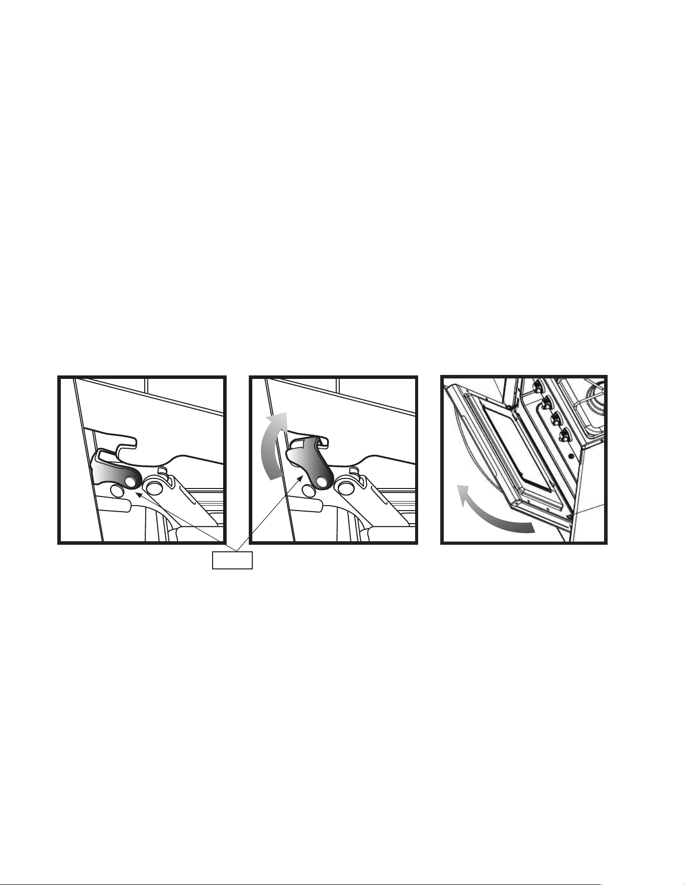
1. CAUTION: Before proceeding with the conversion, shut o the
gas supply to the appliance prior to disconnecting the electrical
power
2. Locate convertible regulator at the back of the range, left
side facing appliance. Remove cap and pop out the pin that’s
attached
3. On the side you will see the pin position for use with LPG
4. Unscrew pin and fl ip it to the LPG position - short end
outwards, spring on outside.
NG
LPG
24
GAS RANGE CONVERSION (continued)
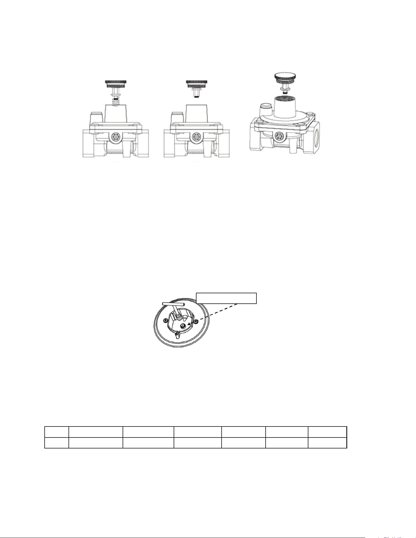
5. Replace the cap back on the regulator
6. Remove the grates, burners and burner caps from the range to
access the orifices.
7. Use a 7 mm wrench to remove the orifices. Each orifice can be
accessed easily - the larger burner orifice is located on the burner wall.
BURNER ORIFICE
8. Remove all NG orifices, place in the bag and store in a safe place.
9. Take the LPG orifices provided and install them as shown below.
See below for rating of orifice for each model
Front Right Rear Right Front Left Rear Left Oven Broil
LPG 0.53 mm 1.00 mm 0.9 mm 0.68 mm 0.82 mm 0.8 mm
10. Once all the orifices are installed, replace all burners and burner caps, then fire up the
burners to check the minimum flame height.
LPG NG
BURNER ORIFICE
ORIFICE LOCATION
25
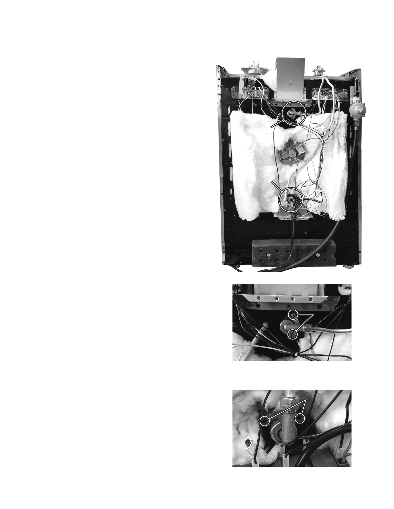
GAS RANGE CONVERSION (continued)
FIG 1. OVEN
FIG 2. BROILER
OVEN
BROILER
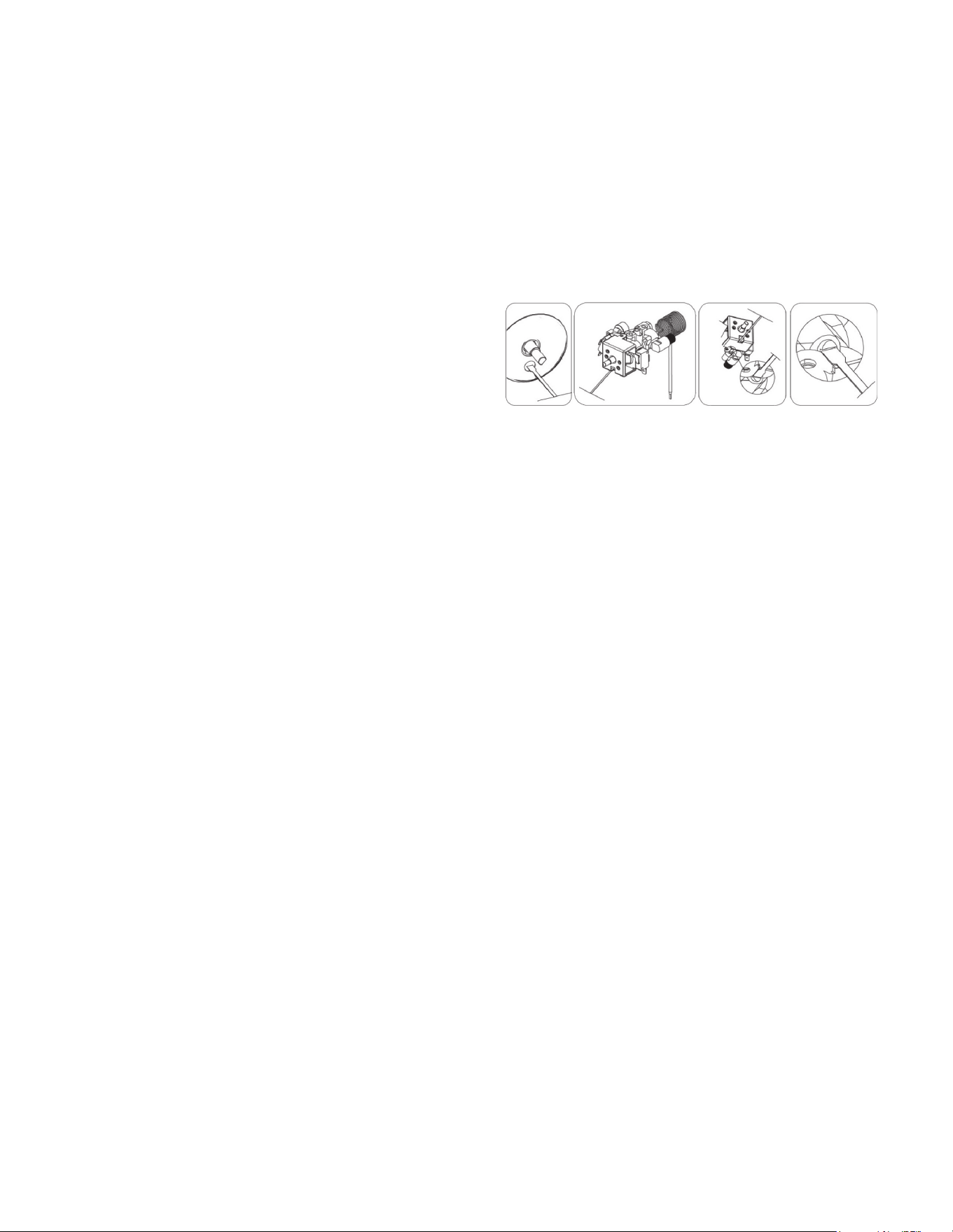
To replace the oven burner orifice
1. Remove the back panel
2. Locate/disconnect oven orifice housing
screws x 2 (Fig 1)
3. Gently bend gas tube to gain access to the
orifice
4. Use a 7 mm socket to remove orifice
and replace with specified orifice for gas
conversion
5. Remount oven orifice housing screws x 2
To replace the broiler burner orifice
1. Locate/disconnect broil orifice housing
screws x 2
2. Gently bend gas tube to gain access to the
orifice (Fig 2)
3. Use a 7 mm socket to remove orifice
and replace with specified orifice for gas
conversion
4. Remount broil orifice housing screws x 2
5. Replace back panel
Note: Check for leaks using a leak detector
or soapy water with recommended ratio of
75% water, 25% dish washing soap. Once you
have completed the conversion, check the
operations of ignition making sure each of
the 4 burners, pilot flame and oven burner
flame are functioning correctly. Please refer
to pages 30 through 35.
SCREWS
SCREWS
26
CHECKING FOR MANIFOLD GAS PRESSURE
To check the manifold gas pressure, remove the burner cap and connect a manometer (water
gauge) or other pressure test device to the burner orifice. Use a rubber hose with inside
diameter of approximately ¼” hold the end of the hose tight over the orifice. Turn the gas
valve on. For a more accurate pressure check, have at least two (2) other top burners burning.
Be sure that the gas supply (inlet) pressure is at least one inch above the specified manifold
pressure. Maximum gas supply pressure must not exceed 14” inch water column, minimum gas
supply pressure must be 1” inch water column above recommended pressure, 12” for propane
gas, and 5” water column for natural gas. When properly adjusted the manifold water column
pressure is 10” for LP/propane gas or 5” for natural gas.
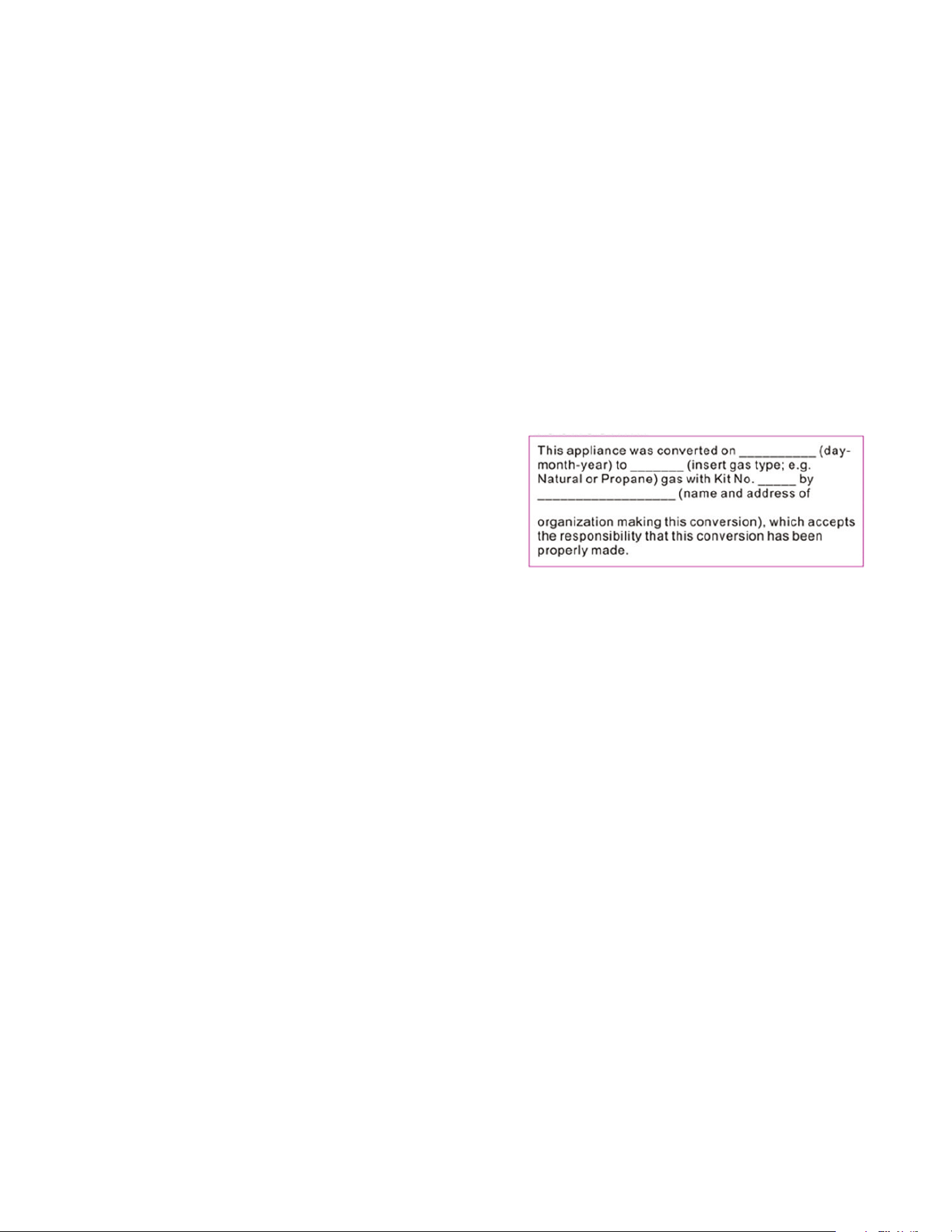
Note: Once the unit has been converted fill out the included sticker and place it on the back
of the range
Once you have completed the conversion, check
the operations of ignition making sure each of the
4 burners, pilot flame and oven burner flame are
functioning correctly. Please refer to pages 30 thru
35 – Operation of Range.
High Altitude Applications above 2,000 feet: At
elevations above 2,000 feet, the range must be derated 4% for each 1,000 feet above sea
level. It is the installer’s responsibility to see that the range’s input rate is adjusted properly.
GAS RANGE CONVERSION (continued)
27
ADJUSTING THE TOP BURNER AND OVEN FLAME
Keep appliance area clear and free from combustible materials, gasoline, and other
fl ammable vapors and liquids. Do not obstruct the fl ow of air that is necessary for
combustion and ventilation.
TOP BURNER VALVES
The top burners have orifi ces that are dedicated to the type of fuel to be used. These orifi ces
are not adjustable. They must be changed completely to convert from one gas to the other. DO
NOT DISCARD THE UNUSED ORIFICES. They should be saved in order to convert the range
back to its original fuel.
When converting the gas valves, the minimum fl ame adjustment screw must be adjusted.
Please see the supplied screwdriver in the conversion kit along with the orifi ces. The proper
fl ame size is approximately ¼” obtained. – see adjustment procedure below.
The properly adjusted maximum fl ame is approximately ¾” high and has three distinct cones;
the kindling point, the dark blue center cone, and the outer mantel.
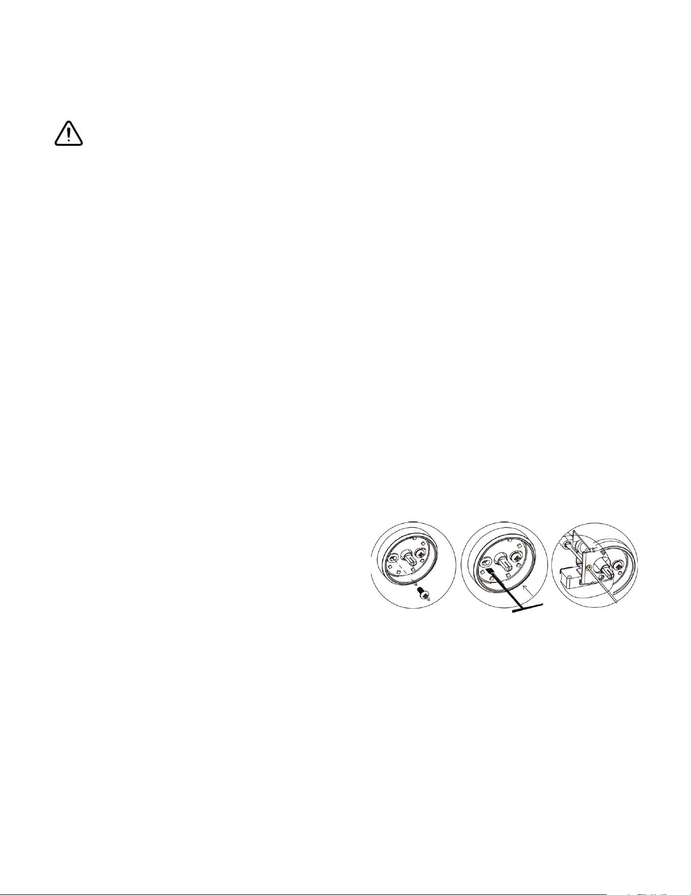
ADJUSTING THE TOP BURNER FLAME
1. Ensure the range has gas supply and power
2. Light the burner
3. Set the top burner valve to the minimum position
4. Remove the knob by pulling straight out
5. Locate the bypass screw behind the left screw (see illustration)
Remove the left screw Insert the fl at head
screwdriver (2.5 mm x 75 mm - provided) into
the screw hole and turn the by pass screw
clockwise to adjust the fl ame
Do not overtighten.
6. Replace the knob
7. Repeat for each of the other burners
28
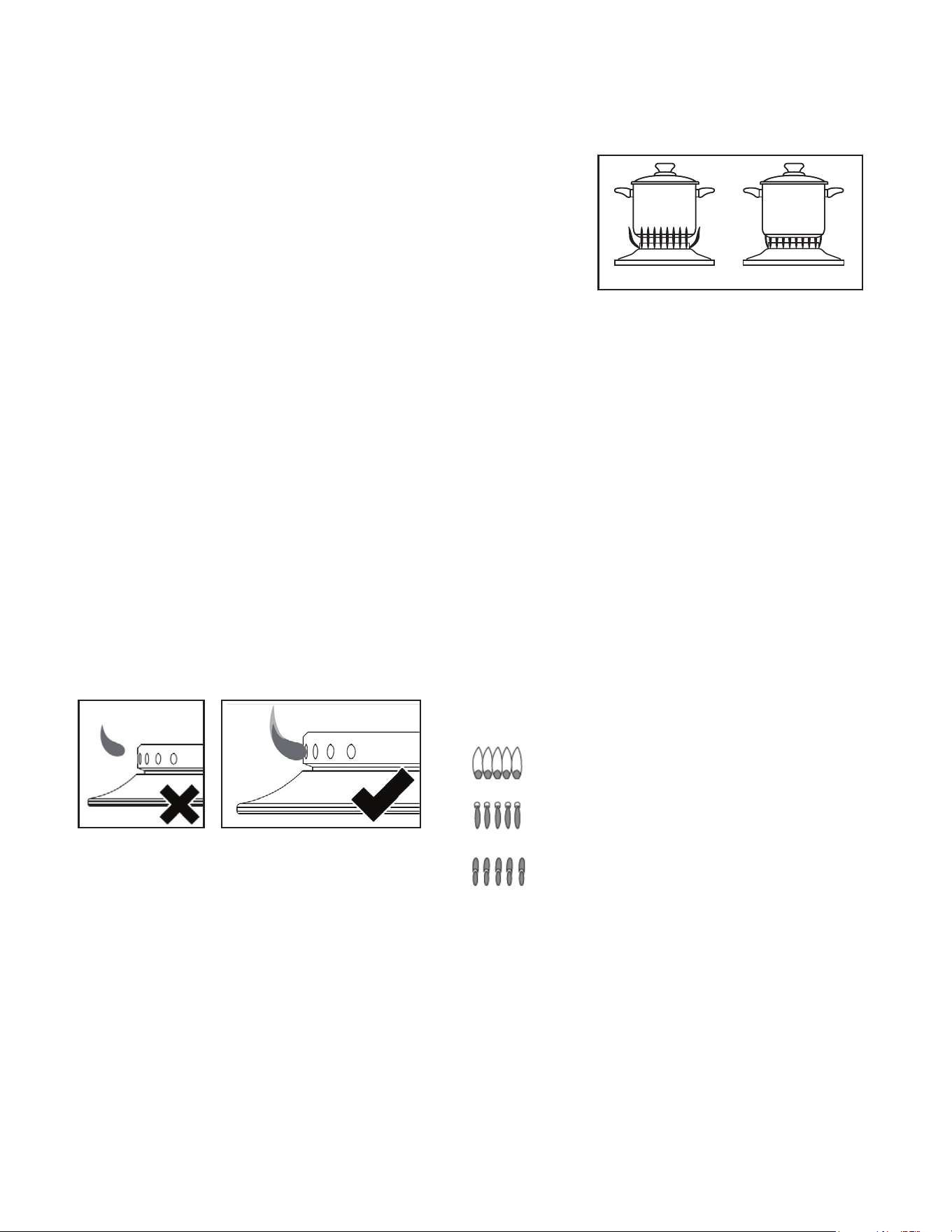
COOKTOP BURNER OPERATION
The top burner flame size should be adjusted so that is does
not extend beyond the edge of the cookware. As a matter
of safety, it’s recommended that you comply with these
instructions.
A high flame on a surface burner is both inecient and unsafe. The flame should always be
adjusted so that it is no larger than the bottom of the pan. Fluctuations in flame size could be
caused by pressure variations, improperly positioned burners, damage or debris.
To light a burner, press the burner knob in and turn counter clockwise to high flame/ignition
position. You will hear the electronic ignition clicking as you continue to hold the knob down
until the flame lights. ALL electrodes will spark at a rate of approximately 2½ pulses (sparks)
per second. Continue to hold the knob depressed until gas ignites at the burner. Adjust the
intensity of top burner heat in the same manner described above.
Note: In the event the electronic ignition system fails, the top burners and oven pilot can be lit
by holding a lighted match near the burner head and turning the appropriate top burner knob
to the “9 o’clock position”.
ADJUSTING THE TOP BURNER AND OVEN FLAME
(continued)
Oven
Pilot
Igniter
Pilot Orifice
Thermocouple
Oven
Pilot
Igniter
Pilot Orifice
Thermocouple
INCORRECT AND GOOD FLAME PATTERNS
If burner flames look like A, call for service.
B or C is normal burner flames, depending on the type of
gas you use.
With LP gas, some yellow tipping on outer cones is normal.
QUALITY OF FLAMES
The combustion quality of burner flames needs to be
confirmed visually.
A. Yellow flames — Call for service
Incorrect: flame
lifting off the
burner
Good flame: Well-defined
blue flame with slight yellow
tipping
Oven
Pilot
Igniter
Pilot Orifice
Thermocouple
Top Burner Height
C. Soft blue flames — It is normal for natural gas
B. Yellow tips on outer cones —
It is normal for LP gas
INCORRECT CORRECT
29
TIP: Before proceeding, take note of the original burner bypass screw placement.
ADJUSTING THE OVEN BURNER FLAME
1) Light the burner by turning the thermostat to the 500°F position,
2) Remove the knob by pulling straight out.
3) Remove the two (2) Phillips head screws that
secure the bezel to the control panel.
4) Carefully lift the bezel away from the control
panel to allow access to the access hole
below the valve stem. (see illustration).
5) Insert the fl at head screwdriver (2.5 mm x 75 mm) into the screw hole and turn the bypass
screw clockwise to adjust the fl ame.
DO NOT OVERTIGHTEN.
6) Mount the knob to the valve stem.
7) Allow the oven to heat up for approximately 10 minutes then rotate the knob to the 300°F
position to operate the thermostat by-pass. Slowly screw the by-pass screw until you obtain
a fl ame of approximately 3 – 4 mm in height.
8) Carefully replace the bezel and knob ensuring not to damage wires.
OVEN VALVE
The oven control has a fl ame safety device built into the body of the thermostat.
Presence of a gas ignition source (pilot) is verifi ed by a fl ame safety probe. This fl ame safety
probe actuates the internal safety device to allow gas into the oven burner when the oven is
turned on. If there is a loss of gas ignition during operation, the fl ame safety device will close
o gas fl ow to the oven burner and pilot.
The oven burner orifi ce is located on a brass injector stud at the rear of the oven under the
oven fl oor. This orifi ce is dedicated to the gas for which the oven is to be used. The orifi ce is
not adjustable. It must be changed completely to convert from one gas to the other. DO NOT
DISCARD THE UNUSED ORIFICE. It should be saved in order to convert the range back to its
original fuel
ADJUSTING THE TOP BURNER AND OVEN FLAME
(continued)
30
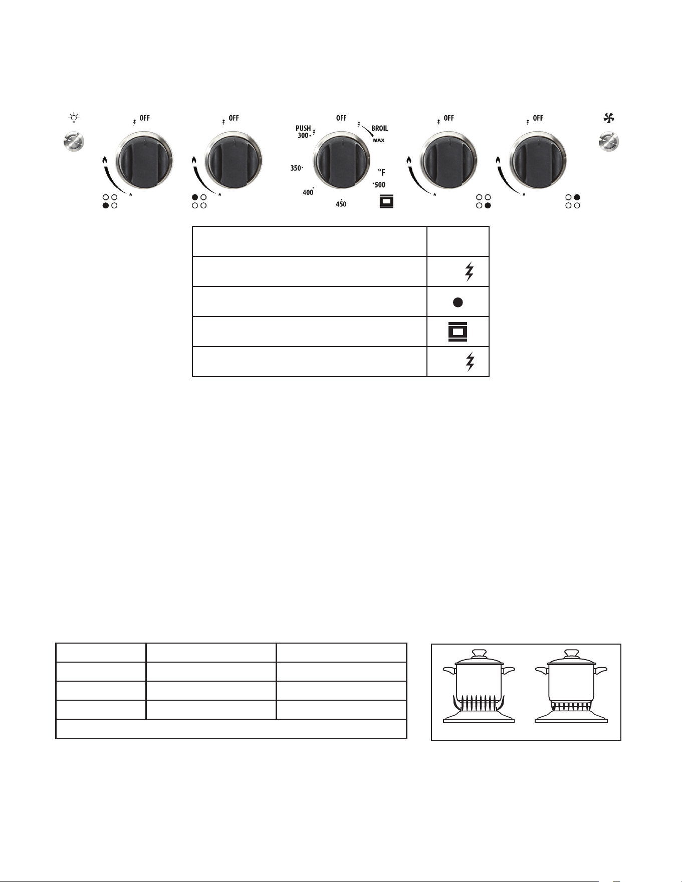
OPERATION OF RANGE
20” MODEL
O
OFF
Push & rotate left to ignite oven
PUSH
Burner position
Oven
Push & rotate right to ignite broiler
BROIL
INCORRECT CORRECT
LIGHTING THE TOP BURNERS
1. To obtain a flame more easily, light the burner before placing a cooking utensil on the
burner grate.
2 Decide which burner you’re igniting first using the screened diagram below the burner
knob. The black dot indicates the position of the burner you’re igniting.
3. To light a burner, press the burner knob in and turn counter clockwise to high flame/
ignition position. You will hear the electronic ignition clicking as you continue to hold the
knob down until the flame lights.
4. After lighting the flame, turn the control knob to adjust the flame size as required.
CHOICE OF BURNER
DIAMETERS OF PANS WHICH MAY BE USED ON THE TOP BURNERS
BURNER MINIMUM MAXIMUM
Auxiliary
4.72” (12 cm) 5.5”(14 cm)
Semi-rapid
6.29” (16 cm) 9.44” (24 cm)
Rapid
9.44” (24 cm) 10.23” (26 cm)
Do not use pans with concave or convex bases
31
OPERATION OF RANGE (continued)
HOW TO USE THE GAS OVEN
General features
The gas oven is provided with two burners:
The Oven burner, mounted on the lower part of the oven
The Broil burner, mounted on the upper part of the oven
Using the oven for the first time
It is advised to follow these instructions:
- Insert shelves and broiler grid and tray
- Turn the oven on to the maximum temperature position (500˚F) to eliminate possible traces
of grease from the oven burner. The same operation should be followed for the Broil burner
(knob on position BROIL).
- Unplug the power cord, let the oven cool down, then clean the interior of the oven with cloth
soaked in water and detergent (neutral) then dry carefully.
OVEN BURNER
Performs the normal “oven cooking” function.
- The gas flow to the burner is regulated by a thermostat which maintains the desired oven
temperature.
- The control of the temperature is determined by a thermostatic probe positioned inside the
oven.
- The probe must be always kept in its housing, in a clean condition, as an incorrect position or
a dirty probe may cause improper control of the temperature.
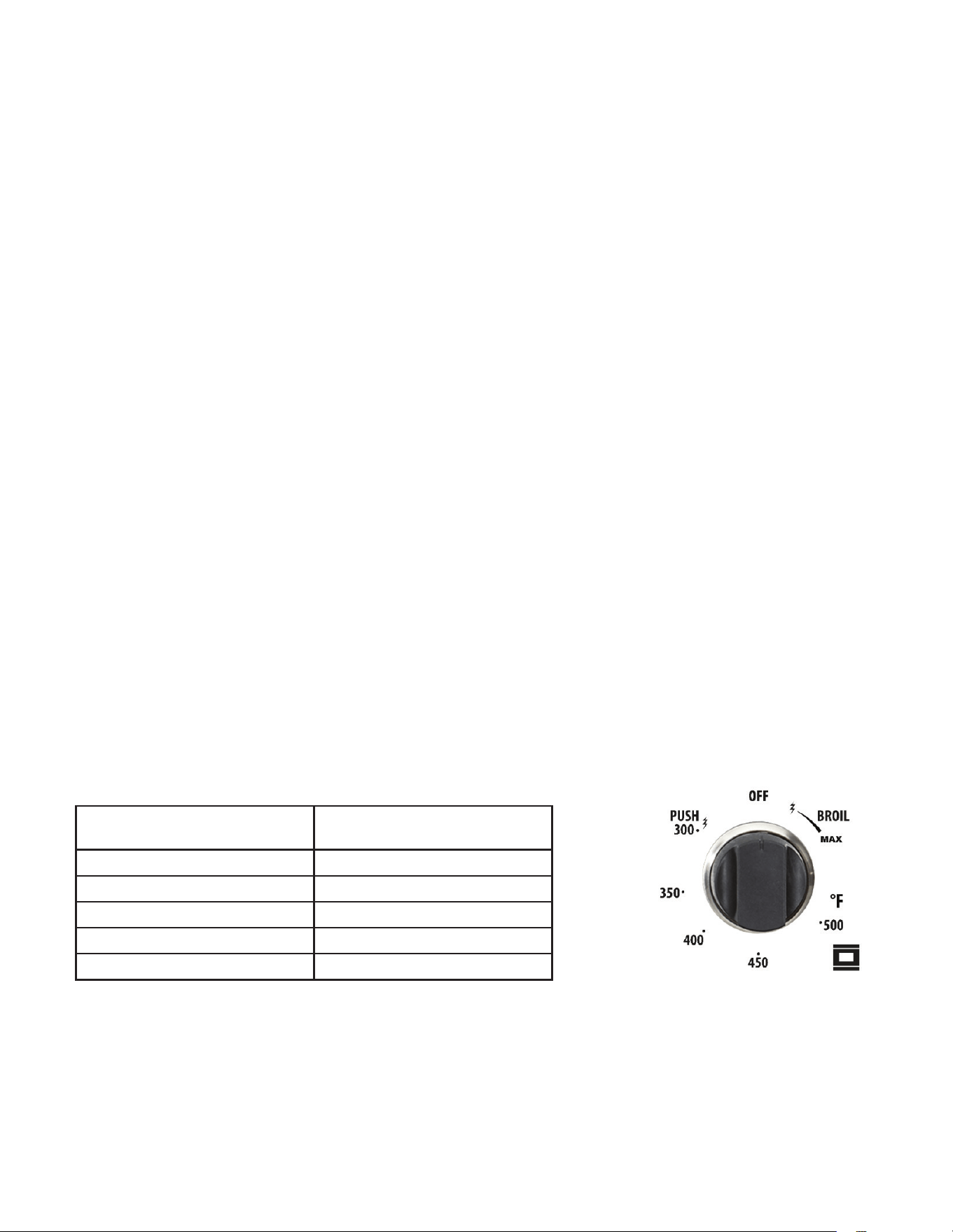
GAS OVEN SETTING
Number printed on the
knob (temperature in ˚F)
Corresponding
temperature in ˚C
300 149
350 177
400 204
450 232
500 260
OVEN THERMOSTAT
- The numbers printed on the control panel indicate the increasing oven temperature value
(°F).
- To regulate the temperature, set the chosen number onto the control knob indicator.
- The position BROIL serves only to turn on the broil burner.
Note: When the range will not be used for long periods of time, set the gas knobs to their OFF
32
OPERATION OF RANGE (continued)
positions and also close the gas shut-o valve placed on the main gas supply line.
VERY IMPORTANT: The oven/broil shall be used always with the door closed.
VERY IMPORTANT: Never obstruct the oven vent slots on the backsplash.
- Important: Use always suitable protective gloves when inserting/removing the broiling pan,
shelves, pans on other cooking utensils from the oven.
- Attention: the range becomes very hot during operation
- Attention: the oven door becomes very hot during operation; be sure to use the handle to
open/close.
- Keep children away from the stove/oven when it is in use.
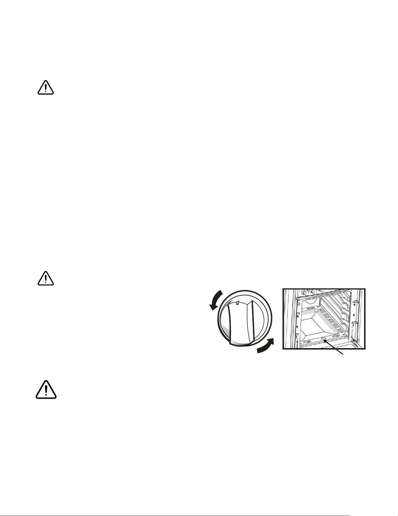
IGNITION OF THE OVEN BURNER
The thermostat allows the automatic control of the temperature.
The gas delivery to the oven burner is controlled by a two way thermostatic tap (oven and
broil burners) with flame-failure device.
To light the oven burner operate as follows:
1. Open the oven door to its full extent.
WARNING: Risk of explosion! The oven door must be open during this operation.
2. Lightly press and turn the thermostat knob
counter-clockwise to max position or 500°F.
3. Press the knob inward and hold to activate
the electronic ignition. Note that you will hear
a “clicking” noise. Hold the knob pressed
inward until the oven burner is lit. Once the
oven burner is lit, release the knob.
In case of power outage, you can manually light the burner by pressing the knob inward and
immediately approach a lighted match to the opening “A” (see the diagram above).
Never continue this operation for more than 15 seconds. If the burner has still not
ignited, wait for about 1 minute prior to repeating the ignition.
4. When using the range for the first time or after long period of non-usage, keep pressing
the knob inward for approximately 10 – 15 seconds after the burner has lit to ensure the gas
valve has been accurately primed.
5. Close the oven door slowly and adjust the burner accordingly to the desired temperature.
If the flame extinguishes for any reason, the safety valve will automatically shut o the gas
supply to the burner.
To re-light the burner, first turn the oven control knob to the OFF position, wait for at least 1
minute and then repeat the lighting procedure.
Attention: the oven door becomes very hot during operation. Keep children away.
A
33
MOISTURE
IMPORTANT
If sparking does not occur when the oven thermostat knob is turned on during the initial
attempt to use, or after several days of non-use, it COULD BE the result of moisture build-up
in the ceramic sleeve of the oven electrode. This may happen in areas with high humidity, or
if food having high water content is cooked. This moisture can be driven out of the ignitor by
lighting the pilot and operating the oven for a few minutes.
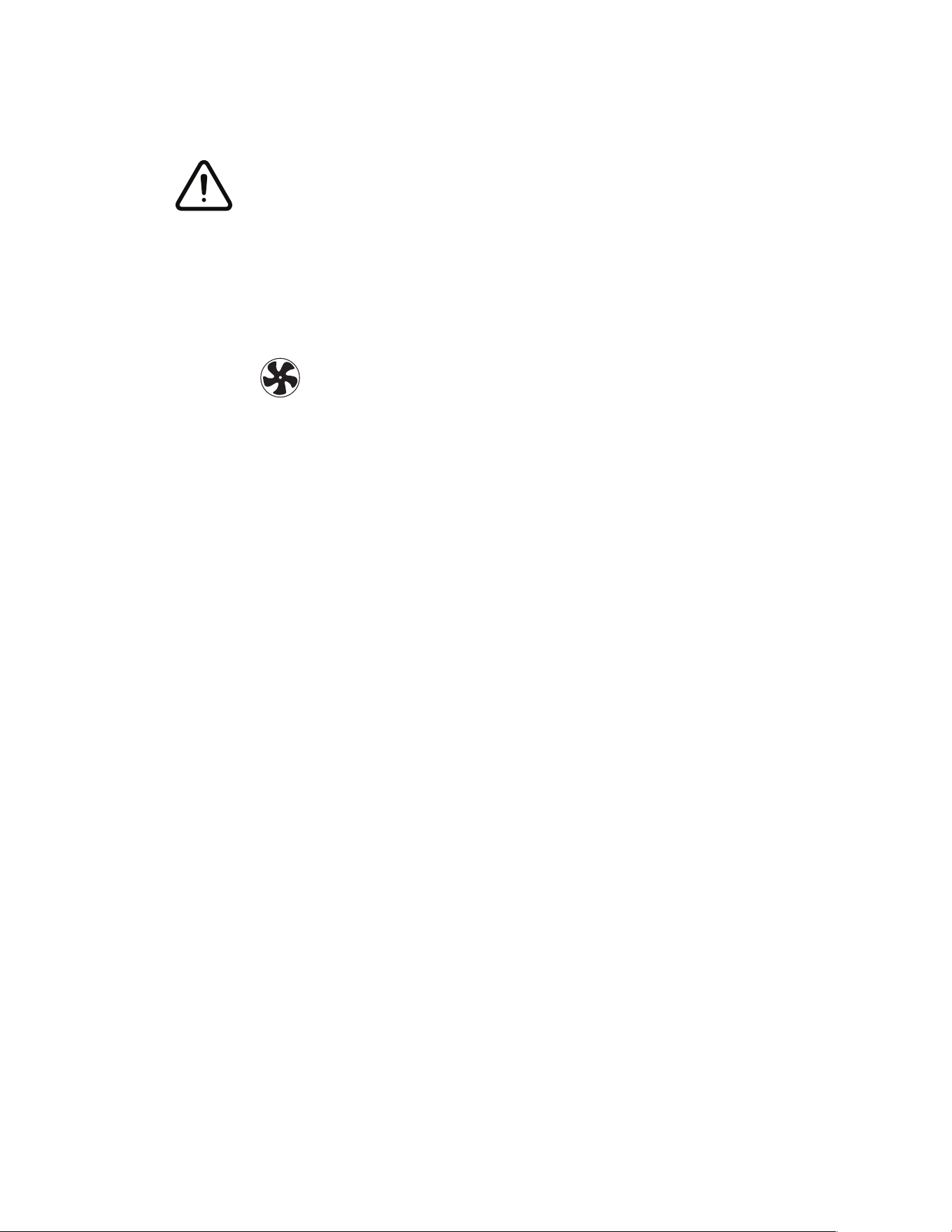
CONVECTION MODE
Heat is transferred from the bake burners in the bottom of the oven cavity to the oven cavity
itself. The convection fan in the rear of the oven then circulates the hot air, providing even
heat distribution throughout the oven. Convection cooking generally provides a more even
temperature with faster baking times than the standard oven baking setting. This mode is
controlled by a switch on the right hand side of the control panel. Simply flick the switch in to
activate it.
• Position the oven’s bottom cover and the oven shelf/shelves before using the oven. Use more
than one oven shelf for larger baking loads. Remove any unused shelves and baking utensils
from the oven.
• Preheat the oven to the temperature stated in the recipe before baking. Depending on the
temperature needed and the size of the oven, preheating will take 15 - 20 minutes.
• Arrange pans and food items evenly on the shelves. Make sure pans do not touch each other
or the sides of the oven. When baking a single item, always center the item on the oven shelf,
preferably in the center of the oven. If baking on multiple shelves, make sure to stagger items
on the shelves so that one is never directly above another.
NOTES ABOUT CONVECTION COOKING
Convection cooking generally provides a more even temperature with faster baking times
than the standard oven baking setting. When baking in Convection Mode, either reduce the
temperature stated in the recipe and leave the baking time unchanged, or reduce the baking
time by several minutes and leave the temperature unchanged. For foods with a baking time of
over an hour, reducing both the temperature and the time slightly may give the best results.
• Dark metal baking pans or those with a dull finish absorb heat faster than shiny pans, and are
excellent for pies, breads and anything that needs browning or a crisper crust.
• Shiny finish or light coloured pans may work best for foods that require lighter, more delicate
browning or a crisper crust as they reflect some heat, creating a less intense baking surface.
• Avoid opening the oven door frequently during baking as this aects temperature and
eciency.
OPERATION OF RANGE (continued)
34
OPERATION OF RANGE (continued)
CONVECTION ROASTING
When convection roasting, it is important that you use a broiler pan for best convection
roasting results. A broil/roast pan (with a rack) elevates the roast to allow the hot air to
circulate around the meat, sealing in juices for a moist and tender roast with a richly browned
exterior (similar to a rotisserie eect.) The pan is also used to catch any drippings from the
roast, keeping the oven clean and reducing the chance of smoking or flare-ups. The convection
fan circulates heated air evenly over and around the food, sealing in juices for a moist and
tender roast with a richly browned exterior.
CONVECTION DEFROST
With the temperature control o, a motorized fan in the rear of the oven circulates air. The fan
accelerates natural defrosting of the food without heat. To avoid bacteria growth, food-borne
illness and food waste, do not allow defrosted food to remain in the oven for more than 2 hours
without being cooked.
CONVECTION DEHYDRATE
With the temperature control at 175˚F, warm air is radiated from the bake burners in the
bottom of the oven cavity and is circulated by a motorized fan in the rear of the oven. Over
time, this constant circulating heat evaporates moisture from food, which inhibits bacteria
growth and halts enzyme activity
NEVER LEAVE THE CONTROL KNOBS IN ANY POSITION OTHER THAN “OFF” IF THE
IGNITORS OR BURNERS AREN’T WORKING PROPERLY.
IGNITION OF THE BROIL BURNER
To light the broil burner operate as follow:
1. Open the oven door to its full extent.
WARNING: Risk of explosion! The oven door
must be open during this operation.
2. Lightly press and turn the thermostat knob
clockwise to the broil position.
3. Press the knob inward and hold to activate the
electronic ignition. Note that you will hear a
“clicking” noise. Hold the knob pressed inward
until the oven burner is lit. Once the oven burner
is lit, release the knob. In case of power outage,
you can manually light the burner by pressing the
knob inward and immediately approach a lighted
match to the area noted in the diagram above.
Never continue this operation for more than 15 seconds. If the burner has still not ignited,
wait for about 1 minute prior to repeating the ignition.
35
OPERATION OF RANGE (continued)
4. When using the range for the fi rst time or after long period of non-usage, keep pressing
the knob inward for approximately 10 – 15 seconds after the burner has lit to ensure the gas
valve has been accurately primed.
5. Slowly close the oven door. If the fl ame extinguishes for any reason, the safety valve will
automatically shut o the gas supply to the burner.
To re-light the burner, fi rst turn the oven control knob to the position, wait for at least 1
minute and then repeat the lighting procedure.
Always broil with oven door closed. Attention: the oven door becomes very hot during
operation. Keep children away.
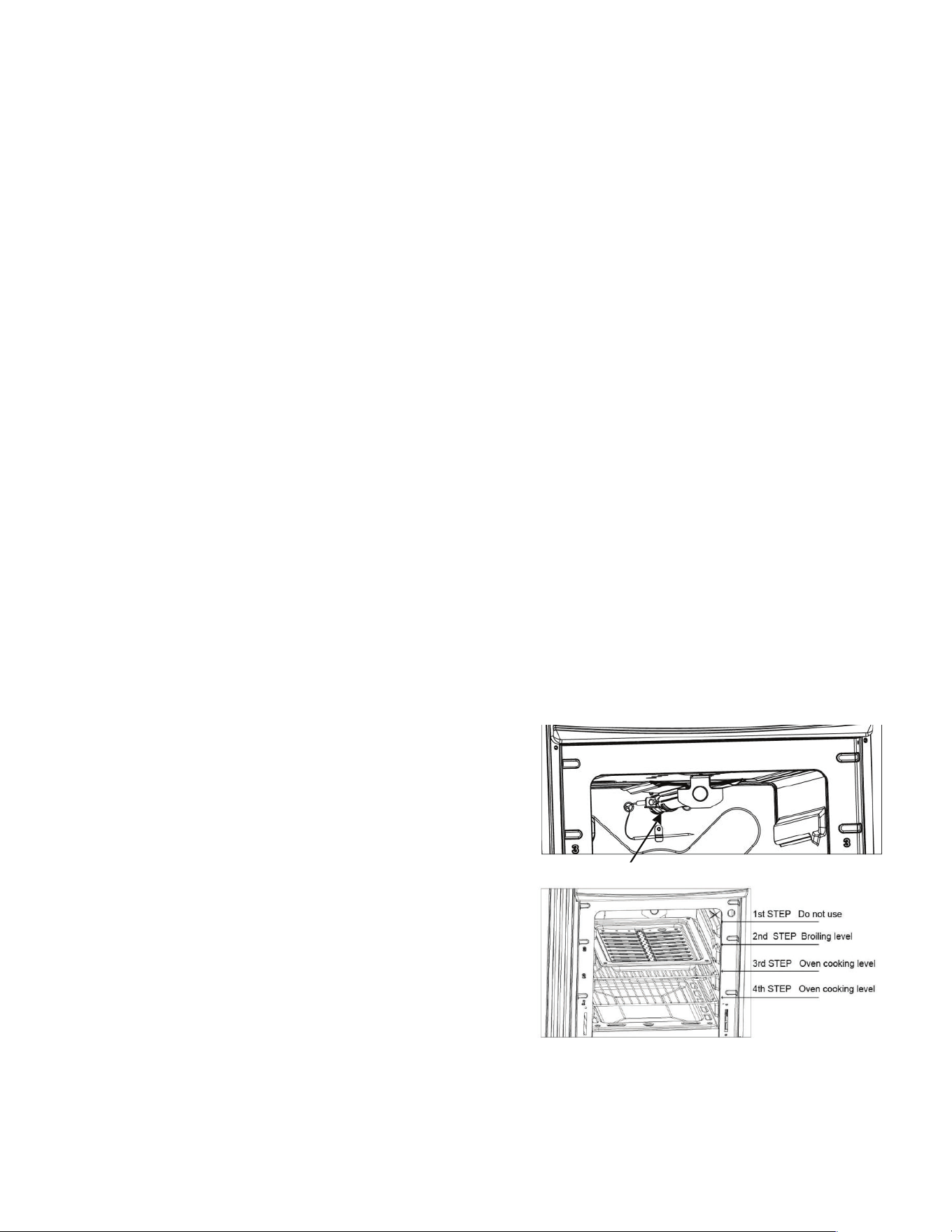
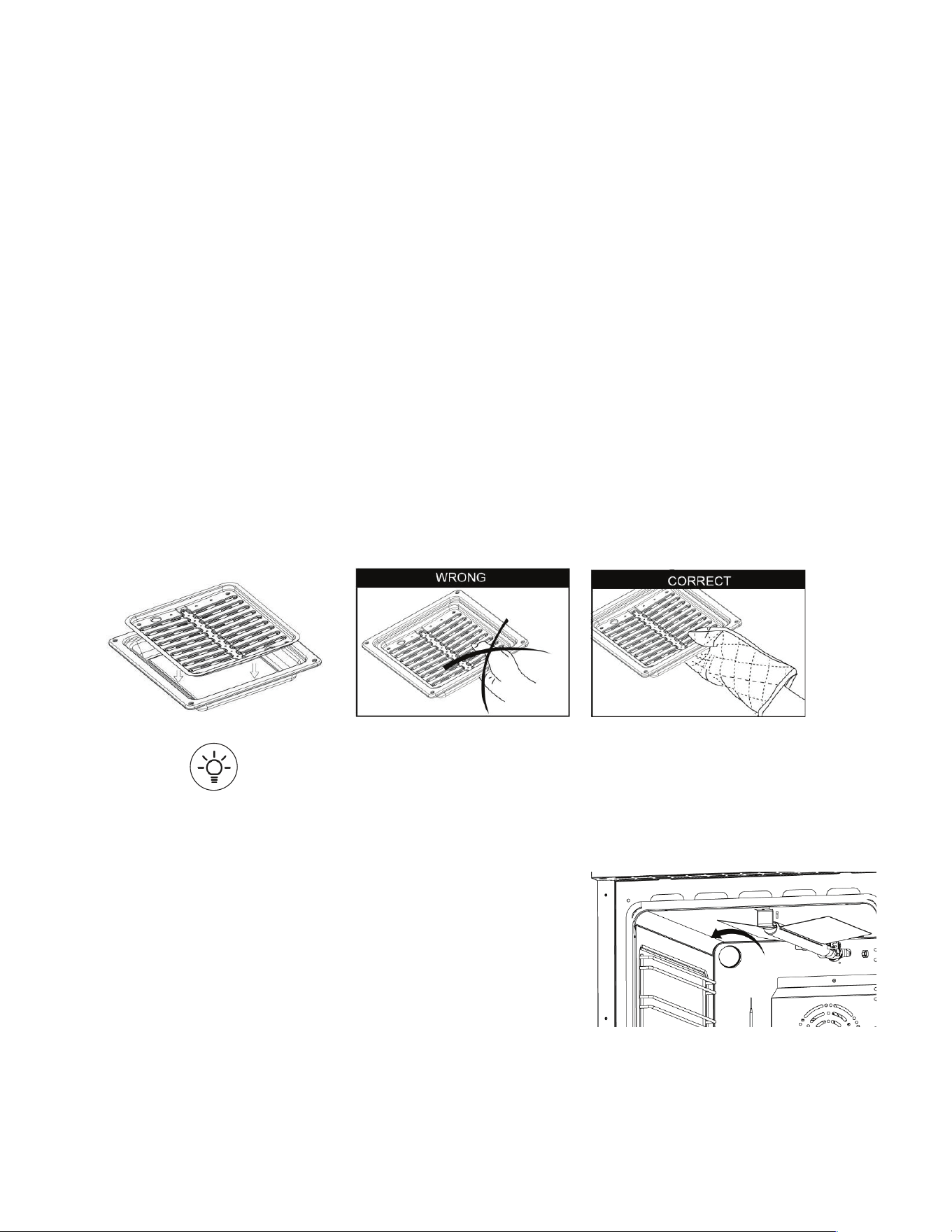
BROILING
Very important: the broil burner must always be used with the oven door closed.
Position the oven rack on the second level from the top
1. Turn on the broil burner, as explained in the preceding paragraphs and let the broil burner
preheat for about 5 minutes with the door closed.
2. Place the food to be cooked below the broiler.
OVEN LIGHT
The range is equipped with a light that illuminates the oven to enable visually controlling the
food that is cooking. This light is controlled by a switch on the left hand side of the control
panel. Simply fl ick the switch to activate the light.
CHANGING OVEN LIGHT BULB
Remove light bulb cover and unscrew light bulb counter
clockwise. Replace with an E14 120V 25W 300°C bulb.
36
GENERAL RECOMMENDATION
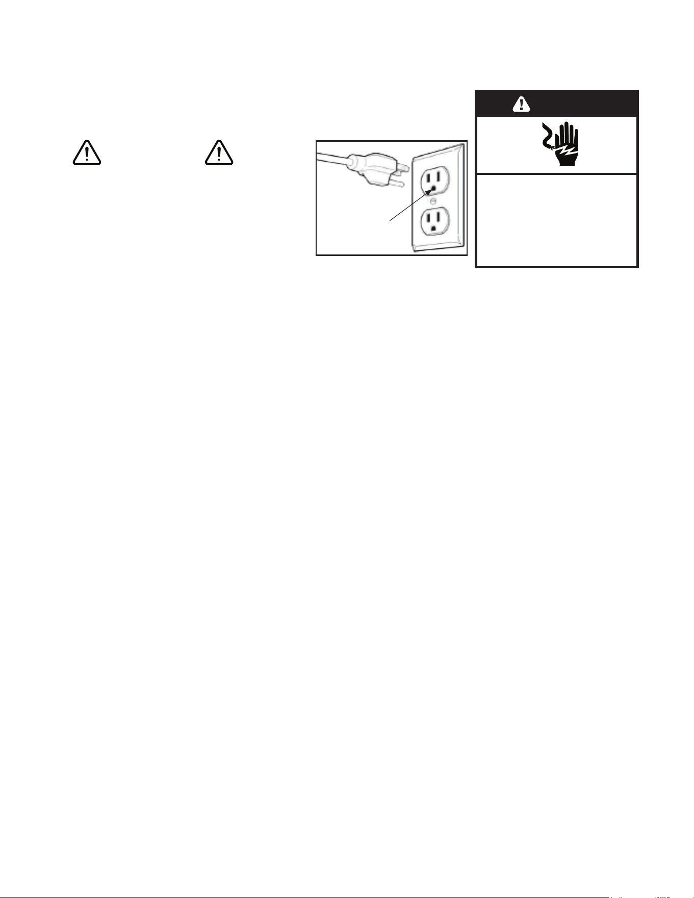
WARNING
Electrical Shock Hazard
• Plug into a grounded 3-prong outlet.
Insure proper ground exists before
using the range.
• Do not remove ground prong.
• Do not use an adapter or extension cord.
• Failure to follow these instructions can result in death, fi re, or electrical shock.
Important: Before any operation of cleaning and maintenance disconnect the appliance from
the electrical supply.
It is advisable to clean when the appliance is cold and especially for cleaning the enameled
parts.
Avoid leaving alkaline or acidic substances (lemon juice, vinegar, etc.) on the surfaces. Avoid
using cleaning products with a chlorine or acidic base.
The oven must always be cleaned after every use, using suitable products and keeping in mind
that its operation for 30 minutes on the highest temperature eliminates most grime reducing it
to ashes.
Always keep cleaning materials and chemicals in a safe place and away from children. Know
what you are using. Make sure all parts of the range are COOL before cleaning. Be sure to
replace the parts correctly.
Knobs
Pull forward on the knobs to remove them. Wash in a water solution with a mild detergent mix.
Do not use an abrasive cleaner or any abrasive action. Abrasive action will scratch the knobs.
If the knobs become loose on the valve stem, spread the valve stem slightly with a small
screwdriver.
Using Commercial Oven Cleaners
Commercial oven cleaners may be used on porcelain lined ovens; however, many cleaners are
very strong, and it’s essential to follow instructions carefully. Be sure to wear rubber gloves to
protect your hands.
After using such cleaners, thoroughly rinse the oven with a solution of 1 tablespoon vinegar to 1
cup of water. Oven cleaners can coat or damage the thermostat sensing device (the long tube
in the oven) so that it will not respond to temperature accurately. If you use an oven cleaner, do
not let it contact the sensing bulb, or any chrome, aluminum, or plastic part of the range.
Do not apply or allow the cleaner to come in contact with any parts or surfaces other than
the oven interior.
Electrical Shock Hazard
Plug into a grounded 3-prong outlet.
Do not remove ground prong.
Do not use an adapter.
Failure to follow these instructions can
result in death, fi re, or electrical shock.
WARNING
CLEANING THE RANGE
Insure proper ground
exist before use

37
Grates, Main Tops, Surface Burners
The grates are made of porcelain coated steel. These materials can be cleaned at the sink with
detergent or soap-filled scouring pads. Do not be alarmed when the grate loses its shiny finish.
The heat from the burners will cause the grates to lose their shiny finish.
Clean the burner with soap and water, rinse thoroughly and dry completely before
reassembling. Burner heads can be dried in the oven at about 350 degrees Fahrenheit or in
the dishwasher on the dry cycle. After adjustment or cleaning, replace all parts to their original
position.
Stainless Steel Elements
The stainless steel finish top can be cleaned with detergent and warm water.
Stainless steel parts must be rinsed with water and dried with a soft and clean cloth or with a
chamois leather.
For dicult grime, use a commercially available, non-abrasive product for cleaning stainless
steel surfaces, or a little hot vinegar.
Note: Regular use could cause discoloring around the burners, because of the high flame
temperature.
Products of combustion from the top pilots as well as certain atmospheric conditions can
create an oxidation reaction on the underside of the top. This will appear as rust or in the form
of a reddish brown deposit. This will NOT AFFECT THE LIFE OF THE TOP in comparison to the
general life expectancy of the range itself.
It is very important that the burner be dry before replacing it in the range. A wet burner will not
allow the gas to ignite properly. This could result in a build-up of gas which could result in an
explosion or fire.
CLEANING THE RANGE (continued)

38
ALUMINUM FOIL IN OVEN
WARNING
NEVER cover any slots, holes or passages in the oven bottom or cover an entire rack with
materials such as aluminum foil. Doing so blocks air flow through the oven and may cause
carbon monoxide poisoning. Aluminum foil linings may also trap heat, causing a fire hazard.
Aluminium foil when used improperly is a cause of many range fires. Make certain that vents or
air openings aren’t covered by the foil. If the vents located along the sides of the oven bottom
are blocked, poor cooking will result.
Never cover a rack completely. A piece of foil slightly larger than the cookware can be placed
on the rack beneath the cookware.
Remove and discard aluminum foil after each use. This will help prevent grease and spilled food
from accumulating and becoming a fire hazard.
CLEANERS AND CLEANING MATERIALS
Do not use harsh cleaners or degreasers on or around functional parts (valves, controls, etc., or
aluminum tubing). This will damage or drastically reduce the life of the part.
Use only a mild solution of soap and water on backguards, aluminum control panels and
painted surfaces. Never use harsh abrasives or cleaning powders that may scratch or mar the
surface. Make sure the cleaners and cleaning materials are suitable for use on the area to be
cleaned. Always keep cleaning materials in a safe place. Never use a sharp metal scraper to
clean glass, porcelain, or painted surfaces.
REPAIR PARTS
When repair parts are needed, contact the dealer from whom the range was purchased. In case
your range was purchased from a source other than an appliance dealer, you may prefer to
contact the manufacturer at the address shown in this manual.
MOISTURE
During the initial heat-up of your range, the heat mixing with the cooler air in the oven cavity
may produce fogging of the door glass or a collection of water on the door. To prevent this,
open the oven door for the first few seconds of initial oven heat-up. This will allow the moist air
within the oven to escape, without the forming of visible moisture on the range. The amount of
moisture will depend upon the humidity of the air and water content of the food being cooked.
Fogging and even dripping water will usually occur in geographic locations of high humidity.
CARE AND MAINTENANCE
39
BURNERS AND CAST-IRON GRIDS
• These parts can be removed and cleaned with appropriate products.
• After cleaning, the burners and their flame distributors must be well dried and correctly
replaced.
• It is very important to check that the burner flame distributor and the cap has been correctly
positioned - failure to do so can cause serious problems.
• In appliances with electric ignition keep the electrode clean so that the sparks always strike.
Note: To avoid damage to the electric ignition do not use it when the burners are not in
place.
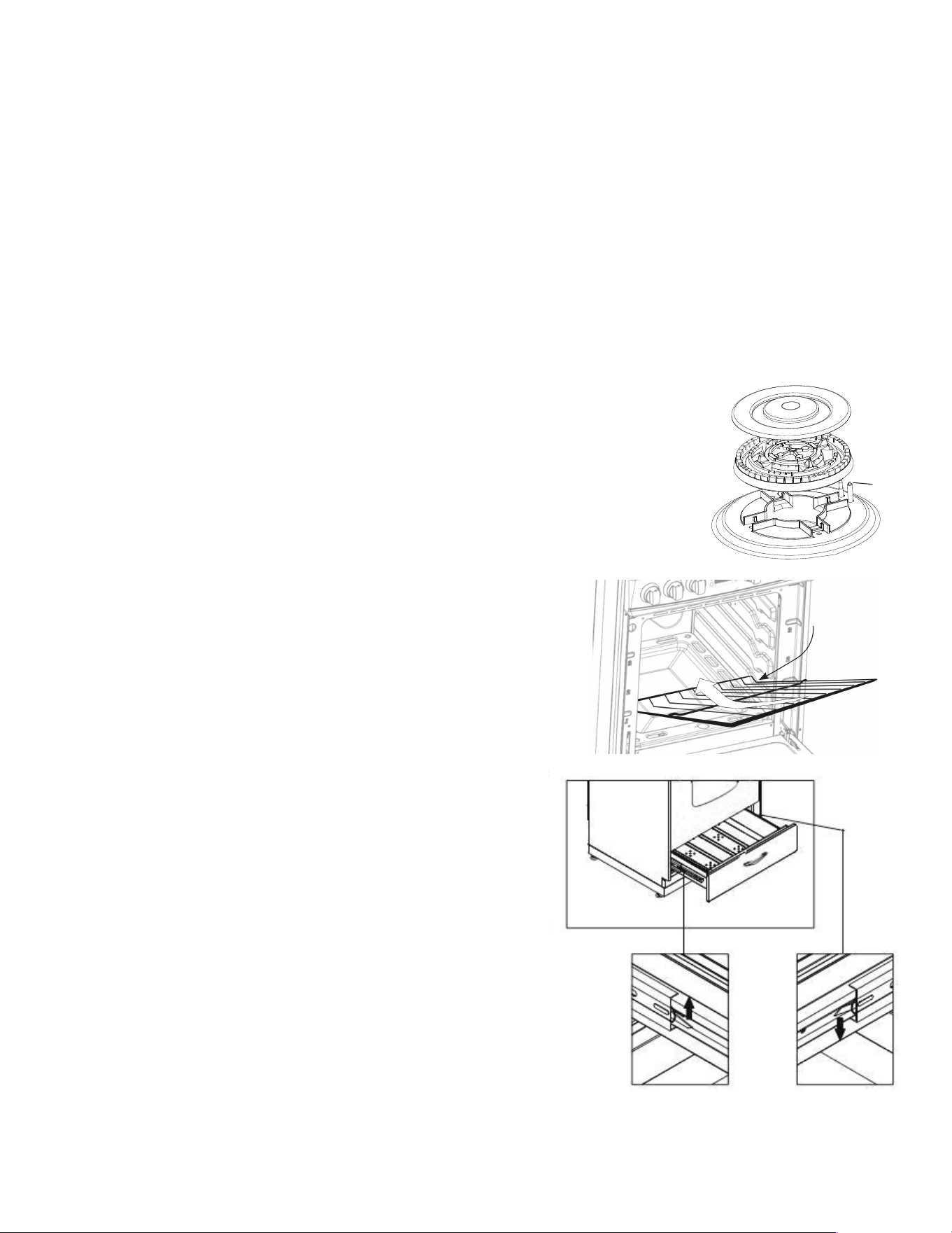
CORRECT REPLACEMENT OF THE BURNERS
It is very important to check that the burner flame spreader “F” and
the cap “C” have been correctly positioned. Failure to do so can cause
serious problems. In appliances with electric ignition, check that the
electrode “S” is always clean to ensure trouble-free sparking.
The ignition plug must be cleaned very carefully.
OVEN RACK INSTALLATION AND REMOVAL
• The oven racks are provided with a safety catch to prevent
accidental removal.
• They must be inserted as shown.
• To pull them out remove the rack in the reverse order.
REMOVABLE STORAGE DRAWER
1. Lift the left small hook upward, at the same time,
push the right small hook downward. (see the picture)
2. Pull the drawer out.
3. To replace the drawer, align the drawer with the rails
and push inward.
DO NOT STORE FLAMMABLE MATERIAL IN THE OVEN
OR IN THE BOTTOM DRAWER.
CARE AND MAINTENANCE (continued)
C
F
S
SAFETY CATCH
40
CARE AND MAINTENANCE (continued)
REMOVING THE OVEN DOOR FOR CLEANING
To facilitate oven cleaning, it is possible to remove the door. Please follow the instructions
carefully:
The oven door can easily be removed as follows:
• Open the door to fully.
• Lift the left and right hooks on the hinge figure (A,B).
• Hold the door as shown in figure (C) on a 45 degree angle.
• Gently close the door until the hooks touch the door, then lift at a 45 degree angle
• Set the door on a soft flat surface.
• To replace the door, repeat the above steps in reverse order.
(C)(B)(A)
HOOK
41
CARE AND MAINTENANCE (continued)
REPLACING THE OVEN LIGHT
• Let the oven cavity and broil burner cool down.
• Switch o the electric supply.
• Remove the protective cover.
• Unscrew and replace the bulb with a new one suitable for high temperature (200°~
500°F) having the same specifications: 120V 60Hz, 15W, E14.
• Replace the protective cover.
NOTE: Oven bulb replacement is not covered by your guarantee.
LEVELING THE RANGE
The range must be level to obtain proper operating. The four screws type leveling legs
located on the corners at the bottom of range should be adjusted by turning them
clockwise to make the range higher or counter-clockwise to lower the range until the
range is level. Use a level on surface units to check the leveling of the range.
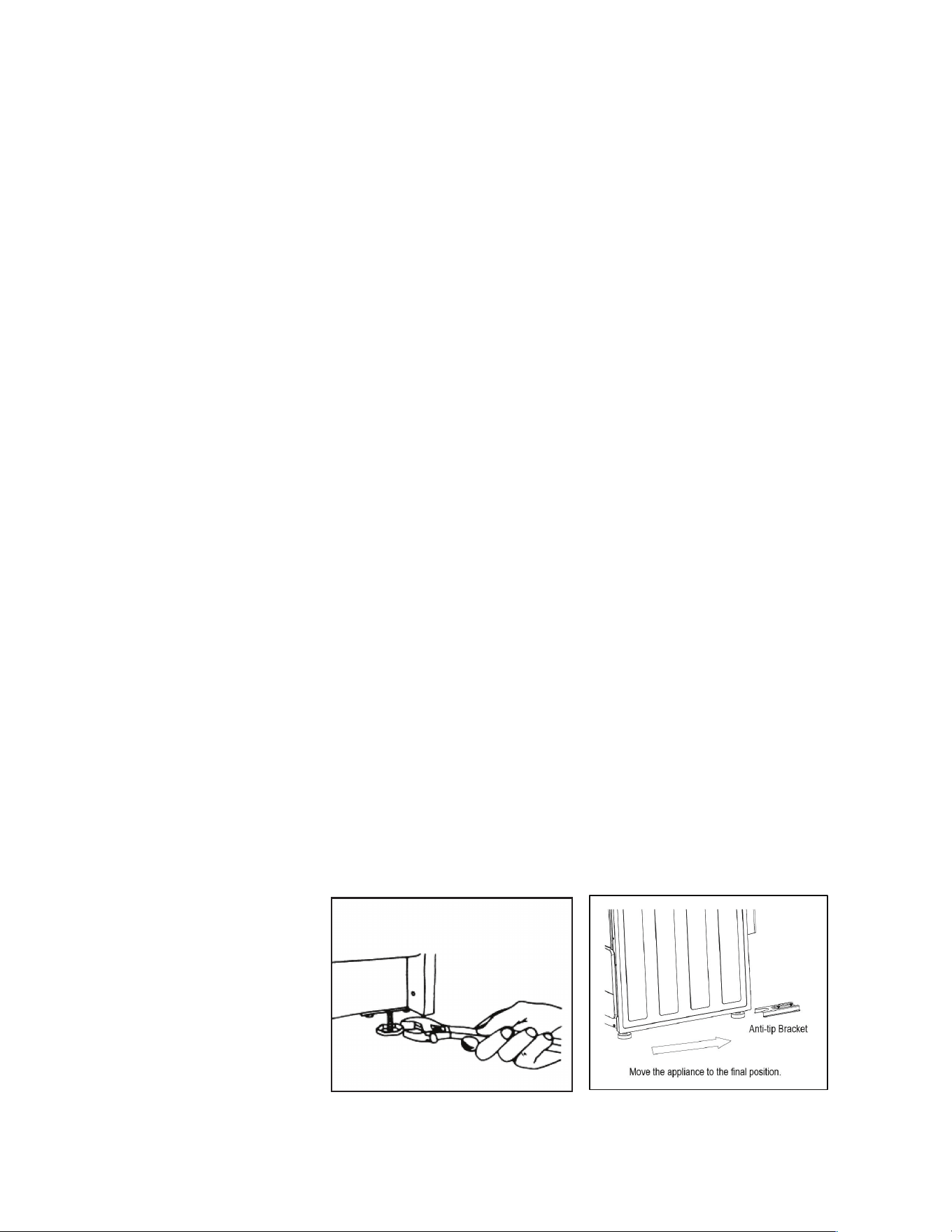
ANTI-TIP BRACKET INSTALLATION
To reduce the risk of tipping the range by abnormal usage or improper door loading,
the range must be secured by properly installing the anti-tip device packed with the
appliance.
• Place the anti-tip bracket on the floor as shown figure. Anti-tip bracket can be installed
on the right and left side.
• Make the locations of 2 (x2) holes of ant-tip bracket on the floor.
• Use a drill bit
• Secure bracket to floor using screws supplied.
• Slide appliance into position.
NOTE: If range is relocated, the bracket must be removed and installed in new location.
Ø
NOTE: If range is relocated, the bracket must be removed and installed in new location.
42
TROUBLESHOOTING
PROBLEM POSSIBLE CAUSE POSSIBLE FIX
Surface burners
do not light.
Surface control has not been
completely turned to the ON
position.
Push in and turn control to the ON
position until burner ignites, then turn
control to desired flame setting.
Burner ports are clogged. Use a small gauge wire or needle to
open ports.
Burners not positioned properly. Verify that the burners are positioned
properly on the orifice hoods and the
burners are sitting flat on the burner
support with tabs engaged in slots.
Range not set for appropriate
gas input.
See range conversion section of
installation manual.
Burners won’t light due to power
failure.
Light burners manually.
Range power cord is
disconnected from the outlet.
Be sure power cord is plugged into
grounded outlet.
Flame burns
halfway round.
Burner ports are clogged. Use a small gauge wire or needle to
open ports.
Moisture is present after cleaning. Lightly fan the flame and allow
burner to operate until flame is full.
OR dry burners thoroughly following
instructions in range “Cleaning”
section.
Range is not set for appropriate
gas input.
See range conversion section of
installation manual.
Flame is orange. Dust particles in main line. Allow burner to operate for a few
minutes until flame turns blue.
Range is not set for appropriate
gas input.
See range conversion section of
installation manual.
Oven light does
not work.
Burned out or loose bulb Tighten or replace oven light bulb.
Oven or broiler
does not heat.
Range is not set for appropriate
gas input.
See range conversion section of
installation manual
Temperature control not set
properly.
Make sure temperature control is set at
desired temperature.
Burners will not light due to
power failure.
Light burners manually.
House fuse has blown or circuit
breaker has tripped.
Check/reset circuit breaker and/or
replace fuse. Do not increase fuse
capacity. If the problem is a circuit
overload, have it corrected by a
qualified electrician.
Range cord is disconnected from
outlet.
Be sure the power cord is plugged into
a grounded outlet.
43
PROBLEM POSSIBLE CAUSE POSSIBLE FIX
Oven
temperature is
inaccurate.
Oven capillary bulb not
positioned properly.
Verify that capillary bulb is snapped in
clips straight and not touching sides or
coated with oven cleaner or food.
Temperature control not set
properly.
Make sure the temperature control
knob is set at the desired temperature.
Improper use of foil. Keep foil clear of holes in oven bottom
and o of oven sides.
Vent blocked. Keep vent on backguard clear.
Range not set for appropriate
gas input.
See range conversion section of
installation manual.
Smoke/odor
on initial oven
operation.
This is normal.
Range is not
level
Poor installation. Place oven rack in centre of oven.
Place a level on the rack. Adjust
leveling legs.
Weak or unstable floor. Be sure floor is level and can
adequately support range. Contact
carpenter to correct sagging or
sloping floor.
Kitchen cabinet misalignment
may make range appear to be
unlevel.
Be sure cabinets are square and have
sucient room for range clearance.
Contact cabinet maker to correct
problem.
Oven smokes
excessively.
Meat too close to broiler burner. Reposition the broiler pan to provide
more clearance between the meat and
the broiler burner.
Meat not prepared properly. Remove excess fat from meat.
TROUBLESHOOTING (continued)
44
20寸电路图贴纸
铜板不干胶贴纸
订单号 客户地区业务
王浙科
1.铜板不干胶纸
2.字体图案印刷清晰
GC0178
加拿大
GC0178-231501
(用量:1PCS)贴与后背板
254
102
尺寸:102*254
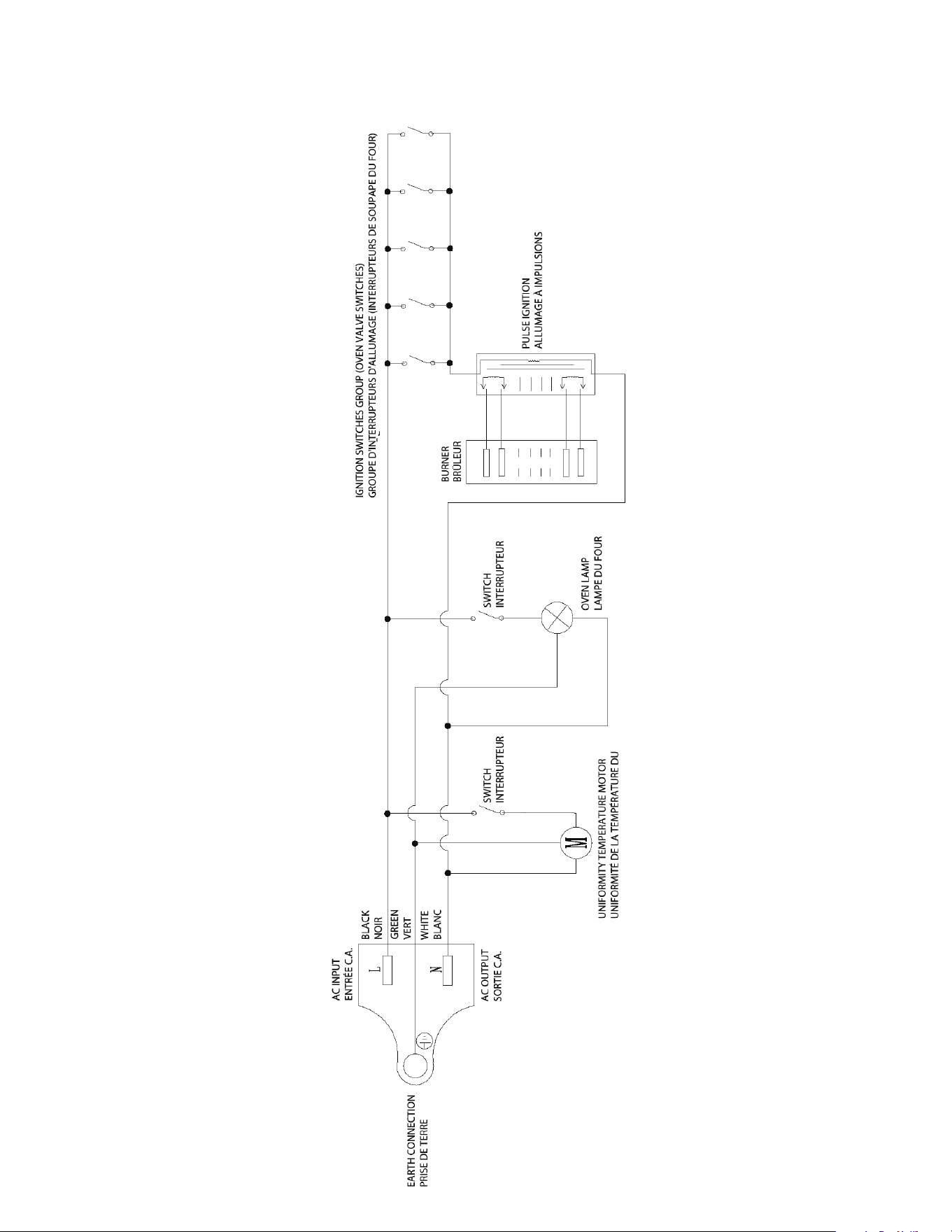
Wiring Diagram
Schéma de Câblage
Model/Modèle
UGP 20V PC1 S/S
UGP 20V PC1 W
UGP 20V PC1 B
WIRING DIAGRAM
45
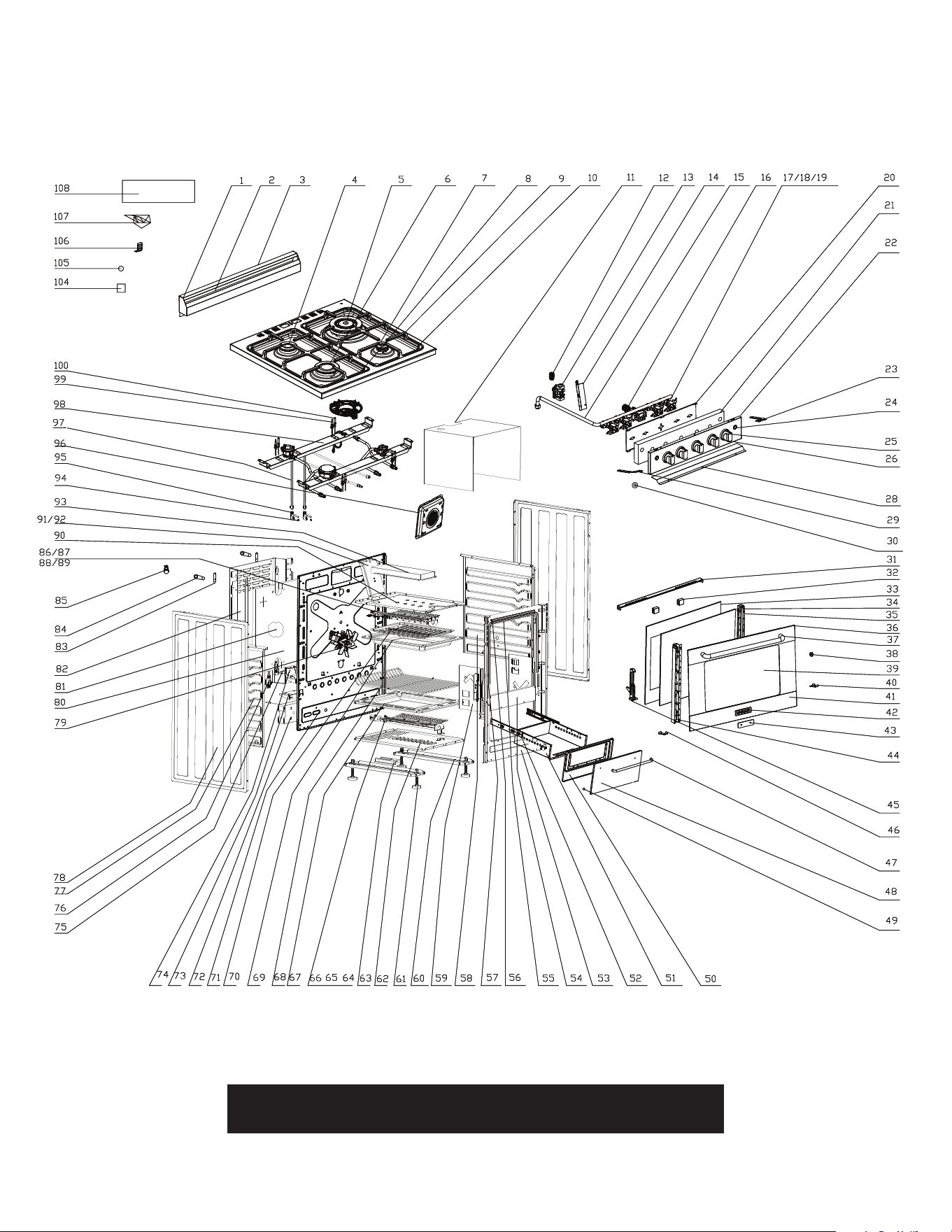
PARTS DIAGRAM AND LIST
Please visit our website www.uniqueappliances.com to view a PDF
version of the schematics which will allow you to zoom in & out
46
PARTS DIAGRAM AND LIST
Item # Description Part #
1 Backsplash UGP-G20H08-011600
2 Backsplash inner plate UGP-G20H08-011700
3 Backsplash cover UGP-G20H08-011500
4 75 burner UGP-G20A02-040100
5 130 burner UGP-G20A02-040300
6 100 burner UGP-G20A02-040200
7 55 burner UGP-G20A02-040000
8 Grates (left) UGP-G20H08-021300
9 Grates (right) UGP-G24C05-021600
10 Cooktop UGP-G20H08-020100
11 Cavity heat insulation plate UGP-C20B01-074500
12 Regulator adaptor UGP-G24G02-034200
13 NG5 "LPG10" Regulator UGP-G20C01-034002
14 Regulator support UGP-G24G02-034500
15 Gas pipe UGP-G20H08-030700
16 Thermostat UGP-G20C02-030619
17 Valve-0.50 UGP-G20D02-030535
18 Valve-0.81 UGP-G20D02-030533
19 Valve-0.95 UGP-G20D02-030534
20 Control panel inside panel UGP-G20H08-030400
21 Control panel insulation cotton UGP-G20H08-036000
22 Control panel S/S UGP-G20H08-030300
22 Control panel white UGP-G20H08-030300-01
22 Control panel black UGP-G20H08-030300-02
23 Control panel connection plate (right) UGP-G20C01-022200
24 Switch ASM UGP-G24H08-170200
25 Knob 19# UGP-G20A19-030100-09
25 Knob #19 white UGP-G20A19-030100-01
26 Knob ring (bezel) UGP-G20A06-030200-10
28 Control panel strip UGP-G20H08-214500
29 Control panel connection plate (left) UGP-G20C01-022100
30 G1/2 gasket UGP-G20A01-210500
31 Door top cover UGP-G20B01-101401
32 Door glass shockproof UGP-G20A01-103300
33 LOWE Inner glass door UGP-G20H08-100500
34 LOWE Door inside window UGP-G20H08-101100
35 Hinge Support(right) UGP-G20B01-101300
36 Door frame (up) S/S UGP-G20H08-020000
36 Door frame (up) white UGP-G20H08-020000-01
36 Door frame (up) black UGP-G20H08-020000-02
37 Handle UGP-G20B11-101900
38 Handle gasket UGP-G20B02-100700
39 Outer door glass UGP-G20B01-100400-05
40 Door inside glass support(right) UGP-G20B01-100900
41 Door frame (down) S/S UGP-G20H08-020001
41 Door frame (down)white UGP-G20H08-020001-01
41 Door frame (down) black UGP-G20H08-020001-02
31-41 Complete door assembly S/S UGP-G20H08-100400S/S
31-41 Complete door assembly white UGP-G20H08-100400W
31-41 Complete door assembly black UGP-G20H08-100400B
47
PARTS DIAGRAM AND LIST (continued)
Item # Description Part #
42 Nameplate UGP-GC0139-020010
43 LOGO gasket UGP-G24F08-100800
44 Hinge Support (left) UGP-G20B01-101200
45 Door hinge UGP-G20B01-110001
46 Door inside glass support (left) UGP-G20B01-100800
47 Handle UGP-G20B11-101900
48 Drawer outside plate S/S UGP-G20H08-120100
48 Drawer outside plate white UGP-G20H08-120100-01
48 Drawer outside plate black UGP-G20H08-120100-02
49 Drawer cushion gasket UGP-G20A01-120900
50 Drawer inside plate S/S UGP-E20F01-120200-04
50 Drawer inside plate white UGP-E20F01-120200-01
50 Drawer inside plate black UGP-E20F01-120200-02
51 Drawer bottom plate UGP-G20C03-120500-02
52 Sliding rail component UGP-G20A01-120700
53 Front plate UGP-G20C01-070102
54 Front plate-Beam UGP-G20A01-070200
55 Front plate retaining strip UGP-G20B01-214500
56 Cavity sealing strip-1 UGP-G20G02-071200
57 Cavity sealing strip-2 UGP-G20C01-071200
58 Cavity right plate UGP-G20A01-070500
59 Door hinge plate UGP-G20C01-111100
60 Oven feet mounting plate UGP-G20A01-071100
61 Oven feet UGP-G20C01-071500
62 Burner mounting plate UGP-G20C01-072100
63 Anti-tip bracket UGP-G20A01-212500
64 Oven burner assembly UGP-G20B01-080100
65 Oven burner plate UGP-G20A01-080900
66 Oven burner spark plug UGP-G20C01-170502
67 Oven floor UGP-G20A01-070700
68 Oven rack UGP-G20H08-071900
69 Broil tray UGP-G20C01-215000
70 Broil grill UGP-G20C01-215100
71 Back plate UGP-G20C01-070303
72
(
12.5Kg) Weight Block UGP-UGP-G20A01-210200
73 Regulator fixed part UGP-G20C01-034500
74 120V Ignitor UGP-G20C01-170106
75 Power fixed parts UGP-G20A01-160200
76 Power Cord UGP-G20A07-160105
77 Cavity left plate UGP-G20A01-070400
78 0.5 Side plate S/S UGP-G20C01-071002
78 0.5 White UGP-G20C01-071002-01
78 0.5 Black UGP-G20C01-071002-02
79 120V Temperature fan UGP-G20A01-091501
80 Back insulation cotton UGP-G20C01-072900
81 Temperature fan bae UGP-C36A01-073100
82 Bae plate UGP-G20C01-072000
83 Cooktop back connection plate UGP-G20C01-022000
84 Support between wall and unit UGP-G20C01-212600
85 120V 15W Oven lamp UGP-G20C01-180101
48
PARTS DIAGRAM AND LIST (continued)
Item # Description Part #
86 Top burner assembly UGP-G20C01-090100
87 Top burner plate UGP-G20C01-090300
88 Top burner infrared network UGP-G20C01-090500
89 Grill burner spark plug 540 UGP-G20C01-170500
90 Cavity top plate UGP-G20C01-070601
91 Chimney (with hole) UGP-G20C01-074101
92 Chimney (no hole) UGP-G20C01-074100
93 Diversion Plate UGP-G20C01-075000
94
NG Injector (0.73) UGP-G20A01-021208
LPG Injector (0.53) UGP-G20A01-021200
NG Injector (1.0) UGP-G20A01-021206
LPG Injector (0.68) UGP-G20A01-021201
NG Injector (1.3) UGP-G20A01-021213
LPG Injector (0.9) UGP-G20A01-021203
NG Injector (1.5) UGP-G20A01-021227
LPG Injector (1.0) UGP-G20A01-021206
Top burner NG injector (1.24) UGP-G20A01-021212
Top burner LPG injector (0.8) UGP-G20A01-021202
Oven burner NG injector (1.3) UGP-G20A01-021213
Oven burner LPG injector (0.82) UGP-G20A01-021204
95 Nozzle mount part UGP-G20A01-021100
96 Temperature fan cover UGP-G20H08-091700
97
Left/back pipe assembly UGP-G24H08-022300
Right/back pipe assembly UGP-G24H08-022600
Left/front pipe assembly UGP-G24H08-022500
Right/front pipe assembly UGP-G24F08-022500
Oven burner asm-burner pipe UGP-G24H08-023100
Top burner asm-burner pipe UGP-G20C01-023300
98 Burner cup mounting plate UGP-G20H08-024200
99
Spark plug 1100 UGP-G24A01-170401
Spark plug 1050 UGP-G20A01-170406
Spark plug 900 UGP-G20A01-170405
Spark plug 680 UGP-G20A01-170404
100
Thermocouple 300mm UGP-G20A01-030900
Thermocouple 500mm UGP-G20A01-030901
Double ring Thermocouple UGP-G24A01-031000
Thermocouple UGP-G20C01-072400
104 Spark plug-retainer UGP-G20A01-170600
105 Wire connectors UGP-G20A01-160300
106 Door glass support UGP-G20A10-100900
107 Harness UGP-G20H08-180300
108 Cavity heat insulation plate UGP-G20A01-070800
109
Thermostat probe retaining clip UGP-G20A01-031100
Orifice LP Kit UGP-G20A01
Orifice NG Kit UGP-G20A01
detatch along dotted line detatch along dotted line
49
APPLIANCE INFORMATION
(manual copy - keep with your records)
APPLIANCE INFORMATION
(remote copy - keep with your appliance)
detatch along dotted line detatch along dotted line
detatch along dotted line detatch along dotted line
To make care and servicing of your range easy and ecient, please record the
following information for future reference:
Model:
Serial Number:
Purchased From:
Date Purchased:
Installed By:
To make care and servicing of your range easy and ecient, please record the
following information for future reference:
Model:
Serial Number:
Purchased From:
Date Purchased:
Installed By:

50
PRESTIGE GAS RANGE 20” (50.8 cm) CONVECTION GAS RANGE
1 YEAR LIMITED WARRANTY
Unique Appliances Ltd. (hereafter “Unique”) warrants that this UNIQUE gas range is free from manufacturer’s
defects in material and workmanship under normal usage and service under the following terms.
Parts Warranty
This appliance has been designed for domestic household use. If properly installed, adjusted and operated under normal
conditions in accordance with printed instructions, it will satisfactorily perform the functions that are generally expected of this
type of appliance.
If the appliance fails to do so because of a defect in material or workmanship within one year from the original date of purchase:
Unique will at our option, repair, exchange, or correct by other means Unique consider appropriate, any part(s) Unique finds to
be defective except for the surface finish.
Ownership
This Warranty is made only to the first purchaser (”original purchaser”) who acquires this range for his/her own use and will be
honored by Unique Appliances and by the Seller. Purchaser must retain their receipt as proof of purchase date.
Warranty Conditions
This warranty does not apply to any appliance that has been subjected to alterations, misuse, abuse (including damage by
foreign agents or chemicals), accident, improper installation or service, delivery damage, or other than normal household use
and service. This UNIQUE appliance must be serviced regularly as outlined in the Owner’s Manual. In case of damage, the owner
must provide proof of purchase, Model, and Serial Number to the selling dealer or Unique Appliances. This warranty is LIMITED
STRICTLY to the terms indicated herein, and no other expressed warranties or remedies thereunder shall be binding on Unique.
Purchaser’s Responsibilities
The purchaser will be responsible for the costs of any service calls requested to demonstrate or confirm the proper operation
of the appliance, the installation, or to correct malfunctions in the appearance created by the operation of the appliance in a
manner not prescribed by or cautioned against in the use and care instructions.
Model and Serial Number
The appliance model number and serial number can be found on a rating plate on the range. The purchaser should always refer
to the model and serial number when talking to or contacting the dealer from whom the appliance was purchased.
EXCLUSIONS
Save as herein provided, by Unique, there are no other warranties, conditions, representations or guarantees, express or implied,
made or intended by Unique or its authorized distributors and all other warranties, conditions, representations or guarantees,
including any warranties, conditions, representations or guarantees under any Sale of Goods Act or like legislation or statute is
hereby expressly excluded. Save as herein provided, Unique shall not be responsible for any damages to persons or property,
including the unit itself, howsoever caused or any consequential damages arising from the malfunction of the unit and by the
purchase of the unit, the purchaser does hereby agree to indemnify and hold harmless Unique from any claim for damages to
persons or property caused by the unit
Removal or disfigurement of the rating plate will void the warranty. The purchaser will be responsible for any expenses involved
in making the gas range readily accessible for servicing. The purchaser will be responsible for any extra charges where the
installation is in a remote location such as un-assumed roads, islands, areas known as cottage country, more than 20 Km outside
a Metropolitan area, or where a technician is not available. Freight damage is not covered by this warranty.
GENERAL PROVISIONS
No warranty or insurance herein contained or set out shall apply when damage or repair is caused by any of the following:
1) Power failure.
2) Damage in transit or when moving the appliance.
3) Improper power supply such as low voltage, defective house wiring or inadequate fuses.
4) Accident, alteration, abuse or misuse of the appliance such as inadequate air circulation in the room or abnormal operating
conditions (ie. extremely high or low room temperature).
5) Use for commercial or industrial purposes (ie. If the appliance is not installed in a domestic residence).
6) Fire, water damage, theft, war, riot, hostility, acts of God such as hurricanes, floods etc.
7) Service calls resulting in customer education.
8) Improper Installation (ie. Building-in of a free standing appliance or using an appliance outdoors that is not approved for
outdoor application, including but not limited to: garages, patios, porches or anywhere that is not properly insulated or
climate controlled).
Proof of purchase date will be required for warranty claims; retain bills of sale. In the event that warranty service is required,
present the proof of purchase to our authorized service depot.
Nothing within this warranty shall imply that Unique will be responsible or liable for any direct or indirect loss of foods
caused by failure in operation.
Factory Assistance
If the purchaser is unable to locate an authorized dealer/service agent, or if the purchaser does not receive satisfaction from the
dealer, they may contact Unique Appliances Customer Service directly at Toll Free 1-877-427-2266 or 905-827-6154.
51
NOTES
Toll-free
1-877-427-2266 or 1-905-827-6154
available during regular business hours,
8:30 am to 4:30 pm, EST
Website
www.UniqueAppliances.com
Email
info@UniqueAppliances.com
CONTACT US
For general information or questions related to the operation, safety or the
purchase of your range, please contact our customer service department:
PRODUCT REGISTRATION
Please visit our website at https://UniqueAppliances.com/product-registration/ to
register your product.
Please visit our website for more quality Unique products:
www.UniqueAppliances.com
Unique Appliances Ltd., 2245 Wyecroft Road #5,
Oakville, Ontario, Canada, L6L 5L7

©2020 Unique Appliances Ltd., 2245 Wyecroft Road #5,
Oakville, Ontario, Canada, L6L 5L7
www.UniqueAppliances.com