Perfect Aire, LLC
5151 Belt Line Rd.
Suite 878
Dallas, TX 75254
Distributed by:
844-4PA-AIRE | 844-472-2473
www.perfectaire.us
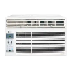
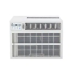
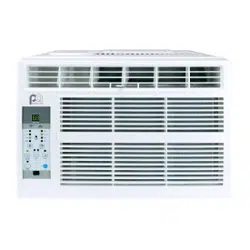
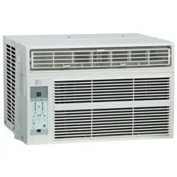
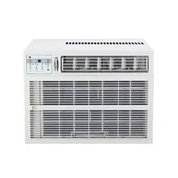
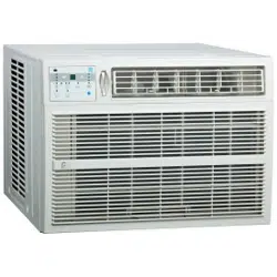
WINDOW
AIR CONDITIONER
FOR MODEL:
4PAC15000
4PAC18000
4PAC25000
Before using your air conditioner, please
read this manual carefully and keep it for
future reference, along with your receipt.
Specification and performance data is subject to change without notice.
Printed in China
PA/User4PAC15000_4PAC18000_4PAC25000/10162017
USER MANUAL

For your own records, please attach a copy of your sales receipt to this manual and complete the following:
Model Number: _____________________________________ Serial Number: _______________________________________
Purchase Date: ____________________________________ Store Purchased: _____________________________________
Installation Date: ___________________________________ Installation Co.: _______________________________________
Installer Name: _____________________________________ Installer Phone No.: ___________________________________
CONSUMER PRODUCT INFORMATION
SAFETY PRECAUTIONS ...................................................................1
IMPORTANT SAFETY INSTRUCTIONS ...........................................3
INSTALLATION INSTRUCTIONS .....................................................4
WINDOW MOUNTING INSTALLATION INSTRUCTIONS .......6
THRU-THE-WALL INSTALLATION INSTRUCTIONS ..................11
MASONRY CONSTRUCTION ..........................................................12
NORMAL SOUNDS ...........................................................................13
AIR CONDITIONER FEATURES .......................................................13
CARE AND CLEANING ....................................................................16
TROUBLESHOOTING ....................................................................... 17
CONTENTS
This manual provides the information needed for proper use and mainte-
nance of this air conditioner. Basic preventative care can help extend the life
of this unit. The “Troubleshooting” section in this manual contains a chart
with solutions to the most common problems. Referring to this section may
save time and prevent the need for a service call in the event of a problem.
CAUTION
● Contactanauthorizedservicetechnicianforrepairormaintenanceofthisunit.
● Ifnecessary,contactaninstallerforinstallationofthisunit.
● Theairconditionerisnotintendedforusebyyoungchildrenwithoutsupervision.Youngchildrenshouldbesupervised
to ensure that they do not play with the air conditioner.
● Disabledpersonsmayrequireassistancewithsetup.
● Ifthepowercordistobereplaced,replacementworkshouldbeperformedbyauthorizedpersonnelonly.
● Installationandrepairworkmustbeperformedinaccordancewiththenationalwiringstandardsbyauthorized
personnel only.
● Donotoperateyourairconditionerinawetroomsuchasabathroomorlaundryroom.
NOTE:Alltheillustrationsinthismanualareforexplanationpurposesonly.Unitpurchasedmaybeslightlydierent.
Thedesignandspecicationsaresubjecttochangewithoutpriornoticeforproductimprovement.ContactConsumer
Services as 844-4PA-AIRE (844-472-2473) for details.
1
WARNINGS
Plug in power cord properly. Failuretodosomaycauseelectricshockorredueto
excess heat generation.
DO NOT operate or stop the unit by inserting or pull-
ing out the power plug directly from the wall.
Doingsomaycauseelectricshockorredueto
heat generation.
DO NOT use a damaged power cord.
Doingsomaycauseelectricshockorre.Ifthepower
cord is damaged, it must be replaced by the manufactur-
eroranauthorizedservicecenterorasimilarlyqualied
personinordertoavoidahazard.
DO NOT modify power cord length or share the
outlet with other appliances.
Doingsomaycauseelectricshockorredueto
heat generation.
DO NOT operate with wet hands or in
damp environment.
Doingsomaycauseelectricshock.
DO NOTdirectairowdirectlyatroomoccupants.
This could cause health issues.
Alwaysensureeectivegrounding. Incorrectgroundingmaycauseelectricshock.
DO NOT allow water to run into electric parts.
Doingsomaycausefailureofmachineorelectricshock.
Alwaysinstallcircuitbreakerandadedicated
power circuit.
Incorrectinstallationmaycausereandelectricshock.
Always unplug the unit if strange sounds, smell or
smokecomesfromtheunit.
Failuretodosomaycausereandelectricshock.
DO NOTusethesocketifitislooseordamaged.
Doingsomaycausereandelectricshock.
DO NOT open the unit during operation.
Doingsomaycauseelectricshock.
DO NOTuserearmsnearunit.
Doingsomaycausere.
DO NOT use the power cord close to
heating appliances.
Doingsomaycausereandelectricshock.
DO NOT disassemble, modify, or drill holes into
the air conditioner.
Doingsomaycausefailureandelectricshockandvoid
the manufacturer’s warranty.
Ventilate room before operating air conditioner if
thereisagasleakfromanotherappliancesuchas
a stove.
Failuretodosomaycauseexplosion,reandburns.
DO NOT
usethepowercordnearammablegasor
combustibles,suchasgasoline,benzene,thinner,etc.
Doingsomaycauseanexplosionorre.
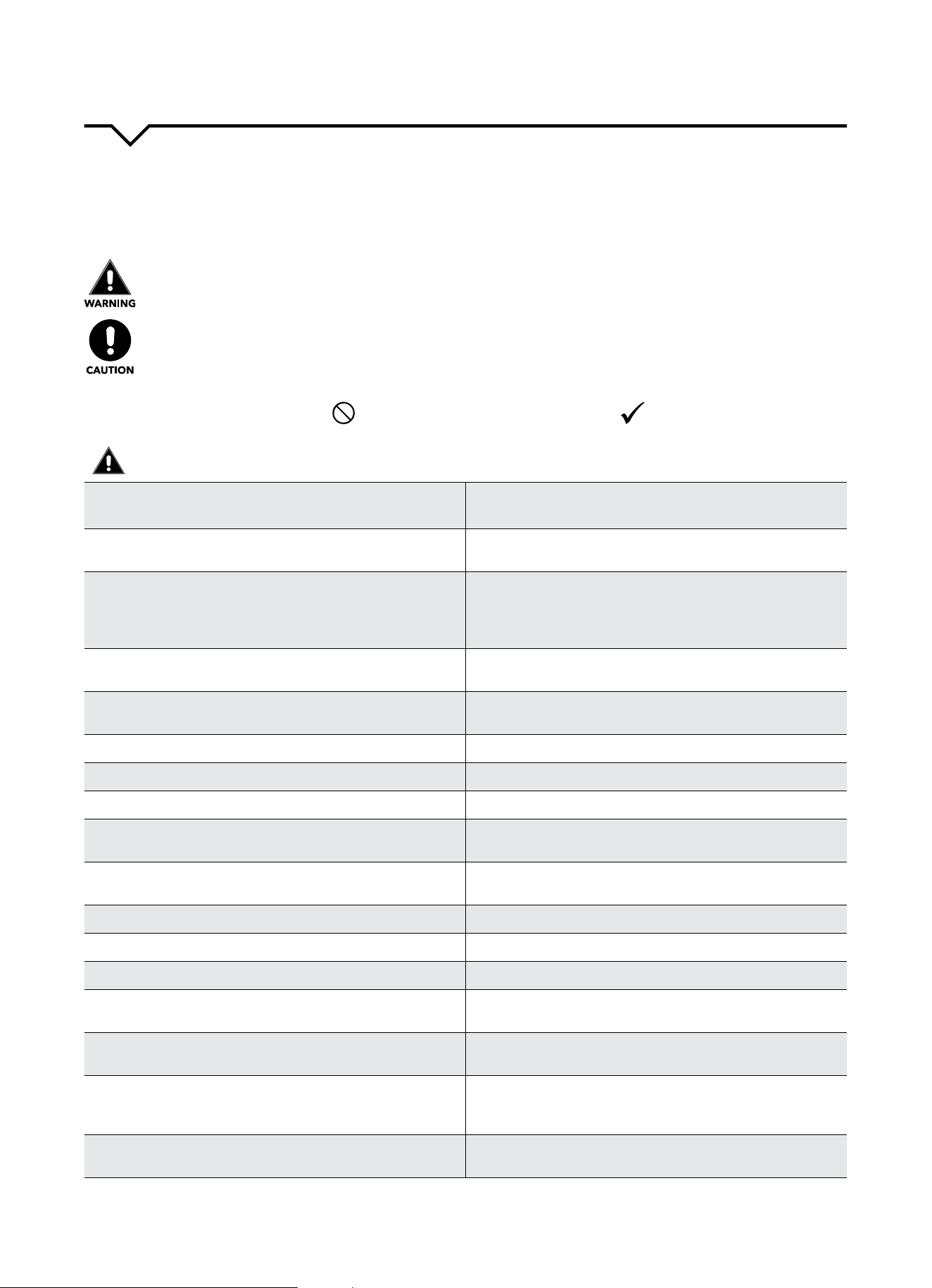
READ SAFETY PRECAUTIONS BEFORE INSTALLATION
Topreventinjurytotheuserorotherpeopleandpropertydamage,thefollowinginstructionsmustbefollowed.
Incorrectoperationduetoignoringofinstructionsmaycauseharmordamage.Theseriousnessisclassiedbythe
following indications.
THIS SYMBOL INDICATES THAT IGNORING INSTRUCTIONS MAY CAUSE
DEATH OR SERIOUS INJURY.
NEVER DO THIS.OTHER SYMBOLS: ALWAYS DO THIS.
THIS SYMBOL INDICATES THAT IGNORING INSTRUCTIONS MAY CAUSE
MODERATE INJURY TO YOUR PERSON, OR DAMAGE TO YOUR UNIT OR
OTHER PROPERTY.
SAFETY PRECAUTIONS

2
CAUTIONS
Whenremovingairlter,DO NOT touch metal parts of
the unit.
Doingsomaycauseaninjury.
DO NOT clean with water.
Water may enter the unit and degrade the insulation,
causinganelectricshock.
Ensure proper ventilation, especially in rooms with a
stove or other appliances.
Failure to do so may result in an oxygen shortage.
Unitandcircuitbreaker/fusemustbeswitchedOFF
when cleaning.
CleaningunitwhenpowerisONmaycausereand
electricshockandmaycauseaninjury.
DO NOT put a pet or house plant where it will be ex-
posedtodirectairow.
Thiscouldinjurethepetorplant.
Use ONLY as intended. This unit is NOT intended to preserve precision devic-
es,food,pets,plants,andartobjects.Itmaycause
deteriorationofquality,etc.
Stop operation and close the window in severe
storms or hurricanes.
Operationwithwindowsopenmaycausemoistureto
enter the room.
Hold the plug by the head of the power plug when
takingitout.
Failuretodosomaycauseelectricshock
and damage.
If unit will not be used for a long period of time,
unplug or turn OFF main power switch.
Leavingpoweronmaycauseunitfailureorre.
Do not place obstacles around air-inlets or inside of
air-outlet.
Obstaclesmaycauseappliancefailureoraccident.
Periodicallycheckinstallationbracketfordamage. Prolonged exposure to outdoor elements may cause
damagetoinstallationbracket,causingunittofall.
Alwaysinsertlter(s)securely.Cleanlter(s)AT LEAST
onceeverytwoweeks.
Operationwithoutsecurelyinstalledltersmay
causefailure.Adirtyltercancausetheunittonot
runeciently.
Use only a soft cloth to clean the unit. Cleaners or detergents may change the color or
scratch the surface of the unit.
Usecautionwhenunpackingandinstalling. Sharpedgescouldcauseinjury.
NEVERdrinkwaterdrainedfromairconditioner.
Water from unit contains contaminants and could
cause illness.
DO NOTplaceheavyobjectsonthepowercordand
always ensure that the cord is not compressed.
Thereisdangerofreorelectricshock.
If water enters the unit’s electrical components, turn
theunitoatthepoweroutletandswitchothecir-
cuitbreaker.Isolatesupplybytakingthepower-plug
outandcontactaqualiedservicedtechnician.
Thereisdangerofelectricshock.
3
IMPORTANT SAFETY INSTRUCTIONS
NOTE
:
The power supply cord with this air
conditioner contains a current detection
devicedesignedtoreducetherisk
ofre.Pleaserefertothesection
“OperationofCurrentDevice”(below)
for details. In the event that the power
supply cord is damaged, it cannot be
repaired. It must be replaced by an
authorizedrepairtechnicianwithacord
from the Product Manufacturer.
WARNING
Avoidrehazardsorelectricshock.DO
NOT use an extension cord or an adapter
plug. DO NOT remove any prong from the
power cord.
OPERATION OF
CURRENT DEVICE:
The power supply cord contains a
current device that senses damage
to the power cord. To test your power
supply cord, do the following:
1. Plug in the air conditioner.
2. The power supply cord will have
TWObuttonsontheplughead.Press
theTESTbutton.Youwillnoticea
clickastheRESETbuttonpopsout.
3. Press the RESET button. Again,
youwillnoticeaclickasthe
button engages.
4. The power supply cord is now
supplyingelectricitytotheunit.(On
some products this is also indicated
by a light on the plug head.)
WARNING
FORYOURSAFETY:Donotstoreorusegasolineorotherammable
vaporsandliquidsinthevicinityofthisoranyotherappliances.
WARNING - PREVENT ACCIDENTS
Toreducetheriskofre,electricalshock,orinjurytopersonswhenusing
your air conditioner, follow basic precautions, including the following:
● Besuretheelectricalserviceisadequateforthemodelyouhave
chosen. This information can be found on the serial plate, which is
located on the side of the cabinet and behind the grille.
● Iftheairconditioneristobeinstalledinawindow,youwillprobably
wanttocleanbothsidesoftheglassrst.Ifthewindowisatriple-
tracktypewithascreenpanelincluded,removethescreencompletely
before installation.
● Besuretheairconditionerhasbeensecurelyandcorrectlyinstalled
according to the installation instructions in this manual.
●
Save this manual for possible future use in removing or installing this unit.
● Whenhandlingtheairconditioner,becarefultoavoidcutsfromsharp
metalnsonfrontandrearcoils.
WARNING - ELECTRICAL INFORMATION
The complete electrical rating of your new room air conditioner is
statedontheserialplate.Refertotheratingwhencheckingthe
electricalrequirements.
● Besuretheairconditionerisproperlygrounded.Tominimizeshock
andrehazards,propergroundingisimportant.Thepowercordis
equippedwithathree-pronggroundingplugforprotectionagainst
shockhazards.
● Yourairconditionermustbeusedinaproperlygroundedwall
receptacle.Ifthewallreceptacleyouintendtouseisnotadequately
groundedorprotectedbyatimedelayfuseorcircuitbreaker,havea
qualiedelectricianinstalltheproperreceptacle.
● Ensurethereceptacleisaccessibleaftertheunitinstallation.
● Donotrunairconditionerwithoutsideprotectivecoverinplace.This
could result in mechanical damage within the air conditioner.
● Donotuseanextensioncordoranadapterplug.
NOTE
:
Donotusetheplugtoturntheunitonoro.
● AlwaysmakesuretheRESETbuttonispushedinforcorrectoperation.
● ThepowersupplymustbereplacedifitfailsresetwheneithertheTEST
button is pushed or it cannot be reset.
● Ifpowersupplycordisdamaged,itcannotberepaired.Pleasecall
Consumer Services at 844-472-2473 to assist with replacement.
NOTE: This air conditioner is designed to be operated under the
following conditions:
Cooling
Operation
Outdoor Temp:
64–109°F/18–43°C
(64–125°F/18–52°Cforspecialtropicalmodels)
Indoor Temp:
62–90°F/17–32°C
Performance may be reduced outside of these operating temperatures.
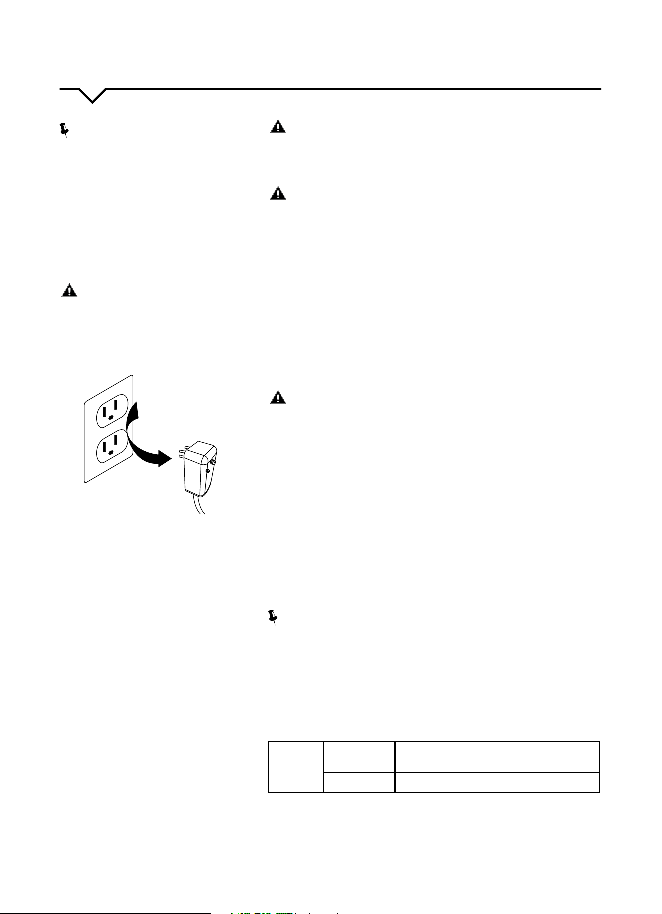
Grounding Type
Wall Receptacle
Do not, under any
circumstances, cut,
remove, or bypass the
ground prong.
Power supply cord
with 3-prong grounding
plug and current
detection device
4
BEFORE YOU BEGIN
Read these instructions completely and carefully.
IMPORTANT- Save these instructions.
IMPORTANT-Observeallgoverningcodesand
ordinances.
Note to Installer- Be sure to leave these instructions with
the Consumer.
Note to Consumer- Keep these instructions for future
reference.
Skill level-Installationofthisappliancerequiresbasic
mechanicalskills.
Completion time- Approximately 1 hour.
We recommend that two people install this product.
Proper installation is the responsibility of the installer.
Product failure due to improper installation is not
covered under the Warranty.
YouMUSTuseallsuppliedpartsanduseproper
installation procedures as described in these
instructions when installing this air conditioner.
CAUTION
Do not, under any circumstances, cut or remove the
third (ground) prong from the power cord.
Do not change the plug on the power cord of the air
conditioner.
Aluminum house wiring may present special problems-
consultaqualiedelectrician.
When handling unit, be careful to avoid cuts from sharp
metaledgesandaluminumnsonfrontandrearcoils.
REQUIRED TOOLS/HARDWARE
● Pencil
● Level
● Tapemeasure
● Socketwrenches
● Phillipsscrewdriver
● Adjustablewrenchorpliers
● Largeatbladescrewdriver
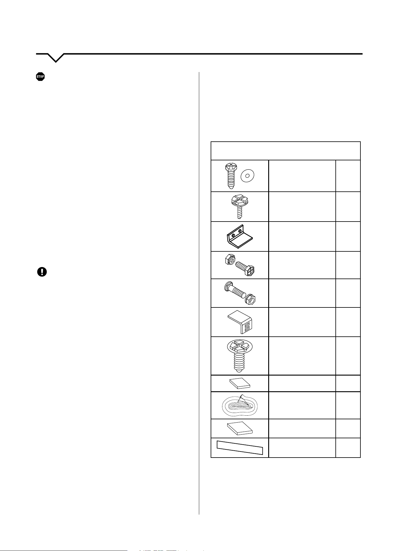
HARDWARE
(Included - Packed with the Unit)
7/16inchlocking
screwandatwasher
for window panels
2 ea.
3/4(or1/2)inchLong
Hex-head Screw
4
SafetyLock
1
3/4inchLongFlat
Head Bolt and
Locknut
4 ea.
1/2inchLongScrew
andLocknut
2 ea.
SillAngleBracket
2
Longhex-headlocking
screw for tape angle,
sideretailer5/16inch
long
10
Foam insert
2
Window sash seal
foam
1
Insulation Panels
2
Weatherstripping(10″
x3/4″x1/12″)
5
INSTALLATION INSTRUCTIONS
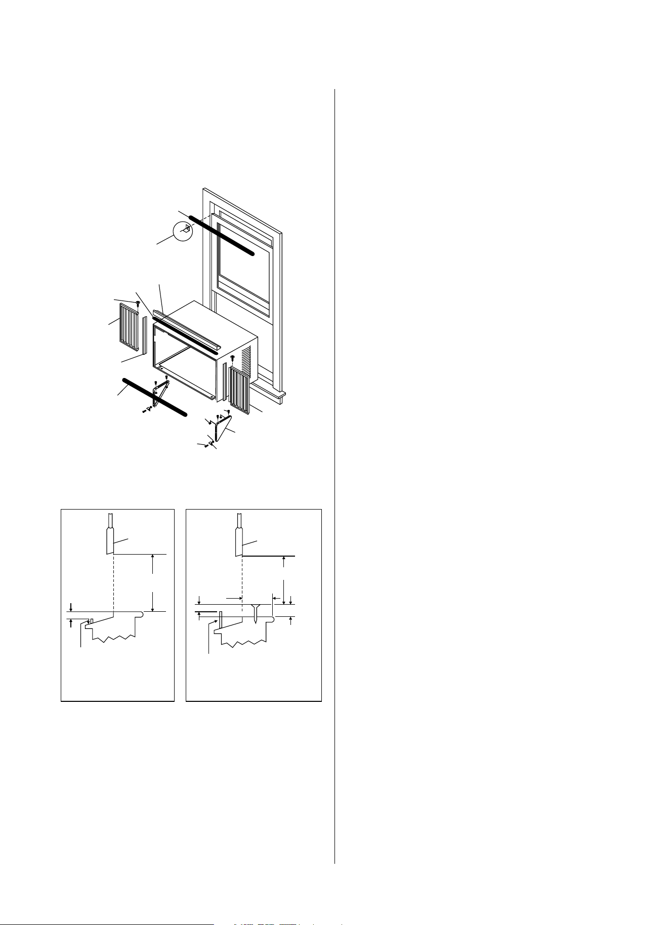
5
Please read ALL instructions before installing. It is
recommended that two people install this product.
Ifanewelectricaloutletisrequired,havetheoutlet
installedbyaqualiedelectricianbeforeinstallingthe
air conditioning unit.
Window Sash Seal
Top Angle
Foam Gasket
Side Retainer
Locknut
Safety Lock and
3/4″ (or 1/2″)
Long Hex Head Screw
1/2″ Long
Screw and
Locknuts
Washer Head
Locking Screw
Seal Bottom
Rail to Unit
Frame
Assembly
(Left)
Frame Assembly
(Right)
3/4″ Long
Flat Head
Bolt
Sill Angle
Bracket
Window Support
Bracket
FIG. A
SASH
SASH
19″ MIN.
19″ MIN.
1/2″ MIN.
1/2″ MIN.
1/2″ MIN.
Board
thickness
as required
along entire
stool. Fasten
with 2 Nails
or Screws.
Storm window
frame or other
obstruction
Storm window
frame or other
obstruction
FIG. B FIG. C
PRELIMINARY INSTRUCTIONS
Do the following before installing the unit. (See
illustrations on left.)
Checkdimensionsofyourunittodetermineproper
window dimensions:
Unit Height: 17
5
/8 or 18
5
/8
Unit Width: 23
5
/8 or 26
1
/2
Min. Window Height: 18
1
/2 or 19
1
/2
Min. Window Width: 28 or 31
Max. Window Width: 40
1
/2 or 42
1. CHECK WINDOW OPENING SIZE — The mounting parts
furnished with this air conditioner are made to install
in a wooden sill, double-hung window. The standard
partsareforwindowdimensionslistedabove.Open
sash to a minimum of 19 in. (483 mm). See Fig. B .
2. CHECK CONDITION OF WINDOW — All wood parts of
windowMUSTbeingoodshapeandabletormly
holdtheneededscrews.Ifnot,makerepairsbefore
installing unit.
3. CHECK YOUR STORM WINDOWS — If your storm
windowframedoesnotallowtheclearancerequired,
correct by adding a piece of wood, as shown in
Fig. C, or by removing storm window while room air
conditioner is being installed.
4. CHECK FOR ANYTHING THAT COULD BLOCK AIRFLOW —
Checkareaoutsideofwindowforthingssuchas
shrubs, trees, or awnings. Inside, be sure furniture,
drapes,orblindswillnotstopproperairow.
5. CHECK THE AVAILABLE ELECTRICAL SERVICE — Power
supply MUST be the same as that shown on the
unit serial nameplate. Power cord is 48 inches long.
Besureyouhaveanoutletnear.DONOTusean
extension cord.
6. CAREFULLY UNPACK THE AIR CONDITIONER — Remove
allpackagingmaterial.Covertheoorduring
installation to prevent damage. Two people should be
used to move and install unit.
6
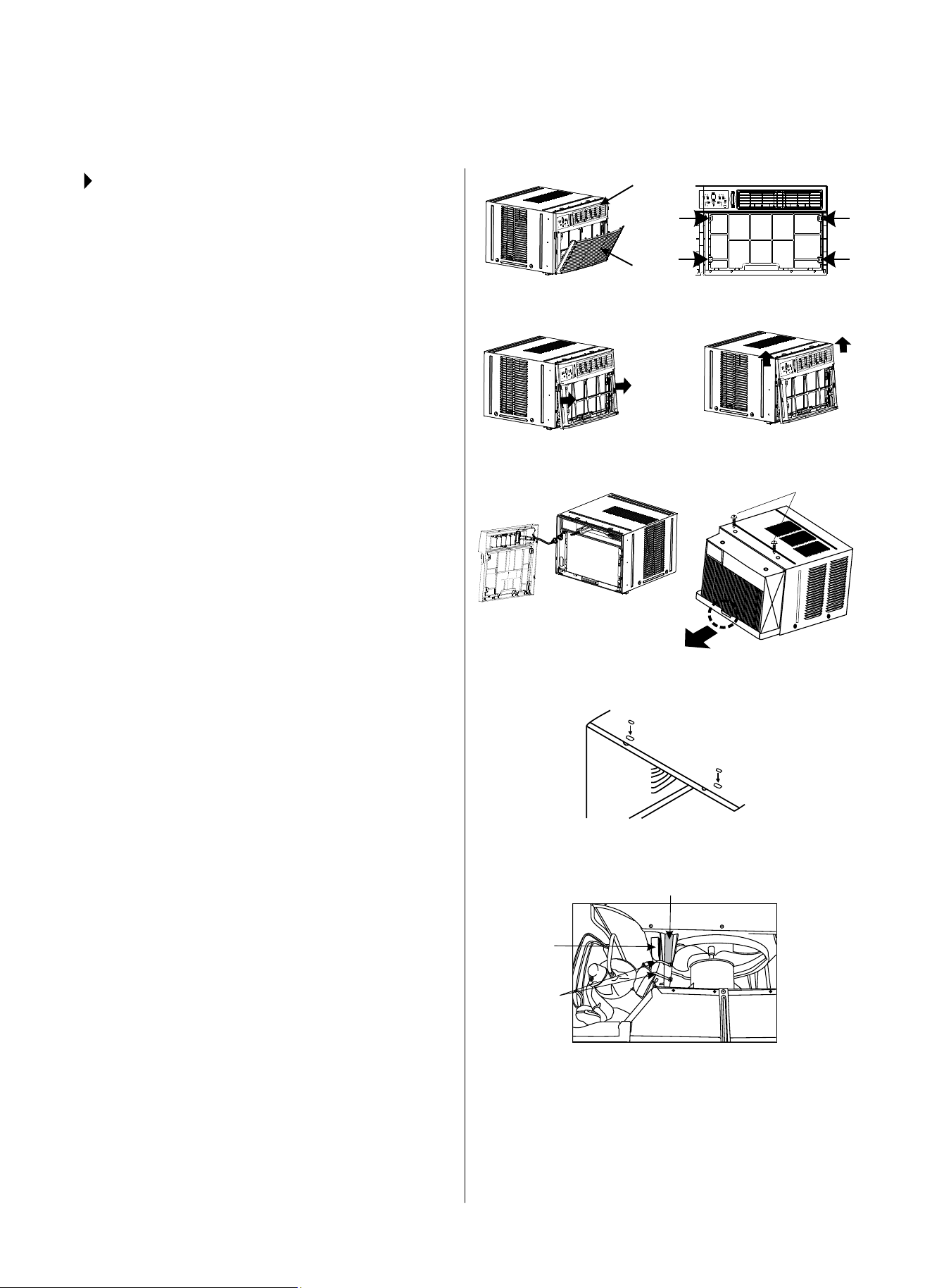
STEP 1:
REMOVE CHASSIS
1. Pulldownfrontgrilleandremovelter.
(See Fig. 1.)
2. Lift front grille upwards and place to one side.
3. Locate and remove the four front screws. These
screws will be needed to re-install the front panel
later. (See Fig. 2.)
4. Push metal cabinet side and pull on plastic frame
to release plastic tabs on each side of front panel.
(See Fig. 3.)
5. Gentlyliftfrontpanelounit.
(See Fig. 3A.)
6. Disconnect the connector plug of the display
panel from the unit and place front panel to one
side. (See Fig. 4.)
7. Remove shipping screws from top of unit. (See
Fig. 5.)
8. Hold the cabinet while pulling on the base handle,
and carefully remove the unit.
9. Add two foam inserts to holes in top of cabinet
where shipping screws were removed from.
(See Fig. 6.)
10. Yourunitmaycomewithinternalpackaging
(shippingpackaging,plasticties,grayfoam
padding,asshowninFig.7).Thispackaging
MUST be removed prior to installing the air
conditionerbackintothecabinet.
DO NOT LIFT, PULL, OR REMOVE ANY EXPANDED
POLYSTYRENE (FOAM) FROM INSIDE OF THE AIR
CONDITIONER. IT IS NOT PACKING MATERIAL.
WINDOW MOUNTING INSTALLATION INSTRUCTIONS
FIG. 1
FIG. 4
FIG. 3
FIG. 2
FIG. 5
FIG. 6
FIG. 7
FIG. 3A
Shipping
Packaging
Shipping
Screws
Plastic Ties
Front Grille
Front Panel
Gray Foam
Padding
7
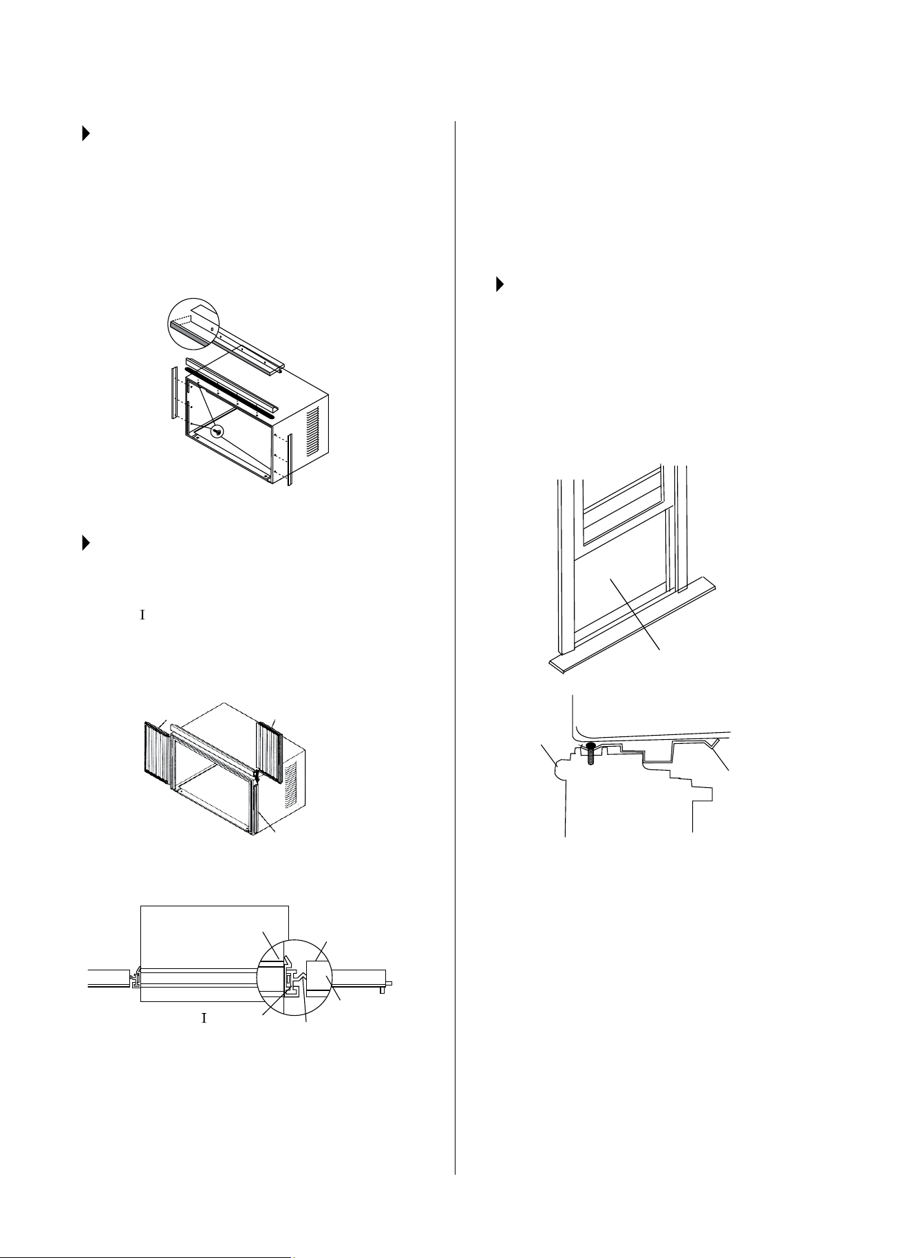
STEP 2:
INSTALL TOP ANGLE AND
SIDE BRACKET
1. Attachfoamgaskettotopangleaboveholes,as
shown in Fig. 6 on previous page.
2. Install top angle and side retainers to cabinet, as
shown in Fig. 8. (10 screws)
FIG. 8
5/16″ long
hex-head
STEP 3:
ASSEMBLE ACCORDION PANELS
1. Placecabinetonoor,abench,oratable.
2. Slide “
”sectionofwindowllerpanelintoside
retainer on the side of the cabinet. (See Fig. 9 and
Fig. 10.) Do this on both sides.
FIG. 9
FIG. 10
Accordion
Panel
Air Conditioner
Cabinet
Top
View
Plastic
Frame
Locking
Screw
Hole
Accordion
Panel
“
“ Section
Side Retainer
Plastic
Frame
3. Inserttopandbottomlegsofwindowllerpanel
frame into channel in the top angle and bottom rail.
Do this on both sides.
4. Insertwasherheadlocking7/16″screws(2)into
holesintoplegofllerpanelframe.(Seestep6on
next page.) Do not totally tighten. Allow leg to slide
freely. Screws will be tightened after step 6.
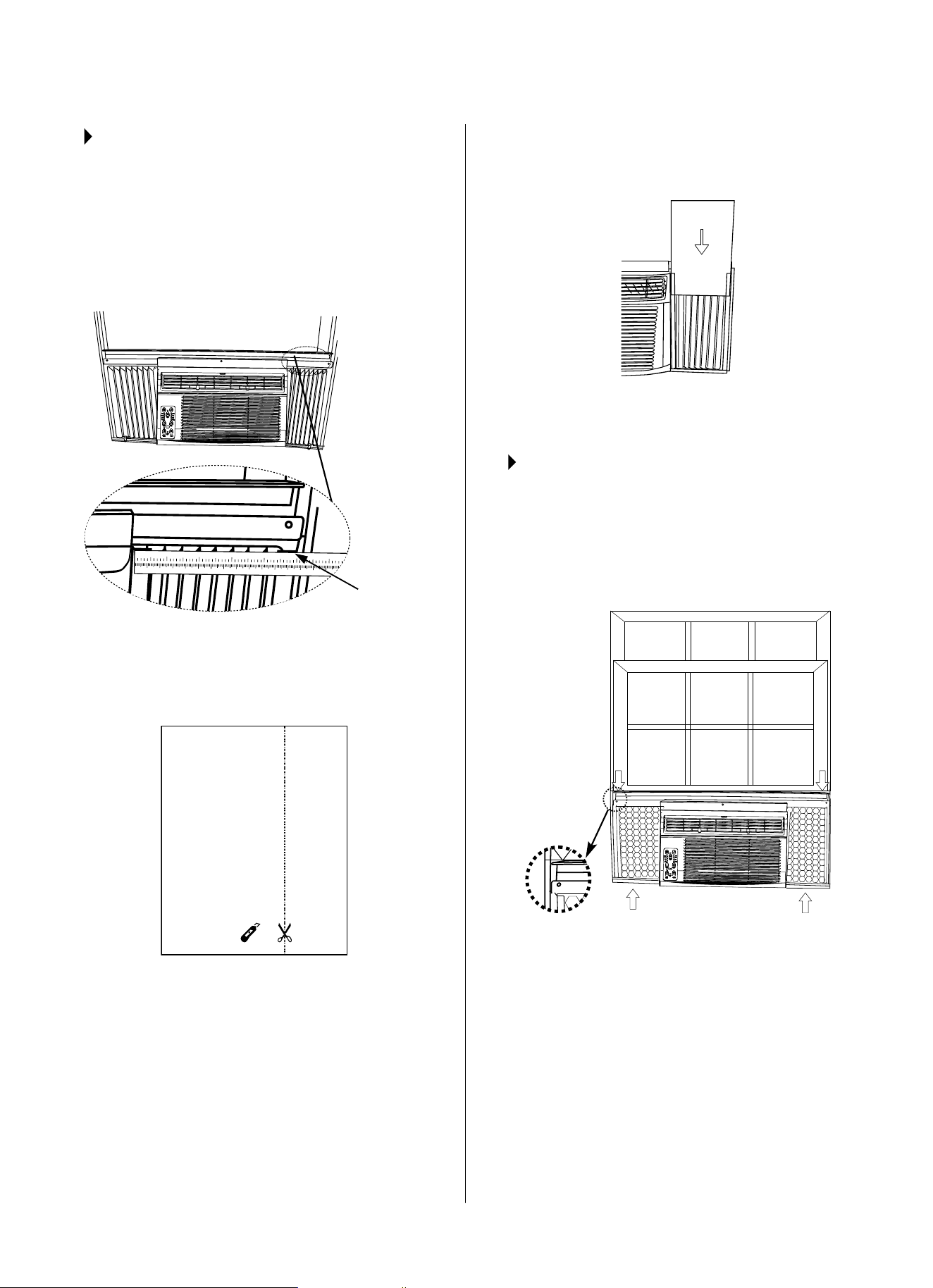
STEP 4:
PLACE CABINET IN WINDOW
1. Openwindowandmarkcenterofwindowsill.
(Fig. 11)
2. Place cabinet in window with bottom sill angle
rmlyseatedoverwindowsillasshown.Bring
window down temporarily behind top angle to hold
cabinet in place. (Fig. 12)
FIG. 12
FIG. 11
Sill
Angle
Sill
3. Shift cabinet left or right as needed to line up
centerofcabinetoncenterlinemarkedonsill.
4. Fasten cabinet to window sill with 2 screws into
holes.(Youmaywishtopre-drillpilotholes.)
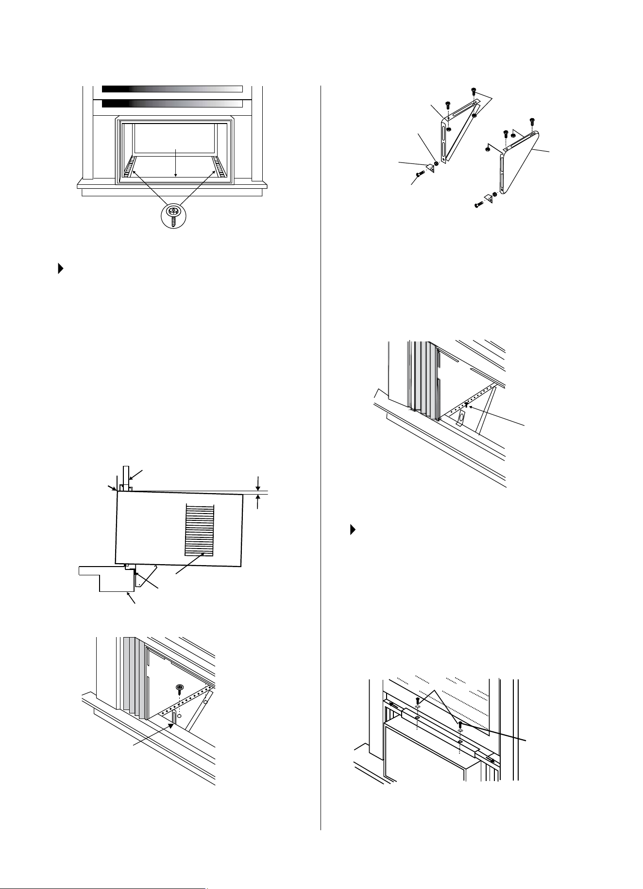
5. Add bottom rail seal over screw to window sill.
(See Fig. 13 on next page.)
8
FIG. 13
Bottom
Rail Seal
3/4″ (or 1/2″) long
Hex-head Screw
STEP 5:
INSTALL SUPPORT BRACKET
1. Holdeachsupportbracketushagainstoutsideof
sill & tighten to bottom of cabinet, as shown in Fig.
15A.Markbracketsattoplevelofsillandremove.
2. Assemblesillanglebrackettosupportbracketsat
themarkedposition.(SeeFig.15B.)Handtighten,
but allow for any changes later.
NOTE:Checkthatairconditioneristiltedbackabout
1½ʺto1⅝ʺ (tilted about 3º to 4º downward toward
the outside). If, after proper installation, condensation
doesnotdrainfromtheoverowdrainholeduring
normaluse,adjustslope.(Fig14)
FIG. 14
FIG. 15A
Mark
About 1
1
/2″
to 1
5
/8″
Window Sash
Side Louvers
Sill Angle Bracket
Window Sill
Measure from the
cabinet edge.
5
FIG. 15B
Right
Left
Locknut
1/2″ Log Screws
and Locknuts
2 Each Required for
Each Support Bracket
Sill Angle
Bracket
Flat Head
Bolt
3. Installsupportbrackets(withsillanglebrackets
attached) to correct hole in bottom of cabinet, as
shown in Fig. 16.
4. Securely tighten all 6 bolts.
1/2″ Long
Screws and
Locknuts
FIG. 16
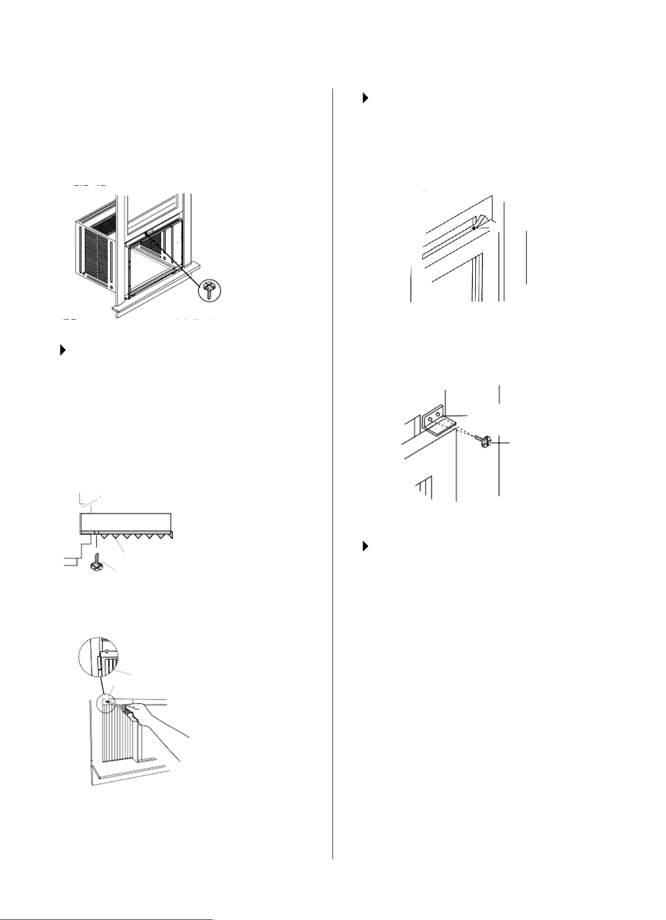
STEP 6:
EXTEND WINDOW
ACCORDION PANELS
1. Carefully raise window to expose accordion panel
lockingscrews.Loosenscrewssoaccordion
panels slide easily.
2.Extendpanelstollwindowopeningcompletely.
Tightenlockingscrewsontop(Fig.17A).
3. Close window behind top angle.
Locking Screw
7/16″ Locking
Screw and
Washer
FIG. 17A
9
4. Attachthetopangletowindowframe:Usea3/32″
drill bit to drill one hole through the hole in the
middle of top angle into the window frame, and
driveone3/4″(or1/2″)HEX-HEADlockingscrew
through hole in the middle of top angle into the
window frame, as shown (Fig. 17B).
3/4″ (or 1/2″) long
hex head screw
FIG. 17B
STEP 7:
ATTACH ACCORDION PANELS TO
WINDOW FRAME
1. Extend the accordion panels out against the
window frame.
2. Use1/8″drillbittodrillastarterholethroughthe
holeinthetoplegofeachwindowllerpaneland
into the window sash. (Fig. 18A and Fig. 18B.)
Connectwithone3/4″(or1/2″)longhex
head screw.
A. 3/4″ (or 1/2″)
long hex head
screw
B. Left-hand
Window Filler
Panel Top Leg
C. Window channel
A. 3/4″ (or 1/2″)
long hex head
screw
A
A
B
C
Window Sash
Weather Seals
FIG. 18A
FIG. 18B
STEP 8:
INSTALL WINDOW SASH SEAL AND
SAFETY LOCK
1. Trimsashsealtotwindowwidth.Insertinto
space between upper and lower sashes. (Fig 19A)
Window Sash Seal
FIG. 19A
2. Attachrightanglesafetylock.(Fig.19B)
FIG. 19B
Safety Lock
3/4″ (or 1/2″)
long hex head
screw
STEP 9:
INSTALL CHASSIS INTO CABINET
AND INSTALL FRONT TO UNIT
1. Lift air conditioner and carefully slide into cabinet,
leaving 6 inches protruding.
2. DONOTpushoncontrolsornnedcoils.
3. Besurechassisisrmlyseatedtowardsrearof
cabinet.
4. Installation of front is the reverse of removal
outlined in Step 1.
10
STEP 10:
INSTALL INSULATION PANELS
Inordertominimizeairleaksandensureoptimal
insulation, it is necessary to install the included
insulation panels to the accordion panels. Follow the
4 steps in these instructions:
STEP 10.1: After the unit is installed in the window,
measure the inner width of one of the accordion
panels, as shown in Fig. 20.
1 2 3 4 5 6 7 8 9 10 11 12 13
14 15 16 17
1
2 3 4 5 6
STEP 10.2:Markalineononeoftheprovided
insulation panels, matching the measured width in
Step 10.1; Cut the insulation panel along the line
(Fig. 21).
or
STEP 10.3:Slidetheinsulationpanelyoujustcut
into the accordion panel (curtain). The side of the
insulation panel with the pattern on it should face
indoors. (Fig. 22)
STEP 10.4: Repeat on other side with the second
insulation panel.
STEP 11:
INSTALL WEATHER STRIPPING
Inordertominimizeairleaksbetweentheroomair
conditioner and the window opening, install weather
stripping into any gaps as you see necessary by
trimming the weather stripping to the desired length,
peelingotheprotectivebackingandllingthese
gaps. (Fig. 23)
FIG. 20
FIG. 21
Measure
the inner
width of
one of the
accordion
panels.
FIG. 22
FIG. 23
11
THRU-THE-WALL INSTALLATION INSTRUCTIONS
STEP 1:
SELECT WALL LOCATION
The air conditioner has a slide-out chassis so that it can be
installedthroughanoutsidewallasspeciedbelow:
Max.WallThickness:12″or10″
IMPORTANT:Sidelouversmustneverbeblocked.
NOTE:AllpartsneededforThru-The-WallInstallationare
provided except a wood frame, shims, and 10 wood screws
(#10-1 long minimum).
Select a wall surface that:
• Doesnotsupportmajorstructuralloadssuchastheframe
construction at ends of windows, under truss-bearing
points, etc.
• Doesnothaveplumbingorwiringinside.
• Isnearexistingelectricaloutlets,orwhereanotheroutlet
can be installed.
• Faces(andisnotblocked)theareatobecooled.
• Allowsunblockedairowfromrearsidesandend(outside)
of installed air conditioner.
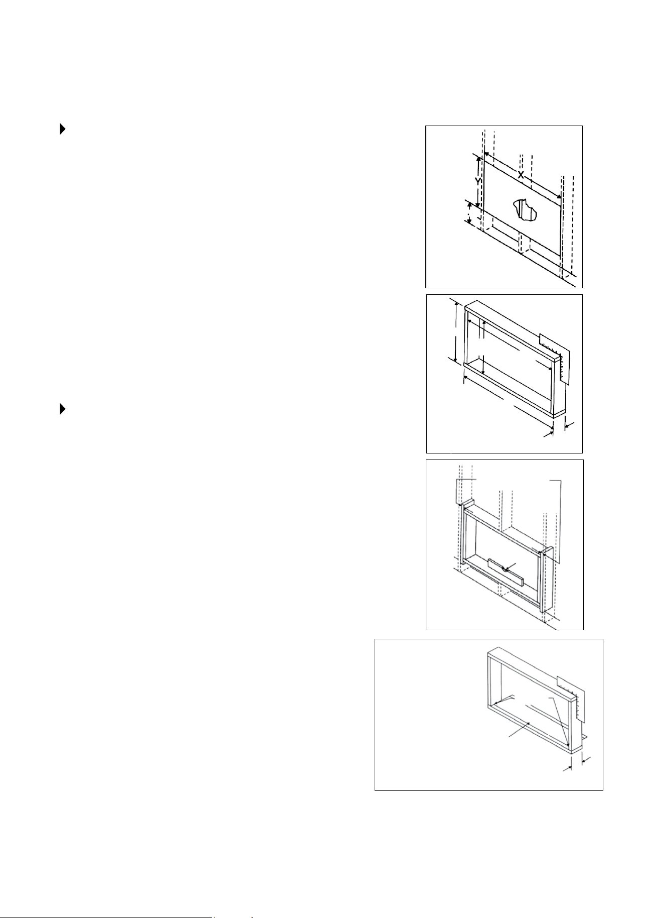
STEP 2:
PREPARE WALL
1. Preparewallinframeconstruction(includingbrickand
stuccoveneer).Workingfrominsidetheroom,ndwall
stud nearest the center of area where air conditioner will be
installed(bysoundingwall,orbymagneticallyndingnails.)
2. Cutorknockoutaholeoneachsideofcenterstud.
3. Measure between inside edges of every other stud as
shown in Fig. 1.
NOTE:Carefullymeasureandcutanopeningwiththe
following dimensions, depending on your model. (See Fig. 1
and 2.)
WIDTH“X”= insidemodelwidthplustwicethethicknessof
framing material used.
HEIGHT“Y”= insidemodelheightplustwicethethicknessof
framing material used.
InsideFrameHeight187/8″(47.9cm)or18″(45.7cm)
InsideFrameWidth:263/4″(67.9cm)or237/8″(60.6cm)
4. Build wooden frame with the INSIDE dimensions of
your model listed above. (Be sure to measure twice for
accuracy.) Frame depth should be the same as wall
thickness.Fillinthespacefromtheopeningtothestuds
with wood spacers. (See Fig. 3.)
5. Nailframespacers,withfrontushwithdrywall.
X
Y
FIG. 1
FIG. 2
FIG. 3
FIG. 4
Nail
Spacers to Studs
Caulk as
required
Aluminum
Flashing Over
Bottom of
Frame
NOTE:
If wall thickness is
8.5″ or more, add
aluminum flashing
over bottom of frame
opening to assure no
water can enter area
between inner and
outer wall.
Level
Inside
Frame
Height
Inside
Frame
Width
Up to
8.5″
Over
8.5″
12
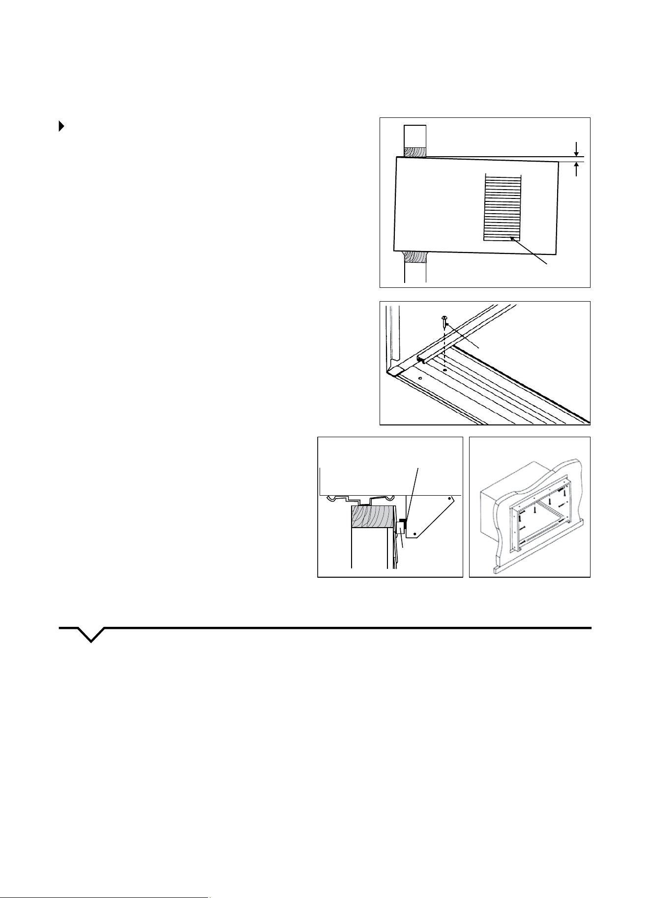
STEP 3:
PREPARE AND INSTALL CABINET
1. Slidechassisfromcabinet.ReferbacktoStep1of
Window Mounting section.
2. Place cabinet into opening with bottom rail resting
rmlyonbottomboardofwoodenframe.
3. Position cabinet to achieve proper slope for water
removal. (See Fig. 5.)
4. Secure bottom rail to wooden frame with two large
woodscrews1″(2.5cm)longusingthetwoholesin
the bottom of the channel resting on frame. (See
Fig. 6.)
Refer to Step 5 of Window Mounting section for
assemblyofsupportbrackets.Awoodenstripnailedto
theoutsidewallshouldbeusedinconjunctionwithsill
supportanglebrackets.(SeeFig.7.)
5. Screw or nail cabinet wooden frame using shims, if
frameisoversized,toeliminatedistortion.(SeeFig.
8.) Remember to maintain proper slope, as described
in Step 3.
6. Install chassis into cabinet by following all directions
in Step 9 of Window Mounting section.
OPTIONAL:Caulkingandinstallationoftrimoninterior
wallmaybedone.Youcanbuywoodfromyourlocal
lumberorhardwaresupply.Ontheoutside,caulk
openings around top and sides of cabinet, and all sides
of wood sleeve to the opening.
NOTE: See Fig. 11 of Window Mounting Instructions for
bottom rail seal location.
NOTE: Check that air
conditioner is tilted back
about 1-1/2″ to 1-5/8″
(3° to 4° downward
toward the outside). If,
after proper installation,
condensation does not
drain from the overflow
drain hole during normal
use, adjust slope.
MASONRY CONSTRUCTION
1. Cut or build a wall opening in the masonry wall
similar to the frame construction (refer to Step 2 of
Thru-The-WallInstallationforwallthicknessgreater
than 8½″).
2. Secure cabinet in place using masonry nails or the
right masonry anchor screws. (Another way to do this
is to build an in-between frame of 2x4’s as shown
instep2ofThru-The-WallInstallationbutmakeit
double framed on either side and install between
masonry wall opening and cabinet. Frame must be
securely anchored to masonry wall opening.) This
way gives very good louver clearance on either side
of the cabinet.
3. Install a lintel to support masonry wall above
cabinet.Existingholesincabinetcanbeusedand/
or additional holes can be drilled to fasten cabinet
at various positions. Be sure that side louver
clearance is in accordance with Step 1 of Masonry
Construction.
4. Installexteriorcabinetsupportbracketsasshownin
Step3ofThru-The-WallInstallation.Caulkorash
if needed to provide a weather-tight seal around top
and sides of cabinet.
5. To complete installation, apply wood trim molding
aroundroomsideprojectionofcabinet.
NOTE:Afterinstalling,makesuretheairconditioneris
tilted 3-4° to the outside to allow water drainage and
perfectcoolingeciency.
FIG. 5
FIG. 7
FIG. 8
FIG. 6
3 ~ 4°
Side Louvers
1″ Long Wood Screw
Sill angle bracket
Wooden Strip
Support
bracket
13
NORMAL SOUNDS
AIR CONDITIONER FEATURES
Sleep
Check
Filter
Follow
Me
Auto
On/off
Fan
High
Med
Low
Energy
Saver
on
off
Timer
Auto
Fan
Cool
Dry
Mode
TEMP/TIMER
TEMP/TIMER
Heat
VIBRATION
Unitmayvibrateandmake
noise because of poor wall or
window construction or incorrect
installation.ThisDOESNOT
indicate a defective unit.
PINGING OR SWITCHING
Droplets of water hitting
condenser during normal
operation may cause “pinging”
or “switching” sounds.
HIGH PITCHED CHATTER
Higheciencycompressors
may have a high pitched chatter
during the cooling cycle.
SOUND OF RUSHING AIR
At the front of the unit,
the sound of rushing air
being moved by the fan
may be heard.
GURGLE/HISS
“Gurgling” or “hissing”
noise may be heard due
to refrigerant passing
through evaporator during
normal operation.
NOTE: Allofthepicturesinthismanualareforexplanatorypurposesonly.Theactualshape/lookof
theairconditionerpurchasedmaybeslightlydierent,buttheoperationsandfunctionsaresimilar.
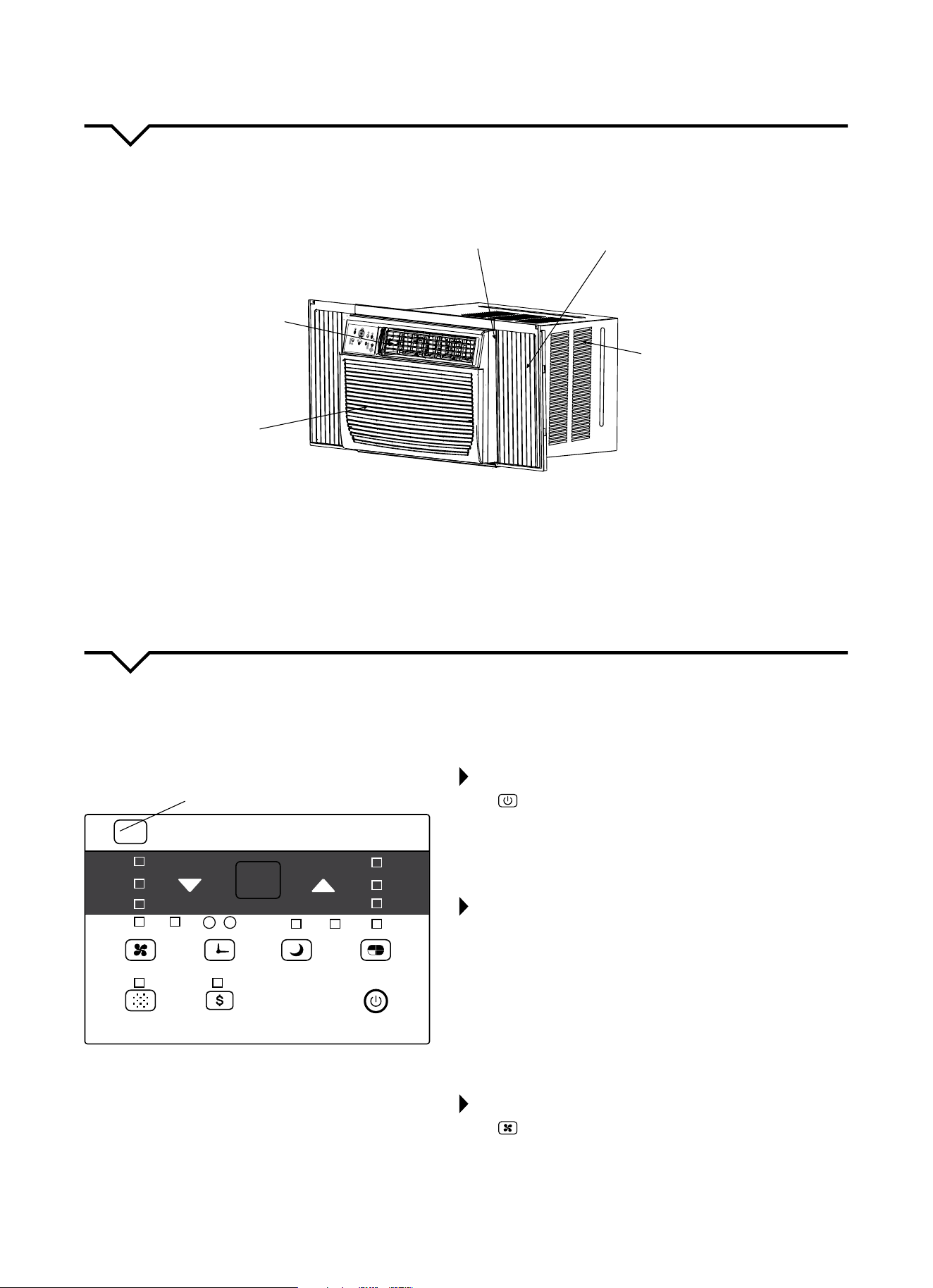
Thoroughlyfamiliarizeyourselfwiththecontrolpanel,shownbelow,andallofitsfunctions.Afterwards,followthesymbol
forthefunctionsyoudesireBEFOREoperatingtheunit.Thisunitcanbecontrolledbytheunitcontrolortheremote
control.
Remote Signal
Receptor
TO TURN UNIT ON OR OFF:
Press ON/OFFbuttontoturntheunitonoro.
NOTE: The unit will automatically initiate the Energy Saver
functionunderCOOL,DRYandAUTO(onlyAUTO-COOLING
andAUTO-FANmodes).
TO CHANGE TEMPERATURE SETTING:
Press
/
UP/DOWNbuttontochangethe
temperature setting.
NOTE: Press or hold either UP (
)orDOWN(
) button
until the desired temperature is shown on the display. The
temperature will be automatically maintained anywhere
between 62°F (17°C) and 86°F (30°C). If you want the display
toreadtheactualroomtemperature,see“ToOperateonFan
Only”section.
TO ADJUST FAN SPEEDS:
Press to select the Fan Speed in four steps: Auto, Low,
Med or High. Each time the button is pressed, the fan speed
isshifted.InDRYmode,thefanspeedisautomaticallycon-
trolled at Low. For some models with heating capabilities, the
fanspeedcannotbeadjustedwhileinHEATmode.
UNIT CONTROL PANEL
Heat indicator on models with
heating capabilities only.
Auto
Low
Med
High
Auto
Cool
Dry
Fan
TEMP/TIMER
On O
Sleep
Timer
Mode
Check
Filter
Energy
Saver
Fan
Follow
Me
Heat
14
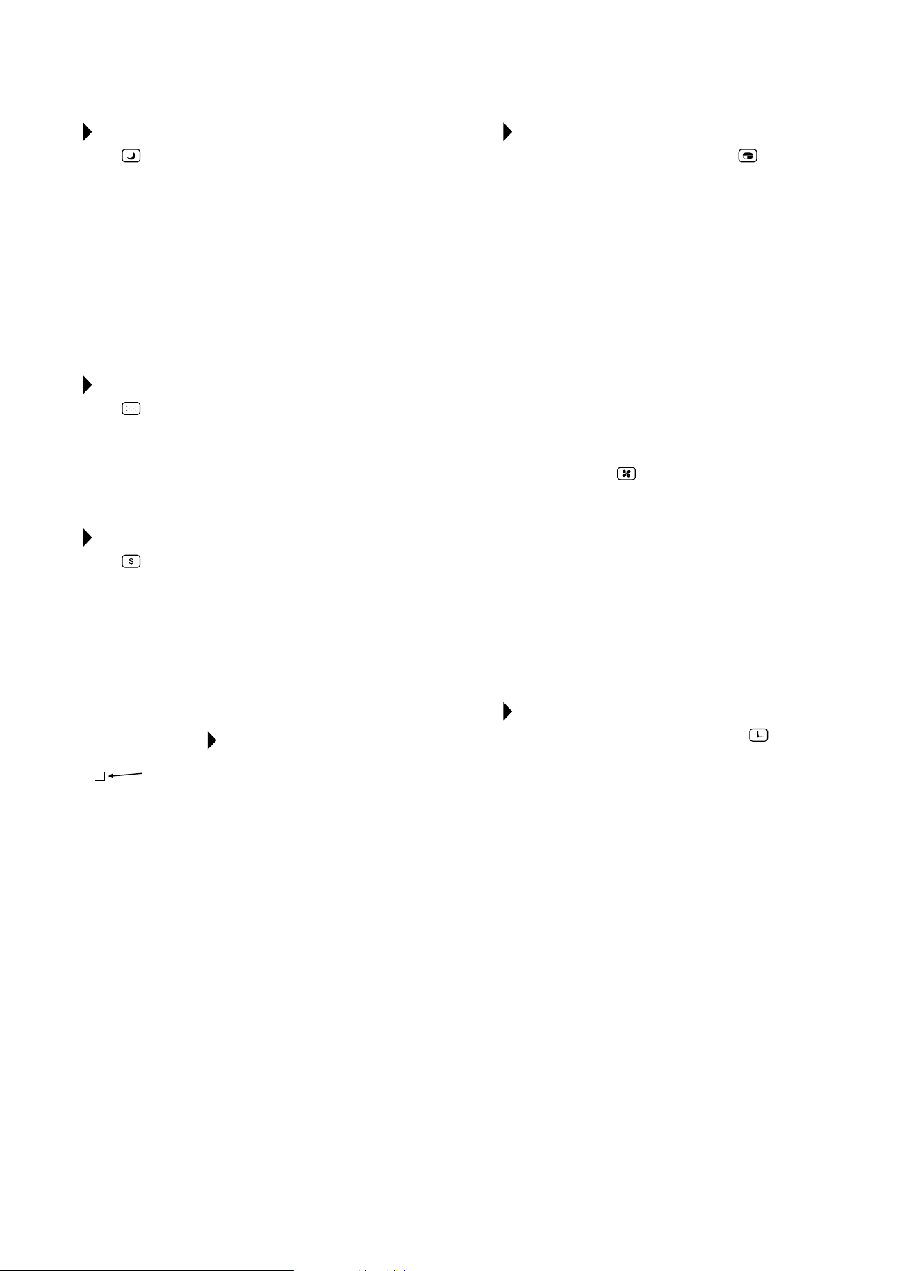
SLEEP FEATURE:
Press SLEEP button to initiate the SLEEP
mode. In this mode, the selected temperature will
increase by 2°F (1°C) 30 minutes after the mode is
selected. The temperature will then increase (cooling)
or decrease (units with heating only) by another
2°F (1°C) after an additional 30 minutes. This new
temperature will be maintained for 6 hours before it
returns to the originally selected temperature. This
ends the SLEEP mode and the unit will continue
to operate as originally programmed. The SLEEP
mode program can be canceled at any time during
operation by pressing the SLEEP button again.
CHECK FILTER FEATURE:
Press CHECK FILTER button to initiate this
feature. This feature is a reminder to clean the Air
Filterformoreecientoperation.TheLED(light)will
illuminate after 250 hours of operation. To reset after
cleaningthelter,presstheCHECK FILTER button
andthelightwillgoo.
ENERGY SAVER FEATURE:
Press ENERGYSAVER button to initiate this
function. This function is available on COOL, DRY
and AUTO (only AUTO-COOLINGand AUTO-FAN)
modes. In this mode, the fan will continue to run for 3
minutesafterthecompressorshutso.Thefanthen
cycles on for 2 minutes, at 10 minute intervals, until
the room temperature is above the set temperature,
atwhichtimethecompressorturnsbackonand
cooling starts.
FOLLOW ME FEATURE:
This feature can ONLY be activated
from the remote control. The
remote control serves as a remote
thermostat, allowing for precise
temperature control at its location.
To activate the Follow Me feature, point the remote
control toward the unit and press the FOLLOWME
button. The remote displays the actual temperature
at its location. The remote control will send this
signal to the air conditioner every 3 minutes until the
FOLLOWME button is pressed again. If the unit does
not receive the Follow Me signal during any 7 minute
interval, the unit will beep to indicate use of the
Follow Me feature has ended. The actual temperature
can be displayed on the unit by pressing the FAN
onlymode.WheninCOOLmode,theunitdisplay
indicates the set temperature.
TO SELECT THE OPERATING MODE:
To choose operating mode, press the MODE
button. Each time you press the button, a mode is
selectedinasequencethatgoesfromAUTO,COOL,
DRY, HEAT (for units with heating function) and FAN.
The indicator light will be illuminated and remain on
once the mode is selected. The unit will automatically
initiate the Energy Saver function under COOL, DRY, and
AUTO (only AUTO-COOLING and AUTO-FAN) modes.
TO OPERATE AUTO FEATURE:
When you set the air conditioner to AUTO mode, it
will automatically select cooling, or fan only operation
depending on what temperature you have selected
and the room temperature. The air conditioner will
automatically control room temperature around the
temperature you set. In this mode, the fan speed
cannot be adjusted. It starts automatically at a speed
according to the room temperature.
TO OPERATE FAN ONLY:
Use this function (
) only when cooling is not
desired, such as for room air circulation or to exhaust
stale air. (Remember to open the vent during this
function,butkeepitclosedduringcoolingfor
maximumcoolingeciency.)Youcanchooseany
fan speed you prefer. During this function, the display
will show the actual room temperature, not the set
temperature as in the cooling mode.
TO OPERATE ON DRY MODE:
In this mode, the air conditioner will reduce air
humidity. If the space is a closed or sealed area,
some degree of cooling will continue.
TIMER: AUTO START/STOP FEATURE:
● Whentheunitisonoro,rstpress TIMER
button.TheTIMERONindicatorlightilluminates.It
indicates the Auto Start program is initiated.
● WhenTIMERONisdisplayed,pressingtheTIMER
buttonagainilluminatestheTIMEROFFindicator,
indicating that the Auto Stop program is initiated.
● PressorholdtheUPorDOWNbuttontochange
the Auto time by 0.5 hour increments, up to 10
hours, then by 1 hour increments, up to 24 hours.
The control will count down the time remaining
until start.
● Theselectedtimewillregisterin5secondsand
thesystemwillautomaticallyrevertbackto
displaying the previous temperature setting or the
room temperature (depending on whether the unit
ispoweredonoroandthemodeitisin).
● TurningtheunitONorOFFatanytimeor
adjustingthetimersettingto0.0willcancelthe
AutoStart/Stopprogram.
A NOTE ABOUT THE TIMER:
When you set the timer, the
unitwillonlygoononceandoonce.Ifyouwantthe
airconditionertocycleonandobasedondesired
room temperature, you do not need to set the timer.
Instead, set your desired temperature and the unit will
cycleonandobasedonthattemperaturesetting.
Light
Flashing
Follow
Me
15
DISPLAY:
Shows the set temperature in °F or °C and the Auto-
timer settings. While in FAN only mode, it shows the
room temperature.
ERROR CODES:
AS - Room Temperature Sensor Error - Unplug the
unitandplugitbackin.Iferrorrepeats,call
Consumer Services at 844-472-2473.
HS - Electric Heating Sensor Error - Unplug the
unitandplugitbackin.Iferrorrepeats,call
Consumer Services at 844-472-2473.
●- Evaporator Temperature Sensor Error - Unplug
theunitandplugitbackin.Iferrorrepeats,call
Consumer Services at 844-472-2473.
NOTE: If an error code occurs in FAN only mode, the
unitwilldisplay“LO”(looseconnection)or“HI”
(short circuit).
NOTE
:
Iftheunitbreaksounexpectedlyduetopowerbeing
cut, it automatically will restart with the previous
function setting when the power resumes.
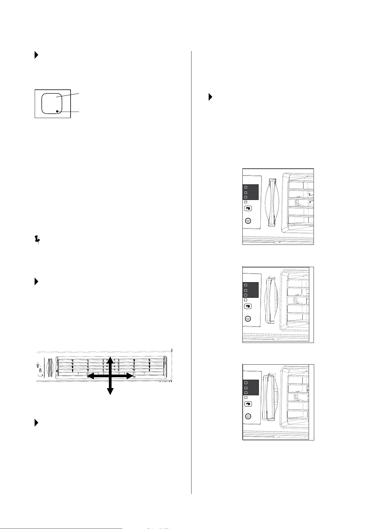
AIR DIRECTIONAL LOUVERS:
Usethe4-waydirectionallouverstodirecttheairow
up or down and left or right throughout the room as
needed.Pivothorizontallouversuntilthedesiredup/
down direction is obtained.
Move the levers from side to side until the desired
Left/Rightdirectionisobtained.
ADDITIONAL THINGS YOU
SHOULD KNOW:
● TheCoolcircuithasanautomatic3minute
time-delayedstartiftheunitisturnedoandon
quickly.Afterunitisturnedo,leavetheunito
for a minimum of 3 minutes before attempting to
turnbackon.Thispreventsoverheatingofthe
compressorandpossiblecircuitbreakertripping.
The fan will continue to run during this time.
● Thecontroliscapableofdisplayingtemperaturein
degrees Fahrenheit or degrees Celsius. To convert
from one to the other, press and hold the left and
right TEMP/TIMER buttons (
and
) at the
same time for 3 seconds.
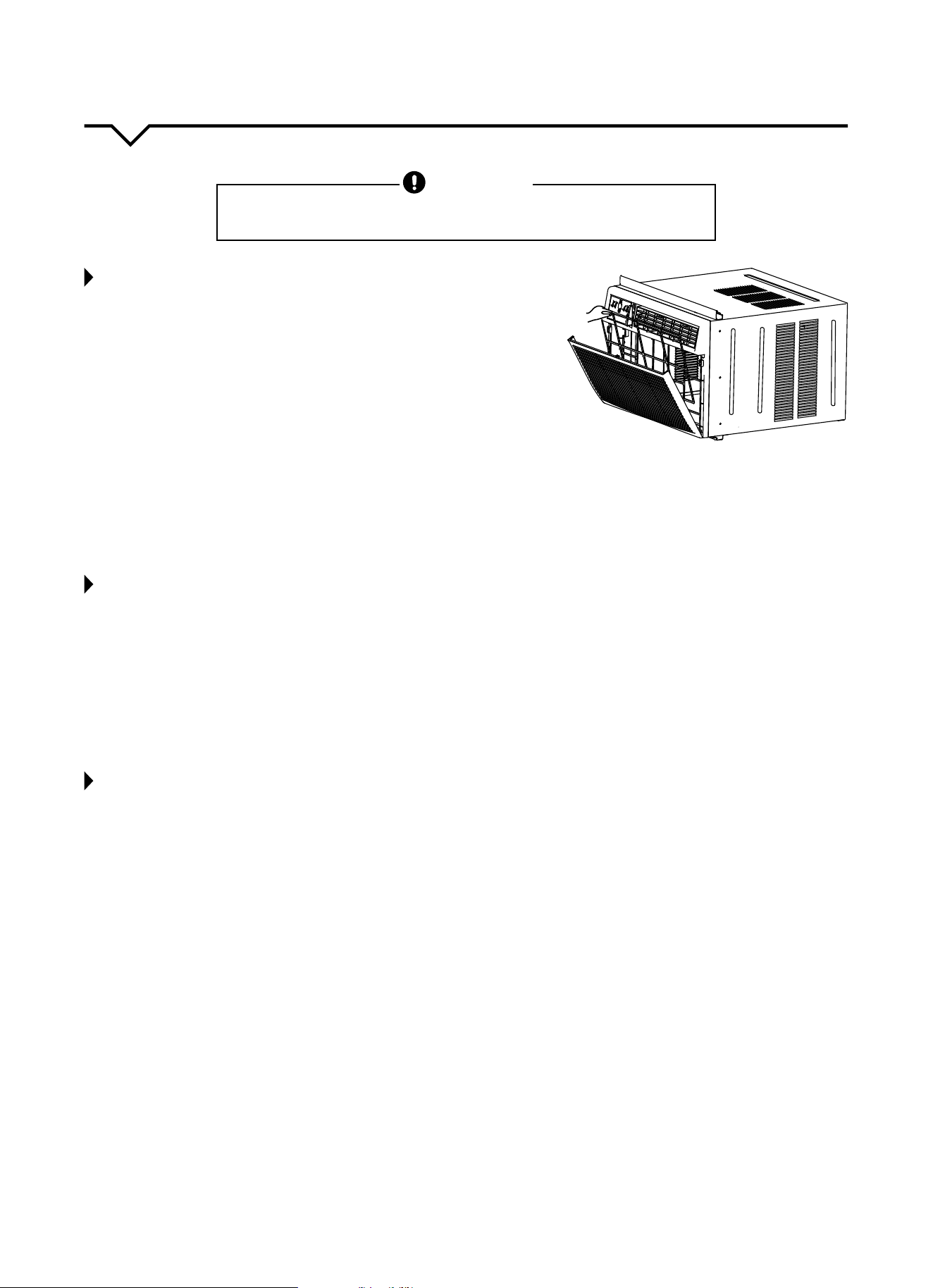
FRESH AIR VENT CONTROL
(on some models):
The Fresh Air Vent allows the air conditioner to:
1. Recirculate inside air (Vent Closed - Fig. A)
2. Drawfreshairintotheroom(VentOpen-FigB)
3. Exchange air from the room and draw fresh air into
theroom(VentandExhaustOpen-FigC)
Air Direction (4-way)
Air Directional Louvers
Display
Evaporator Temperature Sensor Error
Auto
Cool
Dry
Fan
Mode
Auto
Cool
Dry
Fan
Mode
Auto
Cool
Dry
Fan
Mode
Fig. A (VENT CLOSED)
Fig. B (VENT OPEN)
Fig. C (VENT AND EXHAUST OPEN)
16
CARE AND CLEANING
CAUTION
Cleanairconditioneroccasionallytokeepitlookingandoperatinglikenew.
Be sure to unplug the unit before cleaning to prevent shock or fire hazards.
AIR FILTER CLEANING
Theairltershouldbecleanedatleasteverytwoweeksoras
necessary.Trappedparticlesintheltercanbuildupandcausean
accumulation of frost on the cooling coils.
● PushtheventhandletotheVentClosedposition(whereapplicable).
● Openthefrontpanel.
● Graspthelterbythecenterandpullupandout.
● Washthelterusingliquiddishwashingdetergentandwarmwater.
Rinselterthoroughly.
● Gentlyshakeexcesswaterfromthelter.Besurethelteris
thoroughly dry before replacing.
● Asanalternativetowashingthelter,vacuumthelterclean.
NOTE: Never use hot water over 104°F (40°C) to clean the air filter.
Never attempt to operate the unit without the air filter.
CABINET CLEANING
● Besuretounplugtheairconditionertopreventshockorrehazard.
The cabinet and front may be dusted with an oil-free cloth or with
aclothdampenedinasolutionofwarmwaterandmildliquid
dishwashing detergent. Rinse thoroughly and wipe dry.
● Neveruseharshcleaners,waxorpolishonthecabinetfront.
● Besuretowringexcesswaterfromtheclothbeforewipingthe
controls. Excess water in or around the controls may cause damage
to the air conditioner.
● Pluginairconditionerafterunithasdriedcompletely.
WINTER STORAGE
If air conditioner will be stored during the winter, remove it carefully
from the window according to the installation instructions. Cover it with
plastic or return it to the original carton.
ALWAYS STORE UNIT IN AN UPRIGHT POSITION AND IN A COOL,
DRY LOCATION.

17
NOTE
Ahighlyrecommendedtroubleshootforanyissueingeneralconsistsofturningounitandunpluggingfor5
minutes. It is also recommended to try another wall outlet. For further assistance, contact Consumer Services at
844-472-2473.
TROUBLESHOOTING
BEFORE CALLING FOR SERVICE, PLEASE REVIEW THE CHART BELOW
ISSUE POSSIBLE CAUSES
AIR CONDITIONER NOT
COOLING ROOM, OR NOT BLOWING
COLD AIR
•Besureunitisnottoolargeortoosmallfortheareaoftheroom.
•Verifythatalldoors,windows,curtainsandanyotheropeningsareclosedo.
Verify nothing is obstructing the front grille of unit, such as curtains, etc.
•Allowenoughtimeforroomtocool,especiallyifoutsidetempisveryhigh.
•Checkthatthelterisnotdirtyandlouversareopenallthewayandblowinginthe
desired direction.
•CheckthatunitissettoCOOLmodeandthattemperatureisdownenough(but
not too low).
•Ifunitisnearaheatsource,suchasastove,etc.,thenrelocateunit.
•Ifaircomingfromunitiscooltothetouch,thenunitisworkingproperly;please
doublechecktherstthreebulletpointsabove.
•IfusingFollowMeremotefeature,moveremoteawayfromunit.
•Temperaturesensorbehindairltertouchingcoldcoil.Thesetwoelementsshould
not be touching. Carefully straighten tube away from coil.
•Unplugunitforatleast5minutes.FollowResetinstructionsonplug.
AIR CONDITIONER COOLING
BUT ROOM IS TOO WARM - ICE
FORMING ON COOLING COIL
BEHIND DECORATIVE FRONT
•Outdoortemperatureisbelow64ºF(18ºC).Todefrostthecoil,settoFAN
only mode.
•Airltermaybedirty.Cleanlter.RefertoCareandCleaningsection.Todefrost,
set to FAN only mode.
•Thermostatissettoocoldfornight-timecooling.Todefrostthecoil,settoFAN
only mode. Then, set temperature to a higher setting.
AIR CONDITIONER CYCLING ON
AND OFF TOO FREQUENTLY OR
NOT ENOUGH
•Besureunitisnottoolargeortoosmallfortheareaoftheroom.
•Removegrilleandmakesurethetemperaturesensorisnottooclosetothecoils.
These two elements should not be touching. Carefully straighten tube away
from coil.
•Makesurenothingisblockingthegrilleorsidevents.
•Makesurethereisnodirtordebrisinsidetheunitoronthelter.
UNIT WILL NOT TURN ON
•Resetcircuitbreaker.Makesuretherearenottoomanyitems(i.e.lamps,TV’s,
etc.)workingothesamebreaker.
•Checkplugconnection.
•Ifplugisoperatingonanon/oswitch,besurethattheswitchis‘on’.
•Trypluggingunitintoanotheroutlet.
•Unplugunitforatleast5minutes.FollowResetinstructionsonplug.
UNIT BLOWS FUSES OR POPS
CIRCUIT BREAKER
•Makesurethereareenoughavailableampsonthecircuitfortheairconditioner.
•Largeunitswhichrunona230vwillrequireadedicated20or30ampcircuit.
AIR CONDITIONER IS
MAKING NOISES
•Checktobesuretheunitisfreefromdebrissuchasleaves,sticks,etc.Verify
nothing is obstructing the unit.
•Checkthefanbladeforcracksorchips.
•Makesuretheunitisproperlyandsecurelymountedinsidethewindoworwall.
•Cleantheairlter.
WATER PUDDLES INSIDE UNIT OR IS
COMING INTO ROOM
•Adjusttheslopeoftheunitsothatitdrainsdownwardtowardtheexteriorofthe
home. (See Installation Instructions.)
•Makesurethatthereisnodebrisblockingthedrainageareaoftheunit.
WATER DRIPPING OUTSIDE
•Unitisremovingalargequantityofmoisturefromahumidroom.Thisisnormal
during excessively humid days.
REMOTE SENSING / FOLLOW ME
DEACTIVATING PREMATURELY
•Remotecontrolnotlocatedwithinrange.Placeremotecontrolwithin20ftand
180º radius of the front of the unit.
•Remotecontrolsignalobstructed.Removeobstruction.


The design and specifications are subject to change without prior notice for
product improvement. Consult with the sales agency or manufacturer for details.

Perfect Aire, LLC
5151 Belt Line Rd.
Suite 878
Dallas, TX 75254
Distributed by:
844-4PA-AIRE | 844-472-2473
www.perfectaire.us
WINDOW
AIR CONDITIONER
FOR MODEL:
4PAC15000
4PAC18000
4PAC25000
Before using your air conditioner, please
read this manual carefully and keep it for
future reference, along with your receipt.
Specification and performance data is subject to change without notice.
Printed in China
PA/User4PAC15000_4PAC18000_4PAC25000/10162017
USER MANUAL