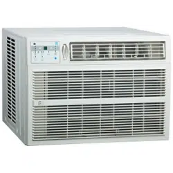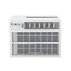
WINDOW AIR CONDITIONER
WITH WIRELESS CONTROLS
MODEL 1PAWFC14500
OWNER’S MANUAL
SAFETY PRECAUTIONS ...................................................................1
IMPORTANT SAFETY INSTRUCTIONS ...........................................9
INSTALLATION INSTRUCTIONS .....................................................10
WINDOW MOUNTING INSTALLATION INSTRUCTIONS .......12
THRU-THE-WALL INSTALLATION INSTRUCTIONS ..................17
MASONRY CONSTRUCTION ..........................................................18
NORMAL SOUNDS ...........................................................................19
AIR CONDITIONER FEATURES .......................................................19
CARE AND CLEANING ....................................................................22
TROUBLESHOOTING .......................................................................23
CONTENTS
This manual provides the information needed for proper use and mainte-
nance of this air conditioner. Basic preventative care can help extend the life
of this unit. The “Troubleshooting” section in this manual contains a chart
with solutions to the most common problems. Referring to this section may
save time and prevent the need for a service call in the event of a problem.
CAUTION
࡛ *VU[HJ[HUH\[OVYPaLKZLY]PJL[LJOUPJPHUMVYYLWHPYVYTHPU[LUHUJLVM[OPZ\UP[
࡛ 0MULJLZZHY`JVU[HJ[HUPUZ[HSSLYMVYPUZ[HSSH[PVUVM[OPZ\UP[
࡛ ;OLHPYJVUKP[PVULYPZUV[PU[LUKLKMVY\ZLI``V\UNJOPSKYLU^P[OV\[Z\WLY]PZPVU@V\UNJOPSKYLUZOV\SKILZ\WLY]PZLK
to ensure that they do not play with the air conditioner.
࡛ +PZHISLKWLYZVUZTH`YLX\PYLHZZPZ[HUJL^P[OZL[\W
࡛ 0M[OLWV^LYJVYKPZ[VILYLWSHJLKYLWSHJLTLU[^VYRZOV\SKILWLYMVYTLKI`H\[OVYPaLKWLYZVUULSVUS`
࡛ 0UZ[HSSH[PVUHUKYLWHPY^VYRT\Z[ILWLYMVYTLKPUHJJVYKHUJL^P[O[OLUH[PVUHS^PYPUNZ[HUKHYKZI`H\[OVYPaLK
personnel only.
࡛ +VUV[VWLYH[L`V\YHPYJVUKP[PVULYPUH^L[YVVTZ\JOHZHIH[OYVVTVYSH\UKY`YVVT
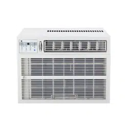
NOTE:(SS[OLPSS\Z[YH[PVUZPU[OPZTHU\HSHYLMVYL_WSHUH[PVUW\YWVZLZVUS`<UP[W\YJOHZLKTH`ILZSPNO[S`KPɈLYLU[
;OLKLZPNUHUKZWLJPÄJH[PVUZHYLZ\IQLJ[[VJOHUNL^P[OV\[WYPVYUV[PJLMVYWYVK\J[PTWYV]LTLU[*VU[HJ[*VUZ\TLY
Services as 844-4PA-AIRE (844-472-2473) for details.
1
WARNINGS
9
Plug in power cord properly. -HPS\YL[VKVZVTH`JH\ZLLSLJ[YPJZOVJRVYÄYLK\L[V
excess heat generation.
:
DO NOT operate or stop the unit by inserting or pull-
ing out the power plug directly from the wall.
+VPUNZVTH`JH\ZLLSLJ[YPJZOVJRVYÄYLK\L[V
heat generation.
:
DO NOT use a damaged power cord.
+VPUNZVTH`JH\ZLLSLJ[YPJZOVJRVYÄYL0M[OLWV^LY
cord is damaged, it must be replaced by the manufactur-
LYVYHUH\[OVYPaLKZLY]PJLJLU[LYVYHZPTPSHYS`X\HSPÄLK
WLYZVUPUVYKLY[VH]VPKHOHaHYK
:
DO NOT modify power cord length or share the
outlet with other appliances.
+VPUNZVTH`JH\ZLLSLJ[YPJZOVJRVYÄYLK\L[V
heat generation.
:
DO NOT operate with wet hands or in
damp environment.
+VPUNZVTH`JH\ZLLSLJ[YPJZOVJR
:
DO NOTKPYLJ[HPYÅV^KPYLJ[S`H[YVVTVJJ\WHU[Z
This could cause health issues.
9
(S^H`ZLUZ\YLLɈLJ[P]LNYV\UKPUN 0UJVYYLJ[NYV\UKPUNTH`JH\ZLLSLJ[YPJZOVJR
:
DO NOT allow water to run into electric parts.
+VPUNZVTH`JH\ZLMHPS\YLVMTHJOPULVYLSLJ[YPJZOVJR
9
(S^H`ZPUZ[HSSJPYJ\P[IYLHRLYHUKHKLKPJH[LK
power circuit.
0UJVYYLJ[PUZ[HSSH[PVUTH`JH\ZLÄYLHUKLSLJ[YPJZOVJR
9
Always unplug the unit if strange sounds, smell or
ZTVRLJVTLZMYVT[OL\UP[
-HPS\YL[VKVZVTH`JH\ZLÄYLHUKLSLJ[YPJZOVJR
:
DO NOT\ZL[OLZVJRL[PMP[PZSVVZLVYKHTHNLK
+VPUNZVTH`JH\ZLÄYLHUKLSLJ[YPJZOVJR
:
DO NOT open the unit during operation.
+VPUNZVTH`JH\ZLLSLJ[YPJZOVJR
:
DO NOT\ZLÄYLHYTZULHY\UP[
+VPUNZVTH`JH\ZLÄYL
:
DO NOT use the power cord close to
heating appliances.
+VPUNZVTH`JH\ZLÄYLHUKLSLJ[YPJZOVJR
:
DO NOT disassemble, modify, or drill holes into
the air conditioner.
+VPUNZVTH`JH\ZLMHPS\YLHUKLSLJ[YPJZOVJRHUK]VPK
the manufacturer’s warranty.
9
Ventilate room before operating air conditioner if
[OLYLPZHNHZSLHRMYVT
HUV[OLYHWWSPHUJLZ\JOHZ
a stove.
-HPS\YL[VKVZVTH`JH\ZLL_WSVZPVUÄYLHUKI\YUZ
:
DO NOT
\ZL[OLWV^LYJVYKULHYÅHTTHISLNHZVY
JVTI\Z[PISLZZ\JOHZNHZVSPULILUaLUL[OPUULYL[J
+VPUNZVTH`JH\ZLHUL_WSVZPVUVYÄYL
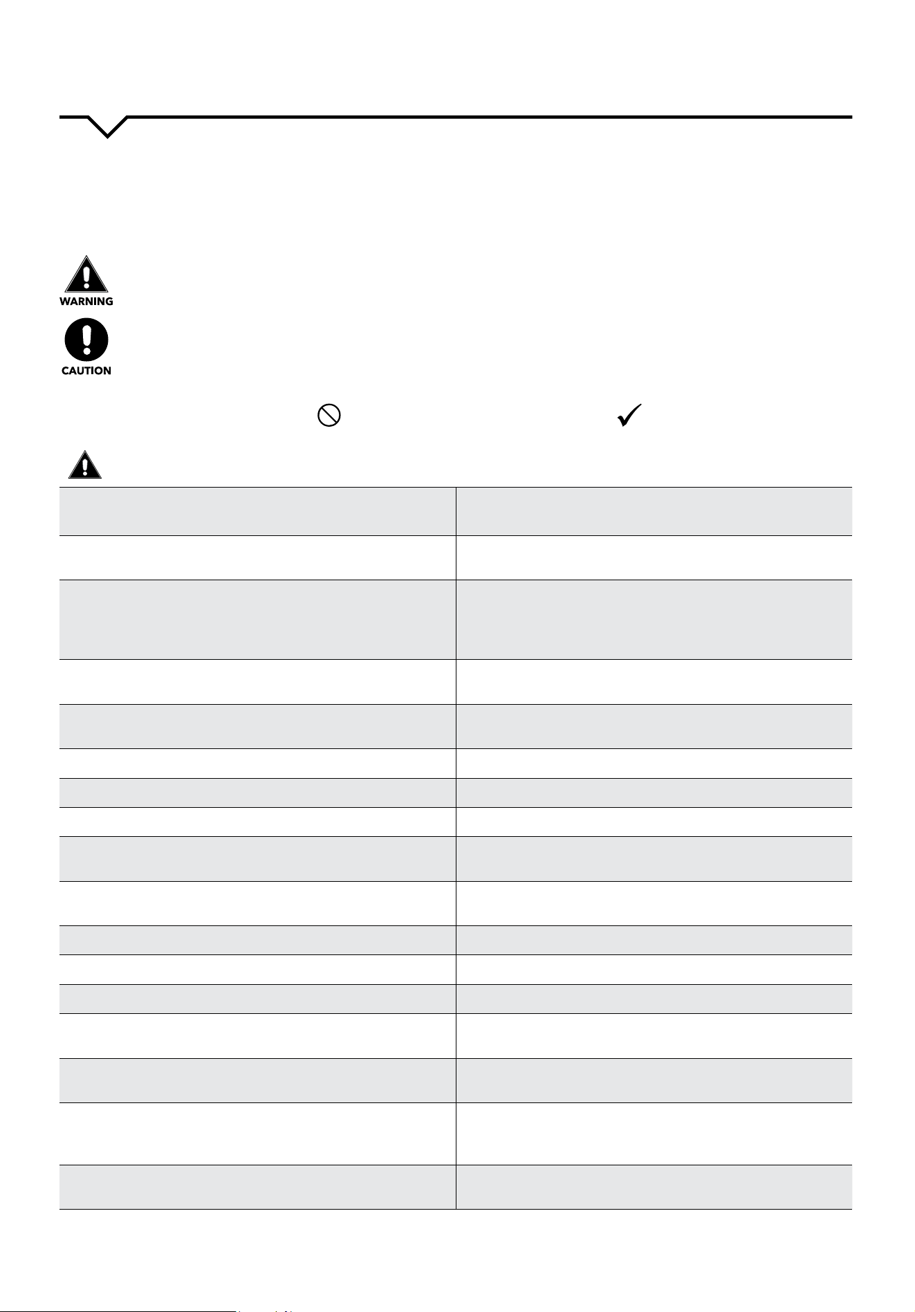
READ SAFETY PRECAUTIONS BEFORE INSTALLATION
;VWYL]LU[PUQ\Y`[V[OL\ZLYVYV[OLYWLVWSLHUKWYVWLY[`KHTHNL[OLMVSSV^PUNPUZ[Y\J[PVUZT\Z[ILMVSSV^LK
0UJVYYLJ[VWLYH[PVUK\L[VPNUVYPUNVMPUZ[Y\J[PVUZTH`JH\ZLOHYTVYKHTHNL;OLZLYPV\ZULZZPZJSHZZPÄLKI`[OL
following indications.
THIS SYMBOL INDICATES THAT IGNORING INSTRUCTIONS MAY CAUSE
DEATH OR SERIOUS INJURY.
NEVER DO THIS.OTHER SYMBOLS: ALWAYS DO THIS.
THIS SYMBOL INDICATES THAT IGNORING INSTRUCTIONS MAY CAUSE
MODERATE INJURY TO YOUR PERSON, OR DAMAGE TO YOUR UNIT OR
OTHER PROPERTY.
SAFETY PRECAUTIONS
1

2
CAUTIONS
:
>OLUYLTV]PUNHPYÄS[LYDO NOT touch metal parts of
the unit.
+VPUNZVTH`JH\ZLHUPUQ\Y`
:
DO NOT clean with water.
Water may enter the unit and degrade the insulation,
JH\ZPUNHULSLJ[YPJZOVJR
9
Ensure proper ventilation, especially in rooms with a
stove or other appliances.
Failure to do so may result in an oxygen shortage.
9
<UP[HUKJPYJ\P[IYLHRLYM\ZLT\Z[ILZ^P[JOLK6--
when cleaning.
*SLHUPUN\UP[^OLUWV^LYPZ65TH`JH\ZLÄYLHUK
LSLJ[YPJZOVJRHUKTH`JH\ZLHUPUQ\Y`
:
DO NOT put a pet or house plant where it will be ex-
WVZLK[VKPYLJ[HPYÅV^
;OPZJV\SKPUQ\YL[OLWL[VYWSHU[
9
Use ONLY as intended. This unit is NOT intended to preserve precision devic-
LZMVVKWL[ZWSHU[ZHUKHY[VIQLJ[Z0[TH`JH\ZL
KL[LYPVYH[PVUVMX\HSP[`L[J
9
Stop operation and close the window in severe
storms or hurricanes.
6WLYH[PVU^P[O^PUKV^ZVWLUTH`JH\ZLTVPZ[\YL[V
enter the room.
9
Hold the plug by the head of the power plug when
[HRPUNP[V\[
-HPS\YL[VKVZVTH`JH\ZLLSLJ[YPJZOVJR
and damage.
9
If unit will not be used for a long period of time,
unplug or turn OFF main power switch.
3LH]PUNWV^LYVUTH`JH\ZL\UP[MHPS\YLVYÄYL
:
Do not place obstacles around air-inlets or inside of
air-outlet.
6IZ[HJSLZTH`JH\ZLHWWSPHUJLMHPS\YLVYHJJPKLU[
9
7LYPVKPJHSS`JOLJRPUZ[HSSH[PVUIYHJRL[MVYKHTHNL Prolonged exposure to outdoor elements may cause
KHTHNL[VPUZ[HSSH[PVUIYHJRL[JH\ZPUN\UP[[VMHSS
9
(S^H`ZPUZLY[ÄS[LYZZLJ\YLS`*SLHUÄS[LYZAT LEAST
VUJLL]LY`[^V^LLRZ
6WLYH[PVU^P[OV\[ZLJ\YLS`PUZ[HSSLKÄS[LYZTH`
JH\ZLMHPS\YL(KPY[`ÄS[LYJHUJH\ZL[OL\UP[[VUV[
Y\ULɉJPLU[S`
9
Use only a soft cloth to clean the unit. Cleaners or detergents may change the color or
scratch the surface of the unit.
9
<ZLJH\[PVU^OLU\UWHJRPUNHUKPUZ[HSSPUN :OHYWLKNLZJV\SKJH\ZLPUQ\Y`
:
NEVERKYPUR^H[LYKYHPULKMYVTHPYJVUKP[PVULY
Water from unit contains contaminants and could
cause illness.
:
DO NOTWSHJLOLH]`VIQLJ[ZVU[OLWV^LYJVYKHUK
always ensure that the cord is not compressed.
;OLYLPZKHUNLYVMÄYLVYLSLJ[YPJZOVJR
9
If water enters the unit’s electrical components, turn
[OL\UP[VɈH[[OLWV^LYV\[SL[HUKZ^P[JOVɈ[OLJPY-
J\P[IYLHRLY0ZVSH[LZ\WWS`I`[HRPUN[OLWV^LYWS\N
V\[HUKJVU[HJ[HX\HSPÄLKZLY]PJLK[LJOUPJPHU
;OLYLPZKHUNLYVMLSLJ[YPJZOVJR
2
WARNING (For using R290/R32 refrigerant only)
• Do not use means to accelerate the defrosting process or to clean, other than those recommended by the manufacturer.
• The appliance shall be stored in a room without continuously operating ignition sources
• (for example: open ames, an operating gas appliance) and ignition sources or (for example: an operating electric heater)
close to the appliance. The appliance shall be stored in a room without continuously operating ignition sources (for
example: open ames, an operating gas appliance or an operating electric heater).
• Do not pierce or burn.
• Be aware that the refrigerants may not contain an odor.
• Compliance with national gas regulations shall be observed.
• Keep ventilation openings clear of obstruction.
• The appliance shall be stored so as to prevent mechanical damage from occurring.
• A warning that the appliance shall be stored in a well-ventilated area where the room size corresponds to the room area
as specied for operation.
• Any person who is involved with working on or breaking into a refrigerant circuit should hold a current valid certicate
from an industry-accredited assessment authority, which authorizes their competence to handle refrigerants safely in
accordance with an industry recognized assessment specication.
• Servicing should only be performed as recommended by the equipment manufacturer. Maintenance and repair requiring
the assistance of other skilled personnel shall be carried out under the supervision of the person competent in the use of
ammable refrigerants.
• DO NOT modify the length of the power cord or use an extension cord to power the unit.
• DO NOT share a single outlet with other electrical appliances. Improper power supply can cause re or electrical shock.
• Please follow the instructions carefully to handle, install, clear, service the air conditioner to avoid any damage or hazard.
Flammable Refrigerant R32 is used within the air conditioner. When maintaining or disposing the air conditioner, the
refrigerant (R32 or R290) should be recovered properly and should not be discharged into the air directly.
• DO NOT have any open re or device-like switch which may generate a spark/arcing around the air conditioner to avoid
causing ignition of the ammable refrigerant used.
• Please follow the instructions carefully to store or maintain the air conditioner to prevent mechanical damage from
occurring.
• Flammable refrigerant - R32 is used in air conditioner. Please follow the instructions carefully to avoid any hazard.
CAUTION: Risk of re/
ammable materials
(Required for R32/R290
units only
IMPORTANT NOTE: Read this manual
carefully before installing or operating your
new air conditioning unit. Make sure to save
this manual for future reference.
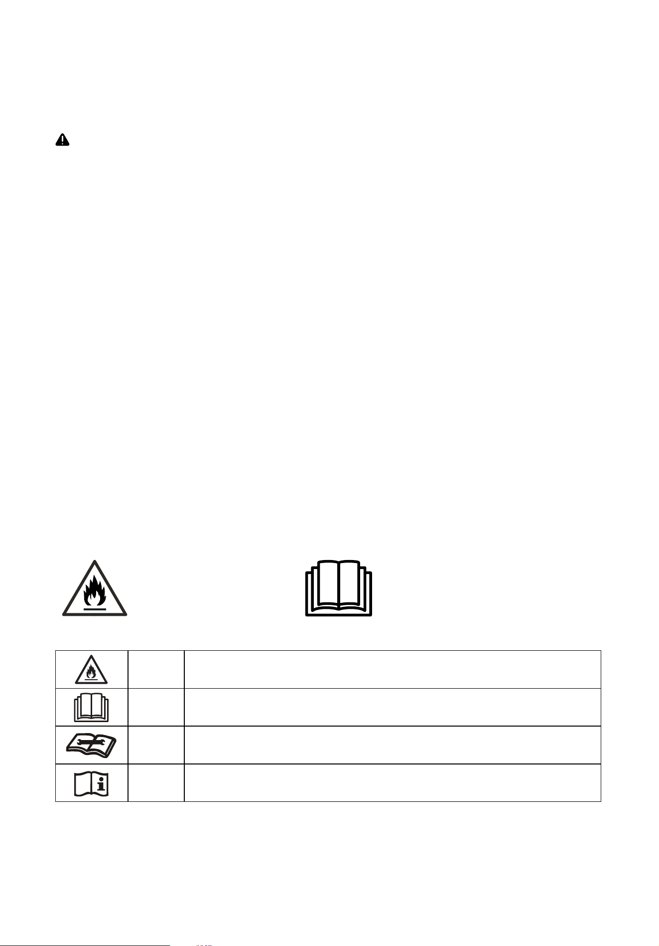
Explanation of symbols displayed on the unit (For units with R32/R290 Refrigerant only)
WARNING
This symbol shows that this appliance used a ammable refrigerant. If the refrigerant
is leaked and exposed to an external ignition source, there is a risk of re.
CAUTION
This symbol shows that the operation manual should be read carefully.
CAUTION
This symbol shows that a service professional should be handling this equipment
with reference to the installation manual.
CAUTION
This symbol shows that information is available such as the operation manual
installation manual.
3

WARNING
Transport of equipment containing ammable refrigerants
• See transport regulations.
Marking of equipment using signs
• See local regulations.
Disposal of equipment using ammable refrigerants
• See national regulations.
Storage of equipment/appliances
• The storage of equipment should be in accordance with the manufacturer’s instructions.
Storage of packed (unsold) equipment
• Storage package protection should be constructed such that mechanical damage to the equipment inside the
package will not cause a leak of the refrigerant charge.
• The maximum number of pieces of equipment permitted to be stored together will be determined by local regulations.
Information on servicing
1. Checking the area
• Prior to beginning work on systems containing ammable refrigerants, safety checks are necessary to
ensure that the risk of ignition is minimized. For repair to the refrigerating system, the following precautions
shall be complied with prior to conducting work on the system.
2. Work procedure
• Work shall be undertaken under a controlled procedure so as to minimize the risk of a ammable gas or
vapor being present while the work is being performed.
3. General work area
• All maintenance sta and others working in the local area shall be instructed on the nature of work being
carried out. Work in conned spaces shall be avoided. The area around the workspace shall be sectioned
o. Ensure that the conditions within the area have been made safe by control of ammable material.
4. Checking for presence of refrigerant
• The area should be checked with an appropriate refrigerant detector prior to and during work, to ensure the
technician is aware of potentially ammable atmospheres. Ensure that the leak detection equipment being
used is suitable for use with ammable refrigerants, i.e. non-sparking, adequately sealed or intrinsically safe.
5. Presence of a re extinguisher
• If any hot work is to be conducted on the refrigeration equipment or any associated parts, appropriate re
extinguishing equipment shall be available to hand. Have a dry powder or CO
2
re extinguisher adjacent to
the charging area.
6. No ignition sources
• No person carrying out work in relation to a refrigeration system which involves exposing any pipe work
that contains or has contained ammable refrigerant shall use any sources of ignition in such a manner that
it may lead to the risk of re or explosion. All possible ignition sources, including cigarette smoking, should
be kept suciently far away from the site of installation, repairing, removing and disposal, during which
ammable refrigerant can possibly be released to the surrounding space. Prior to work taking place, the
area around the equipment is to be surveyed to make sure that there are no ammable hazards or ignition
risks. No Smoking signs shall be displayed.
7. Ventilated area
• Ensure that the area is in the open or that it is adequately ventilated before breaking into the system or
conducting any hot work. A degree of ventilation shall continue during the period that the work is carried
out. The ventilation should safely disperse any released refrigerant and preferably expel it externally into
the atmosphere.
(For using R290/R32 refrigerant only)
4

WARNING
8. Checks to the refrigeration equipment
• Where electrical components are being changed, they shall be t for the purpose and to the correct
specication. At all times the manufacturer’s maintenance and service guidelines shall be followed. If in
doubt consult the manufacturer’s technical department for assistance.
• The following checks shall be applied to installations using ammable refrigerants:
• The charge size is in accordance with the room size within which the refrigerant containing parts are
installed.
• The ventilation machinery and outlets are operating adequately and are not obstructed.
• If an indirect refrigerating circuit is being used, the secondary circuit shall be checked for the
presence of refrigerant.
• Marking to the equipment continues to be visible and legible. Markings and signs that are illegible
should be corrected.
• Refrigeration pipe or components are installed in a position where they are unlikely to be exposed to
any substance which may corrode refrigerant containing components, unless the components are
constructed of materials which are inherently resistant to being corroded or are suitably protected
against being so corroded.
9. Checks to electrical devices
• Repair and maintenance to electrical components should include initial safety checks and component
inspection procedures. If a fault exists that could compromise safety, then no electrical supply shall be
connected to the circuit until it is satisfactorily dealt with. If the fault cannot be corrected immediately but
it is necessary to continue operation, an adequate temporary solution should be used. This should be
reported to the owner of the equipment, so all parties are advised.
• Initial safety checks should include:
• That capacitors are discharged: this shall be done in a safe manner to avoid possibility of sparking.
• That there no live electrical components and wiring are exposed while charging, recovering or purging
the system.
• That there is continuity of earth bonding.
10. Repairs to sealed components
• During repairs to sealed components, all electrical supplies shall be disconnected from the equipment
being worked upon prior to any removal of sealed covers, etc. If it is absolutely necessary to have an
electrical supply to equipment during servicing, then a permanently operating form of leak detection shall
be located at the most critical point to warn of a potentially hazardous situation.
• Particular attention shall be paid to the following to ensure that by working on electrical components, the
casing is not altered in such a way that the level of protection is aected. This shall include damage to
cables, excessive number of connections, terminals not made to original specication, damage to seals,
incorrect tting of glands, etc.
• Ensure that seals or sealing materials have not degraded such that they no longer serve the purpose of
preventing the ingress of ammable atmospheres. Replacement parts should be in accordance with the
manufacturer’s specications.
(For using R290/R32 refrigerant only)
NOTE: The use of silicon sealant may inhibit the eectiveness of some types of leak detection equipment.
Intrinsically safe components do not have to be isolated prior to working on them.
5

WARNING
11. Repair to intrinsically safe components
• Do not apply any permanent inductive or capacitance loads to the circuit without ensuring that this
will not exceed the permissible voltage and current permitted for the equipment in use. Intrinsically
safe components are the only types that can be worked on while live in the presence of a ammable
atmosphere. The test apparatus shall be at the correct rating.
• Replace components only with parts specied by the manufacturer. Other parts may result in the ignition of
refrigerant in the atmosphere from a leak.
12. Cabling
• Check that cabling will not be subject to wear, corrosion, excessive pressure, vibration, sharp edges or
any other adverse environmental eects. The check shall also take into account the eects of aging or
continual vibration from sources such as compressors or fans.
13. Detection of ammable refrigerants
• Under no circumstances, should potential sources of ignition be used in the searching for or detection of
refrigerant leaks. A halide torch (or any other detector using a naked ame) should not be used.
14. Leak detection methods
• The following leak detection methods are deemed acceptable for systems containing ammable refrigerants.
Electronic leak detectors shall be used to detect ammable refrigerants, but the sensitivity may not be
adequate, or may need re-calibration. (Detection equipment should be calibrated in a refrigerant-free area.)
Ensure that the detector is not a potential source of ignition and is suitable for the refrigerant used. Leak
detection equipment should be set at a percentage of the LFL of the refrigerant and shall be calibrated to
the refrigerant employed and the appropriate percentage of gas (25 % maximum) is conrmed.
• Leak detection uids are suitable for use with most refrigerants but the use of detergents containing
chlorine shall be avoided as the chlorine may react with the refrigerant and corrode the copper pipework.
• If a leak is suspected, all naked ames should be removed/ extinguished. If a leakage of refrigerant is
found which requires brazing, all of the refrigerant should be recovered from the system, or isolated (by
means of shut o valves) in a part of the system remote from the leak. Oxygen free nitrogen (OFN) should
then be purged through the system both before and during the brazing process.
15. Removal and evacuation
• When breaking into the refrigerant circuit to make repairs or for any other purpose conventional procedures
shall be used. However, it is important that best practice is followed since ammability is a consideration.
Opening of the refrigeration systems should not be done by brazing.
• The following procedure shall be adhered to:
• Remove refrigerant
• Purge the circuit with inert gas
• Evacuate
• Purge again with inert gas
• Open the circuit by cutting or brazing.
• The refrigerant charge should be recovered into the correct recovery cylinders. The system should
be ushed with OFN to render the unit safe. This process may need to be repeated several times.
Compressed air or oxygen shall not be used for this task.
• Flushing should be achieved by breaking the vacuum in the system with OFN and continuing to ll until
the working pressure is achieved, then venting to atmosphere, and nally pulling down to a vacuum. This
process shall be repeated until no refrigerant is within the system.
• When the nal OFN charge is used, the system shall be vented down to atmospheric pressure to enable work
to take place. This operation is absolutely vital if brazing operations on the pipework are to take place.
• Ensure that the outlet for the vacuum pump is not close to any ignition sources and there is ventilation
available.
(For using R290/R32 refrigerant only)
6

WARNING
16. Charging procedures
• In addition to conventional charging procedures, the following requirements should be followed. Ensure
that contamination of dierent refrigerants does not occur when using charging equipment. Hoses or lines
should be as short as possible to minimize the amount of refrigerant contained in them.
• Cylinders should be kept upright.
• Ensure that the refrigeration system is earthed prior to charging the system with refrigerant.
• Label the system when charging is complete (if not already).
• Extreme care should be taken not to overll the refrigeration system.
• Prior to recharging the system, it should be pressure tested with OFN. The system should be leak tested
on completion of charging but prior to commissioning. A follow up leak test should be carried out prior to
leaving the site.
17. Decommissioning
• Before carrying out this procedure, it is essential that the technician is completely familiar with the equipment
and all its detail. It is recommended good practice that all refrigerants are recovered safely. Prior to the task
being carried out, an oil and refrigerant sample should be taken in case analysis is required prior to re-use of
reclaimed refrigerant. It is essential that electrical power is available before the task is commenced.
• Become familiar with the equipment and its operation.
• Isolate the system electrically.
• Before attempting the procedure ensure that:
• When breaking into the refrigerant circuit to make repairs or for any other purpose,
conventional procedures should be used.
• Mechanical handling equipment is available, if required, for handling refrigerant cylinders.
• Personal protective equipment is available and being used correctly.
• The recovery process is supervised at all times by a competent person.
• Recovery equipment and cylinders conform to the appropriate standards.
• Pump down refrigerant system, if possible.
• If a vacuum is not possible, make a manifold so that refrigerant can be removed from various parts of
the system.
• Make sure that cylinder is situated on the scales before recovery takes place.
• Start the recovery machine and operate in accordance with manufacturer’s instructions.
Do not overll cylinders. (No more than 80 % volume liquid charge).
• Do not exceed the maximum working pressure of the cylinder, even temporarily.
• When the cylinders have been lled correctly and the process is completed, make sure that the
cylinders and the equipment are removed from the site promptly and all isolation valves on the
equipment are closed o.
• Recovered refrigerant should not be charged into another refrigeration system unless it has been
cleaned and checked.
18. Labelling
• Equipment should be labelled stating that it has been de-commissioned and emptied of refrigerant. The
label should be dated and signed. Ensure that there are labels on the equipment stating the equipment
contains ammable refrigerant.
(For using R290/R32 refrigerant only)
7

WARNING
19. Recovery
• When removing refrigerant from a system, either for servicing or decommissioning, it is recommended
good practice that all refrigerants are removed safely.
• When transferring refrigerant into cylinders, ensure that only appropriate refrigerant recovery cylinders are
employed. Ensure that the correct number of cylinders for holding the total system charge is available.
All cylinders to be used are designated for the recovered refrigerant and labelled for that refrigerant (i.e.
special cylinders for the recovery of refrigerant). Cylinders shall be complete with pressure relief valve and
associated shut-o valves in good working order. Empty recovery cylinders are evacuated and, if possible,
cooled before recovery occurs.
• The recovery equipment shall be in good working order with a set of instructions concerning the equipment
that is at hand and shall be suitable for the recovery of ammable refrigerants. In addition, a set of
calibrated weighing scales shall be available and in good working order.
• Hoses shall be complete with leak-free disconnect couplings and in good condition. Before using the
recovery machine, check that it is in satisfactory working order, has been properly maintained and that
any associated electrical components are sealed to prevent ignition in the event of a refrigerant release.
Consult manufacturer if in doubt.
• The recovered refrigerant shall be returned to the refrigerant supplier in the correct recovery cylinder, and
the relevant Waste Transfer Note arranged. Do not mix refrigerants in recovery units and especially not in
cylinders. If compressors or compressor oils are to be removed, ensure that they have been evacuated to
an acceptable level to make certain that ammable refrigerant does not remain within the lubricant. The
evacuation process shall be carried out prior to returning the compressor to the suppliers. Only electric
heating to the compressor body should be employed to accelerate this process. When oil is drained from a
system, it should be carried out safely.
(For using R290/R32 refrigerant only)
8
3
IMPORTANT SAFETY INSTRUCTIONS
NOTE
:
The power supply cord with this air
conditioner contains a current detection
KL]PJLKLZPNULK[VYLK\JL[OLYPZR
VMÄYL7SLHZLYLMLY[V[OLZLJ[PVU
¸6WLYH[PVUVM*\YYLU[+L]PJL¹ILSV^
for details. In the event that the power
supply cord is damaged, it cannot be
repaired. It must be replaced by an
H\[OVYPaLKYLWHPY[LJOUPJPHU^P[OHJVYK
from the Product Manufacturer.
WARNING
(]VPKÄYLOHaHYKZVYLSLJ[YPJZOVJRDO
NOT use an extension cord or an adapter
plug. DO NOT remove any prong from the
power cord.
OPERATION OF
CURRENT DEVICE:
The power supply cord contains a
current device that senses damage
to the power cord. To test your power
supply cord, do the following:
1. Plug in the air conditioner.
2. The power supply cord will have
;>6I\[[VUZVU[OLWS\NOLHK7YLZZ
[OL;,:;I\[[VU@V\^PSSUV[PJLH
JSPJRHZ[OL9,:,;I\[[VUWVWZV\[
3. Press the RESET button. Again,
`V\^PSSUV[PJLHJSPJRHZ[OL
button engages.
4. The power supply cord is now
Z\WWS`PUNLSLJ[YPJP[`[V[OL\UP[6U
some products this is also indicated
by a light on the plug head.)
WARNING
-69@6<9:(-,;@!+VUV[Z[VYLVY\ZLNHZVSPULVYV[OLYÅHTTHISL
]HWVYZHUKSPX\PKZPU[OL]PJPUP[`VM[OPZVYHU`V[OLYHWWSPHUJLZ
WARNING - PREVENT ACCIDENTS
;VYLK\JL[OLYPZRVMÄYLLSLJ[YPJHSZOVJRVYPUQ\Y`[VWLYZVUZ^OLU\ZPUN
your air conditioner, follow basic precautions, including the following:
࡛ )LZ\YL[OLLSLJ[YPJHSZLY]PJLPZHKLX\H[LMVY[OLTVKLS`V\OH]L
chosen. This information can be found on the serial plate, which is
located on the side of the cabinet and behind the grille.
࡛ 0M[OLHPYJVUKP[PVULYPZ[VILPUZ[HSSLKPUH^PUKV^`V\^PSSWYVIHIS`
^HU[[VJSLHUIV[OZPKLZVM[OLNSHZZÄYZ[0M[OL^PUKV^PZH[YPWSL
[YHJR[`WL^P[OHZJYLLUWHULSPUJS\KLKYLTV]L[OLZJYLLUJVTWSL[LS`
before installation.
࡛ )LZ\YL[OLHPYJVUKP[PVULYOHZILLUZLJ\YLS`HUKJVYYLJ[S`PUZ[HSSLK
according to the installation instructions in this manual.
࡛
Save this manual for possible future use in removing or installing this unit.
࡛ >OLUOHUKSPUN[OLHPYJVUKP[PVULYILJHYLM\S[VH]VPKJ\[ZMYVTZOHYW
TL[HSÄUZVUMYVU[HUKYLHYJVPSZ
WARNING - ELECTRICAL INFORMATION
The complete electrical rating of your new room air conditioner is
Z[H[LKVU[OLZLYPHSWSH[L9LMLY[V[OLYH[PUN^OLUJOLJRPUN[OL
LSLJ[YPJHSYLX\PYLTLU[Z
࡛ )LZ\YL[OLHPYJVUKP[PVULYPZWYVWLYS`NYV\UKLK;V TPUPTPaLZOVJR
HUKÄYLOHaHYKZWYVWLYNYV\UKPUNPZPTWVY[HU[;OLWV^LYJVYKPZ
LX\PWWLK^P[OH[OYLLWYVUNNYV\UKPUNWS\NMVYWYV[LJ[PVUHNHPUZ[
ZOVJROHaHYKZ
࡛ @V\YHPYJVUKP[PVULYT\Z[IL\ZLKPUHWYVWLYS`NYV\UKLK^HSS
YLJLW[HJSL0M[OL^HSSYLJLW[HJSL`V\PU[LUK[V\ZLPZUV[HKLX\H[LS`
NYV\UKLKVYWYV[LJ[LKI`H[PTLKLSH`M\ZLVYJPYJ\P[IYLHRLYOH]LH
X\HSPÄLKLSLJ[YPJPHUPUZ[HSS[OLWYVWLYYLJLW[HJSL
࡛ ,UZ\YL[OLYLJLW[HJSLPZHJJLZZPISLHM[LY[OL\UP[PUZ[HSSH[PVU
࡛ +VUV[Y\UHPYJVUKP[PVULY^P[OV\[ZPKLWYV[LJ[P]LJV]LYPUWSHJL;OPZ
could result in mechanical damage within the air conditioner.
࡛ +VUV[\ZLHUL_[LUZPVUJVYKVYHUHKHW[LYWS\N
NOTE
:
+VUV[\ZL[OLWS\N[V[\YU[OL\UP[VUVYVɈ
࡛ (S^H`ZTHRLZ\YL[OL9,:,;I\[[VUPZW\ZOLKPUMVYJVYYLJ[VWLYH[PVU
࡛ ;OLWV^LYZ\WWS`T\Z[ILYLWSHJLKPMP[MHPSZYLZL[^OLULP[OLY[OL;,:;
button is pushed or it cannot be reset.
࡛ 0MWV^LYZ\WWS`JVYKPZKHTHNLKP[JHUUV[ILYLWHPYLK7SLHZLJHSS
Consumer Services at 844-472-2473 to assist with replacement.
NOTE: This air conditioner is designed to be operated under the
following conditions:
Cooling
6WLYH[PVU
Outdoor Temp:
¶ -¶*
¶-¶*MVYZWLJPHS[YVWPJHSTVKLSZ
Indoor Temp:
¶ -¶*
Performance may be reduced outside of these operating temperatures.
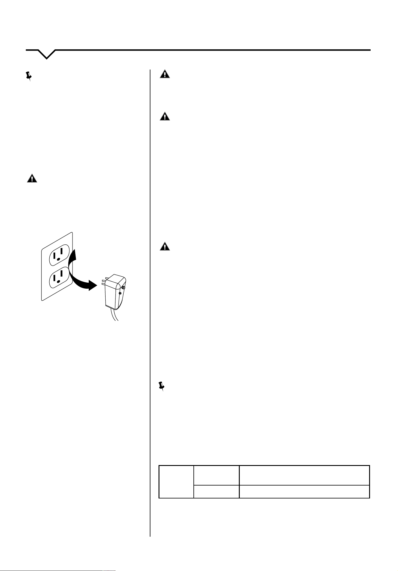
Grounding Type
Wall Receptacle
Do not, under any
circumstances, cut,
remove, or bypass the
ground prong.
Power supply cord
with 3-prong grounding
plug and current
detection device
9
4
BEFORE YOU BEGIN
Read these instructions completely and carefully.
IMPORTANT- Save these instructions.
IMPORTANT6IZLY]LHSSNV]LYUPUNJVKLZHUK
ordinances.
Note to Installer- Be sure to leave these instructions with
the Consumer.
Note to Consumer- Keep these instructions for future
reference.
Skill level0UZ[HSSH[PVUVM[OPZHWWSPHUJLYLX\PYLZIHZPJ
TLJOHUPJHSZRPSSZ
Completion time- Approximately 1 hour.
We recommend that two people install this product.
Proper installation is the responsibility of the installer.
Product failure due to improper installation is not
covered under the Warranty.
@V\4<:;\ZLHSSZ\WWSPLKWHY[ZHUK\ZLWYVWLY
installation procedures as described in these
instructions when installing this air conditioner.
CAUTION
Do not, under any circumstances, cut or remove the
third (ground) prong from the power cord.
Do not change the plug on the power cord of the air
conditioner.
Aluminum house wiring may present special problems-
JVUZ\S[HX\HSPÄLKLSLJ[YPJPHU
When handling unit, be careful to avoid cuts from sharp
TL[HSLKNLZHUKHS\TPU\TÄUZVUMYVU[HUKYLHYJVPSZ
REQUIRED TOOLS/HARDWARE
࡛ 7LUJPS
࡛ 3L]LS
࡛ ;HWLTLHZ\YL
࡛ :VJRL[^YLUJOLZ
࡛ 7OPSSPWZZJYL^KYP]LY
࡛ (KQ\Z[HISL^YLUJOVYWSPLYZ
࡛ 3HYNLÅH[ISHKLZJYL^KYP]LY
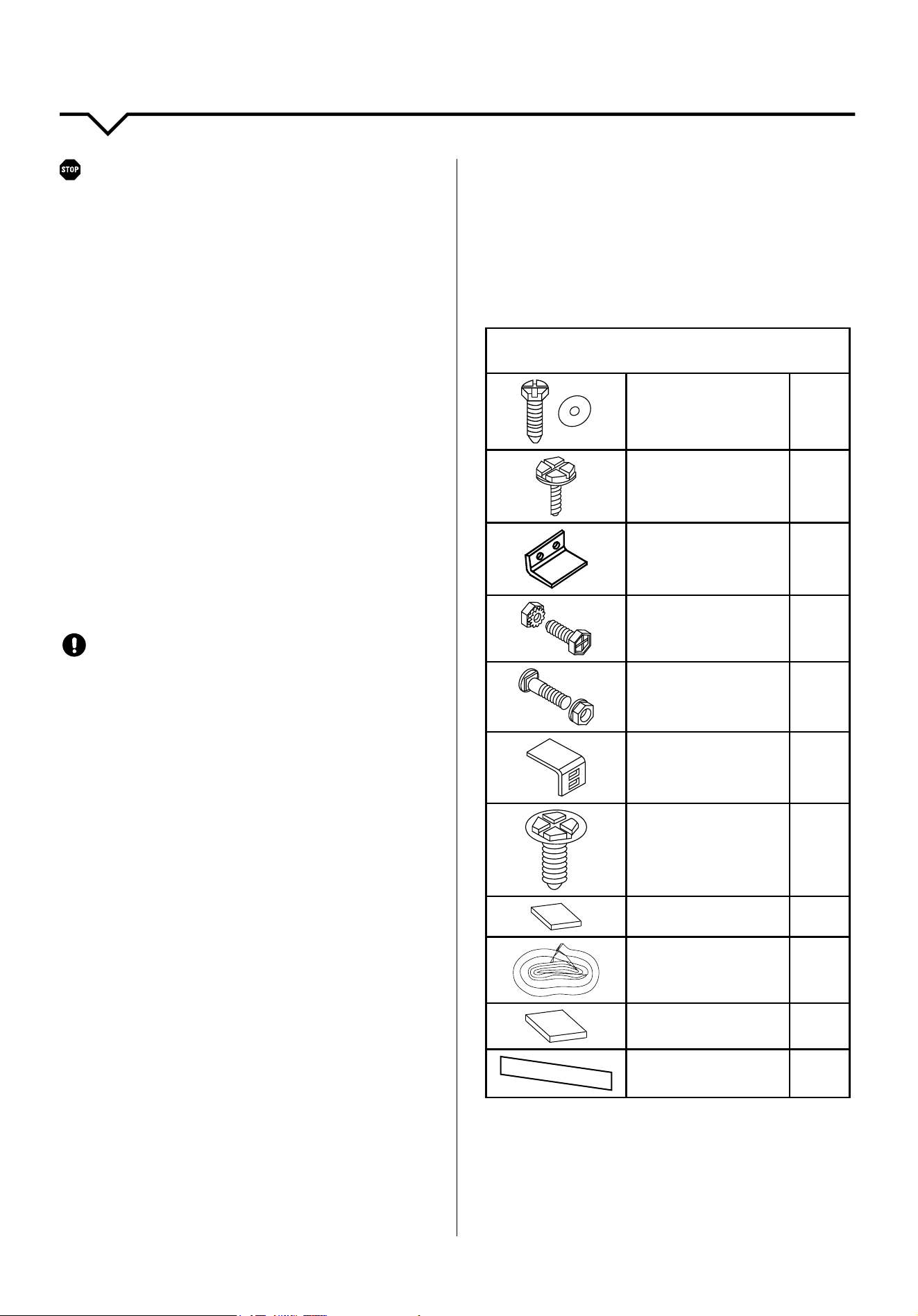
HARDWARE
(Included - Packed with the Unit)
PUJOSVJRPUN
ZJYL^HUKÅH[^HZOLY
for window panels
2 ea.
VYPUJO3VUN
Hex-head Screw
4
:HML[`3VJR
1
PUJO3VUN-SH[
Head Bolt and
3VJRU\[
4 ea.
PUJO3VUN:JYL^
HUK3VJRU\[
2 ea.
:PSS(UNSL)YHJRL[
2
3VUNOL_OLHKSVJRPUN
screw for tape angle,
ZPKLYL[HPSLYPUJO
long
10
Foam insert
2
Window sash seal
foam
1
Insulation Panels
2
>LH[OLYZ[YPWWPUN
__
5
INSTALLATION INSTRUCTIONS
10
5
Please read ALL instructions before installing. It is
recommended that two people install this product.
0MHUL^LSLJ[YPJHSV\[SL[PZYLX\PYLKOH]L[OLV\[SL[
PUZ[HSSLKI`HX\HSPÄLKLSLJ[YPJPHUILMVYLPUZ[HSSPUN[OL
air conditioning unit.
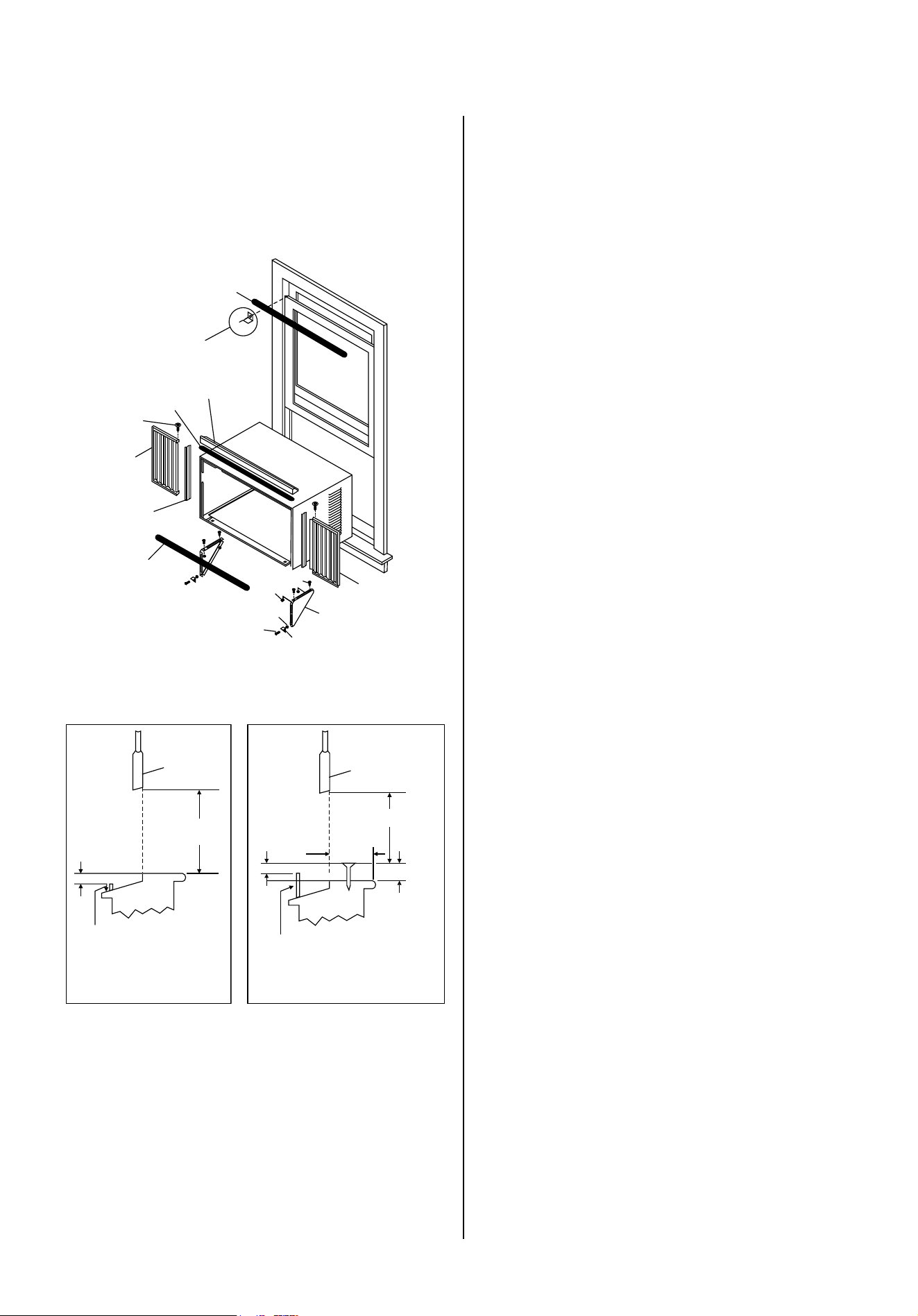
Window Sash Seal
Top Angle
Foam Gasket
Side Retainer
Locknut
Safety Lock and
3/4 (or 1/2)
Long Hex Head Screw
1/2 Long
Screw and
Locknuts
Washer Head
Locking Screw
Seal Bottom
Rail to Unit
Frame
Assembly
(Left)
Frame Assembly
(Right)
3/4 Long
Flat Head
Bolt
Sill Angle
Bracket
Window Support
Bracket
FIG. A
SASH
SASH
19 MIN.
19 MIN.
1/2 MIN.
1/2 MIN.
1/2 MIN.
Board
thickness
as required
along entire
stool. Fasten
with 2 Nails
or Screws.
Storm window
frame or other
obstruction
Storm window
frame or other
obstruction
FIG. B FIG. C
PRELIMINARY INSTRUCTIONS
Do the following before installing the unit. (See
illustrations on left.)
*OLJRKPTLUZPVUZVM`V\Y\UP[[VKL[LYTPULWYVWLY
window dimensions:
Unit Height: 17
5
8 or 18
5
8
Unit Width: 23
5
8 or 26
1
2
Min. Window Height: 18
1
2 or 19
1
2
Min. Window Width: 28 or 31
Max. Window Width: 40
1
2 or 42
1. CHECK WINDOW OPENING SIZE — The mounting parts
furnished with this air conditioner are made to install
in a wooden sill, double-hung window. The standard
WHY[ZHYLMVY^PUKV^KPTLUZPVUZSPZ[LKHIV]L6WLU
sash to a minimum of 19 in. (483 mm). See Fig. B .
2. CHECK CONDITION OF WINDOW — All wood parts of
^PUKV^4<:;ILPUNVVKZOHWLHUKHISL[VÄYTS`
OVSK[OLULLKLKZJYL^Z0MUV[THRLYLWHPYZILMVYL
installing unit.
3. CHECK YOUR STORM WINDOWS — If your storm
^PUKV^MYHTLKVLZUV[HSSV^[OLJSLHYHUJLYLX\PYLK
correct by adding a piece of wood, as shown in
Fig. C, or by removing storm window while room air
conditioner is being installed.
4. CHECK FOR ANYTHING THAT COULD BLOCK AIRFLOW —
*OLJRHYLHV\[ZPKLVM^PUKV^MVY[OPUNZZ\JOHZ
shrubs, trees, or awnings. Inside, be sure furniture,
KYHWLZVYISPUKZ^PSSUV[Z[VWWYVWLYHPYÅV^
5. CHECK THE AVAILABLE ELECTRICAL SERVICE — Power
supply MUST be the same as that shown on the
unit serial nameplate. Power cord is 48 inches long.
)LZ\YL`V\OH]LHUV\[SL[ULHY+656;\ZLHU
extension cord.
6. CAREFULLY UNPACK THE AIR CONDITIONER — Remove
HSSWHJRHNPUNTH[LYPHS*V]LY[OLÅVVYK\YPUN
installation to prevent damage. Two people should be
used to move and install unit.
11
6
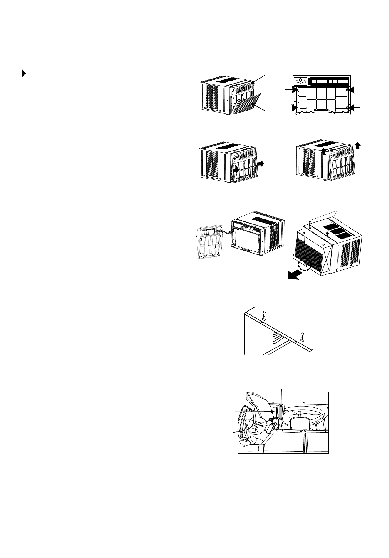
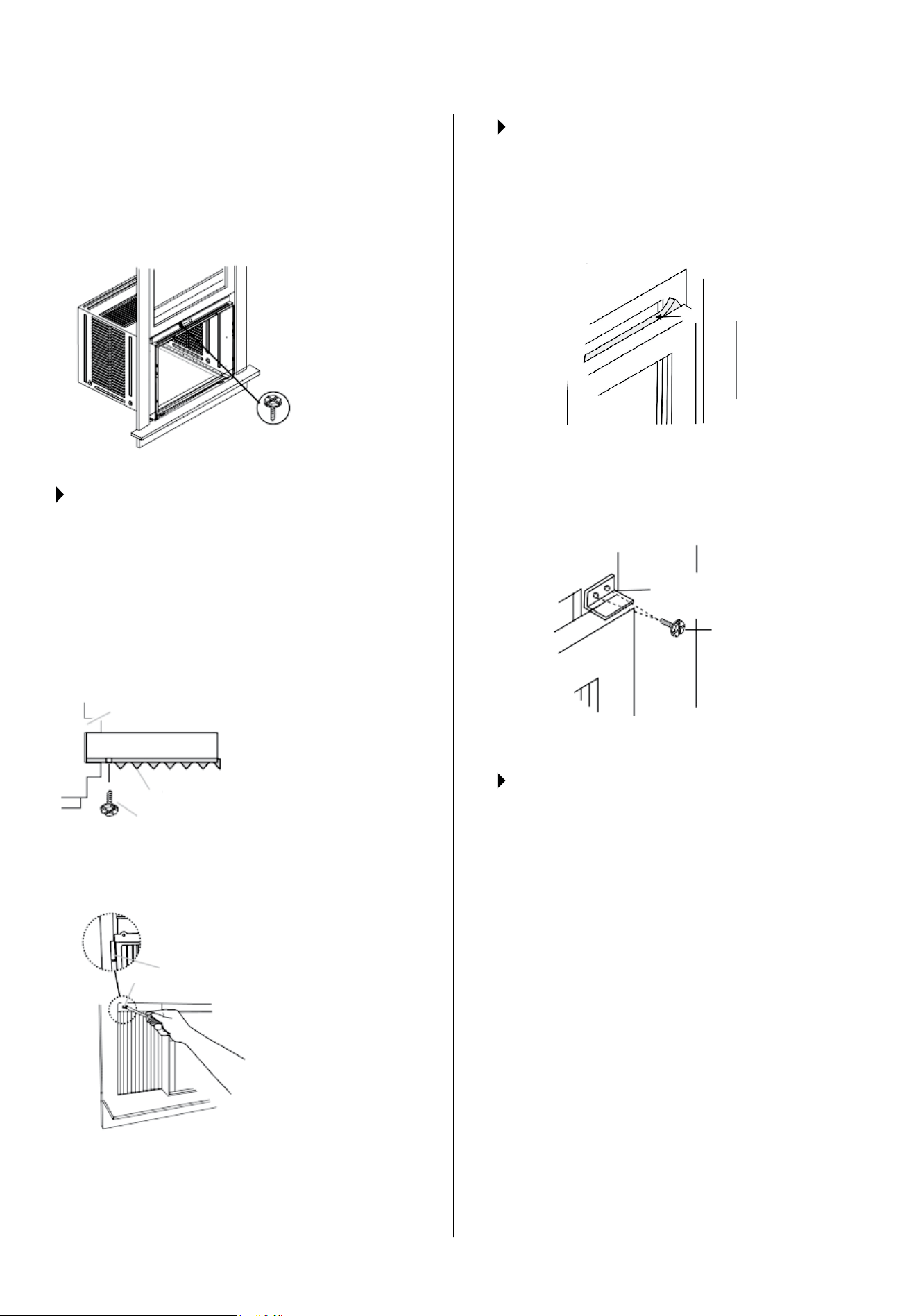
STEP 1:
REMOVE CHASSIS
7\SSKV^UMYVU[NYPSSLHUKYLTV]LÄS[LY
(See Fig. 1.)
2. Lift front grille upwards and place to one side.
3. Locate and remove the four front screws. These
screws will be needed to re-install the front panel
later. (See Fig. 2.)
4. Push metal cabinet side and pull on plastic frame
to release plastic tabs on each side of front panel.
(See Fig. 3.)
.LU[S`SPM[MYVU[WHULSVɈ\UP[
(See Fig. 3A.)
6. Disconnect the connector plug of the display
panel from the unit and place front panel to one
side. (See Fig. 4.)
7. Remove shipping screws from top of unit. (See
Fig. 5.)
8. Hold the cabinet while pulling on the base handle,
and carefully remove the unit.
9. Add two foam inserts to holes in top of cabinet
where shipping screws were removed from.
(See Fig. 6.)
@V\Y\UP[TH`JVTL^P[OPU[LYUHSWHJRHNPUN
ZOPWWPUNWHJRHNPUNWSHZ[PJ[PLZNYH`MVHT
WHKKPUNHZZOV^UPU-PN;OPZWHJRHNPUN
MUST be removed prior to installing the air
JVUKP[PVULYIHJRPU[V[OLJHIPUL[
DO NOT LIFT, PULL, OR REMOVE ANY EXPANDED
POLYSTYRENE (FOAM) FROM INSIDE OF THE AIR
CONDITIONER. IT IS NOT PACKING MATERIAL.
WINDOW MOUNTING INSTALLATION INSTRUCTIONS
FIG. 1
FIG. 4
FIG. 3
FIG. 2
FIG. 5
FIG. 6
FIG. 7
FIG. 3A
Shipping
Packaging
Shipping
Screws
Plastic Ties
Front Grille
Front Panel
Gray Foam
Padding
12
7
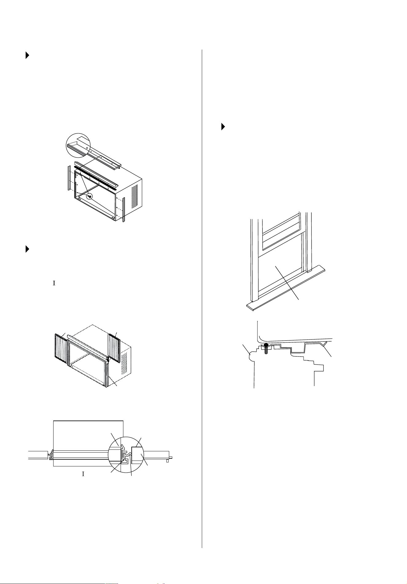
STEP 2:
INSTALL TOP ANGLE AND
SIDE BRACKET
1. ([[HJOMVHTNHZRL[[V[VWHUNSLHIV]LOVSLZHZ
shown in Fig. 6 on previous page.
2. Install top angle and side retainers to cabinet, as
shown in Fig. 8. (10 screws)
FIG. 8
5/16 l o n g
hex-head
STEP 3:
ASSEMBLE ACCORDION PANELS
7SHJLJHIPUL[VUÅVVYHILUJOVYH[HISL
2. Slide “
¹ZLJ[PVUVM^PUKV^ÄSSLYWHULSPU[VZPKL
retainer on the side of the cabinet. (See Fig. 9 and
Fig. 10.) Do this on both sides.
FIG. 9
FIG. 10
Accordion
Panel
Air Conditioner
Cabinet
Top
View
Plastic
Frame
Locking
Screw
Hole
Accordion
Panel
“
“ Section
Side Retainer
Plastic
Frame
0UZLY[[VWHUKIV[[VTSLNZVM^PUKV^ÄSSLYWHULS
frame into channel in the top angle and bottom rail.
Do this on both sides.
0UZLY[^HZOLYOLHKSVJRPUNZJYL^ZPU[V
OVSLZPU[VWSLNVMÄSSLYWHULSMYHTL:LLZ[LWVU
next page.) Do not totally tighten. Allow leg to slide
freely. Screws will be tightened after step 6.
STEP 4:
PLACE CABINET IN WINDOW
6WLU^PUKV^HUKTHYRJLU[LYVM^PUKV^ZPSS
(Fig. 11)
2. Place cabinet in window with bottom sill angle
ÄYTS`ZLH[LKV]LY^PUKV^ZPSSHZZOV^U)YPUN
window down temporarily behind top angle to hold
cabinet in place. (Fig. 12)
FIG. 12
FIG. 11
Sill
Angle
Sill
3. Shift cabinet left or right as needed to line up
JLU[LYVMJHIPUL[VUJLU[LYSPULTHYRLKVUZPSS
4. Fasten cabinet to window sill with 2 screws into
OVSLZ@V\TH`^PZO[VWYLKYPSSWPSV[OVSLZ
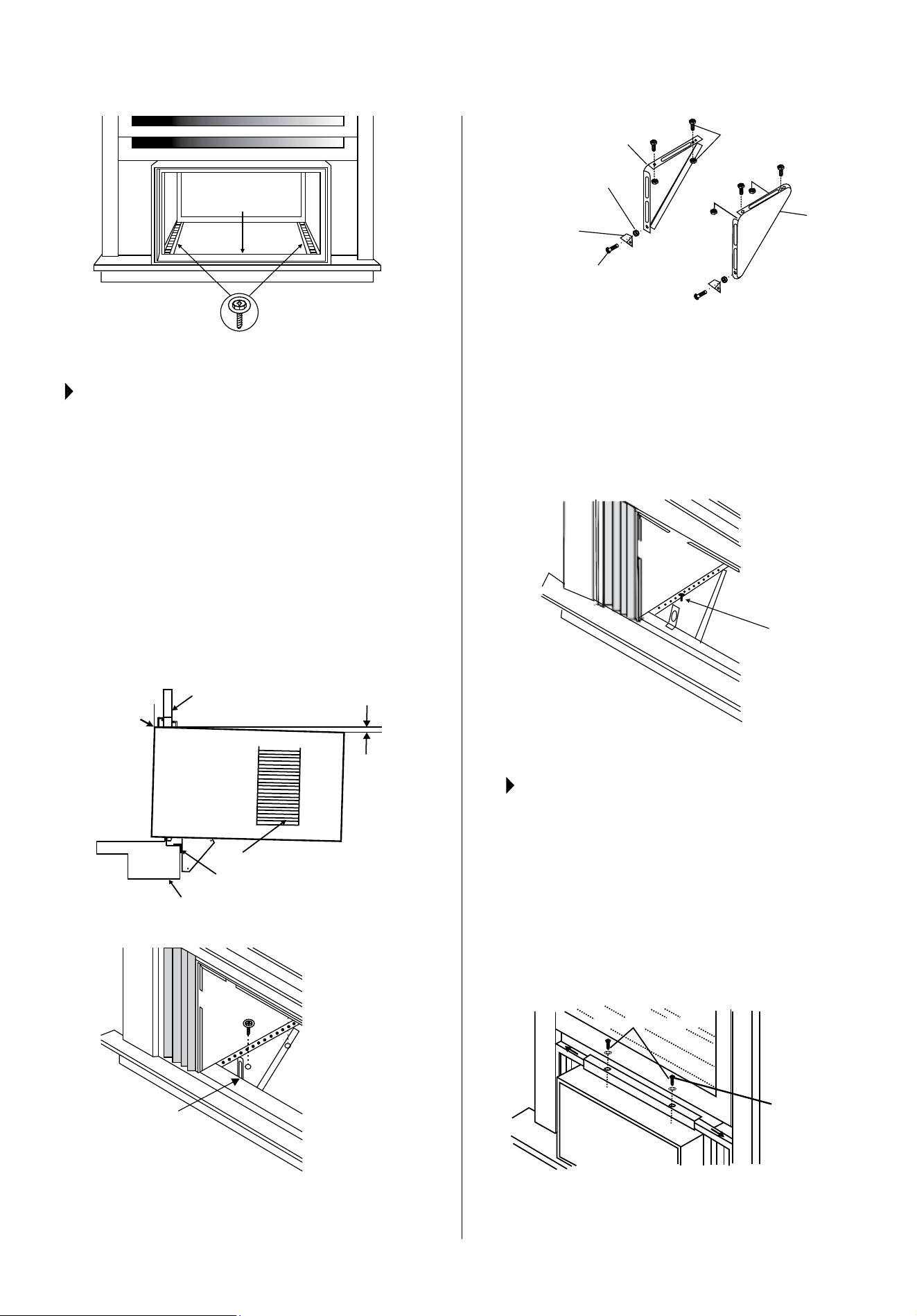
5. Add bottom rail seal over screw to window sill.
(See Fig. 13 on next page.)
13
8
FIG. 13
Bottom
Rail Seal
3/4 (or 1/2) long
Hex-head Screw
STEP 5:
INSTALL SUPPORT BRACKET
/VSKLHJOZ\WWVY[IYHJRL[Å\ZOHNHPUZ[V\[ZPKLVM
sill & tighten to bottom of cabinet, as shown in Fig.
(4HYRIYHJRL[ZH[[VWSL]LSVMZPSSHUKYLTV]L
(ZZLTISLZPSSHUNSLIYHJRL[[VZ\WWVY[IYHJRL[ZH[
[OLTHYRLKWVZP[PVU:LL-PN)/HUK[PNO[LU
but allow for any changes later.
NOTE:*OLJR[OH[HPYJVUKP[PVULYPZ[PS[LKIHJRHIV\[
1½w[Vɡw (tilted about 3º to 4º downward toward
the outside). If, after proper installation, condensation
KVLZUV[KYHPUMYVT[OLV]LYÅV^KYHPUOVSLK\YPUN
UVYTHS\ZLHKQ\Z[ZSVWL-PN
FIG. 14
FIG. 15A
Mark
About 1
1
2
to 1
5
8
Window Sash
Side Louvers
Sill Angle Bracket
Window Sill
Measure from the
cabinet edge.
5
FIG. 15B
Right
Left
Locknut
1/2 Log Screws
and Locknuts
2 Each Required for
Each Support Bracket
Sill Angle
Bracket
Flat Head
Bolt
0UZ[HSSZ\WWVY[IYHJRL[Z^P[OZPSSHUNSLIYHJRL[Z
attached) to correct hole in bottom of cabinet, as
shown in Fig. 16.
4. Securely tighten all 6 bolts.
1/2 Long
Screws and
Locknuts
FIG. 16
STEP 6:
EXTEND WINDOW
ACCORDION PANELS
1. Carefully raise window to expose accordion panel
SVJRPUNZJYL^Z3VVZLUZJYL^ZZVHJJVYKPVU
panels slide easily.
,_[LUKWHULSZ[VÄSS^PUKV^VWLUPUNJVTWSL[LS`
;PNO[LUSVJRPUNZJYL^ZVU[VW-PN(
3. Close window behind top angle.
Locking Screw
7/16 Locking
Screw and
Washer
FIG. 17A
14
9
([[HJO[OL[VWHUNSL[V^PUKV^MYHTL!<ZLH
drill bit to drill one hole through the hole in the
middle of top angle into the window frame, and
KYP]LVULVY/,?/,(+SVJRPUNZJYL^
through hole in the middle of top angle into the
window frame, as shown (Fig. 17B).
3/4 (or 1/2) long
hex head screw
FIG. 17B
STEP 7:
ATTACH ACCORDION PANELS TO
WINDOW FRAME
1. Extend the accordion panels out against the
window frame.
<ZLKYPSSIP[[VKYPSSHZ[HY[LYOVSL[OYV\NO[OL
OVSLPU[OL[VWSLNVMLHJO^PUKV^ÄSSLYWHULSHUK
into the window sash. (Fig. 18A and Fig. 18B.)
*VUULJ[^P[OVULVYSVUNOL_
head screw.
A. 3/4 (or 1/2)
long hex head
screw
B. Left-hand
Window Filler
Panel Top Leg
C. Window channel
A. 3/4 (or 1/2)
long hex head
screw
A
A
B
C
Window Sash
Weather Seals
FIG. 18A
FIG. 18B
STEP 8:
INSTALL WINDOW SASH SEAL AND
SAFETY LOCK
;YPTZHZOZLHS[VÄ[^PUKV^^PK[O0UZLY[PU[V
space between upper and lower sashes. (Fig 19A)
Window Sash Seal
FIG. 19A
([[HJOYPNO[HUNSLZHML[`SVJR-PN )
FIG. 19B
Safety Lock
3/4 (or 1/2)
long hex head
screw
STEP 9:
INSTALL CHASSIS INTO CABINET
AND INSTALL FRONT TO UNIT
1. Lift air conditioner and carefully slide into cabinet,
leaving 6 inches protruding.
+656;W\ZOVUJVU[YVSZVYÄUULKJVPSZ
)LZ\YLJOHZZPZPZÄYTS`ZLH[LK[V^HYKZYLHYVM
cabinet.
4. Installation of front is the reverse of removal
outlined in Step 1.
15
10
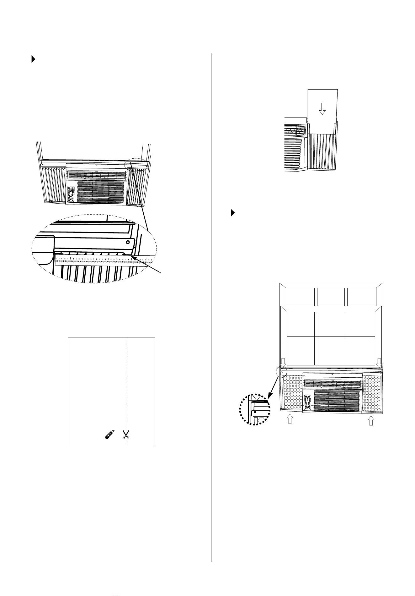
STEP 10:
INSTALL INSULATION PANELS
0UVYKLY[VTPUPTPaLHPYSLHRZHUKLUZ\YLVW[PTHS
insulation, it is necessary to install the included
insulation panels to the accordion panels. Follow the
4 steps in these instructions:
STEP 10.1: After the unit is installed in the window,
measure the inner width of one of the accordion
panels, as shown in Fig. 20.
1 2 3 4 5 6 7 8 9 10 11 12 13
14 15 16 17
1
2 3 4 5 6
STEP 10.2:4HYRHSPULVUVULVM[OLWYV]PKLK
insulation panels, matching the measured width in
Step 10.1; Cut the insulation panel along the line
(Fig. 21).
or
STEP 10.3::SPKL[OLPUZ\SH[PVUWHULS`V\Q\Z[J\[
into the accordion panel (curtain). The side of the
insulation panel with the pattern on it should face
indoors. (Fig. 22)
STEP 10.4: Repeat on other side with the second
insulation panel.
STEP 11:
INSTALL WEATHER STRIPPING
0UVYKLY[VTPUPTPaLHPYSLHRZIL[^LLU[OLYVVTHPY
conditioner and the window opening, install weather
stripping into any gaps as you see necessary by
trimming the weather stripping to the desired length,
WLLSPUNVɈ[OLWYV[LJ[P]LIHJRPUNHUKÄSSPUN[OLZL
gaps. (Fig. 23)
FIG. 20
FIG. 21
Measure
the inner
width of
one of the
accordion
panels.
FIG. 22
FIG. 23
16
11
THRU-THE-WALL INSTALLATION INSTRUCTIONS
STEP 1:
SELECT WALL LOCATION
The air conditioner has a slide-out chassis so that it can be
PUZ[HSSLK[OYV\NOHUV\[ZPKL^HSSHZZWLJPÄLKILSV^!
4H_>HSS;OPJRULZZ!VY
04769;(5;!:PKLSV\]LYZT\Z[UL]LYILISVJRLK
56;,!(SSWHY[ZULLKLKMVY;OY\;OL>HSS0UZ[HSSH[PVUHYL
provided except a wood frame, shims, and 10 wood screws
(#10-1 long minimum).
Select a wall surface that:
+VLZUV[Z\WWVY[THQVYZ[Y\J[\YHSSVHKZZ\JOHZ[OLMYHTL
construction at ends of windows, under truss-bearing
points, etc.
+VLZUV[OH]LWS\TIPUNVY^PYPUNPUZPKL
0ZULHYL_PZ[PUNLSLJ[YPJHSV\[SL[ZVY^OLYLHUV[OLYV\[SL[
can be installed.
-HJLZHUKPZUV[ISVJRLK[OLHYLH[VILJVVSLK
(SSV^Z\UISVJRLKHPYÅV^MYVTYLHYZPKLZHUKLUKV\[ZPKL
of installed air conditioner.
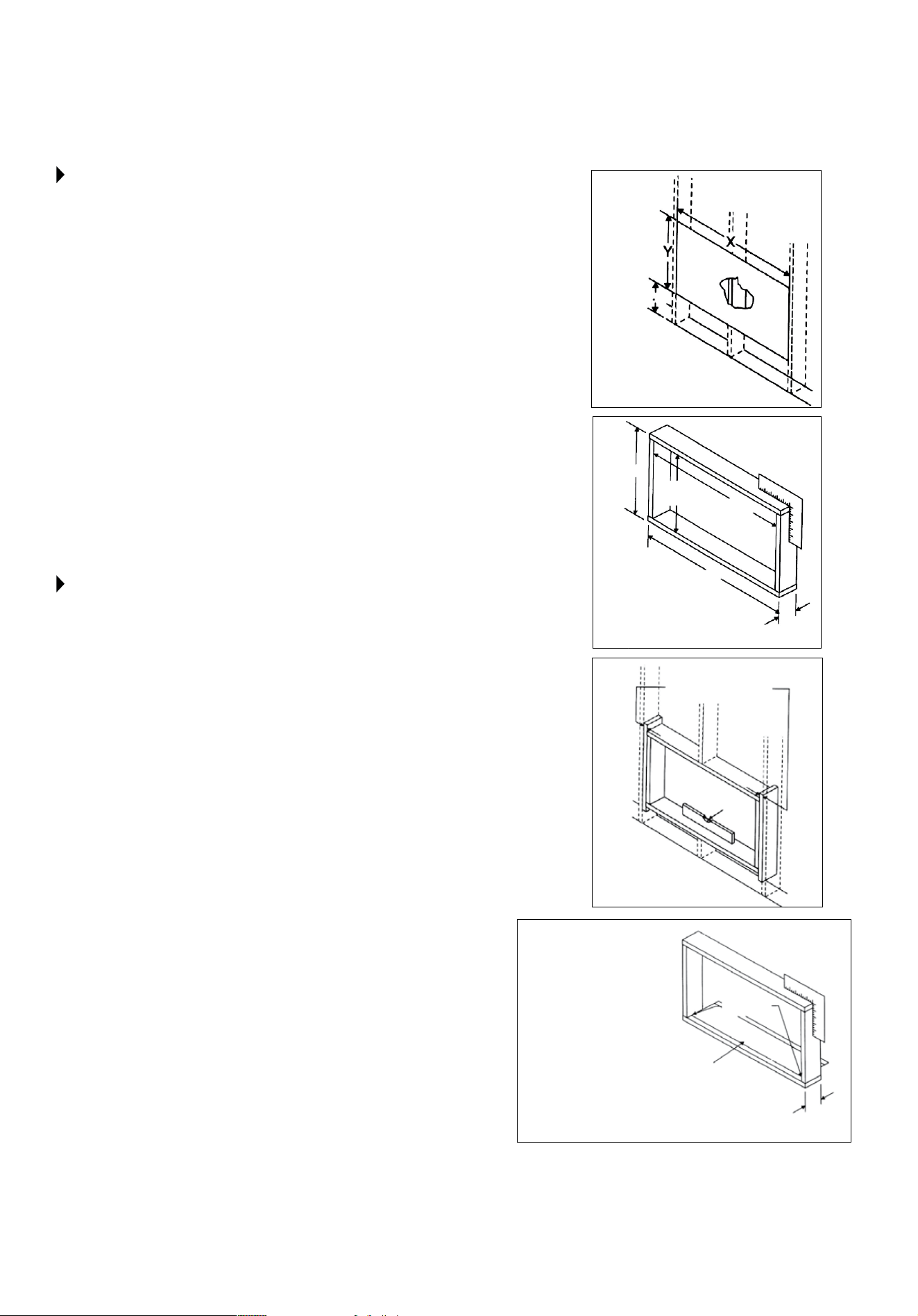
STEP 2:
PREPARE WALL
7YLWHYL^HSSPUMYHTLJVUZ[Y\J[PVUPUJS\KPUNIYPJRHUK
Z[\JJV]LULLY>VYRPUNMYVTPUZPKL[OLYVVTÄUK^HSS
stud nearest the center of area where air conditioner will be
PUZ[HSSLKI`ZV\UKPUN^HSSVYI`THNUL[PJHSS`ÄUKPUNUHPSZ
*\[VYRUVJRV\[HOVSLVULHJOZPKLVMJLU[LYZ[\K
3. Measure between inside edges of every other stud as
shown in Fig. 1.
56;,!*HYLM\SS`TLHZ\YLHUKJ\[HUVWLUPUN^P[O[OL
following dimensions, depending on your model. (See Fig. 1
and 2.)
>0+;/¸?¹$ PUZPKLTVKLS^PK[OWS\Z[^PJL[OL[OPJRULZZVM
framing material used.
/,0./;¸@¹$ PUZPKLTVKLSOLPNO[WS\Z[^PJL[OL[OPJRULZZVM
framing material used.
0UZPKL-YHTL/LPNO[ JTVYJT
0UZPKL-YHTL>PK[O! JTVYJT
4. Build wooden frame with the INSIDE dimensions of
your model listed above. (Be sure to measure twice for
accuracy.) Frame depth should be the same as wall
[OPJRULZZ-PSSPU[OLZWHJLMYVT[OLVWLUPUN[V[OLZ[\KZ
with wood spacers. (See Fig. 3.)
5HPSMYHTLZWHJLYZ^P[OMYVU[Å\ZO^P[OKY`^HSS
X
Y
FIG. 1
FIG. 2
FIG. 3
FIG. 4
Nail
Spacers to Studs
Caulk as
required
Aluminum
Flashing Over
Bottom of
Frame
NOTE:
If wall thickness is
8.5 or more, add
aluminum flashing
over bottom of frame
opening to assure no
water can enter area
between inner and
outer wall.
Level
Inside
Frame
Height
Inside
Frame
Width
Up to
8.5
Over
8.5
17
12
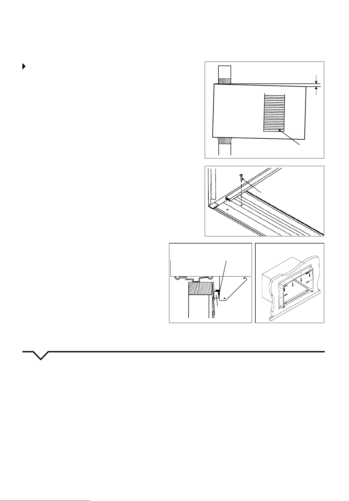
STEP 3:
PREPARE AND INSTALL CABINET
:SPKLJOHZZPZMYVTJHIPUL[9LMLYIHJR[V:[LWVM
Window Mounting section.
2. Place cabinet into opening with bottom rail resting
ÄYTS`VUIV[[VTIVHYKVM^VVKLUMYHTL
3. Position cabinet to achieve proper slope for water
removal. (See Fig. 5.)
4. Secure bottom rail to wooden frame with two large
^VVKZJYL^ZJTSVUN\ZPUN[OL[^VOVSLZPU
the bottom of the channel resting on frame. (See
Fig. 6.)
Refer to Step 5 of Window Mounting section for
HZZLTIS`VMZ\WWVY[IYHJRL[Z(^VVKLUZ[YPWUHPSLK[V
[OLV\[ZPKL^HSSZOV\SKIL\ZLKPUJVUQ\UJ[PVU^P[OZPSS
Z\WWVY[HUNSLIYHJRL[Z:LL-PN
5. Screw or nail cabinet wooden frame using shims, if
MYHTLPZV]LYZPaLK[VLSPTPUH[LKPZ[VY[PVU:LL-PN
8.) Remember to maintain proper slope, as described
in Step 3.
6. Install chassis into cabinet by following all directions
in Step 9 of Window Mounting section.
OPTIONAL:*H\SRPUNHUKPUZ[HSSH[PVUVM[YPTVUPU[LYPVY
^HSSTH`ILKVUL@V\JHUI\`^VVKMYVT`V\YSVJHS
S\TILYVYOHYK^HYLZ\WWS`6U[OLV\[ZPKLJH\SR
openings around top and sides of cabinet, and all sides
of wood sleeve to the opening.
NOTE: See Fig. 11 of Window Mounting Instructions for
bottom rail seal location.
NOTE: Check that air
conditioner is tilted back
about 1-1/2 to 1-5/8
(3° to 4° downward
toward the outside). If,
after proper installation,
condensation does not
drain from the overflow
drain hole during normal
use, adjust slope.
MASONRY CONSTRUCTION
1. Cut or build a wall opening in the masonry wall
similar to the frame construction (refer to Step 2 of
;OY\;OL>HSS0UZ[HSSH[PVUMVY^HSS[OPJRULZZNYLH[LY
than 8½
2. Secure cabinet in place using masonry nails or the
right masonry anchor screws. (Another way to do this
is to build an in-between frame of 2x4’s as shown
PUZ[LWVM;OY\;OL>HSS0UZ[HSSH[PVUI\[THRLP[
double framed on either side and install between
masonry wall opening and cabinet. Frame must be
securely anchored to masonry wall opening.) This
way gives very good louver clearance on either side
of the cabinet.
3. Install a lintel to support masonry wall above
JHIPUL[,_PZ[PUNOVSLZPUJHIPUL[JHUIL\ZLKHUK
or additional holes can be drilled to fasten cabinet
at various positions. Be sure that side louver
clearance is in accordance with Step 1 of Masonry
Construction.
0UZ[HSSL_[LYPVYJHIPUL[Z\WWVY[IYHJRL[ZHZZOV^UPU
:[LWVM;OY\;OL>HSS0UZ[HSSH[PVU*H\SRVYÅHZO
if needed to provide a weather-tight seal around top
and sides of cabinet.
5. To complete installation, apply wood trim molding
HYV\UKYVVTZPKLWYVQLJ[PVUVMJHIPUL[
56;,!(M[LYPUZ[HSSPUNTHRLZ\YL[OLHPYJVUKP[PVULYPZ
tilted 3-4° to the outside to allow water drainage and
WLYMLJ[JVVSPUNLɉJPLUJ`
FIG. 5
FIG. 7
FIG. 8
FIG. 6
3 ~ 4°
Side Louvers
1 Long Wood Screw
Sill angle bracket
Wooden Strip
Support
bracket
18
13
NORMAL SOUNDS
AIR CONDITIONER FEATURES
Sleep
Check
Filter
Follow
Me
Auto
On/off
Fan
High
Med
Low
Energy
Saver
on
off
Timer
Auto
Fan
Cool
Dry
Mode
TEMP/TIMER
TEMP/TIMER
Heat
VIBRATION
<UP[TH`]PIYH[LHUKTHRL
noise because of poor wall or
window construction or incorrect
PUZ[HSSH[PVU;OPZ+6,:56;
indicate a defective unit.
PINGING OR SWITCHING
Droplets of water hitting
condenser during normal
operation may cause “pinging”
or “switching” sounds.
HIGH PITCHED CHATTER
/PNOLɉJPLUJ`JVTWYLZZVYZ
may have a high pitched chatter
during the cooling cycle.
SOUND OF RUSHING AIR
At the front of the unit,
the sound of rushing air
being moved by the fan
may be heard.
GURGLE/HISS
“Gurgling” or “hissing”
noise may be heard due
to refrigerant passing
through evaporator during
normal operation.
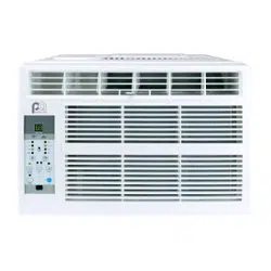
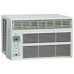
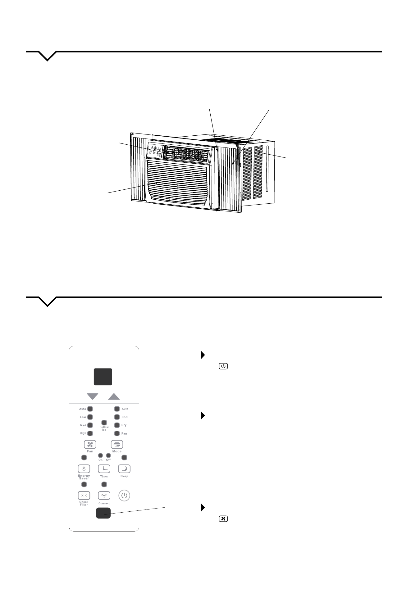
NOTE: (SSVM[OLWPJ[\YLZPU[OPZTHU\HSHYLMVYL_WSHUH[VY`W\YWVZLZVUS`;OLHJ[\HSZOHWLSVVRVM
[OLHPYJVUKP[PVULYW\YJOHZLKTH`ILZSPNO[S`KPɈLYLU[I\[[OLVWLYH[PVUZHUKM\UJ[PVUZHYLZPTPSHY
;OVYV\NOS`MHTPSPHYPaL`V\YZLSM^P[O[OLJVU[YVSWHULSZOV^UILSV^HUKHSSVMP[ZM\UJ[PVUZ(M[LY^HYKZMVSSV^[OLZ`TIVS
MVY[OLM\UJ[PVUZ`V\KLZPYL),-69,VWLYH[PUN[OL\UP[;OPZ\UP[JHUILJVU[YVSSLKI`[OL\UP[JVU[YVSVY[OLYLTV[L
control.
Remote Signal
Receptor
TO TURN UNIT ON OR OFF:
Press 656--I\[[VU[V[\YU[OL\UP[VUVYVɈ
NOTE: The unit will automatically initiate the Energy Saver
M\UJ[PVU\UKLY*663+9@HUK(<;6VUS`(<;6*66305.
HUK(<;6-(5TVKLZ
TO CHANGE TEMPERATURE SETTING:
Press
S
T
<7+6>5I\[[VU[VJOHUNL[OL
temperature setting.
NOTE: Press or hold either UP (
S
VY+6>5
T
) button
until the desired temperature is shown on the display. The
temperature will be automatically maintained anywhere
between 62°F (17°C) and 86°F (30°C). If you want the display
[VYLHK[OLHJ[\HSYVVT[LTWLYH[\YLZLL¸;V6WLYH[LVU-HU
6US`¹ZLJ[PVU
TO ADJUST FAN SPEEDS:
Press to select the Fan Speed in four steps: Auto, Low,
Med or High. Each time the button is pressed, the fan speed
PZZOPM[LK0U+9@TVKL[OLMHUZWLLKPZH\[VTH[PJHSS`JVU-
trolled at Low. For some models with heating capabilities, the
MHUZWLLKJHUUV[ILHKQ\Z[LK^OPSLPU/,(;TVKL
UNIT CONTROL PANEL
Heat indicator on models with
heating capabilities only.
19
14
SLEEP FEATURE:
Press SLEEP button to initiate the SLEEP
mode. In this mode, the selected temperature will
increase by 2°F (1°C) 30 minutes after the mode is
selected. The temperature will then increase (cooling)
or decrease (units with heating only) by another
2°F (1°C) after an additional 30 minutes. This new
temperature will be maintained for 6 hours before it
returns to the originally selected temperature. This
ends the SLEEP mode and the unit will continue
to operate as originally programmed. The SLEEP
mode program can be canceled at any time during
operation by pressing the SLEEP button again.
CHECK FILTER FEATURE:
Press CHECK FILTER button to initiate this
feature. This feature is a reminder to clean the Air
-PS[LYMVYTVYLLɉJPLU[VWLYH[PVU;OL3,+SPNO[^PSS
illuminate after 250 hours of operation. To reset after
JSLHUPUN[OLÄS[LYWYLZZ[OLCHECK FILTER button
HUK[OLSPNO[^PSSNVVɈ
ENERGY SAVER FEATURE:
Press ,5,9.@:(=,9 button to initiate this
function. This function is available on *663, +9@
and (<;6 (only (<;6*66305.and (<;6-(5)
modes. In this mode, the fan will continue to run for 3
TPU\[LZHM[LY[OLJVTWYLZZVYZO\[ZVɈ;OLMHU[OLU
cycles on for 2 minutes, at 10 minute intervals, until
the room temperature is above the set temperature,
H[^OPJO[PTL[OLJVTWYLZZVY[\YUZIHJRVUHUK
cooling starts.
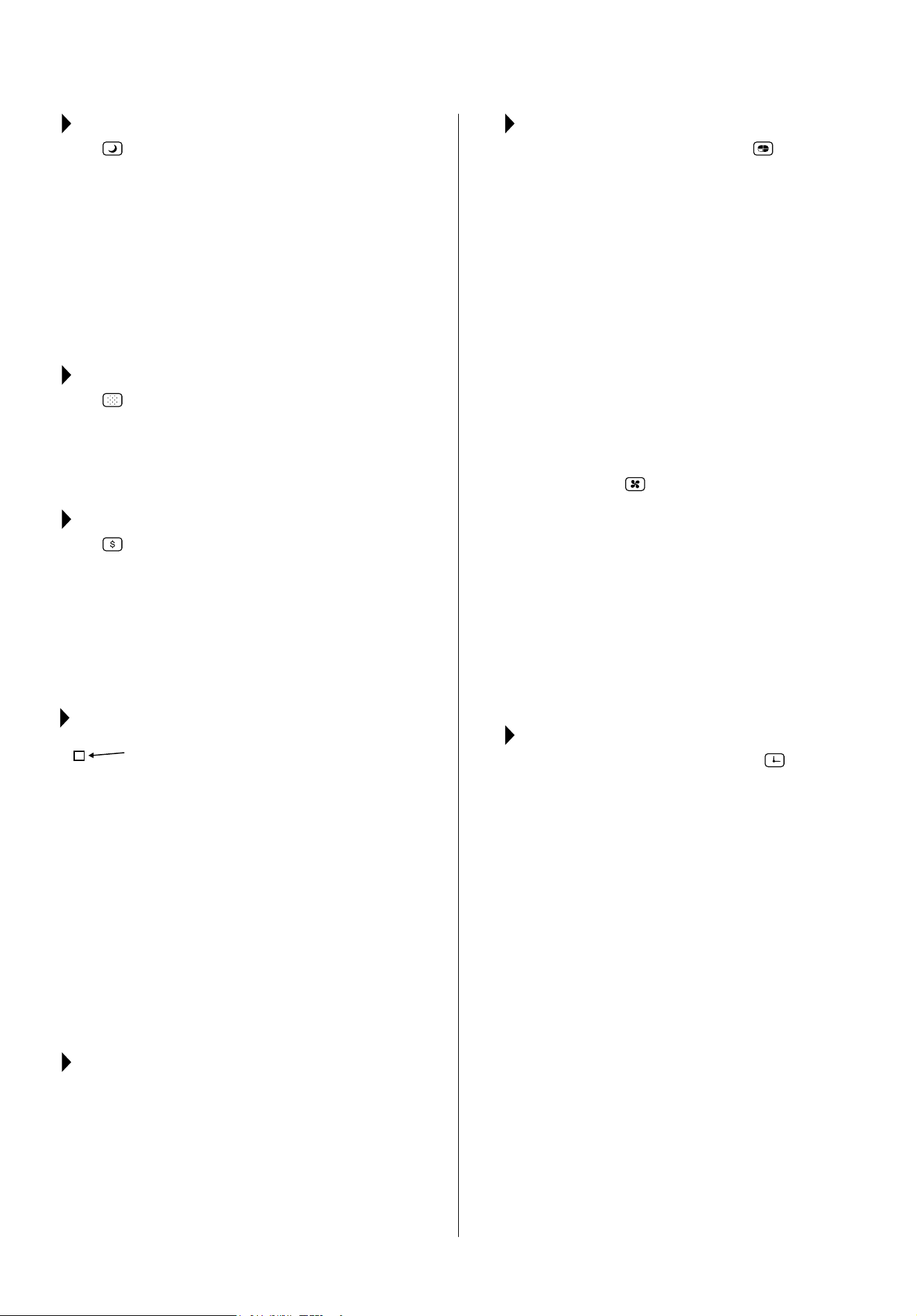
FOLLOW ME FEATURE:
This feature can ONLY be activated
from the remote control. The
remote control serves as a remote
thermostat, allowing for precise
temperature control at its location.
To activate the Follow Me feature, point the remote
control toward the unit and press the -6336>4,
button. The remote displays the actual temperature
at its location. The remote control will send this
signal to the air conditioner every 3 minutes until the
-6336>4, button is pressed again. If the unit does
not receive the Follow Me signal during any 7 minute
interval, the unit will beep to indicate use of the
Follow Me feature has ended. The actual temperature
can be displayed on the unit by pressing the FAN
VUS`TVKL>OLUPU*663TVKL[OL\UP[KPZWSH`
indicates the set temperature.
TO SELECT THE OPERATING MODE:
To choose operating mode, press the 46+,
button. Each time you press the button, a mode is
ZLSLJ[LKPUHZLX\LUJL[OH[NVLZMYVT(<;6*663
+9@, HEAT (for units with heating function) and FAN.
The indicator light will be illuminated and remain on
once the mode is selected. The unit will automatically
initiate the Energy Saver function under COOL, DRY, and
AUTO (only AUTO-COOLING and AUTO-FAN) modes.
TO OPERATE AUTO FEATURE:
When you set the air conditioner to (<;6 mode, it
will automatically select cooling, or fan only operation
depending on what temperature you have selected
and the room temperature. The air conditioner will
automatically control room temperature around the
temperature you set. In this mode, the fan speed
cannot be adjusted. It starts automatically at a speed
according to the room temperature.
TO OPERATE FAN ONLY:
Use this function (
) only when cooling is not
desired, such as for room air circulation or to exhaust
stale air. (Remember to open the vent during this
M\UJ[PVUI\[RLLWP[JSVZLKK\YPUNJVVSPUNMVY
TH_PT\TJVVSPUNLɉJPLUJ`@V \ JHUJOVVZLHU`
fan speed you prefer. During this function, the display
will show the actual room temperature, not the set
temperature as in the cooling mode.
TO OPERATE ON DRY MODE:
In this mode, the air conditioner will reduce air
humidity. If the space is a closed or sealed area,
some degree of cooling will continue.
TIMER: AUTO START/STOP FEATURE:
࡛ >OLU[OL\UP[PZVUVYVɈÄYZ[WYLZZ TIMER
I\[[VU;OL;04,965PUKPJH[VYSPNO[PSS\TPUH[LZ0[
indicates the Auto Start program is initiated.
࡛ >OLU;04,965PZKPZWSH`LKWYLZZPUN[OLTIMER
I\[[VUHNHPUPSS\TPUH[LZ[OL;04,96--PUKPJH[VY
indicating that the Auto Stop program is initiated.
࡛ 7YLZZVYOVSK[OL<7VY+6>5I\[[VU[VJOHUNL
the Auto time by 0.5 hour increments, up to 10
hours, then by 1 hour increments, up to 24 hours.
The control will count down the time remaining
until start.
࡛ ;OLZLSLJ[LK[PTL^PSSYLNPZ[LYPUZLJVUKZHUK
[OLZ`Z[LT^PSSH\[VTH[PJHSS`YL]LY[IHJR[V
displaying the previous temperature setting or the
room temperature (depending on whether the unit
PZWV^LYLKVUVYVɈHUK[OLTVKLP[PZPU
࡛ ;\YUPUN[OL\UP[65VY6--H[HU`[PTLVY
HKQ\Z[PUN[OL[PTLYZL[[PUN[V^PSSJHUJLS[OL
(\[V:[HY[:[VWWYVNYHT
A NOTE ABOUT THE TIMER:
When you set the timer, the
\UP[^PSSVUS`NVVUVUJLHUKVɈVUJL0M`V\^HU[[OL
HPYJVUKP[PVULY[VJ`JSLVUHUKVɈIHZLKVUKLZPYLK
room temperature, you do not need to set the timer.
Instead, set your desired temperature and the unit will
J`JSLVUHUKVɈIHZLKVU[OH[[LTWLYH[\YLZL[[PUN
Light
Flashing
Follow
Me
CONNECT BUTTON:
When you use the wireless function for the first time, press
this button for 3 seconds to initiate the wireless connection
mode. The LED display shows “AP” to indicate you can start
the wireless connection procedure. Please see your
wireless app manual for instructions to set up your app and
wireless connection. If the connection is successful within 8
minutes the unit will exit the setup mode and the CONNECT
indicator will illuminate. If unable to connect within 8 minutes
the unit will exit the connection mode, please start from the
beginning to re-connect.
20
15
DISPLAY:
Shows the set temperature in °F or °C and the Auto-
timer settings. While in FAN only mode, it shows the
room temperature.
ERROR CODES:
AS - Room Temperature Sensor Error - Unplug the
\UP[HUKWS\NP[IHJRPU0MLYYVYYLWLH[ZJHSS
Consumer Services at 844-472-2473.
HS - Electric Heating Sensor Error - Unplug the
\UP[HUKWS\NP[IHJRPU0MLYYVYYLWLH[ZJHSS
Consumer Services at 844-472-2473.
࡛ Evaporator Temperature Sensor Error - Unplug
[OL\UP[HUKWS\NP[IHJRPU0MLYYVYYLWLH[ZJHSS
Consumer Services at 844-472-2473.
NOTE: If an error code occurs in FAN only mode, the
\UP[^PSSKPZWSH`¸36¹SVVZLJVUULJ[PVUVY¸/0¹
(short circuit).
NOTE
:
0M[OL\UP[IYLHRZVɈ\UL_WLJ[LKS`K\L[VWV^LYILPUN
cut, it automatically will restart with the previous
function setting when the power resumes.
AIR DIRECTIONAL LOUVERS:
<ZL[OL^H`KPYLJ[PVUHSSV\]LYZ[VKPYLJ[[OLHPYÅV^
up or down and left or right throughout the room as
ULLKLK7P]V[OVYPaVU[HSSV\]LYZ\U[PS[OLKLZPYLK\W
down direction is obtained.
Move the levers from side to side until the desired
3LM[9PNO[KPYLJ[PVUPZVI[HPULK
ADDITIONAL THINGS YOU
SHOULD KNOW:
࡛ ;OL*VVSJPYJ\P[OHZHUH\[VTH[PJTPU\[L
[PTLKLSH`LKZ[HY[PM[OL\UP[PZ[\YULKVɈHUKVU
X\PJRS`(M[LY\UP[PZ[\YULKVɈSLH]L[OL\UP[VɈ
for a minimum of 3 minutes before attempting to
[\YUIHJRVU;OPZWYL]LU[ZV]LYOLH[PUNVM[OL
JVTWYLZZVYHUKWVZZPISLJPYJ\P[IYLHRLY[YPWWPUN
The fan will continue to run during this time.
࡛ ;OLJVU[YVSPZJHWHISLVMKPZWSH`PUN[LTWLYH[\YLPU
degrees Fahrenheit or degrees Celsius. To convert
from one to the other, press and hold the left and
right ;,47;04,9 buttons (
S
and
T
) at the
same time for 3 seconds.
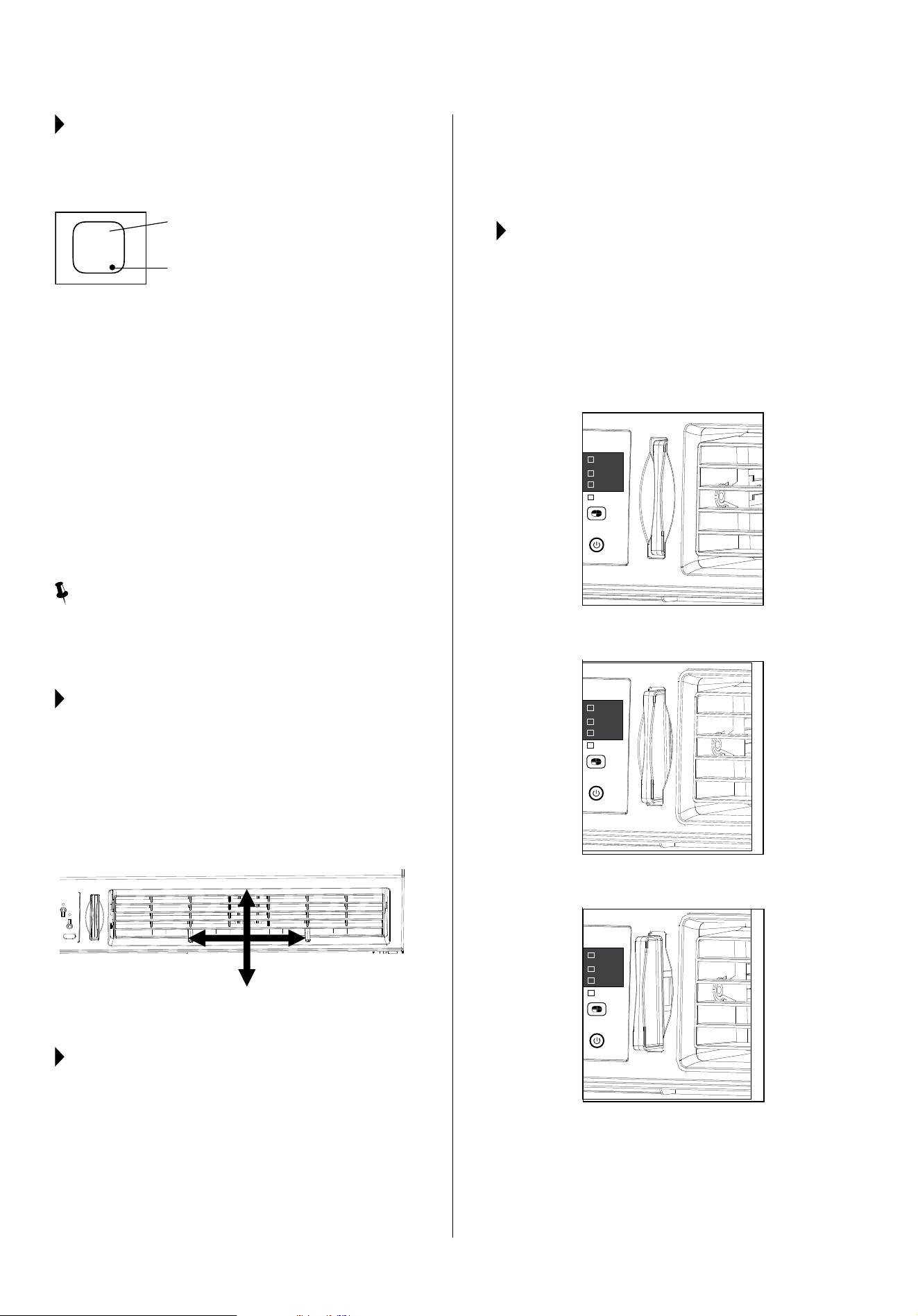
FRESH AIR VENT CONTROL
(on some models):
The Fresh Air Vent allows the air conditioner to:
1. Recirculate inside air (Vent Closed - Fig. A)
+YH^MYLZOHPYPU[V[OLYVVT=LU[6WLU-PN)
3. Exchange air from the room and draw fresh air into
[OLYVVT=LU[HUK,_OH\Z[6WLU-PN*
Air Direction (4-way)
Air Directional Louvers
Display
Evaporator Temperature Sensor Error
Auto
Cool
Dry
Fan
Mode
Auto
Cool
Dry
Fan
Mode
Auto
Cool
Dry
Fan
Mode
Fig. A (VENT CLOSED)
Fig. B (VENT OPEN)
Fig. C (VENT AND EXHAUST OPEN)
21
16
CARE AND CLEANING
CAUTION
*SLHUHPYJVUKP[PVULYVJJHZPVUHSS`[VRLLWP[SVVRPUNHUKVWLYH[PUNSPRLUL^
Be sure to unplug the unit before cleaning to prevent shock or fire hazards.
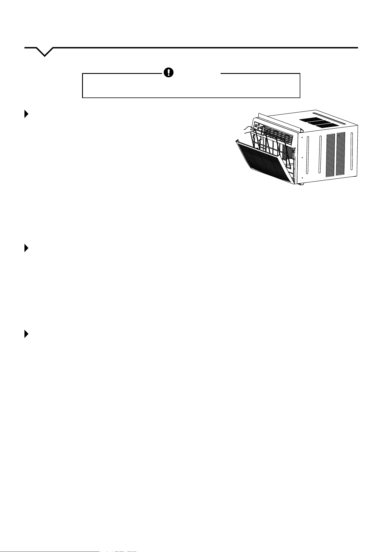
AIR FILTER CLEANING
;OLHPYÄS[LYZOV\SKILJSLHULKH[SLHZ[L]LY`[^V^LLRZVYHZ
ULJLZZHY`;YHWWLKWHY[PJSLZPU[OLÄS[LYJHUI\PSK\WHUKJH\ZLHU
accumulation of frost on the cooling coils.
࡛ 7\ZO[OL]LU[OHUKSL[V[OL=LU[*SVZLKWVZP[PVU^OLYLHWWSPJHISL
࡛ 6WLU[OLMYVU[WHULS
࡛ .YHZW[OLÄS[LYI`[OLJLU[LYHUKW\SS\WHUKV\[
࡛ >HZO[OLÄS[LY\ZPUNSPX\PKKPZO^HZOPUNKL[LYNLU[HUK^HYT^H[LY
9PUZLÄS[LY[OVYV\NOS`
࡛ .LU[S`ZOHRLL_JLZZ^H[LYMYVT[OLÄS[LY)LZ\YL[OLÄS[LYPZ
thoroughly dry before replacing.
࡛ (ZHUHS[LYUH[P]L[V^HZOPUN[OLÄS[LY]HJ\\T[OLÄS[LYJSLHU
NOTE: Never use hot water over 104°F (40°C) to clean the air filter.
Never attempt to operate the unit without the air filter.
CABINET CLEANING
࡛ )LZ\YL[V\UWS\N[OLHPYJVUKP[PVULY[VWYL]LU[ZOVJRVYÄYLOHaHYK
The cabinet and front may be dusted with an oil-free cloth or with
HJSV[OKHTWLULKPUHZVS\[PVUVM^HYT^H[LYHUKTPSKSPX\PK
dishwashing detergent. Rinse thoroughly and wipe dry.
࡛ 5L]LY\ZLOHYZOJSLHULYZ^H_VYWVSPZOVU[OLJHIPUL[MYVU[
࡛ )LZ\YL[V^YPUNL_JLZZ^H[LYMYVT[OLJSV[OILMVYL^PWPUN[OL
controls. Excess water in or around the controls may cause damage
to the air conditioner.
࡛ 7S\NPUHPYJVUKP[PVULYHM[LY\UP[OHZKYPLKJVTWSL[LS`
WINTER STORAGE
If air conditioner will be stored during the winter, remove it carefully
from the window according to the installation instructions. Cover it with
plastic or return it to the original carton.
ALWAYS STORE UNIT IN AN UPRIGHT POSITION AND IN A COOL,
DRY LOCATION.
22

17
NOTE
(OPNOS`YLJVTTLUKLK[YV\ISLZOVV[MVYHU`PZZ\LPUNLULYHSJVUZPZ[ZVM[\YUPUNVɈ\UP[HUK\UWS\NNPUNMVY
minutes. It is also recommended to try another wall outlet. For further assistance, contact Consumer Services at
844-472-2473.
TROUBLESHOOTING
BEFORE CALLING FOR SERVICE, PLEASE REVIEW THE CHART BELOW
ISSUE POSSIBLE CAUSES
AIR CONDITIONER NOT
COOLING ROOM, OR NOT BLOWING
COLD AIR
)LZ\YL\UP[PZUV[[VVSHYNLVY[VVZTHSSMVY[OLHYLHVM[OLYVVT
=LYPM`[OH[HSSKVVYZ^PUKV^ZJ\Y[HPUZHUKHU`V[OLYVWLUPUNZHYLJSVZLKVɈ
Verify nothing is obstructing the front grille of unit, such as curtains, etc.
(SSV^LUV\NO[PTLMVYYVVT[VJVVSLZWLJPHSS`PMV\[ZPKL[LTWPZ]LY`OPNO
*OLJR[OH[[OLÄS[LYPZUV[KPY[`HUKSV\]LYZHYLVWLUHSS[OL^H`HUKISV^PUNPU[OL
desired direction.
*OLJR[OH[\UP[PZZL[[V*663TVKLHUK[OH[[LTWLYH[\YLPZKV^ULUV\NOI\[
not too low).
0M\UP[PZULHYHOLH[ZV\YJLZ\JOHZHZ[V]LL[J[OLUYLSVJH[L\UP[
0MHPYJVTPUNMYVT\UP[PZJVVS[V[OL[V\JO[OLU\UP[PZ^VYRPUNWYVWLYS`"WSLHZL
KV\ISLJOLJR[OLÄYZ[[OYLLI\SSL[WVPU[ZHIV]L
0M\ZPUN-VSSV^4LYLTV[LMLH[\YLTV]LYLTV[LH^H`MYVT\UP[
;LTWLYH[\YLZLUZVYILOPUKHPYÄS[LY[V\JOPUNJVSKJVPS;OLZL[^VLSLTLU[ZZOV\SK
not be touching. Carefully straighten tube away from coil.
<UWS\N\UP[MVYH[SLHZ[TPU\[LZ-VSSV^9LZL[PUZ[Y\J[PVUZVUWS\N
AIR CONDITIONER COOLING
BUT ROOM IS TOO WARM - ICE
FORMING ON COOLING COIL
BEHIND DECORATIVE FRONT
6\[KVVY[LTWLYH[\YLPZILSV^¢-¢*;VKLMYVZ[[OLJVPSZL[[V-(5
only mode.
(PYÄS[LYTH`ILKPY[`*SLHUÄS[LY9LMLY[V*HYLHUK*SLHUPUNZLJ[PVU;VKLMYVZ[
set to FAN only mode.
;OLYTVZ[H[PZZL[[VVJVSKMVYUPNO[[PTLJVVSPUN;VKLMYVZ[[OLJVPSZL[[V-(5
only mode. Then, set temperature to a higher setting.
AIR CONDITIONER CYCLING ON
AND OFF TOO FREQUENTLY OR
NOT ENOUGH
)LZ\YL\UP[PZUV[[VVSHYNLVY[VVZTHSSMVY[OLHYLHVM[OLYVVT
9LTV]LNYPSSLHUKTHRLZ\YL[OL[LTWLYH[\YLZLUZVYPZUV[[VVJSVZL[V[OLJVPSZ
These two elements should not be touching. Carefully straighten tube away
from coil.
4HRLZ\YLUV[OPUNPZISVJRPUN[OLNYPSSLVYZPKL]LU[Z
4HRLZ\YL[OLYLPZUVKPY[VYKLIYPZPUZPKL[OL\UP[VYVU[OLÄS[LY
UNIT WILL NOT TURN ON
9LZL[JPYJ\P[IYLHRLY4HRLZ\YL[OLYLHYLUV[[VVTHU`P[LTZPLSHTWZ;=»Z
L[J^VYRPUNVɈ[OLZHTLIYLHRLY
*OLJRWS\NJVUULJ[PVU
0MWS\NPZVWLYH[PUNVUHUVUVɈZ^P[JOILZ\YL[OH[[OLZ^P[JOPZºVU»
;Y`WS\NNPUN\UP[PU[VHUV[OLYV\[SL[
<UWS\N\UP[MVYH[SLHZ[TPU\[LZ-VSSV^9LZL[PUZ[Y\J[PVUZVUWS\N
UNIT BLOWS FUSES OR POPS
CIRCUIT BREAKER
4HRLZ\YL[OLYLHYLLUV\NOH]HPSHISLHTWZVU[OLJPYJ\P[MVY[OLHPYJVUKP[PVULY
3HYNL\UP[Z^OPJOY\UVUH]^PSSYLX\PYLHKLKPJH[LKVYHTWJPYJ\P[
AIR CONDITIONER IS
MAKING NOISES
*OLJR[VILZ\YL[OL\UP[PZMYLLMYVTKLIYPZZ\JOHZSLH]LZZ[PJRZL[J=LYPM`
nothing is obstructing the unit.
*OLJR[OLMHUISHKLMVYJYHJRZVYJOPWZ
4HRLZ\YL[OL\UP[PZWYVWLYS`HUKZLJ\YLS`TV\U[LKPUZPKL[OL^PUKV^VY^HSS
*SLHU[OLHPYÄS[LY
WATER PUDDLES INSIDE UNIT OR IS
COMING INTO ROOM
(KQ\Z[[OLZSVWLVM[OL\UP[ZV[OH[P[KYHPUZKV^U^HYK[V^HYK
[OLL_[LYPVYVM[OL
home. (See Installation Instructions.)
4HRLZ\YL[OH[[OLYLPZUVKLIYPZISVJRPUN[OLKYHPUHNLHYLHVM[OL\UP[
WATER DRIPPING OUTSIDE
<UP[PZYLTV]PUNHSHYNLX\HU[P[`VMTVPZ[\YLMYVTHO\TPKYVVT;OPZPZUVYTHS
during excessively humid days.
REMOTE SENSING / FOLLOW ME
DEACTIVATING PREMATURELY
9LTV[LJVU[YVSUV[SVJH[LK^P[OPUYHUNL7SHJLYLTV[LJVU[YVS^P[OPUM[HUK
180º radius of the front of the unit.
9LTV[LJVU[YVSZPNUHSVIZ[Y\J[LK9LTV]LVIZ[Y\J[PVU
23
844-4PA-AIRE | 844-472-2473 | support@perfectaire.us
CANADA SUPPORT 877-997-2473 | supportcanada@perfectaire.us
www.perfectaire.us
5401 Dansher Road
Countryside, IL 60525
Printed in China | 1022_M996
THANK YOU FOR YOUR PURCHASE!
As a small business, reviews are everything!
We’d love to hear how you are enjoying your Perfect Aire product!
Please take a minute to tell us (and others) about your experience.
Thanks (again!)
SCAN CODE TO
LEAVE A REVIEW