
INSTALLATION
INSTRUCTIONS
DF GTG (90 cm) models
2
INSTALLATION INSTRUCTIONS
Before you start please read the instructions.
Planning your installation will save you time and
effort.
6
FAILURE TO INSTALL APPLIANCES
CORRECTLY IS DANGEROUS AND
COULD LEAD TO PROSECUTION.
6
Installation must be carried out by
a qualified installer or engineer. We
recommend that the appliance is
connected by a competent person who
is a member of a “Competent Person
Scheme” who will comply with the
required regulations.
4
Our policy is one of constant
development and improvement,
therefore we cannot guarantee the strict
accuracy of all of our illustrations and
specifications. Changes may have been
made subsequent to publishing.
Please keep to the following points most carefully;
6
Although every care has been taken to
ensure this appliance has no sharp edges,
we recommend that you wear protective
gloves when installing and moving this
appliance. This will prevent injury.
6
Ensure that you route all mains cables
well clear of any adjacent heat source.
6
The space for air circulation, located
underneath and at the back of the hob
improves its reliability by ensuring that it
will cool down, efficiently.
CONTENTS
REGULATIONS AND STANDARDS 3
BEFORE INSTALLATION 4
DIMENSIONS AND CLEARANCES 6
CONNECTION TO THE ELECTRICITY SUPPLY 8
CONNECT TO THE GAS SUPPLY 10
COMMISSIONING 11

3
REGULATIONS AND STANDARDS
This cooker must be installed in accordance with the
instructions in this booklet, the relevant national
regulations and with the local gas and electricity
supply companies’ requirements. Before installation,
make sure that the cooker is suitable for your gas type
and supply voltage. See the data badge.
This appliance is not connected to a combustion
evacuation device. It shall be installed and connected
in accordance with current installation regulations.
Particular attention shall be given to the relevant
requirements regarding ventilation.
In your own interest and that of safety, it is the law
that all gas appliances be installed and serviced by
competent persons. Failure to install the appliance
correctly could invalidate any warranty or liability
claims and lead to prosecution.
VENTILATION REQUIREMENTS
The use of a gas cooking appliance results in the
production of heat and moisture in the room in
which it is installed. Ensure that the kitchen is well
ventilated: keep natural ventilation holes open or
install a mechanical ventilation device (mechanical
extractor hood). Prolonged intensive use of the
appliance may call for additional ventilation, for
example, opening of a window, or more effective
ventilation, for example increasing the level of
mechanical ventilation where present.
∙ The room containing the appliance should have an
air supply in accordance with all relevant national
regulations and codes of practice in force in the
country where it is intended to be installed.
∙ All rooms require an openable window, or
equivalent, and some rooms will also require a
permanent vent.
∙ For room volumes up to 5 m³ an air vent of 100 cm²
is required.
∙ If the room has a door that opens directly to the
outside, or the room exceeds 10m³, NO AIR VENT is
required.
∙ For room volumes between 5 m³ and 10 m³ an air
vent of 50 cm² is required.
∙ If there are other fuel burning appliances in the
same room, BS 5440-2:2009 should be consulted to
determine the air vent requirements.
∙ This appliance must not be installed in a bed
sitting room of less than 20m³ or in a bathroom or
shower room.
∙ Windows and permanent vents should therefore
not be blocked or removed without first consulting
a qualified installer or engineer.
4
BEFORE INSTALLATION
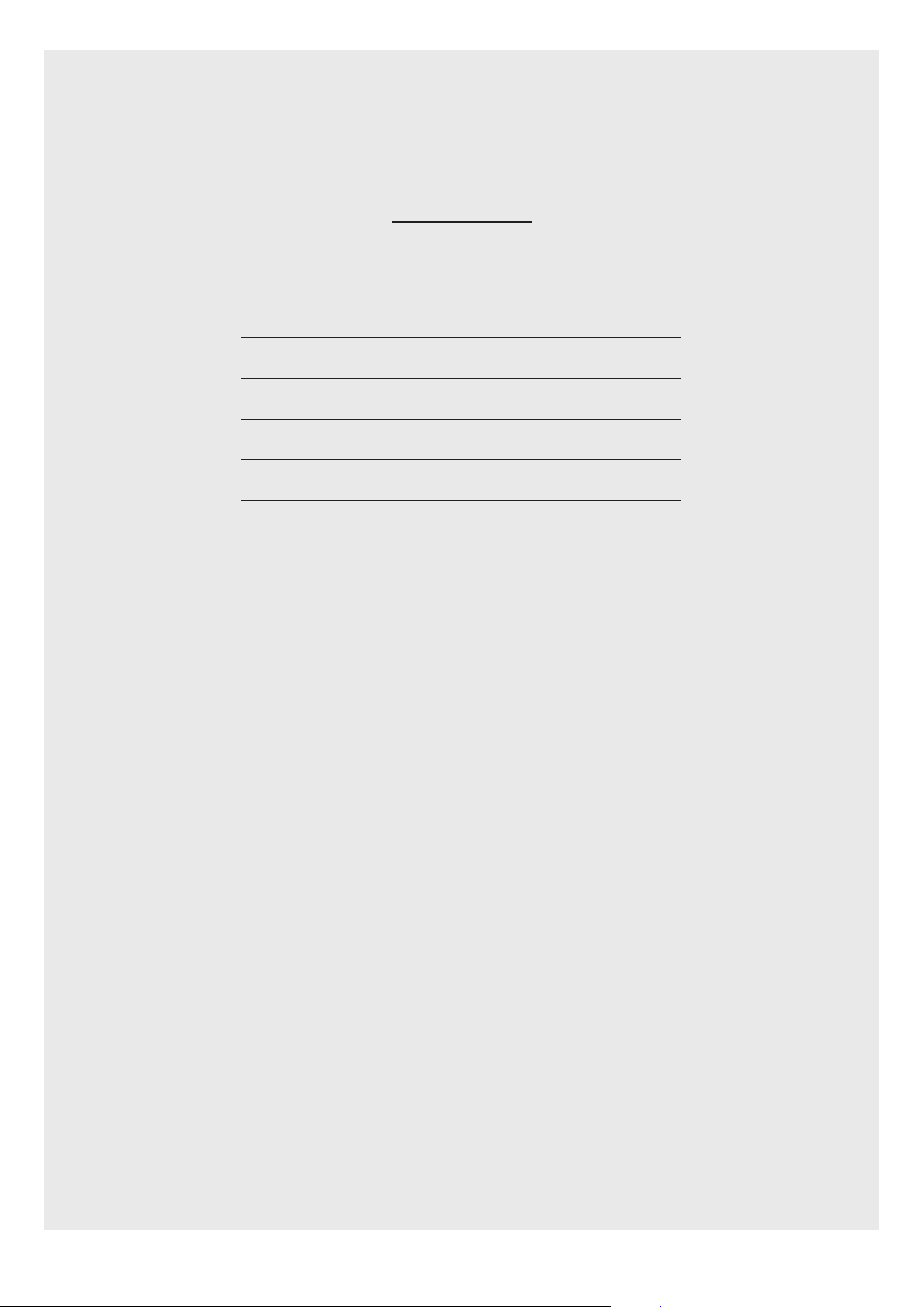
LEVELLING YOUR COOKER
1. Place a spirit level on a baking sheet onto an oven
shelf.
2. The cooker is fitted with levelling feet (1). Level your
cooker to your desired height using the levelling
feet at the front and rear of the cooker.
1
Rear of cooker
REAR WHEELS (IF FITTED)
Adjustment of the wheel height can be made with a
screw driver, through the hexagonal hole in the front
plinth.
FITTING THE PLINTH (IF
APPLICABLE)
1. Ensure the appliance is raised to a height of 915
mm or above using adjusting feet (A) before
beginning.
2. Open the appliance doors and loosen screw (C), do
not remove the screw entirely. If your appliance
has a storage drawer at the bottom, you access the
screws through holes located at the base of the
drawer after lifting the mat.
3. Fit plinth (B) and secure using screw (C).
C
A
B
5
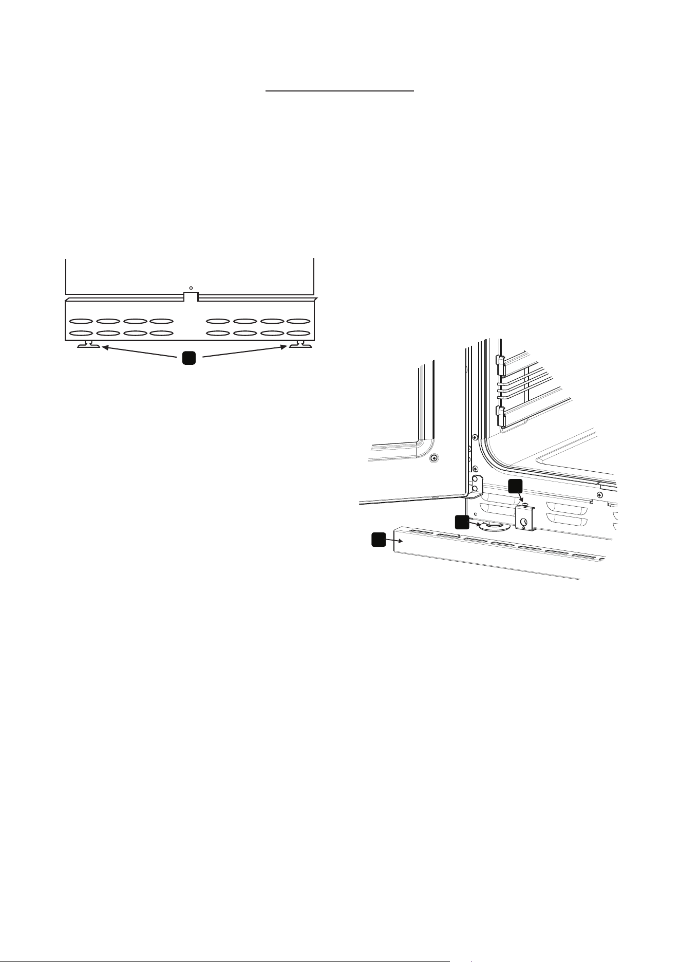
FITTING THE TOWEL RAIL (IF APPLICABLE)
On the towel rail there are two holes, top (A) and
bottom (B), these holes have corresponding holes on
the fascia at each end.
The 2x longer screws are designed for the top hole (A),
whereas the remaining screw just goes through the
bottom hole (B). Both screws are M6 screws. Using the
Allen key provided, tighten the screws making sure
that the towel rail is flush to the fascia, but not over
tightened.
A
B
Plinth
cover
Stainless 013342453
Black 013342454
6
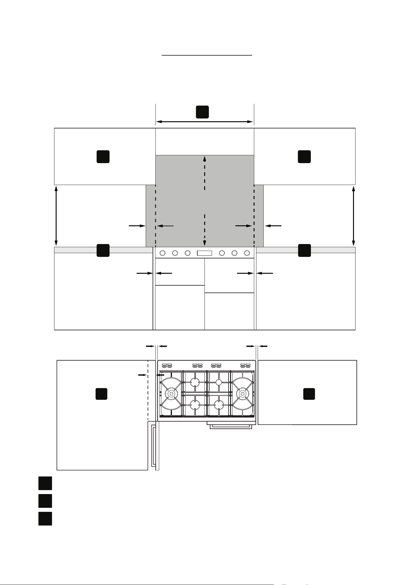
DIMENSIONS AND CLEARANCES
CUPBOARD / HOOD CLEARANCES
90mm
400mm
90mm
10mm
400mm
min
650mm
10mm
B
C C
B
A
10mm 10mm
60mm
C C
A
Nominal width of the hob
B
Wall Unit
C
Worktop
7
6
No shelf or overhang of combustible
material should be closer than 650 mm
above the hob.
4
If your appliance has a side opening door,
we recommend a side clearance of 60
mm to allow the oven door to fully open,
if placed up to a wall or cabinetry.
4
The cooker must have a side clearance
above hob level of 90mm up to a height
of 400 mm.
4
This cooker may be fitted flush to the
base units of your kitchen.
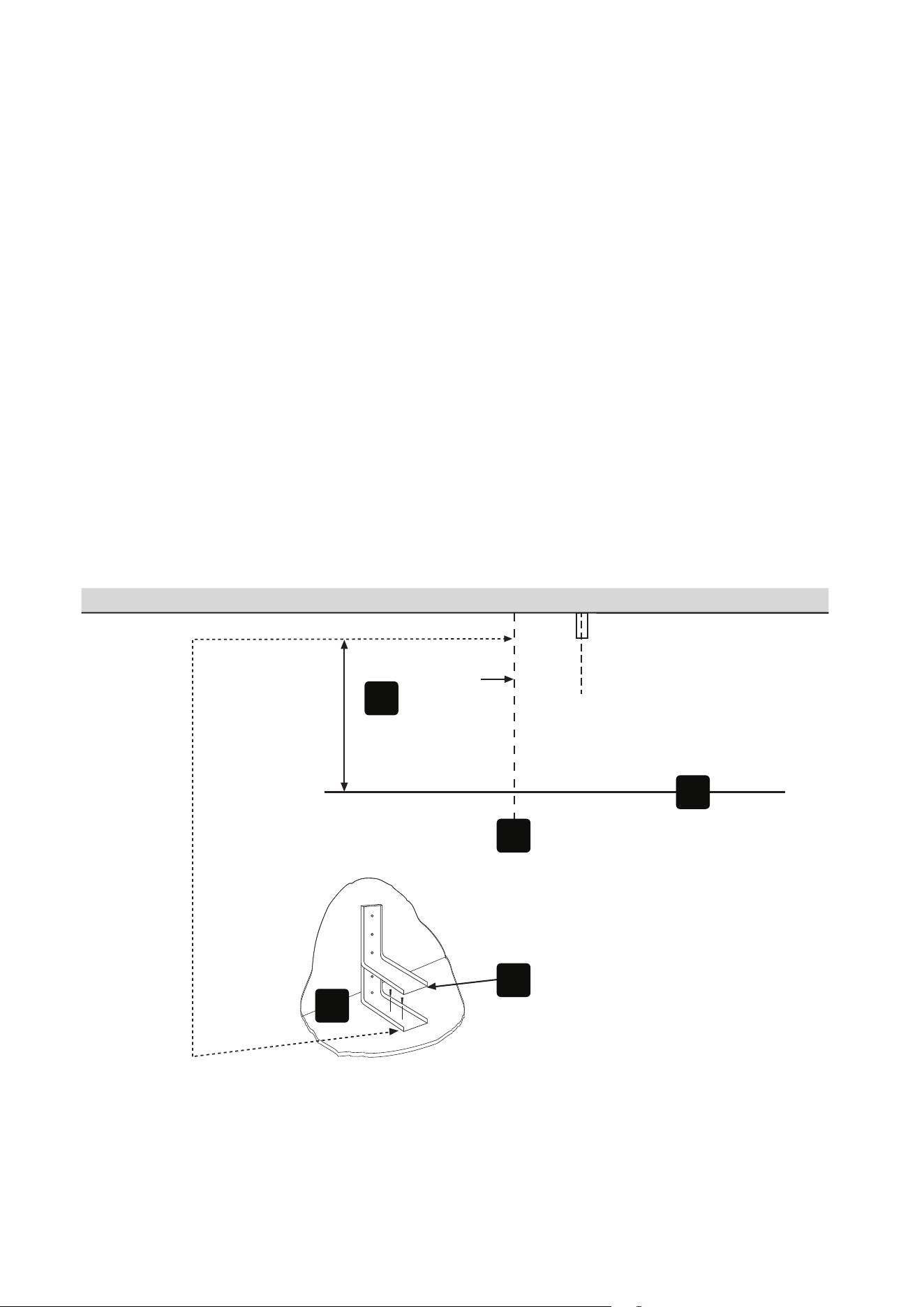
STABILITY BRACKET
If the cooker is fitted with a flexible connection, a
stability bracket should be fitted to engage in the back
of the cooker. A stability bracket can be bought from
your local supplier.
A stability bracket can be fitted as follows:
1. Place the cooker in the position and draw a PENCIL
LINE level with the front edge.
2. Mark the centre of the cooker to give the CENTRE
LINE for the bracket.
3. Remove the cooker and mark off 450 mm from the
PENCIL LINE to locate the front edge of the lower
bracket.
4. Fix the bracket to the floor. Measure from floor
level to engagement edge in the back of cooker and
add 3 mm.
5. Assemble the underside of the top part of the
bracket to this height.
Rear wall
(3)
450 mm
1
2
5
4
3
4
Underside of top bracket slots into
engagement edge in back of cooker.
4
Review stability bracket location
identified on rear of appliance and
position bracket accordingly.
8
CONNECTION TO THE ELECTRICITY SUPPLY
6
WARNING: This appliance must be
earthed.
This appliance must be fitted to a switch providing
all pole disconnection with a minimum contact
separation of 3 mm.
6
The terminal block screws and clamps
can be damaged by excessive tightening
and untightening. DO NOT USE POWER
TOOLS!
1. Gain access to the mains terminal by removing the
terminal block cover at the rear of the appliance.
2. Connection should be made with a suitable flexible
cable.
3. First strip the wires then push the cable through
the cable clamp.
4. Connect the cable to the terminal block and
tighten the cable clamp screws - see diagram.
5. Refit the terminal box cover.
6. Sufficient cable should be used to allow the cooker
to be pulled out, but must hang clear of the floor
so it does not become twisted or trapped when the
cooker is pushed back.
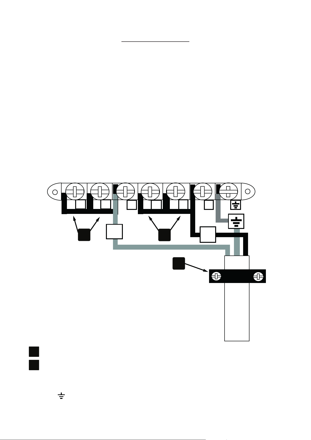
SINGLE PHASE CONNECTION (230 V ~50 HZ)
N
L
1 2
3 4 5
6
A
A
B
A
Shorting Links
B
Cable Clamp
7. Connect cable to the terminal block:
- L to terminal 3
- N to terminal 6
- Earth to terminal
8. Ensure shorting links are fitted between terminals
1-2, 2-3, 4-5 and 5-6.
9. Ensure all screws are fully tightened.
9
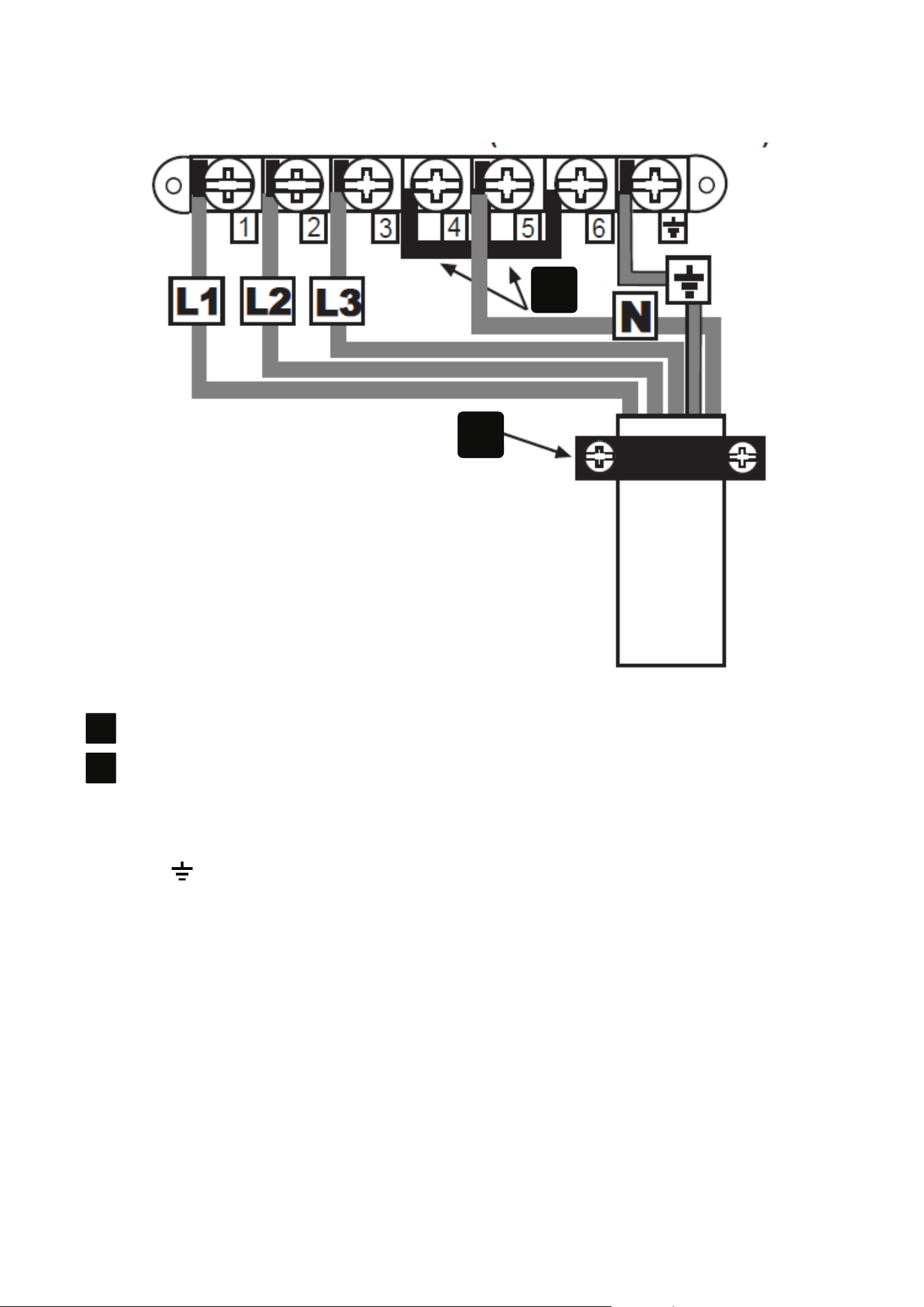
THREE PHASE CONNECTION (230/400 V 3N ~50 HZ)
A
B
A
Shorting Links
B
Cable Clamp
7. Connect cable to the terminal block:
- L1, L2 and L3 to terminals 1, 2 and 3
- N to terminal 5
- Earth to terminal
8. Remove shorting links 1-2 and 2-3.
9. Ensure shorting links are fitted between terminals
4-5 and 5-6.
10. Ensure all screws are fully tightened.

10
CONNECT TO THE GAS SUPPLY
The inlet to the cooker is ½” BSP internal situated at
the rear right corner. Fit the bayonet connection. This
should be located so as to ensure that the flexible
connector hose does not kink.
6
Under no circumstances should the
flexible connector be allowed to come
into contact with the vertical oven flue
tubes on the rear of the appliance.
Use a 900 mm - 1125 mm length of flexible connector.
Ensure that all pipework is of the correct rating for
both size and temperature.
Flexible connections should comply with the relevant
national regulations and codes of practice in force in
the country where it is intended to be installed. Parts of
the appliance likely to come into contact with a flexible
connector have a temperature rise of less than 70 °C.
After installation, make sure all connections are gas
sound.

11
COMMISSIONING
BURNER AERATION
All burners have fixed aeration and no adjustment is
possible.
PRESSURE SETTING
Pressure test point: Use the oven injector.
HOB BURNER
Turn the control knob to the ‘FULL ON’ position, wait a
second before pressing the ignition switch or holding
a lighted match or taper to the burner. Hold the
control knob in for 15 seconds. Do not hold the control
knob in for longer than 15 seconds. If the burner fails
to light within this time, release the control knob and
wait one minute before attempting further ignition.
CHECK THE OPERATION OF
ELECTRICAL COMPONENTS
Clock Programmer/Minute Minder
Check functions as described in the User Guide.
Oven light & Convection fan
Open the main oven door. Turn the main oven control
knob to the defrost setting. Check the oven light and
convection fan both come on. Turn control knob back
to ‘OFF’ position.
Cooling Fan
Turn the top oven control knob to the full power
setting.
Check that the cooling fan operates. Turn control knob
back to ‘OFF’ position and check cooling fan switches
off immediately.
4
Note: If the cooker does not perform
correctly, inform the customer of the
problem and put a warning notice on the
cooker. If the problem is dangerous, then
disconnect the cooker. If there is a fault,
then the customer should be advised to
contact the manufacturer’s local service
organisation or the retailer.
4
Before leaving the installation hand
over the User Guide to the customer

084021200
Stoney Lane, Prescot, Merseyside L35 2XW
Product Information Helpline
0344 248 4149
