
Barrier Gate
User Manual

Barrier Gate User Manual
i
About this Document
● This Document includes instructions for using and managing the Product. Pictures, charts,
images and all other information hereinafter are for description and explanation only.
● The information contained in the Document is subject to change, without notice, due to
firmware updates or other reasons. Please find the latest version of the Document at the
Hikvision website (https://www.hikvision.com). Unless otherwise agreed, Hangzhou Hikvision
Digital Technology Co., Ltd. or its affiliates (hereinafter referred to as "Hikvision") makes no
warranties, express or implied.
● Please use the Document with the guidance and assistance of professionals trained in
supporting the Product.
About this Product
● This product can only enjoy the after-sales service support in the country or region where the
purchase is made.
● If the product you choose is a video product, please scan the following QR code to obtain the
"Initiatives on the Use of Video Products", and read it carefully.
Acknowledgment of Intellectual Property Rights
● Hikvision owns the copyrights and/or patents related to the technology embodied in the
Products described in this Document, which may include licenses obtained from third parties.
● Any part of the Document, including text, pictures, graphics, etc., belongs to Hikvision. No part
of this Document may be excerpted, copied, translated, or modified in whole or in part by any
means without written permission.
● and other Hikvision’s trademarks and logos are the properties of Hikvision in
various jurisdictions.
● Other trademarks and logos mentioned are the properties of their respective owners.
LEGAL DISCLAIMER
● TO THE MAXIMUM EXTENT PERMITTED BY APPLICABLE LAW, THIS DOCUMENT AND THE
PRODUCT DESCRIBED, WITH ITS HARDWARE, SOFTWARE AND FIRMWARE, ARE PROVIDED "AS
IS" AND "WITH ALL FAULTS AND ERRORS". HIKVISION MAKES NO WARRANTIES, EXPRESS OR
IMPLIED, INCLUDING WITHOUT LIMITATION, MERCHANTABILITY, SATISFACTORY QUALITY, OR
FITNESS FOR A PARTICULAR PURPOSE. THE USE OF THE PRODUCT BY YOU IS AT YOUR OWN
RISK. IN NO EVENT WILL HIKVISION BE LIABLE TO YOU FOR ANY SPECIAL, CONSEQUENTIAL,
INCIDENTAL, OR INDIRECT DAMAGES, INCLUDING, AMONG OTHERS, DAMAGES FOR LOSS OF
BUSINESS PROFITS, BUSINESS INTERRUPTION, OR LOSS OF DATA, CORRUPTION OF SYSTEMS, OR
LOSS OF DOCUMENTATION, WHETHER BASED ON BREACH OF CONTRACT, TORT (INCLUDING

Barrier Gate User Manual
ii
NEGLIGENCE), PRODUCT LIABILITY, OR OTHERWISE, IN CONNECTION WITH THE USE OF THE
PRODUCT, EVEN IF HIKVISION HAS BEEN ADVISED OF THE POSSIBILITY OF SUCH DAMAGES OR
LOSS.
● YOU ACKNOWLEDGE THAT THE NATURE OF THE INTERNET PROVIDES FOR INHERENT SECURITY
RISKS, AND HIKVISION SHALL NOT TAKE ANY RESPONSIBILITIES FOR ABNORMAL OPERATION,
PRIVACY LEAKAGE OR OTHER DAMAGES RESULTING FROM CYBER-ATTACK, HACKER ATTACK,
VIRUS INFECTION, OR OTHER INTERNET SECURITY RISKS; HOWEVER, HIKVISION WILL PROVIDE
TIMELY TECHNICAL SUPPORT IF REQUIRED.
● YOU AGREE TO USE THIS PRODUCT IN COMPLIANCE WITH ALL APPLICABLE LAWS, AND YOU ARE
SOLELY RESPONSIBLE FOR ENSURING THAT YOUR USE CONFORMS TO THE APPLICABLE LAW.
ESPECIALLY, YOU ARE RESPONSIBLE, FOR USING THIS PRODUCT IN A MANNER THAT DOES NOT
INFRINGE ON THE RIGHTS OF THIRD PARTIES, INCLUDING WITHOUT LIMITATION, RIGHTS OF
PUBLICITY, INTELLECTUAL PROPERTY RIGHTS, OR DATA PROTECTION AND OTHER PRIVACY
RIGHTS. YOU SHALL NOT USE THIS PRODUCT FOR ANY PROHIBITED END-USES, INCLUDING THE
DEVELOPMENT OR PRODUCTION OF WEAPONS OF MASS DESTRUCTION, THE DEVELOPMENT
OR PRODUCTION OF CHEMICAL OR BIOLOGICAL WEAPONS, ANY ACTIVITIES IN THE CONTEXT
RELATED TO ANY NUCLEAR EXPLOSIVE OR UNSAFE NUCLEAR FUEL-CYCLE, OR IN SUPPORT OF
HUMAN RIGHTS ABUSES.
● IN THE EVENT OF ANY CONFLICTS BETWEEN THIS DOCUMENT AND THE APPLICABLE LAW, THE
LATTER PREVAILS.
© Hangzhou Hikvision Digital Technology Co., Ltd. All rights reserved.
Barrier Gate User Manual
iii
Symbol Conventions
The symbols that may be found in this document are defined as follows.
Symbol
Description
Danger
Indicates a hazardous situation which, if not avoided, will or could
result in death or serious injury.
Caution
Indicates a potentially hazardous situation which, if not avoided,
could result in equipment damage, data loss, performance
degradation, or unexpected results.
Note
Provides additional information to emphasize or supplement
important points of the main text.

Barrier Gate User Manual
iv
Contents
Chapter 1 Introduction ............................................................................................................... 1
1.1 Product Introduction ............................................................................................................. 1
1.2 Packing List ............................................................................................................................ 1
1.3 Barrier Gate Overview .......................................................................................................... 2
1.4 Machine Core Structure ........................................................................................................ 3
1.5 Boom Pole Overview ............................................................................................................. 4
1.5.1 Octagonal Straight Boom Pole ................................................................................... 4
1.5.2 Boom Pole with Strip Light ........................................................................................ 5
1.5.3 Anti-collision Cylinder Boom Pole ............................................................................. 6
1.5.4 Octagonal Telescopic Boom Pole ............................................................................... 7
1.5.5 Fence Boom Pole ........................................................................................................ 7
1.5.6 Folding Boom Pole ..................................................................................................... 8
Chapter 2 Installation ................................................................................................................. 9
2.1 Installation Environment ...................................................................................................... 9
2.2 Install Barrier Gate Host ........................................................................................................ 9
2.3 Install Boom Pole ................................................................................................................. 11
2.3.1 Install Octagonal Straight Boom Pole ...................................................................... 11
2.3.2 Install Boom Pole with Strip Light ........................................................................... 13
2.3.3 Install Anti-collision Cylinder Boom Pole ................................................................ 16
2.3.4 Install Octagonal Telescopic Boom Pole .................................................................. 18
2.3.5
Install Fence Boom Pole ........................................................................................ 20
2.3.6
Install Folding Boom Pole ...................................................................................... 24
2.4 Wiring ................................................................................................................................... 30
2.4.1 Connect to Power Supply ......................................................................................... 30
2.4.2 Connect to Supercapacitor Board ............................................................................ 31
2.4.3 Connect to Access ANPR Camera............................................................................. 32
2.4.4 Connect to Traffic Signal Light ................................................................................. 33
2.4.5 Connect to Anti-fall Radar........................................................................................ 34
2.4.6 Connect to Vehicle Detector .................................................................................... 38

Barrier Gate User Manual
v
2.4.7 Connect to Active Infrared Intrusion Detector ....................................................... 40
2.4.8 Connect to Arrow Indicator ..................................................................................... 41
2.4.9 Connect to Strip Light ............................................................................................... 42
2.4.10 Connect to Warning Light ...................................................................................... 43
Chapter 3 Parameters Configuration ......................................................................................... 45
3.1 Remote Control ................................................................................................................... 45
3.2
Set Parameters via Control Board Buttons ...................................................................... 45
3.2.1 Button Description ................................................................................................... 45
3.2.2
Operation Procedure ............................................................................................. 46
Chapter 4 Maintenance ............................................................................................................ 58
4.1 Adjust Boom Pole Balance .................................................................................................. 58
4.2 Change Boom Pole .............................................................................................................. 58
4.3 Change Spindle Rod and Spring .......................................................................................... 59
4.3.1 Spring and Spindle Rod Specifications .................................................................... 59
4.3.2 Change Spindle Rod.................................................................................................. 60
4.3.3 Change Spring ........................................................................................................... 62
4.4 Change Machine Core ......................................................................................................... 63
4.5 Left/Right Direction of Boom Pole...................................................................................... 64
4.6 Change Left/Right Direction of Machine Core ................................................................... 67
A.
FAQ .................................................................................................................................. 70
Barrier Gate User Manual
1
Chapter 1 Introduction
1.1 Product Introduction
Barrier gate (hereinafter referred to as “device”) is the entrance and exit management device to
limit motor vehicle passing. It can control the boom pole automatically via parking lot
management system. Or you can control the boom pole via buttons on remote controller.
Barrier gate is widely applicable to toll station, parking lot, the entrance and exit of community
and unit, etc.
1.2 Packing List
Please check if there is any damage of the package first. Refer to the table below for the packing
list of the barrier gate. According to the packing list, make sure no item is lost. After checking all
the items are included, you can continue to install the device.
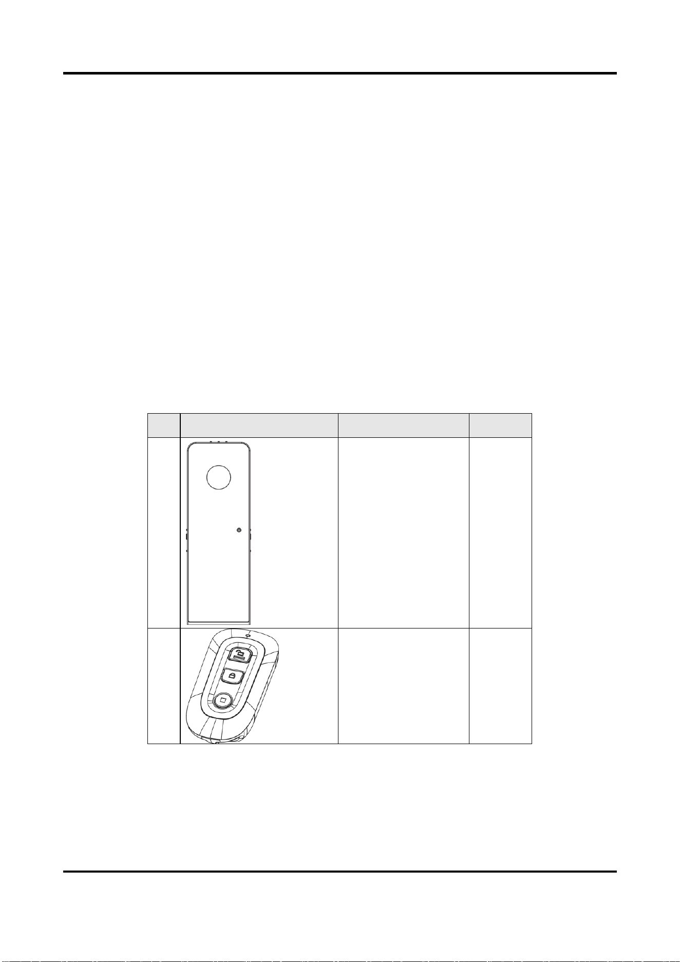
Table 1-1 Packing List
No.
Diagram
Name
Quantity
1
Barrier gate host
1
2
Remote controller
2
Barrier Gate User Manual
2
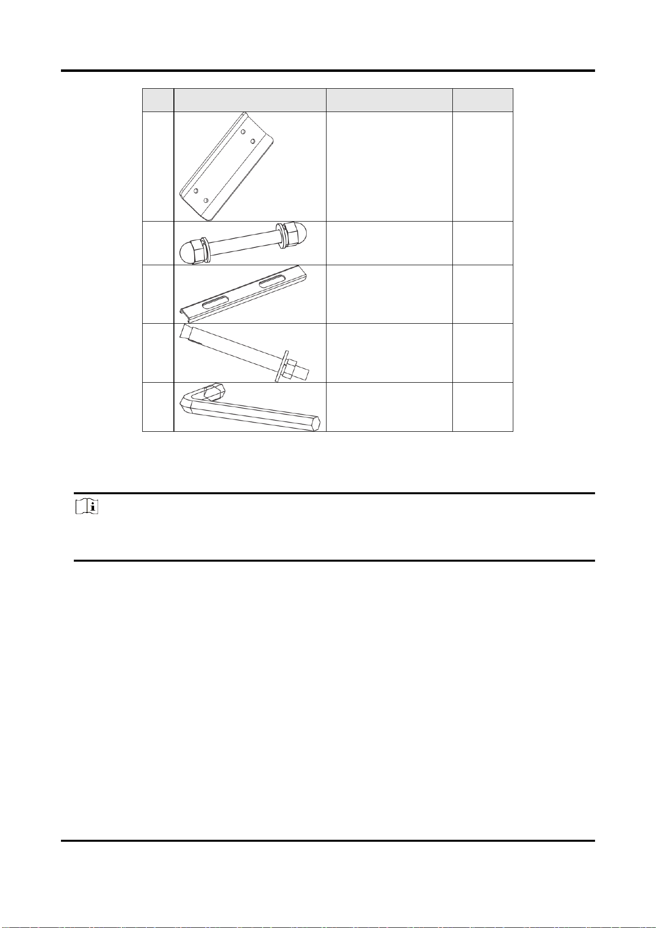
No.
Diagram
Name
Quantity
3
Chuck
1
4
Spindle rod screw set
4
5
Layer
2
6
Expansion screw
4
7
L-type wrench
1
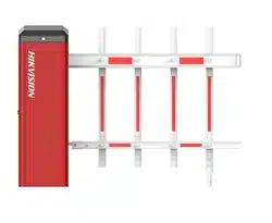
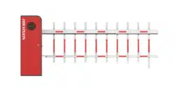
1.3 Barrier Gate Overview
Note
The appearances of the devices vary with different models. The figure below just takes an
example. Refer to the actual device for details.
Barrier Gate User Manual
3
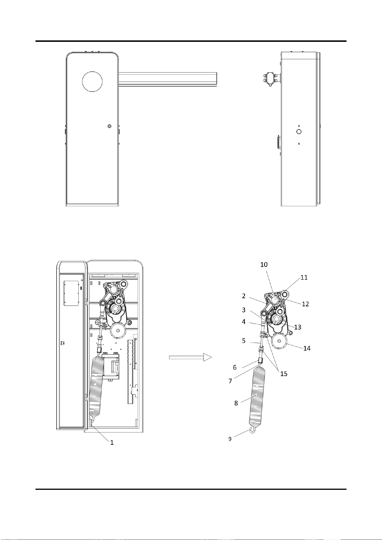
Figure 1-1 Barrier Gate Overview
1.4 Machine Core Structure
After you open the front cover, you can see the machine core of the device host.
Figure 1-2 Machine Core Structure
Barrier Gate User Manual
4
Table 1-2 Machine Core Component Description
No.
Description
No.
Description
1
Spring hook hole
9
Spring hook
2
Rocker
10
Cap screw to tighten the output shaft
3
Machine core limited block
11
Output shaft
4
Spring upper pull rod
12
Linkage arm
5
Spring extension nut
13
Crank arm
6
Spring lower pull rod
14
Hand wheel
7
Spring pull rod
15
Lock nuts and spring washers to tighten
the spring upper and lower pull rods
8
Spring
1.5 Boom Pole Overview
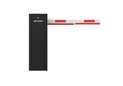
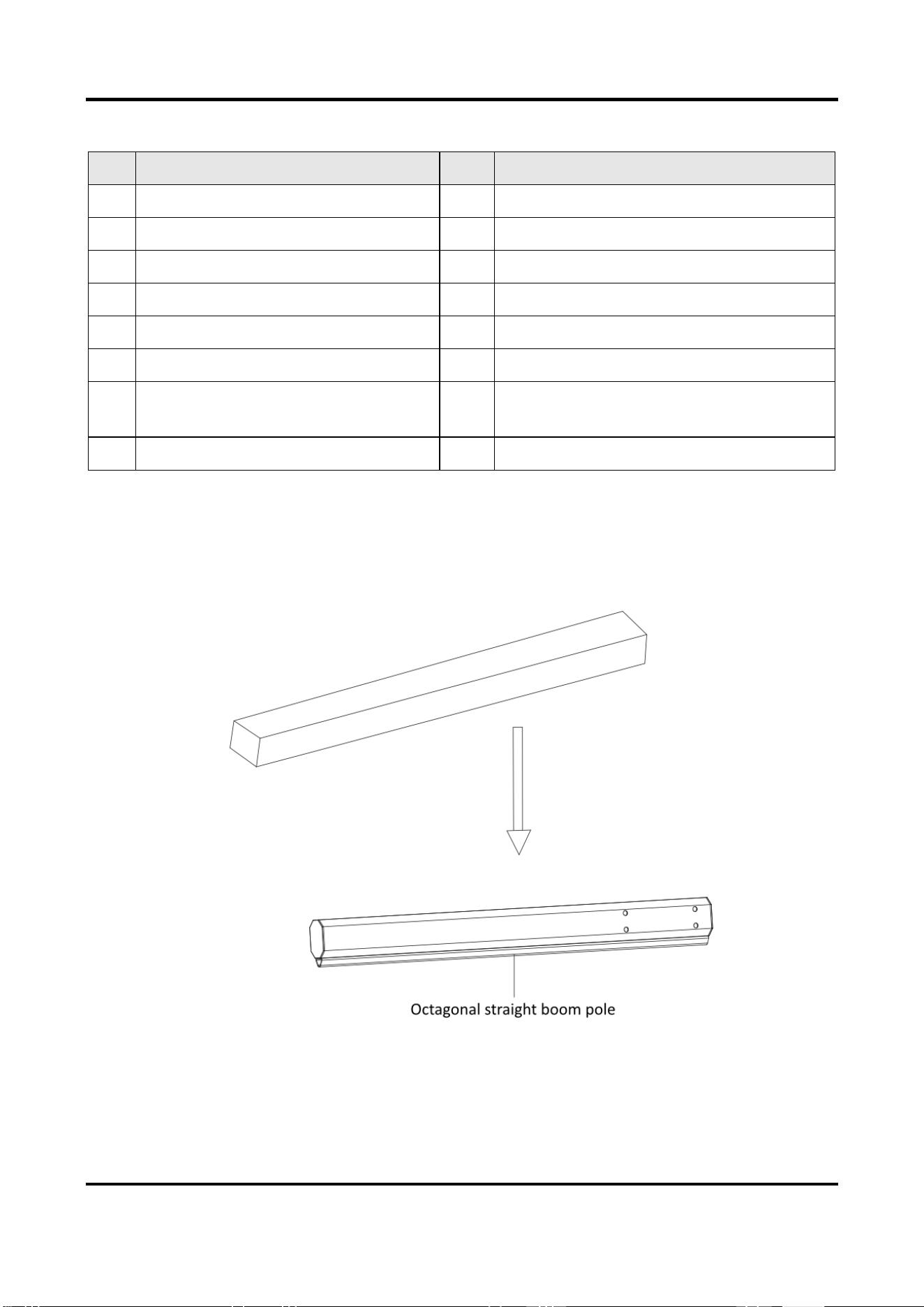
1.5.1 Octagonal Straight Boom Pole
Figure 1-3 Octagonal Straight Boom Pole

Barrier Gate User Manual
5
Table 1-3 Octagonal Straight Boom Pole Packing List
Item
Quantity
Octagonal Straight boom pole
1
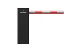
1.5.2 Boom Pole with Strip Light
Figure 1-4 Boom Pole with Strip Light
Table 1-4 Boom Pole with Strip Light Packing List
Item
Quantity
Boom pole with strip light
1
Cushion block
2

Barrier Gate User Manual
6
1.5.3 Anti-collision Cylinder Boom Pole
Figure 1-5 Anti-collision Cylinder Boom Pole
Table 1-5 Anti-collision Cylinder Boom Pole Packing List
Item
Quantity
Anti-collision cylinder boom pole
1
M8 cap nut
1
M8 × 75 hex socket head cap screw
1
Barrier Gate User Manual
7
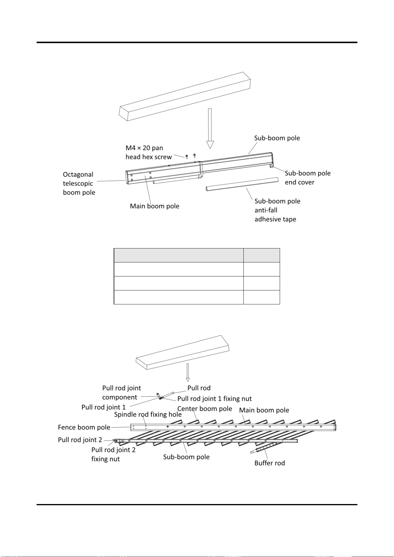
1.5.4 Octagonal Telescopic Boom Pole
Figure 1-6 Octagonal Telescopic Boom Pole
Table 1-6 Octagonal Telescopic Boom Pole Packing List
Item
Quantity
Octagonal telescopic boom pole
1
Sub-boom pole anti-fall adhesive tape
1
M4 × 20 pan head hex screw
2
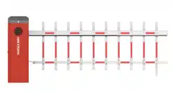
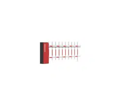
1.5.5 Fence Boom Pole
Figure 1-7 Fence Boom Pole

Barrier Gate User Manual
8
Table 1-7 Fence Boom Pole Packing List
Item
Quantity
Fence boom pole
1
Pull rod joint component
1
1.5.6 Folding Boom Pole
Figure 1-8 Folding Boom Pole
Table 1-8 Folding Boom Pole Packing List
Item
Quantity
Sub-boom pole
1
Main boom pole
1
Pull rod
1
Joint component to connect main boom pole and pull rod
1
Barrier Gate User Manual
9
Chapter 2 Installation
2.1 Installation Environment
The installation position of the barrier gate should meet the customer’s requirements and the
following requirements.
● The installation space should be large enough to guarantee the boom pole can rise or fall
normally.
● Install the barrier gate on horizontal ground.
● Installation surface requirements:
○ If no base is installed, the installation surface must be firm enough to fix the host to
guarantee the barrier gate can run stably.
○ If base is needed, it is recommended to install the base with quick setting cement. The base
should be horizontal. The height should be no more than 200 mm. The length and width of
base should be larger than those of the actual barrier gate installation surface.
● If the barrier gate is anti-collision, the boom pole will flick 90° in reverse direction if it is
impacted. Make sure there is no obstacle in the range.
● Bury the cables before installation. The conduit should be 50 mm higher than the ground to
avoid the gathered water on the ground to enter into the cable and cause short circuit.
2.2 Install Barrier Gate Host
Follow the steps below to fix the host of barrier gate.
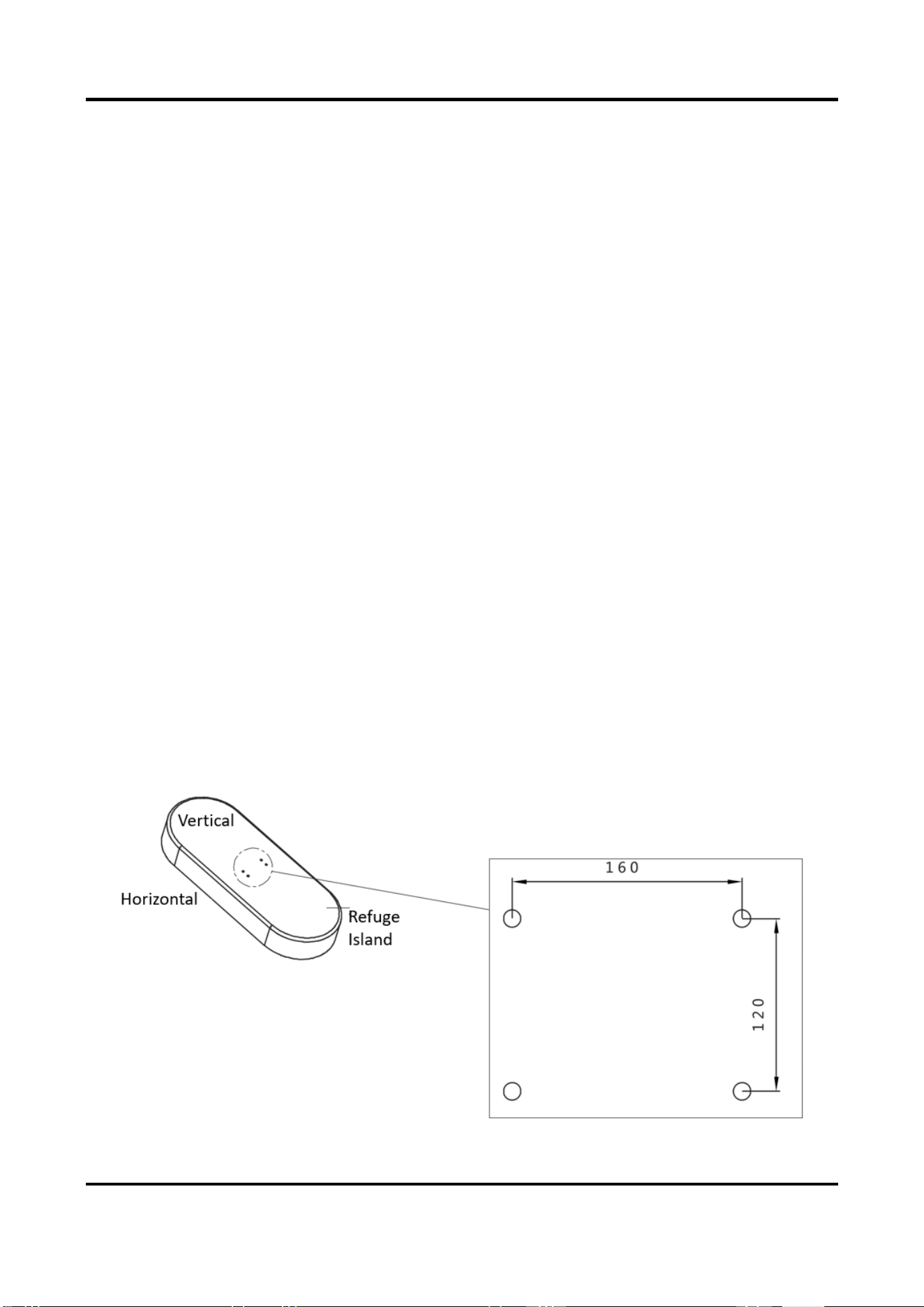
Steps
1. Mark the positions of holes on the refuge island as shown below. The hole depth is approx.
120 mm.
Barrier Gate User Manual
10
Figure 2-1 Mark Position
Note
The suggestions for positions of holes:
● The holes in vertical direction should be near to the switch.
● If the entrance/exit is unidirectional, the holes should be in the horizontal center of the
refuge island. If the entrance/exit is bi-directional, the holes in the horizontal direction should
be far away from the entrance/exit.
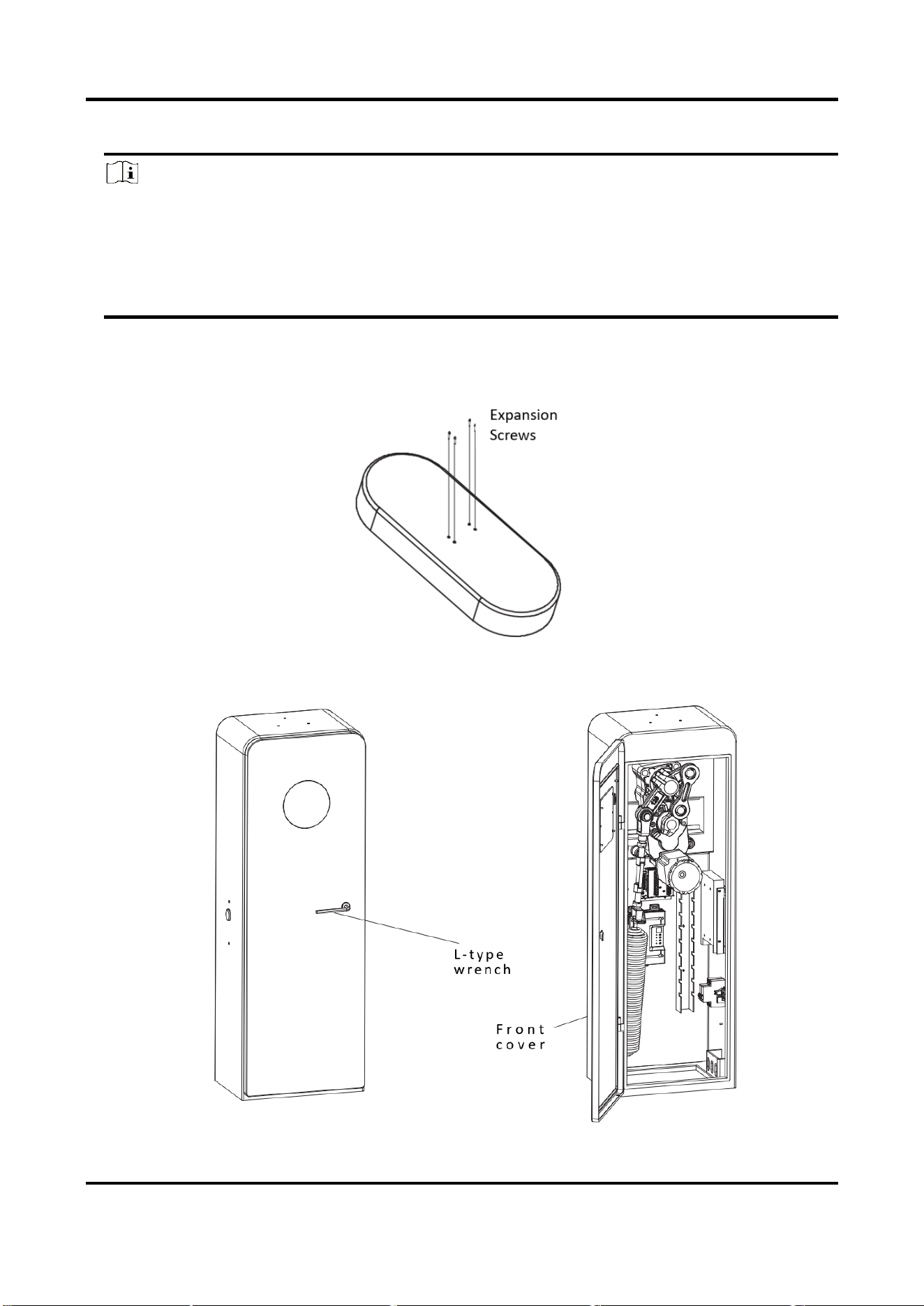
2. Punch the four M12 × 150 expansion screws in the package into the marked positions on the
refuge island, and fasten the nuts to make the screws expand to grip the ground. Then
unfasten the nuts.
Figure 2-2 Install Expansion Screws
3. Turn the L-type wrench clockwise to open the front cover.
Barrier Gate User Manual
11
Figure 2-3 Open Front Cover
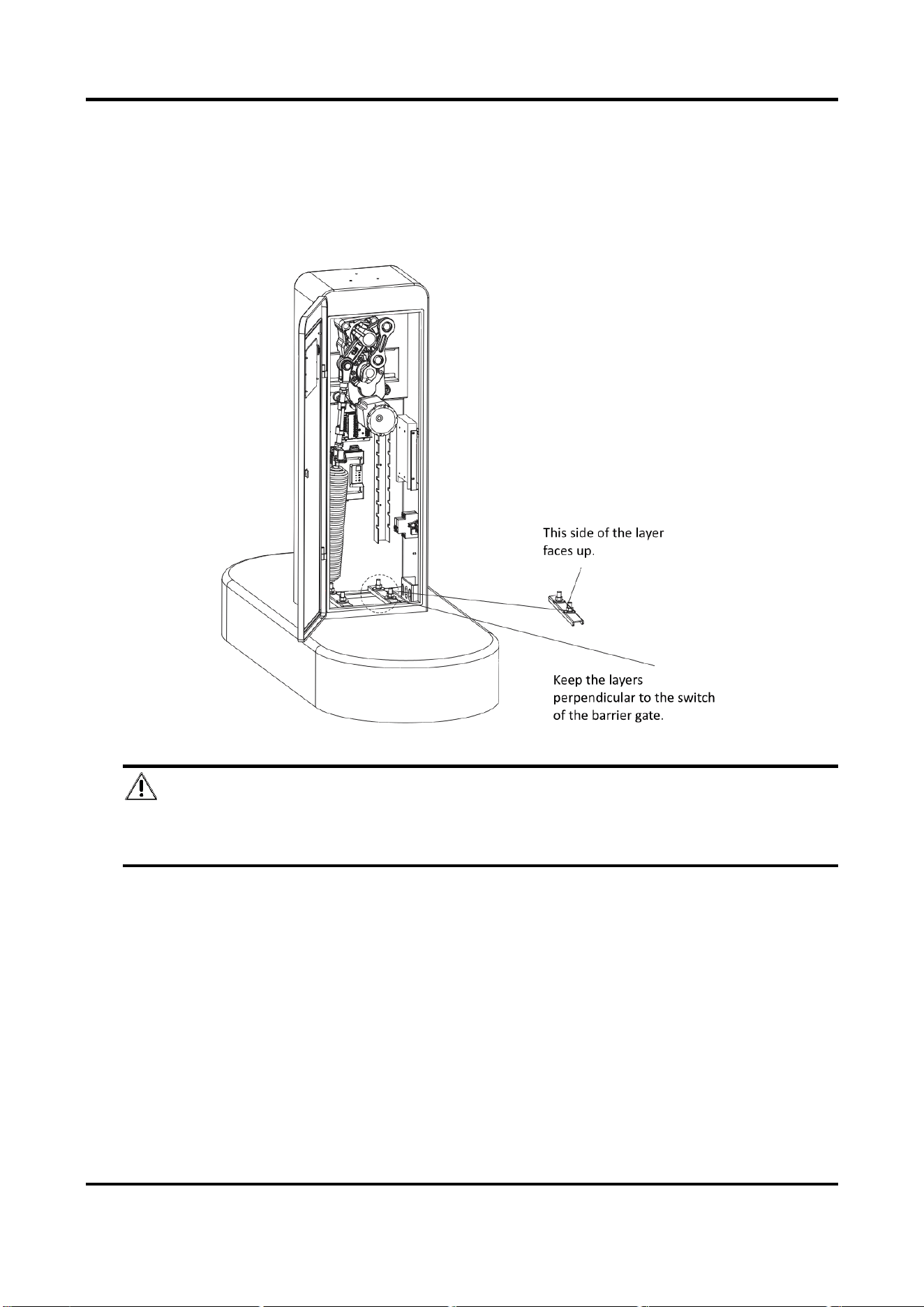
4. Fix the host.
1) Put the layers on the host bottom and keep them perpendicular to the barrier gate’s switch.
2) Put the host on the positions of expansion screws on the refuge island to make the screws
pass through the layers. Keep the layers perpendicular to the barrier gate’s switch.
3) Fasten the expansion nuts on the screws to fix the host.
Figure 2-4 Fix Host
Danger
Keep the supporting bracket of the boom pole vertically upward to avoid accident caused by
accidental rotation.
2.3 Install Boom Pole
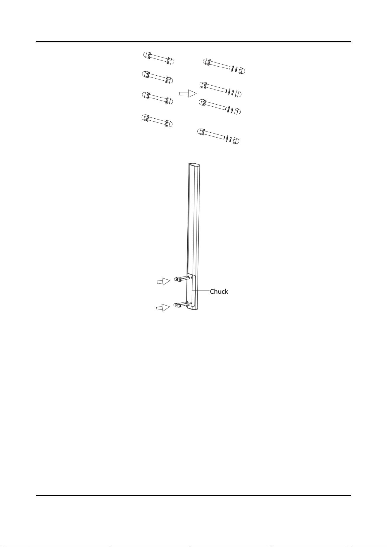
2.3.1 Install Octagonal Straight Boom Pole
Steps
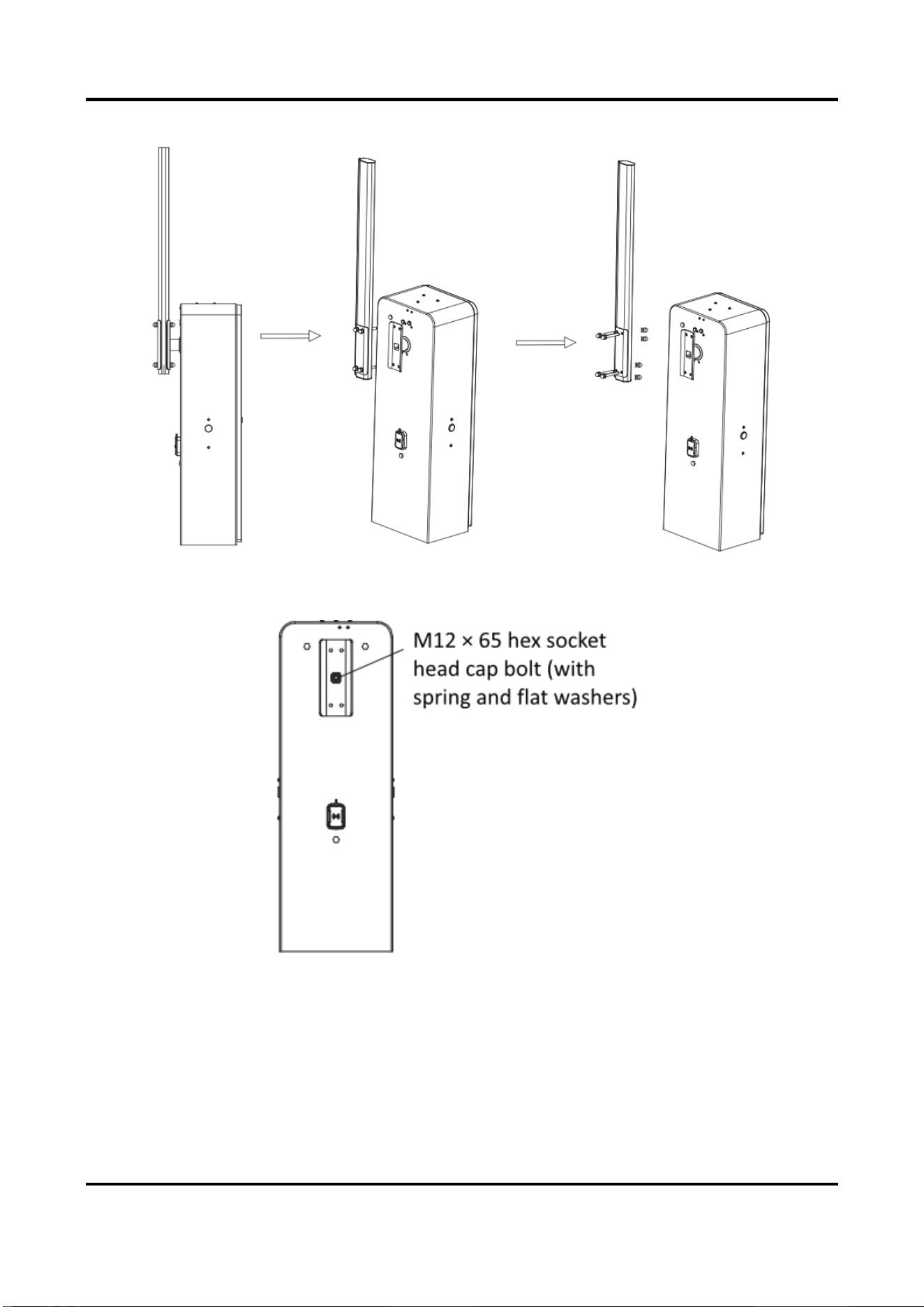
1. Unscrew the cap nuts, spring washers, and flat washers on the other sides of the four
assembling bolts. Save the components and parts for the following installations.
Barrier Gate User Manual
12
Figure 2-5 Unscrew Assembling Bolts
2. Install the chuck to the boom pole with the bolts as shown in the figure below.
Figure 2-6 Install Chuck
3. Install the boom pole to the spindle rod and fasten the other ends of the bolts with the
disassembled spring washers, flat washers, and cap nuts.
Barrier Gate User Manual
13
Figure 2-7 Fix Octagonal Straight Boom Pole
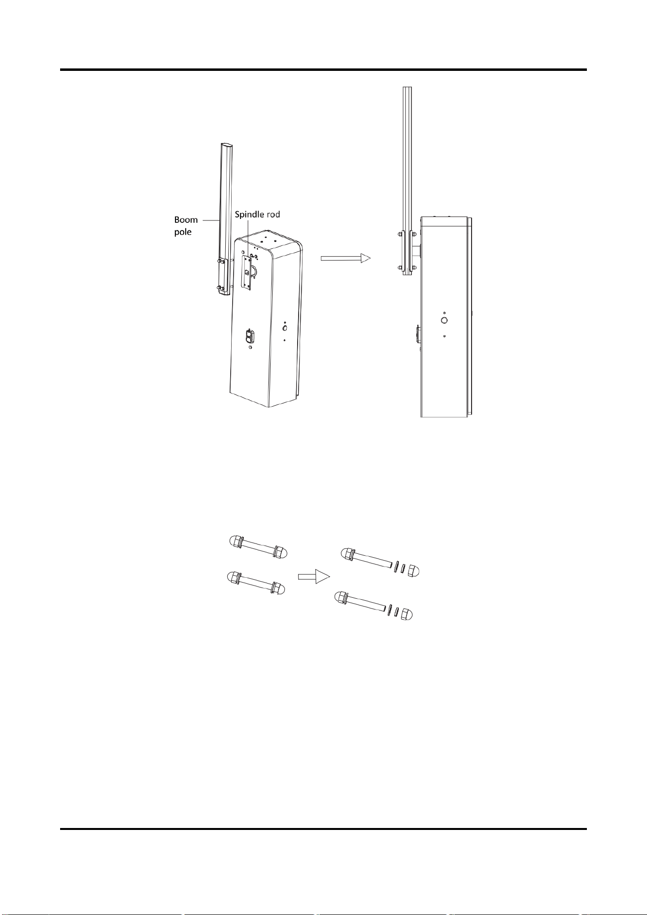
2.3.2 Install Boom Pole with Strip Light
Steps
1. Unscrew the cap nuts, spring washers, and flat washers on the other sides of the four
assembling bolts. Save the components and parts for the following installations.
Figure 2-8 Unscrew Assembling Bolts
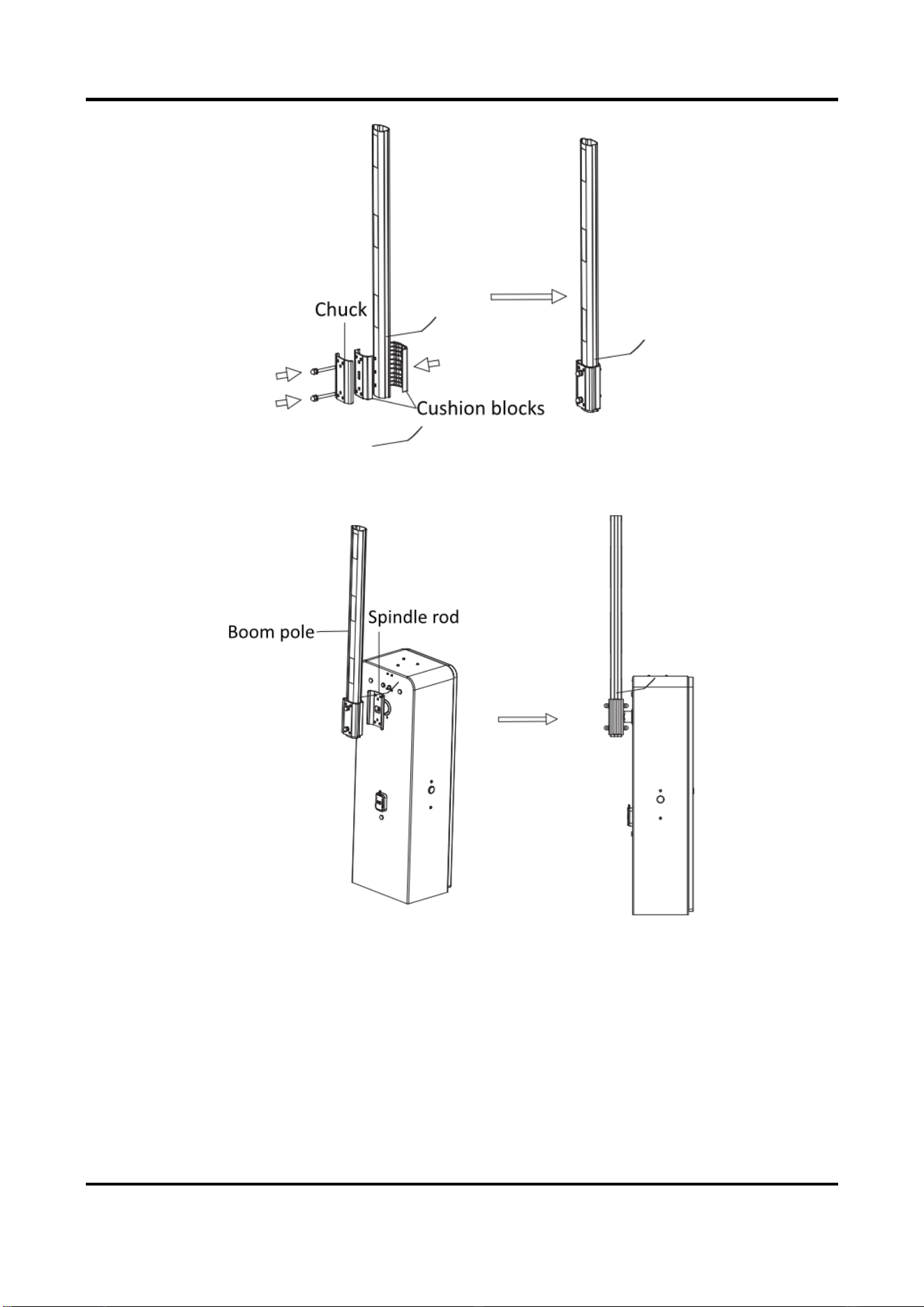
4. Install the chuck and two cushion blocks to the boom pole with the bolts as shown in the figure
below.
Barrier Gate User Manual
14
Figure 2-9 Install Chuck and Cushion Blocks
5. Install the boom pole to the spindle rod and fasten the other ends of the bolts with the
disassembled spring washers, flat washers, and cap nuts.
Figure 2-10 Fix Boom Pole with Strip Light
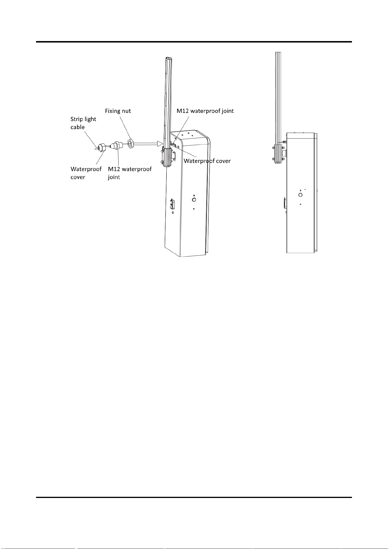
6. Remove the rubber plug of the cable hole on the host.

Barrier Gate User Manual
15
Figure 2-11 Remove Rubber Plug
7. Wire the strip light cable.
1) Take the M12 white waterproof joint out from the accessory package.
2) Fix the waterproof joint to the cable hole on the host with the fixing nut.
3) Remove the waterproof cover from the joint, and thread the strip light cable through the
waterproof cover, waterproof joint, and fixing nut.
4) Pull the strip light cable in the internal host until the white rolling strip limit block on the
strip light cable nears to the waterproof cover.
5) Power off the device. Rotate the boom pole to check if the strip light cable length is
appropriate. Fasten the waterproof cover to the joint after the length is appropriate.
Barrier Gate User Manual
16
Figure 2-12 Wire Strip Light Cable
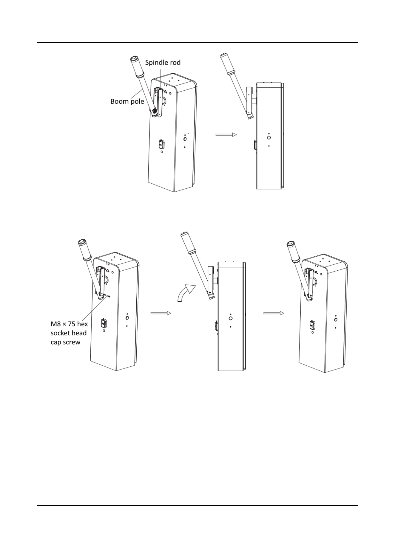
2.3.3 Install Anti-collision Cylinder Boom Pole
Steps
1. Stuff the boom pole in the spindle rod aslant as shown in the figure below. Align the
installation hole on the boom pole with that on the spindle rod.
Barrier Gate User Manual
17
Figure 2-13 Stuff Boom Pole Aslant
2. Insert the M8 × 75 hex socket head cap screw into the installation hole, and push the boom
pole into the spindle rod quickly according to the directions as shown in the figure below.
Figure 2-14 Install Anti-collision Cylinder Boom Pole
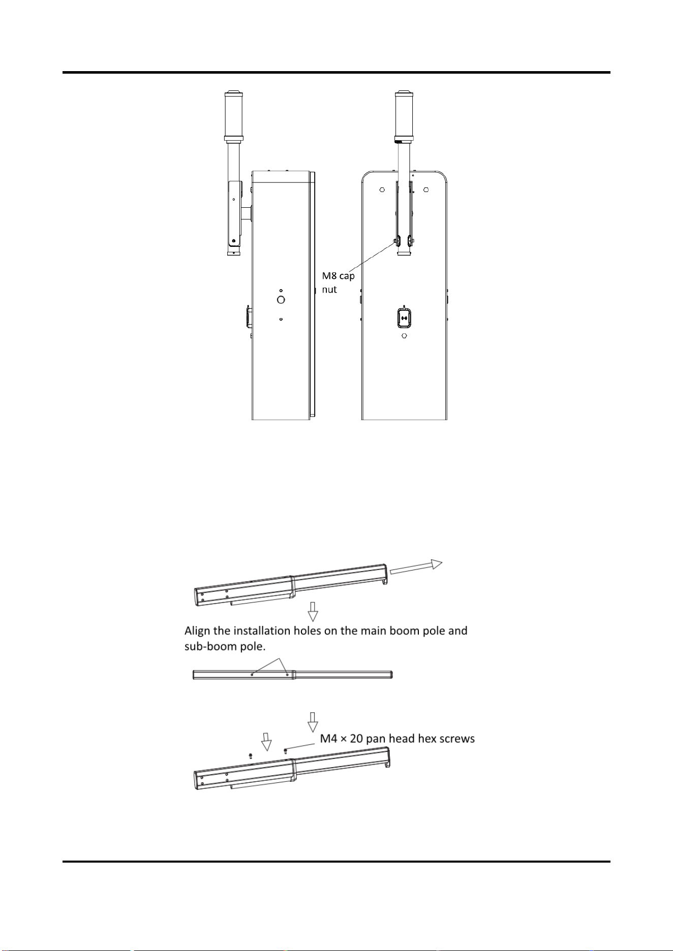
3. Fix the M8 cap nut to the screw to fix the boom pole.
Barrier Gate User Manual
18
Figure 2-15 Fix Boom Pole
2.3.4 Install Octagonal Telescopic Boom Pole
Steps
1. Install the octagonal telescopic boom pole.
1) Pull the sub-boom pole out according to the direction shown in the figure below. Align the
installation holes on the main boom pole and sub-boom pole.
Figure 2-16 Pull Sub-Boom Pole
2) Fix two M4 × 20 pan head hex screws into the installation holes.
Figure 2-17 Fix Screws
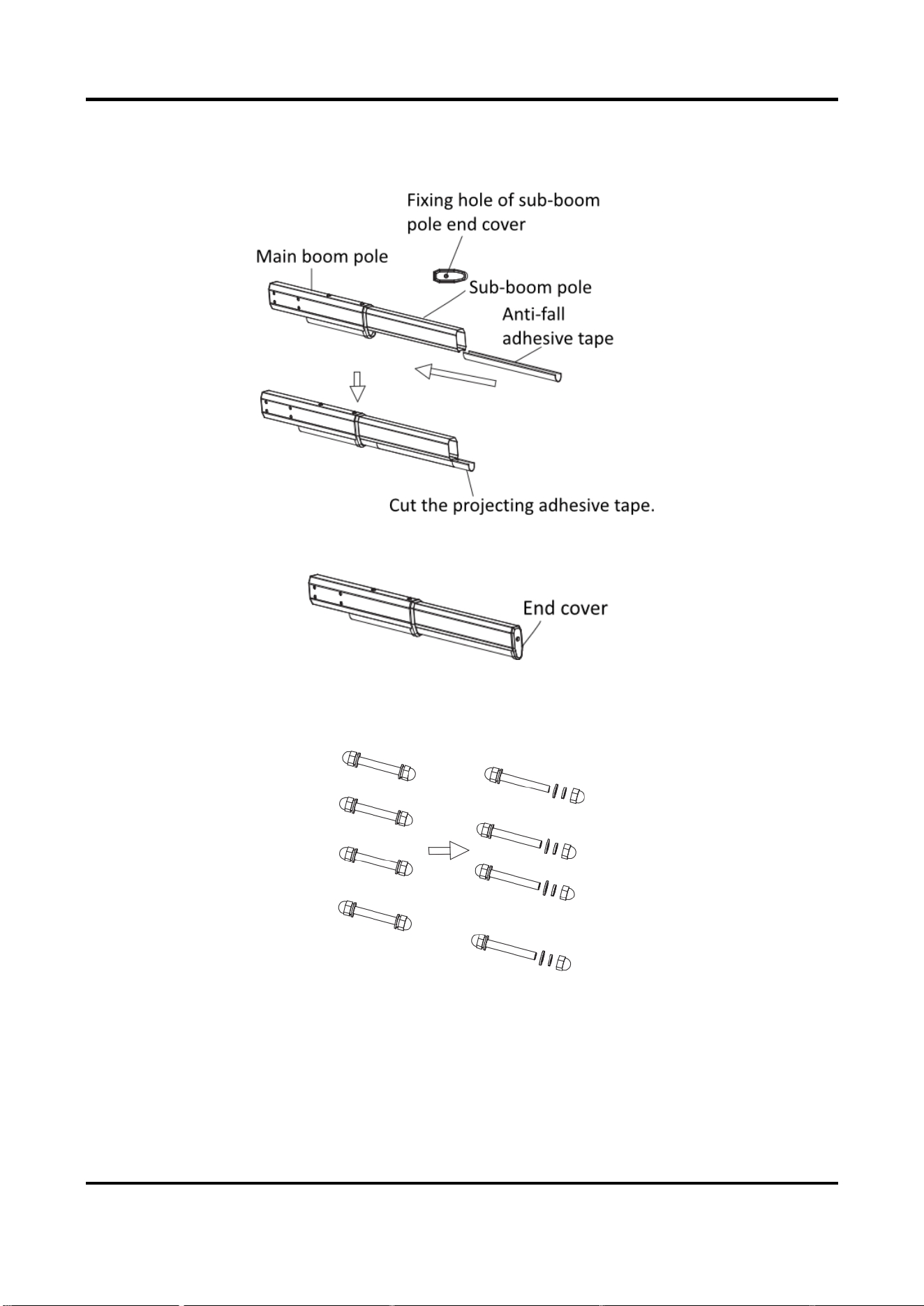
Barrier Gate User Manual
19
3) Remove the end cover of the sub-boom pole. Insert the anti-fall adhesive tape into the
sub-boom pole. After the anti-fall adhesive tape is inserted to the limit position, cut the
projecting adhesive tape.
Figure 2-18 Insert Anti-Fall Adhesive Tape
4) Install the end cover to the sub-boom pole.
Figure 2-19 Install End Cover
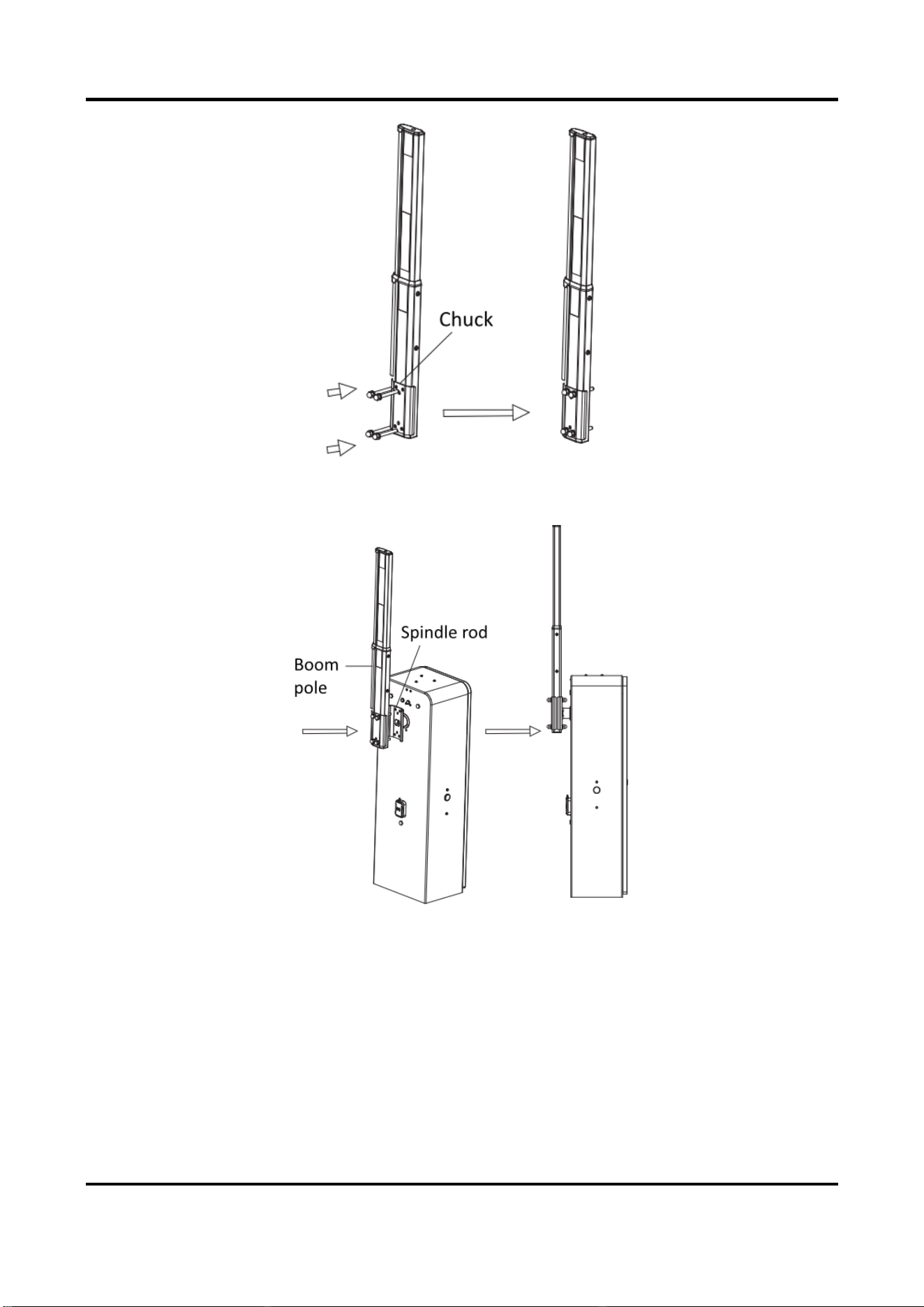
2. Install the octagonal telescopic boom pole to the host.
1) Unscrew the cap nuts, spring washers, and flat washers on the other sides of the four
assembling bolts. Save the components and parts for the following installations.
Figure 2-20 Unscrew Assembling Bolts
2) Install the chuck to the boom pole with the bolts as shown in the figure below.
Barrier Gate User Manual
20
Figure 2-21 Install Chuck
3) Install the boom pole to the spindle rod and fasten the other ends of the bolts with the
disassembled spring washers, flat washers, and cap nuts.
Figure 2-22 Fix Octagonal Telescopic Boom Pole
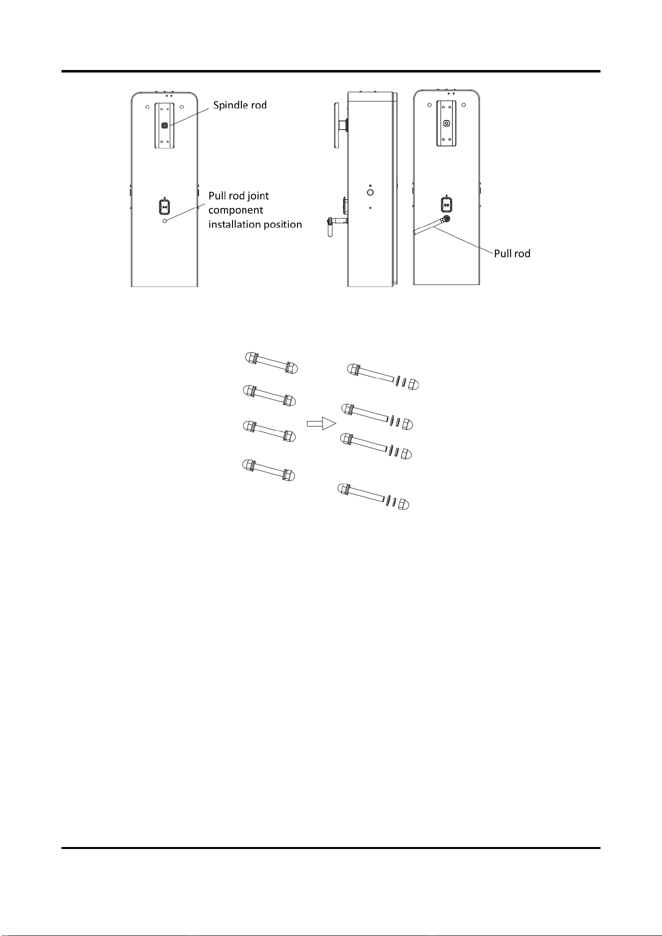
2.3.5 Install Fence Boom Pole
Installation Procedure
Steps
1. Install the pull rod joint component to the installation position of the host. Unfasten the joint
component pull rod.
Barrier Gate User Manual
21
Figure 2-23 Install Pull Rod Joint Component
2. Install the fence boom pole.
1) Unscrew the cap nuts, spring washers, and flat washers on the other sides of the four
assembling bolts. Save the components and parts for the following installations.
Figure 2-24 Unscrew Assembling Bolts
2) Install the chuck to the boom pole with the bolts as shown in the figure below.
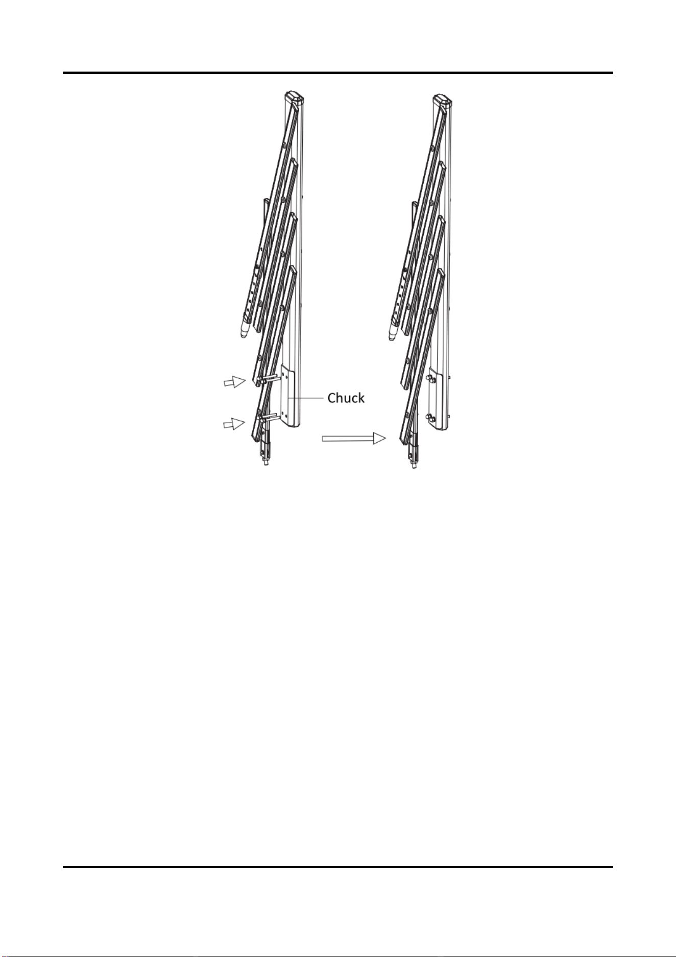
Barrier Gate User Manual
22
Figure 2-25 Install Chuck
3) Install the boom pole to the spindle rod and fasten the other ends of the bolts with the
disassembled spring washers, flat washers, and cap nuts.

Barrier Gate User Manual
23
Figure 2-26 Fix Fence Boom Pole to Spindle Rod
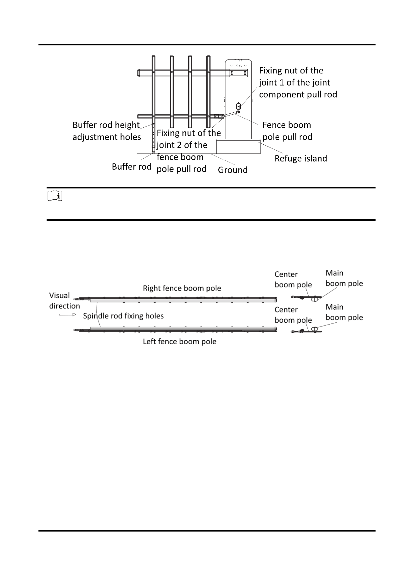
4) Power off the device. Pull the fence boom pole to the horizontal position. Connect the pull
rod of the joint component to the joint 2 of the fence boom pole pull rod. Wrest the pull
rod of the joint component until the center boom poles are in the vertical position. Fasten
the fixing nuts of the joint 1 of the joint component pull rod and joint 2 of the fence boom
pole pull rod respectively.
5) Adjust the buffer rod height adjustment holes on the fence boom pole until the end of the
buffer rod is on the same horizontal surface with that of the refuge island.
Barrier Gate User Manual
24
Figure 2-27 Adjust Fence Boom Pole
Note
For the refuge island with a special height, drill holes by yourself to adjust the buffer rod height.
Left and Right Directions of Fence Boom Pole
When you look from the arrow direction as shown below, the right fence boom pole is the one
that the center boom poles are on the left of the main boom pole, and the left fence boom pole is
the one that the center boom poles are on the right of the main boom pole.
Figure 2-28 Left and Right Directions of Fence Boom Pole
2.3.6 Install Folding Boom Pole
Steps
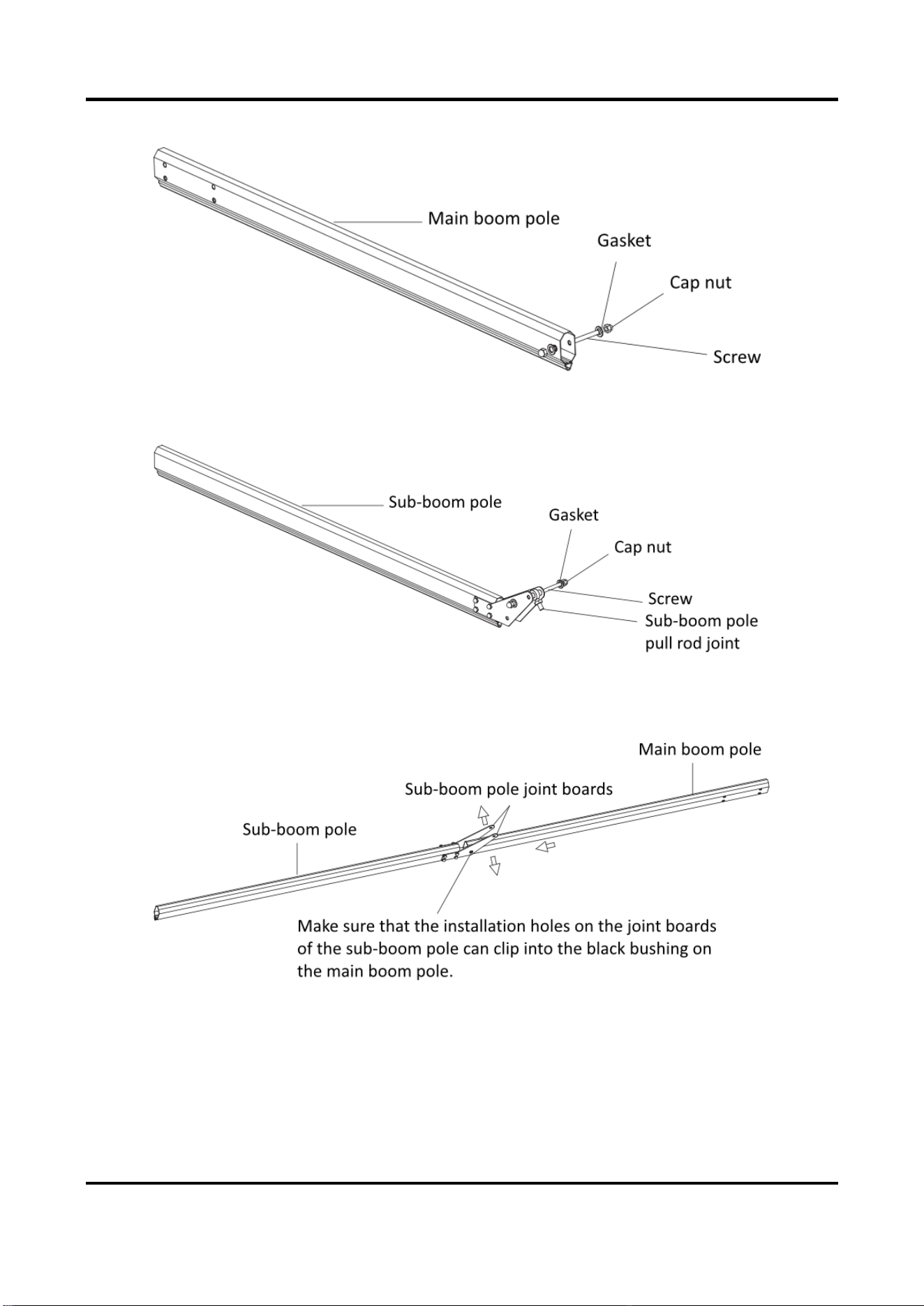
1. Compose the main boom pole and sub-boom pole.
1) Unfasten the cap nuts on the main boom pole and remove the screw and gaskets. Save the
Barrier Gate User Manual
25
components and parts for the following installations.
Figure 2-29 Unfasten Accessories of Main Boom Pole
2) Unfasten the cap nuts on the sub-boom pole and remove the screw, gaskets, and sub-
boom pole pull rod joint. Save the components and parts for the following installations.
Figure 2-30 Unfasten Accessories of Sub- Boom Pole
3) Force apart the sub-boom pole joint boards, and install the main boom pole. Make sure
that the installation holes on the joint boards of the sub-boom pole can clip into the black
bushing on the main boom pole.
Figure 2-31 Connect Main Boom Pole and Sub-Boom Pole
4) Put the sub-boom pole pull rod joint between the joint boards, and insert the screw
through the pull rod joint and gaskets, and fasten the cap nuts. Insert the other screw
through the other installation holes on the sub-boom pole joint boards and gaskets, and
fasten the cap nuts. Make sure that the black bushing on the sub-boom pole pull rod joint

Barrier Gate User Manual
26
can clip into installation holes on the sub-boom pole joint boards.
Figure 2-32 Install Sub-Boom Pole Pull Rod Joint
2. Install the folding boom pole to the host.
Note
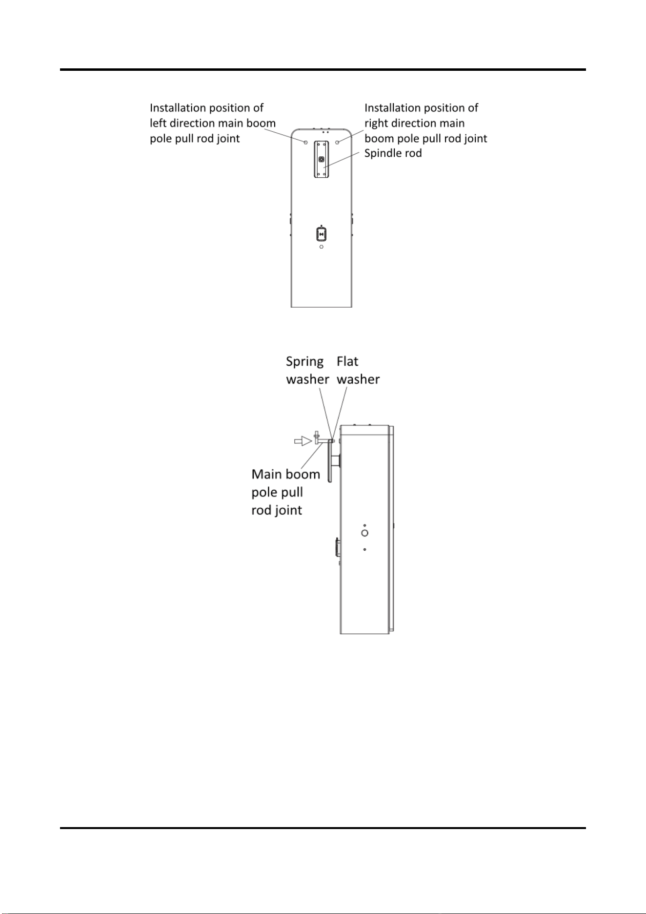
Here we take example of the right direction barrier gate.
1) Remove the plastic nut on the installation position of the right direction main boom pole pull
Barrier Gate User Manual
27
rod joint.
Figure 2-33 Remove Plastic Nut
2) Install the right direction main boom pole pull rod joint to the installation holes with the flat
washer and spring washer.
Figure 2-34 Install Main Boom Pole Pull Rod Joint
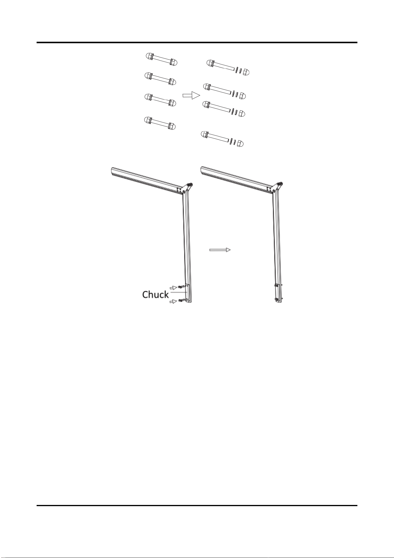
3) Unscrew the cap nuts, spring washers, and flat washers on the other sides of the four
assembling bolts. Save the components and parts for the following installations.
Barrier Gate User Manual
28
Figure 2-35 Unscrew Assembling Bolts
4) Install the chuck to the boom pole with the bolts as shown in the figure below.
Figure 2-36 Install Chuck
5) Install the boom pole to the spindle rod and fasten the other ends of the bolts with the
disassembled spring washers, flat washers, and cap nuts.

Barrier Gate User Manual
29
Figure 2-37 Fix Folding Boom Pole
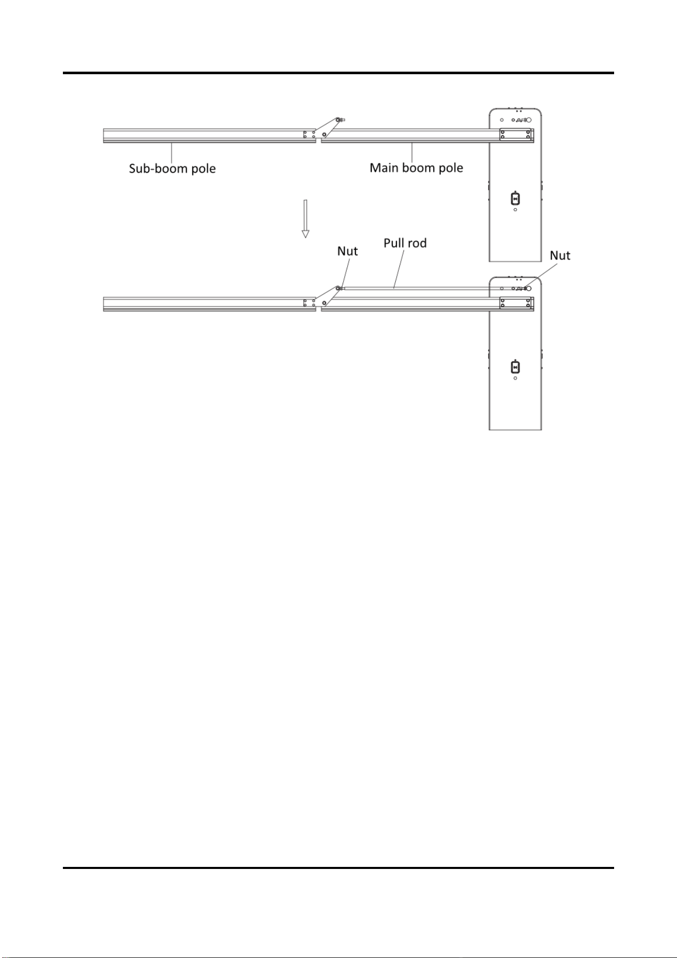
6) Power off the device. Pull the main boom pole to the horizontal position, and place the sub-
boom pole nearly to the horizontal position. Wrest the pull rod between the sub-boom pole
pull rod joint and the main boom pole pull rod joint. Wrest the pull rod continuously to keep
the main boom pole and sub-boom pole in the horizontal position, and fasten the nuts on
Barrier Gate User Manual
30
both ends.
Figure 2-38 Connect Boom Pole to Host via Pull Rod
2.4 Wiring
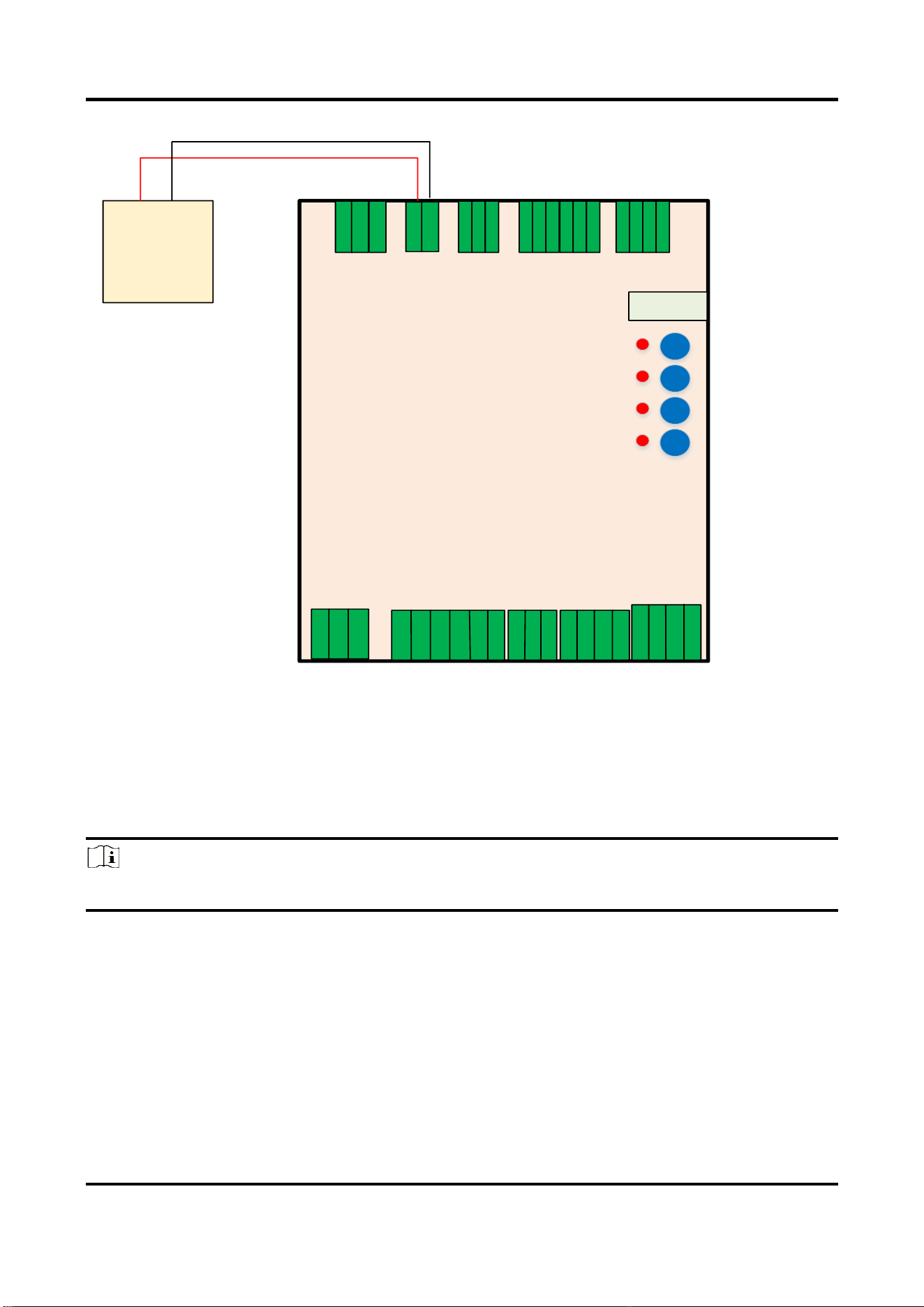
2.4.1 Connect to Power Supply
Connect the barrier gate to the power supply according to the figure shown below.
Barrier Gate User Manual
31
Barrier Gate
Remote Controller
Nixie Tube
Power
Adapter
24 V
GND
24 V +
24 V -
UPS+
DET
UPS-
24V
U
V
W
GND
GND
Hu
Hv
Hw
NC
5V
GND
485-
485+
5V
Capacitor
Board
Power
Interface
Motor Line
Motor Hall
Sensor
Remote
Controller
Red Light
COM
Green Light
Rising
Control +
Rising
Control -
Falling
Control +
Falling
Control-
Stopping
Control+
Stopping
Control-
RS485+
RS485-
GND
12V
GND
Induction
-
Induction
+
Falling Limit
+
Falling Limit
-
Rising Limit
+
Rising Limit
-
Inductive Input
Interface
Red/Green Light
Rising/Falling/
Stopping Control
Limit Output
RS485
Rise
Stop
Fall
Learn
Figure 2-39 Connect to Power Supply
2.4.2 Connect to Supercapacitor Board
Connect the barrier gate to the supercapacitor board as the figure shown below to realize that the
boom pole can rise automatically to let the vehicles pass when the power supply is cut off.
Note
The supercapacitor board needs to be ordered in addition.

Barrier Gate User Manual
32
Supercapacitor
Board
(Ordered in
Addition)
UPS+
UPS-
DET
UPS+
DET
UPS-
Barrier Gate
Remote Controller
Nixie Tube
UPS+
DET
UPS-
24V
U
V
W
GND
GND
Hu
Hv
Hw
NC
5V
GND
485-
485+
5V
Capacitor
Board
Power
Interface
Motor Line
Motor Hall
Sensor
Remote
Controller
Rise
Stop
Fall
Learn
Red Light
COM
Green Light
Rising
Control +
Rising
Control -
Falling
Control +
Falling
Control-
Stopping
Control+
Stopping
Control-
RS485+
RS485-
GND
12V
GND
Induction
-
Induction
+
Falling Limit
+
Falling Limit
-
Rising Limit
+
Rising Limit
-
Inductive Input
Interface
Red/Green Light
Rising/Falling/
Stopping Control
Limit Output
RS485
Figure 2-40 Connect to Supercapacitor Board
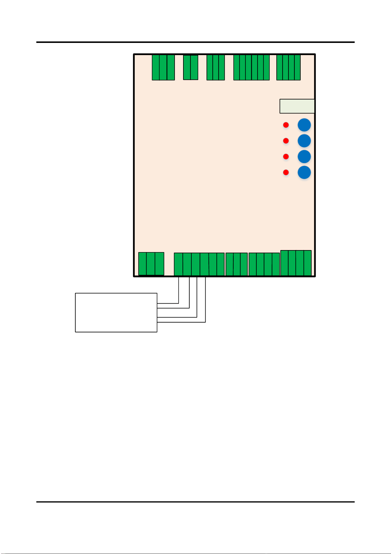
2.4.3 Connect to Access ANPR Camera
As the figure shown below, connect the rising control + and rising control – interfaces of the
barrier gate to the rising control interfaces of the access ANPR camera, and connect the falling
control + and falling control – interfaces of the barrier gate to the falling control interfaces of the
access ANPR camera.
Barrier Gate User Manual
33
1A
1B
2A
2B
Rising
Control
Falling
Control
Barrier Gate
Remote Controller
Nixie Tube
Rise
Stop
Fall
Learn
Access ANPR
Camera
Red Light
COM
Green Light
Rising
Control +
Rising
Control -
Falling
Control +
Falling
Control-
Stopping
Control+
Stopping
Control-
RS485+
RS485-
GND
12V
GND
Induction
-
Induction
+
Falling Limit
+
Falling Limit
-
Rising Limit
+
Rising Limit
-
Inductive
Input Interface
Red/Green
Light
Rising/Falling/
Stopping Control
Limit Output
RS485
UPS+
DET
UPS-
24V
U
V
W
GND
GND
Hu
Hv
Hw
NC
5 V
GND
485-
485+
5 V
Capacitor
Board
Power
Interface
Motor Line
Motor Hall
Sensor
Remote
Controller
Figure 2-41 Connect to Access ANPR Camera
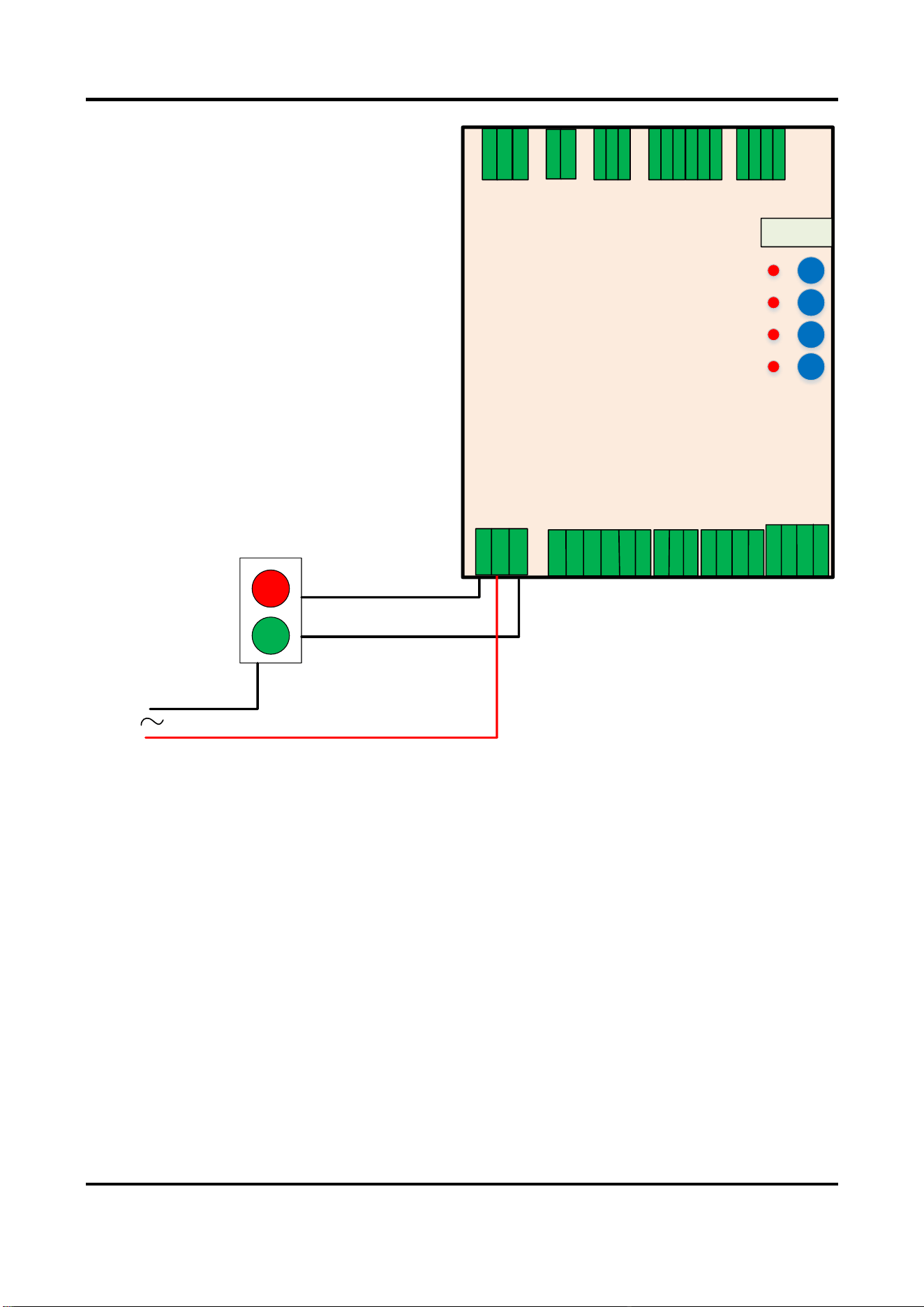
2.4.4 Connect to Traffic Signal Light
Connect the live line to the COM interface of the barrier gate. Connect the red light interface of
the barrier gate to the red traffic signal light, and connect the green light interface of the barrier
gate to the green traffic signal light. Connect the null line to the red and green traffic signal lights.
Barrier Gate User Manual
34
Live Line
Null Line
Connect to Red Light
Connect to Green Light
Incoming
Live Line
Barrier Gate
Remote Controller
Nixie Tube
Rise
Stop
Fall
Learn
UPS+
DET
UPS-
24V
U
V
W
GND
GND
Hu
Hv
Hw
NC
5 V
GND
485-
485+
5 V
Capacitor
Board
Power
Interface
Motor Line
Motor Hall
Sensor
Remote
Controller
Red Light
COM
Green Light
Rising
Control +
Rising
Control -
Falling
Control +
Falling
Control-
Stopping
Control+
Stopping
Control-
RS485+
RS485-
GND
12V
GND
Induction
-
Induction
+
Falling Limit
+
Falling Limit
-
Rising Limit
+
Rising Limit
-
Inductive Input
Interface
Red/Green Light
Rising/Falling/
Stopping Control
Limit Output
RS485
Figure 2-42 Connect to Traffic Signal Light
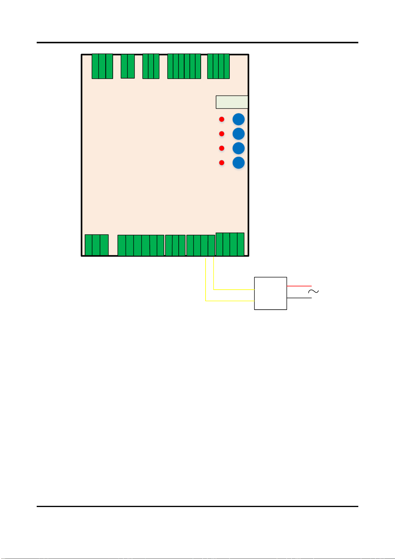
2.4.5 Connect to Anti-fall Radar
Anti-fall Radar Wiring
The anti-fall radar needs to be powered by 12 VDC power supply. Connect the 12 VDC interface
and GND interface of the barrier gate to the radar.

Barrier Gate User Manual
35
Radar Red Line
Radar Black Line
Barrier Gate
Remote Controller
Nixie Tube
Anti-fall
Radar
Red Light
COM
Green Light
Rising
Control +
Rising
Control -
Falling
Control +
Falling
Control-
Stopping
Control+
Stopping
Control+
RS485+
RS485-
GND
12V
GND
Induction
-
Induction
+
Falling Limit
+
Falling Limit
-
Rising Limit
+
Rising Limit
-
Inductive Input
Interface
Red/Green Light
Rising/Falling/
Stopping Control
Limit Output
RS485
Rise
Stop
Fall
Learn
UPS+
DET
UPS-
24V
U
V
W
GND
GND
Hu
Hv
Hw
NC
5V
GND
485-
485+
5V
Capacitor
Board
Power
Interface
Motor Line
Motor Hall
Sensor
Remote
Controller
Figure 2-43 Connect to Anti-fall Radar
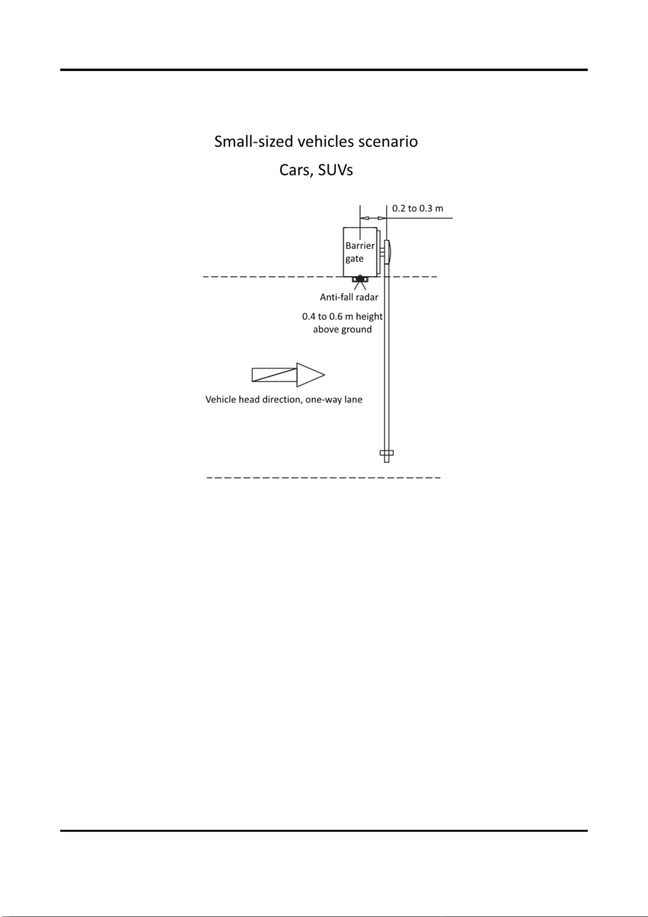
Radar Installation Instructions
The anti-fall radar should be installed beside the barrier gate. In different scenarios, follow the
instructions below to get the best effect.
Barrier Gate User Manual
36
Scenario 1: Small-Sized Vehicles
For small-sized vehicles, such as the cars and SUVs, install the radar according to the figure shown
below.
Figure 2-44 Small-Sized Vehicles Scenario
Scenario 2: Large-Sized Vehicles
For large-sized vehicles, such as the oil tank trucks, transport vehicles, trucks, and other vehicles
with chassises of higher than 1 m, install the radar according to the figure shown below.

Barrier Gate User Manual
37
Figure 2-45 Large-Sized Vehicles Scenario
Scenario 3: Mixed Traffic
For mixed traffic scenario, such as the large-sized and small-sized vehicles are mixing, install the
radar according to the figure shown below.

Barrier Gate User Manual
38
Figure 2-46 Mixed Traffic Scenario
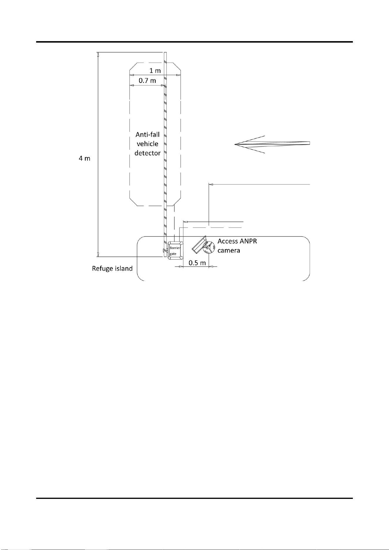
2.4.6 Connect to Vehicle Detector
Vehicle Detector Wiring
Connect the Induction+ and Induction- interfaces of the barrier gate to the vehicle detector.
Barrier Gate User Manual
39
Vehicle
Detector
Anti-fall vehicle
detector
Live Line
Null Line
Barrier Gate
Remote Controller
Nixie Tube
Rise
Stop
Fall
Learn
Anti-fall vehicle
detector
Red Light
COM
Green Light
Rising
Control +
Rising
Control -
Falling
Control +
Falling
Control-
Stopping
Control+
Stopping
Control+
RS485+
RS485-
GND
12V
GND
Induction
-
Induction
+
Falling Limit
+
Falling Limit
-
Rising Limit
+
Rising Limit
-
Inductive Input
Interface
Red/Green Light
Rising/Falling/
Stopping Control
Limit Output
RS485
UPS+
DET
UPS-
24V
U
V
W
GND
GND
Hu
Hv
Hw
NC
5V
GND
485-
485+
5V
Capacitor
Board
Power
Interface
Motor Line
Motor Hall
Sensor
Remote
Controller
Figure 2-47 Connect to Vehicle Detector
Vehicle Detector Installation Instructions
The general width of the vehicle detector is 1 m. If there are large-sized vehicles passing in the
scenario, widen the width to 1.5 m.
The anti-fall vehicle detector should be installed behind the barrier gate to avoid that the boom
pole falls down and smashes the vehicle after the vehicle passes the vehicle detector and the
signal disappears.
Barrier Gate User Manual
40
Figure 2-48 Vehicle Detector Installation
2.4.7 Connect to Active Infrared Intrusion Detector
Connect the Induction+ interface of the barrier gate to the COM interface of the active infrared
intrusion detector, and the Induction- interface of the barrier gate to the OUT interface of the
active infrared intrusion detector.

Barrier Gate User Manual
41
Barrier Gate
Remote Controller
Nixie Tube
Open
Stop
Close
Learn
COM OUT
UPS+
DET
UPS-
24V
U
V
W
GND
GND
Hu
Hv
Hw
NC
5V
GND
485-
485+
5V
Capacitor
Board
Power
Interface
Motor Line
Motor Hall
Sensor
Remote
Controller
Red Light
COM
Green Light
Rising
Control +
Rising
Control -
Falling
Control +
Falling
Control-
Stopping
Control+
Stopping
Control+
RS485+
RS485-
GND
12V
GND
Induction
-
Induction
+
Falling Limit
+
Falling Limit
-
Rising Limit
+
Rising Limit
-
Inductive Input
Interface
Red/Green Light
Rising/Falling/
Stopping Control
Limit Output
RS485
Figure 2-49
Connect to Active Infrared Intrusion Detector
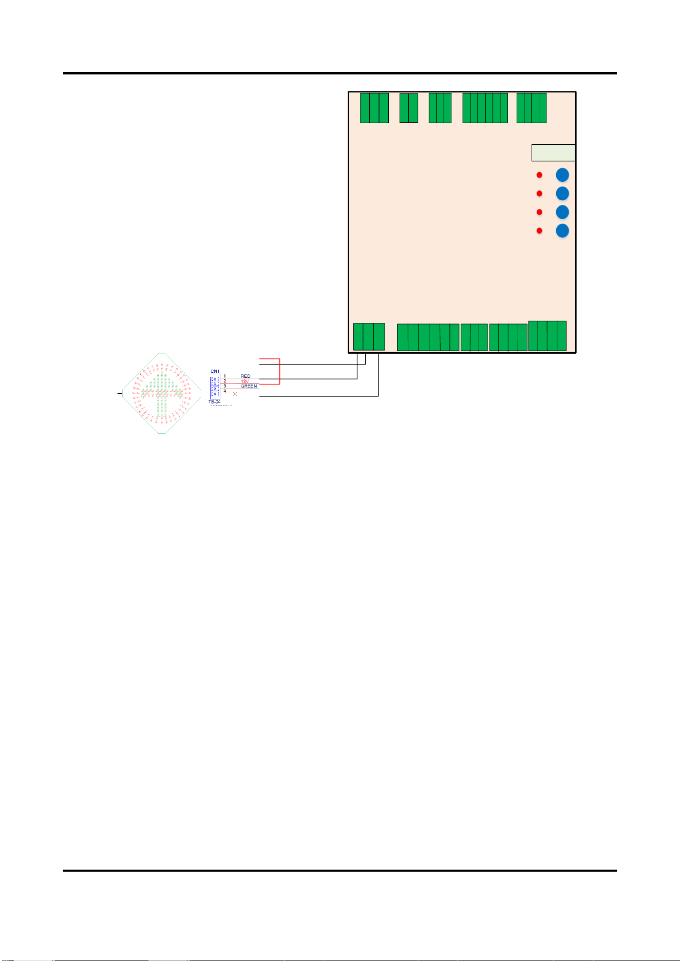
2.4.8 Connect to Arrow Indicator
Connect the arrow indicator to the barrier gate as shown below.
Barrier Gate User Manual
42
12V
GND
Barrier Gate
Remote Controller
Nixie Tube
Rise
Stop
Close
Learn
Fro
nt
Red Light
COM
Green Light
Rising Control
+
Rising Control
-
Falling Control
+
Falling Control
-
Stopping
Control+
Stopping
Control-
RS485+
RS485-
GND
12V
GND
Induction
-
Induction
+
Falling Limit
+
Falling Limit
-
Rising Limit
+
Rising Limit
-
Inductive Input Interface
Red/Green Light
Rising/Falling/
Stopping Control
Limit Output
RS485
UPS+
DET
UPS-
24V
U
V
W
GND
GND
Hu
Hv
Hw
NC
5 V
GND
485-
485+
5 V
Capacitor
Board
Power InterfaceMotor Line Motor Hall Sensor Remote Controller
Figure 2-50 Connect to Arrow Indicator
2.4.9 Connect to Strip Light
For the boom pole with strip light, connect the strip light to the barrier gate as shown below.
Barrier Gate User Manual
43
Strip Light
Strip Light Wire (Yellow)
Strip Light Wire (Green)
Strip Light Wire (Red)
12V
GND
Barrier Gate
Remote Controller
Nixie Tube
Rise
Stop
Fall
Learn
UPS+
DET
UPS-
24V
U
V
W
GND
GND
Hu
Hv
Hw
NC
5 V
GND
485-
485+
5 V
Capacitor
Board
Power
Interface
Motor Line
Motor Hall
Sensor
Remote
Controller
Red Light
COM
Green Light
Rising
Control +
Rising
Control -
Falling
Control +
Falling
Control-
Stopping
Control+
Stopping
Control+
RS485+
RS485-
GND
12V
GND
Induction
-
Induction
+
Falling Limit
+
Falling Limit
-
Rising Limit
+
Rising Limit
-
Inductive Input
Interface
Red/Green Light
Rising/Falling/
Stopping Control
Limit Output
RS485
Figure 2-51 Connect to Strip Light
2.4.10 Connect to Warning Light
For the barrier gate with a warning light on the top of host, connect the warning light to the
barrier gate as shown below.

Barrier Gate User Manual
44
Warning Light Wire (Red)
Warning Light Wire (Black)
12 V
GND
Barrier Gate
Remote Controller
Nixie Tube
Rise
Stop
Fall
Learn
Red Light
COM
Green Light
Rising
Control +
Rising
Control -
Falling
Control +
Falling
Control-
Stopping
Control+
Stopping
Control+
RS485+
RS485-
GND
12V
GND
Induction
-
Induction
+
Falling Limit
+
Falling Limit
-
Rising Limit
+
Rising Limit
-
Inductive Input
Interface
Red/Green Light
Rising/Falling/
Stopping Control
Limit Output
RS485
UPS+
DET
UPS-
24V
U
V
W
GND
GND
Hu
Hv
Hw
NC
5V
GND
485-
485+
5V
Capacitor
Board
Power
Interface
Motor Line
Motor Hall
Sensor
Remote
Controller
Figure 2-52 Connect to Warning Light
Barrier Gate User Manual
45
Chapter 3 Parameters Configuration
After the installation completes, power on the barrier gate, and it will operate self-check of rising
to limit position. After the self-check completes, you can control the barrier gate via remote
controller or buttons.
3.1 Remote Control
After the self-check completes, you can control the boom pole to rise, fall, and stop via the remote
controller leaving factory with the barrier gate.
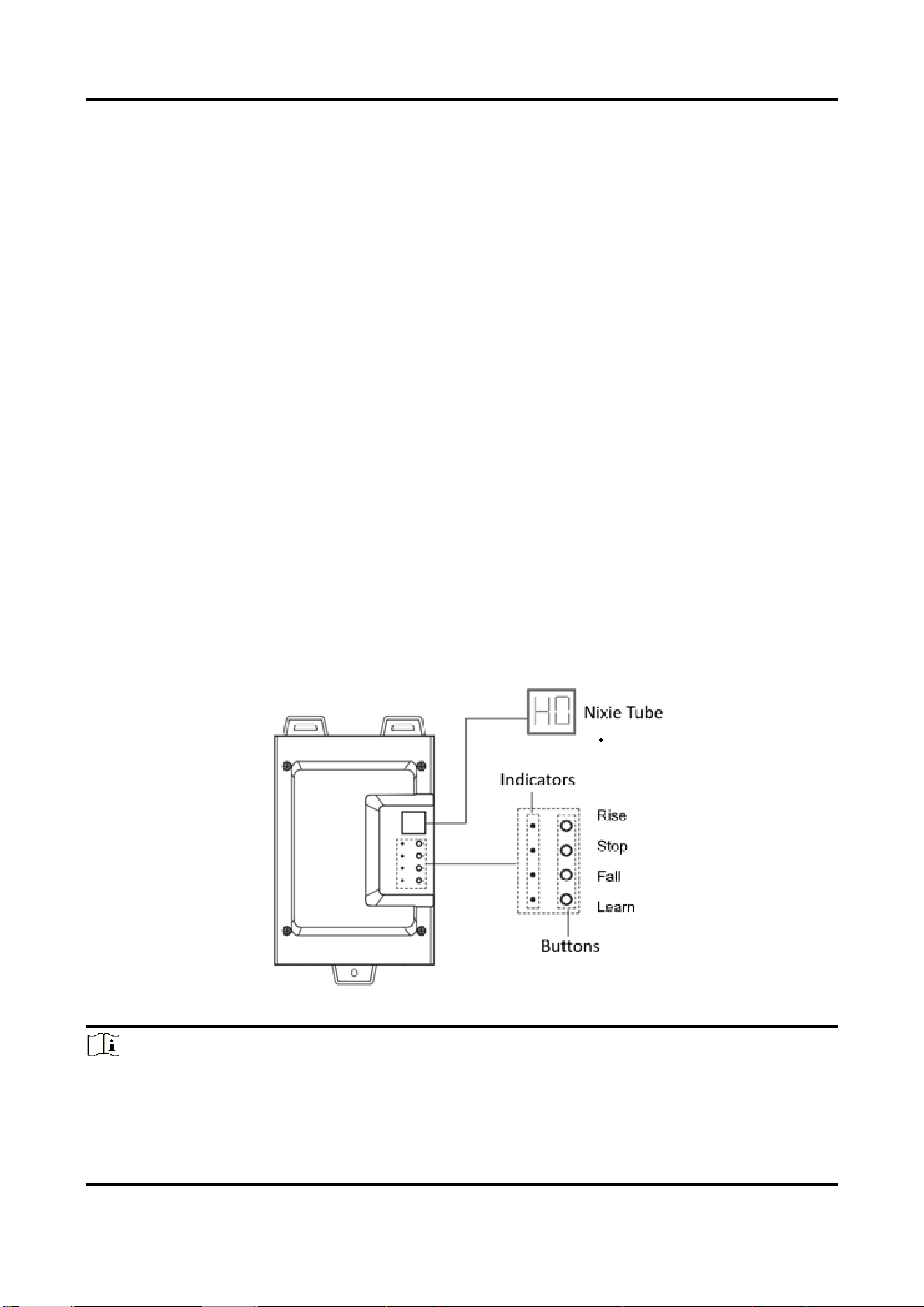
3.2 Set Parameters via Control Board Buttons
3.2.1 Button Description
Open the front cover of the host, and you can see the control board buttons and nixie tube. You
can control the barrier gate via the buttons and judge the status via the nixie tube.
There is respective initial status for the rising limit position, falling limit position, and rising speed
of the barrier gate. You can adjust them via buttons if the initial status cannot meet the
requirements of the installation site.
Figure 3-1 Control Buttons
Note
● If you need to hold the buttons to trigger operations, hold for 3 seconds or above.
● The nixie tube shows the status (e.g., H0) and fault codes (hexadecimal characters, e.g., 1A). If

Barrier Gate User Manual
46
the fault codes appear on the nixie tube, it means there is operation error. Contact the technical
personnel of our company to solve the problems.
3.2.2 Operation Procedure
Refer to the table below for the description of the value on the nixie tube.
Table 3-1 Nixie Tube Value Description
Value
Description
H0
The boom pole is in the rising limit position. Enter into the learning
mode.
H1
To adjust the limit position distance of the boom pole. Refer to Adjust
Limit Position Distance of Boom Pole for details.
H4
To set the remote controller learning. Refer to Set Remote Controller
Learning for details.
H6
To enable the auto falling function of boom pole. Refer to Enable Auto
Falling of Boom Pole for details.
H7
To set the auto falling time of boom pole. Refer to Set Auto Falling
Time of Boom Pole for details.
H8
To enable the function of locking barrier gate via the remote
controller. Refer to Enable Locking Barrier Gate via Remote Controller
for details.
Hb
To set the boom pole type. Refer to Set Boom Pole Type for details.
HC
To set the left/right direction of boom pole. Refer to Set Left/Right
Direction of Boom Pole for details.
Hd
To set the self-learning mode when the device is powered on. Refer to
Set Self-Learning when Powered on for details.
HE
To set the warning light mode. Refer to Set Warning Light Mode for
details.
Note
H2/H3/H5/H9/HA functions are unavailable.
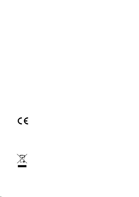
Set Remote Controller Learning
Steps
1. Press the Rise button on the remote controller, press the Rise button on the control board, or
power on the device to adjust the boom pole to the rising limit position.
2. Hold the Learn button on the control board until “H0” appears on the nixie tube.
Barrier Gate User Manual
47
3. Press the Rise/Fall button on the control board to increase/decrease the value on the nixie
tube. Adjust the value to “H4”.
4. Hold the Learn button on the control board until “PA” appears on the nixie tube.
5. Press the Learn button on the control board, or press the Rise, Fall, and Stop buttons on the
remote controller in sequence to save the settings.
6. Press the Rise, Fall, and Stop buttons on the remote controller in sequence until “00” appears
on the nixie tube. Learning completed.
7. (Optional) If you want to unpair the remote controller, hold the Stop button on the control
board until “H4” appears on the nixie tube.
8. Press the Learn button on the control board to save the settings. “H4” will appear on the nixie
tube.
Rising Limit
Position
Press the Rise/Fall button
on the control board to
increase/decrease the value
on the nixie tube.
H4
PA
Hold the Learn button on the control board.
00
Press the Rise, Fall, and Stop buttons
on the remote controller in sequence.
H0
Hold the Learn button on the control board.
Press the Rise button on the remote
controller, press the Rise button on the
control board, or power on the device to
adjust the boom pole to the rising limit
position.
Hold the Stop button on the control board
to unpair the remote controller. H4
Learning completed.
Unparing completed.
Press the Learn button on the control board to save the settings.
H4
Figure 3-2 Set Remote Controller Learning
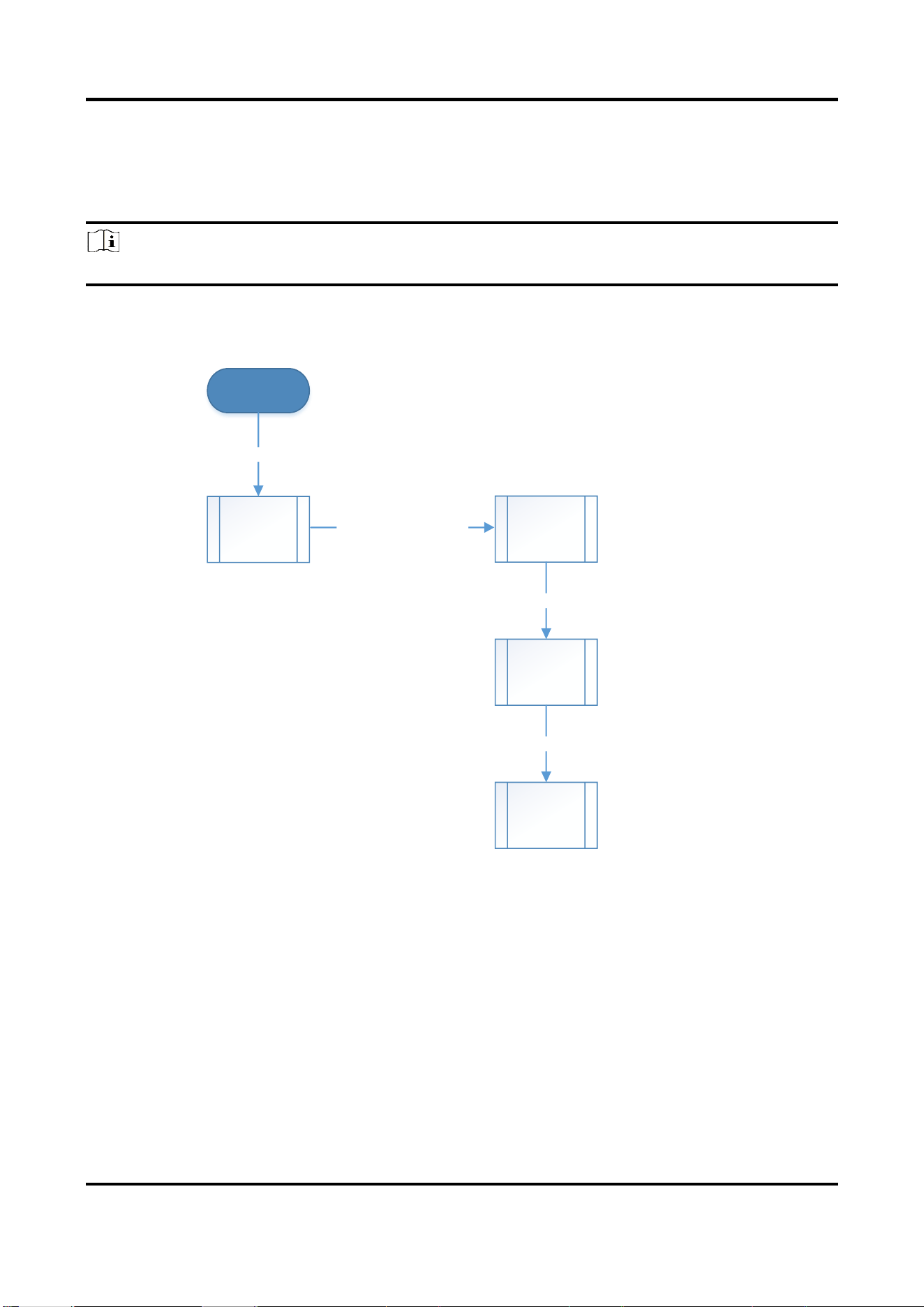
Enable Auto Falling of Boom Pole
Steps
1. Press the Rise button on the remote controller, press the Rise button on the control board, or
power on the device to adjust the boom pole to the rising limit position.
2. Hold the Learn button on the control board until “H0” appears on the nixie tube.
Barrier Gate User Manual
48
3. Press the Rise/Fall button on the control board to increase/decrease the value on the nixie
tube. Adjust the value to “H6”.
4. Hold the Learn button on the control board to enter the menu settings.
5. Press the Rise/Fall button on the control board to adjust the value on the nixie tube.
Note
Adjust the value to 1 to enable the auto falling function, and 0 to disable the function.
6. Press the Learn button on the control board to save the settings. “H6” will appear on the nixie
tube.
Rising Limit
Position
Press the Rise/Fall button
on the control board to
increase/decrease the value
on the nixie tube.
H6
1
Hold the Learn button on the control board to enter the menu settings.
H6
Press the Learn button on the control board to save the settings.
H0
Hold the Learn button on the control board.
Press the Rise/Fall button on
the control board to adjust the
value on the nixie tube.
1: Enable auto falling function.
0: Disable auto falling function.
Press the Rise button on the remote
controller, press the Rise button on the
control board, or power on the device to
adjust the boom pole to the rising limit
position.
Figure 3-3 Enable Auto Falling of Boom Pole
Set Auto Falling Time of Boom Pole
Steps
1. Press the Rise button on the remote controller, press the Rise button on the control board, or
power on the device to adjust the boom pole to the rising limit position.
2. Hold the Learn button on the control board until “H0” appears on the nixie tube.
3. Press the Rise/Fall button on the control board to increase/decrease the value on the nixie
tube. Adjust the value to “H7”.
4. Hold the Learn button on the control board to enter the menu settings.
5. Press the Rise/Fall button on the control board to adjust the value on the nixie tube.

Barrier Gate User Manual
49
Note
The actual auto falling time of the boom pole after the vehicle passes = the value shown on the
nixie tube × 10 s. E.g., the value shown on the nixie tube is 3. Thus the actual auto falling time is 30
s.
6. Press the Learn button on the control board to save the settings. “H7” will appear on the nixie
tube.
Rising Limit
Position
Press the Rise/Fall button
on the control board to
increase/decrease the value
on the nixie tube.
H7
03
Hold the Learn button on the control board to enter the menu settings.
H7
Press the Learn button on the control board to save the settings.
H0
Hold the Learn button on the control board.
Press the Rise/Fall button on the control
board to adjust the value on the nixie
tube.
The actual auto falling time of the boom
pole after the vehicle passes = the value
shown on the nixie tube × 10 s.
Press the Rise button on the remote
controller, press the Rise button on the
control board, or power on the device to
adjust the boom pole to the rising limit
position.
Figure 3-4 Set Auto Falling Time of Boom Pole
Adjust Limit Position Distance of Boom Pole
Steps
1. Press the Fall button on the remote controller or press the Fall button on the control board to
adjust the boom pole to the falling limit position, and “H1” will appear on the nixie tube.
2. Hold the Learn button on the control board. Then press the Rise/Fall button on the control
board to increase/decrease the value on the nixie tube.
Note
● The function is only valid for the boom pole of 5 m or above.
● If you press the Rise button, it means the motor rotation turns increase one. If you press the
Fall button, it means the motor rotation turns reduce one.
● The value on the nixie tube means the number of motor rotation turns. E.g., if you press the
Rise button on the control board to adjust the value to 5, it means the motor rotates 5 turns

Barrier Gate User Manual
50
away from the initial falling limit position.
3. Press the Learn button on the control board to save the settings. “00” will appear on the nixie
tube.
Falling Limit
Position
H1
5
Hold the Learn button on the control board.
00
Press the Learn button on the control board to save the settings.
Press the Fall button on the remote
controller or press the Fall button on the
control board to adjust the boom pole to
the falling limit position.
Press the Rise/Fall button on the control
board to increase/decrease the value on the
nixie tube.
Rise: The motor rotation turns increase one.
Fall: The motor rotation turns reduce one.
Figure 3-5 Adjust Limit Position Distance of Boom Pole
Enable Locking Barrier Gate via Remote Controller
Steps
1. Press the Rise button on the remote controller, press the Rise button on the control board, or
power on the device to adjust the boom pole to the rising limit position.
2. Hold the Learn button on the control board until “H0” appears on the nixie tube.
3. Press the Rise/Fall button on the control board to increase/decrease the value on the nixie
tube. Adjust the value to “H8”.
4. Hold the Learn button on the control board to enter the menu settings.
5. Press the Rise/Fall button on the control board to adjust the value on the nixie tube.
Note
Adjust the value to 1 to enable locking barrier gate via the remote controller, and 0 to disable the
function.
6. Press the Learn button on the control board to save the settings. “H8” will appear on the nixie
tube.
Barrier Gate User Manual
51
Rising Limit
Position
Press the Rise/Fall button
on the control board to
increase/decrease the value
on the nixie tube.
H8
1
Hold the Learn button on the control board to enter the menu settings.
H8
Press the Learn button on the control board to save the settings.
H0
Hold the Learn button on the control board.
Press the Rise/Fall button on the control
board to adjust the value on the nixie
tube.
1: Enable locking barrier gate via the
remote controller.
0: Disable locking barrier gate via the
remote controller.
Press the Rise button on the remote
controller, press the Rise button on the
control board, or power on the device to
adjust the boom pole to the rising limit
position.
Figure 3-6 Enable Locking Barrier Gate via Remote Controller
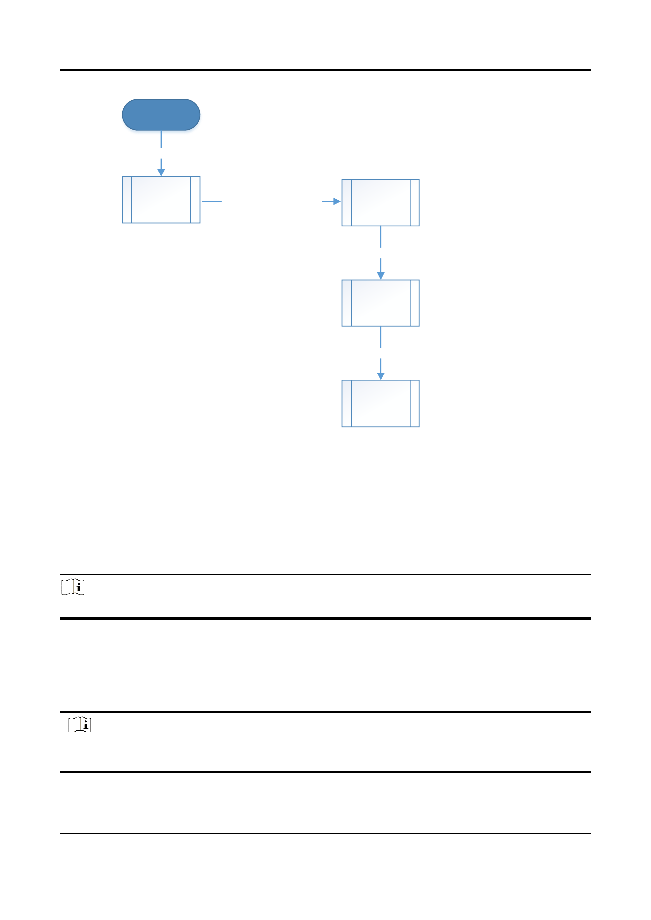
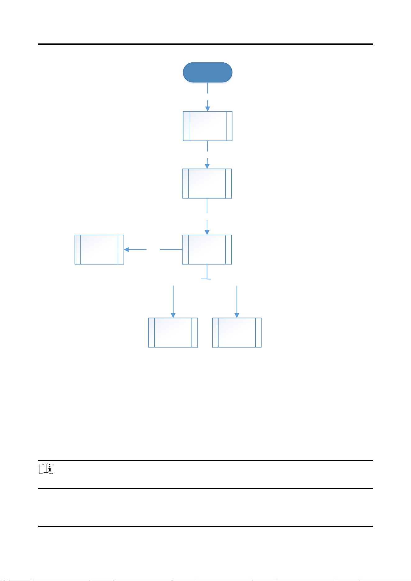
Lock Barrier Gate
Steps
1. Press the Rise button on the remote controller, press the Rise button on the control board, or
power on the device to adjust the boom pole to the rising limit position.
2. Hold the Learn button on the control board until “H0” appears on the nixie tube.
3. Hold the Learn button again on the control board until “Lr” appears on the nixie tube.
4. After the learning process completes, “00” will appear on the nixie tube.
Note
If there is any fault, “06” will appear on the nixie tube. Refer to FAQ for the troubleshooting.
5. Lock the barrier gate via two modes.
● Lock the barrier gate via the camera until “Lc” appears on the nixie tube. The operation
can take effect after 3 s or above.
● Lock the barrier gate via the remote controller. Press the Rise, Stop, and Rise buttons on
the remote controller in sequence until “rL” appears on the nixie tube.
Note
If you want to unlock the barrier gate, you can only unlock via the remote controller. Press the
Rise, Stop, and Rise buttons on the remote controller in sequence to unlock the barrier gate.
Barrier Gate User Manual
52
Lr
00
Learning completed.
Lc
Lock Barrier Gate via
Camera
06
Faults
Effective for 3 s
or above
rL
Lock Barrier Gate via
Remote Controller
Press the Rise, Stop, and Rise
buttons on the remote
controller in sequence.
Rising Limit
Position
H0
Hold the Learn button on the control board.
Press the Rise button on the remote
controller, press the Rise button on the
control board, or power on the device to
adjust the boom pole to the rising limit
position.
Hold the Learn button on the control board.
Figure 3-7 Lock Barrier Gate
Set Boom Pole Type
Steps
1. Press the Rise button on the remote controller, press the Rise button on the control board, or
power on the device to adjust the boom pole to the rising limit position.
2. Hold the Learn button on the control board until “H0” appears on the nixie tube.
3. Press the Rise/Fall button on the control board to increase/decrease the value on the nixie
tube. Adjust the value to “Hb”.
4. Hold the Learn button on the control board to enter the menu settings.
5. Press the Rise/Fall button on the control board to adjust the value on the nixie tube.
Note
Refer to Table 3-1 for the value description.

Barrier Gate User Manual
53
6. Press the Learn button on the control board to save the settings. “Hb” will appear on the nixie
tube.
Table 3-2 Boom Pole Type Value Description
Value
Boom Pole Type
2
2 m straight boom pole
3
3 m straight boom pole
4
4 m straight boom pole
5
5 m straight boom pole
6
6 m straight boom pole
3F
3 m fence boom pole
4F
4 m fence boom pole
5F
5 m fence boom pole
3L
3 m boom pole with strip light
4L
4 m boom pole with strip light
4r
4 m round boom pole
3c
3 m folding boom pole
4c
4 m folding boom pole
5c
5 m folding boom pole

Barrier Gate User Manual
54
Rising Limit
Position
Press the Rise/Fall button
on the control board to
increase/decrease the value
on the nixie tube.
Hb
5F
Hold the Learn button on the control board to enter the menu settings.
Hb
Press the Learn button on the control board to save the settings.
H0
Hold the Learn button on the control board.
Press the Rise/Fall button on the control
board to adjust the value on the nixie
tube.
Press the Rise button on the remote
controller, press the Rise button on the
control board, or power on the device to
adjust the boom pole to the rising limit
position.
Figure 3-8 Set Boom Pole Type
Set Left/Right Direction of Boom Pole
Steps
1. Press the Rise button on the remote controller, press the Rise button on the control board, or
power on the device to adjust the boom pole to the rising limit position.
2. Hold the Learn button on the control board until “H0” appears on the nixie tube.
3. Press the Rise/Fall button on the control board to increase/decrease the value on the nixie
tube. Adjust the value to “HC”.
4. Hold the Learn button on the control board to enter the menu settings.
5. Press the Rise/Fall button on the control board to adjust the value on the nixie tube.
Note
Adjust the value to “L” to switch the boom pole to the left direction, and “r” to the right direction.
6. Press the Learn button on the control board to save the settings. “HC” will appear on the nixie
tube.

Barrier Gate User Manual
55
Rising Limit
Position
Press the Rise/Fall button
on the control board to
increase/decrease the value
on the nixie tube.
HC
r/L
Hold the Learn button on the control board to enter the menu settings.
HC
Press the Learn button on the control board to save the settings.
H0
Hold the Learn button on the control board.
Press the Rise/Fall button on the control
board to adjust the value on the nixie
tube.
L: Left direction machine core.
r: Right direction machine core.
Press the Rise button on the remote
controller, press the Rise button on the
control board, or power on the device to
adjust the boom pole to the rising limit
position.
Figure 3-9 Set Left/Right Direction of Boom Pole
Set Self-Learning when Powered on
Steps
1. Press the Rise button on the remote controller, press the Rise button on the control board, or
power on the device to adjust the boom pole to the rising limit position.
2. Hold the Learn button on the control board until “H0” appears on the nixie tube.
3. Press the Rise/Fall button on the control board to increase/decrease the value on the nixie
tube. Adjust the value to “Hd”.
4. Hold the Learn button on the control board to enter the menu settings.
5. Press the Rise/Fall button on the control board to adjust the value on the nixie tube.
Note
“1” means to keep the boom pole status as fallen when the barrier gate is powered on. “0” means
to learn the rising limit position when the barrier gate is powered on.
6. Press the Learn button on the control board to save the settings. “Hd” will appear on the nixie
tube.
Barrier Gate User Manual
56
Rising Limit
Position
Press the Rise/Fall button
on the control board to
increase/decrease the value
on the nixie tube.
Hd
0
Hold the Learn button on the control board to enter the menu settings.
Hd
Press the Learn button on the control board to save the settings.
H0
Hold the Learn button on the control board.
Press the Rise/Fall button on the control
board to adjust the value on the nixie
tube.
1: Keep the boom pole status as fallen
when the barrier gate is powered on.
0: To learn the rising limit position when
the barrier gate is powered on.
Press the Rise button on the remote
controller, press the Rise button on the
control board, or power on the device to
adjust the boom pole to the rising limit
position.
Figure 3-10 Set Self-Learning when Powered on
Set Warning Light Mode
Steps
1. Press the Rise button on the remote controller, press the Rise button on the control board, or
power on the device to adjust the boom pole to the rising limit position.
2. Hold the Learn button on the control board until “H0” appears on the nixie tube.
3. Press the Rise/Fall button on the control board to increase/decrease the value on the nixie
tube. Adjust the value to “HE”.
4. Hold the Learn button on the control board to enter the menu settings.
5. Press the Rise/Fall button on the control board to adjust the value on the nixie tube.
Note
“1” is the warning light mode. “0” is the falling limit output mode.
6. Press the Learn button on the control board to save the settings. “HE” will appear on the nixie
tube.
Barrier Gate User Manual
57
Rising Limit
Position
Press the Rise/Fall button
on the control board to
increase/decrease the value
on the nixie tube.
HE
0
Hold the Learn button on the control board to enter the menu settings.
HE
Press the Learn button on the control board to save the settings.
H0
Hold the Learn button on the control board.
Press the Rise/Fall button on the control
board to adjust the value on the nixie
tube.
1: Warning light mode.
0: Falling limit output mode.
Press the Rise button on the remote
controller, press the Rise button on the
control board, or power on the device to
adjust the boom pole to the rising limit
position.
Figure 3-11 Set Warning Light Mode
Barrier Gate User Manual
58
Chapter 4 Maintenance
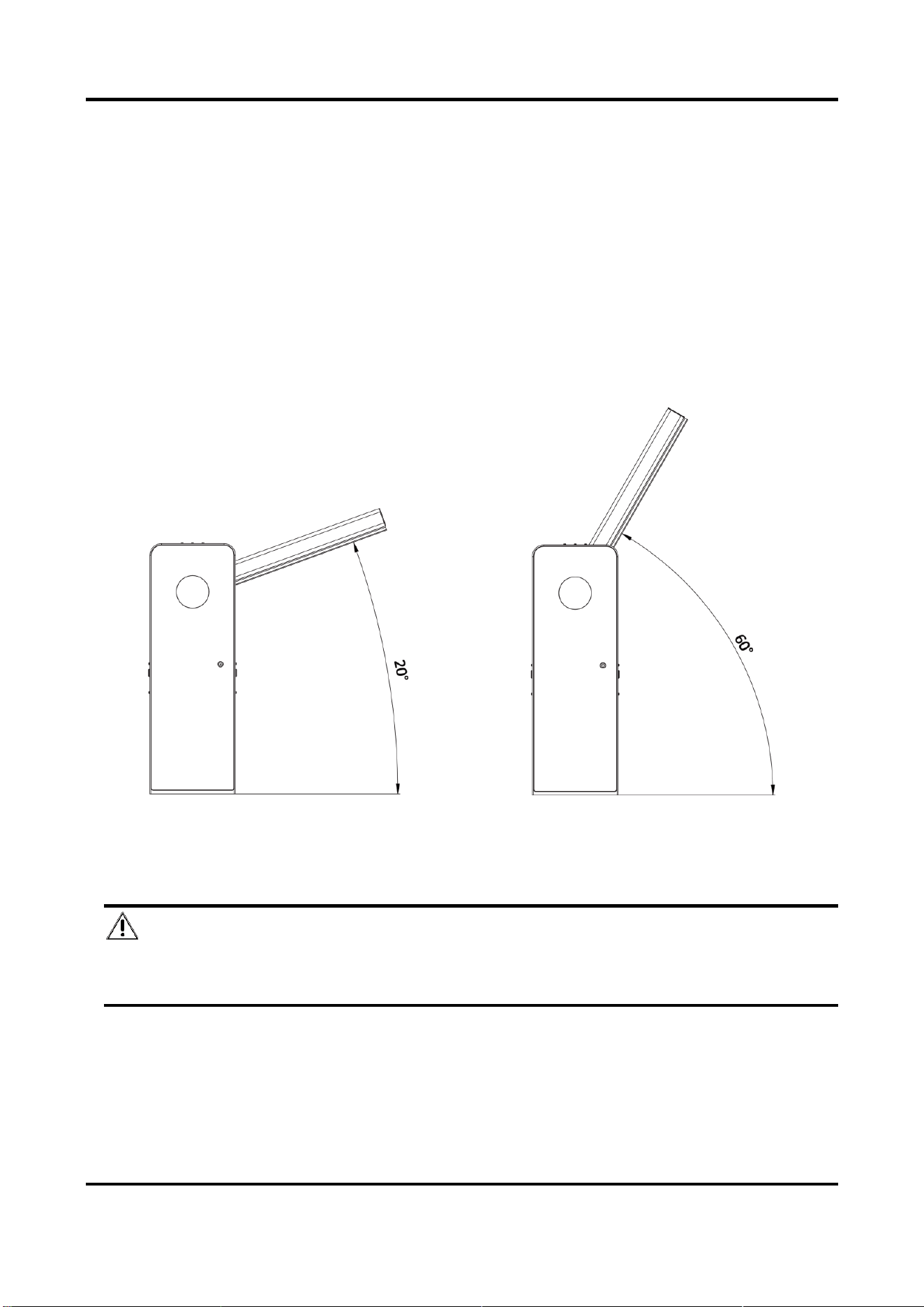
4.1 Adjust Boom Pole Balance
Adjust the balance of the boom pole.
Steps
1. Cut off the power supply. Rotate the hand wheel of the machine core to raise the boom pole to
the position where the angle between the boom pole and the ground surface is 20° ± 5°.
2. Release the hand wheel to check if the boom pole can return to the position where the angle
between the boom pole and the ground surface is 60° ± 15° naturally.
Figure 4-1 Adjust Boom Pole Balance
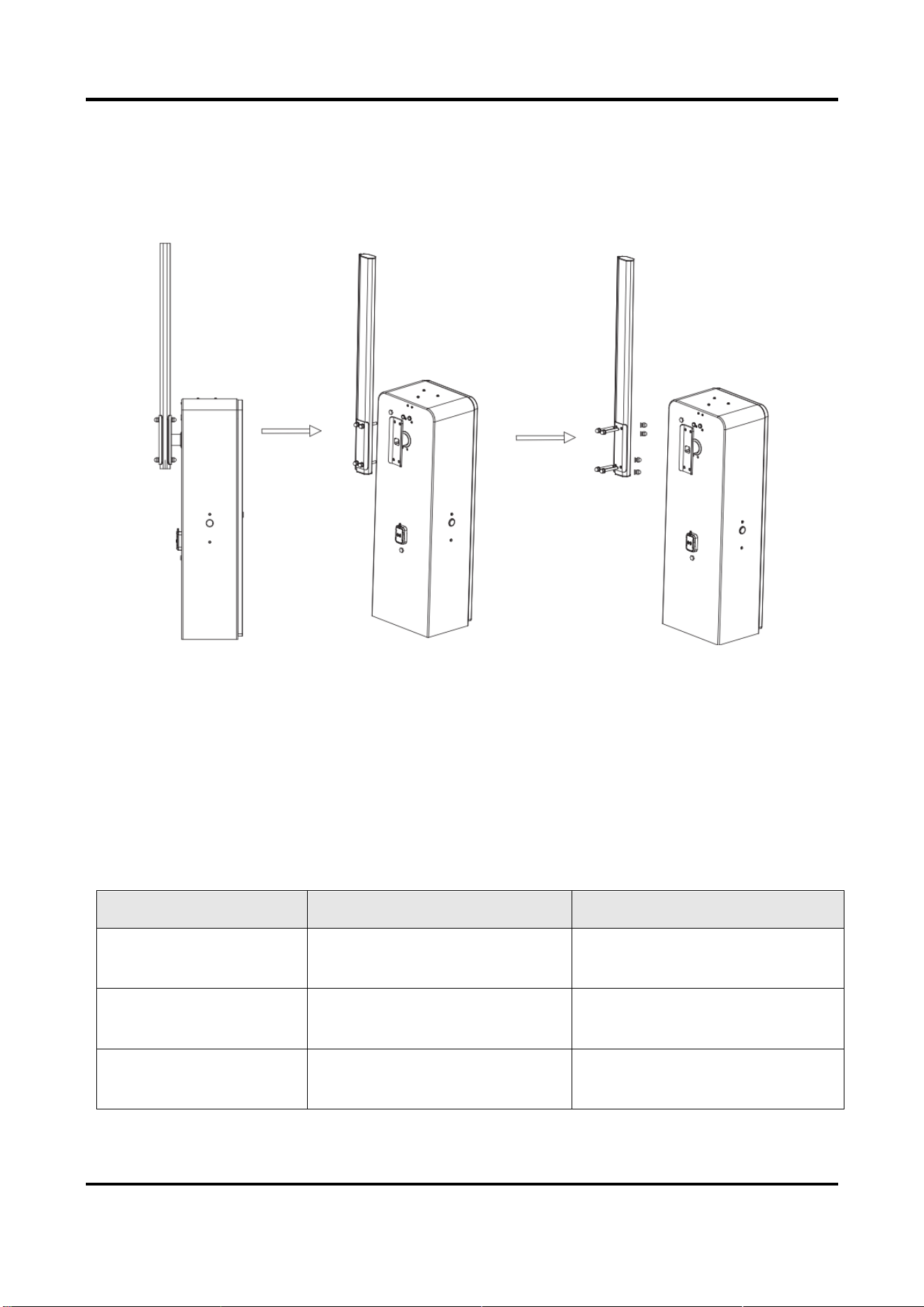
4.2 Change Boom Pole
Caution
Contact the professional technical personnel to change the boom pole. You may damage the
barrier gate if you change it by yourself.
Before you start
Cut off the power supply, and adjust the boom pole to the falling limit position.
Barrier Gate User Manual
59
Steps
1. Unscrew the cap nuts, spring washers, and flat washers on the other sides of the four
assembling bolts. Save the components and parts for the following installations.
2. Disassemble the boom pole and chuck.
3. Repeat the boom pole installation procedure to install a new boom pole.
Figure 4-2 Change Boom Pole
4.3 Change Spindle Rod and Spring
4.3.1 Spring and Spindle Rod Specifications
If you need to change the boom pole, prepare the corresponding springs and spindle rods
according to the boom pole types. Refer to the table below for details.
Table 4-1 Spring and Spindle Rod Specifications
Boom Pole Type
Spring
Spindle Rod
2 m octagonal straight
boom pole
Small spring with green hook × 1
Small octagonal boom pole
spindle rod
3 m octagonal straight
boom pole
Medium spring with white hook
× 1
Small octagonal boom pole
spindle rod
4 m octagonal straight
boom pole
Small spring with green hook × 2
Small octagonal boom pole
spindle rod

Barrier Gate User Manual
60
4.3.2 Change Spindle Rod
Before you start
Cut off the power supply, and adjust the boom pole to the falling limit position.
Steps
1. Unscrew the cap nuts, spring washers, and flat washers on the other sides of the four
assembling bolts. Save the components and parts for the following installations.
5 m octagonal straight
boom pole
Large spring with red hook × 1
Large octagonal boom pole
spindle rod
6 m octagonal straight
boom pole
Small spring with green hook × 1
Large spring with red hook × 1
Large octagonal boom pole
spindle rod
3 m fence boom pole
Medium spring with white hook
× 2
Large octagonal boom pole
spindle rod
4 m fence boom pole
Small spring with green hook × 1
Large spring with red hook × 1
Large octagonal boom pole
spindle rod
5 m fence boom pole
Large spring with red hook × 2
Large octagonal boom pole
spindle rod
1.5 m + 1.5 m folding
boom pole
Medium spring with white hook
× 1
Small octagonal boom pole
spindle rod
2.5 m + 2.5 m folding
boom pole
Large spring with red hook × 1
Small octagonal boom pole
spindle rod
2 m anti-collision cylinder
boom pole
Small spring with green hook × 1
Anti-collision round boom pole
spindle rod
3 m anti-collision
cylinder boom pole
Medium spring with white hook
× 1
Anti-collision round boom pole
spindle rod
4 m anti-collision
cylinder boom pole
Small spring with green hook × 1
Medium spring with white hook
× 1
Anti-collision round boom pole
spindle rod
4 m boom pole with
strip light
Small spring with green hook × 1
Medium spring with white hook
× 1
Spindle rod for boom pole with
strip light
3 m boom pole with
strip light
Medium spring with white hook
× 1
Spindle rod for boom pole with
strip light
Barrier Gate User Manual
61
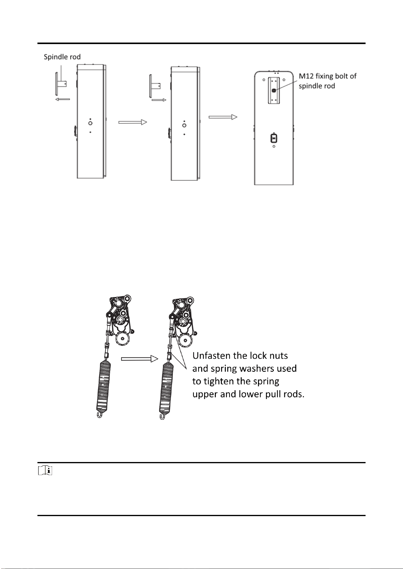
2. Disassemble the boom pole and chuck.
Figure 4-3 Disassemble Boom Pole and Chuck
3. Unscrew the M12 fixing bolt of the spindle rod anticlockwise with a 10 mm hex wrench, and
disassemble the bolt.
Figure 4-4 Disassemble Bolt
4. Disassemble the spindle rod and change a new one. Install the M12 fixing bolt of the spindle
rod, and fasten it with a torque no smaller than 60 NM.
Barrier Gate User Manual
62
Figure 4-5 Change Spindle Rod
5. Repeat the boom pole installation procedure to install a new boom pole.
4.3.3 Change Spring
Before you start
Cut off the power supply, and adjust the boom pole to the rising limit position.
Steps
1. Unfasten the lock nuts and spring washers used to tighten the spring upper and lower pull
rods.
Figure 4-6 Unfasten Lock Nuts and Spring Washers
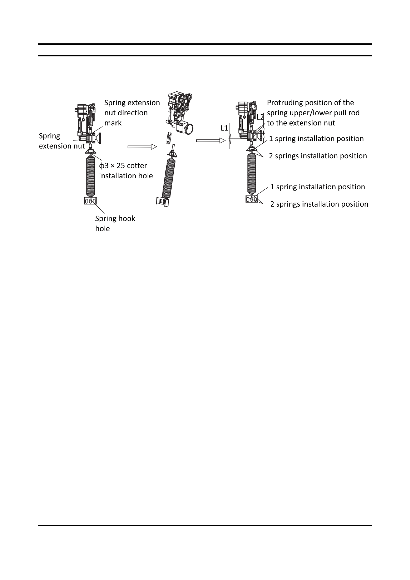
2. Unfasten the spring extension nut, and disassemble the spring lower pull rod.
3. Disassemble the limit position cotter pin of the spring pull rod, change the spring, and install
the limit position cotter pin.
Note
For different number of springs, operate according to the figure shown below.
Barrier Gate User Manual
63
4. Screw the spring extension nut into the spring upper and lower pull rods. Make sure that the
protruding length of the spring upper pull rod to the extension nut (L1) and that of the spring
lower pull rod to the extension nut (L2) is nearly the same.
Figure 4-7 Change Spring
5. Fasten the spring extension nut until the boom pole meets the balance standard.
4.4 Change Machine Core
Before you start
Cut off the power supply. Disassemble the boom pole, spindle rod, and spring according to the
procedure above.
Steps
1. Unplug the machine core power cord and signal line plugs on the barrier gate control board.
2. Operate the hand wheel to expose the machine core fixing bolts. Disassemble the fixing bolts
with an 8 mm hex wrench.
3. Install a new machine core, and fasten the fixing bolts to the corresponding installation holes.
4. Install the spring. Refer to 4.3.3 Change Spring for details.
5. Install the boom pole. Refer to 4.2 Change Boom Pole for details.
6. Adjust the boom pole and spring according to the balance standard.

Barrier Gate User Manual
64
Figure 4-8 Change Machine Core
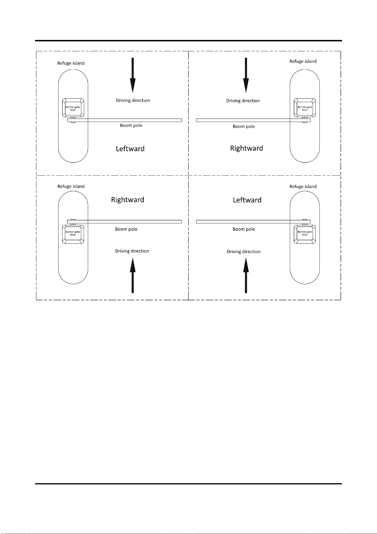
4.5 Left/Right Direction of Boom Pole
The boom pole direction depends on the driving direction of the vehicle. When you look from the
driving direction as shown below, the left boom pole is the one that the boom pole is on the left of
the barrier gate host, and the right boom pole is the one that the boom pole is on the right of the
barrier gate host.
Barrier Gate User Manual
65
Figure 4-9 Boom Pole Direction Instruction
For some models of the barrier gate, the boom pole direction can be changed. For some models of
the barrier gate, the boom pole direction cannot be changed. Refer to the figure below for the
relationship between barrier gate models and boom pole directions.

Barrier Gate User Manual
66
Figure 4-10 Relationship Between Barrier Gate Models and Boom Pole Directions

Barrier Gate User Manual
67
4.6 Change Left/Right Direction of Machine Core
Before you start
Cut off the power supply. Disassemble the machine core according to the procedure above.
Steps
1. Disassemble the 2 cap screws to tighten the output shaft, the 2 cap screws to fix the limit
positions, and the 1 cap screw to tighten the crank arm in sequence.
Figure 4-11 Disassemble Cheese Head Bolts
2. Distract the rocker with a 7 mm bevel tool, and remove the whole linkage arm component
with a rubber hammer.
Figure 4-12 Disassemble Linkage Arm Component
3. Remove the 2 circlips used to fix the linkage arm with a circlip plier, and remove the linkage
arm with a hammer or other tools. Rotate the crank arm 180°. Install the linkage arm and fix
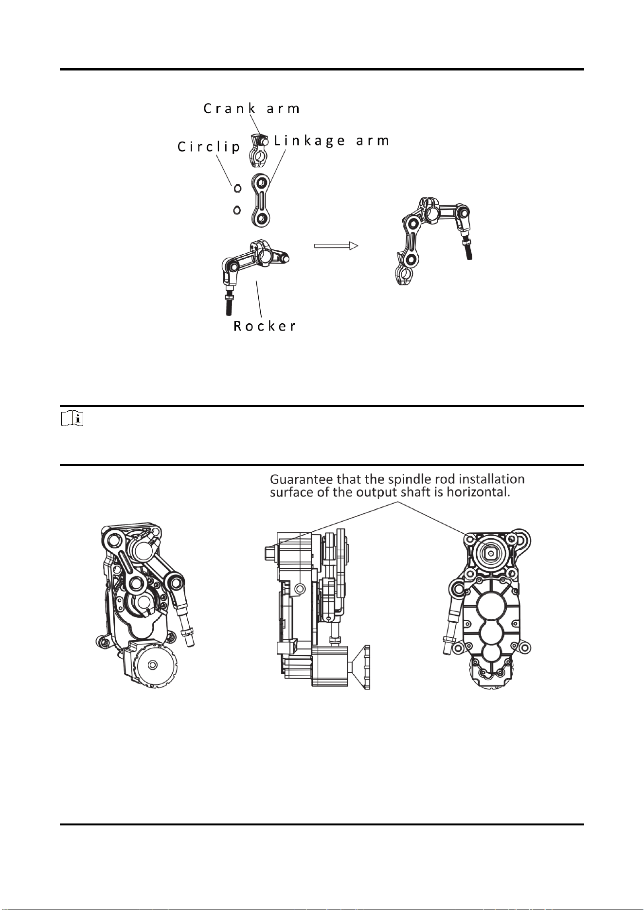
Barrier Gate User Manual
68
the circlips.
Figure 4-13 Disassemble and Reinstall Crank Arm, Linkage Arm, and Rocker
4. Install the left-direction linkage arm component to the machine core with the rubber hammer.
Fix the cap screws to fix the limit positions, the cap screw to tighten the crank arm, and the cap
screws to tighten the output shaft in sequence.
Note
During the linkage arm component installation process, operate the hand wheel to adjust the
position to guarantee that the spindle rod installation surface of the output shaft is horizontal.
Figure 4-14 Install Linkage Arm Component
Barrier Gate User Manual
69
Figure 4-15 Machine Core Installation Position
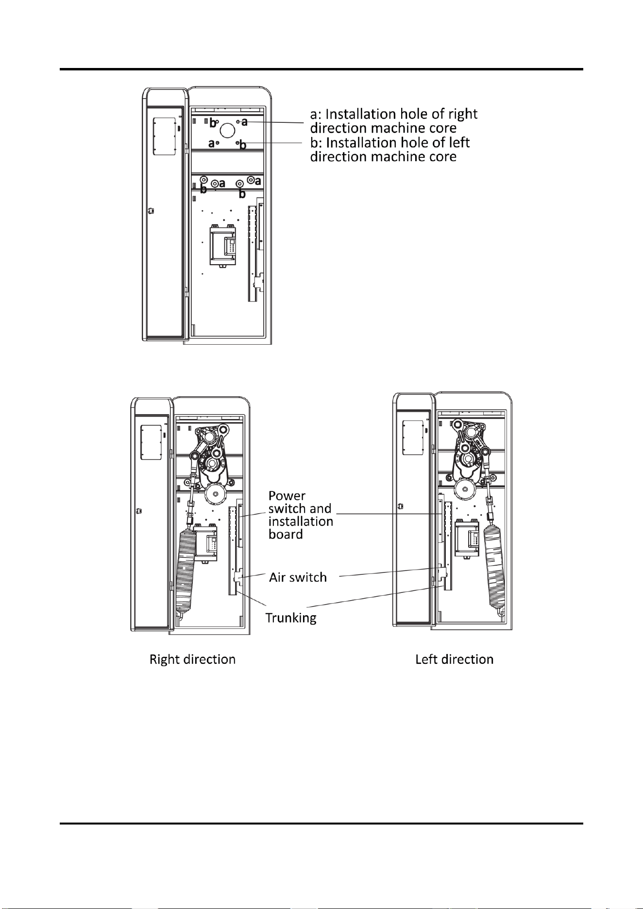
5. Change the trunking, power switch and installation board, and the positions of the air switch
and spring to switch the left and right directions.
Figure 4-16 Change Other Components
6. Install the spring. Refer to 4.3.3 Change Spring for details.
7. Install the boom pole. Refer to 4.2 Change Boom Pole for details.
8. Adjust the boom pole and spring according to the balance standard.

Barrier Gate User Manual
70
A. FAQ
Fault Code on
Nixie Tube
Fault Name
Troubleshooting
Remarks
“00”
No error.
No error.
“01”
Hardware
overcurrent
1. Check if there is short circuit
of the motor or the control
board.
2. Check if there is extreme load
in operation.
1. The barrier gate can
operate normally only
after the boom pole is
installed properly.
2. Check if the barrier gate
spring balance meets
requirements that the
boom pole can rebound to
60° if you push the boom
pole down to 20°.
3. Check if the mechanical
structures are smooth.
4. Change other well-
functioning control boards
to test (Pay attention to
the control board
program).
“02”
Software overflow
1. Check if there is overload in
operation.
2. Check if the machine core
spring is installed correctly.
“03”
Resistance
This error will be cleared
automatically and will not be
displayed.
“04”
Overload
1. Check the possibility of
overload.
2. Check if the machine core
spring is installed correctly.
“06”
Bus bar
overvoltage
1. Check if the bus bar is in
prolonged overvoltage status.
2. Check if the power supply is
mismatched. Check if the motor
is reversed manually. Check the
possibility of braking resistor
failure.
“07”
Bus bar
undervoltage
1.Check if the bus bar is in
prolonged undervoltage status.
2. Check if the power supply is
mismatched. Check if there is
short circuit of the motor,
power supply, or braking
resistor.

Barrier Gate User Manual
71
“0d”
Rising/Falling limit
fault
1. Check if the gear has lost
teeth.
2. Check if the rising/falling limit
is damaged.
“0E”
Anti-fall learning
fault
Learn the anti-fall or protection
signal act. Eliminate
interference and press rise
button to clear the error and
learn again.
“10”
Short circuit of
the stopping
control/stopping
via handle port
Check if there is short circuit of
the stopping control/stopping
via handle port.
“11”
Short circuit of
the falling
control/falling via
handle port
Check if there is short circuit of
the falling control/falling via
handle port.
“17”
Braking resistor
exception
Check the installation status of
the current braking resistor.
42 resistor is integrated in
the main board. If error
occurs, change other well-
functioning main board to
test.
“18”
Hall loss
Check if the hall signal line is
broken or not connected.
“64”
Rising boom pole
for 60 s timed
out.
1. Check if the boom pole is
balanced.
2. Check if the structure is stuck.
“66”
Learning in 60 s
timed out.
1. Check if the gear has lost
teeth.
2. Check if the rising or falling
limit is damaged.
“69”
FLASH exception
Check the connection status of
the external FLASH chip and
change a control board.

UD30852B-A