Loading ...
Loading ...
- www.jyetech.com -
JYE Tech Ltd.
Page 3
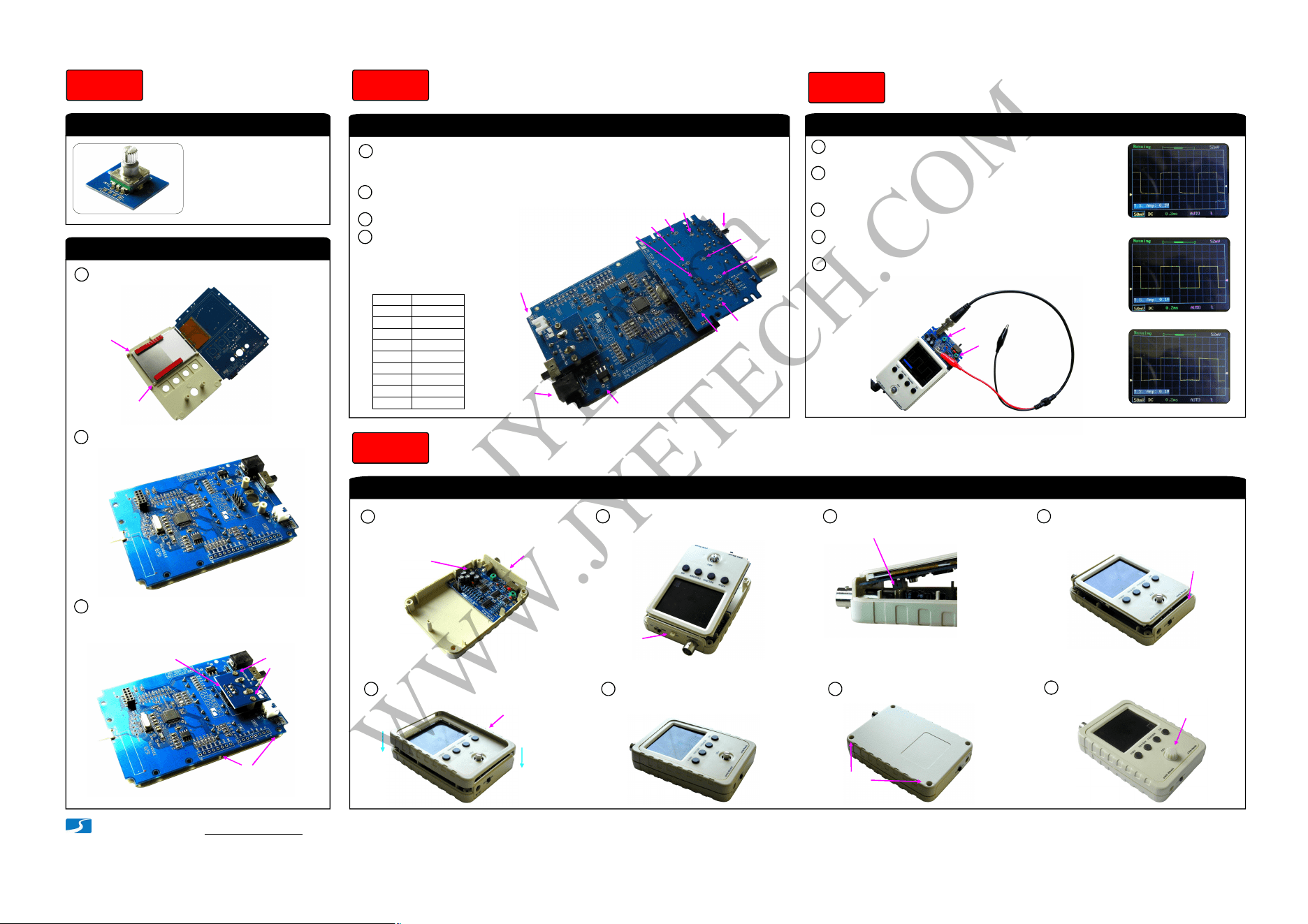
2. Assemble Front Module
1. Solder Rotary Encoder
Note:
Please pay attention to the
orientation of PCB. Use the
side with outline marking.
Assembly Front Module
Step 3
Verify voltages on the analog board
Check Voltages
Step 4
Fit LCD to front panel as shown below.1
2
Fold the main board over while keeping
LCD in place.
Final assembly
Put all parts together
Step 6
3
Mount rotary encoder board to the
front plate with screws and solder the
board to J2 of the main board.
Mount with
screws
(KA2x4)
Make sure PCB evenly
touch the front plate
while doing C.
A.
B.
C. Solder here
Calibration
Step 5
Screw the analog board to
back cover with the top
bracket attached
1
Combine the front module and
the back cover
2
Screws
KA2x4
Top bracket
Put test signal
terminal through
the small slot
Make sure receptacle (J4)
mate with pin-header (J2)
3
Attach bottom bracket before
holding the two modules
together
4
Bottom bracket
Attach the front frame
5
Firmly press the frame in
6
Front frame
Screw up at the back
7
Screws
(4 positions)
PA2.3x8
Attach knob cap and done!
8
Knob cap
Attach the analog board to the main board
by mating J3 on the analog board to J4 on
the main board (see photo).
1
2
Apply 9V DC power supply to J7 (or J6) on
the main board.
3
Set couple switch to GND position.
Check voltages at the points
as shown in the photo.
4
V1
V2
V3
V4
V5
AV+
V-
AV-
V+
Input
V+
AV+
V-
AV-
V1
V2
V3
V4
V5
+9.20V
+8.25V
+6.87V
-7.14V
-5.55V
0V
0V
0V
+1.44V
-0.98V
References
(*)
(*)
(*)
(*)
(*) Input dependent
Place negative
pen at DGND
Couple
switch
Apply power
here
C3
C5
Connect the red clip to the test signal terminal and leave the
black clip un-connected (see photo at bottom).
1
2
Apply power and boot. Hold down ADJ dial for 3 seconds to
bring up Test Signal amplitude display at lower-left corner.
Push ADJ to set the amplitude to 0.1V.
3
Set sensitivity to 50mV and adjust trigger level so that
waveform stable (see “How to Use” at page 4).
Not enoughA.
GoodB.
Too muchC.
4
Tuning C3 so that sharp rectangle (photo B at left) is obtained.
The adjustment for C3 is done.
5
Push ADJ to set the amplitude to 3.3V. Change sensitivity to
1V. Tuning C5 so that sharp rectangle waveform is obtained.
The adjustment is done.
Adjust trimmers C3 and C5
Mount to the small PCB
(PN: 109-15002-00A)
AV- = -4.5V ~ -8V and
AV+ = +5V ~ +8V
are acceptable
Note:
(4 positions)
Important !
Always remove power before
connecting or disconnecting
the analog board.
Important !
Tips:
Perform VPos alignment
before calibrating C3 and C5.
JYE Tech
WWW.JYETECH.COM
Loading ...