Loading ...
Loading ...
Loading ...
En-4
2-2. CONNECTING WIRES FOR OUTDOOR UNIT
• Besuretousespecialcircuitsforroomairconditioner.
• Wiringworkshouldbebasedonapplicabletechnicalstandards.
• Wiringconnectionsshouldbemadefollowingthediagram.
• Screwsshouldbetightenedsotheywon’tloosen.
ELECTRICAL SPECIFICATIONS
OUTDOOR UNIT
MXZ-2C20NA2
Power supply
(V,PHASE,Hz)
208/230, 1, 60
Max. Fuse size
(time delay) (A)
20
Min. Circuit
Ampacity (A)
17.2
Fan motor
(F.L.A)
1.77
Com-
pressor
(R.L.A) 10.7
(L.R.A) 15.5
Controlvoltage
Indoor unit-Remote controller : (Wireless)
Indoorunit-Outdoorunit:DC12-24V
1-3/8 in.
(35 mm)
5/8 in.
(15 mm)
Lead wire
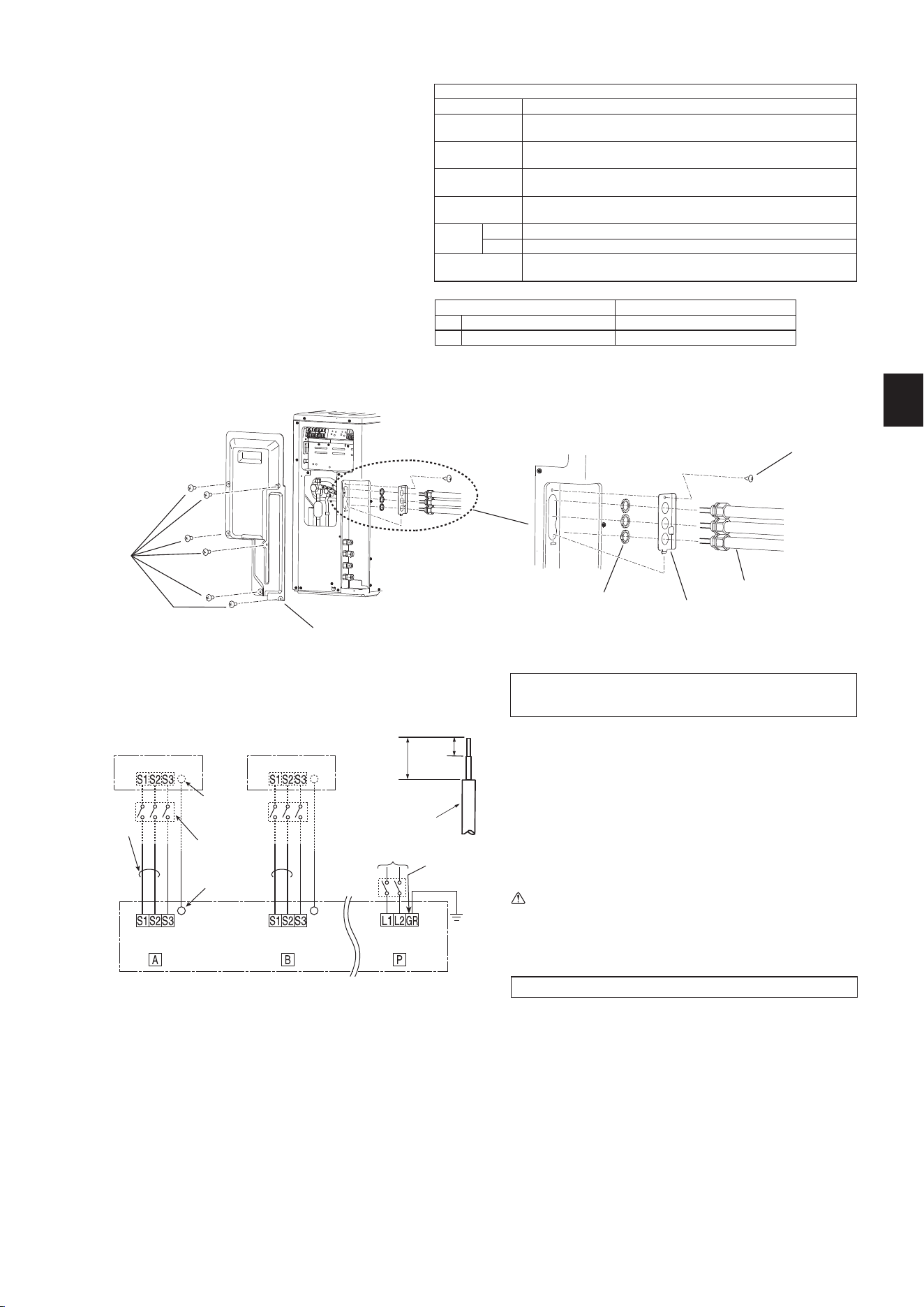
1)Removetheservicepanel.
2)Removetheconduitplate.
3)Attachtheconduitconnectortoconduitplatewithlocknutthensecure
ittotheunitwithscrews.Besuretoattachtheconduitconnectorsin
the correct locations according to their sizes.
4)ConnectgroundwirestotheTBbed.
5) Loosen terminal screw, and connect indoor/outdoor unit connecting
wire(B)fromtheindoorunitcorrectlyontheterminalblock.Becareful
nottomakemis-wiring.Fixthewiretotheterminalblocksecurelyso
thatnopartofitscoreisappeared,andnoexternalforceisconveyed
totheconnectingsectionoftheterminalblock.
6)Firmlytightentheterminalscrewstopreventthemfromloosening.After
tightening,pullthewireslightlytoconrmthattheydonotmove.
7) Perform 5) and 6) for each indoor unit.
8) Connect power supply cord (A).
9)Closetheservicepanelsecurely.Makesurethat3-2.PIPECONNEC-
TION is completed.
CONNECTING WIRES AND CONNECTING GROUND WIRE
• UsesolidconductorMin.AWG14orstrandedconductorMin.AWG14.
• Usedoubleinsulatedcopperwirewith600Vinsulation.
• Usecopperconductorsonly.
* Follow local electrical code.
POWER SUPPLY CABLE
• UsesolidorstrandedconductorMin.AWG8.
• Usecopperconductorsonly.
* Follow local electrical code.
GROUND WIRE
• UsesolidorstrandedconductorMin.AWG8.
• Usecopperconductorsonly.
* Follow local electrical code.
WARNING:
• Usetheindoor/outdoorunitconnectingwirethatmeetstheStand-
ardstoconnecttheindoorandoutdoorunitsandxthewireto
the terminal block securely so that no external force is conveyed
to the connecting section of the terminal block. An incomplete
connectionorxingofthewirecouldresultinare.
Remark:
* Use a ring tongue terminal in order to connect a ground wire to terminal.
• Connectwirestothematchingnumbersofterminals.
• Besuretoattacheachscrewtoitscorrespondentterminalwhen
securing the cord and/or the wire to the terminal block.
Terminalblock
Grounding
terminal *
208/230 V AC
1 phase 60 Hz
Grounding
terminal *
Terminalblock
Ground
OUTDOOR UNIT
Power supply
208/230VAC
1phase2wires60Hz
Disconnect
switch
Grounding
terminal *
Terminalblock Terminalblock
Terminalblock
Forfutureservicing,giveextralengthtotheconnectingwires.
Conduit connector Trade size of conduit
(a) Power supply 3/4 in.
(b) Indoor/outdoor 1/2 in.
INDOOR UNIT
Note:
• Removingthehandleincreasestheeffectivenessofthewiringoperation.
• Besuretoreinstallthehandle.
• Turnon the main powerwhen the ambienttemperature is -4°F
(-20°C)orhigher.
• Underconditions of-4°F(-20°C), itneeds atleast 4hrstandby
before the units operate in order to warm the electrical parts.
Servicepanel
Screws
Locknut
Conduit connector
Conduit plate
Screw
BH79A325H03_en.indd 4 2018/08/06 13:12:24
Loading ...
Loading ...
Loading ...