Loading ...
Loading ...
Loading ...
AXISQ3505-VEMkIINetworkCamera
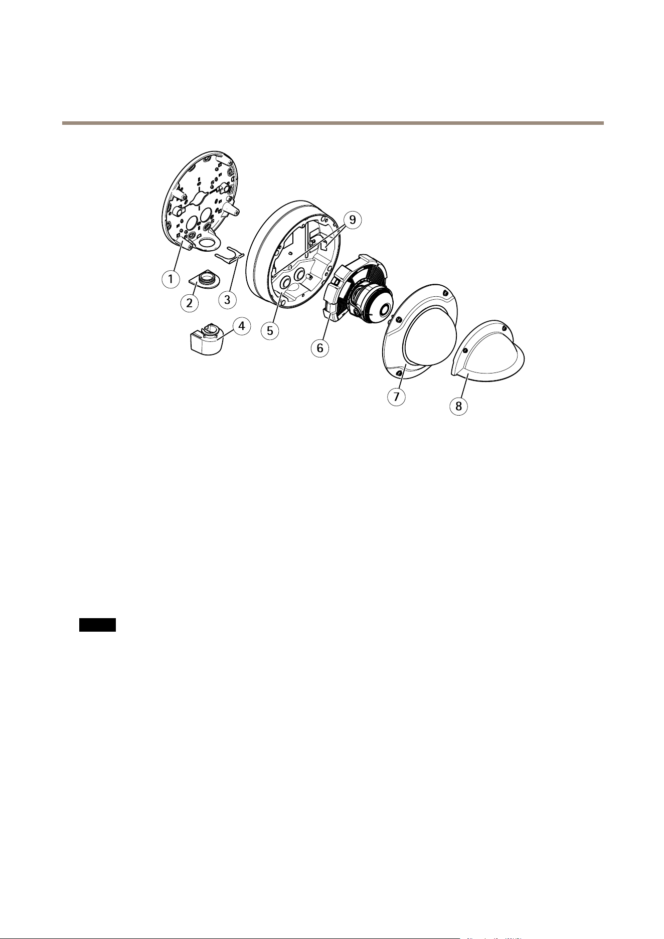
HardwareOverview
1
Mountingbracket
2
Sidelidcoveringsideholeinmountingbracket
3
Lockingclip
4
Conduitadaptor
5
Unitcasing
6
Cameraunit
7
Domecover
8
Weathershield
9
Springs
ConnectorsandButtons
NetworkConnector
RJ45EthernetconnectorwithPoweroverEthernet(PoE).
NO NO
NO
TICE TICE
TICE
Theproductshallbeconnectedusingashieldednetworkcable(STP).Allcablesconnectingtheproducttothenetworkshall
beintendedfortheirspecicuse.Makesurethatthenetworkdevicesareinstalledinaccordancewiththemanufacturer’s
instructions.Forinformationaboutregulatoryrequirements,seeElectromagneticCompatibility(EMC)onpage2.
I/OConnector
Usewithexternaldevicesincombinationwith,forexample,tamperingalarms,motiondetection,eventtriggering,andalarm
notications.Inadditiontothe0VDCreferencepointandpower(DCoutput),theI/Oconnectorprovidestheinterfaceto:
•Digitaloutput–ForconnectingexternaldevicessuchasrelaysandLEDs.Connecteddevicescanbeactivatedbythe
VAPIX®ApplicationProgrammingInterface,outputbuttonsontheLiveViewpageorbyanActionRule.Theoutputwill
showasactive(shownunderSystemOptions>Ports&Devices)ifthealarmdeviceisactivated.
•Digitalinput–Analarminputforconnectingdevicesthatcantogglebetweenanopenandclosedcircuit,forexample:
PIRs,door/windowcontacts,glassbreakdetectors,etc.Whenasignalisreceivedthestatechangesandtheinputbecomes
active(shownunderSystemOptions>Ports&Devices).
8
Loading ...
Loading ...
Loading ...