
Loading ...
Loading ...
Loading ...
Part 1 – Introduction
11
• Alarm in
Connect an alarm-in device to this port. Connect a
mechanical or electrical switch to the IN and GND
(ground) connectors. Alarm in range is 0V to 5V. In
order to detect alarm input from an electrical switch,
the signal must be higher than 4.3V from an NC
switch or less than 0.3V from an NO switch and must
last for longer than 0.5 seconds.
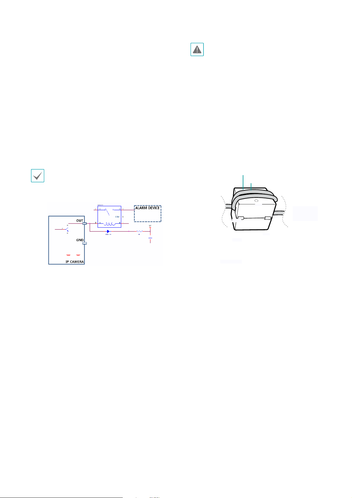
• Alarm Out
It is the BJT (Bipolar Junction Transistor) - open
collector output. If the voltage and current exceed
the specication limit (max. load: 30mA, max.
voltage: 5VDC), the product could be damaged.
When connecting the device which exceeds the
specication limit, refer to the picture (circuit) below
If used with an external inductive load(e.g. relay), a
diode must be connected in parallerl with the load
for protection. Otherwise, the product could be
damaged.
• Check your local laws and regulations on making
video or audio recordings. The user will be held
liable for any violation of the law.
• When switching over from 12 VDC to PoE as the
power source, the system will be rebooted once
the power adapter is disconnected.
• Organize the power cable so that it will not
cause people to trip over or become damaged
from chairs, cabinets, desks, and other objects
in the vicinity. Do not run the power cable
underneath carpet or a rug or plug the cable
into a power outlet shared by a number of other
devices.
• Wrap the camera-end of the network cable
twice around the provided ferrite core to subdue
electromagnetic wave generation.
Ferrite Core
LAN Cable
• The network connector is not designed to be
connected directly with cable or wire intended
for outdoor use.
ALARM
DEVICE
IP CAMERA
GND
OUT
RELAY
DIODE
COM
Loading ...
Loading ...
Loading ...