
Outdoor Fixed LED Display Unit
Quick Start Guide

Outdoor Fixed LED Display Unit Quick Start Guide
i
Legal Information
©2023 Hangzhou Hikvision Digital Technology Co., Ltd. All rights reserved.
About this Manual
The Manual includes instructions for using and managing the Product. Pictures, charts, images and
all other information hereinafter are for description and explanation only. The information
contained in the Manual is subject to change, without notice, due to firmware updates or other
reasons. Please find the latest version of this Manual at the Hikvision website
(https://www.hikvision.com/).
Please use this Manual with the guidance and assistance of professionals trained in supporting the
Product.
Trademarks
and other Hikvision's trademarks and logos are the properties of
Hikvision in various jurisdictions.
Other trademarks and logos mentioned are the properties of their respective owners.
: The terms HDMI and HDMI High-Definition Multimedia Interface, and the HDMI
Logo are trademarks or registered trademarks of HDMI Licensing Administrator, Inc. in the United
States and other countries.
Disclaimer
TO THE MAXIMUM EXTENT PERMITTED BY APPLICABLE LAW, THIS MANUAL AND THE PRODUCT
DESCRIBED, WITH ITS HARDWARE, SOFTWARE AND FIRMWARE, ARE PROVIDED "AS IS" AND
"WITH ALL FAULTS AND ERRORS". HIKVISION MAKES NO WARRANTIES, EXPRESS OR IMPLIED,
INCLUDING WITHOUT LIMITATION, MERCHANTABILITY, SATISFACTORY QUALITY, OR FITNESS FOR
A PARTICULAR PURPOSE. THE USE OF THE PRODUCT BY YOU IS AT YOUR OWN RISK. IN NO EVENT
WILL HIKVISION BE LIABLE TO YOU FOR ANY SPECIAL, CONSEQUENTIAL, INCIDENTAL, OR INDIRECT
DAMAGES, INCLUDING, AMONG OTHERS, DAMAGES FOR LOSS OF BUSINESS PROFITS, BUSINESS
INTERRUPTION, OR LOSS OF DATA, CORRUPTION OF SYSTEMS, OR LOSS OF DOCUMENTATION,
WHETHER BASED ON BREACH OF CONTRACT, TORT (INCLUDING NEGLIGENCE), PRODUCT
LIABILITY, OR OTHERWISE, IN CONNECTION WITH THE USE OF THE PRODUCT, EVEN IF HIKVISION
HAS BEEN ADVISED OF THE POSSIBILITY OF SUCH DAMAGES OR LOSS.
YOU ACKNOWLEDGE THAT THE NATURE OF THE INTERNET PROVIDES FOR INHERENT SECURITY
RISKS, AND HIKVISION SHALL NOT TAKE ANY RESPONSIBILITIES FOR ABNORMAL OPERATION,
PRIVACY LEAKAGE OR OTHER DAMAGES RESULTING FROM CYBER-ATTACK, HACKER ATTACK,
VIRUS INFECTION, OR OTHER INTERNET SECURITY RISKS; HOWEVER, HIKVISION WILL PROVIDE
TIMELY TECHNICAL SUPPORT IF REQUIRED.
YOU AGREE TO USE THIS PRODUCT IN COMPLIANCE WITH ALL APPLICABLE LAWS, AND YOU ARE
SOLELY RESPONSIBLE FOR ENSURING THAT YOUR USE CONFORMS TO THE APPLICABLE LAW.
ESPECIALLY, YOU ARE RESPONSIBLE, FOR USING THIS PRODUCT IN A MANNER THAT DOES NOT
INFRINGE ON THE RIGHTS OF THIRD PARTIES, INCLUDING WITHOUT LIMITATION, RIGHTS OF

Outdoor Fixed LED Display Unit Quick Start Guide
ii
PUBLICITY, INTELLECTUAL PROPERTY RIGHTS, OR DATA PROTECTION AND OTHER PRIVACY RIGHTS.
YOU SHALL NOT USE THIS PRODUCT FOR ANY PROHIBITED END-USES, INCLUDING THE
DEVELOPMENT OR PRODUCTION OF WEAPONS OF MASS DESTRUCTION, THE DEVELOPMENT OR
PRODUCTION OF CHEMICAL OR BIOLOGICAL WEAPONS, ANY ACTIVITIES IN THE CONTEXT RELATED
TO ANY NUCLEAR EXPLOSIVE OR UNSAFE NUCLEAR FUEL-CYCLE, OR IN SUPPORT OF HUMAN
RIGHTS ABUSES.
IN THE EVENT OF ANY CONFLICTS BETWEEN THIS MANUAL AND THE APPLICABLE LAW, THE
LATTER PREVAILS.
Outdoor Fixed LED Display Unit Quick Start Guide
i
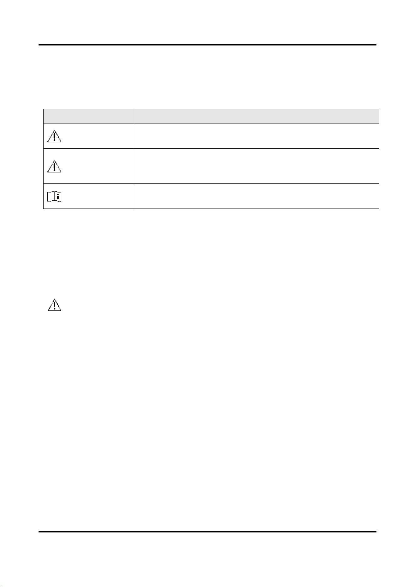
Symbol Conventions
The symbols that may be found in this document are defined as follows.
Symbol
Description
Danger
Indicates a hazardous situation which, if not avoided, will or could
result in death or serious injury.
Caution
Indicates a potentially hazardous situation which, if not avoided,
could result in equipment damage, data loss, performance
degradation, or unexpected results.
Note
Provides additional information to emphasize or supplement
important points of the main text.
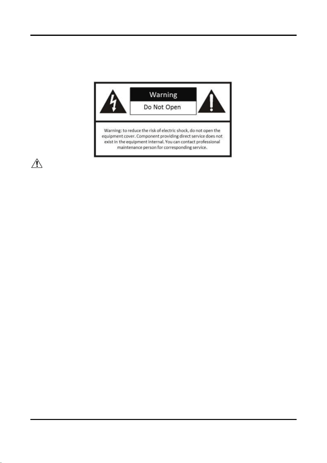
Safety Instruction
For safety concerns, the device has been strictly tested before shipment. However, incorrect
installation or usage may lead to hazardous results such as electric shock and fire. To ensure the
service life and best performance of the device, please read the notice and plate signs carefully
and follow the safety instructions. Keep this guide properly for later use.
Caution
● To ensure safety, the installation parts and the wall should support four times the weight of the
device.
● Install the device no more than 5 mm away from the wall or other metal racks in case of lamp
board drop resulting in electric shock.
● Please set the brightness of the LED display within 500 nits to avoid power overload.
● The device may generate radio interference in indoor environment. Necessary precautions may
be required.
● To reduce the risk of fire or electric shock, please do not expose the device to rain or humid
environment.
● Electric discharge may last for a short period of time after the power is shut down. Please wait
two minutes after the power is shut down before operating the device.
● To avoid the risk of electric shock, please do not operate when the power is on.
● Please do not plug and unplug the power cable when the power is on.
● Ensure the correct wire sequence of the terminals connected to the AC power supply.
● Do not place anything containing liquid on the device to avoid the risk of fire or electric shock
caused by liquid-splashing.
● The device is only suitable for installation on the concrete or non-flammable surfaces, to
prevent molten material from dripping to the bottom during fire caused by internal failure.
● Keep 90 degrees when moving and using the device.
Outdoor Fixed LED Display Unit Quick Start Guide
ii
● After installation, there should be no openings around the LED module. The bottom bracket
under the wire outlet position should completely cover the bottom hole only to let the wire out,
to prevent the molten material from dripping to the bottom during fire caused by internal
failure.
Warning
● In the use of the product, you must be in strict compliance with the electrical safety regulations
of the nation and region.
● Disconnect the power plug before maintenance.
● Make sure the power supply is well-grounded.
● The protective grounding of the device should be reliably connected to the building protective
grounding.
● To reduce the risk of electric shock, install protective shield on the exposed connector after
installing LED screen.
● Disconnect the power plug before installing the protective shield.
● A disconnecting device should be provided on the outside of the equipment. A single device is
recommended for AC 220 V / 230 V / 240 V, 6 A circuit breakers. When multiple devices are
superimposed, a suitable circuit breaker should be selected according to the total rated current,
but it must not exceed the building equipped circuit specifications.
● To prevent injury, the device must be securely fixed to the ground, wall, ceiling, or steel frame.
The all-in-one rack should be fixed to the ground with expansion screws.
● The supporting rack can only be used with the device. Using it with other devices may cause
instability and injury.
● The device can only be used with the supporting rack. Using it with other equipment (such as a
cart, shelf, or handling device) may cause instability and injury.
● Please strictly follow the installation method in this guide.
● The external wire connection between device and hazardous electronic terminals should be
operated by professionals.
● This is a class A product and may cause radio interference in which case the user may be
required to take adequate measures.

Outdoor Fixed LED Display Unit Quick Start Guide
iii
Contents
Chapter 1 Product Introduction .................................................................................................. 1
1.1 Overview ................................................................................................................................ 1
1.2 Product Components............................................................................................................. 1
Chapter 2 Cabinet Installation .................................................................................................... 2
2.1 Introduction ........................................................................................................................... 2
2.1.1 About Cabinet ............................................................................................................. 2
2.1.2 Load Capability of Cabinet ......................................................................................... 2
2.1.3 Cabinet Overview ....................................................................................................... 3
2.2 Install Cabinet ........................................................................................................................ 5
2.2.1 Precautions ................................................................................................................. 5
2.2.2 Stitch Cabinet Frames ................................................................................................ 5
2.3 Connect Power Cord and Network Cable ............................................................................. 9
2.3.1 Connect Power Cord ................................................................................................... 9
2.3.2 Connect Network Cable ........................................................................................... 15
2.4 Maintenance ........................................................................................................................ 19
2.4.1 Maintain Lamp Board ............................................................................................... 19
2.4.2 Maintain Power Supply Box ..................................................................................... 23
Chapter 3 Software Debugging ................................................................................................. 26
Appendix FAQ ............................................................................................................................ 1

Outdoor Fixed LED Display Unit Quick Start Guide
1
Chapter 1 Product Introduction
1.1 Overview
Outdoor fixed LED display unit (hereinafter referred to as the device, the product, or the LED) is a
new generation of full-color fine pitch outdoor LED display unit. It adopts aluminum profile
cabinets with concise appearance. The heat dissipation performance of the whole device is
highly improved with aluminum modules. It features in IP66 protection level, guaranteeing
the normal running in various severe environments. The highest brightness reaches 6000 to
guarantee the display effect even in high brightness regions. It is applicable to various
scenarios such as the outdoor billboards, outdoor walls, and roofs.
1.2 Product Components
An LED control system includes sending and receiving cards. The sending card packages images
and sends them to the receiving card. The receiving card unpackages and processes the images,
and then displays the images on the LED display unit.
The pixel pitch is the distance in millimeters from the center of a pixel to the center of the
adjacent pixel. The smaller pixel pitch equates to higher pixel density per unit area, higher
resolution and higher cost. P1.2 indicates 1.2 mm pixel pitch.
Outdoor Fixed LED Display Unit Quick Start Guide
2
Chapter 2 Cabinet Installation
2.1 Introduction
2.1.1 About Cabinet
A cabinet is a basic unit for LED engineering installation in which LED modules are neatly mounted
on a metal sheet (cast aluminum) box, with a built-in independent receiving card and switching
power supply, an engineering installation structure, and independent display.
2.1.2 Load Capability of Cabinet
Load Capability of Power Cords
The load capability of a single power cord is limited. You can calculate the max load of a single
power cord by the following formula.
Max Load of a Single Power cord = Power of the Cord/Power of the Cabinet
Note
You can choose power cords and cabinets of different specifications, and calculate the load
capability by the formula.
Load Capability of Network Interfaces
The load capability of a single network interface of the sending card is limited. You can calculate
the max load of a single network interface by the following formula.
Max Load of a Network Interface = Pixel Capacity of a Network Interface/Cabinet Resolution
Example
If equipped with a sending card of 650,000 pixels, the max load of a single network interface for a
P1.2 cabinet of 480 × 270 resolution is 5 cabinets.
Note
You can choose sending cards of different pixels and cabinets of different resolution, and
calculate the load capability by the formula.
Outdoor Fixed LED Display Unit Quick Start Guide
3
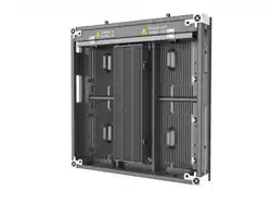
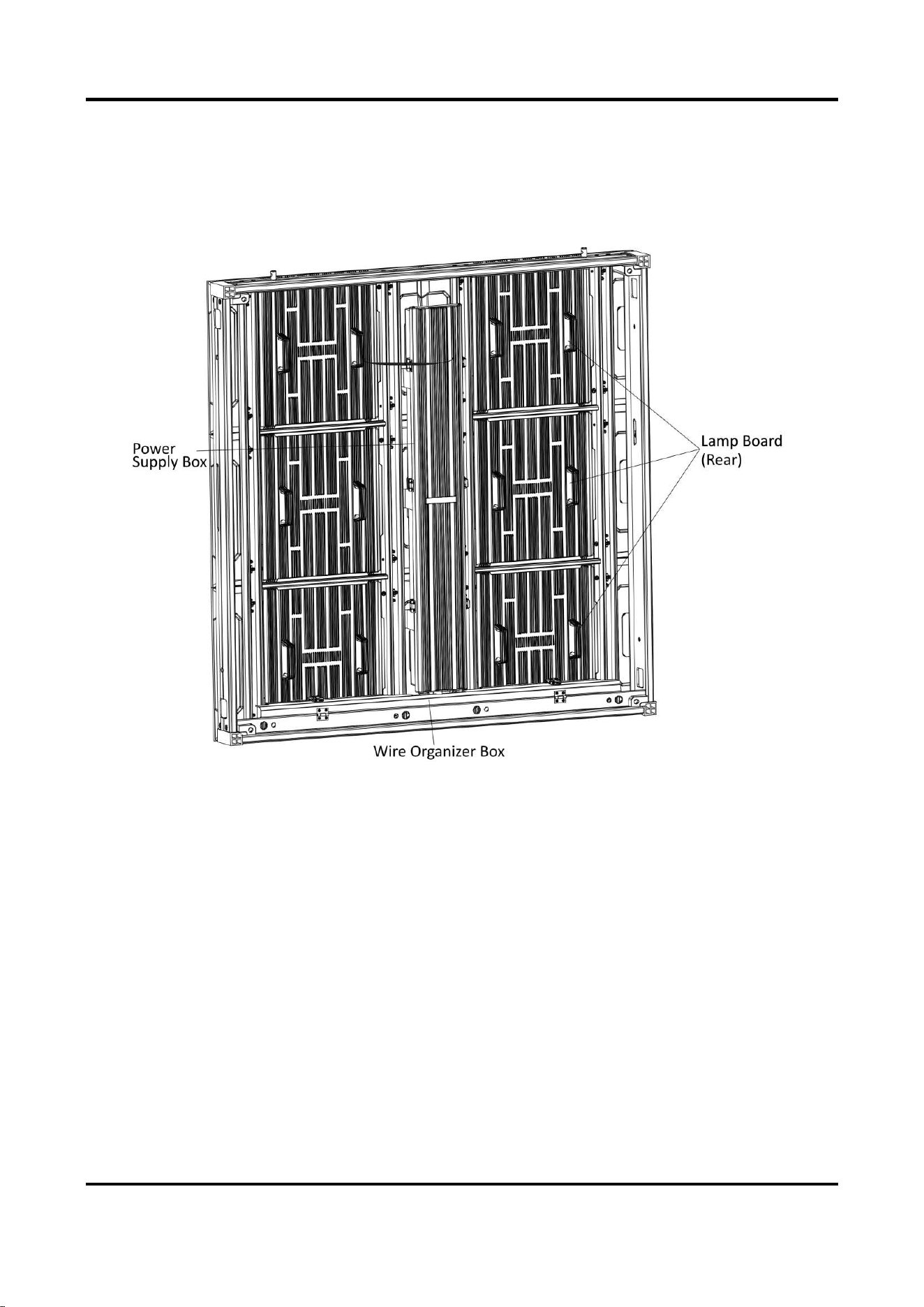
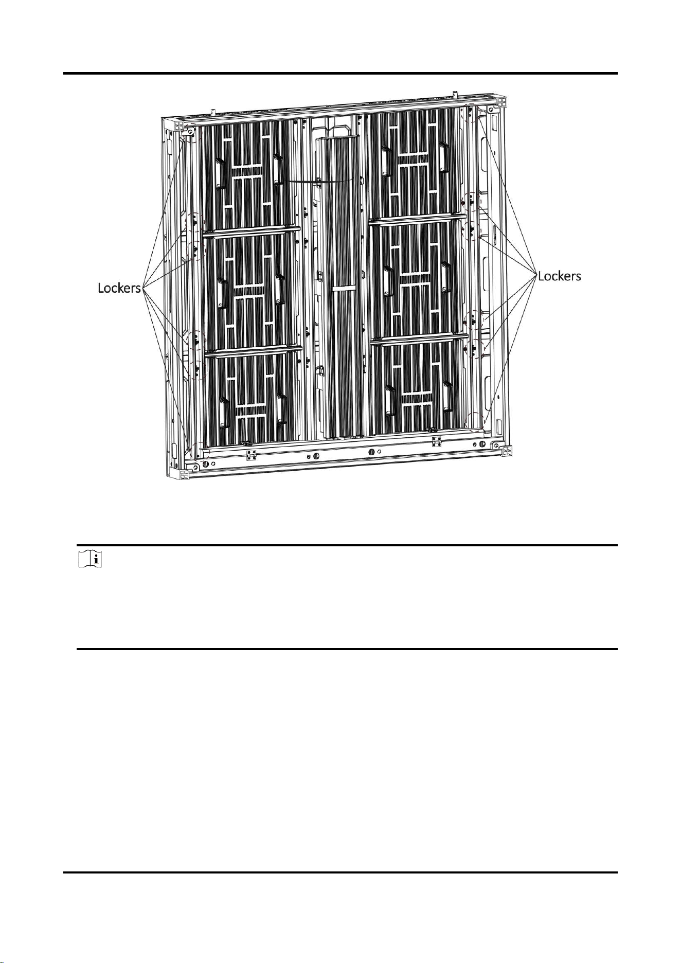
2.1.3 Cabinet Overview
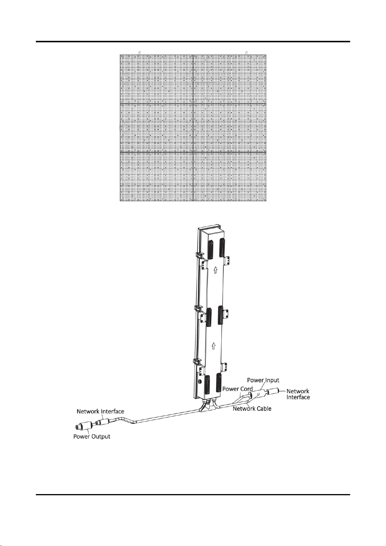
Each cabinet is equipped with a power supply box. The power cord and network cable are already
connected with the power supply box and hidden in the wire organizer box after the device leaves
factory.
Figure 2-1 Cabinet Overview (Rear)
Outdoor Fixed LED Display Unit Quick Start Guide
4
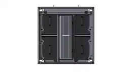
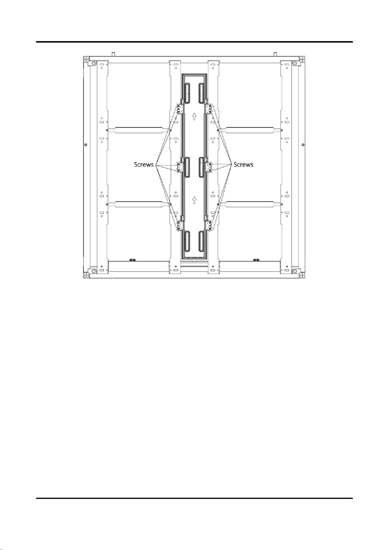
Figure 2-2 Cabinet Overview (Front)
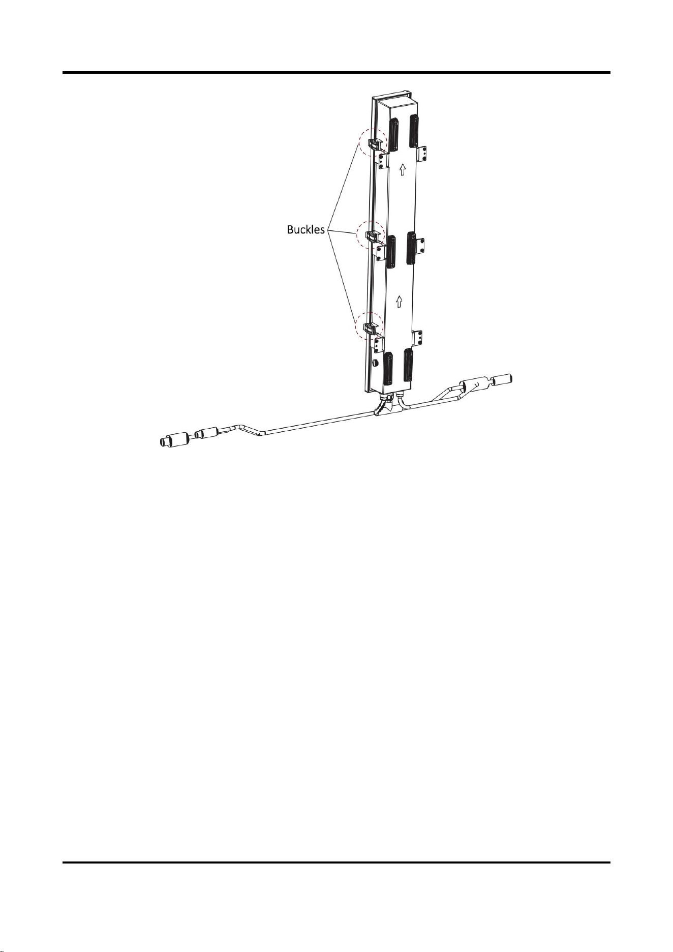
Figure 2-3 Power Supply Box Overview

Outdoor Fixed LED Display Unit Quick Start Guide
5
Note
The figures are for reference only. The actual device prevails.
2.2 Install Cabinet
2.2.1 Precautions
Read the following precautions before you install the device:
● Electric discharge may last for a short period of time after the power is shut down. Please wait
two minutes after the power is shut down to operate the device.
● Only use the original power cord delivered with the device. Contact authorized dealer to
purchase power cord with same specifications.
● Please do not frequently plug or unplug the power cord when the power is on.
2.2.2 Stitch Cabinet Frames
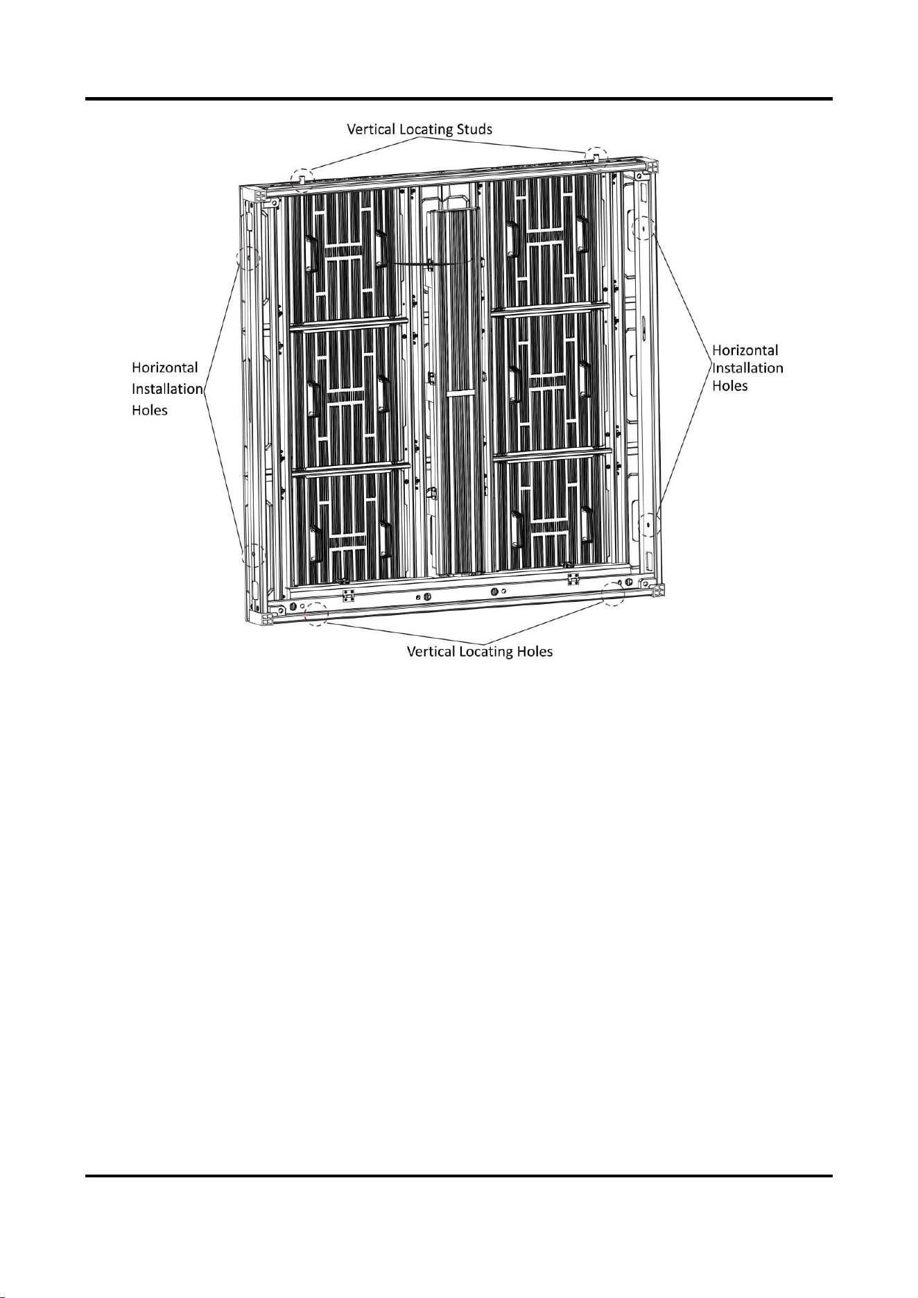
Cabinet Frame Locating
Align two cabinet frames with the locating studs, locating holes, and installation holes. Each
cabinet frame is equipped with two vertical locating studs, two vertical locating holes, and two
sets of horizontal installation holes.
Outdoor Fixed LED Display Unit Quick Start Guide
6
Figure 2-4 Cabinet Frame Locating
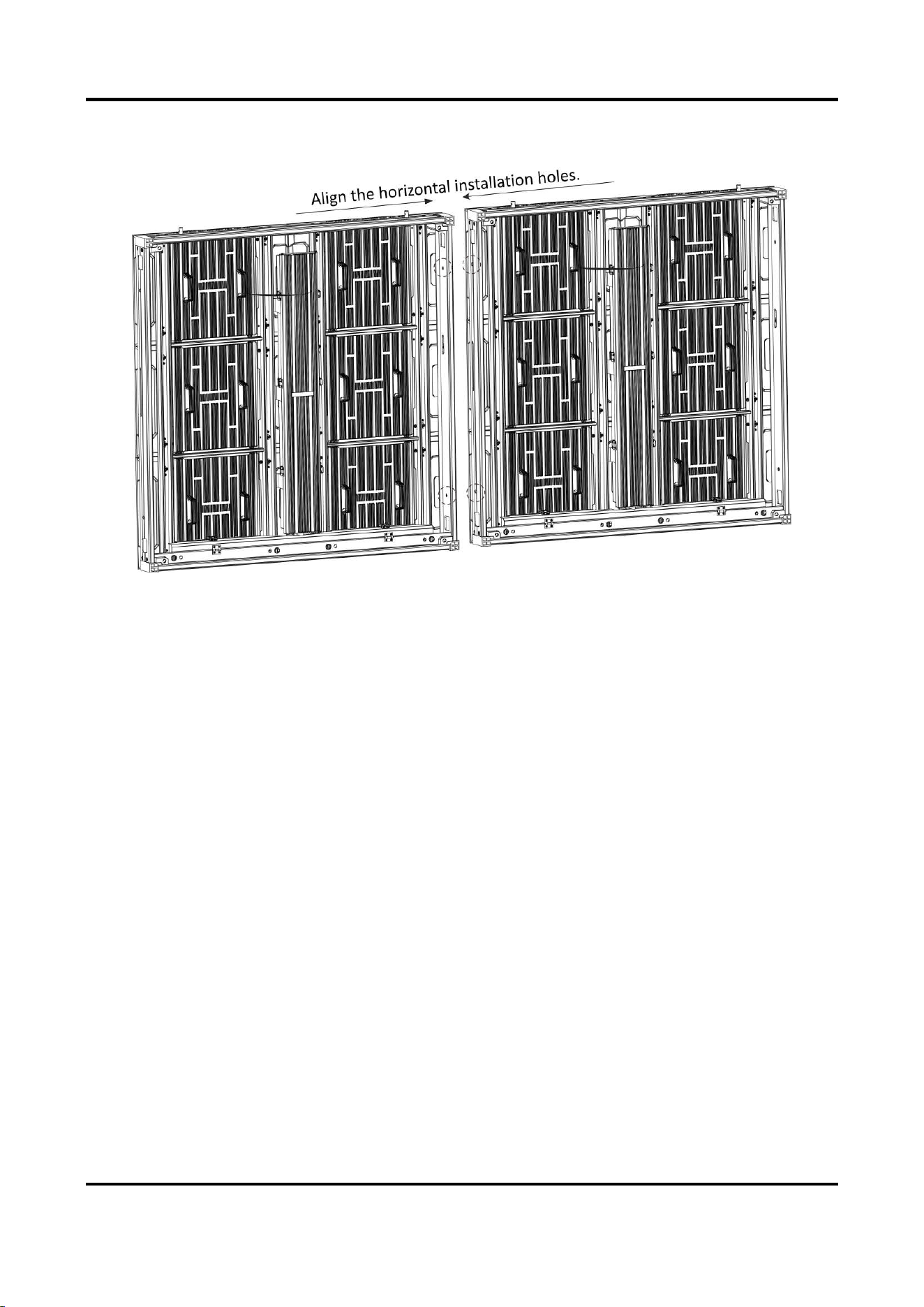
Stitch Cabinet Frames Horizontally
Steps
1. Align the installation holes in the horizontal direction of the two adjacent cabinet frames, and
adjust the cabinet frames to the relative height.
Outdoor Fixed LED Display Unit Quick Start Guide
7
2. Insert two M10 hex screws into the installation holes, and fasten the screws with nuts.
Figure 2-5 Stitch Cabinet Frames Horizontally
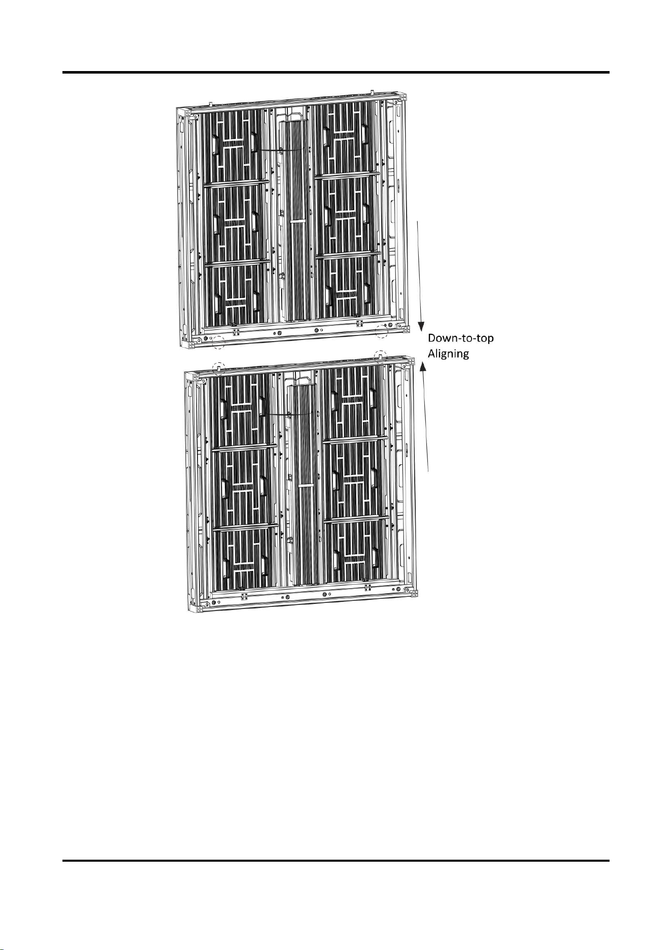
Stitch Cabinet Frames Vertically
Align the locating studs in the vertical direction of the two adjacent cabinet frames to the locating
holes, and adjust the cabinet frames vertically against each other.
Outdoor Fixed LED Display Unit Quick Start Guide
8
Figure 2-6 Stitch Cabinet Frames Vertically
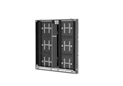
After the horizontal and vertical stitching, a complete LED display unit is stitched.
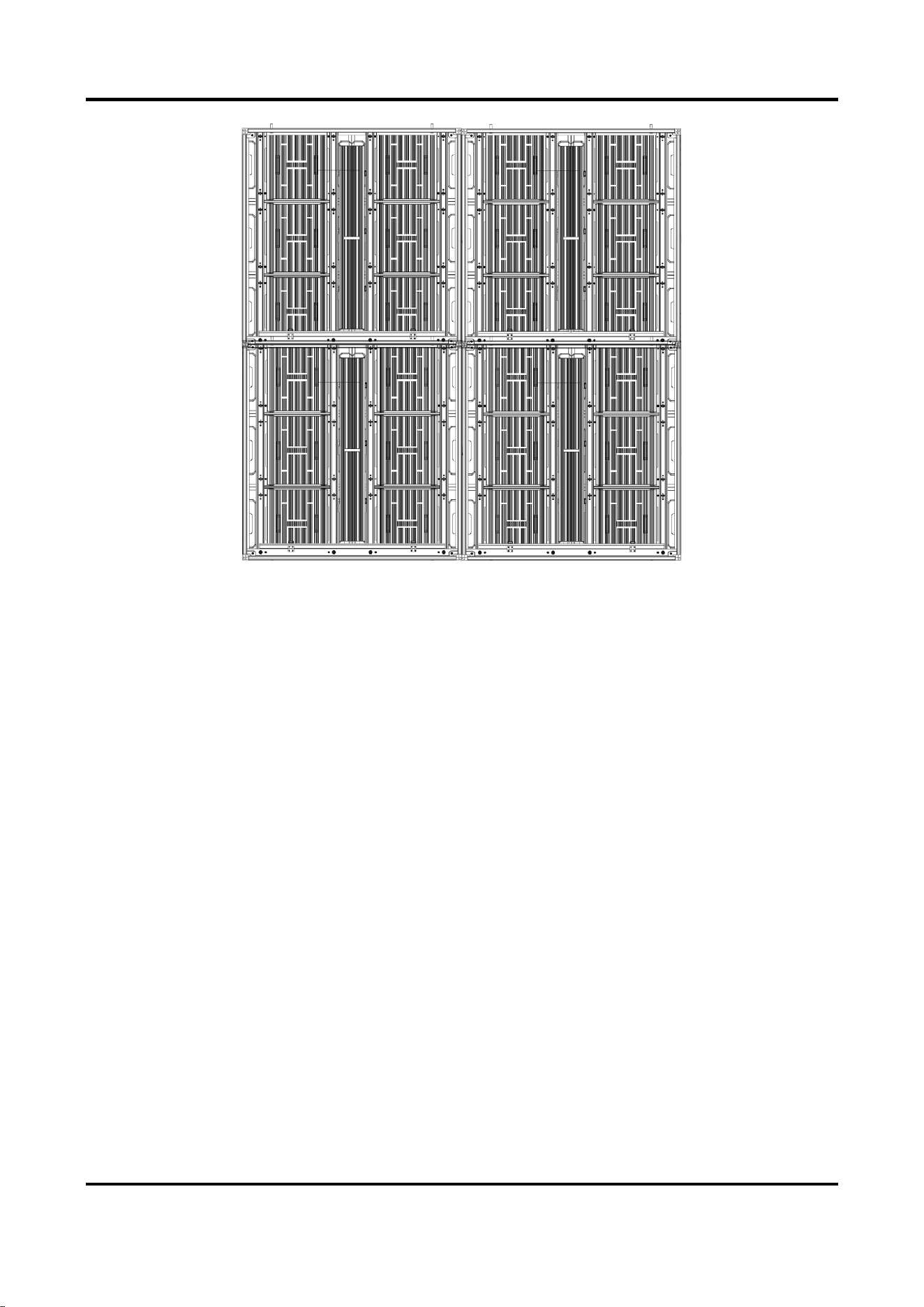
Outdoor Fixed LED Display Unit Quick Start Guide
9
Figure 2-7 Stitched LED Display Unit (2 × 2 for Example)
2.3 Connect Power Cord and Network Cable
2.3.1 Connect Power Cord
Each cabinet is equipped with a power input cord and a power output cord in it. The internal
power cords can be connected in cascade in each row, and the external power cords are needed
according to the load capacity of the external power cords.
Steps
1. Unlock the two buckles on the wire organizer box to open it for each cabinet.
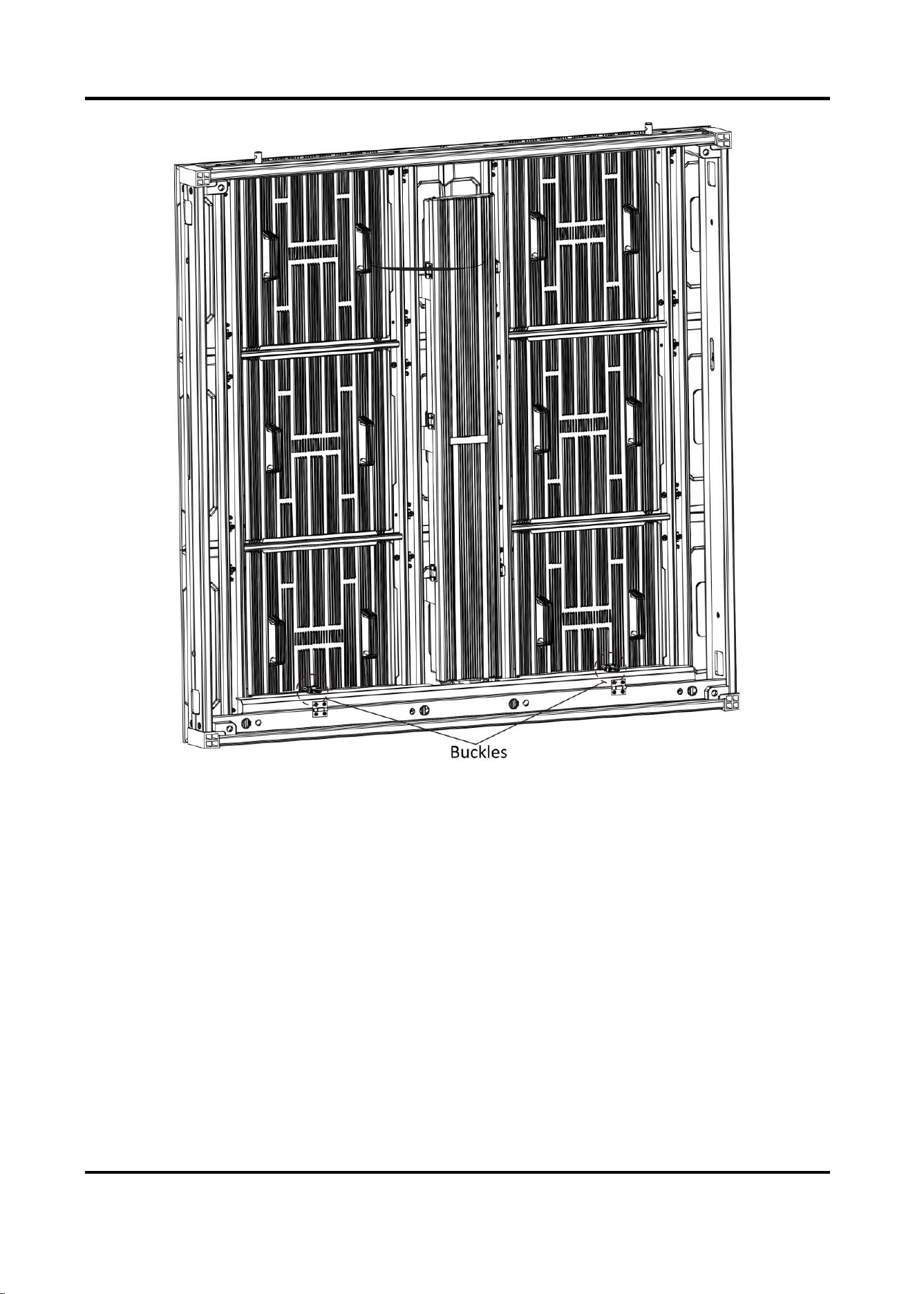
Outdoor Fixed LED Display Unit Quick Start Guide
10
Figure 2-8 Open Wire Organizer Box
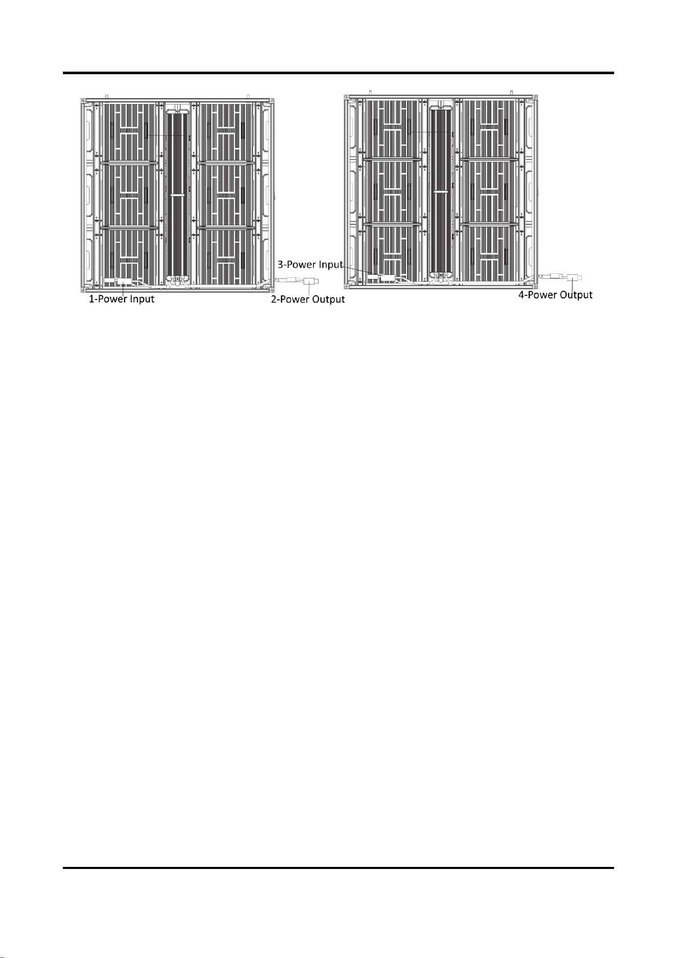
2. Connect the external power supply to the power input interface of the first cabinet in each
row.
3. Connect the internal power cords within the max load. Connect the power output interface of
one cabinet to the power input interface of the adjacent cabinet horizontally through the
wiring holes in each row.
As the figure shown below, the left cabinet is the first cabinet in the row. Connect the external
power supply to Interface 1, connect Interface 2 to 3, and connect Interface 4 to another
power input interface of another cabinet in the row.
Outdoor Fixed LED Display Unit Quick Start Guide
11
Figure 2-9 Connect Power Cord
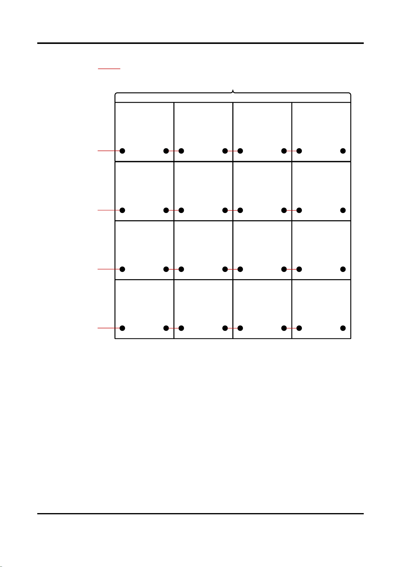
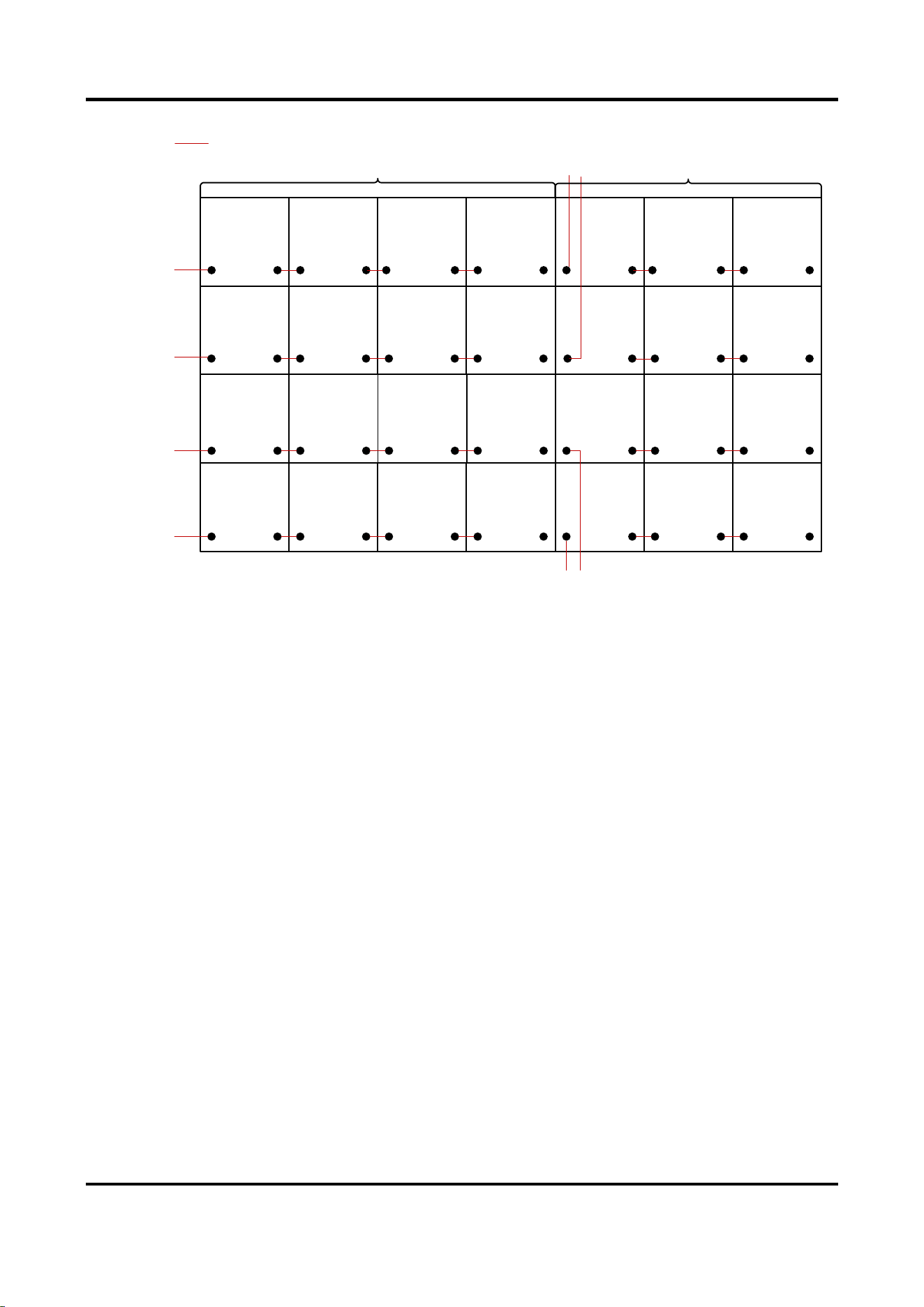
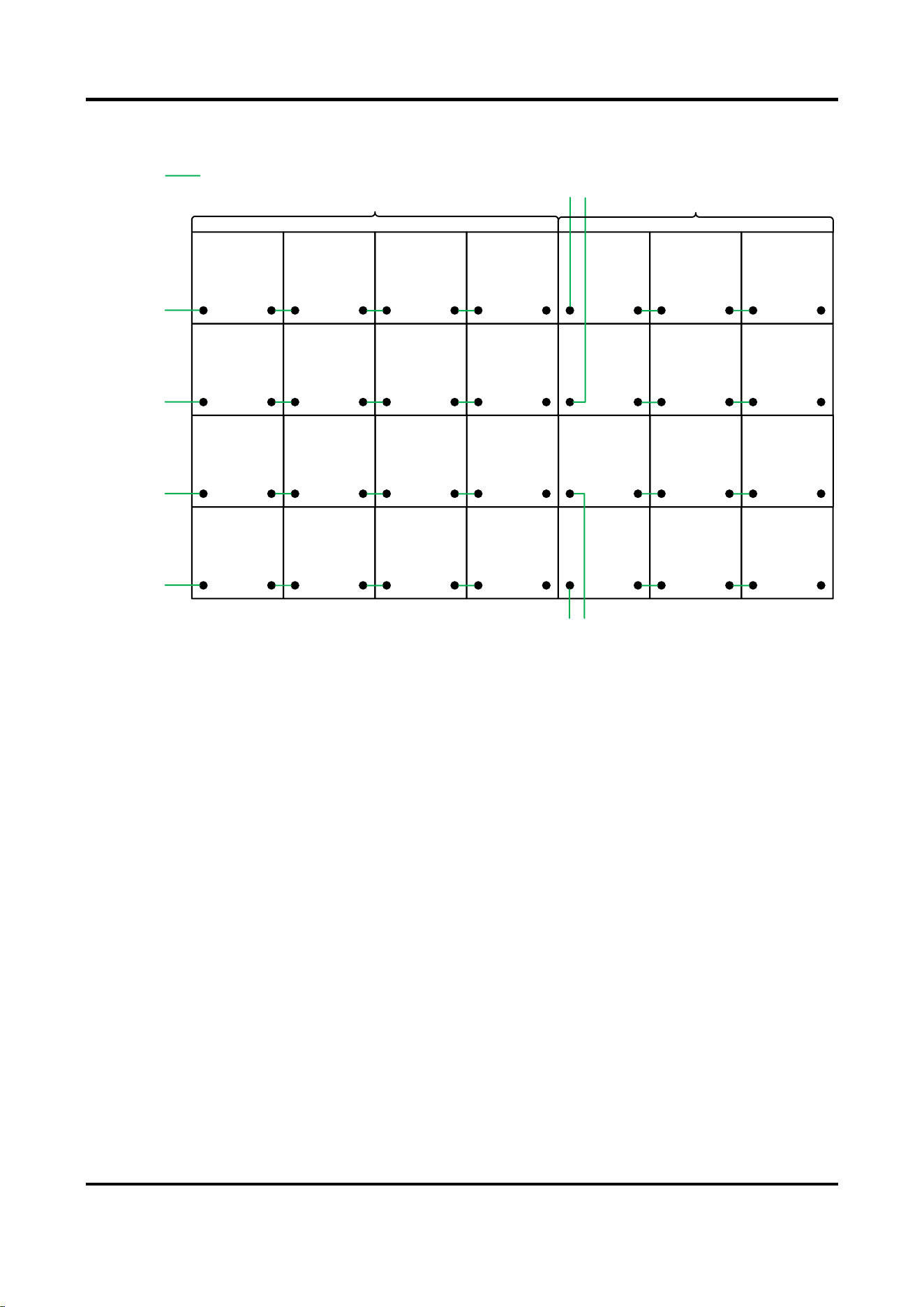
4. (Optional) If the actual number of cabinets exceeds the max load of the power cord, connect
the power input interface of the overloaded cabinet in each row to another external power
cord through the wiring holes.
The figures below take 4 × 4 cabinets (within the max. load of the power cord) and 4 × 7
cabinets (4 × 4 within the max. load and 4 × 3 beyond the max. load of the power cord) for
example.
Outdoor Fixed LED Display Unit Quick Start Guide
12
Power Input 1
Within
Max.
Load
Power Cord
Power Input 2
Power Input 3
Power Input 4
Figure 2-10 Power Cord Connection Diagram (Within Max. Load)
Outdoor Fixed LED Display Unit Quick Start Guide
13
Power
Input 1
Power
Input 2
Power
Input 3
Power
Input 4
Power
Input 5
Power
Input 6
Power
Input 7
Power
Input 8
Within
Max.
Load
Beyond
Max.
Load
Power Cord
Figure 2-11 Power Cord Connection Diagram (Beyond Max. Load)
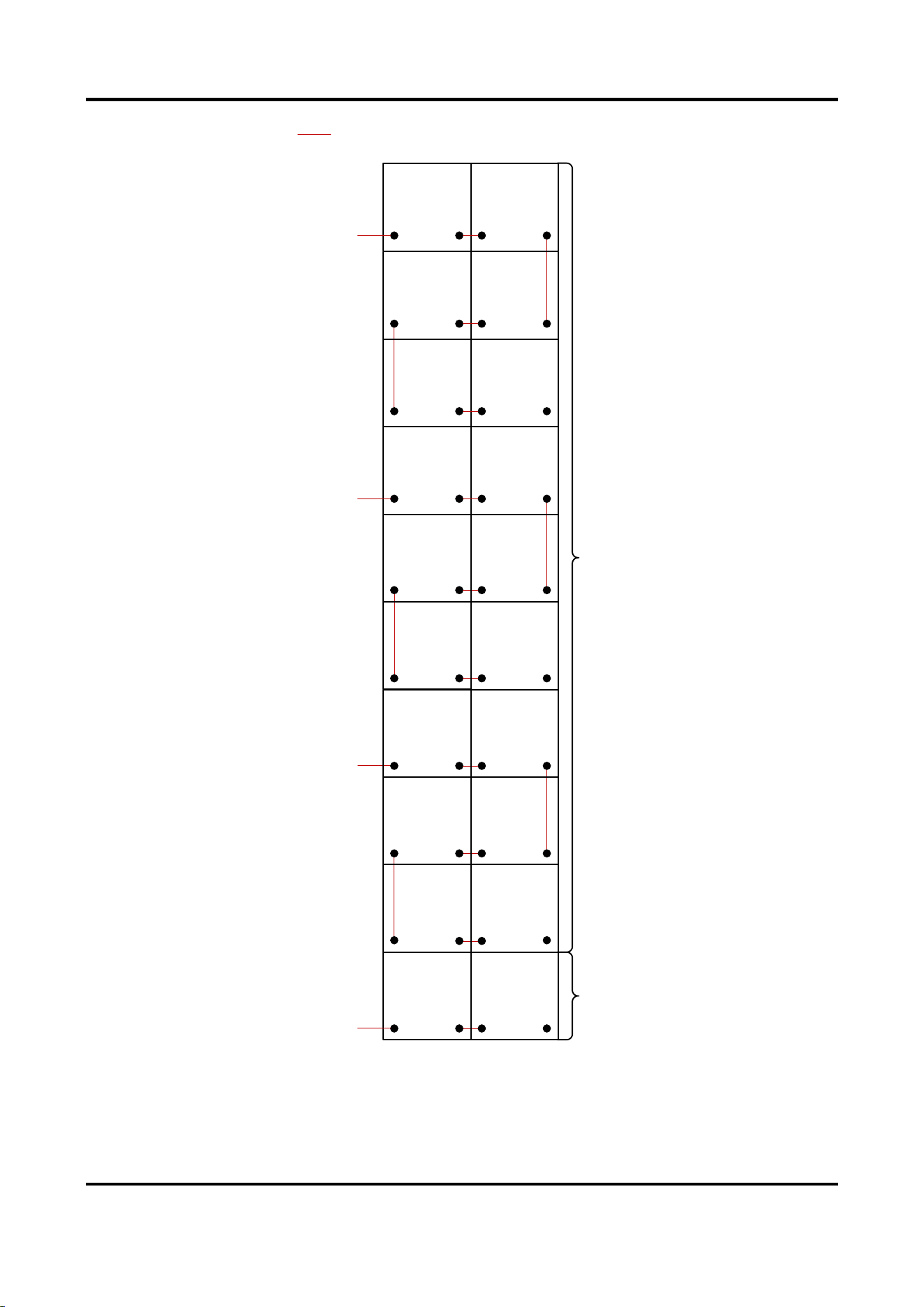
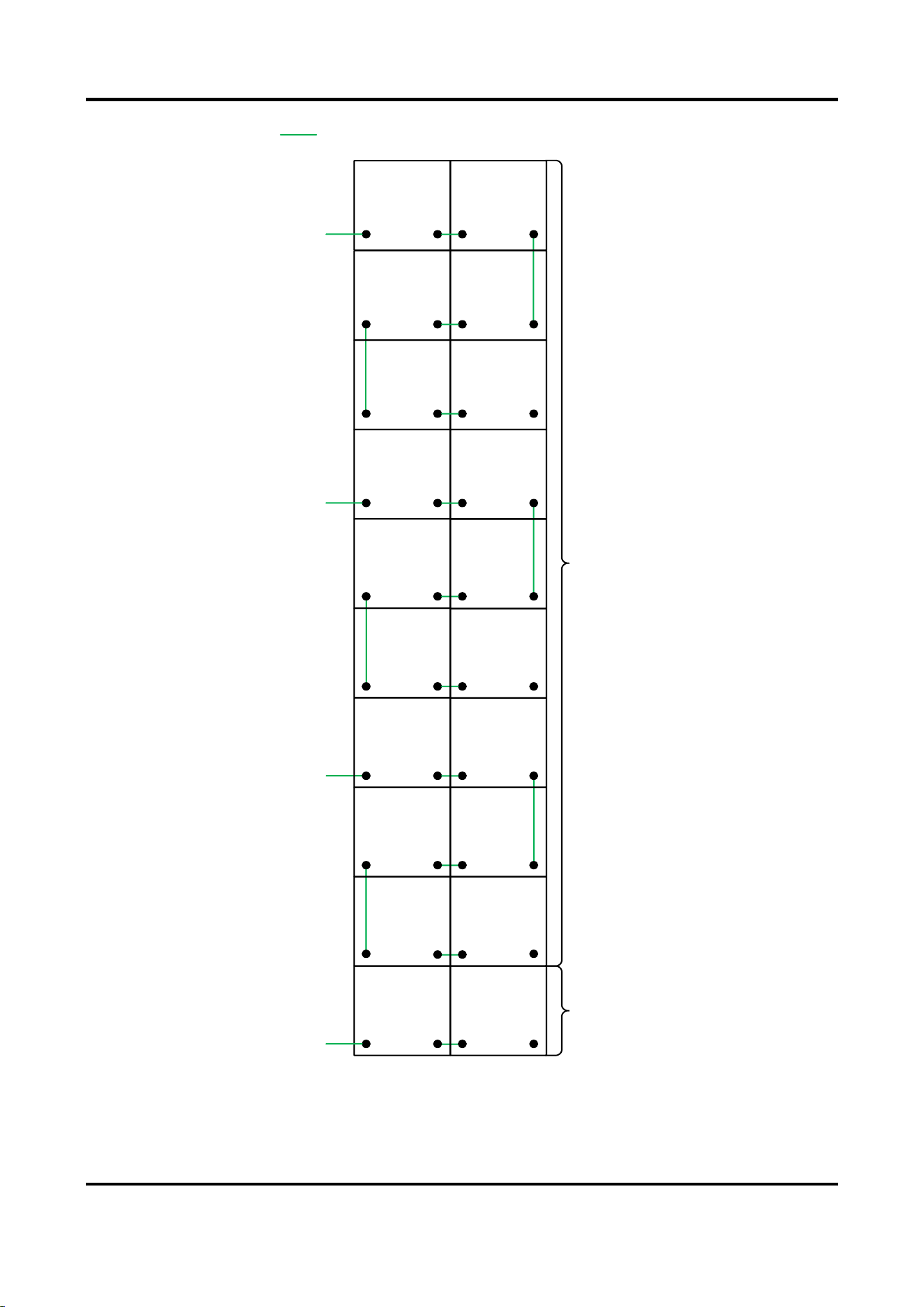
You can also connect the power output interface of one cabinet to the power input interface
of the adjacent cabinet vertically. The figure below takes power cords of load capacity of 6
cabinets for example.
Outdoor Fixed LED Display Unit Quick Start Guide
14
Power Input 1
Power Cord
Power Input 3
Power Input 2
Power Input 4
Within
Max.
Load
Beyond
Max.
Load
Figure 2-12 Power Cord Connection Diagram (Vertical)
5. Lock the two buckles on the wire organizer box to lock it for each cabinet.
Outdoor Fixed LED Display Unit Quick Start Guide
15
2.3.2 Connect Network Cable
Each cabinet is equipped with a network input cable and a network output cable internally. The
internal network cables can be connected in cascade in each row, and the external network cables
for sending card connections are needed according to the load capacity of the network interfaces
of the sending card.
Steps
1. Unlock the two buckles on the wire organizer box of each cabinet.
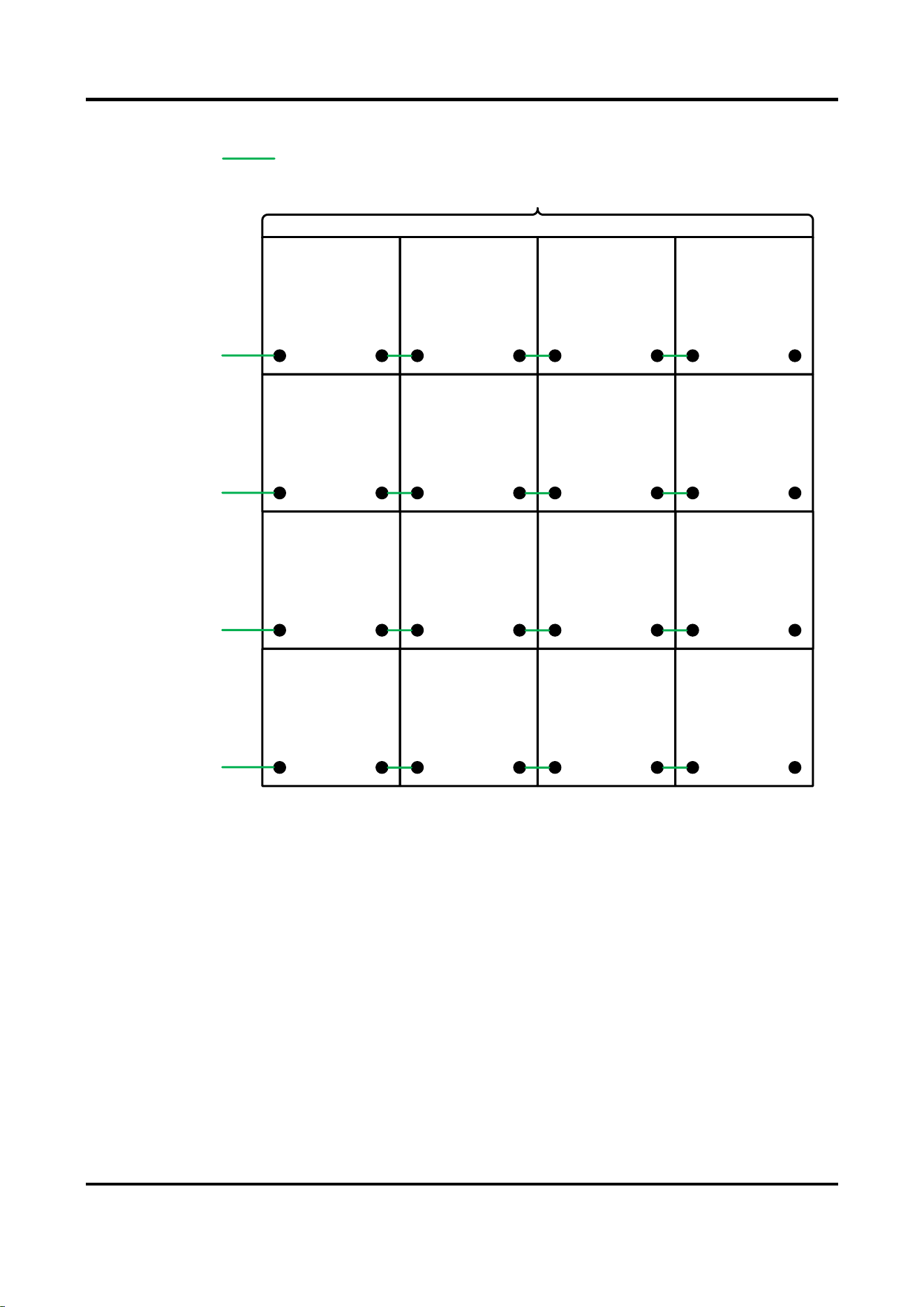
2. Connect the network interface of the first cabinet in each row to the network interface of the
sending card through the wiring holes.
3. Connect the internal network cables within the max load. Connect the network interface of
one cabinet to the network interface of the adjacent cabinet horizontally through the wiring
holes in each row.
Figure 2-13 Connect Network Cable
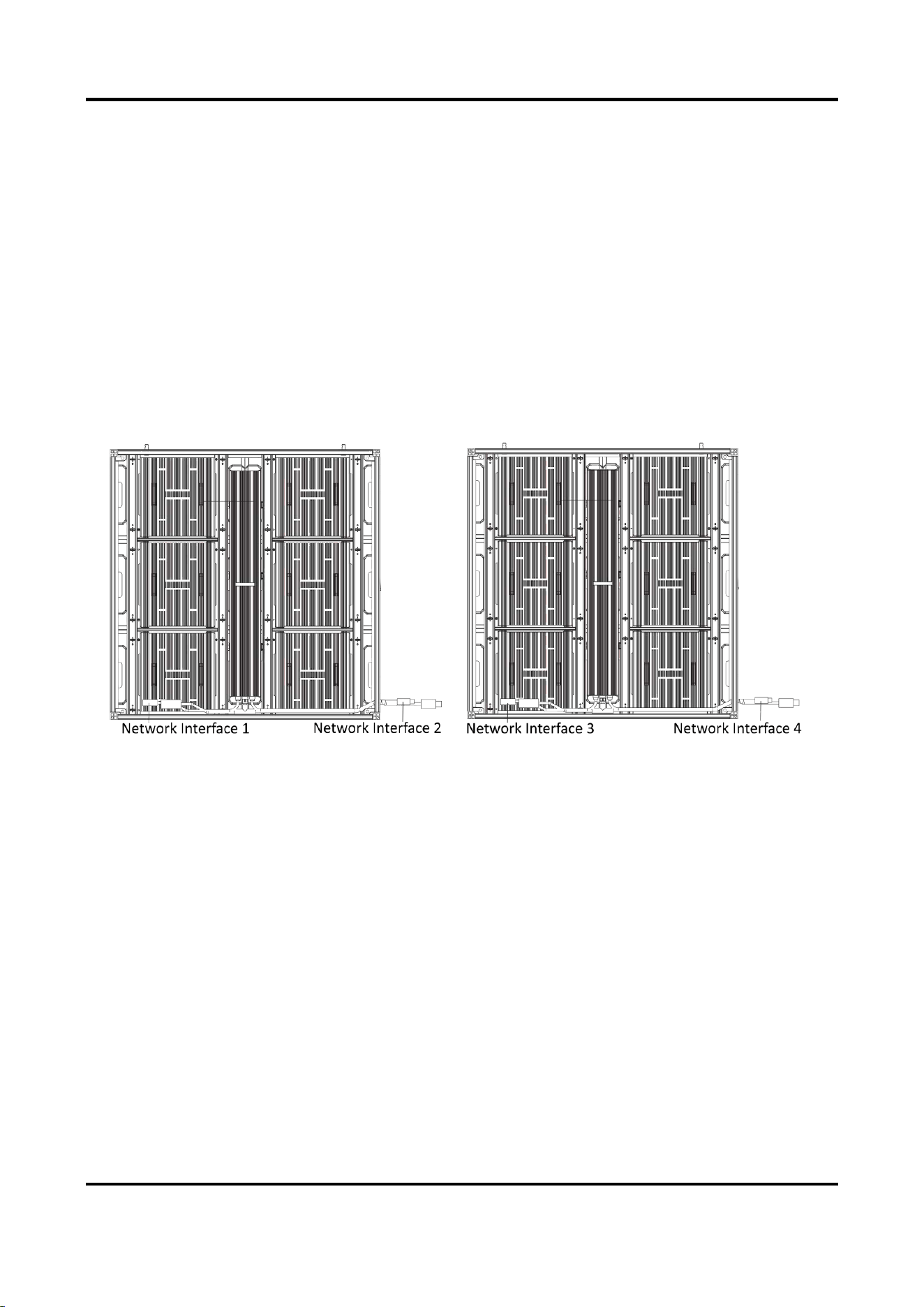
4. (Optional) If the actual number of cabinets exceeds the max load of the network interface,
connect the network interface of the overloaded cabinet in each row to another network
interface of the sending card via an external network cable through the wiring holes.
The figures below take 4 × 4 cabinets (within the max. load of the network cable) and 4 × 7
cabinets (4 × 4 within the max. load and 4 × 3 beyond the max. load of the power cord) for
example.
Outdoor Fixed LED Display Unit Quick Start Guide
16
Sending Card
Network
Interface 1
Sending Card
Network
Interface 2
Sending Card
Network
Interface 3
Sending Card
Network
Interface 4
Within
Max.
Load
Network Cable
Figure 2-14 Network Cable Connection (Within Max. Load)
Outdoor Fixed LED Display Unit Quick Start Guide
17
Sending
Card
Network
Interface 1
Sending
Card
Network
Interface 2
Sending
Card
Network
Interface 3
Sending
Card
Network
Interface 4
Sending
Card
Network
Interface 5
Sending
Card
Network
Interface 6
Sending Card
Network
Interface 7
Sending Card
Network
Interface 8
Within
Max.
Load
Beyond
Max.
Load
Network Cable
Figure 2-15 Network Cable Connection (Beyond Max. Load)
You can also connect the network interface of one cabinet to that of the adjacent cabinet
vertically. The figure below takes network cables of load capacity of 6 cabinets for example.
Outdoor Fixed LED Display Unit Quick Start Guide
18
Sending Card
Network
Interface 1
Network Cable
Sending Card
Network
Interface 3
Sending Card
Network
Interface 2
Sending Card
Network
Interface 4
Within
Max.
Load
Beyond
Max.
Load
Figure 2-16 Network Cable Connection (Vertical)
5. Lock the two buckles on the wire organizer box of each cabinet.

Outdoor Fixed LED Display Unit Quick Start Guide
19
Note
The figures shown above are for reference. The actual connection can be flexibly adjusted
according to your needs, so long as every single network interface is not overloaded.
2.4 Maintenance
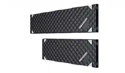
2.4.1 Maintain Lamp Board
You can maintain the lamp boards from the front or rear side.
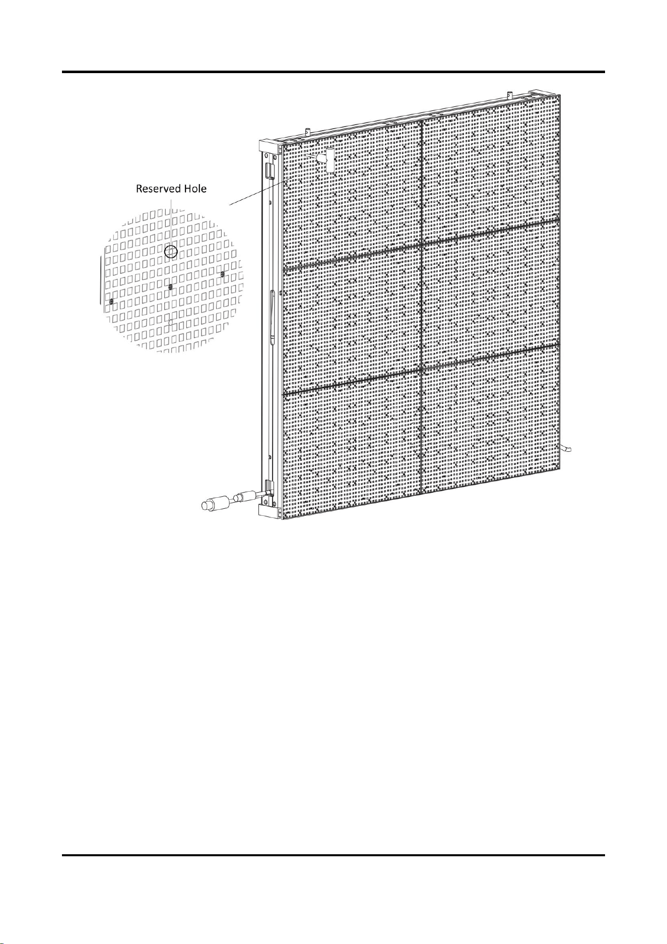
Front Maintenance
Steps:
1. Insert a hex wrench to the reserved hole on the front of the lamp board, and rotate it 90° to
the horizontal direction to unlock the locker on the rear of the lamp board.
Outdoor Fixed LED Display Unit Quick Start Guide
20
Figure 2-17 Disassemble Lamp Board with Hex Wrench
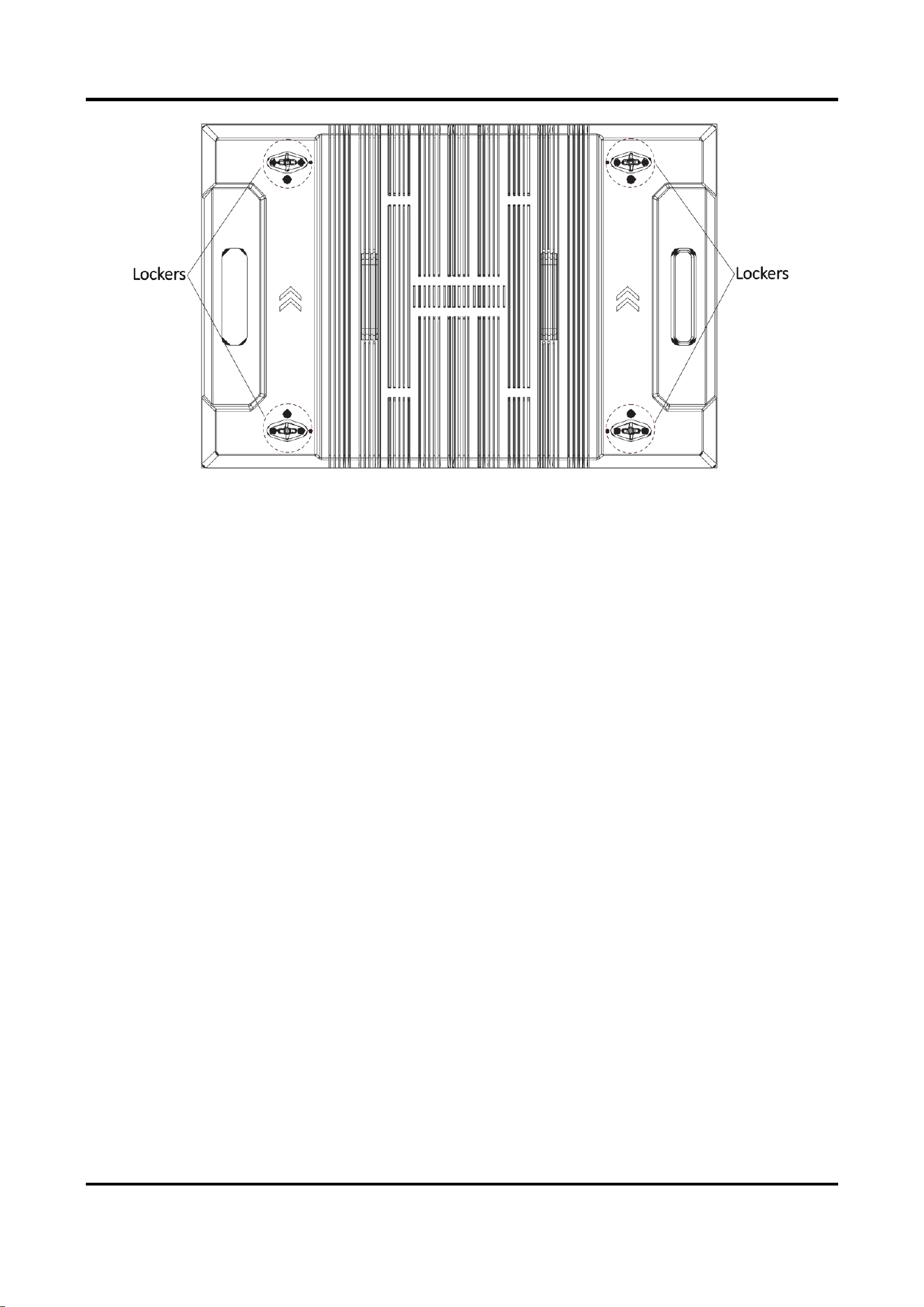
2. Unlock other three lockers of each lamp board.
Outdoor Fixed LED Display Unit Quick Start Guide
21
Figure 2-18 Lamp Board Rear View
3. Pull out the lamp board with force.
4. Repeat the steps above to disassemble other lamp boards.
5. After the maintenance, assemble the lamp boards back.
1) Rotate the four lockers on the rear of the lamp board to the horizontal direction.
2) According to the arrow direction on the rear of the lamp board, align the lockers on the
rear of the lamp board to the reserved spaces on the cabinet frame, and install the lamp
board slowly.
3) Insert a hex wrench to the reserved holes on the front of the lamp board, and rotate it 90°
to the vertical direction to lock the lockers.
4) Repeat the steps above to assemble other lamp boards.
Outdoor Fixed LED Display Unit Quick Start Guide
22
Figure 2-19 Assemble Lamp Board Back
Rear Maintenance
Note
For the upper-level lamp board maintenance, follow the steps to disassemble the lower-level
lamp boards first, and then disassemble the upper-level lamp boards and detach them from
the lower-level cabinet frames to maintain. After the maintenance, follow the steps to
assemble the upper-level lamp boards first, and then assemble the lower-level lamp boards.
Steps:
1. Rotate the four lockers of the lamp board on the rear of the cabinet 90° to the horizontal
direction to unlock them.
2. Hold the handles on the rear of the lamp board and push it out.
3. Turn the lamp board until its short side can go through the frame diagonally.
4. After the lamp board is detached from the frame, unfasten the safety buckle and remove the
lamp board.
5. After the maintenance, assemble the lamp boards back.
1) Rotate the four lockers on the rear of the lamp board to the horizontal direction.

Outdoor Fixed LED Display Unit Quick Start Guide
23
2) Fasten the safety buckle, put the short side of the lamp board diagonally through the
frame, and turn the board until the arrow sign points up.
3) Hold the handles, and align the lockers and locating studs on the rear of the lamp board to
the reserved spaces on the frame, and install the lamp board slowly.
4) Rotate the four lockers on the rear of the lamp board to the vertical direction to lock them.
5) Repeat the steps above to assemble other lamp boards.
Note
When you are putting the lamp boards back, check on the front to see whether the boards
are in place.
2.4.2 Maintain Power Supply Box
Front Maintenance
Steps:
1. Disassemble the lamp boards. Refer to 2.4.1 Maintain Lamp Board.
2. Unfasten the 12 screws on the power supply box to disassemble it.
Outdoor Fixed LED Display Unit Quick Start Guide
24
Figure 2-20 Disassemble Power Supply Box
3. Unlock the three buckles on the power supply box to maintain the internal components.
Outdoor Fixed LED Display Unit Quick Start Guide
25
Figure 2-21 Maintain Power Supply Box
4. After the maintenance, lock the buckles on the power supply box, and fasten the screws to fix
the power supply box, and assemble the lamp boards back.
Rear Maintenance
1. Unlock the three buckles on the power supply box to maintain the internal components.
2. After the maintenance, lock the three buckles.

Appendix FAQ
Trouble
Solution
The screen
cannot light on.
● Check whether the display is powered on and the power light is on or
not.
● Check whether the green light of the sending card is on or not.
● Check whether the signal light of the receiving card flickers normally.
The image is
blurred.
● Check whether the DVI is plugged in.
● Check whether the network cables are disconnected or broken.
● Check whether the screen refresh rate is 60 Hz.
● Check whether the cable transmission distance is too long.
A piece of the
screen is black.
● Check whether there is just one receiving card in the black spot, the
voltage of the receiving card is 4.2 V, and the cables work normally.
● Check whether the cables are loose.
Video files cannot
be played.
● Check whether the Media Player is installed on computer.
● Check whether the file format is supported by the Media Player.
UD32339B