Loading ...
Loading ...
Loading ...

9
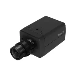
FIGURE 2-2: MOUNTING THE CAMERA
2.3.4 Connecting the Cables
The I/O interfaces will be seen on the rear panel of the box camera. Make the appropriate cable connections.
Power supply via one of the following 3 alternatives.
AC 24V: Connect a power cable that supplies AC24V power source to the terminal block, and then insert the terminal
block into the power port.
DC 12V: Connect a power cable that supplies DC12V power source to the terminal block, and then insert the terminal
block into the power port.
NOTE: The polarities should be matching when using DC12V power source.
PoE (Class 3): Connect an Ethernet cable terminated with RJ-45 connector to the PoE RJ-45 port for both power
supply and network connectivity purposes simultaneously.
NOTE:
If a Class I PoE adapter or switch is used to provide power, be sure that the power cord is firmly plugged into
the socket and confirm the main earth connection.
This product is intended to be supplied by a UL Listed Power Adapter or DC power source marked "L.P.S" (or
"Limited Power Source"), rated 24Vac, 1.1A or 12Vdc, 1.6A, Tma=50 degree C or 48Vdc, 350mA Gigabit
Passive PoE injector, 802.3af/at PSE.
Interconnecting cables for PoE is intended to be supplied by a UL Listed type CL3P, CL3R or CL3X, marked
“SUNLIGHT RESISTANT”, “SUN. RES.”, or "SR." and "water resistant" or “W”
(Optional) Insert audio/alarm/RS485 cables to the corresponding ports within rear panel of the box camera if required.
Mounting screw hole (1/4-20)
Safety wire (Sold separately)
Safety-cord screw
Loading ...
Loading ...
Loading ...