Loading ...
Loading ...
Loading ...

7
• Insert hex bolts through top holes in jack stand
mounting brackets and holes in jack stand. Secure
with lock washers and hex nuts. See Figure 3.
• Insert hex bolts through upper holes in the bottom
of mounting brackets and jack stand. Secure with
lock washers and hex nuts. See Figure 3.
Hitch Assembly
The hitch assembly is already attached to the tongue
before shipping. If not, follow instructions below:
• Remove the hardware from the hitch assembly and
place the hitch on the end of the tongue.
• Insert hex bolt through flat washer, end of safety
chain, spacer, and then rear hitch hole. Pivot the
end of safety chain so it faces the ball end of hitch.
See Figure 4.
Figure 4
• Insert other spacer, flat washer, and safety chain
on the other end of the hex bolt and secure with hex
lock nut. See Figure 4.
• Insert hex bolt through the front hole of hitch and
secure with flat washer and hex lock nut. Tighten
both hex nuts to 23 ft-lbs.
Attaching Wheels
• Block up the reservoir tank assembly about eight to
twelve inches.
• Remove and discard plastic shipping caps on the
outside of the wheels.
• Remove the cotter pin, hex slotted nut, and flat
washer from each axle.
NOTE: It is recommended that you polish the axles with
emery cloth before you install the wheels.
• Place a wheel on each axle with the valve stem
facing outward. See Figure 5.
• Place a flat washer on each axle and secure with
hex slotted nut.
• Tighten slotted nut until snug and then back off
approximately 1/3 turn or until one of the slots on
the slotted nut lines up with the hole in the axle.
• Insert cotter pins through slots in nuts and holes in
axle and secure by bending the ends of the cotter
pins in opposite directions. See Figure 5.
Figure 5
• The wheels should spin freely and there should be
no side to side play.
• Place hub caps in position on wheels and tap on to
the axle with a soft hammer or mallet.
IMPORTANT:
Maximum tire pressure under any
circumstance is 30 psi. Equal tire pressure should be
maintained at all times.
Attaching Fenders
• Remove the hex nuts, lock washers, flat washers,
and hex bolts from the side of tank.
• Determine the proper assembly holes in the
fenders over the tires against the tank.
• Insert hex bolts through flat washers, holes in
fenders, and tank. See Figure 5. Secure fender with
lock washers and hex nuts. Tighten securely.
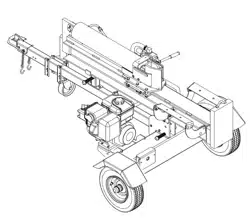
Attaching the Tongue
• Remove two hex bolts, lock washers, and hex nuts
on the front of the reservoir tank. See Figure 6.
• Place the tongue in position and secure with
hardware just removed.
• Remove the reservoir tank from the blocks.
Figure 6
T
ongu
e
Hex
Bolt
Flat
Washer
Spacer
Hex
Bolt
Hitch
Assembly
Chain
Nut
Lock
Wheel
Hub Cap
Cotter Pin
Hex Slotted
Nut
Flat
Washer
Fender
Lock
Washer
Hex
Nut
Hex
Bolt
Flat
Washer
Reservoir
Tank
Hex
Nuts
Lock
Washers
Hex
Bolts
Tongue
Reservoir
Tank
Loading ...
Loading ...
Loading ...