Loading ...
Loading ...
Loading ...
14
For the Installer
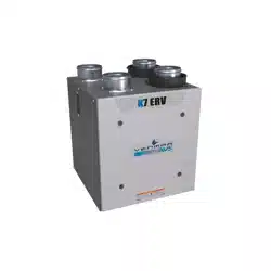
For a furnace connected to a cooling system:
On some older thermostats, energizing the “R” and “G” terminals at the furnace has the effect of energizing “Y” at the thermostat and
thereby turning on the cooling system. If you identify this type of thermostat, you must use the ALTERNATE FURNACE INTERLOCK WIRING.
STANDARD FURNACE INTERLOCK WIRING ALTERNATE FURNACE INTERLOCK WIRING
W R G
Y
W
R
G
C
Y
UNIT TERMINAL CONNECTOR
THERMOSTAT
TERMINALS
FOUR
WIRES
TWO WIRES
heating only
FURNACE
24-VOLT
TERMINAL BLOCK
TWO WIRES
COOLING SYSTEM
NO C NC I OC OL Y R G B
W R G Y
W
R
Y
R
G
Y
C
THERMOSTAT
TERMINAL
4 WIRES
2 WIRES
heating only
wiring
nuts
FURNACE
24-VOLT
TERMINAL BLOCK
2 WIRES
COOLING SYSTEM
NO
NC
C
UNIT TERMINAL CONNECTOR
NO C NC I OC OL Y R G B
VE0108A
7.3 ELECTRICAL CONNECTION TO THE FURNACE
⚠ WARNING
Never connect a 120-volt AC circuit to the terminals of the furnace interlock (standard wiring). Only use the low
voltage class 2 circuit of the furnace blower control.
8. BALANCING THE UNIT
PREPARATION
Follow these steps to ensure accurate measurements:
• Seal all the ductwork with tape. Close all windows and doors.
• Turn off all exhaust devices such as range hood, dryer and bathroom fans.
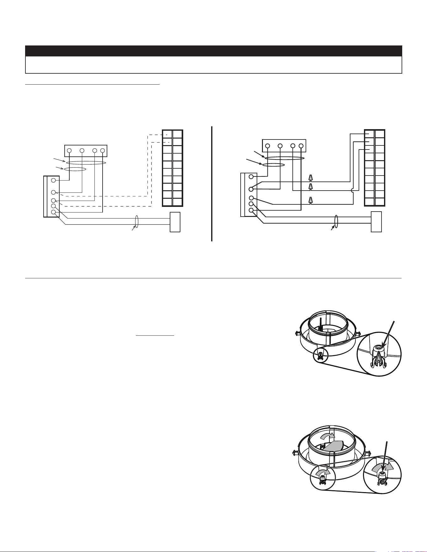
• Make sure the balancing dampers are fully open (their adjusment pin (A) must be vertical,
see illustration aside).
• Make sure all filters are clean (if it is not the first time the unit is balanced).
• If the installation is in any way connected to the ductwork of the cold air return of a furnace/air
handler, make sure that the furnace/air handler blower is ON. If not, leave furnace/air handler
blower OFF.
• If the outside temperature is below 0°C/32°F, make sure the unit is not running in defrost while
balancing by waiting 10 minutes after plugging the unit in.
• Set the unit to high speed.
BALANCING PROCEDURE
1. Place the magnehelic gauge on a level surface and adjust it to zero.
2. Connect tubing from gauge to EXHAUST air flow pressure taps (refer to label on unit for
gauge connection).
3. Be sure to connect the tubes to their appropriate high/low fittings. If the gauge drops below
zero, reverse the tubing connections.
4. Note the CFM value from balancing chart on unit.
5. Repeat steps 3 and 4, but to FRESH air flow pressure taps.
6. Using the appropriate adjustable balancing damper, lower the highest value so it matches
the lowest value. A difference up to ±10cfm is acceptable.
7. Secure both dampers in place with a fastening screw (included in the hardware kit).
8. Write the required air flow information on a label and stick it near the unit for future reference (date, maximum speed air flows, your
name, phone number and business address).
VJ0033
A
SCREW
VJ0031
Loading ...
Loading ...
Loading ...