

Safety information
Installation and removal of the AXIS
T8122 DC 30W Midspan must be
carried out by qualified personnel
only.
• DC Power Cable Set:
• The power cable must have regulatory
agency approval for the country in which
it is used (for example, UL, CSA, VDE).
• The power cable must be rated for a
minimum current capacity of 3 amps.
• The DC power source must be near the AXIS
Midspan and easily accessible. You can
remove DC power from the AXIS Midspan by
disconnecting the DC power cable from either
the power source or the AXIS Midspan.
• The AXIS Midspan data and data/power
interfaces are qualified as SELV (Safety Extra-
Low Voltage) circuits according to IEC 60950.
These interfaces can only be connected to
SELV interfaces on other equipment.
WARNING!
• Read the instructions before connecting
the Midspan to its power source.
• Follow basic safety measures while
connecting Midspan to power source.
• The GND pin on the 45-57V DC contact is
an isolated GND; do NOT connect it to
the GND-shield on the RJ45.
• Voltage mismatch can cause equipment
damage and may pose a fire hazard. If
voltage indicated on the label is different
from power source voltage, do not
connect Midspan to this power source.
• This product relies on the building
installation for short-circuit (over
current) protection. Ensure that the
power source is protected by a fuse or
circuit breaker.
• The Midspan "Data In" and "Data & Power
Out" ports are shielded RJ-45 data
sockets. They cannot be used as Plain Old
Telephone Service (POTS) telephone
sockets. Only RJ-45 data connectors may
be connected to these sockets.
Notice:
In keeping with its policy to improve products,
as new technology, components, software, and
firmware become available, Axis reserves the
right to change specifications without prior
notice.
Technical support (for Midspan and
Splitters)
Should you require technical assistance, please
contact your Axis reseller. If your questions
cannot be answered immediately, the reseller
will forward your queries through the
appropriate channels to ensure rapid response. If
you are connected to the Internet, you can:
• Download user documentation
• Find answers to resolved problems in the FAQ
database
• Search by product, category, or phrases
• Report problems to Axis support by logging in
to your private support area
• Visit Axis Support at www.axis.com/techsup/
Electromagnetic Compatibility (EMC)
This equipment generates, uses and can radiate
radio frequency energy and, if not installed and
used in accordance with the instructions, may
cause harmful interference to radio
communications. However, there is no
guarantee that interference will not occur in a
particular installation.
If this equipment does cause harmful
interference to radio or television reception,
which can be determined by turning the
equipment off and on, the user is encouraged to
try to correct the interference by one or more of
the following measures: Re-orient or relocate
the receiving antenna. Increase the separation
between the equipment and receiver. Connect
the equipment to an outlet on a different circuit
to the receiver. Consult your dealer or an
experienced radio/TV technician for help.
Shielded (STP) network cables must be used with
this unit to ensure compliance with EMC
standards.
USA - This equipment has been tested and
found to comply with the limits for a Class B
computing device pursuant to Subpart B of Part
15 of FCC rules, which are designed to provide
reasonable protection against such interference
when operated in a commercial environment.
Operation of this equipment in a residential area
is likely to cause interference, in which case the
user at his/her own expense will be required to
take whatever measures may be required to
correct the interference.
Canada - This Class B digital apparatus
complies with Canadian ICES-003.
Europe - This digital equipment fulfills
the requirements for radiated emission

according to limit B of EN55022, and the
requirements for immunity according to
EN55024 residential and commercial industry.
Japan - This is a class B product based on the
standard of the Voluntary Control Council for
Interference from Information Technology
Equipment (VCCI). If this is used near a radio or
television receiver in a domestic environment, it
may cause radio interference. Install and use the
equipment according to the instruction manual.
Australia - This electronic device meets the
requirements of the Radio communications
(Electromagnetic Compatibility) Standard AS/
NZS CISPR22.
WEEE Directive
The European Union has enacted a
Directive 2002/96/EC on Waste
Electrical and Electronic Equipment
(WEEE Directive). This directive is
applicable in the European Union
member states.
The WEEE marking on this product
(see right) or its documentation indicates that
the product must not be disposed off together
with household waste. To prevent possible harm
to human health and/or the environment, the
product must be disposed off in an approved and
environmentally safe recycling process. For
further information on how to dispose off this
product correctly, contact the product supplier,
or the local authority responsible for waste
disposal in your area.
Business users should contact the product
supplier for information on how to dispose off
this product correctly. This product should not
be mixed with other commercial waste. For more
information, visit www.axis.com/techsup/

AXIS T8122 DC 30W Midspan Page 5
ENGLISH
AXIS T8122 DC 30W Midspan
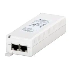
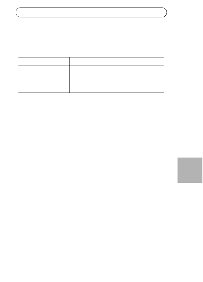
Package contents
Functions and features
The AXIS T8122 DC 30W Midspan injects 52V DC power into the spare
pairs of the Ethernet cabling. It complies with both IEEE802.3af and
IEEE802.3at standards. These power levels allow a new range of
Ethernet-based applications such as PTZ Cameras to use the Midspan.
Preliminary steps
• Ensure DC power is applied to the AXIS T8122, using an operational
DC cable with appropriate ground connection.
• Ensure that output Ethernet cable is connected to the Data & Power
Out port.
• Verify that a power-ready Ethernet compatible device or splitter is
connected.
Note:
Do not use a cross over cable between the AXIS T8122 output port
and the powered device.
AXIS Midspan AXIS T8122 DC 30W Midspan
Power connections Terminal blocks
Printed material Installation guide (this document)
Warranty document
Page 6 AXIS T8122 DC 30W Midspan
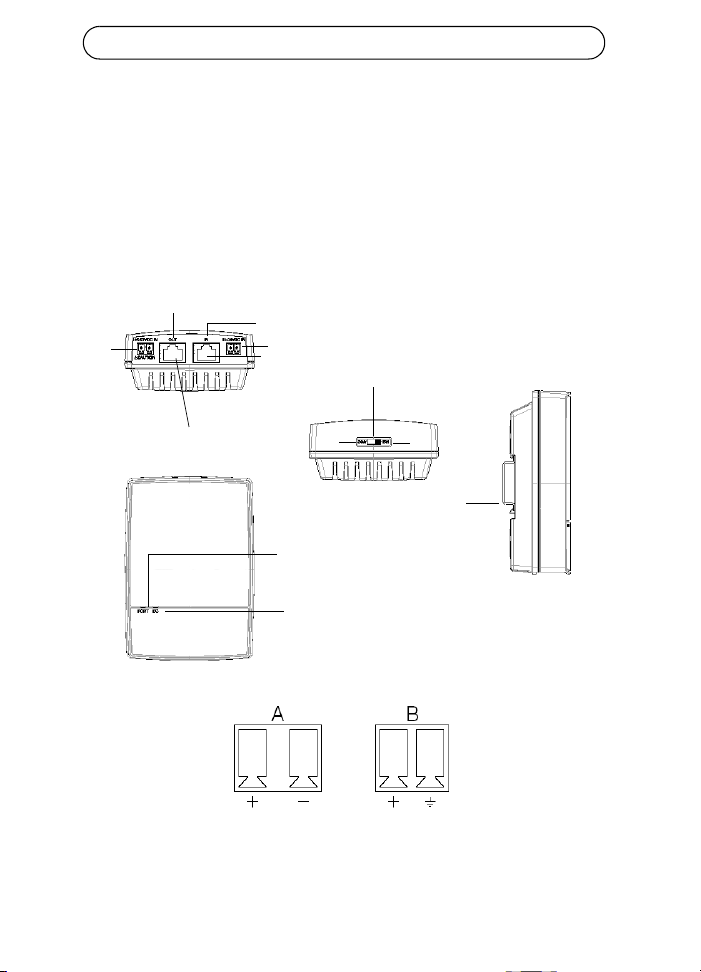
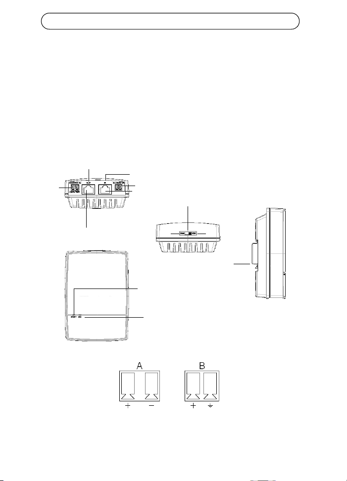
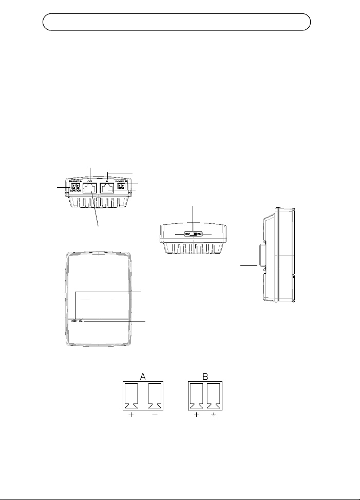
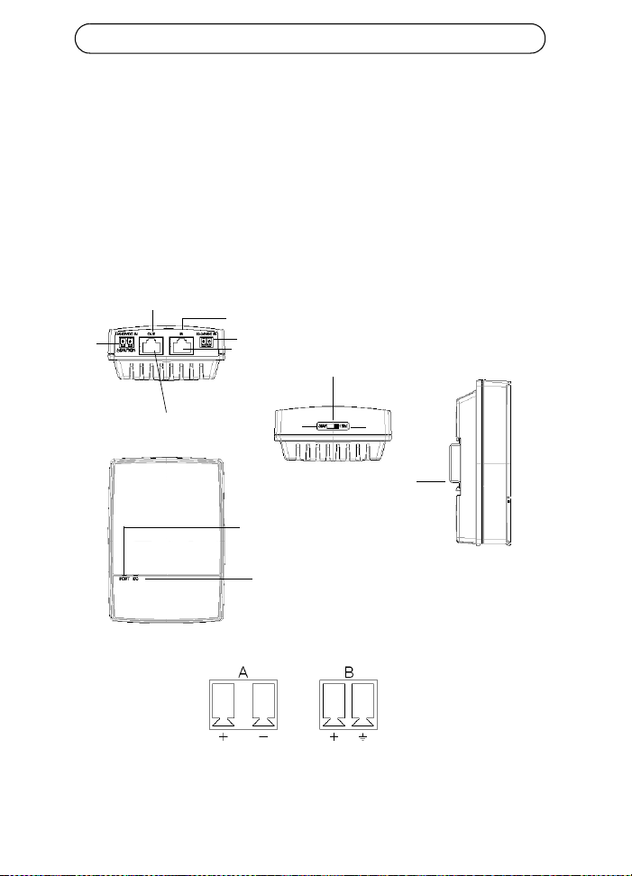
Installation
1. Connect the AXIS T8122 to a DC outlet (12-24V DC / 45-57V DC).
2. Connect the unit Data In jack (In) to your remote Ethernet network
switch using a shielded Ethernet cable.
3. Connect the Data & Power Out jack (Out) to your Axis splitter or
camera, using a shielded Ethernet cable.
Input
Input
Camera/splitters
Ethernet
Data and Power out
Data in
Port connectivity
indicator
DC Input connectivity
indicator
Power switch
DIN Rail
30W
15W
45-57V DC
12-24V DC
A
B
AXIS T8122 DC 30W Midspan Page 7
ENGLISH
Power switch - Before the unit is powered on, the power switch has to be
set in the correct position.
• Position 1 (30W): Use this setting if an 802.3at PoE camera is con-
nected to the midspan and the power source can deliver a minimum
of 40W.
• Use this setting if an 802.3af PoE camera is connected to the midspan
and the power source can deliver a minimum of 20W.
CAUTION!
The GND pin on the 45-57V DC contact is an isolated GND; do NOT
connect it to the GND-shield on the RJ45.
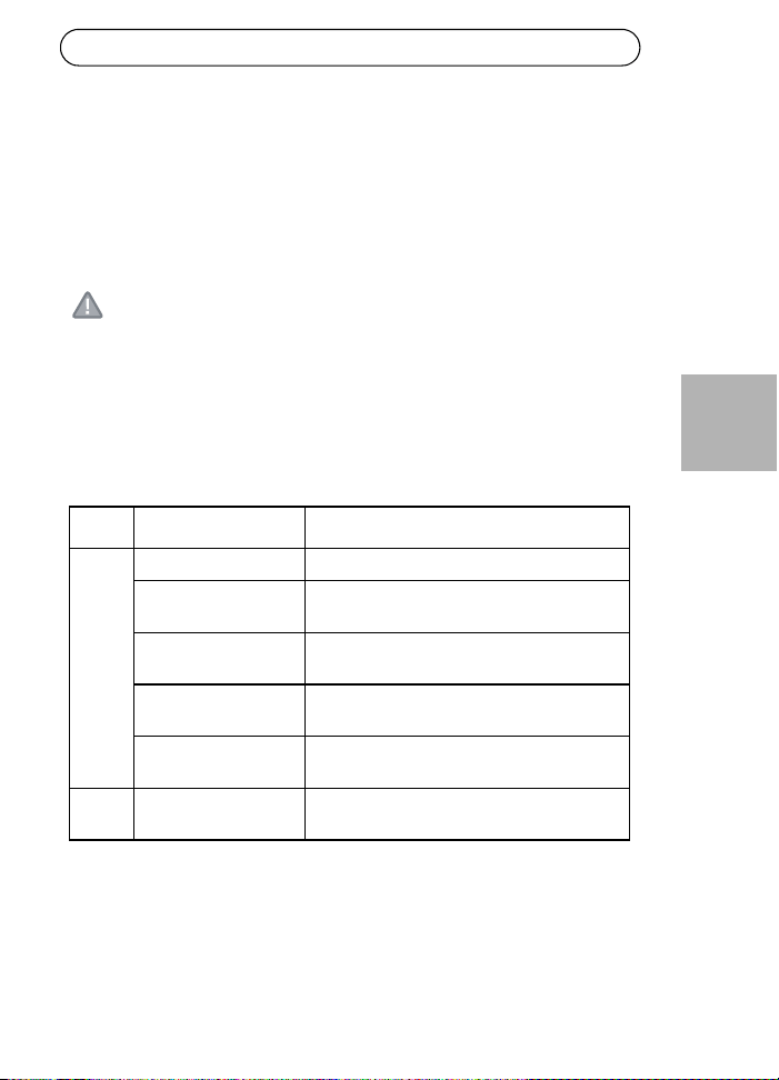
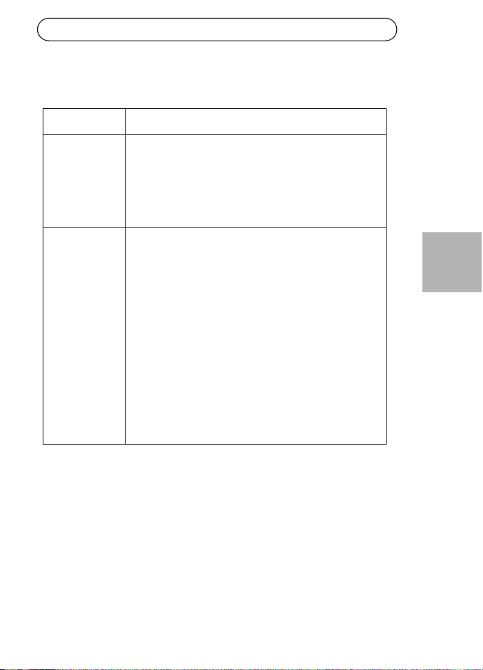
Indicators
LED Color Indication
Port Unlit No camera connected
Steady green Camera connected, normal behavior 802.3af
(15W)
Steady yellow Camera connected, normal behavior 802.3at
(30W)
Green/yellow 1 Hz
blinking
Over current or short circuit condition on the
port
Green/yellow 4 Hz
blinking
PSE input voltage out of range or other
internal fault
DC
input
Steady green DC power connected
Page 8 AXIS T8122 DC 30W Midspan
Mounting instructions
The AXIS T8122 may be wall or bench mounted using the rear side holes.
It can also be mounted on a DIN rail.
Note the following before mounting the AXIS T8122 to a fixed location:
• Do not cover the midspan or block the airflow to the product with any
foreign object. Keep the midspan away from excessive heat and
humidity, and free from vibration and dust.
• Ensure that the cable length from the Ethernet network source to
your Axis video product does not exceed 100 meters (333 feet). See
page 10 for information on cable lengths. The midspan is not a
repeater and does not amplify the Ethernet data signal.
• Use a splitter if required, but ensure that the splitter is connected
close to your Axis video product and not to the Midspan.
• There is no "on-off" switch; simply plug the AXIS T8122 into a DC
power outlet.
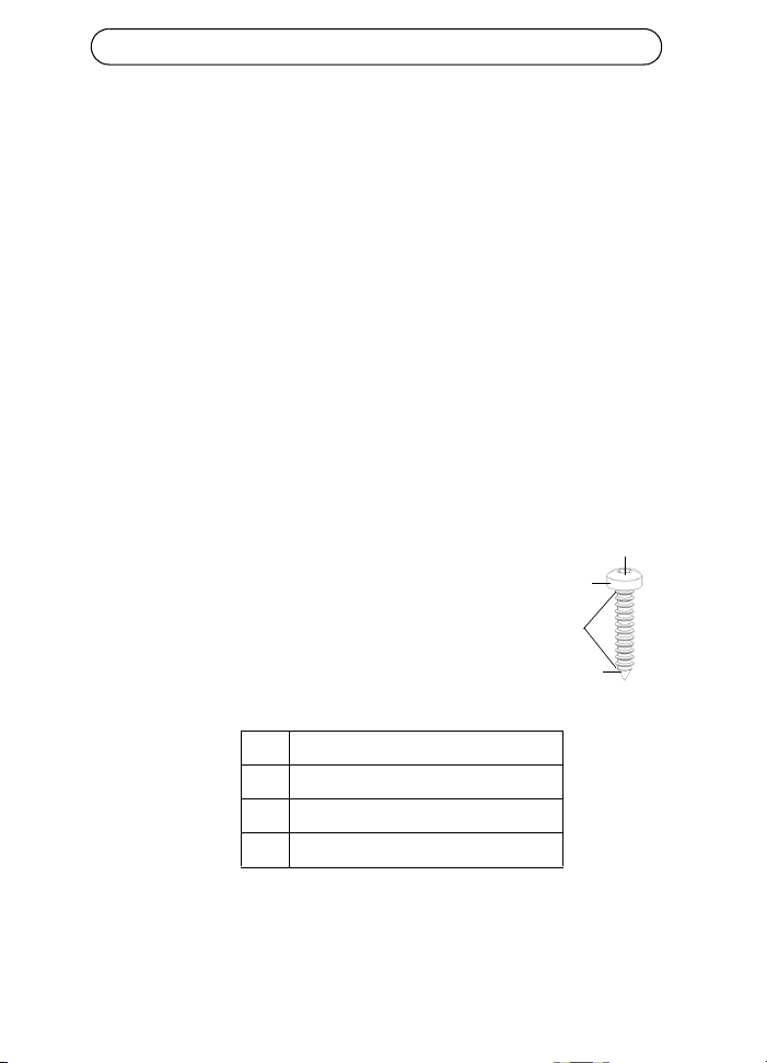
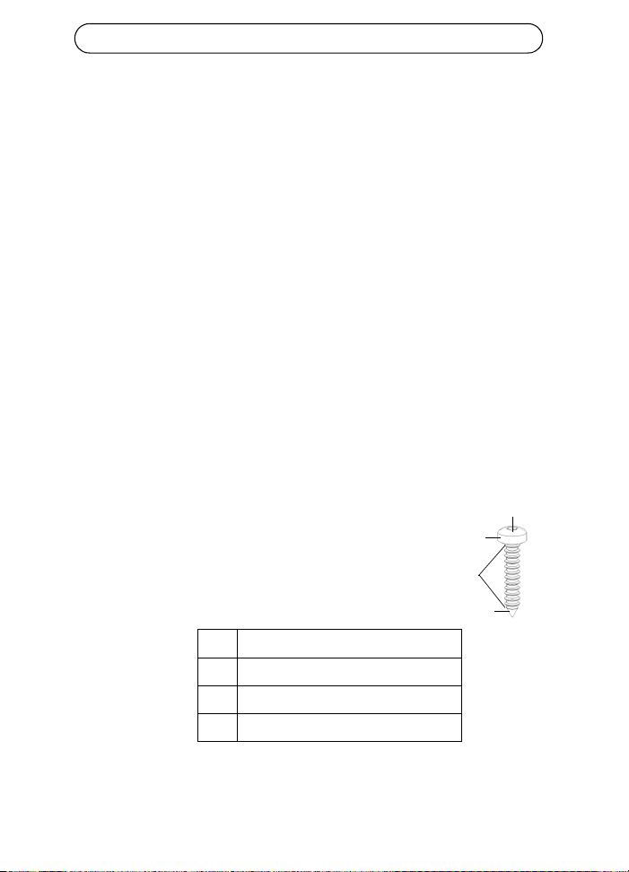
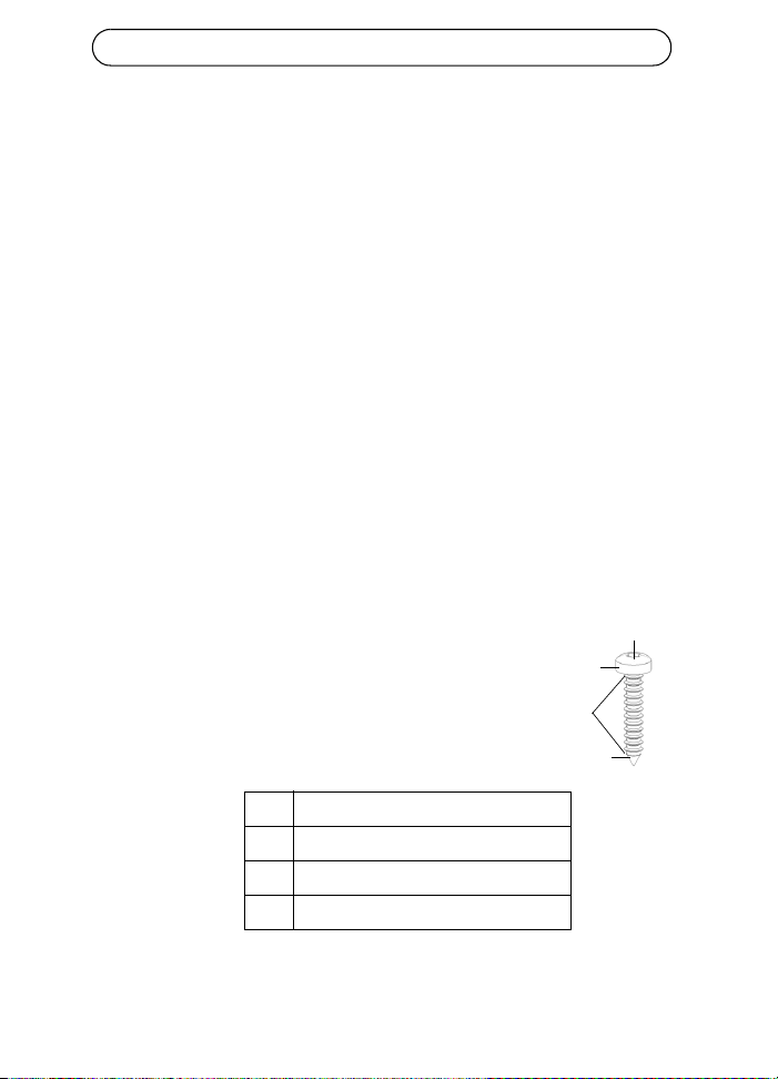
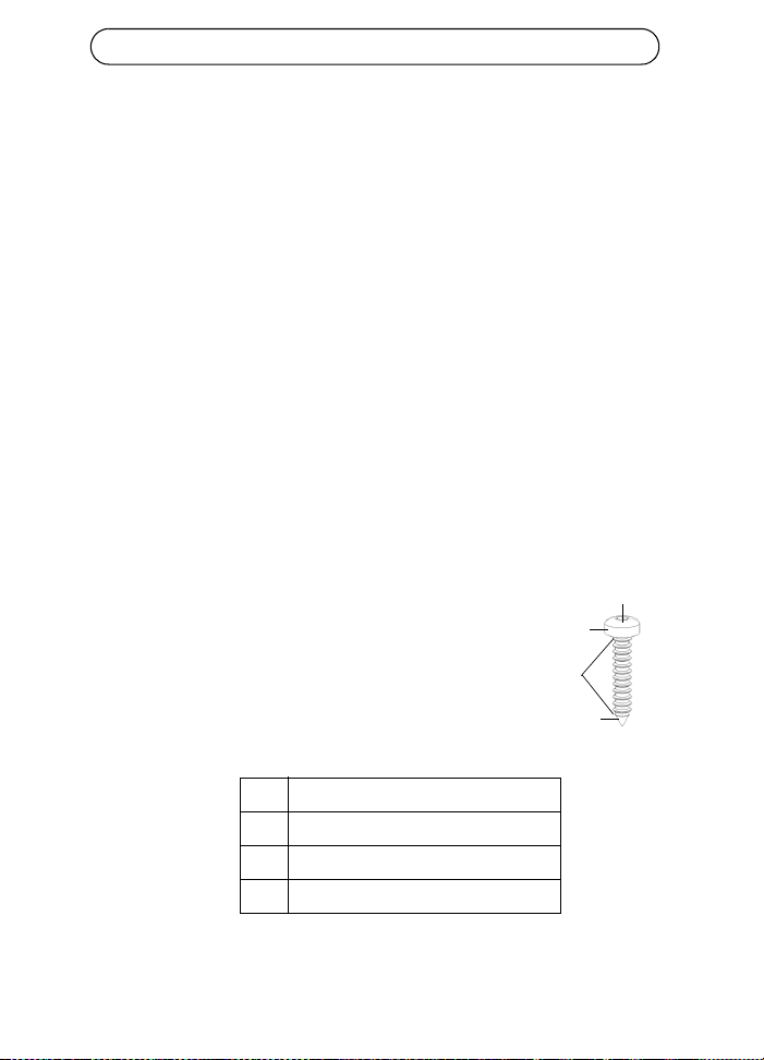
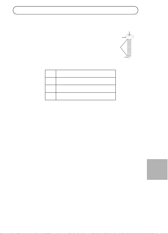
To mount:
1. Install two screws vertically at a distance of 65 mm
(2.5”) on the wall or shelf.
2. Align the AXIS T8122 mounting slots to capture the
surface screws
A 6 to 7 mm (0.23" to 0.27")
B max 2.5 mm
C 2 mm to 3 mm (0.059" to 0.098")
D 3.0 mm (0.12")
A
B
D
c
AXIS T8122 DC 30W Midspan Page 9
ENGLISH
Specifications
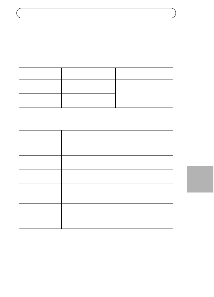
Environmental
Electrical
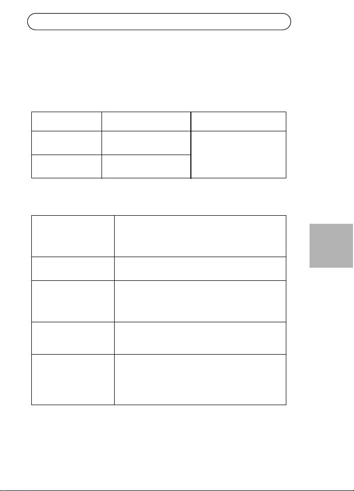
Mode Temperature Humidity
Operating -20 to 65°C
-4 to 149°F
max 95% (non-condensing)
Storage -40 to 74°C
-24 to 158°F
DC Input voltage 1
DC Input voltage 2
12 to 24 V DC (max. 40 W)
45 to 57 V DC (max. 35 W)
Input current Max. 3A @ 12-24V DC
Max. 0.7A @ 45-57V DC
Maximum Available
Output Power
52V DC @ 12-24V DC in (max. 30W)
57V DC @ 45-57V DC in (max. 30W)
Nominal Output
Voltage
51V DC @ 12-24V DC
0.5V lower then input voltage @ 45-57V DC
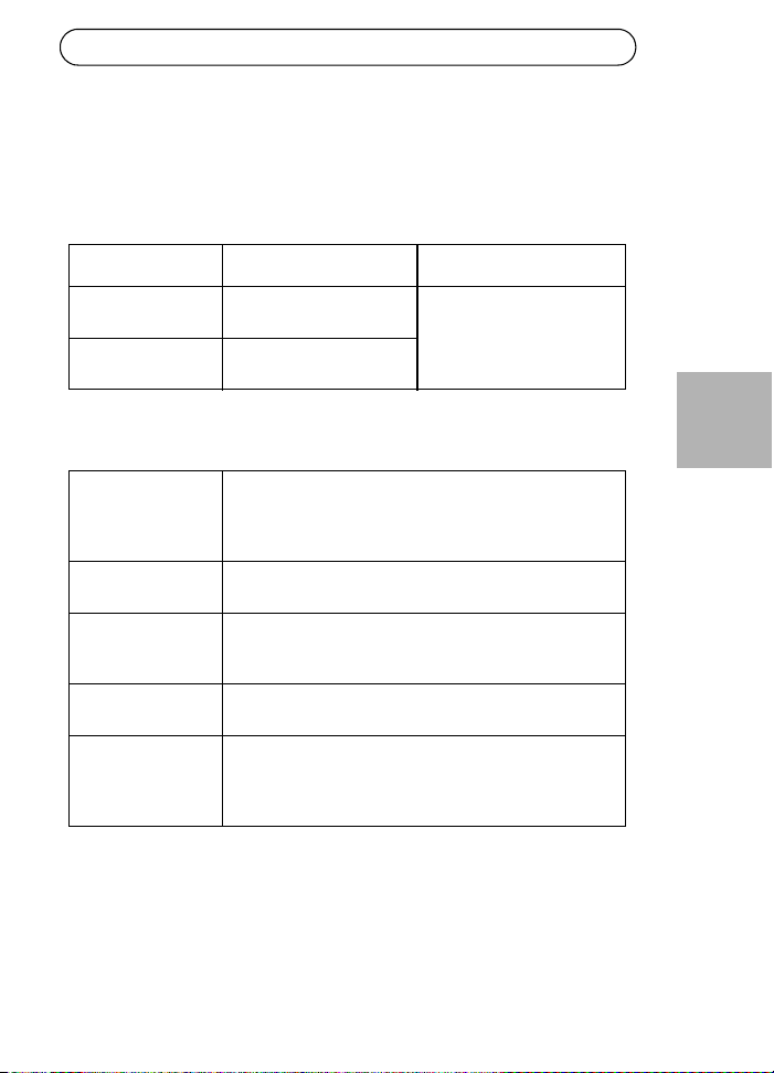
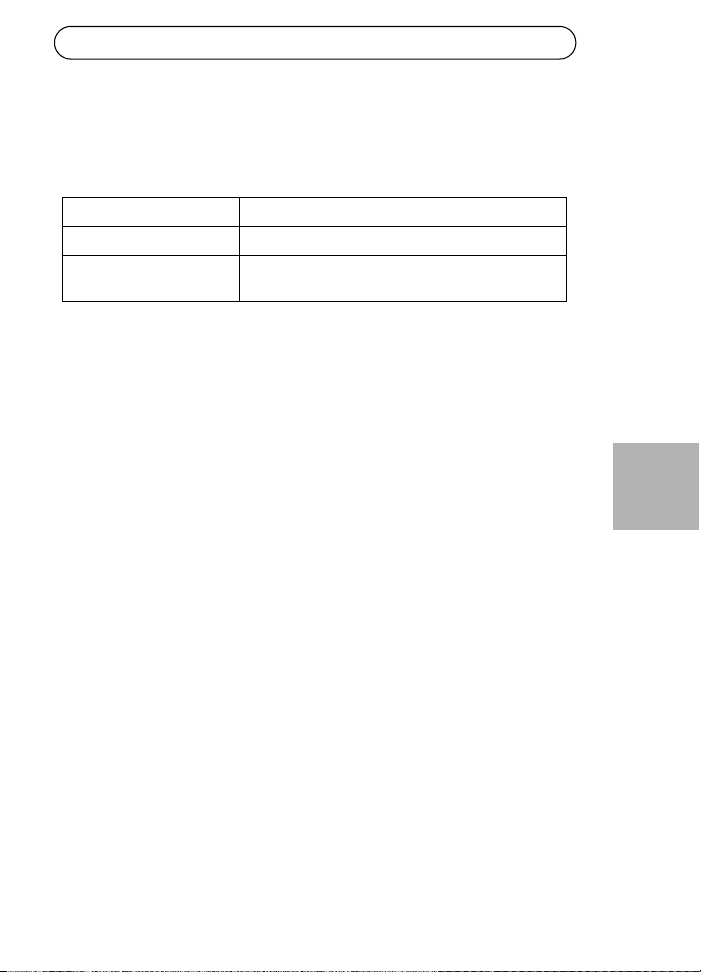
Compliable Ethernet
cable lengths
When an 802.3af device is powered, all cables up to 100m
are compliable.
See table below when an 802.3at device is powered.
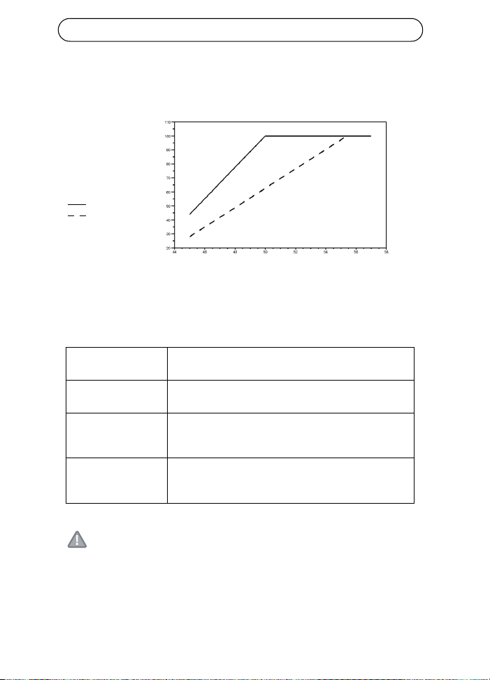
Page 10 AXIS T8122 DC 30W Midspan
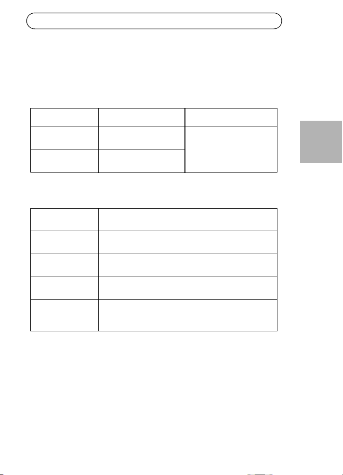
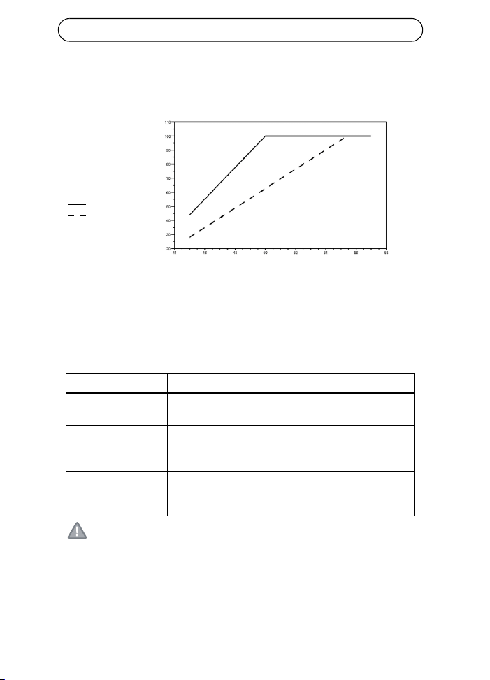
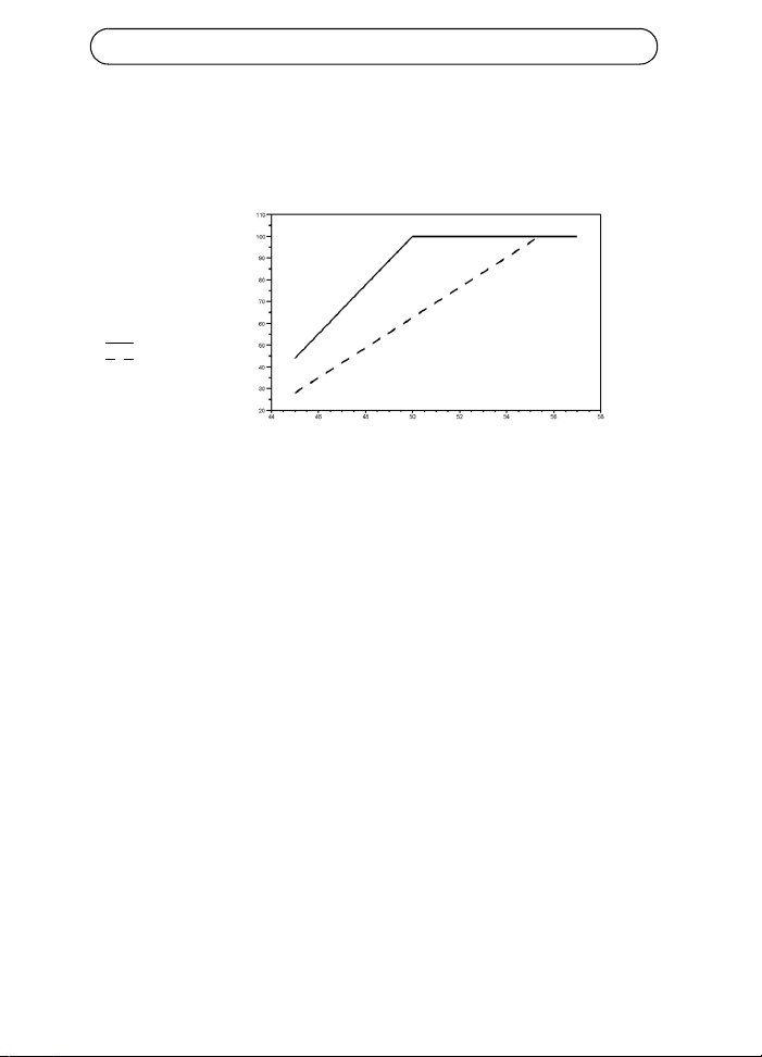
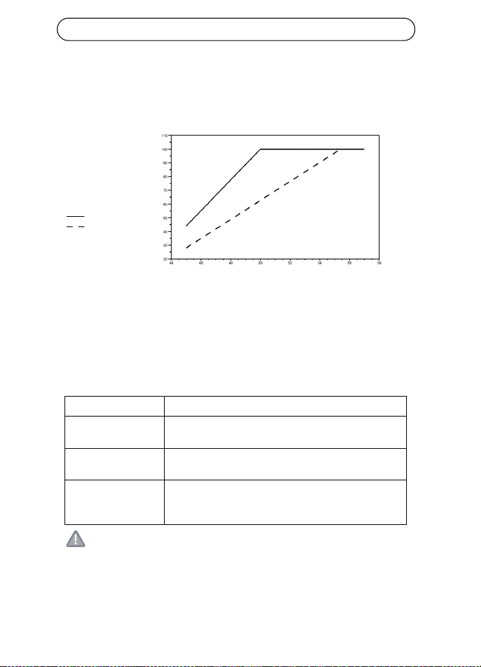
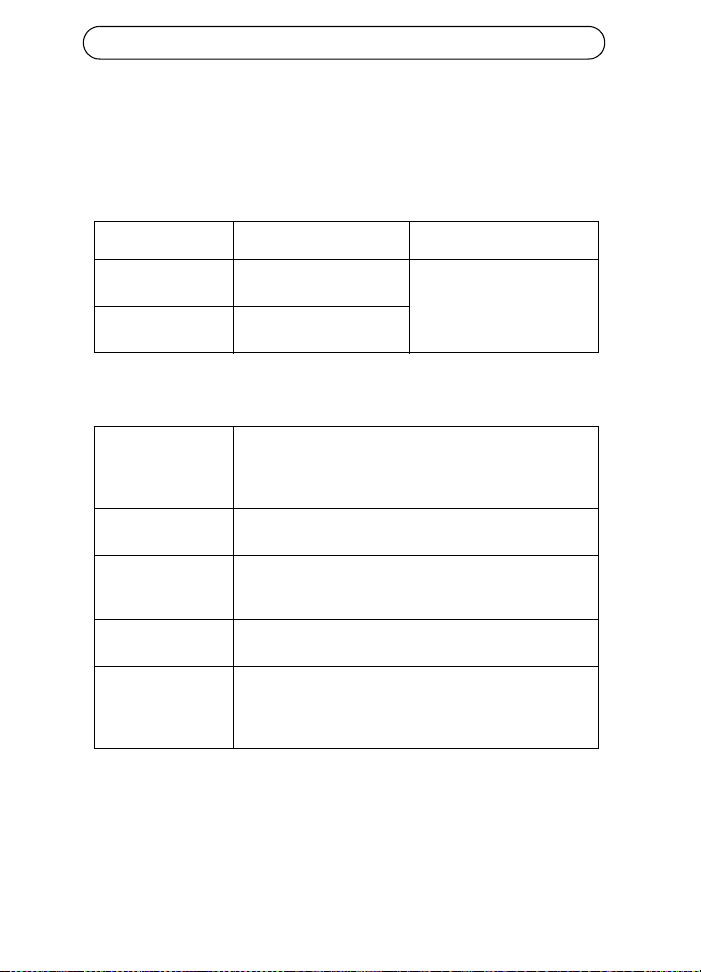
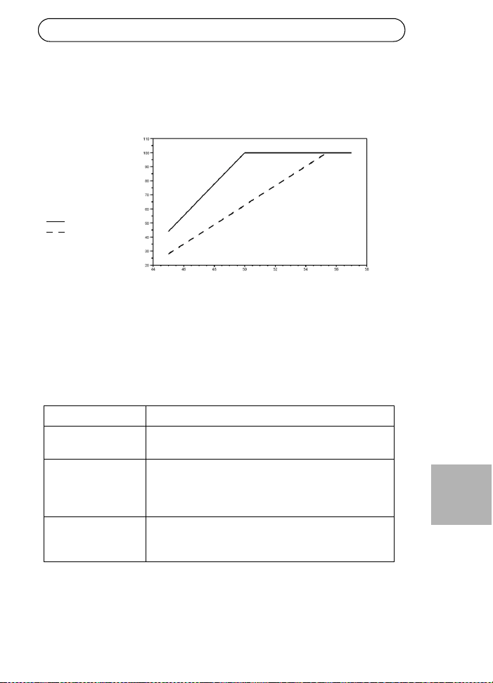
Maximum cable length between network switch and powered device
When the unit is powered through the 12-24V DC input, the maximum
length of network cable is: 70 m @ Cat5 and 100 m @ Cat5e/6.
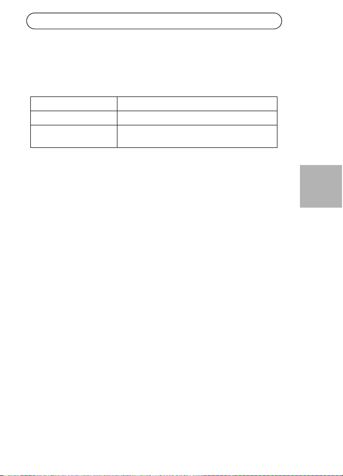
Ethernet interface
CAUTION!
The GND pin on the 45-57V DC contact is an isolated GND; do NOT
connect it to the GND-shield on the RJ45.
Input (Data In): Shielded RJ-45 EIA 568A and 568B
Output (Data &
Power Out):
Shielded RJ-45 EIA 568A and 568B
Wiring Data provided over pairs 1/2 and 3/6 for 10/100
Ethernet
Power over spare pairs 4/5 (+) and 7/8 (-)
Network cable Shielded category 5 (or higher)
Using a Cat 5e/6 is recommended while powering an
802.3at device.
Input voltage
Max cable
length between
network switch
and powered
device in meters
Cat5e/6
Cat5
AXIS T8122 DC 30W Midspan Page 11
ENGLISH
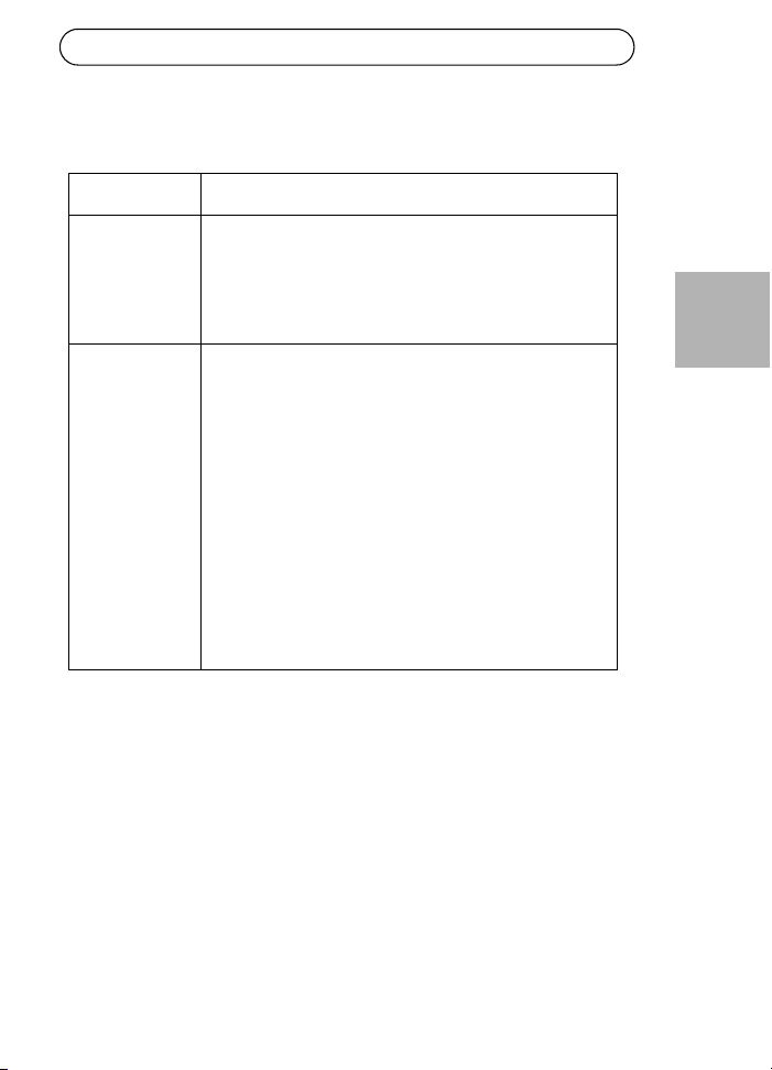
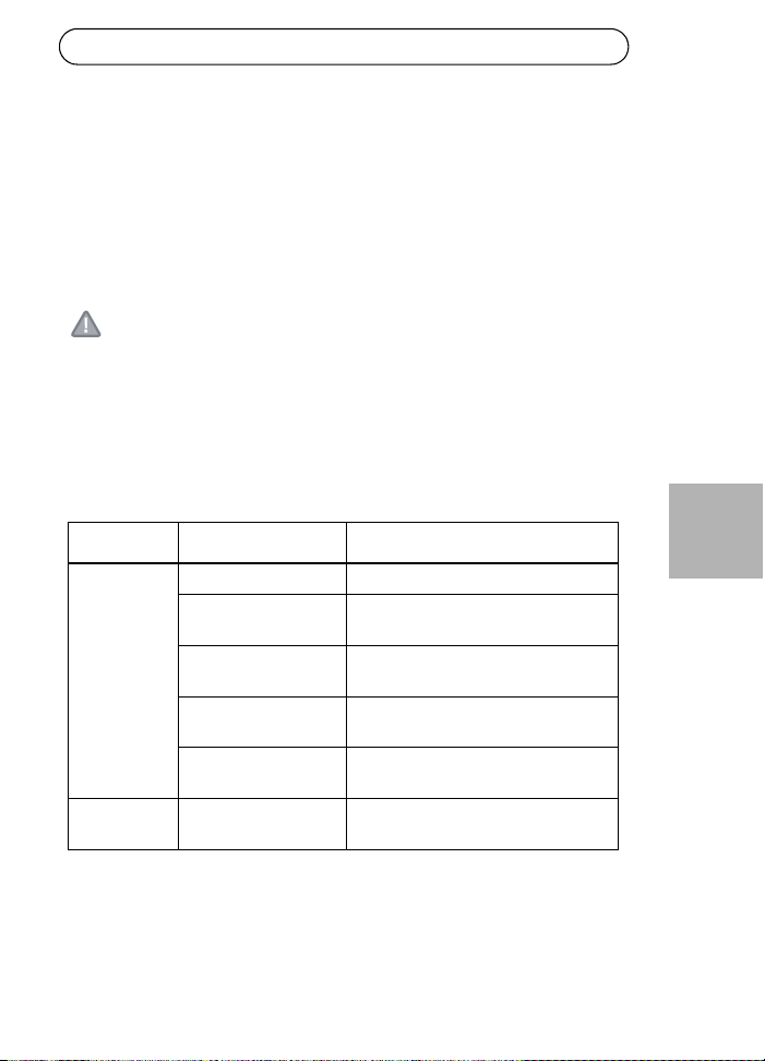
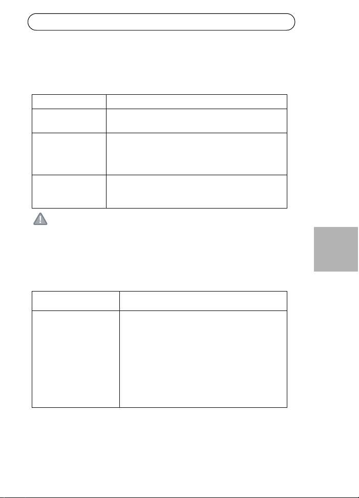
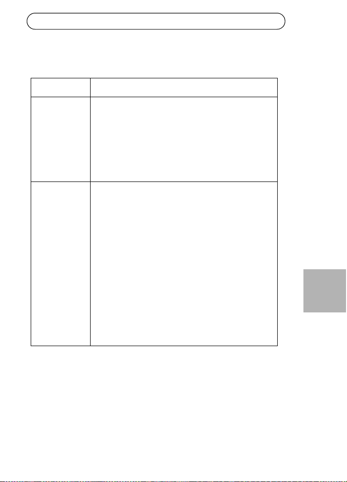
Troubleshooting
Symptom Corrective steps
Midspan does
not power up
1. Verify that an approved power cable is used.
2. Verify that the voltage at the power inlet is between
12-24V DC for Input voltage 1 and between 45-57V DC
for Input voltage 2.
3. Remove and re-apply power to the device and check
the indicators during power up sequence.
A port indicator
is not lit and the
PD (powered
device) does not
operate
1. The Midspan did not detect a PD; and the port is not
enabled.
2. Verify that the PD is designed for PoE operation.
3. Verify that you are using a standard Category 5/5e/6,
straight-wired cable, with four pairs.
4. If there is an external PoE device connected, replace it
to verify that it is functioning properly.
5. Ensure that the input Ethernet cable is connected to
the Data In port.
6. Verify that the PD is connected to the Data & Power
port.
7. Try to reconnect the same PD into a different Midspan.
If it works, there is probably a faulty port or RJ-45
connection.
8. Verify that there is no shortcut over any of the twisted
pair cables or over the RJ45 connectors.
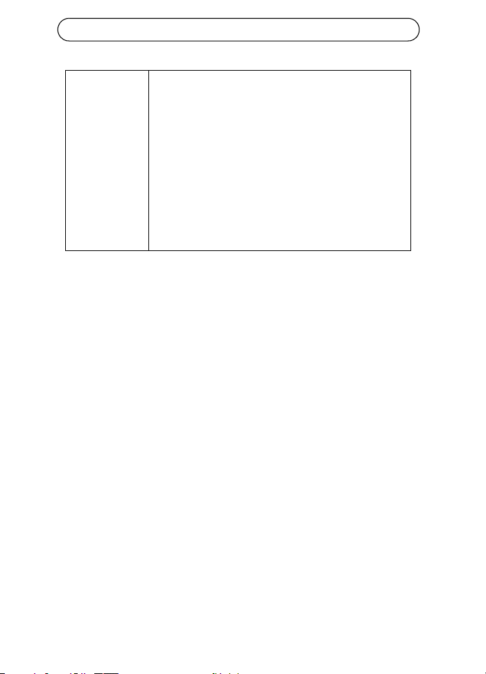
Page 12 AXIS T8122 DC 30W Midspan
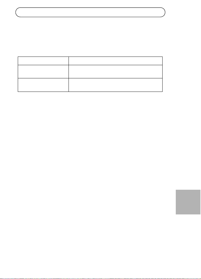
The end device
operates, but
there is no
data link
1. Verify that the port indicator on the front panel is
continuously lit.
2. If an external PoE device is in use, replace it with a
good PoE device.
3. Verify that for this link, you are using standard UTP/FTP
Category 5 straight (non-crossover) cabling, with all
four pairs.
4. Verify that the Ethernet cable length is less than 100
meters (333 feet) from the Ethernet source to the
powered device. See Maximum cable length between
network switch and powered device, on page 10.
5. Try to reconnect the same PD into a different Midspan.
If it works, there is probably a faulty port or RJ-45
connection.
Injecteur AXIS T8122 DC 30W Page 13
FRANÇAIS
Injecteur AXIS T8122 DC 30W
Contenu de l'emballage
Fonctions et caractéristiques
Votre Injecteur AXIS T8122 DC 30W envoie une puissance de 52 V CC
dans les paires inutilisées du câblage Ethernet. Il est conforme aux
normes IEEE802.3af et IEEE802.3at. Ces niveaux de puissance offrent
une nouvelle gamme d'applications en réseau telles que les caméras PTZ
en utilisant l'injecteur.
Étapes préliminaires
• Vérifiez que votre AXIS T8122 est raccordé à un câble CC en bon état
de fonctionnement et correctement mis à la terre.
• Vérifiez que le câble Ethernet de sortie est branché sur le port de
données et d'alimentation de sortie.
• Vérifiez qu'un périphérique ou qu'un séparateur compatible Ethernet
prêt à être branché est connecté.
Remarque :
N'utilisez pas de câble simulateur de modem entre le port de sortie
de votre AXIS T8122 et le périphérique sous tension.
Injecteur AXIS Injecteur AXIS T8122 DC 30W
Connexions d'alimentation Blocs terminaux
Documentation Guide d'installation (le présent document)
Garantie

Page 14 Injecteur AXIS T8122 DC 30W
Installation
1. Branchez votre AXIS T8122 sur une prise CC (12-24 V CC/45-
57 V CC).
2. Branchez le connecteur de données d'entrée (entrée) au
commutateur réseau Ethernet distant à l'aide d'un câble Ethernet
blindé.
3. Branchez le connecteur de données et d'alimentation de sortie
(sortie) sur votre séparateur ou caméra Axis à l'aide d'un câble
Ethernet blindé.
Entrée
Entrée
Caméra/séparateurs
Ethernet
Données et alimentation de sortie
Données d'entrée
Indicateur de connexion du port
indicateur
Connectivité d'entrée CC
indicateur
Interrupteur
Rail DIN
30 W
15 W
45-57 V CC
12-24 V CC
B
A
Injecteur AXIS T8122 DC 30W Page 15
FRANÇAIS
Interrupteur - Avant d'allumer l'unité, vous devez mettre le bouton
d'alimentation sur la bonne position.
• Position 1 (30 W) : utilisez ce réglage si une caméra 802.3at PoE est
reliée à l'injecteur et si la source d'alimentation peut fournir au moins
40 W.
• Utilisez ce réglage si une caméra 802.3af PoE est reliée à l'injecteur et
si la source d'alimentation peut fournir au moins 20 W.
ATTENTION !
La broche GND sur le contact 45-57 V CC est une broche GND isolée.
Vous ne devez PAS la relier au blindage GND du RJ45.
Indicateurs
DEL Couleur Indication
Port Éteint Aucune caméra connectée
Vert continu Caméra 802.3af connectée, fonctionnement
normal (15 W)
Jaune continu Caméra 802.3at connectée, fonctionnement
normal (30 W)
Vert/jaune 1 Hz
clignotant
Surintensité ou court-circuit sur le port
Vert/jaune 4 Hz
clignotant
Tension d'entrée PSE hors limites ou autre
défaillance interne
Entrée
CC
Vert continu Alimentation CC connectée
Page 16 Injecteur AXIS T8122 DC 30W
Instructions de montage
Votre AXIS T8122 peut être fixé au mur ou monté sur banc à l'aide des
trous situés au dos de l'appareil. Il peut également être monté sur un rail
DIN.
Prennez note de ce qui suit avant de poser votre AXIS T8122 à un endroit
fixe :
• Ne recouvrez pas l'injecteur ou ne bloquez pas son système d'aération
par des corps étrangers. Conservez l'injecteur à l'abri des excès de la
chaleur et de l'humidité, des vibrations et de la poussière.
• Veillez à ce que la longueur de câble entre la source du réseau
Ethernet et votre produit vidéo Axis ne dépasse pas 100 mètres (333
pieds). Reportez-vous à la page 18 pour plus d'informations sur les
longueurs de câble. L'injecteur n'est pas un répéteur et il n'amplifie
pas le signal des données Ethernet.
• Utilisez un diviseur si vous le souhaitez, en veillant à ce qu'il soit
branché à proximité de votre produit vidéo Axis et non sur l'injecteur.
• Il n'y a pas de bouton "marche/arrêt". Il vous suffit de brancher votre
AXIS T8122 à une prise de courant CC.
Pour monter :
1. Placez deux vis à la verticale à une distance de 65 mm
(2,5") sur le mur ou l'étagère.
2. Alignez les fentes de montage de votre AXIS T8122
pour incruster les vis de surface
A 6 à 7 mm (0,23" à 0,27")
Bmax. 2,5mm
C 2 mm à 3 mm (0,059" à 0,098")
D 3,0 mm (0,12")
A
B
D
c
Injecteur AXIS T8122 DC 30W Page 17
FRANÇAIS
Caractéristiques techniques
Conditions d'utilisation
Électrique
Mode Température Humidité
En fonctionnement -20 à 65 °C
-4 à 149 °F
95 % max. sans
condensation
Stockage -40 à 74 °C
-24 à 158 °F
Tension
d'entrée CC 1
Tension
d'entrée CC 2
12 à 24 V CC (max. 40 W)
45 à 57 V CC (max. 35 W)
Courant d'entrée Max. 3 A à 12-24 V CC
Max. 0,7 A à 45-57 V CC
Puissance de sortie
disponible
maximum
52 V CC à 12-24 V CC en entrée (max. 30 W)
57 V CC à 45-57 V CC en entrée (max. 30 W)
Tension de sortie
nominale
51 V CC à 12-24 V CC
0,5 V de moins que la tension d'entrée à 45-57 V CC
Longueurs de câble
Ethernet conformes
Lorsqu'un dispositif 802.3af est sous tension, tous les
câbles de 100 mètres maximum sont conformes.
Reportez-vous au tableau ci-dessous dans le cas où un
dispositif 802.3at est sous tension.
Page 18 Injecteur AXIS T8122 DC 30W
Longueur de câble maximum entre le commutateur réseau et le
dispositif sous tension
Lorsque l'unité est alimentée par une entrée 12-24 V CC, la longueur
maximum du câble réseau est : 70 m à Cat5 et 100 m à Cat5e/6.
Interface Ethernet
ATTENTION !
La broche GND sur le contact 45-57 V CC est une broche GND isolée.
Vous ne devez PAS la relier au blindage GND du RJ45.
Entrée (données
d'entrée) :
RJ-45 EIA 568A et 568B blindé
Sortie (données et
puissance de sortie) :
RJ-45 EIA 568A et 568B blindé
Câblage Données fournies sur les paires 1/2 et 3/6 pour 10/100
Ethernet
Alimentation sur les paires inutilisées 4/5 (+) et 7/8 (-)
Câble réseau Catégorie 5 (ou supérieure) blindée
Il est recommandé d'utiliser une Cat5e/6 pour alimenter
un dispositif 802.3at.
Tension d'entrée
Longueur de câble
maximum entre
le commutateur réseau
et le dispositif
sous tension en mètres
Cat5e/6
Cat5
Injecteur AXIS T8122 DC 30W Page 19
FRANÇAIS
Dépannage
Symptôme Correction
L'injecteur ne se
met pas sous
tension.
1. Vérifiez qu'un câble d'alimentation approuvé est
utilisé.
2. Vérifiez que la tension à l'arrivée se situe entre
12 et 24 V CC pour la tension d'entrée 1 et entre
45 et 57 V CC pour la tension d'entrée 2.
3. Mettez l'injecteur hors tension et rallumez-le en
vérifiant les indicateurs pendant la mise sous tension.
Un indicateur de
port est éteint et
le périphérique
sous tension ne
fonctionne pas.
1. L'injecteur n'a pas détecté de périphérique sous
tension. Le port est donc désactivé.
2. Vérifiez que le périphérique sous tension prend en
charge la technologie PoE.
3. Vérifiez que vous utilisez un câble à fils droits ordinaire
de catégorie 5/5e/6 à quatre paires.
4. Si un dispositif PoE externe est utilisé, remplacez-le
pour vous assurer qu'il fonctionne correctement.
5. Vérifiez que le câble Ethernet d'entrée est branché sur
le port de données d'entrée.
6. Vérifiez que le périphérique sous tension est branché
sur le port de données et d'alimentation.
7. Essayez de rebrancher le périphérique sous tension sur
un injecteur différent. Si cela fonctionne, il est probable
que le connecteur RJ-45 soit défectueux.
8. Vérifiez qu'il n'y a pas de court-circuit sur les câbles à
paires torsadées ni sur les connecteurs RJ45.

Page 20 Injecteur AXIS T8122 DC 30W
Le périphérique
final
fonctionne,
mais il n'y a
pas de liaison
de données.
1. Vérifiez que l'indicateur de port à l'avant de l'appareil
est allumé en continu.
2. Si un dispositif PoE externe est utilisé, remplacez-le par
un dispositif PoE que vous savez en bon état de
fonctionnement.
3. Vérifiez que, pour cette liaison, vous utilisez un câble
droit UTP/FTP ordinaire de catégorie 5 (et non un câble
simulateur de modem), avec les quatre paires.
4. Vérifiez que le câble Ethernet ne fait pas plus de
100 mètres (333 pieds) de long entre la source Ethernet
et le périphérique sous tension. Reportez-vous à
Longueur de câble maximum entre le commutateur
réseau et le dispositif sous tension, page 18.
5. Essayez de rebrancher le périphérique sous tension sur
un injecteur différent. Si cela fonctionne, il est probable
que le connecteur RJ-45 soit défectueux.
AXIS T8122 DC 30W Midspan Seite 21
DEUTSCH
AXIS T8122 DC 30W Midspan
Inhalt des Produktpakets
Funktionen und Merkmale
Der AXIS T8122 DC 30W Midspan liefert 52-V-Gleichstrom über die
ungenutzten Leitungspaare des Ethernet-Kabels. Er erfüllt die Standards
IEEE802.3af und IEEE802.3at. Mithilfe dieser Stromstärken kann der
Midspan in zahlreichen neuen Ethernet-basierten Anwendungen, z. B.
PTZ-Kameras eingesetzt werden.
Vorbereitende Schritte
• Stellen Sie sicher, dass der AXIS Midspan über ein einsatzbereites
Netzkabel mit einer entsprechenden Erdung mit Gleichstrom versorgt
wird.
• Stellen Sie sicher, dass das ausgehende Ethernet-Kabel am Daten-
und Stromausgang angeschlossen ist.
• Prüfen Sie, ob ein netzstromfähiges, Ethernet-kompatibles Gerät bzw.
ein Splitter angeschlossen sind.
Hinweis:
Verwenden Sie kein gekreuztes Ethernet-Kabel (crossovercable)
zwischen dem Ausgang des AXIS T8122 und dem Gerät, das mit
Strom versorgt wird.
AXIS Midspan AXIS T8122 DC 30W Midspan
Netzanschlüsse Anschlussblöcke
Gedruckte Dokumente Installationsanleitung (dieses Dokument)
Garantieerklärung
Seite 22 AXIS T8122 DC 30W Midspan
Installation
1. Schließen Sie den AXIS T8122 an eine Netzsteckdose (12-24 V
Gleichstrom / 45-57 V Gleichstrom) an.
2. Verbinden Sie den Dateneingang (Buchse „Data In“) des Geräts über
ein abgeschirmtes Ethernet-Kabel mit dem Netzwerk-Switch des
Remote-Ethernet-Netzwerks.
3. Verbinden Sie den Daten- und Stromausgang (Buchse „Data &
Power Out“) über ein abgeschirmtes Ethernet-Kabel mit dem Axis
Splitter bzw. der Kamera.
Eingang
Eingang 12-24 V Gleichstrom
Kamera/Splitter
Ethernet
Daten- und Stromausgang
Dateneingang
Anschluss-
anzeige
Netzeingangs-
anzeige (Gleichstrom)
Netzschalter
Tragschiene
30 W
15 W
45-57 V Gleichstrom
B
A
AXIS T8122 DC 30W Midspan Seite 23
DEUTSCH
Netzschalter - Bevor Sie das Gerät einschalten, schieben Sie zunächst den
Netzschalter in die richtige Position.
• Position 1 (30 W): Verwenden Sie diese Einstellung, wenn Sie PoE-
Kameras gemäß 802.3at an den Midspan anschließen und die
Stromquelle mindestens 40 W liefert.
• Verwenden Sie diese Einstellung, wenn Sie PoE-Kameras gemäß
802.3af PoE an den Midspan anschließen und die Stromquelle
mindestens 20 W liefert.
VORSICHT!
Der Kontakt Masse am Kontakt 45-57V Gleichstrom ist isoliert.
Verbinden Sie ihn daher NICHT mit der Abschirmung der Masse am RJ45.
Anzeigen
LED Farbe Bedeutung
Anschluss Leuchtet nicht Keine Kamera angeschlossen
Konstant grün Kamera verbunden, normales
Verhalten 802.3af (15 W)
Konstant gelb Kamera verbunden, normales
Verhalten 802.3at (30 W)
Grün/gelb 1 Hz (blinkt) Überlast oder Kurzschluss am
Anschluss
Grün/gelb 4 Hz (blinkt) PSE-Eingangsspannung außerhalb des
Bereichs oder anderer interner Fehler
Netzeingang
(Gleichstrom)
Konstant grün Gleichstrom verbunden
Seite 24 AXIS T8122 DC 30W Midspan
Montageanweisungen
Der AXIS T8122 kann mithilfe der rückseitigen Löcher entweder an der
Wand oder auf einem Tisch angebracht werden. Die Anbringung auf
einer Tragschiene ist ebenso möglich. Beachten Sie vor der Montage des
AXIS T8122 auf einer festen Oberfläche bitte Folgendes:
• Decken Sie den Midspan nicht ab bzw. versperren Sie den Luftstrom
zum Midspan nicht mit Fremdkörpern. Halten Sie den Midspan von
übermäßiger Wärme und Feuchtigkeit fern und setzen Sie ihn weder
Vibrationen noch Staub aus.
• Stellen Sie sicher, dass die Kabellänge von der Ethernet-
Netzwerkquelle zum Axis Videoprodukt 100 Meter nicht überschreitet.
Weitere Informationen zu den Kabellängen finden Sie auf Seite 26.
Der Midspan ist kein Repeater und verstärkt damit nicht das
Datensignal der Ethernet-Verbindung.
• Verwenden Sie, falls nötig, einen Splitter; vergewissern Sie sich
jedoch, dass der Splitter in der Nähe des Axis Videoprodukts und nicht
am Midspan sitzt.
• Es ist kein Netzschalter vorgesehen; schließen Sie den AXIS T8122
einfach an eine Netzsteckdose (Gleichstrom) an.
So montieren Sie den Midspan:
1. Drehen Sie zwei Schrauben im Abstand von 65 mm in
die Wand bzw. die Ablage.
2. Richten Sie die Montageschlitze des AXIS T8122 an
den Schrauben aus.
A6 bis 7 mm
B max. 2,5 mm
C 2 mm bis 3 mm
D3,0 mm
A
B
D
C
AXIS T8122 DC 30W Midspan Seite 25
DEUTSCH
Spezifikationen
Umgebungsbedingungen
Elektrisch
Modus Temperatur Luftfeuchtigkeit
Betrieb -20 bis 65°C
-4 bis 149°F
max. 95 % (nicht
kondensierend)
Lagerung -40 bis 74°C
-24 bis 158°F
Netzeingangsspannung
1
Netzeingangsspannung
2
12 bis 24 V Gleichstrom (max. 40 W)
45 bis 57 V Gleichstrom (max. 35 W)
Eingangsstrom Max. 3 A bei 12-24 V Gleichstrom
Max. 0,7 A bei 45-57 V Gleichstrom
Maximal verfügbare
Ausgangsleistung
52 V Gleichstrom bei 12-24 V Netzeingangsspannung
(max. 30 W)
57 V Gleichstrom bei 45-57 V Netzeingangsspannung
(max. 30 W)
Ausgangsnennspannung 51V Gleichstrom bei 12-24 V Gleichstrom
0,5 V niedriger als Netzeingangsspannung bei 45-57
V Gleichstrom
Unterstützte Ethernet-
Kabel-Längen
Für die Stromversorgung von Geräten gemäß 802.3af
sind alle Kabel bis 100 m Länge zulässig.
In der folgenden Tabelle finden Sie Informationen zu
den Kabellängen für die Stromversorgung von
Geräten gemäß 802.3at.
Seite 26 AXIS T8122 DC 30W Midspan
Max. Kabellänge für die Verbindung zwischen dem Netzwerk-Switch
und dem mit Strom zu versorgenden Gerät
Wenn die Stromversorgung des Geräts über den Netzeingang mit 12-24
V Gleichstrom erfolgt, sind folgende max. Netzwerkkabellängen zulässig:
70 m bei Cat5 und 100 m bei Cat5e/6.
Eingangsspannung
Max. Kabellänge
zwischen
Netzwerk-Switch
und mit Strom zu
versorgenden Gerät in
Cat5e/6
Cat5
Meter
AXIS T8122 DC 30W Midspan Seite 27
DEUTSCH
Ethernet-Schnittstelle
VORSICHT!
Der Kontakt Masse am Kontakt 45-57V Gleichstrom ist isoliert.
Verbinden Sie ihn daher NICHT mit der Abschirmung der Masse am RJ45.
Fehlerbehebung
Eingang (Data In): Abgeschirmtes RJ-45 EIA 568A und 568B
Ausgang (Data &
Power out):
Abgeschirmtes RJ-45 EIA 568A und 568B
Verkabelung Datenbereitstellung über Leitungspaare 1/2 und 3/6 bei
10/100 Ethernet
Stromversorgung über ungenutzte Leitungspaare 4/5
(+) und 7/8 (-)
Netzwerkkabel Abgeschirmtes Kabel der Kategorie 5 (oder höher)
Für die Stromversorgung von Geräten gemäß 802.3at
wird ein Cat 5e bzw. Cat 6-Kabel empfohlen.
Symptom Abhilfemaßnahmen
Midspan fährt nicht hoch 1. Prüfen Sie, ob ein zugelassenes Netzkabel
verwendet wird.
2. Prüfen Sie, ob die Spannung am Netzeingang
für Netzeingangsspannung 1zwischen 12 und
24 V Gleichstrom und für
Netzeingangsspannung 2 zwischen 45 und 57
V Gleichstrom liegt.
3. Ziehen Sie das Netzkabel vom Gerät ab und
stecken Sie es erneut ein und prüfen Sie dann
die Anzeigen beim Hochfahren.

Seite 28 AXIS T8122 DC 30W Midspan
Eine Anschlussanzeige
leuchtet nicht, und das zu
versorgende Gerät
funktioniert nicht
1. Der Midspan hat kein zu versorgendes Gerät
erkannt und der Anschluss ist nicht aktiviert.
2. Prüfen Sie, ob das zu versorgende Gerät für den
PoE-Betrieb geeignet ist.
3. Prüfen Sie, ob Sie ein 1:1-verdrahtetes
Standardkabel der Kategorie 5/5e/6 mit vier
Paaren verwenden.
4. Falls ein externes PoE-Gerät angeschlossen ist,
ersetzen Sie es, um sicherzustellen, dass es
ordnungsgemäß funktioniert.
5. Stellen Sie sicher, dass das Eingangs-Ethernet-
Kabel an den Anschluss „Data In“
(Dateneingang) angeschlossen ist.
6. Prüfen Sie, ob das zu versorgende Gerät an den
Anschluss „Data & Power“ (Daten und Strom)
angeschlossen ist.
7. Versuchen Sie, dasselbe zu versorgende Gerät
an einen anderen Midspan anzuschließen.
Wenn es funktioniert, ist wahrscheinlich ein
Anschluss oder die RJ-45-Verbindung
fehlerhaft.
8. Stellen Sie sicher, dass kein Kurzschluss
zwischen den Twisted-Pair-Kabeln oder
zwischen den RJ-45-Steckern besteht.

AXIS T8122 DC 30W Midspan Seite 29
DEUTSCH
Das Endgerät
funktioniert, aber es
besteht keine
Datenverbindung
1. Prüfen Sie, ob die Anschlussanzeige an der
Vorderseite ununterbrochen leuchtet.
2. Falls ein externes PoE-Gerät verwendet wird,
ersetzen Sie es durch ein Gerät, von dem Sie
wissen, dass es funktioniert.
3. Vergewissern Sie sich, dass Sie für diese
Verbindung 1:1-verdrahtete (nicht gekreuzte)
UTP/FTP-Standardkabel der Kategorie 5 mit
allen vier Paaren verwenden.
4. Stellen Sie sicher, dass die Länge des Ethernet-
Kabels von der Ethernet-Quelle zum Endgerät
100 Meter nicht überschreitet. Weitere
Informationen hierzu finden Sie unter Max.
Kabellänge für die Verbindung zwischen dem
Netzwerk-Switch und dem mit Strom zu
versorgenden Gerät, auf Seite 26.
5. Versuchen Sie, dasselbe zu versorgende Gerät
an einen anderen Midspan anzuschließen.
Wenn es funktioniert, ist wahrscheinlich ein
Anschluss oder die RJ-45-Verbindung
fehlerhaft.

Midspan 30W AXIS T8122 DC Pagina 31
ITALIANO
Midspan 30W AXIS T8122 DC
Contenuto della confezione
Funzioni e caratteristiche
Il Midspan 30W AXIS T8122 DC invia corrente a 52V CC nei doppini di
riserva dei cablaggi Ethernet. È compatibile con gli standard IEEE802.3af
e IEEE802.3at. Questi livelli di alimentazione permettono l'utilizzo del
Midspan da parte di una nuova gamma di applicazioni basate su
Ethernet, come le telecamere PTZ.
Operazioni preliminari
• Verificare che il prodotto AXIS T8122 sia alimentato con corrente CC
mediante un cavo CC attivo con adeguata connessione di messa a
terra.
• Verificare che il cavo Ethernet di uscita sia collegato alla porta dei
dati e dell'alimentazione.
• Verificare che sia collegato il dispositivo o splitter da alimentare,
compatibile con Ethernet.
Nota:
Non usare cavi crossover tra la porta di uscita del prodotto AXIS
T8122 e il dispositivo alimentato.
Midspan AXIS Midspan 30W AXIS T8122 DC
Connessioni di
alimentazione
Morsettiere
Documentazione cartacea Guida all’installazione (questo documento)
Garanzia
Pagina 32 Midspan 30W AXIS T8122 DC
Installazione
1. Connettere il prodotto AXIS T8122 a una presa CC (12-24V CC / 45-
57V CC).
2. Collegare il jack Ingresso dati (In) allo switch di rete Ethernet
remoto utilizzando un cavo Ethernet schermato.
3. Collegare il jack Uscita dati e alimentazione (Out) allo splitter o
telecamera Axis utilizzando un cavo Ethernet schermato.
Ingresso
Ingresso
Telecamera/splitter
Ethernet
Uscita dati e alimentazione
Ingresso dati
Indicatore dello stato di connessione
della porta
Indicatore dello stato di connessione
dell’ingresso CC
Selettore di potenza
Barra DIN
30W
15W
45-57V CC
12-24V CC
A
B
Midspan 30W AXIS T8122 DC Pagina 33
ITALIANO
Selettore di potenza - Prima di accendere l'unità, il selettore di potenza
deve essere impostato nella posizione corretta.
• Posizione 1 (30W): Usare questa impostazione se al midspan è
collegata una telecamera PoE 802.3at e la sorgente di alimentazione
può fornire almeno 40W.
• Usare questa impostazione se al midspan è collegata una telecamera
PoE 802.3af e la sorgente di alimentazione può fornire almeno 20W.
ATTENZIONE!
Il connettore GND del contatto 45-57V CC è un connettore di terra
isolato; NON connetterlo alla schermatura GND del connettore RJ45.
Indicatori luminosi
LED Colore Indicazione
Porta Spento Nessuna telecamera connessa
Verde fisso Telecamera connessa, condizione normale
802.3af (15W)
Giallo fisso Telecamera connessa, condizione normale
802.3at (30W)
Verde/giallo
lampeggiante 1 Hz
Condizione di sovracorrente o cortocircuito
sulla porta
Verde/giallo
lampeggiante 4 Hz
Tensione PSE in ingresso fuori intervallo o
altro guasto interno
Ingress
o CC
Verde fisso Connesso all'alimentazione CC
Pagina 34 Midspan 30W AXIS T8122 DC
Istruzioni di montaggio
Il prodotto AXIS T8122 può essere montato a muro o su un piano tramite
i fori sul retro. Può essere montato anche su una barra DIN.
Prima di montare il prodotto AXIS T8122 in un'ubicazione fissa, prendere
nota di quanto segue:
• Non coprire il midspan o bloccare con un oggetto estraneo il flusso
d'aria al prodotto. Tenere il midspan lontano da calore e umidità
eccessivi, nonché da vibrazioni e polvere.
• Verificare che la lunghezza del cavo tra la presa di rete Ethernet e il
prodotto video Axis non sia maggiore di 100 metri. Vedere pagina 36
per informazioni sulle lunghezze dei cavi. Il midspan non è un
ripetitore e non amplifica il segnale dati Ethernet.
• Se necessario usare uno splitter, a condizione che lo splitter venga
collegato il più vicino possibile al prodotto video Axis e non al
midspan.
• Non esiste un interruttore di accensione ed è quindi sufficiente
collegare il prodotto AXIS T8122 a una presa CC.
Per il montaggio:
1. Installare due viti a una distanza verticale di 65 mm
sulla parete o sullo scaffale banco.
2. Allineare i fori di montaggio del prodotto AXIS T8122
in modo da agganciarsi alle viti sulla superficie
ADa 6 a 7 mm
B max. 2,5 mm
C Da 2 mm a 3 mm
D3,0 mm
A
B
D
C
Midspan 30W AXIS T8122 DC Pagina 35
ITALIANO
Specifiche
Specifiche ambientali
Specifiche elettriche
Modalità Temperatura Umidità
Di esercizio -20 - 65°C
-4 - 149 °F
max. 95% (senza condensa)
Stoccaggio -40 - 74°C
-24 - 158 °F
Tensione CC
ingresso 1
Tensione CC
ingresso 2
12 - 24 V CC (max. 40 W)
45 - 57 V CC (max. 35 W)
Corrente in ingresso Max. 3A a 12-24V CC
Max. 0,7A a 45-57V CC
Potenza massima
disponibile in uscita
52V CC a 12-24V CC in (max. 30W)
57V CC a 45-57V CC in (max. 30W)
Tensione nominale
in uscita
51V CC a 12-24V CC
Inferiore di 0,5V rispetto alla tensione in ingresso a 45-
57V CC
Lunghezze dei cavi
Ethernet compatibili
Quando viene alimentato un dispositivo 802.3af, sono
compatibili tutti i cavi fino a 100m.
Vedere la tabella seguente quando viene alimentato un
dispositivo 802.3at.
Pagina 36 Midspan 30W AXIS T8122 DC
Lunghezza massima del cavo tra lo switch di rete e il dispositivo
alimentato
Quando l'unità è alimentata attraverso l'ingresso a 12-24V CC, la
lunghezza massima del cavo di rete è: 70 m per Cat5 e 100 m per Cat5e/
6.
Interfaccia Ethernet
ATTENZIONE!
Il connettore GND del contatto 45-57V CC è un connettore di terra
isolato; NON connetterlo alla schermatura GND del connettore RJ45.
Ingresso (dati): RJ-45 EIA 568A e 568B schermato
Uscita (dati e
alimentazione):
RJ-45 EIA 568A e 568B schermato
Cablaggio Dati forniti sulle coppie 1/2 3/6 per Ethernet 10/100
Alimentazione sulle coppie di riserva 4/5 (+) e 7/8 (-)
Cavo di rete Categoria schermata 5 (o superiore)
L'uso di un cavo Cat 5e/6 è consigliato per
l'alimentazione di un dispositivo 802.3at.
Tensione in ingresso
Max lunghezza
cavo fra
lo switch di rete
e il dispositivo
alimentato in metri
Cat5e/6
Cat5
Midspan 30W AXIS T8122 DC Pagina 37
ITALIANO
Risoluzione dei problemi
Sintomo Azione correttiva
Il midspan non si
accende
1. Verificare che il cavo di alimentazione utilizzato sia di
tipo approvato.
2. Verificare che la tensione di alimentazione in ingresso
sia compresa tra 12 e 24V CC per la tensione in
ingresso 1 e tra 45 e 57V CC per la tensione in ingresso
2.
3. Rimuovere e riapplicare l'alimentazione al dispositivo e
osservare gli indicatori luminosi durante la sequenza di
avvio.
L'indicatore
luminoso della
porta non si
accende e il
dispositivo
alimentato non
funziona
1. Il midspan non è riuscito a rilevare un dispositivo
alimentato e la porta non è abilitata.
2. Verificare che il dispositivo alimentato sia progettato
per la tecnologia PoE.
3. Verificare che il cavo in uso sia un cavo standard Cat. 5/
5e/6 a cablaggio diretto con quattro doppini.
4. Se è presente un dispositivo PoE esterno, sostituirlo per
verificare che funzioni correttamente.
5. Verificare che il cavo Ethernet di ingresso sia collegato
alla porta di ingresso dati.
6. Verificare che il dispositivo alimentato sia collegato alla
porta dati e alimentazione.
7. Provare a ricollegare lo stesso dispositivo alimentato a
un midspan diverso. Se funziona correttamente, è
probabile che la porta o la connessione RJ-45 sia
difettosa.
8. Verificare che non ci siano cortocircuiti sui cavi a
doppini incrociati o sui connettori RJ45.

Pagina 38 Midspan 30W AXIS T8122 DC
Il dispositivo
terminale
funziona, ma i
dati non
vengono
trasmessi
1. Verificare che l'indicatore luminoso della porta sul
pannello anteriore sia acceso fisso.
2. Se è in uso un dispositivo PoE esterno, sostituirlo con
un dispositivo PoE funzionante.
3. Verificare che il cavo usato per il collegamento sia un
cavo UTP/FTP diritto Cat. 5 standard (non crossover) con
tutti e quattro i doppini.
4. Verificare che la lunghezza del cavo Ethernet tra la
presa Ethernet e il dispositivo alimentato sia inferiore a
100 metri. Vedere Lunghezza massima del cavo tra lo
switch di rete e il dispositivo alimentato, a pagina 36.
5. Provare a ricollegare lo stesso dispositivo alimentato a
un midspan diverso. Se funziona correttamente, è
probabile che la porta o la connessione RJ-45 sia
difettosa.
AXIS T8122 CC 30 W Midspan Página 39
ESPAÑOL
AXIS T8122 CC 30 W Midspan
Contenido del paquete
Funciones y características
La unidad AXIS T8122 CC 30 W Midspan transmite alimentación CC de
52 V en los pares de reserva del cableado Ethernet. Cumple con los
estándares IEEE802.3af y IEEE802.3at. Estos niveles de alimentación
permiten que una nueva gama de aplicaciones basadas en Ethernet tales
como cámaras PTZ utilicen la unidad Midspan.
Pasos preliminares
• Compruebe que la alimentación CC llegue a la unidad AXIS T8122,
usando un cable CC operativo y una conexión a tierra adecuada.
• Asegúrese de que el cable Ethernet de salida esté conectado al puerto
de salida de datos y alimentación.
• Compruebe que haya conectado un dispositivo o una unidad de
distribución de alimentación (splitter) compatible con alimentación a
través de Ethernet.
Nota:
No utilice un cable cruzado para conectar el puerto de salida de
AXIS T8122 con el dispositivo.
AXIS Midspan AXIS T8122 CC 30 W Midspan
Conexiones de
alimentación
Bloques de terminales
Material impreso Guía de instalación (este documento)
Documento de garantía
Página 40 AXIS T8122 CC 30 W Midspan
Instalación
1. Conecte la unidad AXIS T8122 a una toma de CC (12-24 V CC / 45-
57 V CC).
2. Conecte la toma Data In (entrada de datos) a su switch remoto de
red Ethernet utilizando un cable Ethernet blindado.
3. Conecte la toma Data y Power Out (salida de datos y alimentación)
a su unidad de distribución de alimentación o cámara Axis
utilizando un cable Ethernet blindado.
Entrada
Entrada
Cámara/Unidades de
Ethernet
Salida de datos y alimentación
Entrada de datos
Indicador de conectividad
del puerto
Indicador de conectividad
de entrada CC
Interruptor de alimentación
Riel DIN
30 W
15 W
45-57 V CC
12-24 V CC
distribución de alimentación
B
A
AXIS T8122 CC 30 W Midspan Página 41
ESPAÑOL
Interruptor de alimentación - Antes de encender la unidad, el interruptor
de encendido debe estar en la posición correcta.
• Posición 1 (30 W): Utilice esta configuración si una cámara 802.3at
PoE está conectada a la unidad Midspan y la fuente de alimentación
puede suministrar un mínimo de 40 W.
• Utilice esta configuración si hay una cámara 802.3af PoE conectada a
la unidad Midspan y la fuente de alimentación puede suministrar un
mínimo de 20 W.
¡PRECAUCIÓN!
El pin de toma de tierra (GND) del contacto de 45-57 V CC tiene
aislamiento; NO lo conecte a la tierra GND del conector RJ45.
Indicadores
LED Color Indicación
Puerto Apagado No se ha conectado ninguna cámara
Verde fijo Cámara conectada, comportamiento normal
802.3af (15 W)
Amarillo fijo Cámara conectada, comportamiento normal
802.3at (30 W)
Verde/amarillo 1 Hz
parpadeante
Situación de sobrecarga o cortocircuito en el
puerto
Verde/amarillo 4 Hz
parpadeante
La tensión de entrada de PSE no es la
adecuada u otro fallo interno
Entrada
CC
Verde fijo Alimentación CC conectada

Página 42 AXIS T8122 CC 30 W Midspan
Instrucciones de montaje
La unidad AXIS T8122 puede montarse en la pared o en un bastidor
usando los orificios de la parte posterior. También se puede montar en un
riel DIN.
Tenga en cuenta lo siguiente antes de instalar la unidad AXIS T8122 en
un lugar fijo:
• No cubra la unidad Midspan ni bloquee el flujo de aire al producto
con ningún objeto. Mantenga la unidad Midspan alejada de un
excesivo calor o humedad, así como de vibraciones y polvo.
• Asegúrese de que la longitud del cable desde la toma de la red
Ethernet a su producto de vídeo Axis no supere los 100 metros.
Consulte la página 45 para obtener más información sobre la longitud
de los cables. La unidad Midspan no es un repetidor y no amplifica la
señal de datos Ethernet.
• Si es necesario, utilice una unidad de distribución de alimentación
(splitter), pero asegúrese de que la unidad de distribución de
alimentación está conectada cerca de su producto de vídeo Axis y no
a la unidad Midspan.
• No hay ningún interruptor de "encendido-apagado"; simplemente
conecte la unidad AXIS T8122 a una toma CC.
AXIS T8122 CC 30 W Midspan Página 43
ESPAÑOL
Para montar:
1. Coloque dos tornillos verticalmente a una distancia de
65 mm en la pared o estante.
2. Alinee las dos ranuras de montaje de la unidad AXIS
T8122 para capturar los tornillos de superficie
A6 a 7 mm
B máx. 2,5 mm
C2 a 3 mm
D3,0 mm
A
B
D
c
Página 44 AXIS T8122 CC 30 W Midspan
Especificaciones
Ambientales
Eléctricas
Modo Temperatura Humedad
En funcionamiento -20 a 65 °C
-4 a 149 °F
máx 95% (sin condensación)
En almacenamiento -40 a 74 °C
-24 a 158 °F
Tensión de entrada
CC 1
Tensión de entrada
CC 2
12 a 24 V CC (máx. 40 W)
45 a 57 V CC (máx. 35 W)
Corriente de entrada Máx. 3 A a 12-24 V CC
Máx. 0,7 A a 45-57 V CC
Alimentación de
salida máxima
disponible
52 V CC a 12-24 V CC de entrada (máx. 30 W)
57 V CC a 45-57 V CC de entrada (máx. 30 W)
Tensión nominal de
salida
51 V CC a 12-24 V CC
0,5 V inferior a la tensión de entrada a 45-57 V CC
Longitudes
conformes del cable
Ethernet
Cuando un dispositivo 802.3af recibe alimentación, se
admiten todos los cables de hasta 100 m.
Vea la tabla siguiente cuando un dispositivo 802.3at
recibe alimentación.
AXIS T8122 CC 30 W Midspan Página 45
ESPAÑOL
Longitud máxima del cable entre el switch de red y el dispositivo que
recibe alimentación
Cuando la unidad recibe alimentación a través de la entrada de 12-24 V
CC, la longitud máxima del cable de red es: 70 m para Cat5 y 100 m para
Cat5e/6.
Interfaz Ethernet
Entrada (Data In): RJ-45 blindados EIA 568A y 568B
Salida (Data y Power
Out):
RJ-45 blindados EIA 568A y 568B
Cableado Datos proporcionados por pares 1/2 y 3/6 para Ethernet
10/100
Alimentación a través de los pares de reserva 4/5 (+) y
7/8 (-)
Cable de red Blindado categoría 5 (o superior)
Se recomienda el uso de cable Cat 5e/6 para
proporcionar alimentación a dispositivos 802.3at.
Tensión de entrada
Longitud máxima
del cable entre
el switch de red
y el dispositivo que
en metros
Cat5e/6
Cat5
recibe alimentación
Página 46 AXIS T8122 CC 30 W Midspan
¡PRECAUCIÓN!
El pin de toma de tierra (GND) del contacto de 45-57 V CC tiene
aislamiento; NO lo conecte a la tierra GND del conector RJ45.
Solución de problemas
Síntoma Pasos correctivos
La unidad
Midspan no se
enciende
1. Compruebe que está usando un cable de alimentación
adecuado.
2. Compruebe que la tensión en la entrada de
alimentación sea de entre 12-24 V CC para la tensión
de entrada 1 y de entre 45-57 V CC para la tensión de
entrada 2.
3. Apague y vuelva a encender el dispositivo y compruebe
los indicadores durante el encendido.
Un indicador de
puerto no se
enciende y el PD
(dispositivo de
alimentación) no
funciona
1. La unidad Midspan no ha detectado un dispositivo de
alimentación y el puerto no está activado.
2. Compruebe que el dispositivo de alimentación está
diseñado para funcionar con PoE.
3. Compruebe que está usando un cable estándar de
categoría 5/5e/6 con cuatro pares.
4. Si hay un dispositivo PoE externo conectado,
sustitúyalo para verificar que funciona correctamente
5. Asegúrese de que el cable Ethernet de entrada esté
conectado al puerto de entrada de datos (Data In).
6. Compruebe que el dispositivo de alimentación está
conectado al puerto de datos y alimentación.
7. Intente volver a conectar el mismo dispositivo de
alimentación a una unidad Midspan diferente. Si
funciona, probablemente se trate de un fallo en un
puerto o una conexión RJ-45.
8. Compruebe que no haya cortocircuitos en ninguno de
los pares de cables cruzados o en los conectores RJ45.
AXIS T8122 CC 30 W Midspan Página 47
ESPAÑOL
El dispositivo
final funciona,
pero no hay
conexión de
datos
1. Compruebe que el indicador de puerto del panel
delantero está iluminado de forma permanente.
2. Si hay un dispositivo PoE externo conectado,
sustitúyalo por otro que sepa que funciona.
3. Compruebe que está usando para este enlace un cable
UTP/FTP estándar de categoría 5 (no cruzado) con los
cuatro pares.
4. Compruebe que la longitud del cable Ethernet desde la
toma de la red Ethernet al dispositivo que recibe
alimentación no supere los 100 metros. Consulte
Longitud máxima del cable entre el switch de red y el
dispositivo que recibe alimentación, en la página 45.
5. Intente volver a conectar el mismo dispositivo de
alimentación a una unidad Midspan diferente. Si
funciona, probablemente se trate de un fallo en un
puerto o una conexión RJ-45.


Installation Guide Ver.2.0
AXIS T8122 DC 30W Midspan Printed: February 2011
© Axis Communications AB, 2010-2011 Part No. 41864