Loading ...
Loading ...
Loading ...
AXISP13-BBoxCameraSeries
Specifications
Theinternalmicrophoneisusedbydefault;theexternalmicrophoneisusedwhenconnected.Youcandisabletheinternal
microphonebyconnectingaplugtothemicrophoneinput.
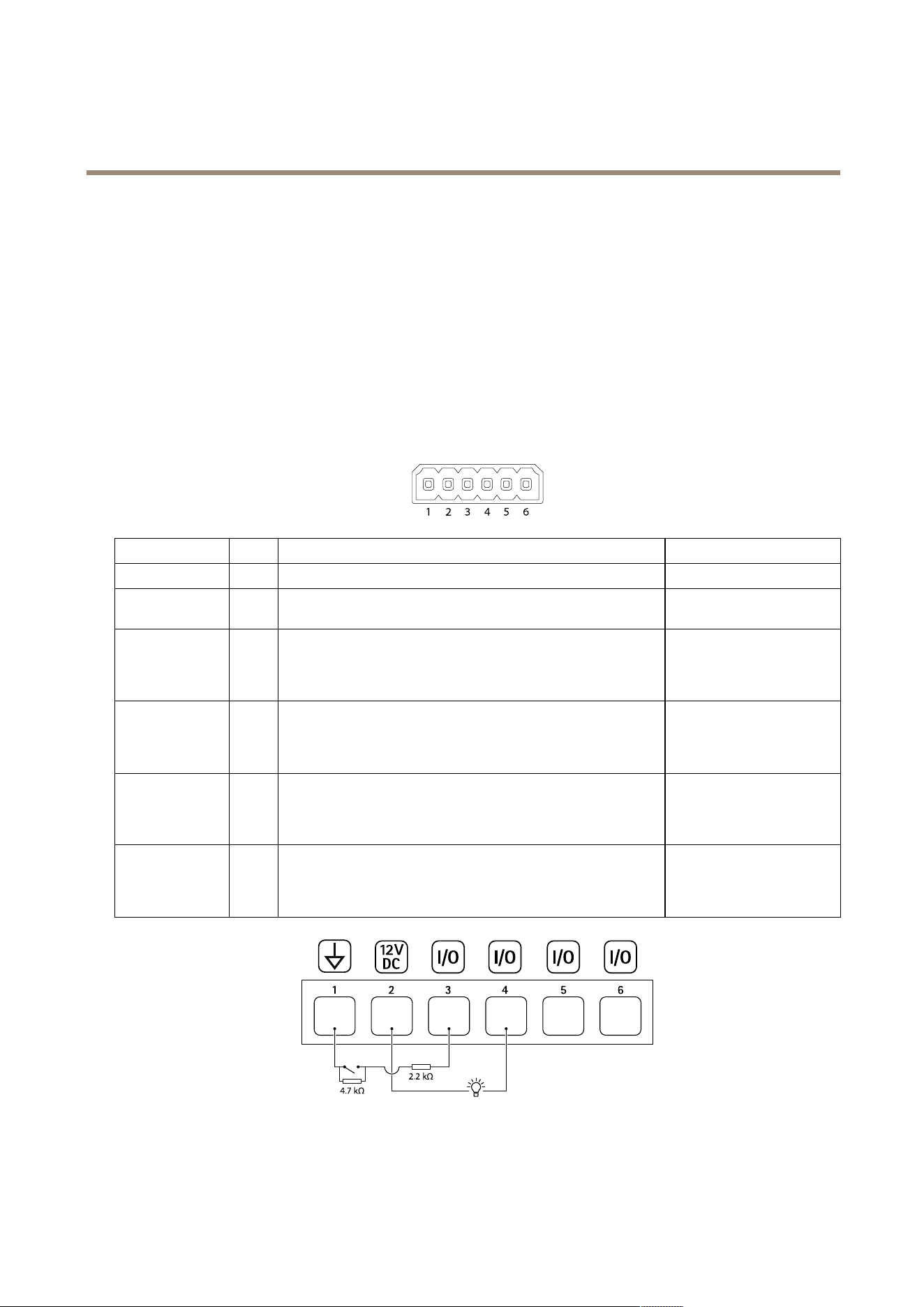
I/Oconnector
UsetheI/Oconnectorwithexternaldevicesincombinationwith,forexample,motiondetection,eventtriggering,andalarm
notications.Inadditiontothe0VDCreferencepointandpower(12VDCoutput),theI/Oconnectorprovidestheinterfaceto:
Digitalinput-Forconnectingdevicesthatcantogglebetweenanopenandclosedcircuit,forexamplePIRsensors,door/window
contacts,andglassbreakdetectors.
Supervisedinput-Enablespossibilitytodetecttamperingonadigitalinput.
Digitaloutput-ForconnectingexternaldevicessuchasrelaysandLEDs.ConnecteddevicescanbeactivatedbytheVAPIX®
ApplicationProgrammingInterface,throughaneventorfromthedevice’swebinterface.
FunctionPinNotes
Specications
DCground
1
0VDC
DCoutput
2
Canbeusedtopowerauxiliaryequipment.
Note:Thispincanonlybeusedaspowerout.
12VDC
Maxload=50mA
Input1
3
DigitalinputorSupervisedinput–Connecttopin1toactivate,or
leaveoating(unconnected)todeactivate.Tousesupervisedinput,
installend-of-lineresistors.Seeconnectiondiagramforinformation
abouthowtoconnecttheresistors.
0tomax30VDC
Output1
4
Digitaloutput–Internallyconnectedtopin1(DCground)when
active,andoating(unconnected)wheninactive.Ifusedwithan
inductiveload,e.g.,arelay,connectadiodeinparallelwiththeload,
toprotectagainstvoltagetransients.
0tomax30VDC,opendrain,
100mA
Input2
5
DigitalinputorSupervisedinput–Connecttopin1toactivate,or
leaveoating(unconnected)todeactivate.Tousesupervisedinput,
installend-of-lineresistors.Seeconnectiondiagramforinformation
abouthowtoconnecttheresistors.
0tomax30VDC
Output2
6
Digitaloutput–Internallyconnectedtopin1(DCground)when
active,andoating(unconnected)wheninactive.Ifusedwithan
inductiveload,e.g.,arelay,connectadiodeinparallelwiththeload,
toprotectagainstvoltagetransients.
0tomax30VDC,opendrain,
100mA
1
DCground
2
DCoutput12V,max50mA
3
Supervisedinputport1
66
Loading ...
Loading ...
Loading ...