Loading ...
Loading ...
Loading ...
33
35
34
36
71
46
45
9
71
45
46
71
59
45
13
8
2
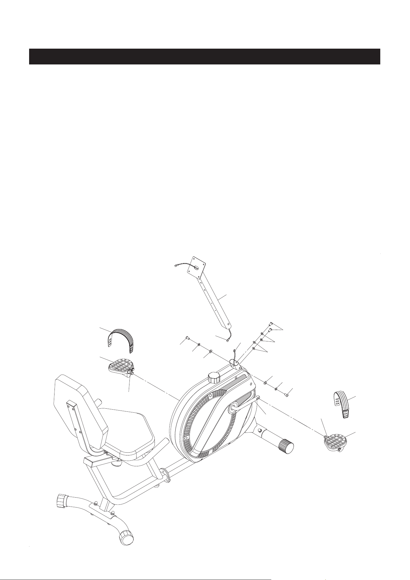
ASSEMBLY INSTRUCTIONS
STEP 7
NOTE: The RIGHT PEDAL(34) has an R stamped on the end of the pedal shaft. The RIGHT PEDAL(34)
has right hand threads and is tightened by turning clockwise. The LEFT PEDAL(33) has an L
stamped on the end of the pedal shaft. The LEFT PEDAL(33) has left hand threads and is tightened
by turning counterclockwise.
Thread the RIGHT PEDAL(34) into the right side of the CRANK(13) as shown. Tighten the pedal securely.
The shoulder of the PEDALS(33, 34) should be in contact with the CRANK(13) when securely tightened.
Select the RIGHT PEDAL STRAP(36) which has an R marked on it. Snap the three hole end to the inside
edge of the RIGHT PEDAL(34). Snap the other end of the strap to the hook on the outside edge of the
RIGHT PEDAL(34). Select adjustment holes which allow your foot to be easily removed from the pedals.
Use the same procedure to attach the LEFT PEDAL(33) to the CRANK(13) and to attach the LEFT PEDAL
STRAP(35) to the LEFT PEDAL(33).
STEP 8
Connect the EXTENSION WIRE(8) to the SENSOR WIRE(9). Insert the UPRIGHT(2) onto the FRONT
FRAME(1) and secure with BUTTON HEAD BOLTS(M8x1.25x20mm)(45), LOCK WASHERS(M8)(71),
WASHERS(M8)(59), and ARC WASHERS(M8)(46).
10
Shoulder
Shoulder
Loading ...
Loading ...
Loading ...