AQUIFER 200 & 360 EXPEDITION “FLIGHT READY”
OWNER’S MANUAL
Instrucons also included for the Oponal Solar Power Unit
Katadyn Desalination, LLC
Manufacturer of Spectra Watermakers
PH 415.526.2780
FX 415.526.2787
www.spectrawatermakers.com
Revised April 2023

2

3
Table of Contents
Introduction Page Number
Getting Started ......................................................................................................4
Hose Connections .................................................................................................6
Solar Power Pack & Universal Voltage kit .............................................................8
Well Pump Connections ...................................................................................... 12
Aquifer Plumbing Diagram .................................................................................. 14
Operation
New Systems Start Up and Testing..................................................................... 16
Operation ........................................................................................................... 17
Maintenance ........................................................................................................ 23
Service & Maintenance
Long Term Storage ............................................................................................ 20
Winterizing .......................................................................................................... 22
Membrane Cleaning ............................................................................................ 25
Suggested Spares ............................................................................................... 26
Troubleshooting Procedures, Service Bulletins ................................................... 27
Wiring Diagram…………………………………………………………………….…...29
Fitting details ....................................................................................................... 31
Parts breakdown ........................................................................................................... 35
4
Unpack the system and inspect it to make sure that it has not been damaged in
shipment.
Refer to the shipping list for your system to make sure you have received all of the
components listed. Do not discard any packaging until you have found and identified
all of the parts. The small installation parts are listed on the kit list. Warning! We will
not be held responsible for shortages and or freight damage that are not
reported within thirty days of the ship date.
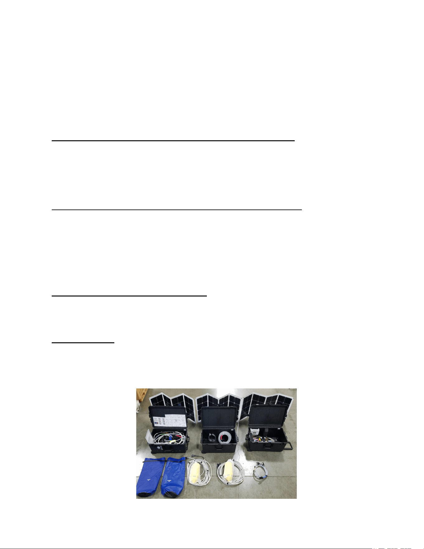
Getting Started
Aquifer 200 Expedition Shipping List (One Pelican Case)
• Aquifer Portable Watermaker including one Submersible Well Pump with Hose and
Power Cable (25’)
• 5/8” Discharge Hose (25’)
• 1/4 product tubing (10’)
Aquifer 360 Expedition Shipping List (Two Pelican Cases)
• Aquifer Portable Watermaker
• Second Pelican case with two Submersible Well Pumps with Hose and
Power Cables (25’)
• Pump connector (two pumps into one connector)
• 5/8” Discharge Hose (25’)
• 1/4 product tubing (10’)
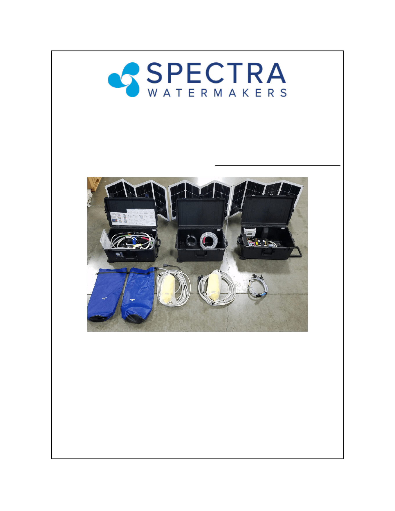
(Optional) Aquifer Solar Power Pack
• Solar Power Pack (in a separate Pelican Case)
• Two solar panels for the AF-200 and three solar panels for the AF-360
Optional Items
• Case of 25 prefilters (fit in the Aquifer 360 pump case as shown in photo below)
• AC power supply (installed in the watermaker box) for units that do not come with
the Solar Power Pack
5
Getting Started Continued…
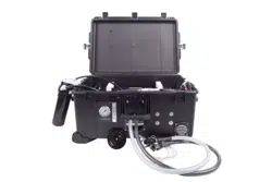
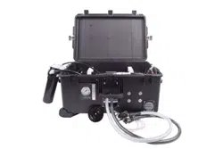
The Spectra Aquifer Expedition systems come fully assembled and ready for use. All
connectors are marked for easy identification. The submersible pumps plug directly
into the 24vdc power supply.
Placement Ideally the system should be stored and used in a cool, dry, location within
20’ of the feed water source. The system comes with 25’ of intake hose attached to
each of the submersible well pumps. The case is splash resistant, but not water tight
and the unit should be stored with the lid open until any water in the case has
evaporated. Choose a location where any water spilled during filter changes will not be
a problem. If the unit is to be installed in a mobile vehicle, it should be strapped down
to keep it in place.
Feed Water The Aquifer Expedition is designed to be operated up to 20 feet above the
waterline.
Brine Discharge Install the female quick disconnect fitting in the brine discharge hose
and route it back to the feed source away from the pump(s). If a well is the feed source
then discharging on the ground away from the well is advised.
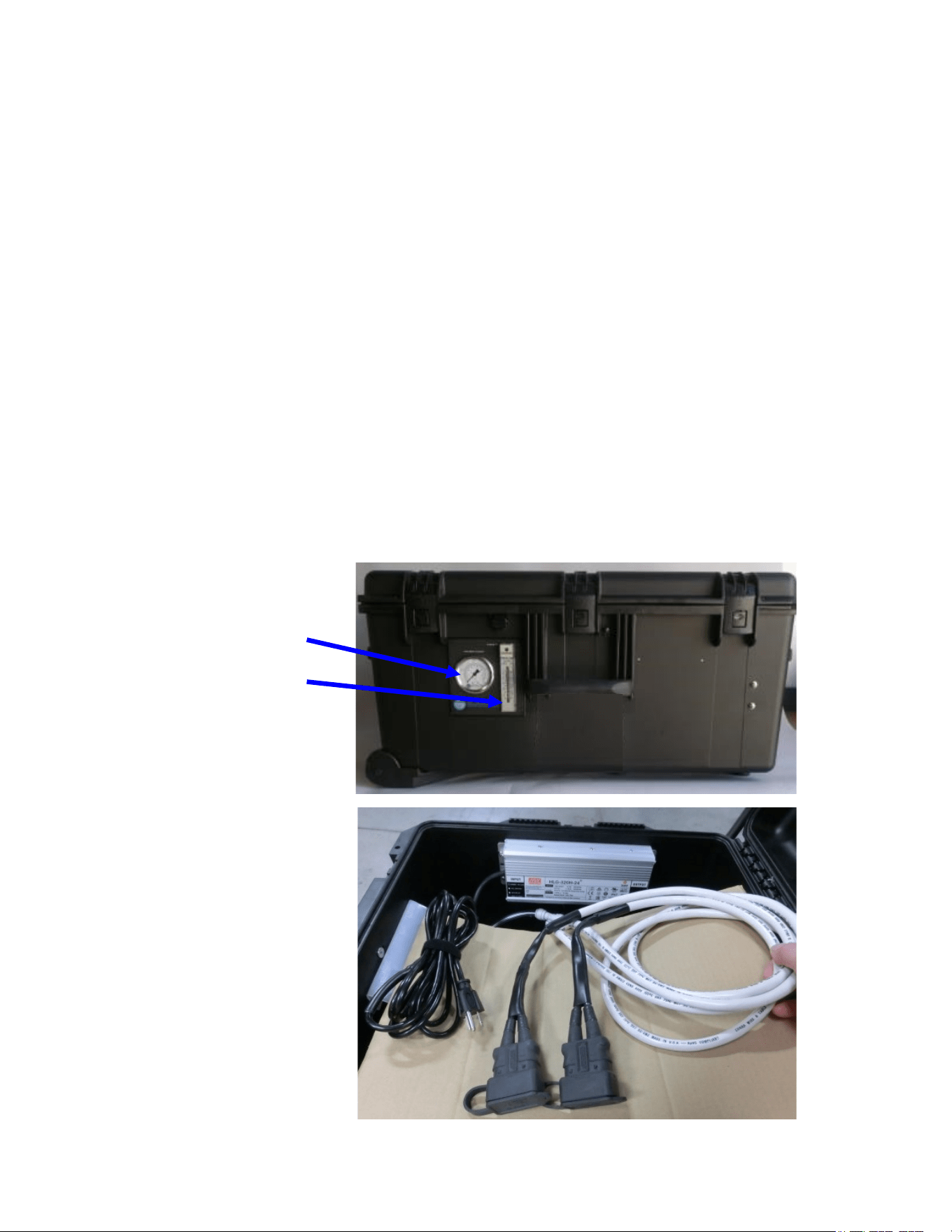
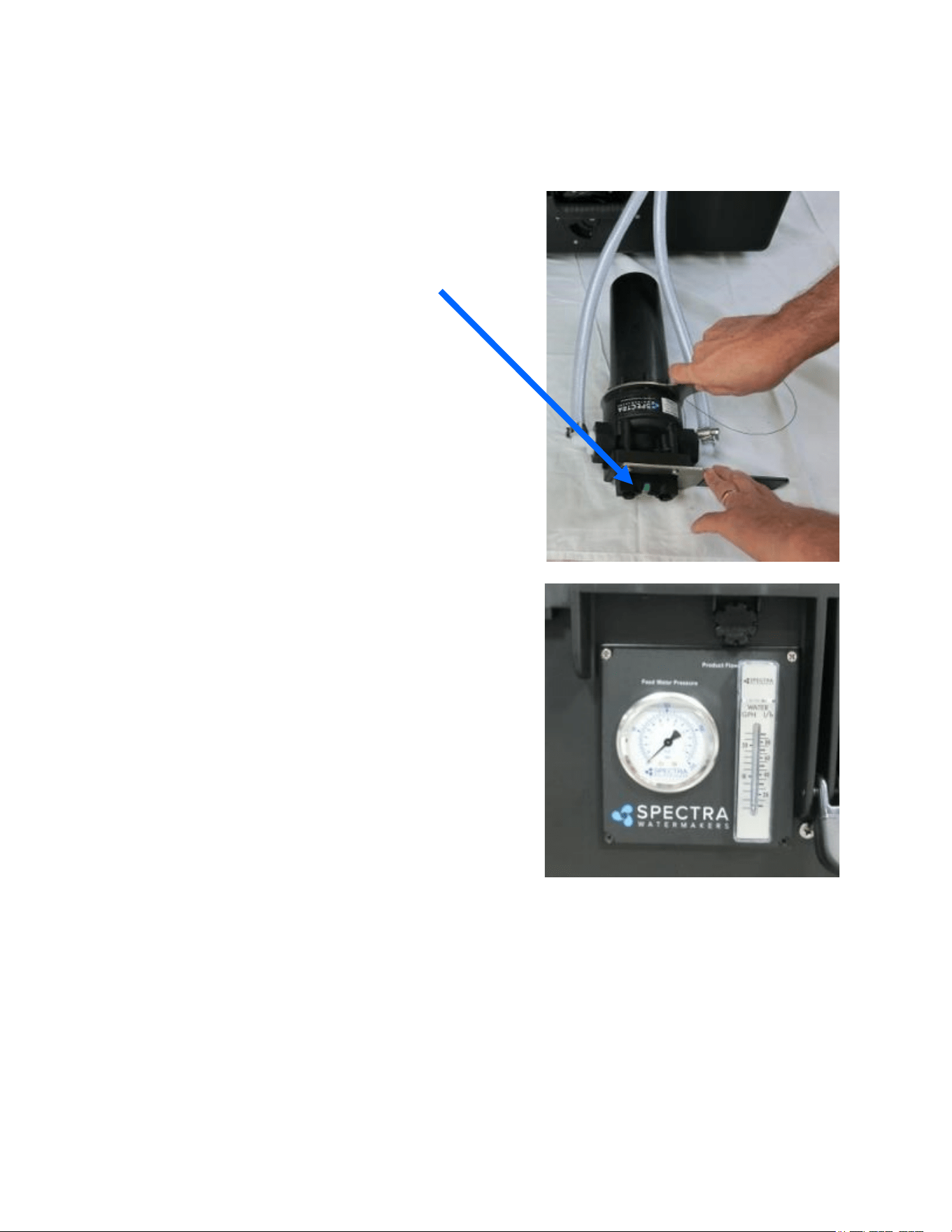
Feed Pressure Gauge
Product Flow Meter
Note: Systems without
the Solar Power
supply can be ordered
with a 100-300vac
50/60 Hz AC power
supply installed in the
watermaker box.
The Aquifer 200 will
only have one 24VDC
connector as it has
only one feed pump.
Either system will also
run on an external
24 vdc power source.
6
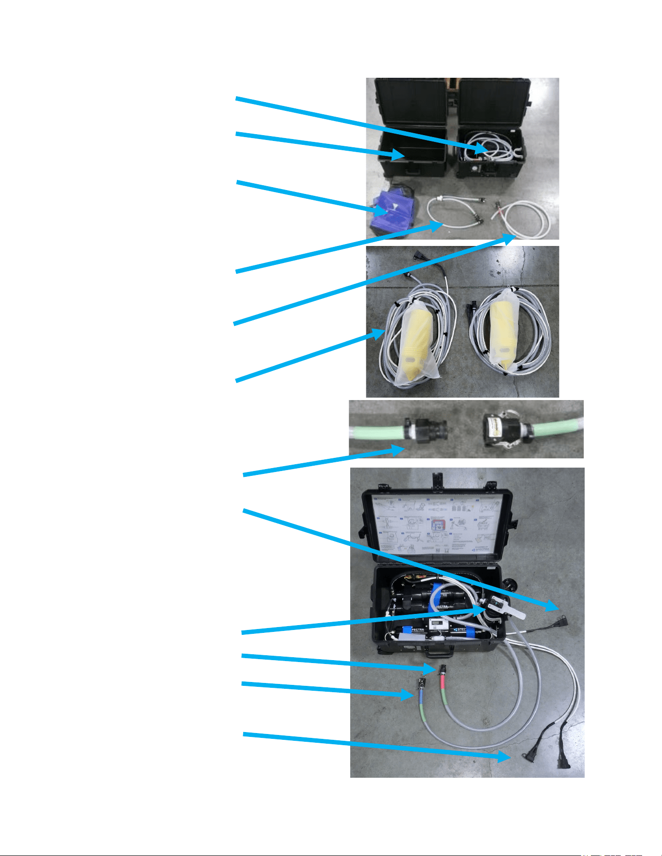
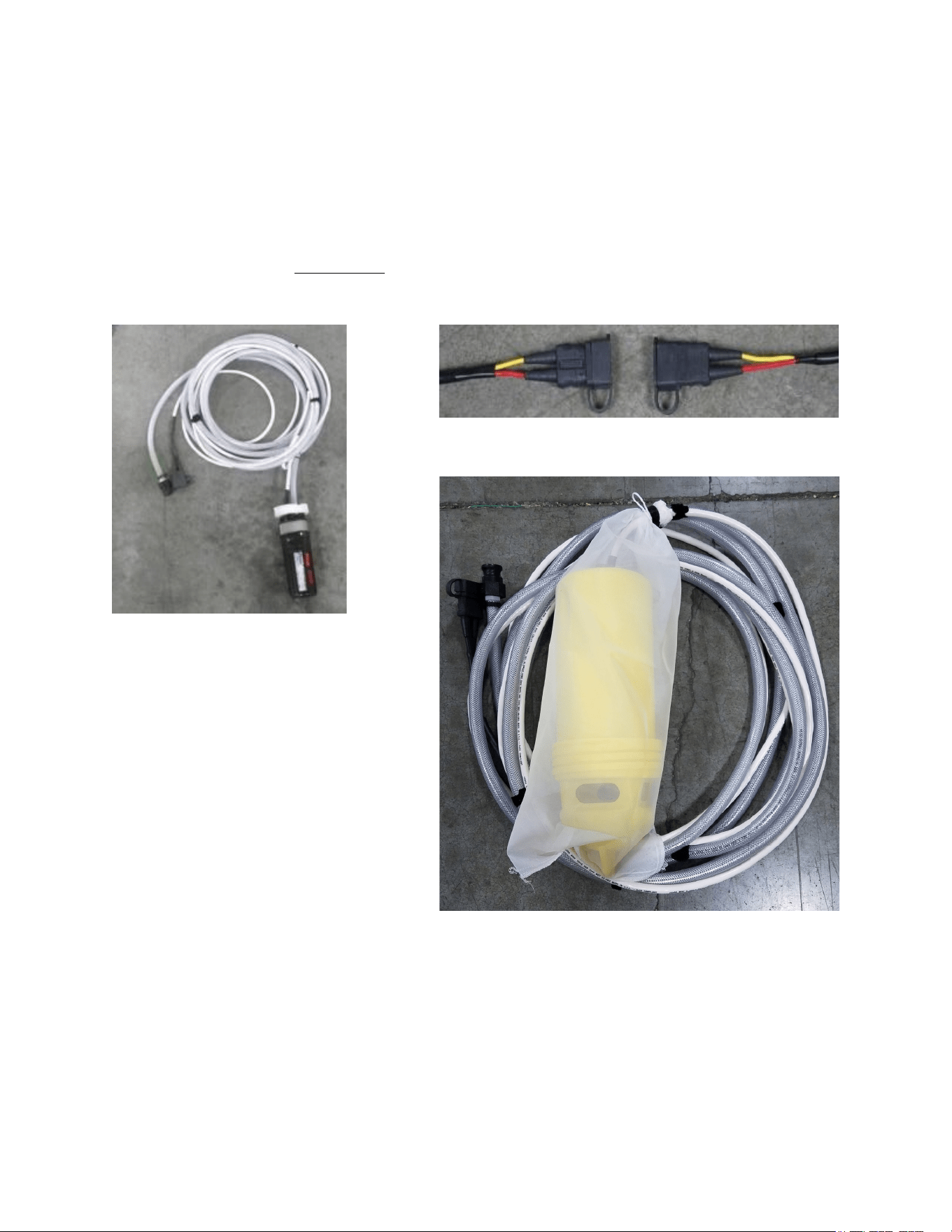
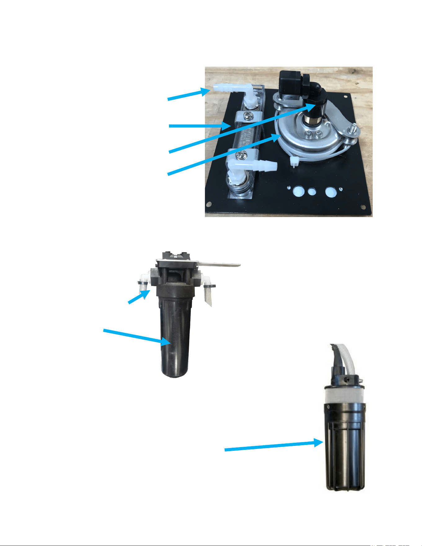
Aquifer Expedition Hose Connections
Brine Discharge - Discharge
to a nearby drain site
according to local regulations
Watermaker Case
Quick connect fittings
Connection to Options Solar
power supply
5 micron filter with gauge
Brine discharge hose
Feed Water connection
Connect to pumps
(AF-200 unit has one pump
and the AF-360 has two)
Feed water hose - connects
directly to the feed pump
connector.
Case for pumps and hoses
Pump connector hose -
connects directly to the feed
pumps .
Pump storage bags - Use
when storing the pumps wet.
Not for long term storage.
Note that all hoses are color coded
except for the product hose which is
clear
.
7
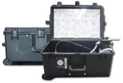
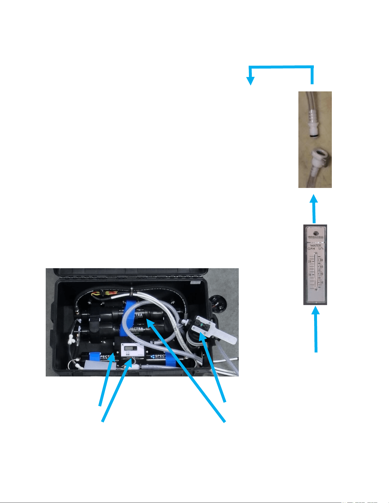
Aquifer Expedition Hose Connections
Product
Flow
meter
Product Outlet
Warning!
Pressure in the product tubing must
never exceed 5psi (0.3bar) at any time or
the membrane will be permanently
damaged. The product water should fall into
the storage tank through an air gap so there
is no back pressure on it. DO NOT! feed the
product into a manifold or the bottom of a
tank. Make sure that there is no possible
restriction in the product hose or
connections.
Note: The product flow meter displays the
flow per hour. In normal operation the flow
will go up and down as the Clark Pump
Shifts.
It is a good idea to keep a record of the flow
rate and system pressure so you
understand system performance. This data
will inform any future maintenance or
service requirements.
Clear product
water
tubing with
quick-
connects
Clark Pump
Salinity Gauge
Product Water
Product water
from membrane
via clear 1/4”
hose
Prefilter with
gauge
Membranes
8
Optional Aquifer Expedition Solar Power Pack
This system handles universal voltage inputs and will operate on both AC and DC
power sources;
• 100—240 vac 50-60Hz (using a standard US 110vac plug)
• Solar power from the three 145watt solar panels
• 12 vdc to input terminals (jumper cables)
• 24vdc to input terminals (jumper cables)
Solar Charge Control
AC Power Supply
The Solar Charge Control will display the power coming in, the battery voltage and
the power being used. When the batteries are fully charged the input Amps will drop
to below 1. Note that the load will disconnect (the pumps will stop if the battery
voltage the battery voltage drops to about 25 volts (this is to protect the battery pack
from over discharge). Once the battery voltage comes back up to about 26.5 volts the
pumps will start again. If there is not full sun the system may cycle on and off as the
battery drains and the input from the solar panels is not high enough to run the
system.
Power Input
(no input shows a moon,
with input there will be a sun)
Battery Voltage
Power draw from
pumps in Amps
9
Optional Aquifer Expedition Solar Power Pack
Note that the pumps can be plugged in or unplugged at any
time. This is a low voltage DC system and there is no
problem with unplugging or plugging in the pumps under
load.
The Solar Panels are “daisy chained” together and it
is not possible to connect them incorrectly.
• Connect the center panel to the panels on each
side and then connect the remaining plugs to the
cables from the power supply.
• The solar panels work best when the sun is
directly over them so it will help if the panels can
be set up at an angle so they are pointing at the
sun.
The system can also be powered with jumper cables
from either a 12 VDC source (car or truck) or a 24 VDC
military vehicle. Remove the rubber boots to expose
the jumper cable studs.
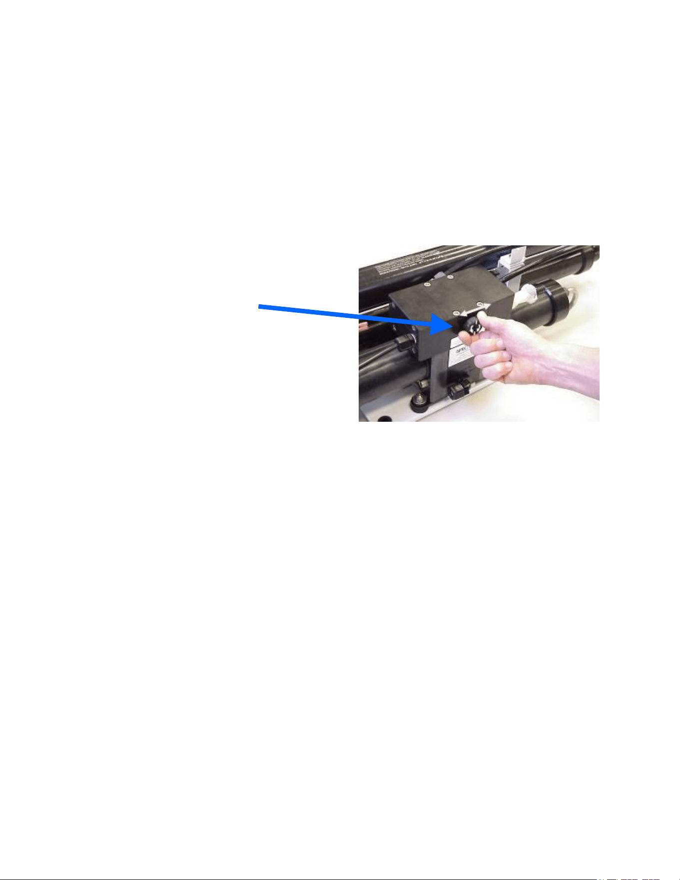
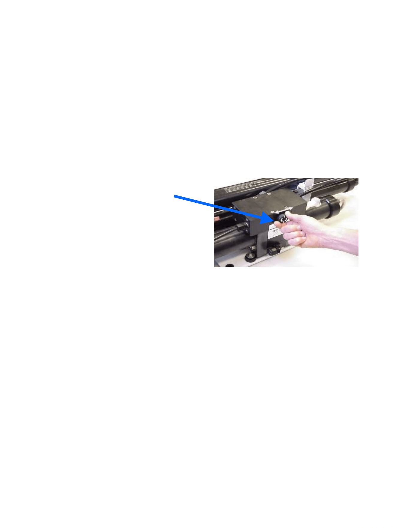
Battery On/Off
Input Power source selector switch
There is a detailed description of
the selector switch function in the
Power Selection Guide on the next
page.
10
11
12
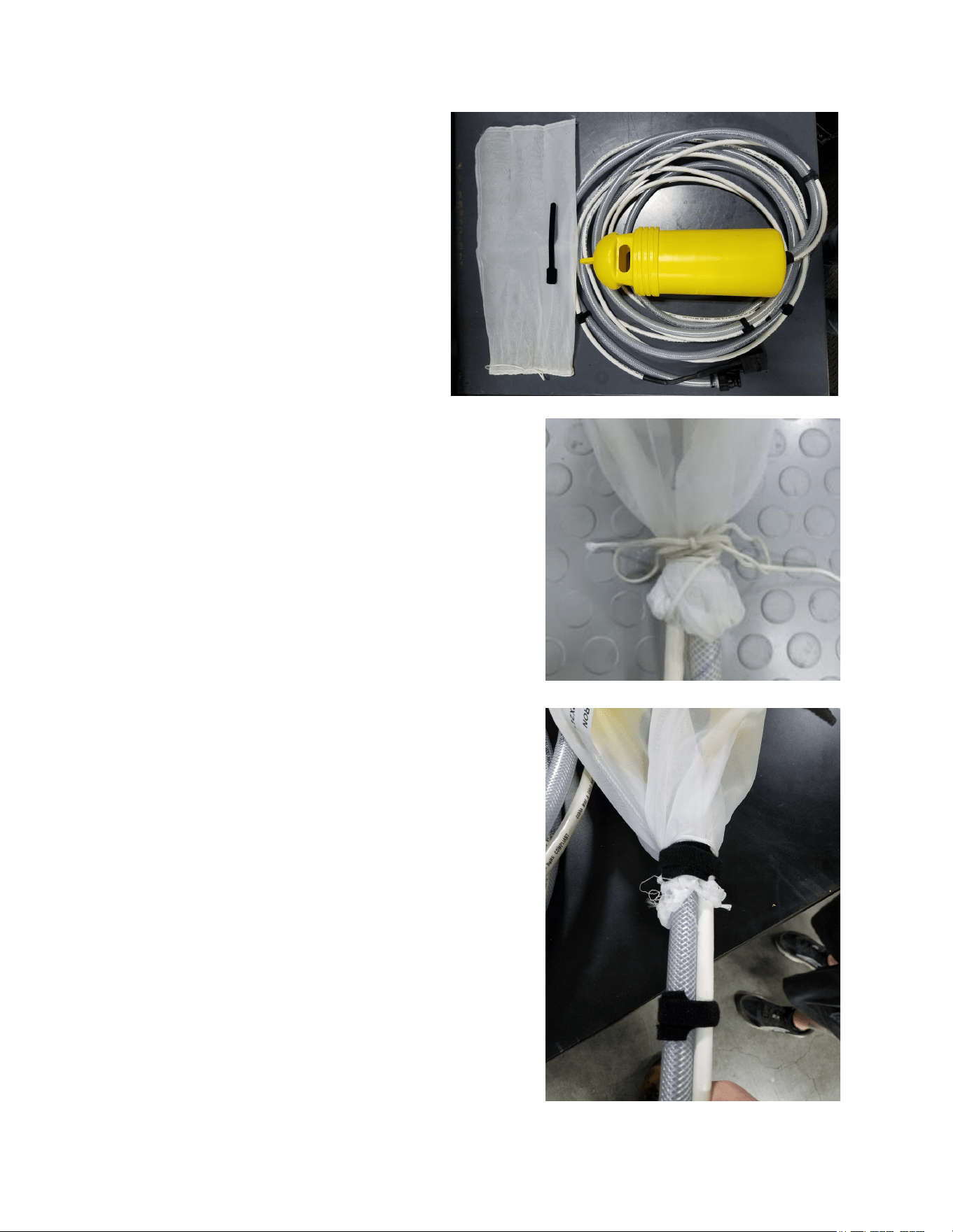
Aquifer Expedition Well Pump Connections
There is no on/off switch on the system as it is not required, just plug the power cord on
the pump into the power cord coming from the unit.
When not in use keep the dust caps in place on the plugs to keep them clean. Clean
connectors work much better.
When plugged in, the connection is water resistant (not water proof) so be sure it is
never submerged in water.
13
Aquifer Expedition Well Pump Connections
The 100 Micron Filter Bag’s primary
purpose is to extend the life of the
prefilters.
It also serves to keep the lid of the well
pump case in close proximity should it
accidently become separated from the
body of the case.
If the 100 Micron Filter Bag becomes clogged or
dirty, simply remove the Velcro strap and untie the
bag and leave to dry in the sun for at least 3 hours.
The sun will kill any lingering bacteria clinging to
the bag from the ocean or brackish well.
Next, wrap the Velcro strap around the loose ends
so it will not come untied.
14
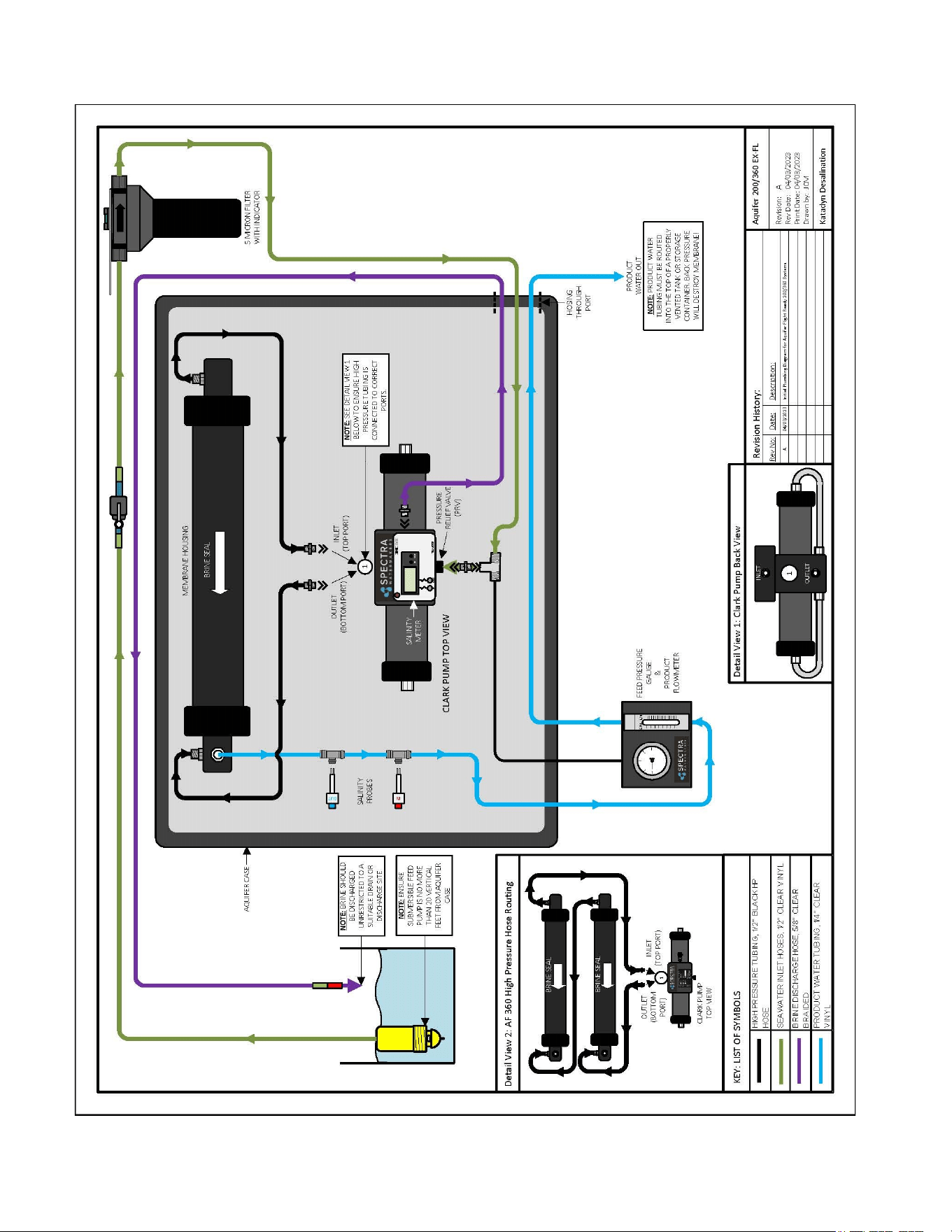
Aquifer 200/360 Plumbing Diagram

15
Notes
16
Aquifer New System Start-Up and Testing
Warning! Your watermaker shipped from the factory with a non-toxic
preservative to protect the internal membrane. Damage will occur if this
preservative is not flushed properly and the membrane is pressurized
with preservative in it.
DO NOT OPERATE the Aquifer system if the feed water contains oil as oil will foul the
membrane.
1. First:
• Any feed water; salt, brackish, or fresh water will work for purging storage chemicals. You
will need at least 50 gallons (200 liters) of unchlorinated water. If only chlorinated water
is available, replace the 5 micron filter with a Charcoal Filter element during the flush
to remove chlorine.
• Connect the feed, brine, and product hoses. Place the submersable pump into the feed
water source far enough below the surface to prevent air from being pulled in. Place the
end of the brine hose so that the brine does not mix directly back in with the feed water.
• Install the product hose and place the end of it so that any product will be discarded for the
first 5-10 minutes of operation (after purging storage chemicals)
• Ensure that the pressure relief valve is open a 1/2 turn.
• Connect to a power source, 100 to 240vac, 12 or 24vdc using the marked terminals
2. Plug the feed water pump into the power cable. Note that there is no on/off switch, when you
plug the pump in the unit will run. Check that ithe pump is submerged by inspecting the brine
discharge for bubbles. About 1.5 gpm (6 lpm) of water should be being discharged with a
(normal) pulsation every few seconds.
3. Run the system without pressure for at least 20 minutes to purge the storage chemicals, or at
least an hour if stored with propylene glycol. The system should have an open flow
pressure on the gauge of about 20 PSI (1.2 bar). Note that water may drip from the product
tube.
4. When the above purge cycle is completed, close the pressure relief valve and the pressure
will increase. After several minutes, water should begin to flow out of the product water tube.
5. Allow the system to run for 5-10 minutes to purge the product water of preservative, and then
test the product with your handheld salinity tester. When the product is below 750 PPM it is
considered potable and may be diverted to the water container for human consumption.
Open 1/2 Turn and Purge System Remove Tag and Washer!
17
Aquifer Expedition Operation
Normal operation
If the system has been pickled or stored or contains cleaning compounds, use the “New
System Startup” procedure.
1. Connect all the hoses per the color codes; blue is for the feed pumps and red for the
discharge. The green hoses are connected for storage or shipping.
2. Check to see that the intake screen on the Submersible Pump is completely submerged in
the source water. If using the float it may be helpful to place a rock on the hose to keep the
pump in place.
3. Set up the product tubing so that the product is being discarded and it can be sampled.
4. Open the pressure relief valve, plug in the well pumps, turn them on with the selector
switch on the power supply and check for flow by inspecting the brine discharge or
checking for pressure on your pressure gauge.
5. When there is flow from the discharge tighten the pressure relief valve and check the
product water quality. When it is below 750 ppm, you may divert it into your container.
6. Run the system until you have filled your tank or have made enough to meet your
requirements plus 5 gallons for flushing the system.
7. Make about 5 gallons of water in one of the waterproof bags or a bucket to be used to flush
the salt water out of the watermaker. Use only unchlorinated water for flushing.
8. Place the submersible pump in the bucket upside down so the screen pick-up is as low as
possible and start the pump.
9. Flush until the pumps start to suck air and then stop the pumps.
10. Store the hoses inside the case and connect them together so no water drips in the case.
Ideally allow the inside of the case to dry completely before storing.
You may now leave the system unattended for up to five days without further attention
We recommend operating the system for longer periods to conserve flush water. Remember
that you need to run the system almost a half an hour to make the flushing water.
Be sure to rinse the feed pump(s) with fresh water after every use, cleaning the mesh strainer
in the process. It is recommended that everything be stored in a clean, dry place.
Submersible
Well Pump
Intake Screen and water inlet
18
Aquifer Expedition Operation, Continued….
When the system has been running for about 10 minutes, record the pressure reading
and product flow.
There are two things to monitor when operating the
system;
1. The Green/Red filter indicator on top of the filter
housing (Change filter when RED).
Note the filter can be placed on the ground to
loosen the filter bowl as shown.
If the filter bowl gets stuck have someone tap
on the housing (actually hit the label) with a
hammer while applying pressure with the
wrench.
2. If the pressure drops and the filter is still green
then the filter bag on the feed pump needs to be
cleaned.
• Turn the pumps off
• Pull each pump out and clean 100 Micron Filter
Bag (Use a hose or a running water source to
rinse off the bag until all visible debris has been
removed from the surface of the filter bag).
• If necessary, take the filter bag off the pump
and clean it more vigorously using water and a
scrubbing action to remove all visible debris that
might inhibit consistent waterflow to the pump
intake.
19
Aquifer Expedition Operation, Continued….
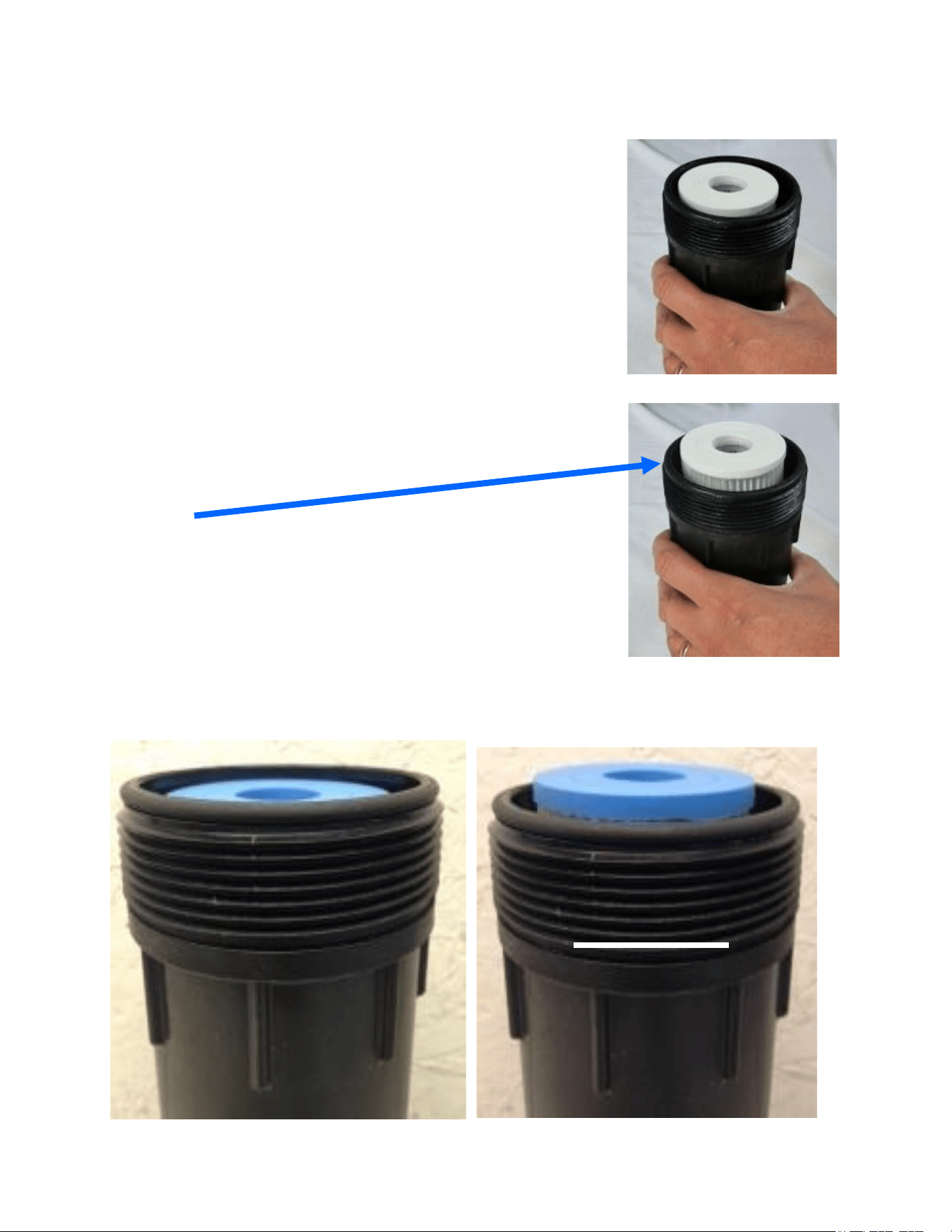
Filter Change
Rinse out the filter bowl and install a new filter
as shown.
Be sure the filter is seated and not sticking up
like this one.
O-ring
Run your finger around the O-ring on the top
edge of the filter bowl and be sure it is free of
dirt or debris.
YES
NO
20
Long Term Storage Procedures
Watermakers are best run continuously. When not in use, biological growth in the
membrane is the leading cause of membrane fouling. A warm environment will cause
more growth than a cold environment.
System Storage or “Pickling”
If the system is to be left unused for more than five days, perform the following storage
procedure. The procedure introduces a chemical compound into the system that
prevents biological growth. This procedure requires de-chlorinated water.
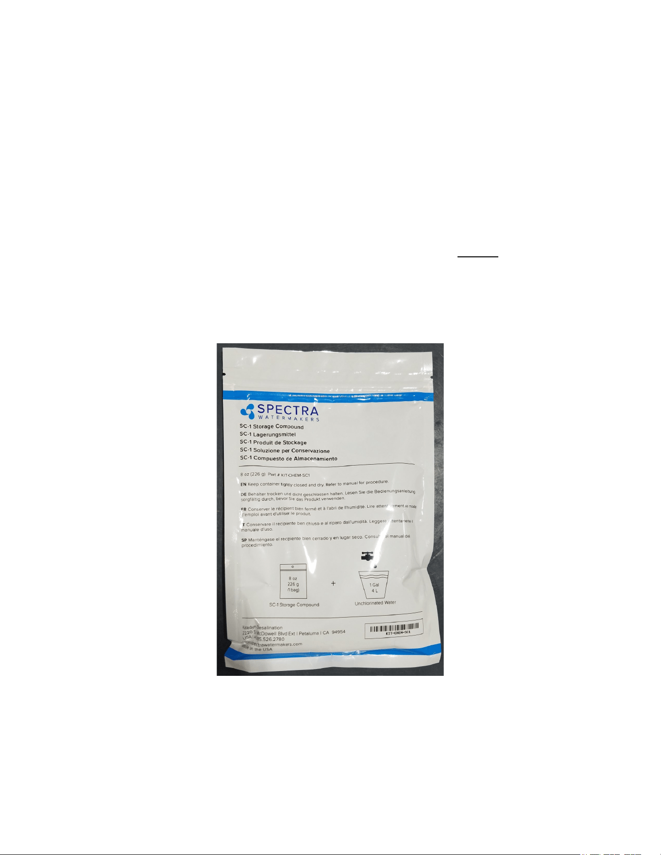
Spectra SC-1 is a special storage compound used by the US Navy. It is
formulated to be compatible with the modern engineering plastics and
composites in the Spectra pumps. Do not use any substitute except propylene
glycol. If you wish to use glycol for storage, follow the winterizing instructions.
SC-1 Storage Compound has to be mixed at a ratio of 1 container to 3 gallons
(12L) of fresh water to have the proper solution for short term storage.
Caution! Avoid contact with skin, eyes, or breathing the storage chemical.
21
Aquifer Expedition Storage Procedure
1. Perform a fresh water flush as described in the Normal Operation section. Leave
one gallon of water in the bucket.
2. Place the brine discharge in the bucket.
3. Add one packet of SC-1 storage chemical to the bucket and stir until mostly
dissolved. The chemical will dissolve in about an hour, but don’t worry if it doesn’t
all dissolve, it will not hurt the pump.
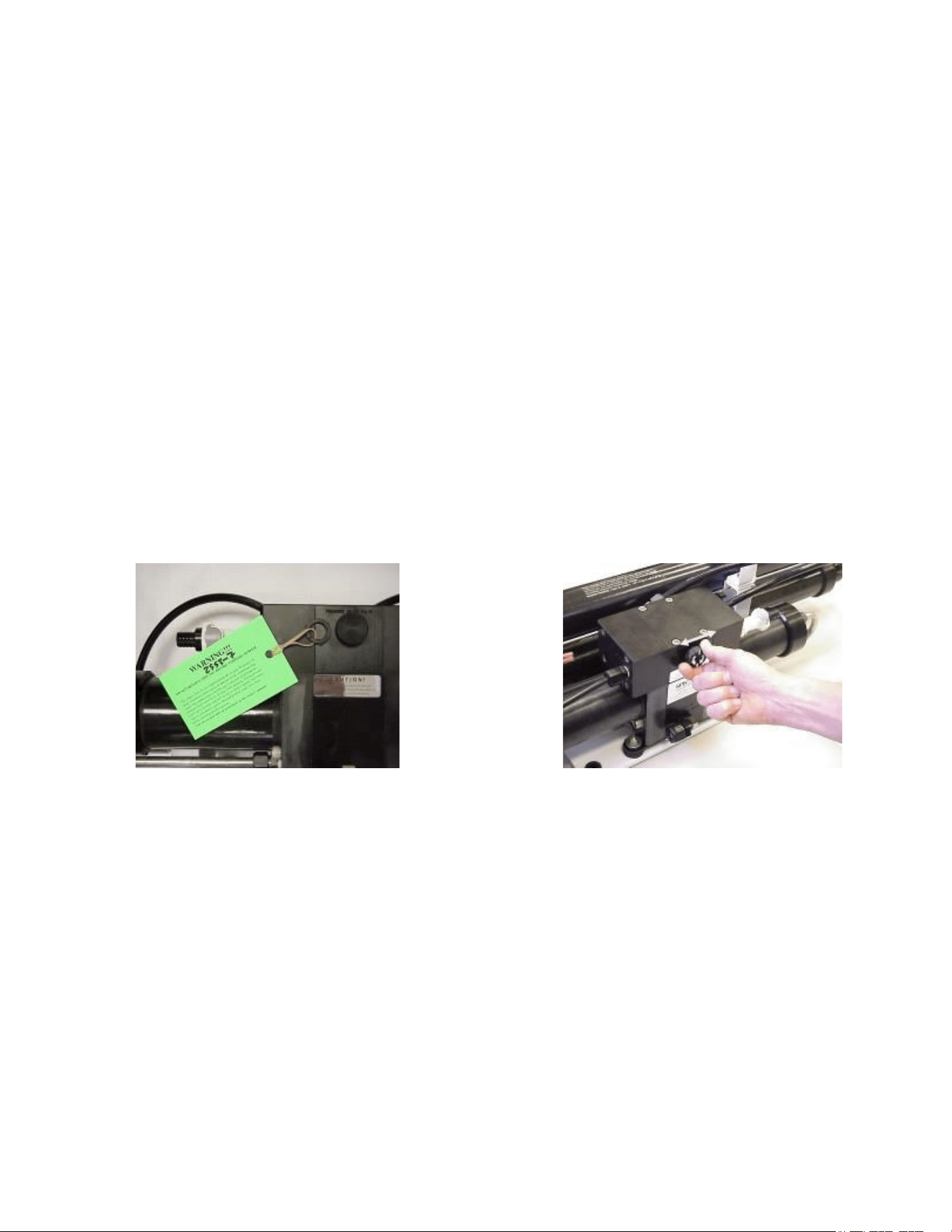
4. Make sure the pressure relief valve on the Clark Pump is OPEN
(unpressurized) by unscrewing it
1
/
2
turn counterclockwise.
6. Start and run the well pump to circulate
the solution for about ten minutes.
7. Stop the well pump.
Leave the pressure relief open.
Clean Up
• Drain hoses as much as possible so
there is no water to drip inside the case
when the unit is stored.
• Disconnect the electrical connections and remove and stow the product tubing if
the unit is to be transported.
• Remove hoses and stow it away in the case (connect quick fittings so any water in
the hose is captured.
• Remove the pre-filter from its housing and replace with a clean dry filter element.
• Clean and dry the submersible well pump and stow inside the case.
• Allow the interior of the case to dry out if possible before storing.
22
Pickling and Winterizing with Potable Water Antifreeze
Do not use Potable Water Antifreeze
that contains Ethyl Alcohol
The watermaker can be stored for any period up to one year in any climate using
this procedure.
1. Perform a fresh water flush as described in the Normal Operation section.
2. Empty the bucket of water. There is one gallon of water in the system so add enough Low
Temperature Propylene Glycol Potable Water Antifreeze into the bucket to obtain the freeze
protection required following the chart on the bottle.
3. Make sure the pressure relief valve on
the Clark Pump is OPEN
(unpressurized) by turning it
1
/
2
turn
counterclockwise.
5. Start and run the Well Pump until
antifreeze begins to come out of the Brine
Overboard Hose.
6. Stop the Well Pump. Connect the brine
service hose to the brine outlet on the
Aquifer case and place it in the bucket.
7. Start the well pump and circulate the
remaining antifreeze for a few minutes until
well mixed.
8. Stop the well pump and discard any antifreeze remaining in the bucket.
9. Blow out or drain the product tubing, as it will not contain antifreeze.
10. Leave the pressure relief open.
Clean Up
• Drain hoses as much as possible so there is no water to drip inside the case when the unit is
stored.
• Disconnect the electrical connections and remove and stow the product tubing if the unit is
to be transported.
• Remove hoses and stow them away in the case (connect quick fittings so any water in the
hose is captured.
• Remove the pre-filter from its housing and replace with a clean dry filter element.
• Clean and dry the submersible well pump and stow inside the case.
• Allow the interior of the case to dry out if possible before storing.
23
Maintenance
General
Periodically inspect the entire system for leakage and chafe on the tubing and hoses.
Repair any leaks you find as soon as practical. Some crystal formation around the
Clark Pump blocks is normal. Wipe down any salt encrusted areas with a damp cloth.
If any rust appears at the Stainless Steel fittings, clean them up promptly.
Keep the inside of the case dry and salt free.
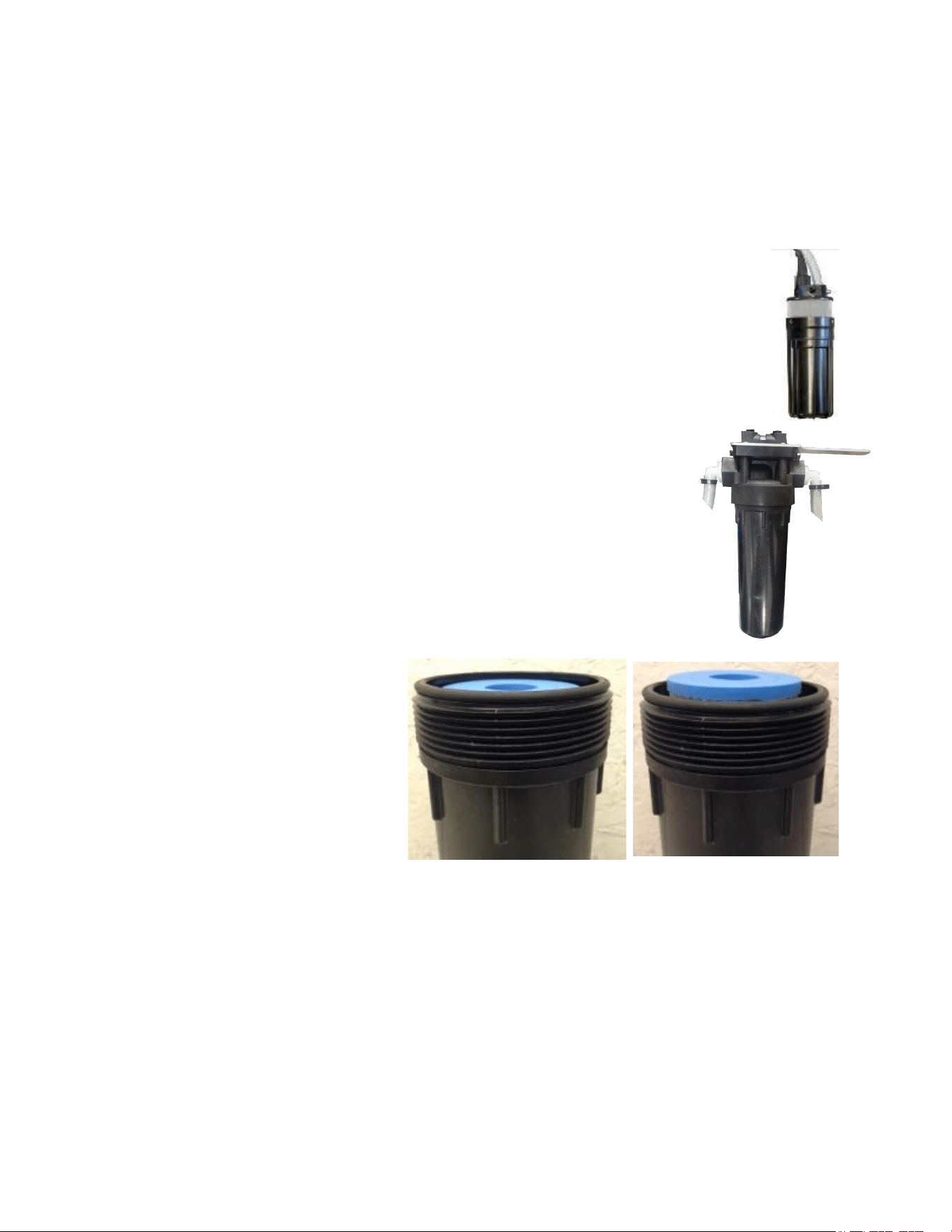
The Submersible Well Pump
The Aquifer Expedition comes with a unique submersible diaphragm pump
with an integrated seawater strainer. After each run cycle the well pump
should be fresh water flushed, cleaned and stored dry to avoid premature
damage. When the system is put into storage, remove, rinse, and dry the
pump to impede corrosion. Check frequently during operation.
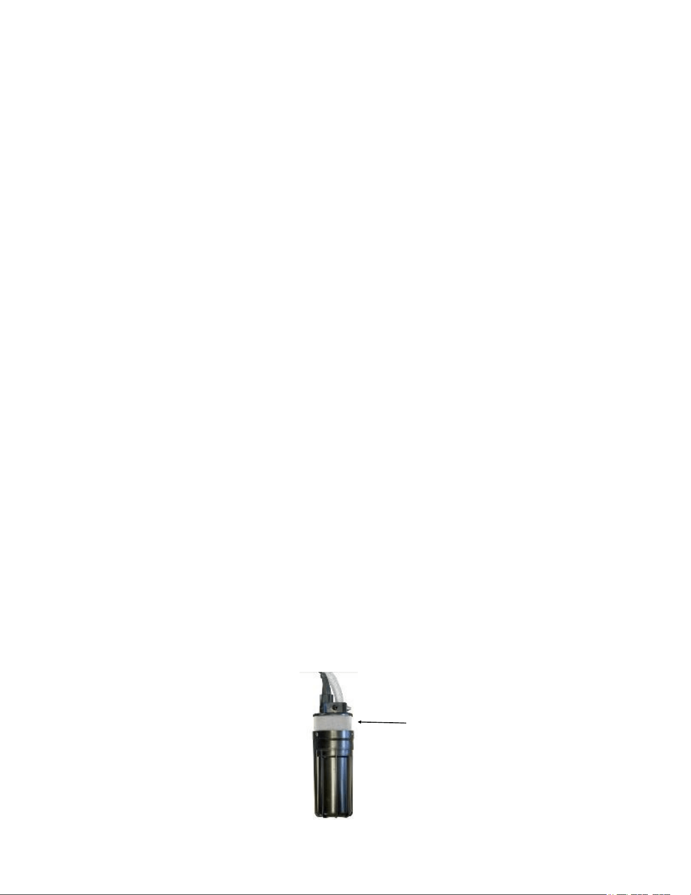
The Pre-filter
Service the pre-filter on a regular basis. When the pressure drops
more than 5 psi on the gauge the filter becomes dirty. Do not leave
dirty filters in the machine during long idle periods, as biological
contamination could result.
To service the filter, swing the housing out of the case, open the
housing using the supplied filter wrench, and discard or clean the
old filter.
Clean out the housing bowl,
reassemble the housing with a
new 5 micron filter element.
Leave dry until next startup.
Use only Spectra approved
filters or you may void your
warranty. The filter may be
cleaned a limited number of
times by soaking it in water in a
bucket and then letting them
dry completely. Occasionally,
lightly lube the filter housing O-
ring with silicone grease.
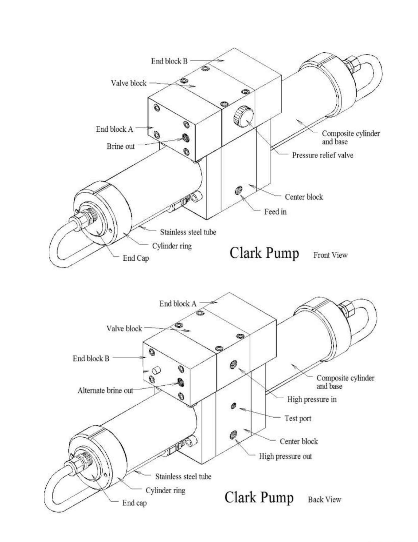
The Clark Pump
The Clark Pump requires no routine maintenance except inspection for leaks. Tighten
any hose clamps or fittings the show signs of leakage. The high pressure fittings
threaded into the Clark Pump have O-ring seals with a straight thread. These should
never leak and should never be over tightened. If one of the tube nuts starts to leak, it
can be un-threaded, sealed with a bit of silicone grease or silicone seal, and tightened
with two wrenches very tightly.
YES
NO

24
Membrane Cleaning
For normal cleaning, the SC-3 Acid Cleaning Compound is used first, then the SC-2 Alkaline
Cleaning Compound. If known bio-fouling is present (rotten egg smell) the SC-2 may be used
first. Using hot water if possible, up to 120° (45C) is recommended as it greatly enhances the
ability of the cleaners to do their jobs.
If the history of the system is unknown or it has been left “unpickled” for an extended length of
time and biological growth is present, it is recommended that the system is cleaned with SC-2,
using an alternate source of unchlorinated fresh water before the system is run under
pressure. A simple test can be performed to see if biological growth has occurred. Before
running the system, remove the prefilters and examine their condition. If the housings are full
of smelly discolored water, the system was not properly stored. Install clean prefilters if they
were bad. Next check the membrane. Attach the brine service hose and lead it to a bucket.
Open the pressure relief valve one turn, and run the system for 30 seconds. Examine the brine
water: if it’s discolored and smells bad, perform an SC-2 cleaning with an alternate source of
unchlorinated water before running the system pressurized. If the brine is fairly clean, the
system can be purged, run normally, and checked for performance. Clean the membranes only
if performance is reduced.
Heating the water is preferable. One way to do this is to find a camp stove and use a large
stainless steel pot to heat the solution in. The cleaning solution throughout the system will heat
as it circulates in and out of the pot. An alternative is to heat the one or two gallons of initial
water to 120° on the main stove before mixing in the cleaner and circulating it into the system.
Periodically stop and reheat the solution.
Perform the cleaning procedures and then test on a normal feed water supply.
The membranes need to be cleaned only when feed pressure begins to rise due to fouling or
the product quality degrades. The leading cause of fouling is from biological growth that occurs
when the system is left unused without flushing or pickling. Fouling from mineral scaling can
happen during operation under certain source water conditions, and from rust. Monitor the
product salinity and feed pressure for higher than normal readings for the existing conditions.
Other conditions can cause high pressure such as cold feed water or clogged filters.
Low product flow is usually due to low voltage, a damaged well pump, or Clark Pump
problems. Look for all other causes before cleaning the membrane as excessive cleaning
shortens membrane life.
There are two types of cleaners: acid and alkaline. The acid cleaner (SC-3) will remove mineral
scaling. The alkaline cleaner (SC-2) is used to remove biological by-products, oil, and dirt
particles that get past the pre-filter. If membrane performance is reduced and they have not
been “pickled” recently, cleaning with both chemicals is recommended. The acid cleaner
should be used first followed by the alkaline cleaner. If the membrane fails to respond to both
cleanings, this is an indication of another problem with the system, or that it is time to replace
the membrane. Contact Spectra Watermakers before removing a membrane.
Aquifer Membranes Maintenance and Cleaning

25
Spectra cleaning compound (SC-2 or SC-3) must be mixed with fresh water at a ratio
of 1 packet of compound to 3 gallons (12L) of unchlorinated water to have the proper
solution. About 2-3 gallons (8-12L) of water is already present inside an Aquifer
system. This water has to be figured into the mixture. An Aquifer system will use one
packet of compound.
Membrane Cleaning
Note that the Procedures are the same for the SC-2 (alkaline) and
SC-3 (acid) cleaners
Cleaning Procedure:
1. Freshwater Flush by filling a bucket with 5 gallons of unchlorinated water and
placing the submersible pump in the bucket upside down and the brine discharge
hose going to a drain. Run as much of the fresh water through the system, tilting
the bucket as it empties until the pump is sucking air.
2. Fill the bucket with 2 gallons of water. Heating the water to 120° [45C] (hot but you
can keep your hand in it) will make the process much more effective.
3. Put the brine discharge hose it in the bucket so the water in the bucket will
circulate through the system and go back into the bucket.
4. Make sure that the pressure relief valve is OPEN (un-pressurized).
5. Pour one packet of the cleaning chemical in the bucket and start the pump. Note
that it may take up to an hour for the chemical to dissolve. The chemical partials
will hot hurt the pump or the system and they will eventually dissolve.
6. If starting with hot water, start the system and circulate the chemical for 20
minutes, allow the system to soak for an hour or more and then run the system for
another 20 minutes. Go to Step 8.
7. If not using heated water run the pump for two hours and let it sit overnight. The
next day run the pump for two hours.
8. Stop the pump, move the brine discharge hose to a drain and start the pump until
the bucket is empty. Move the pump to a feed water source.
9. Follow the instructions for ‘New System Start Up’ previously in this manual to
purge the chemicals from the membrane. (DO NOT CLOSE the pressure relief
valve until the cleaning chemical has been purged for at least an hour)
10. The system can now be restarted to make water, fresh water flushed, or stored.

26
Suggested Spares
2 Months Spares.
We suggest a basic cruise kit A. This kit consists of six 5 micron filters, and 2 SC-1
storage chemicals.
Up to 6 months
Two basic cruise kits
Longer than 6 months
Additional filters, Offshore Cruising Kit consisting of Clark Pump seals, O-rings, tools
and membrane cleaning chemicals. O-ring for strainer screen, O-rings for filter hous-
ing
Spectra Watermakers parts list: Part Number
SC-1 STORAGE COMPOUND KIT-CHEM-SC1
SC-2 ALKALINE CLEANING COMPOUND KIT-CHEM-SC2
SC-3 SCID CLEANING COMPOUND KIT-CHEM-SC3
SUPPORT KIT 6EA 5M FILTERS, 2EA OF SC-1,2 & 3 KIT-AF-SPK
5 MICRON FILTER ELEMENT FT-FTC-5
FILTER HOUSING O-RING SO-FHS-10H
OFFSHORE KIT FOR 7% & 10% KIT-OFFSH
20” HIGH REJECTION MEMBRANE (FILMTEC) KIT-MB-20F
10% CLARK PUMP REBUILD KIT KIT-HP-10UD
SEAL & O-RING KIT KIT-HP-S&O

27
Troubleshooting Aquifer Systems
Symptom Cause Remedy
Well pump runs but no pressure Well pump air locked
Pressure relief valve open
Open pressure relief valve to bleed
the air then close to start
Close pressure relief valve
High Feed Water Pressure
Prefilter clogged
Closed valve or blockage in flow
Change filter
Check flow path for closed valve or
kink in hose
Low water production
High amperage
High feed pressure
Strainer or pre-filter clogged Service pre-filter and strainer
Low water production,
Low pressure
Pressure relief valve partially open
Worn pump head
Close valve
Check flow should be 1.5 GPM
from brine discharge with pressure
relief valve open
Replace well pump
Water production normal
High feed pressure high amperage
Cold seawater temperature
Fouled membrane
Normal condition
Clean membrane
Water production normal but;
Lower pressure
Lower amperage
Warm sea water or brackish water. Normal condition
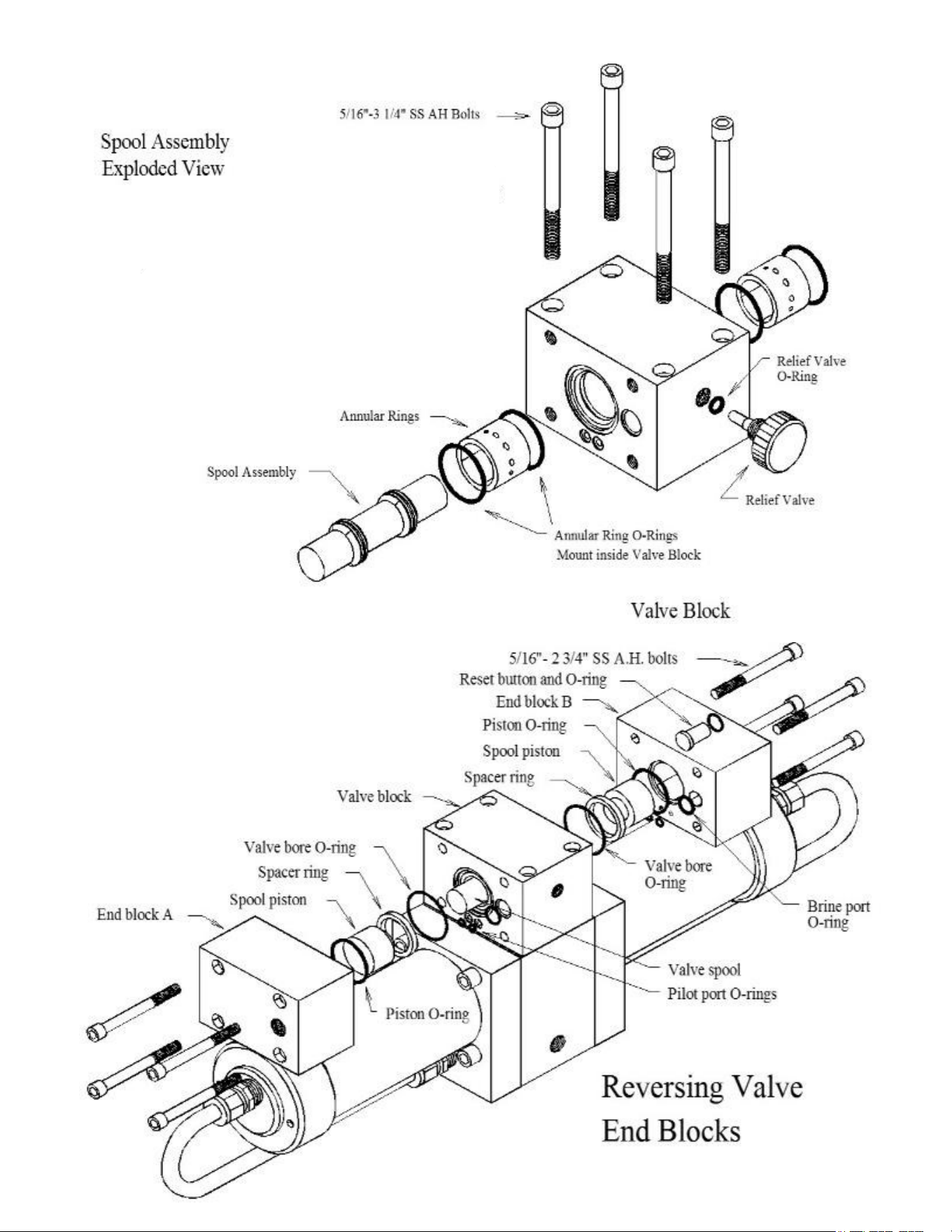
Asymmetrical pressure and flow
readings between pump shifts
Check valve leaking
Failed annular ring
Shaft seal leaking
Contact dealer or see the Clark
Pump repair manual.

28
Poor Product Water Quality
With any product water quality issue, you must ensure accurate calibration if you are
using a salinity meter. For general quality evaluation, your taste is always good
enough.
Membranes are not an exact science and two identical systems can have different
product quality. World health standards deem water of up to 1000 PPM of total
dissolved solids acceptable for drinking consumption. We consider any thing below
750 PPM acceptable but not ideal, and anything below 500 PPM excellent. Factors
that could affect water quality are addressed below.
LOW SYSTEM FLOW OR PRESSURE will equate to lower product quality (higher
PPM). Aquifer systems, which have a higher feed to output pressure ratio (See
nominal pressures under Flow Test), as well as a higher feed flow/membrane
area ratio, will produce water in the 150-200 PPM range.
DAMAGE TO THE MEMBRANE by chlorine contamination. Flushing the system
with chlorinated water will irreparably damage the membrane. Charcoal filters
are used to absorb any chlorine which might be present in flush water. They
must be of proper specification to be suitable. There is no test for chlorine
damage except the process of elimination of other causes.
DIRTY OR SCALED membranes. A dirty (foreign material), scaled (mineral
deposits), or contaminated (bacterial growth) membrane can result in poor
water quality and abnormal operating pressures. If operating pressures are
above normal, then cleaning is indicated. If the system pressures are within
operating normal range, cleaning may have little result. Avoid cleaning as a
diagnostic tool. Low water quality after storage with propylene glycol can usually
be remedied by extended flushing or an SC-2 cleaning.
MECHANICAL LEAKAGE within the membrane pressure vessel. This is an unlikely
but possible cause of poor water quality with old style Codeline pressure
vessels (white). The Spectra pressure vessel has a double O-ring arrangement
that includes a telltale hole between them so that any salt water leaking past an
O-ring will drip into the case and not go into the product water.
If system flow (product plus brine) is 1.5 GPM or above, the membrane is clean, the
product flows are consistent with the system flow and the water quality is still not
acceptable, then replacement of the membrane is indicated.

29
DWYER FLOW METER SERVICE
The mechanical flow meter, can be opened for cleaning if it becomes difficult to read or
if the little ball gets stuck.
The flow meter will come completely apart for cleaning;
1. First remove the meter from the panel (which may require the plumbing fittings to
be removed) by removing the brackets that hold it to the gauge panel.
2. On the very top of the meter is a clear plastic key that slides into place holding the
top cap of the assembly in place. Use a small flat bladed screwdriver to pull the key
out..
3. Hold the meter upright (or the ball will fall out) and then lever the top cap off. It is
hard to see but there is a small notch in the back of the cap where you can put the
small screwdriver and begin to pry the cap off. The cap will move easily so if you to
apply too much pressure you are likely pushing on the wrong place.
4. Invert the flow meter and catch the ball as it falls out.
5. You can use tooth paste or plastic window polish to polish the inside using a small
bottle brush or a Q-tip.
6. Clean the ball and give it a few coats of wax.
7. If the O-rings are damaged or the unit has been leaking, install new O-rings using a
little silicone grease to ease assembly. These are standard O-rings and should be
available at most larger auto parts or bearing stores. Reassemble in reverse.

30
OP-2 BAD SMELLING PRODUCT WATER
The reverse osmosis membrane is permeable by many gases including hydrogen sulfide, the gas
that causes rotten eggs to smell the way they do. If there are bad odors in the feed water they
will go through the membrane and the product water will be affected. Usually the source of the
odor is from the decay of planktonic creatures trapped in the sea strainer and prefilters
. These
tiny oxygen loving creatures soon suffocate and die inside the prefilter housings when the unit is
shut down. Once all the available oxygen is consumed, anaerobic bacteria begin to grow,
causing the odor. If a unit being used frequently begins to make smelly water, usually the
prefilters are the source of the problem. This occurs in a week or two in cold climates, but in less
than one night in very warm waters like the Sea of Cortes or the Red Sea. These bacteria can
spread throughout the watermaker, and begin to grow on the membrane, causing poor water
quality and high feed pressures.
Filling the system with fresh water after every use greatly slows this process, allowing the
automated Spectra units to operate with less frequent prefilter changes, but units operated for
only an hour or so each day will probably need to have the filters changed due to odor before
they are dirty enough to restrict water flow. Prefilters can be cleaned. We recommend that you
have three sets in service: one in the unit, one set soaking overnight in a bucket of clean fresh or
salt water, and one set drying for the next use. After shutting down the unit, remove the used
prefilters and install the dry set. Leave the housings full of air until the next use. On non-
automated systems, open the pressure relief when starting if there is a lot of air in the system
until the air is cleared out through the brine overboard. The filters will get just as clean when
soaked in sea water, but dry much faster if soaked in fresh. Given gentle handling, prefilters can
be reused many times.
Bad smelling product water is usually caused by bad smelling feed water, but can also be caused
by a fouled membrane if the membrane has been left unpickled. If the unit makes smelly but not
salty water after a long idle period and the prefilters are new, the smell can be eliminated by
running the unit unpressurized for an hour or so to flush the membrane.
Odors in the product water can also be eliminated by adding a charcoal filter in the product water
line. Spectra offers a product water filter kit (part no. KIT-FLT-CC).
More on this subject is available on our website at www.spectrawatermakers.com.
8/17/04
31
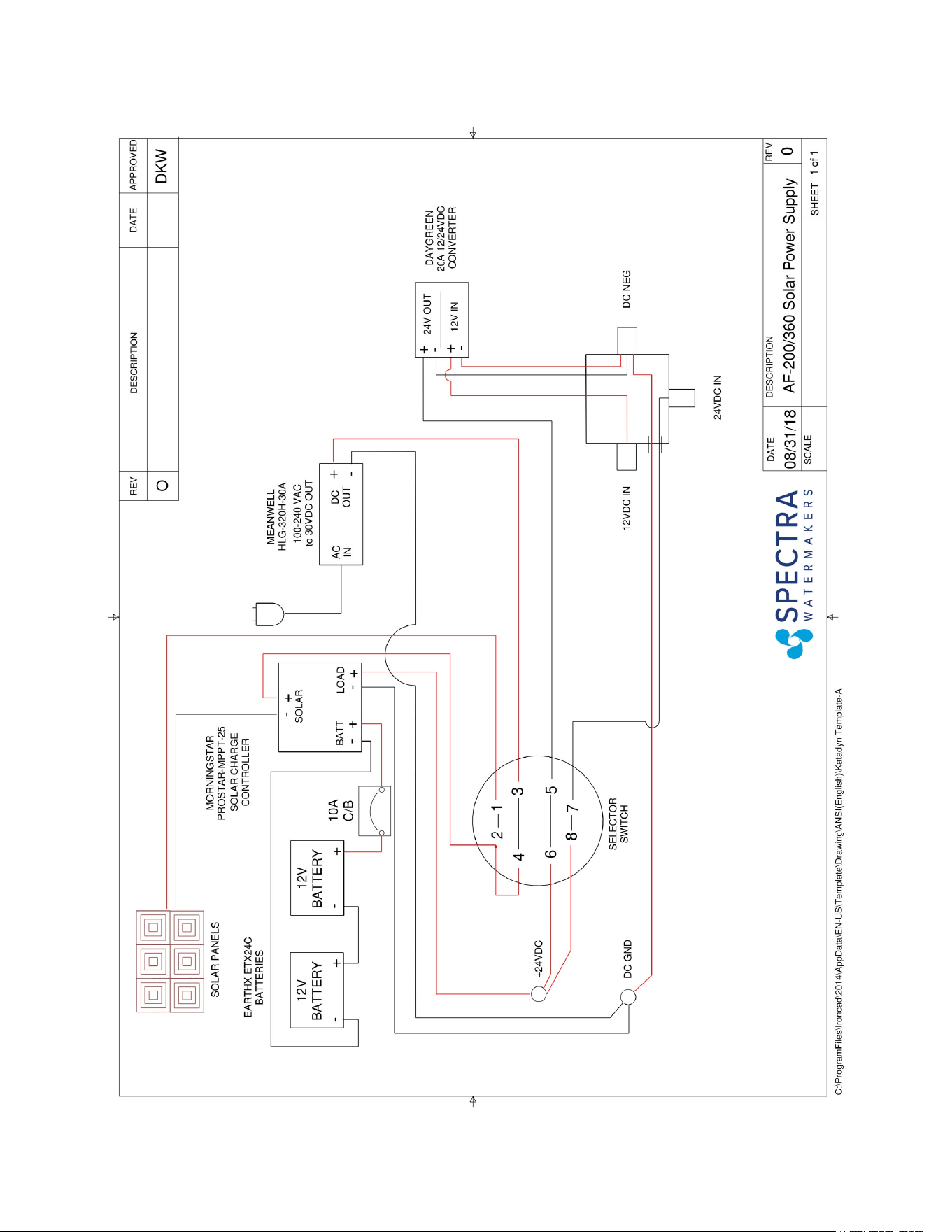
Wiring Diagram
32
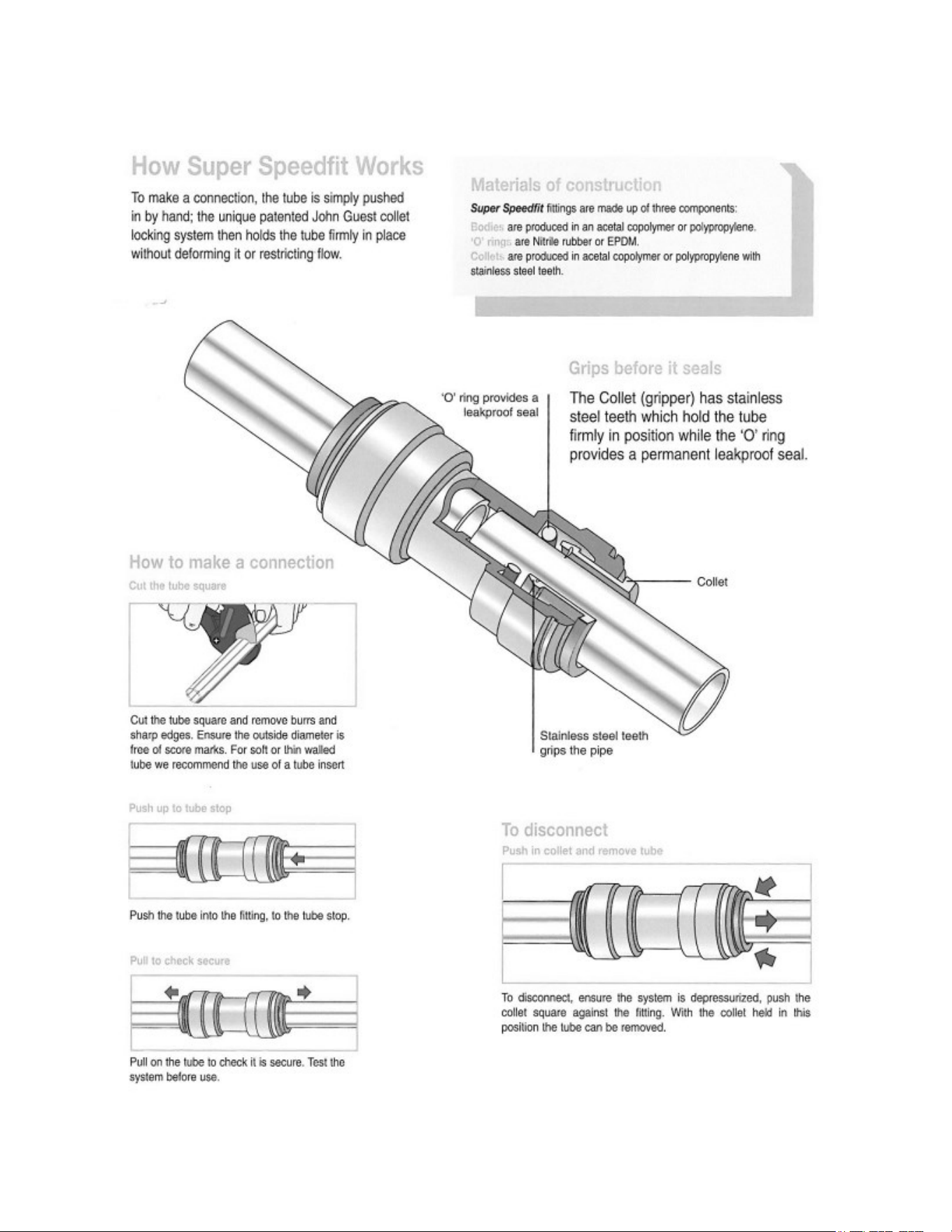
John Guest Super Speedfit Fittings
33
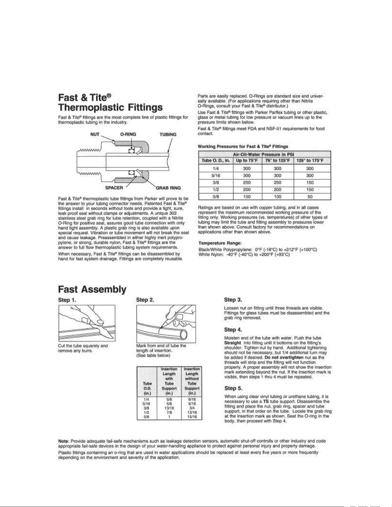
Parker (Black) Tube Fittings
Note; the plastic nut only needs to be finger tight as the fitting uses
an O-ring seal and the nut is only holding the grab rings in place.
Overtightening may strip the threads and render the fitting useless.
34
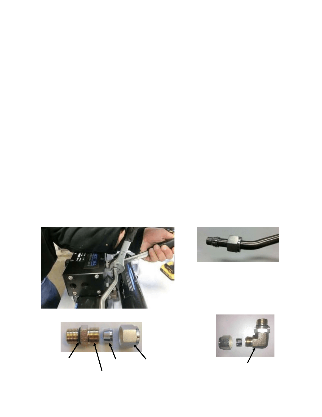
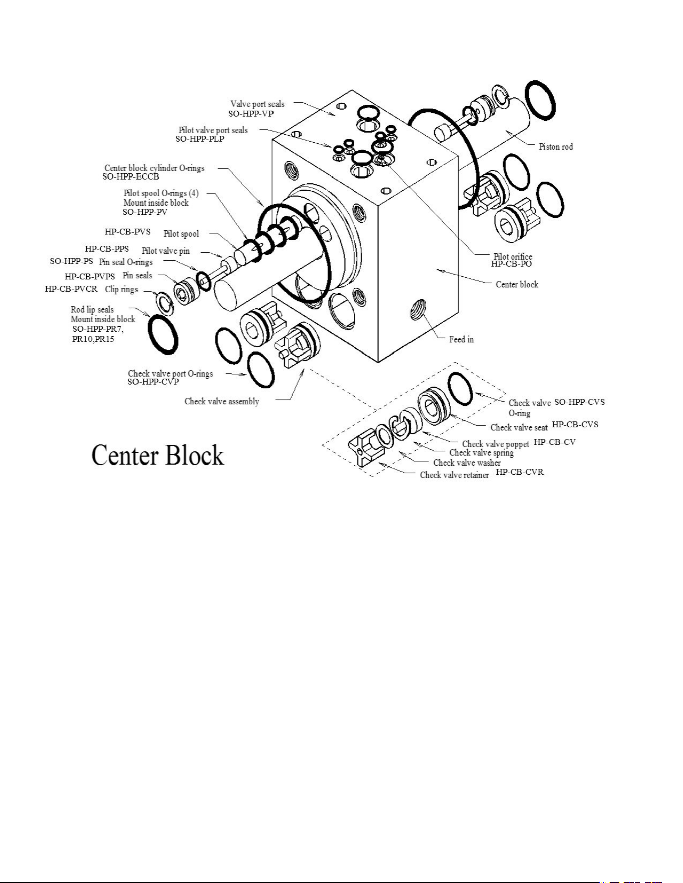
Spectra High Pressure Tube Fitting Assembly Instructions
The Watermaker has eight high-pressure fittings, two on each cylinder on the Clark
Pump, two on the pressure vessel end caps, and two 90-degree elbows on the back of
the Clark Pump. As the compression fitting is tightened, it compresses a ferrule onto
the stainless tubing, fixing the ferrule permanently to the tube and holding the
compression nut captive.
The body of the fitting seals to the underlying component with an O-ring. On the Clark
Pump cylinders and the end caps this O-ring is compressed by tightening the entire
fitting. The O-rings on the 90-degree fittings on the back of the Clark Pump have
captive nuts and washers, which compress the O-rings without turning the entire fitting.
If a tube fitting leaks it can sometimes be resealed by just tightening. You must use
two wrenches, a 13/16-inch wrench to hold the base, and a 7/8-inch wrench to turn the
compression nut. The 13/16-inch wrench will need to be thin so as not to interfere with
the compression nut. If this doesn’t work, disassemble the fitting, grease liberally with
silicone grease (the ferrule and the threads) and re-tighten firmly.
The base O-rings should be gently compressed to achieve a good seal, and may be
damaged by overtightening. As long as the metal washer is in contact with the block,
the O-ring will seal.
Stainless Fitting Hex Nut
Connector O-RING
Nickel-Bronze High Pressure Elbow
Nickel-Bronze High Pressure Straight Fitting
Ferrule
35
Part Numbers
Stainless Fitting Hex Nut
PL-HWR-1/2HN
1/2” Stainless Ferrule
PL-HWR-1/2FR
Connector O-RING
SO-HPP-CT
3/4”-16 Straight
Thread O-RING
Front View
CLARK PUMP
KIT-HP-10
PL-PSG-
DPGMPHPF
Diff. Press.
Gauge Mount
Plate HP Flt
PL-MFF-3/4SX1/2
3/4-16 ST.X
1/2 Flare 37 Degree
ST.BR
FT-PV-20
2.5 X 20 High Pressure Vessel Tube
EL-CT-2x36 HLT
Velcro Hook &
Loop Tie - Blue
EL-CT-2x24HLT
Hook & Loop Ca-
ble Tie-Black
FT-PV-EP2
2.5” Pressure Vessel End Cap
PVC 3/4S Port
PL-HS-1/4VH
"1/4 Clear Vinyl Hose
PL-TEE-3/8PP
3/8"FPT Tee Poly
Propylene
EL-SLT-INLPMNT2
In-Line Salinity monitor
2 Probe
EL-CT-2X18HLT
2" X 18" Velcro Hook &
Loop Tie Blue
PL-HS-5/8VN
5/8" Vinyl Hose
PL-HS-1/2VN
1/2" Vinyl Hose
36
1/8MPT X 1/4 TUBE EL
PL-HBE-1/8X1/4
PRODUCT FLOW METER
PL-FMT-10
PREFILTER HOUSING
FT-FTH-10H
5 MICRON FILTER
CARTRIDGE
FT-FTC-5
1/4FPT X 1/4 TUBE EL
PL-FTE-1/4X1/4P
PRESSURE GUAGE
PL-PSG-2.5L
SUBMERSIBLE WELL PUMP
EL-FP-24VSMDP
Part Numbers
37
HP-TB-VEB-B
HP-TB-VB
HP-TB-VEB-A
HP-TB-BV
HP-CB-CB7
HP-CYL-SST
HP-CYL-R
HP-CYL-EC
HP-CYL-CCA
Not used
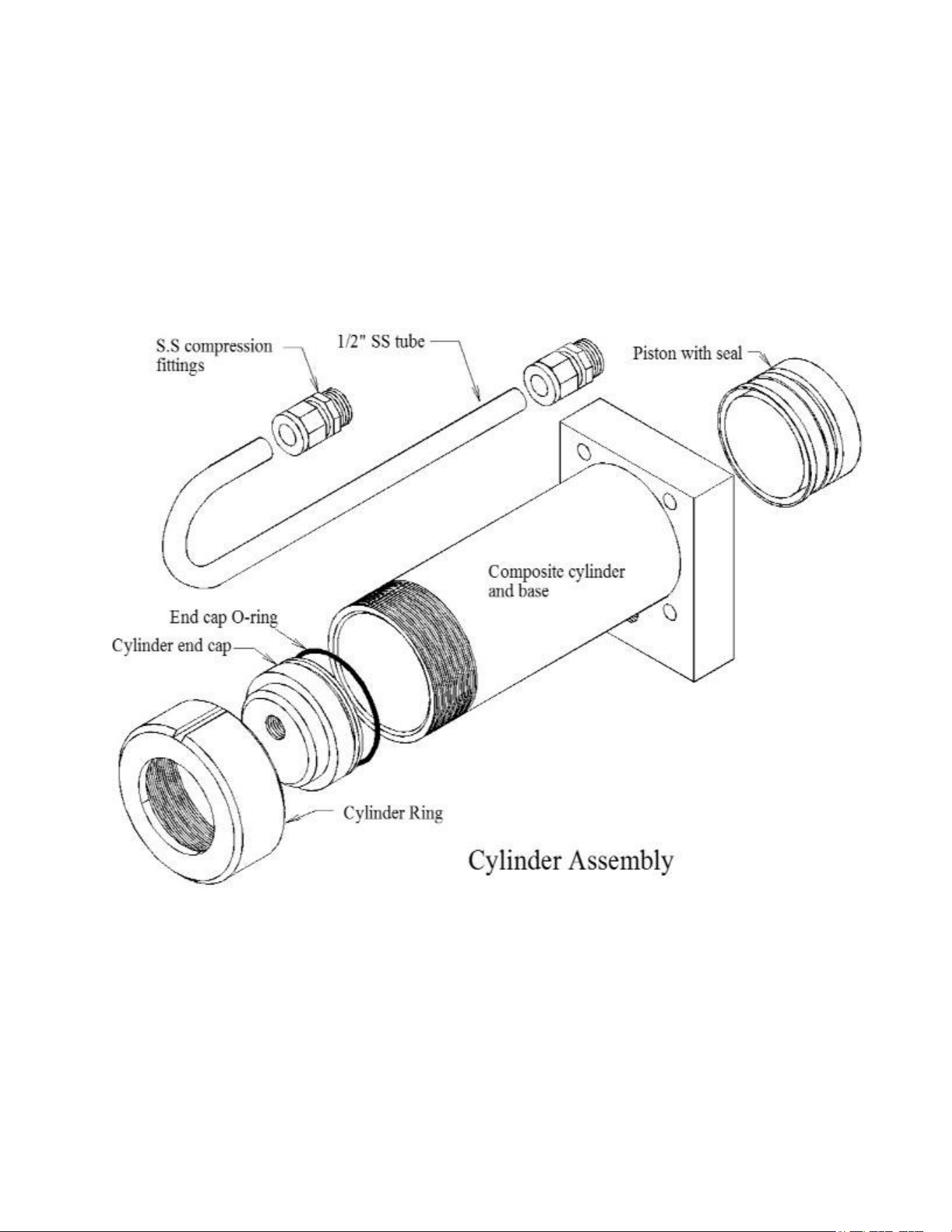
Clark Pump Assembly
38
HD-CPS-5/16X3
KIT-HP-10VSA
HP-TB-ARP
SO-HPP-AR1
SO-HPP-RV
HP-TB-BV
HD-CPS-5/162.75
SO-HPP-SP
HP-TB-VSP
HP-TB-SR
SO-HPP-VB
SO-HPP-PLP
SO-HPP-VP
39
Parts
HP-CYL-3/4R,
40
PL-MTS-3/8X1/2S
HP-CYL-SST
HP-CYL-CCA SO-HPP-ECCB
HP-CYL-EC
HP-CYL-R
HP-CYL-PT
Clark Pump Cylinder Assembly