
1
Katadyn Desalination, LLC
Spectra Watermakers
PH 415.526.2780
FX 415.526.2787
www.spectrawatermakers.com
Revised 10.28.21
Aquifer 200 DC
Operation Manual

2

3
Table of Contents
Installaon
Operaon
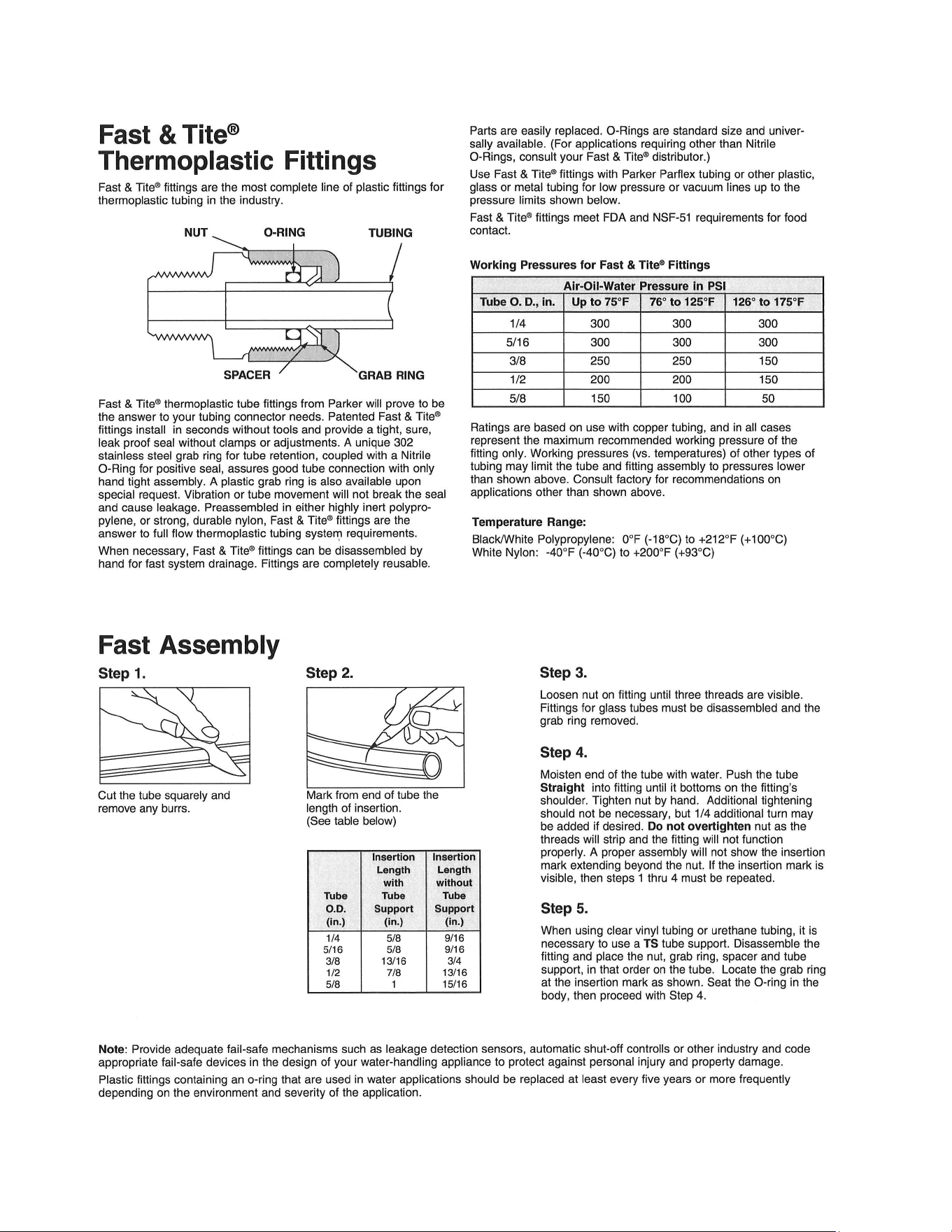
Geng Started .................................................................................................................... 4
Introducon ........................................................................................................................ 5
Feed Water Path ................................................................................................................. 6
Product Water Path ............................................................................................................ 7
Seng Up the Aquifer ........................................................................................................ 8
Electrical .............................................................................................................................. 9
Page Number
New Systems Start Up and Tesng ................................................................................... 10
Normal Operaon ............................................................................................................ 11
Maintenance ..................................................................................................................... 12
Service & Maintenance
Short Term Storage Procedures ........................................................................................ 14
Introducon to Spectra Chemicals……………………………………… ........................ …………...…..15
Long Term Storage ............................................................................................................ 16
Winterizing ........................................................................................................................ 17
Membrane Cleaning .......................................................................................................... 18
Suggested Spares .............................................................................................................. 19
Troubleshoong………………………………………………………………………… ................................. ..20
Poor Water Quality ........................................................................................................... 21
Flow Test ........................................................................................................................... 22
Service Bullens ........................................................................................................... 24-28
Plasc Tube Fing Instrucons……………………………………………………… ........................... ….29
High Pressure Tube Fing Assembly Instrucons………………………… ................... ……………30
Parts breakdown for Aquifer systems ......................................................................... 31-37
4
Unpack the system and inspect it to make sure that it has not been damaged in shipment.
Refer to the shipping list for your system to make sure you have received all of the compo-
nents listed. Do not discard any packaging unl you have found and idened all of the
parts. The small installaon parts are listed on the kit list.
Warning! Spectra Watermakers will not be held responsible for shortages and or freight
damage that are not reported within thirty days of the ship date.
Study the system layout diagram, component photos and descripons before beginning
your installaon. This will assist you in understanding the funcon of each component.
Getting Started
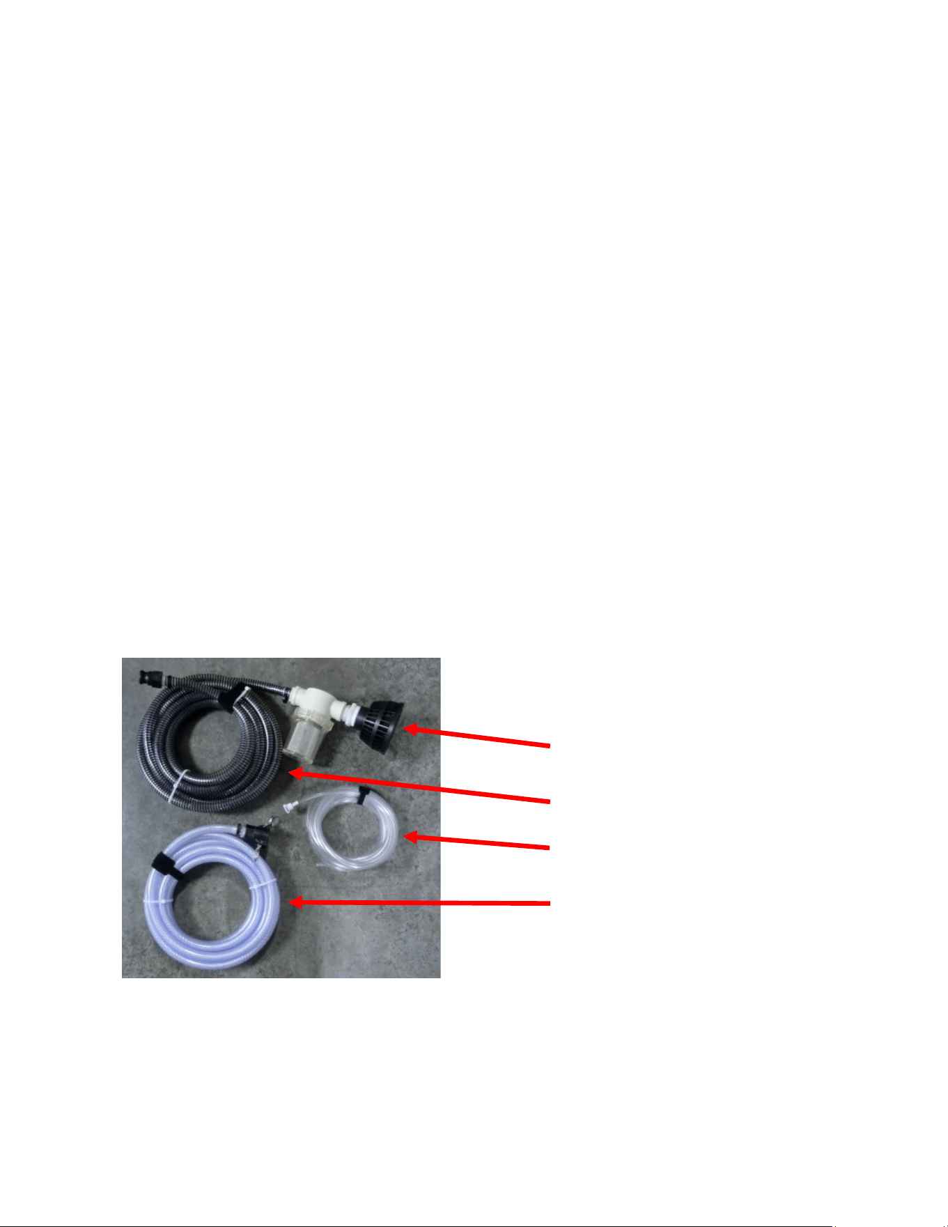
Aquifer Shipping List
• Aquifer Portable Watermaker in Pelican Case
• Hand held Salinity monitor
• Sucon hose (25’) with strainer and Banjo connector
• Brine discharge hose (25’) with Banjo connector
• 1/4 product hose (15’)
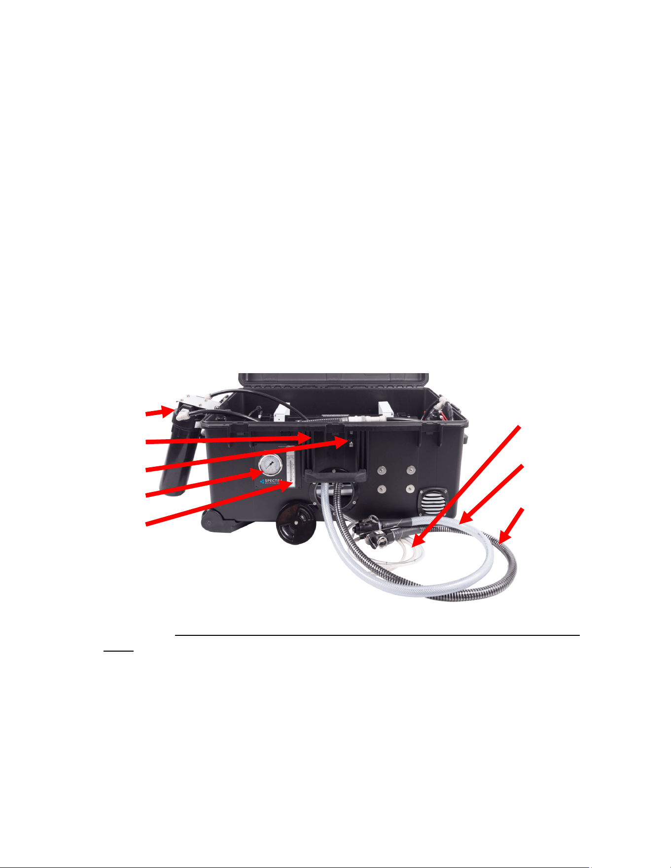
Intake Screen
and Filter
Sucon Hose
Product hose
Brine discharge
hose
5
Originally developed for ocean voyaging yachts, the Spectra Aquifer 200/360 Portable Watermaker is
both a desalinator and a water purier. It is capable of producing high quality, good tasng drinking
water from a variety of water sources including sea water, river water, lake water, or water from a
brackish or contaminated well. It will eecvely separate out salts, organic chemicals, inseccides and
pescides, parasites, cysts, bacteria, and viruses. It does not remove non-ionized heavy metals.
The Aquifer 200 pumps approximately 1.5 gallons (6 liters) of feed water per minute to the reverse
osmosis membrane (the 360 pumps approximately 2.8 gallons (10.6 liters) of feed water per
minute to the membrane). Ten percent of this water passes through the membrane(s) as puried
product water and the remaining water is returned to the feed water source as concentrated brine.
The brine contains whatever was separated from the product water by the membrane and nothing is
retained inside the machine.
Feed water is ltered using a three-stage process. A strainer rst keeps out large debris, and keeps the
sucon hose several inches o the boom, then the water passes through an 80 mesh screen, then a 5
micron pre-lter protects the Clark pump from silt, algae and abrasive parcles before water goes
through the membrane and is separated into pure fresh water and the brine discharge .
The Aquifer 200 and 360 units are congured to run directly from a DC power source (12 or 24 Volt
depending on how it is ordered).
Important: In order to prevent damage to the watermaker, the feed water should never contain
chlorine, bleach, or any other strong oxidizer, which will damage the membrane. Oil in the feed water
will also damage the membrane. The watermaker can be operated using feed water up to about
45,000 ppm TDS sea water.
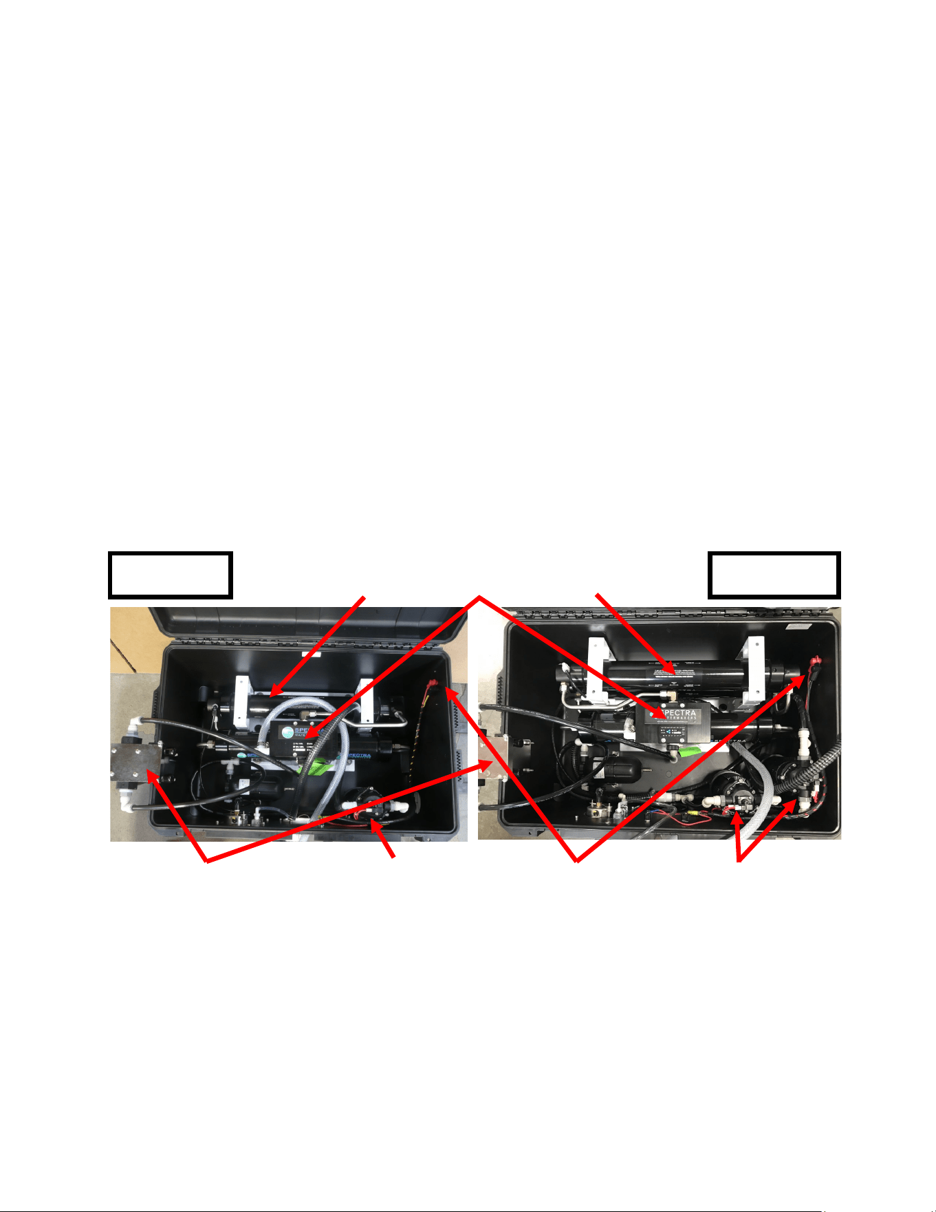
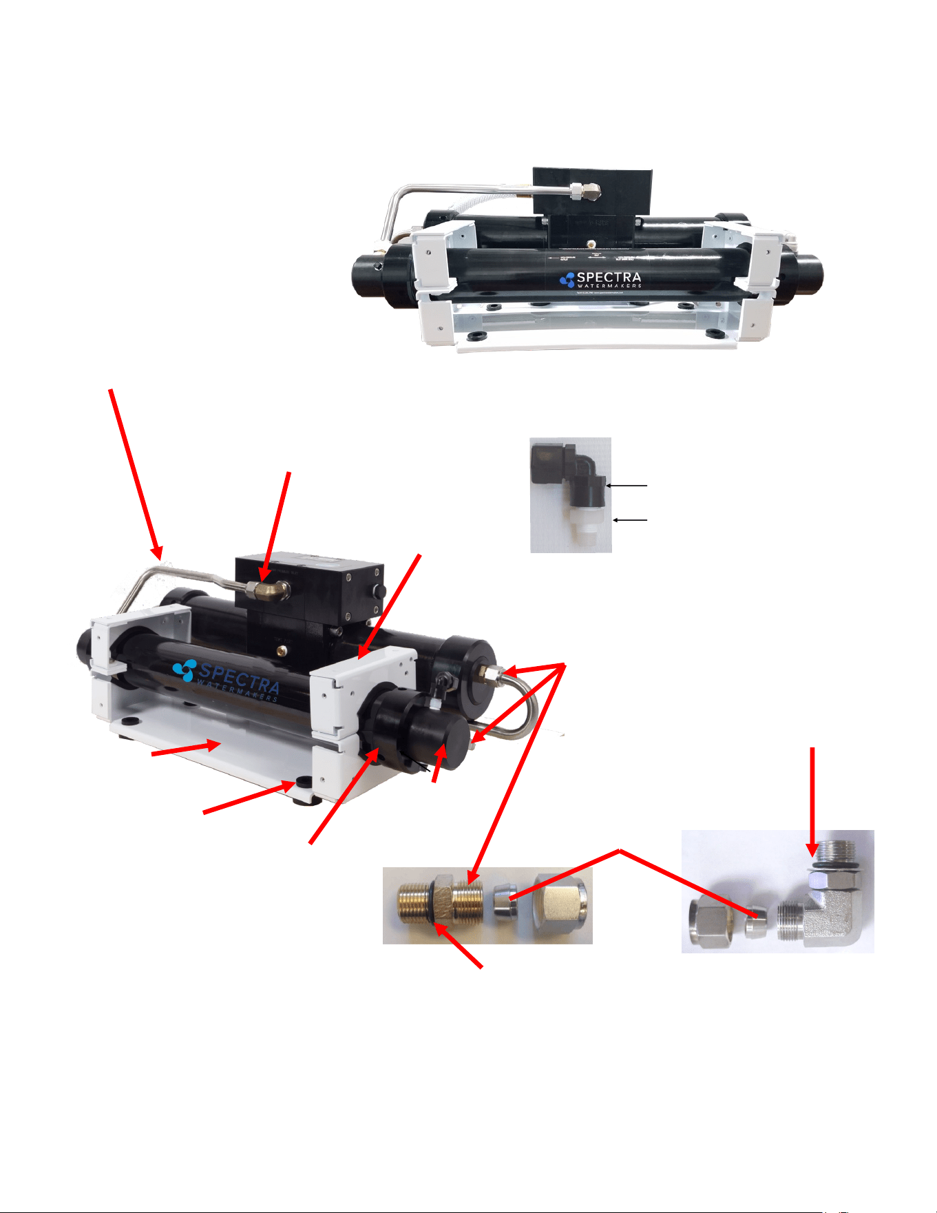
Introduction to the Aquifer 200/360
Fold-out prelter
DC power terminals
Feed Pumps (Two)
Membranes (2) Clark Pump Membrane
Aquifer 200 Aquifer 360
Feed Pump
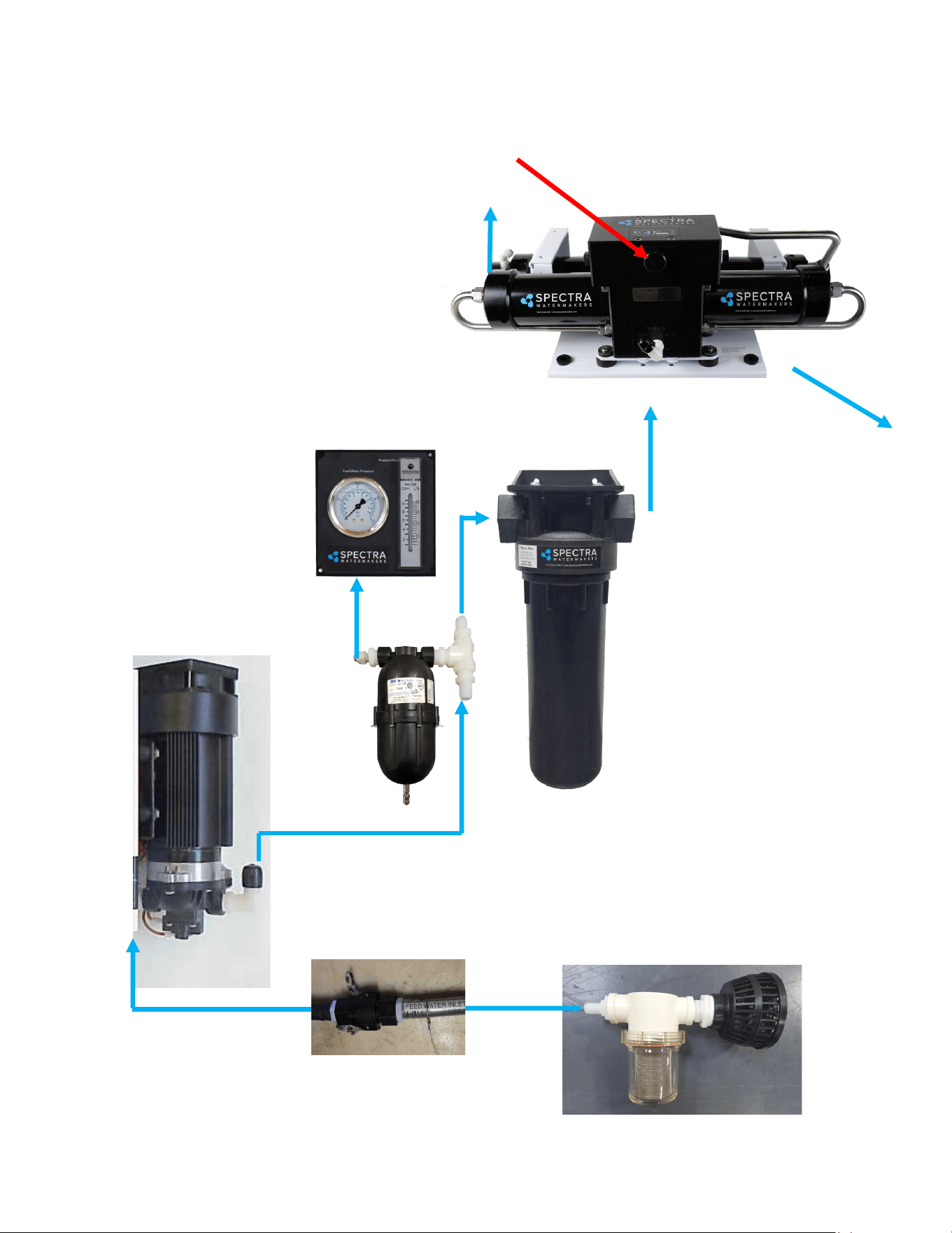
6
Feed Water Strainer and
Screen
5 micron lter and
housing
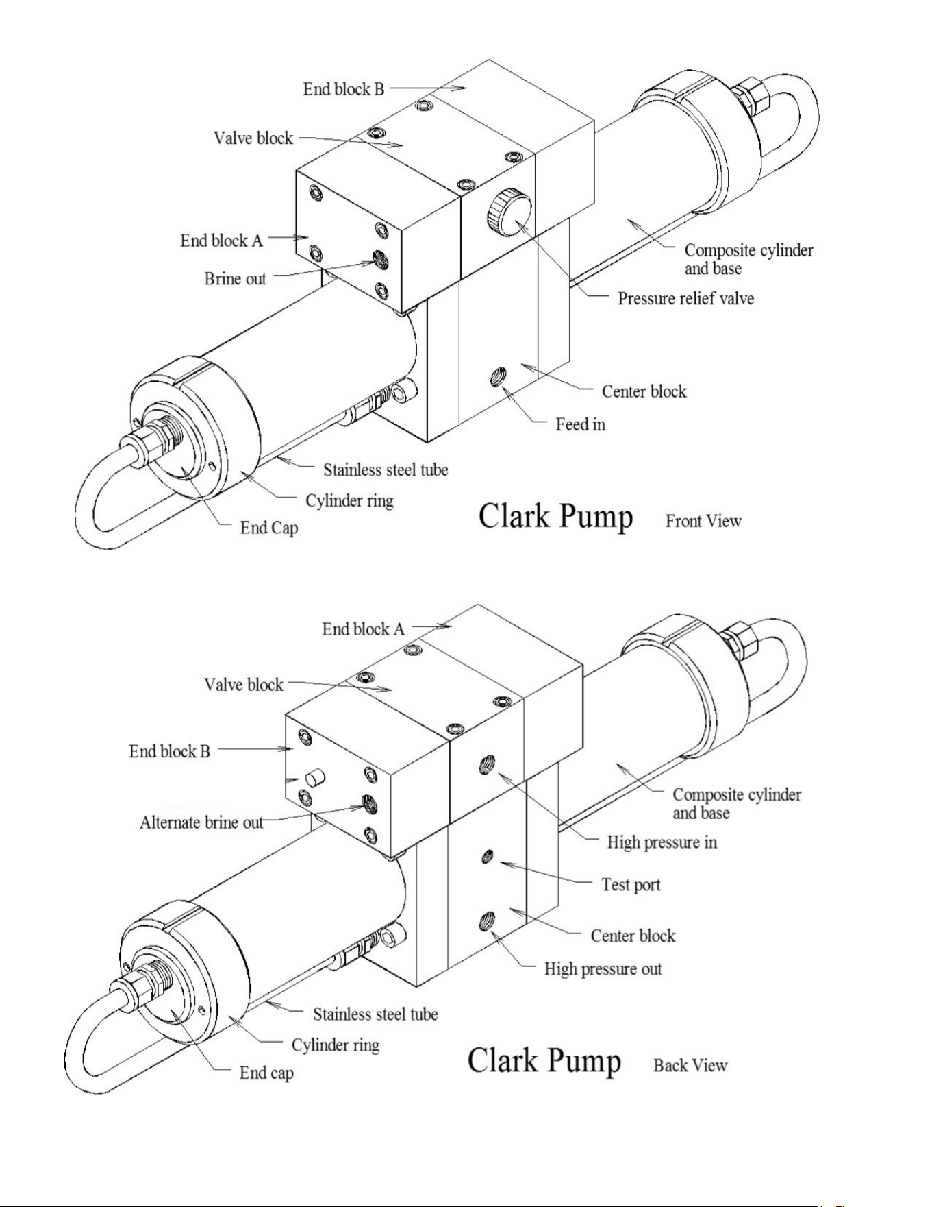
Spectra Clark Pump &
Membrane Assembly
Pressure Relief Valve
Brine Outlet
Aquifer 200 Feed Water Path
Quick Disconnect
Pressure Gauge
Accumulator
Feed Pump
Product Water Outlet
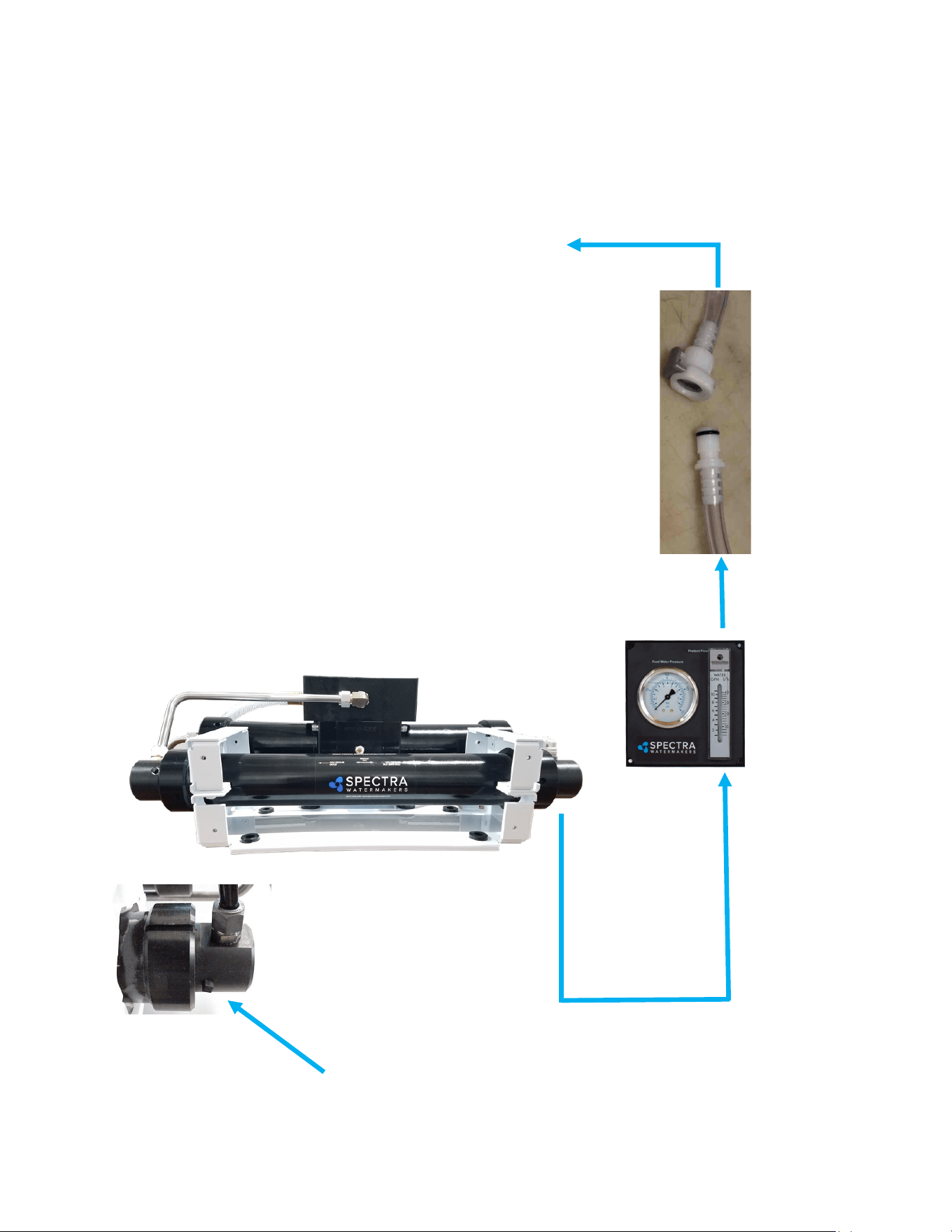
7
Product Water Path
Product Outlet.
Make sure that there is no restricon in the product line.
The hose should be lling vessels or a tank through an air
gap. Do not plumb this hose into the boom of a tank,
allow the water to fall into the top of the tank. Pressure
in the product tubing must never exceed 5psi (0.3bar) at
any me, (running or stopped) or the membrane will be
permanently damaged.
There are four (1/8” NPT)
product water ports (2 in each
end cap)
Clear product water tubing with quick-connect
Product Flow meter
8
SETTING UP THE AQUIFER
CHOOSING A SITE
Your water source should be as free of suspended sand, silt, algae etc., as possible for longer
prelter life. If making water from a bay, lake, or stream choose a locaon as deep as possi-
ble. Avoid areas with surf or chop. The Aquifer Feed Pump is capable of liing the feed water
not more than 10 vercal feet. When seng up the watermaker choose a spot as near the wa-
ter as possible, but do not place the case in the water. It is beer to run a long extension cord
from your power source than to run long hoses to the feed water source. When making water
on a sand beach a small pit can oen be dug in the sand which will ll with clean water. The
water owing into the pit can be used as feed water and the water will be quite clean aer the
system has been running for a short me.
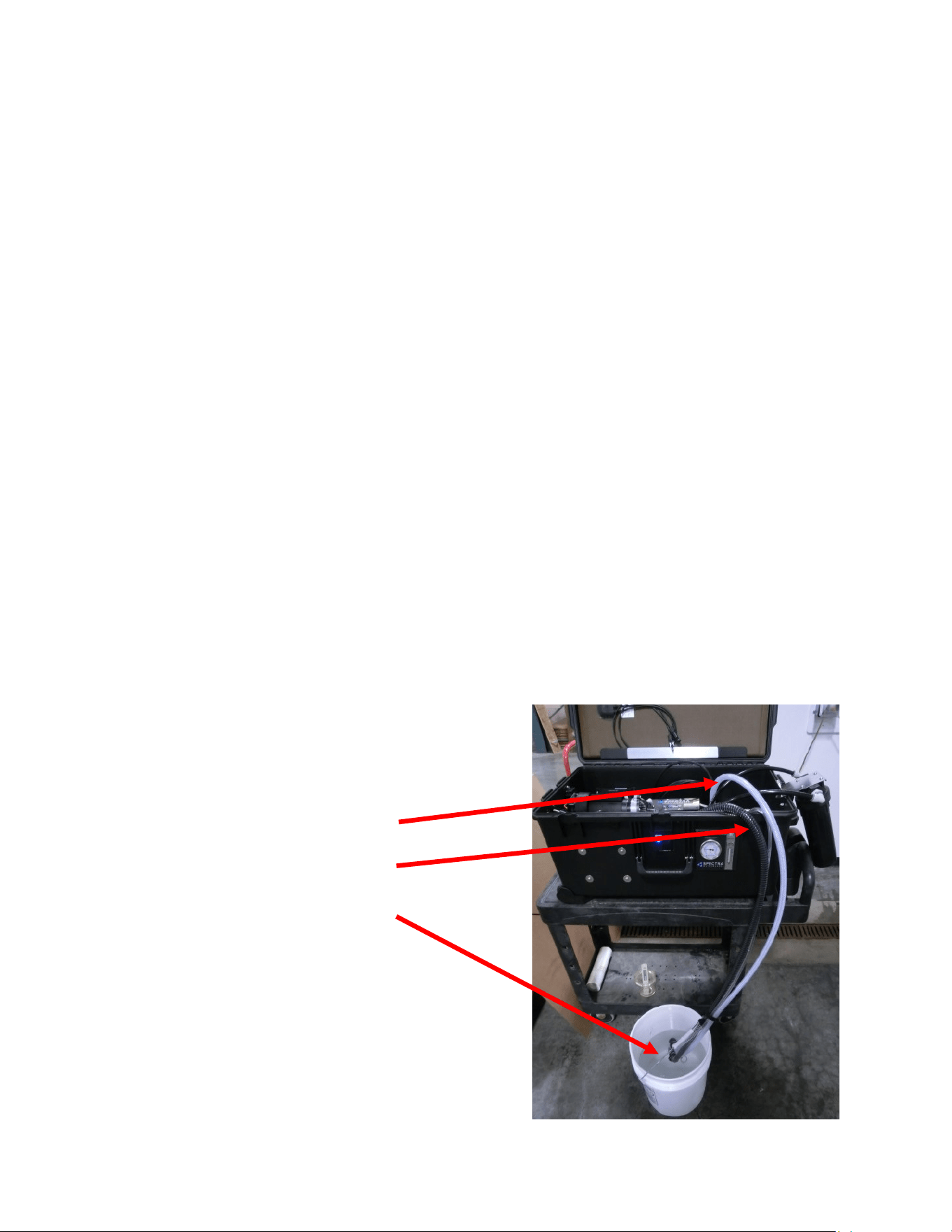
SETTING UP
Note: When connecng the sucon hose Quick Connect ngs be sure they are clean and
free of sand or debris so the seals on the ngs are not damaged! The at end of the male
ng seals against the at rubber seal inside the female ng so both surfaces need to be
clean.
Using the quick connect ngs aach the three hoses: Sucon hose with strainer and lter
basket, brine discharge, and product hose.
You can run the system (as shown below) into a bucket to check operaon. In this case the
stub hoses will be long enough to reach the bucket without aaching the hose extensions.
This is also the process used for cleaning or storage soluon. When fresh water ushing the
system the black spiral sucon hose is used to draw in
the ush water.
Brine Discharge
Sucon Hose
Product Hose
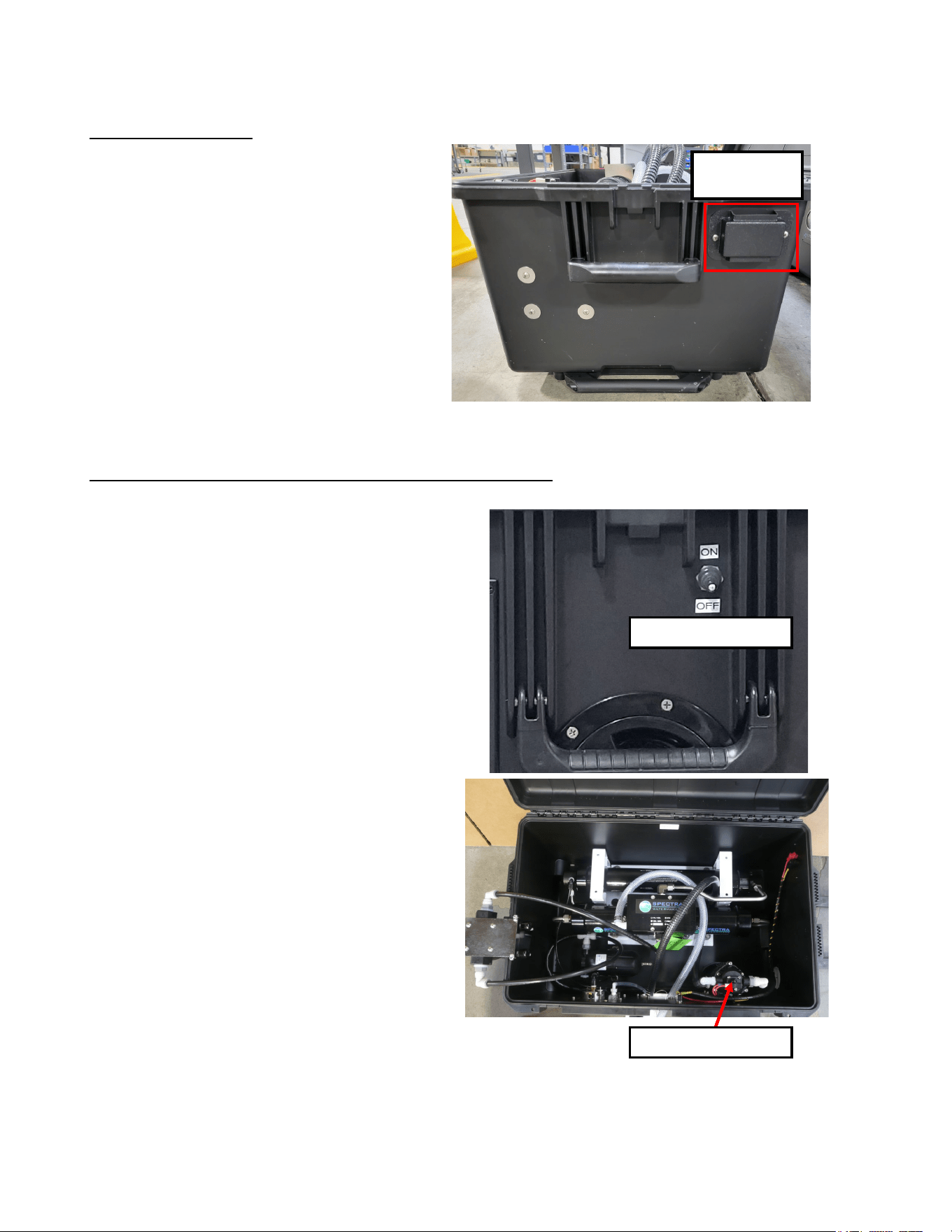
9
Electrical
Aquifer DC Systems
DC powered units will have a terminal block
for connecting directly to your DC power
source. Terminals extend through the case and
power can be connected on either side.
You will need to remove the Terminal Block
cover and connect your external DC power
source and then reattach the cover.
Toggle Switche - Running the Shurflo (Feed Water) Pump
The Shurflo Pump switch must be on for the system
to operate.
Switch on the Shurflo Pump Switch to run the
Aquifer 200. When you have finished running your
watermaker, switch off the Shurflo Pump Switch
and disconnect the Aquifer from the DC power
source.
DC Terminal
Block
(Right Side)
Shurflo Pump Switch
Shurflo Pump Switch
10
Warning! Your watermaker shipped from the factory with a non-toxic potable water system pre-
servave. Damage may occur if this preservave is not ushed out and the membrane is pres-
surized with preservave in it.
DO NOT OPERATE the Aquifer system if the feed water could contain oil.
1. Locate a non-chlorinated water source. If the water has been chlorinated or chemically
treated, replace the 5 micron lter with a Charcoal Filter element .
• Place the strainer end of the Feed Water Hose into the feed water source far enough
below the surface to prevent air from being pulled in. Place the end of the brine hose at
lease 2 meters (6 .) away so that the brine does not mix directly back in with the feed
water.
• Aach the product hose and place the end of it so that any product will drain on the
ground (with the system unpressurized the amount of product during the ush will be
small)
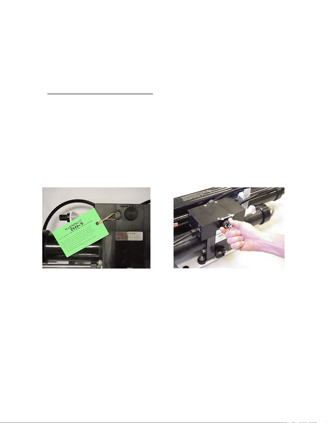
• Ensure that the pressure relief valve is open 1 turn.
• Plug in the DC Power Source.
2. Turn on the pump and check that it is primed by inspecng the brine discharge. About 1.5
gpm (6 lpm) of water should be being discharged with a pulsaon every few seconds.
3. Run the system without pressure for 20 minutes to purge the storage chemicals (4-6 hours
if stored for an extended period with propylene glycol). The system should have an open
ow pressure on the gauge of about 20 PSI (1.2 bar). Water may drip from the product tube.
4. Close the pressure relief valve. The pressure should rise to 60-80 PSI (4.2-5.7 bar) if the
feed water is sea water. If the feed water is brackish or fresh the pressure will be lower. Aer
several minutes, water should begin to ow out of the product water tube.
5. Allow the system to run for 5-10 minutes to purge the product water of preservave, and
then test the product with your handheld salinity tester. When the product is below 750
PPM it is considered potable and may be diverted to the water container for human
consumpon.
Aquifer New System Start-Up and Testing
Open one turn to Purge Preservave Remove Tag and split washer
11
Normal Operaon From a Large Body of Water
If the system has been pickled or stored or contains cleaning compounds, use the “New
System Startup” procedure.
1. Any source of oil-free feed water not saler than sea water may be used. Do not use
water containing large amounts of heavy metals, such as mine tailing runo.
2. Place the intake strainer and screen in the feed water source and the brine discharge hose
at least 2 meters (6.) away from it. Connect the product tube so you are prepared to
collect it (let the rst 5 minutes of product water run onto the ground).
3. Open the pressure relief valve 1 full turn and start the feed pump. When there is good ow
and no bubbles in the brine discharge, close the valve.
4. Aer 5 minutes check the product water with your handheld salinity tester. When it is
below 750 ppm the water is good to drink and you may begin to ll containers.
5. Run the system unl you have lled your container or have made enough to meet your
requirements and 10 liters (3 gallons) for ushing.
6. Make a note of the feed pressure with a clean lter element and change the lter when
the pressure rises more than 5 psi (0.3 bar).
Shung Down
1. You will need 10 liters (3 gallons) of water in a container, which will be used to ush the
watermaker. Use only non-chlorinated water for ushing, product water (freshwater) is
ideal.
2. Place the sucon hose in the ush water (see image on page 8) and start the feed pump.
3. Flush unl the container is empty and then stop the feed pump.
4. Disconnect the hoses and connect the short sucon hose to the brine discharge so water
does not leak into the case. Leave the lid open unl the inside of the case is dry.
The system can sit for up to ve days without further aenon. The system should be ushed
aer every use. You may noce that the system output is higher while is plugged in to AC
power, as the pump will run faster with more power.
Always ensure that the baery is fully charged aer the watermaker is shut down to extend
baery life.
Aquifer Operation
Product (Fresh)
Water Hose
Brine Discharge
Hose
Feed water
suction Hose
Prefilter
Main Power Switch
Pump On/Off
Switch
Pressure Gauge
Product Flow Meter

12
Maintenance
The Seawater Strainer
The sea water strainer’s stainless steel element should be inspected, opened, and cleaned as
needed. Check frequently during operaon.
The Prelter
Service the prelter on a regular basis. The pressure will rise on the pressure gauge when the
lter becomes dirty. Extremely dirty lters will harm system performance and may cause the
feed pump to cycle on the high pressure cut-out switch. Do not leave dirty lters in the ma-
chine during long idle periods, as biological contaminaon will result.
To service the lter, swing it out of the case, open the housing, and discard the old lter. Clean
out the housing bowl, reassemble the housing with a new 5 micron lter element. Leave dry
unl next startup.
Use only Spectra approved lters or you may void your warranty. The lter may be cleaned
several mes by soaking it in water in a bucket. Occasionally, lightly lube the lter housing O-
ring with silicone grease.
General
Periodically inspect the enre system for leakage and chafe on the tubing and hoses. Re-
pair any leaks you nd as soon as praccal. Some crystal formaon around the Clark Pump
blocks is normal. Wipe down any salt encrusted areas with a damp cloth. If any rust ap-
pears at the stainless steel ngs, clean them up promptly. Keep the inside of the case dry
and salt free to protect the electrical components inside.
The Feed Pump and Clark Pump
The feed water pump and the Clark Pump require no roune maintenance except inspecon
for leaks. Tighten any hose clamps or ngs that show signs of leakage. The high pressure
ngs threaded into the Clark Pump have O-ring seals with a straight thread. These should
never leak and should never be over ghtened. If one of the tube nuts starts to leak, it can be
un-threaded, sealed with a bit of silicone grease or silicone seal, and ghtened with two
wrenches very ghtly.

13
The Membranes
The membranes need to be cleaned only when feed pressure begins to rise due to fouling or
the product quality degrades. The primary causes of fouling are biological growth and scaling.
Biological growth occurs when the system is le unused without ushing or pickling. Fouling
from mineral scaling will form when the feed water is “hard” or high in carbonates. Very small
“colloidal metal” and metal oxide parcles can also plug the pores in the membrane. Monitor
the product salinity and feed pressure for higher than normal readings for the exisng condi-
ons. Other condions can cause high pressure such as cold feed water or clogged lters. Low
product ow is usually due to low voltage, damaged feed pump or Clark Pump. Look for all
other causes before cleaning the membrane. Membrane life can be shortened by excessive
cleaning.
There are two types of cleaners: acid and alkaline. The acid cleaner (SC-3) will remove mineral
scaling. The alkaline cleaner (SC-2) is used to remove biological by-products, oil, and dirt par-
cles that get past the prelters. If membrane performance is reduced and it has not been
“pickled” recently, cleaning with both chemicals is recommended. The acid cleaner should be
used rst. Colloidal Metals and Metal Oxides are very dicult to remove. If the membrane
fails to respond to both cleanings, this is an indicaon of another problem with the system, or
that it is me to replace the membrane. Contact Spectra Watermakers before removing a
membrane.

14
Short Term Storage
Fresh Water Flush
The purpose of the fresh water ush is to replace the sea water in the watermaker with fresh
water whenever the system is not operang. The watermaker will last longer and operate
beer if it is always lled with fresh water between uses. If the watermaker is not used for
more than ve days it should be ushed again to ensure that the water inside stays fresh and
oxygenated. In this way, the water maker can be kept ready for immediate use indenitely.
1. You will need 10 liters (3 gallons) of water in a container, which will be used to ush the
watermaker. Use only non-chlorinated water for ushing, product water is ideal.
2. Place the sucon hose in the ush water (see page 9) and start the feed pump.
3. Flush unl the container is empty and then stop the feed pump.
4. Disconnect the hoses and connect the short sucon hose to the brine discharge so water
does not leak into the case. Leave the lid open unl the inside of the case is dry.
If the only fresh water available is chlorinated then a Charcoal (or Carbon) lter is required in
the lter housing. Flushing with chlorinated water will damage the membrane.
Aer ve days, if the watermaker has not been used, re-ush following the above procedure.
Remove the hoses, drain them, and stow them away in the case. Insert the hose connecon
plugs in the hose ngs.

15
Introduction to Spectra Chemicals
We use four types of chemicals: SC-1, SC-2, SC-3, and propylene glycol anfreeze. SC-1 and
propylene glycol are for system storage, while SC-2 and SC-3 are for membrane cleaning.
Note: Never use any chemicals with the system pressurized! Always open the pressure relief
valve 1/2 turn. Always follow the instrucons for purging the chemicals as shown in the New
System Startup secon of your owner’s manual.
Storage: SC-1 prevents biological growth when your system is idle. It should not be used as a
cleaning chemical, nor will it protect your system from freezing. A jar of SC-1 is mixed with 1 to
2 gallons of product or dechlorinated fresh water in a bucket and circulated through the sys-
tem for 10 minutes. This treatment will protect the system for six months, aer which the SC-1
treatment must be repeated. To use SC-1, follow the instrucons for Ventura MPC Storage
Procedure on the following page.
Spectra systems should be stored with propylene glycol if freezing is likely to occur. This is a
food grade anfreeze used to winterize RV’s, boats, and cabins. Propylene glycol also works
very well for prevenng biological growth in warm climates and is good for one year. See Win-
terizing with Anfreeze (OP-1 document on the Spectra website).
Note: Do not use metasodium-bisulfate, Citric Acid, or any other storage chemical not sup-
plied by Spectra. These chemicals, used to store other watermaker brands, are very acidic and
will damage the Clark Pump and void the warranty.
Cleaners: Cleaning can be detrimental to the membrane and shorten its life. Avoid unneces-
sary cleaning, and avoid cleaning as a diagnosc tool.
SC-2 is an alkaline cleaner used to remove light oil, grime and biological growth. It is most
eecve if heated to 120 deg. F, which is dicult on a boat. In most cases the water quality
will increase in PPM (salinity) aer an SC-2 cleaning. Aer a few hours it should recover to
near the level it produced before the cleaning.
SC-3 is an acid cleaner used to remove mineral and scale deposits. In most cases this is used
rst and if there is no improvement, go on to the SC-2. SC-3 will in most cases lower the prod-
uct PPM and overall pressures. Scaling is a slow process that may take several months or
years. SC-3 is less harmful to the membrane and will almost always improve the performance
of an older membrane.
For cleaning with either SC-2 or SC-3, see the Cleaning Procedure.
16
Long Term Storage Procedures
Watermakers are best run connuously. When not in use, biological growth in the membrane
is the leading cause of membrane fouling. A warm environment will cause more growth than a
cold environment. If the system is to be le unused for more than ve days, perform the fol-
lowing storage procedure. The procedure introduces a chemical compound into the system
that prevents biological growth. This procedure requires de-chlorinated water. Spectra SC-1 a
special storage compound, formulated to be compable with the modern engineering plascs
and composites in the Spectra pumps. Do not use any substute except propylene glycol
(with no Ethyl Alcohol). If you wish to use glycol for storage, follow the winterizing instrucons
on the container. SC-1 storage compound must be mixed at a rao of 1 packet to 3 gallons
(12L) of fresh water to have the proper soluon for up to six months storage.
Cauon! Avoid contact with skin, eyes, or lungs with the storage chemical.
Aquifer Storage Procedure
The watermaker can be stored for periods up to six months using this procedure.
1. Make or buy 4 gallons of chlorine-free water and put it in a bucket.
2. Place the end of the feed hose in the bucket and the brine hose to drain.
3. Start and run the feed pump unl you have one gallon of fresh water le in the bucket.
4. Mix 1 packet of SC-1 storage compound with the water in the bucket and place the end of
the brine service hose in the bucket.
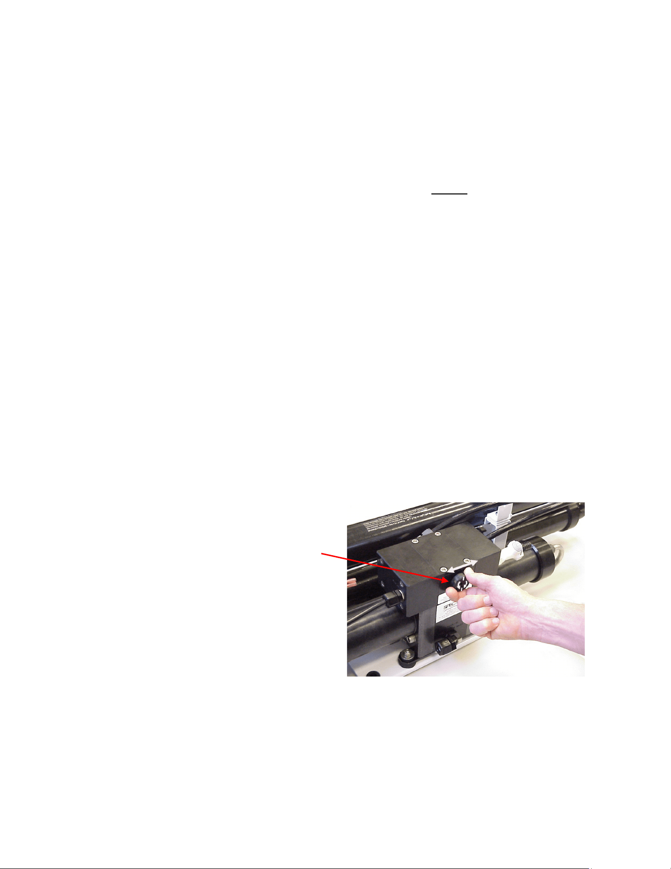
5. Make sure the pressure relief valve on the
Clark Pump is OPEN (unpressurized)
by turning
1
/
2
turn counterclockwise
6. Turn on the feed pump. Circulate the storage
chemical in the system for approximately 10
minutes. Turn o the feed pump when n-
ished.
Clean Up
• Remove the 5 micron lter element from its housing and put in a dry one.
• Rinse and dry the inside of the case, being careful not to get water inside the pump motor.
• Charge the baery.
• Remove the hoses, drain them, and stow them away in the case. Insert the hose connec-
on plugs in the hose ngs.
17
Storage and Winterizing with Antifreeze
The watermaker can be stored for up to one year in any climate using this procedure.
1. Put 3 gallons of chlorine-free fresh water into a bucket. Perform a fresh water ush as de-
scribed in the normal operaon secon. Run the feed pump unl the bucket is empty.
2. Pour 2 gallons of low temperature propylene glycol (with no Ethyl Alcohol) potable water
system anfreeze into the bucket.
3. Make sure the pressure relief valve on
the Clark Pump is OPEN (unpressurized)
by turning it
1
/
2
turn counterclockwise.
4. Start and run the feed pump unl an-
freeze begins to come out of the brine dis-
charge hose.
5. Stop the feed pump. Direct the brine out
put into the bucket.
6. Start the Feed pump and circulate the re-
maining anfreeze for a few minutes unl
well mixed.
7. Stop the feed pump and discard any an-
freeze remaining in the bucket.
8. Blow out or drain the product tubing, as it will not contain anfreeze.
9. Leave the pressure relief valve open.
Clean Up
• Remove the prelter from its housing and replace with a clean dry lter element.
• Rinse and dry the inside of the Aquifer case to prevent corrosion. Do not get the Feed pump
motor wet.
• Remove and drain the service hoses and stow them away in the case. Insert the hose con-
necon plugs in the hose ngs.
• Charge or remove the baery for storage.
Recommissioning
Propylene glycol can be dicult to ush from a membrane, especially aer extended storage
periods. This results in high salinity water (high PPM) and residual avor in the product water.
We recommend ushing the system WITH THE PRESSURE RELIEF VALVE OPEN for 4-6 hours
aer storage with propylene glycol—the longer the beer. If, aer extended ushing, you sll
experience low product water quality, cleaning with SC-2 usually removes all traces of propylene
glycol and returns the salinity to the level it was before storage with propylene glycol. See the
Cleaning Procedure on page 20.

18
Membrane Cleaning
Membrane Cleaning
For normal cleaning, the SC-3 Acid Cleaning Compound is used rst, then the SC-2 Alkaline
Cleaning Compound. If known bio-fouling is present, the SC-2 may be used rst. Using hot
water if possible, up to 120° (45C) is recommended, as it greatly enhances the ability of the
cleaners to do their jobs.
If the history of the system is unknown or it has been le “unpickled” for an extended length
of me and biological growth is present, it is recommended that the system is cleaned with
SC-2, using unchlorinated fresh water before the system is run under pressure. If the housing
is full of smelly discolored water, the system was not properly stored. Install a clean lter.
Check the membrane by running the system for a few minutes in a bucket (see pg.8) and
then examine the brine water: if it’s discolored and smells bad, perform an SC-2 cleaning. If
the brine is fairly clean, the system can be purged, run normally, and checked for perfor-
mance. Clean the membranes only if indicated.
Heang the water is preferable. One way to do this is to nd a camp stove and use a large
stainless steel pot to heat the soluon in. The cleaning soluon throughout the system will
heat as it circulates in and out of the pot. An alternave is to heat the one or two gallons of
inial water to 120° on a stove before mixing in the cleaner and circulang it into the system.
Periodically stop and reheat the soluon.
Spectra cleaning compound (SC-2 or SC-3) must be mixed with fresh water at a rao of 1
container of compound to 3 gallons (12L) of unchlorinated water. When this concentrate is
circulated through the system the chemicals will mix with the water in the system and get
to the correct rao of 8 oz. (250g packet) to 5 gallons (20 liters) of water.
The cleaning procedures are the same for the SC-2 and SC-3 cleaners;
1. Flush the system as shown in the Normal Operaon Secon and make cleaning soluon
as above.
2. Place the inlet service hose, brine discharge service hose, and product hose in the bucket.
3. Make sure that the pressure relief valve is OPEN (un-pressurized).
4. Mix the cleaning chemical in the bucket.
5. Start the system and circulate the chemical through the system for 20 minutes.
6. Allow the system to soak for an hour; or overnight if the chemicals are cold.
7. Run the pump for another 20 minutes.
8. Stop the pump, move the brine discharge hose to a drain and start the pump unl the
bucket is empty.
9. Flush the system using the instrucons for “New System Startup.”

19
Suggested Spares
Short term use, weekends etc.
We suggest a basic cruise kit A. This kit consists of six 5 micron lters, and 2 SC-1 storage
chemicals.
Use for 2 to 6 months at a me.
Two basic cruise kits, one replacement feed pump head.
Longer than 6 months
Addional lters, Oshore Cruising Kit consisng of Clark Pump seals, O-rings, tools and
membrane cleaning chemicals. One replacement strainer.
Spectra Watermakers parts list:
SC-1 STORAGE CHEMICAL KIT-CHEM-SC1
SC-2 CLEANER KIT-CHEM-SC2
SC-3 CLEANER KIT-CHEM-SC3
BASIC CRUISE A KIT-BCK-A
5 MIC FILTER FT-FTC-5
CHARCOAL FILTER FT-FTC-CC
FEED PUMP HEAD PL-PMP-SFPH
FILTER HOUSING O-RING SO-FHS-10H
OFF SHORE KIT KIT-OFFSH
20” MEMBRANE FT-MB-20
SUCTION STRAINER KIT-AQ-ATNASSEM
Part Number

20
Troubleshooting
Symptom Cause Remedy
Feed pump runs but no pressure
No lights on the switches
Pump will not run
Feed pump air locked
Pressure relief valve open
Baery fuse blown
Baery dead
Main Power switch o
Pump Fuse blown
Open pressure relief valve, run unl
there are no bubbles in the line and
then close valve
Close valve
Replace fuse
Be sure baery is charged before
storage
Be sure lights are o on switches
when storing
Main Power switch on
Replace Fuse
Feed pump starts but shuts down
on high pressure
Prelter clogged
Closed valve or blockage in ow
Change lter
Check ow path for closed valve or
kink in hose
Low water producon
High feed pressure
Strainer or prelter clogged Service prelter and strainer
Low water producon,
Low pressure
Pressure relief valve parally open
Worn pump head
Close valve
Check ow, should be 1.4 GPM
Close o discharge hose and pres-
sure should build to 120psi, if not
the pump head needs to be re-
placed
Water producon normal, but
high feed pressure and/or high
amperage
Cold seawater temperature
Fouled membrane
Normal condion
Clean membrane
Water producon normal, but
lower pressure, and lower amper-
age
Warm sea water or brackish water. Normal condion
Asymmetrical pressure and ow
readings between pump shis
Check valve leaking
Failed annular ring
Sha seal leaking
Contact dealer or see the Clark
Pump repair manual.

21
Poor Product Water Quality
With any product water quality issue, you must ensure accurate calibraon if you are using a
salinity meter. For general quality evaluaon, your taste is always good enough.
Membranes are not an exact science and two idencal systems can have dierent product
quality. World health standards deem water of up to 1000 PPM of total dissolved solids
acceptable for drinking consumpon. We consider any thing below 750 PPM acceptable but
not ideal, and anything below 500 PPM excellent. Factors that could aect water quality are
addressed below.
LOW SYSTEM FLOW OR PRESSURE will equate to lower product quality (higher PPM).
Aquifer systems, which have a higher feed to output pressure rao (See nominal
pressures under Flow Test), as well as a higher feed ow/membrane area rao, will
produce water in the 150-200 PPM range.
DAMAGE TO THE MEMBRANE by chlorine contaminaon. Flushing the system with
chlorinated water will irreparably damage the membrane. Charcoal lters are used to
absorb any chlorine which might be present in ush water. They must be of proper
specicaon to be suitable. There is no test for chlorine damage except the process
of eliminaon of other causes.
DIRTY OR SCALED membranes. A dirty (foreign material), scaled (mineral deposits), or
contaminated (bacterial growth) membrane can result in poor water quality and
abnormal operang pressures. If operang pressures are above normal, then cleaning
is indicated. If the system pressures are within operang normal range, cleaning may
have lile result. Avoid cleaning as a diagnosc tool. Low water quality aer storage
with propylene glycol can usually be remedied by extended ushing or an SC-2
cleaning.
MECHANICAL LEAKAGE within the membrane pressure vessel. This is an unlikely but
possible cause of poor water quality with old style Codeline pressure vessels (white).
The Spectra pressure vessel has a double O-ring arrangement that includes a telltale
hole between them so that any salt water leaking past an O-ring will drip into the
case and not go into the product water.
If system ow (product plus brine) is 1.5 GPM or above, the membrane is clean, the product
ows are consistent with the system ow and the water quality is sll not acceptable, then
replacement of the membrane is indicated.

22
Aquifer Flow Test
The ow test is the most useful diagnosc test for system performance, and should be done
before replacing or cleaning your membrane. Changes in producon or water quality are
normally caused by something other than the membrane, unless the system has been le
unused for a long me.
Before the ow test, change the lter and clean the sea strainer. Carefully check for water or
air leaks, as air in the system will cause low producon and errac salinity. Look for air bubbles
in the product ow meter, feed water hoses, and brine overboard hose.
Run the system and watch the pressures very closely. If the feed pressure to the Clark Pump is
asymmetrical from one stroke to another, this could be part of the problem. A dierence of a
few PSI is acceptable, but anything over that is an issue. If the pump is asymmetrical, Clark
Pump repairs should be done before connuing with these tests.
If no asymmetry is noted, connue with this test.
Make sure the ShurFlo overpressure cutout switch (PL-PMP-SFPH) is set to 125 PSI. With the
pump running, close the brine service valve. The feed pressure should rise to 125 PSI, then the
pump should shut o. If the pump shuts o at a lower pressure see “SF-2 Adjust ShurFlo
Pressure Switch,” later in this manual.
You will need a graduated bucket and a stopwatch. Measurements must be very accurate, as
errors of just a few percent will skew the results. Log the voltage at the feed pump at the same
me. Conrm at least 12.5 volts at the pump on 12-volt systems.
1. First divert the product ow into the bucket and record how long it takes to accumulate a
given amount. Product ow is usually expressed in Gallons Per Hour or Liters Per Hour, so
it’s easiest and most accurate to collect the ow for exactly ten minutes, then mulply the
quanty by six to get GPH or LPH. Alternavely, you can collect exactly one gallon or four
liters then calculate GPH or LPH as follows:
3600/me in seconds x quanty of water=GPH or LPH
There are 3600 seconds in an hour.
Example: It took 9 minutes, 45 seconds to collect 1 gallon of product water, so
3600/585 x 1 = 6.15 GPM (9 mes 60 seconds is 540 plus 45 equals 585 seconds).

23
2. Divert the brine discharge, and the product water, both into the bucket. Feed ow (brine
discharge and product combined) is usually expressed in Gallons Per Minute or Liters Per
Minute. For the simplest and most accurate measurement, divert exactly 5 gallons or 20
liters, record the me, and calculate GPM or LPM as follows:
60/me in seconds x quanty of water = GPM or LPM
Example: It took 3 minutes (180 seconds) to collect 5 gallons of feed ow, so
60/180 x 5 = 1.67 GPM
*pressure relief valve open ½ turn
In order to make good water, you need the proper amount of feed water ow, as in the table
above. Compare the product ow to the total feed ow. Product ow should be 7% of total ow
for an Aquirer 200, and 9.5% of total ow for an Aquifer 200. If product percentage is low, you
may have an internal leak in the Clark Pump.
For every
1
/
10
th
of a GPM feed water ow loss, we will lose about
1
/
2
gallon per hour of product
ow and the salinity will go up 100 PPM.
Low feed ow combined with low system pressures is most frequently due to a worn ShurFlo
pump head (PL-PMP-SFPH).
5/23/14
System
Feed Static * Feed Flow Product Flow
Pres-
sure
Pres-
sure Flow MIN MIN Flow Flow MIN MIN
psi bar psi gpm lpm gpm lpm gph lph gph lph
Aquifer
150 60-70 4.2-5 10-15 1.7 6.4 1.65 6.2 6.5 24.6 5.7 21.5
Aquifer
200 80-90
5.6-
6.3 20-25 1.7 6.4 1.6 6.0 8.3 31.4 7.7 29.1

24
The following pages include Spectra’s most commonly used technical bullens, covering tests,
adjustments, troubleshoong, and common points of confusion.
MISC-1: DWYER FLOW METER SERVICE
The mechanical ow meter, PL-FMT-10 (10 GPH range) or PL-FMT-20 (20 GPH range) can be
opened for cleaning if it becomes dicult to read or if the lile ball gets stuck.
The ow meter will come completely apart for cleaning. First remove the meter from the
panel. Remove the four small screws that hold the stainless steel bracket in place. Carefully
pry o the bracket. On the very top of the meter is a clear plasc slide-o cover over an Allen
screw. Use a at bladed screwdriver to push the cover o. Holding the meter upright, remove
the Allen screw with a ¼” Allen wrench. Invert the ow meter and catch the ball as it falls out.
You can use tooth paste or plasc window polish to polish the inside using a small bole
brush. Clean the ball and give it a few coats of wax. If the o-rings are damaged or the unit has
been leaking, install new o-rings using a lile silicone grease to ease assembly. These are
standard o-rings and should be available at most larger auto parts or bearing stores.
Reassemble in reverse.
MISC-3 ACCUMULATOR PRESSURE
Your Spectra Watermakers is supplied with a pressure accumulator tank (PL-ACC-TK), which
should be installed in the feed water line between the prelters and the Clark Pump.
The purpose of the feed line accumulator is to reduce the spikes in the feed pressure caused
by the cycling of the Clark Pump. If the accumulator is not properly charged it can lead to
problems with the ShurFlo Pump pressure cutout switches. The accumulators have an air
valve on top similar to those found on car res. This allows the internal air bladder of the
accumulator to be pre-charged. The accumulator should be pumped up to about 65 psi (4.5
bar) for best results. Add air using a re pump or air compressor. You can experiment with the
exact pressure that will give the best pulsaon dampening on your installaon.
Technical Bullens

25
PF-3 PREFILTERS– ShurFlo
An Aquifer system uses a single 5 micron lter to clean the feed water of abrasive materials
while the system is in operaon. A carbon lter may be used to prevent the entrance of
chlorine during fresh water ushing.
During normal operaon, the feed water is ltered in two stages. First it passes through a ne
mesh metal sea strainer, which protects the Feed Pump from foreign materials and larger sea
creatures. Aer passing through the Feed Pump, the feed water passes the lter housing
containing 5 micron element, removing very ne parcles that could damage the Clark Pump
and shorten membrane life.
Cleaning schedules will vary widely depending on how and where the system is used. If large
amounts of feed water are run through the system over a relavely short period of me in
biologically ferle near-shore waters, the prelters will plug up, water producon and quality
will drop, and the system pressure will change dramacally. If the pressure gauge was installed
before the prelters, as pictured in this manual, the pressure will increase. If the pressure
gauge was installed aer the prelters the pressure will drop
When operated for only an hour or two a day in inland or near-shore waters, the trapped
plankton will begin to decay in the lters long before the elements plug up. The decaying
plankton and bacteria will cause a “roen egg” smell in the product water. This decay will set
in overnight in tropical waters, or aer a week or two in higher latudes. If handled gently and
changed regularly before they get too smelly, lters can be cleaned several mes.
In crystal clear blue water condions, the lters may need to be cleaned much less frequently.
If a charcoal lter is used for fresh water ushing the system it will not plug up unless you have
some incredibly dirty domesc water in your supply tank. About six months aer installaon
the charcoal lter element will lose its eecveness and must be replaced. This is purely a
funcon of me.

26
PF-2: CHARCOAL FILTERS
The charcoal lter element (FT-FTC-CC) removes chlorine from the fresh water ush water
supply. The RO membrane can only handle small amounts of chlorine without permanent
damage. If the fresh water ush water contains chlorine, the membrane will be exposed to it
for days and will produce high salinity water.
The charcoal lter we supply removes 99.7% of the chlorine. Beware when buying other
charcoal lters. If they don’t specify the percentage of chlorine removed, don’t use them.
Cheap ones may remove only 60% or 70%. Also, there are aermarket lters which are very
close to, but not exactly, the same dimensions that will not seal properly in the housing. If you
skimp on the charcoal lter you risk damaging a $600.00 membrane on the rst ush. The
other factor is the ow rate that the lter can handle. Because the chlorine is adsorbed by the
charcoal, it must remain in contact with the charcoal for a sucient period of me for the all
of the chlorine molecules to be captured. The lters we use can handle 1.5 gallons (6 liters)
per minute ow, and are good for 3000 gallons (12,000 liters) at 1.5 GPM, or six months,
whichever comes rst. Regardless of the ow the charcoal loses its eecveness aer six
months.

27
SF-1: SHURFLO PUMP WON’T RUN
If the pump has power to it (the fan runs), but the pump won’t run, rst check the pressure
switch. The pressure switch (EL-FP-PS) is located on the wet end of the pump and has two red
wires plugged into it. Jump the two red wires together and see if the pump runs. You can
safely run the system with the pressure switch jumped, just keep an eye on the pressure gauge
and don’t let system pressure exceed 110 PSI. Replace the switch when a spare is available.
The pressure switch should never open unless there is a problem with the system or it is
incorrectly adjusted. Check the accumulator pressure, the operang feed pressure, and the
switch cut-out seng - bullens: Misc-3, Misc-4, and SF-2.
If the pump will not run with the pressure switch jumped then it is most likely a problem with
the brushes or overheat protecon switch inside the motor. The motor will come completely
apart by removing the two screws on the end of the motor. Remove the rear cover and paper
insulator. Pull out the plasc brush holder. The thermal switch is located on one of the brush
leads. With an ohmmeter, check for connuity through the switch. If it is open, you can make
temporary repairs by wiring around it, being careful that your new wiring doesn’t chafe on the
moving parts, nor resist the springs that push the brushes on to the commutator. The overheat
switch is unlikely to fail unless the motor has overheated and shut down. Consider relocang
the pump or improving venlaon if the overheat protecon has failed.
If any corrosion is apparent the brushes may be scking. Once apart clean all the carbon dust
from all the parts. Clean the commutator with light sandpaper. Make sure to clean the small
grooves on the commutator with a small sharp tool to remove the carbon in between the
segments. Adjust the springs on the brush holders so the brushes slide smoothly in and out. If
the bearings are rough and binding, remove the rubber dust cover and clean the best you can,
grease them, and work them free by hand. Don't service the bearing unless absolutely
necessary. Reassemble in reverse order. You can hold the carbon brushes back with papers
clips inserted through the slots in the brush holder so they don't hang up on the bearing during
assembly. Make sure the corrugated bearing shim doesn't push out, if it does, push it back into
place.
This may keep you going unl the motor can be replaced.

28
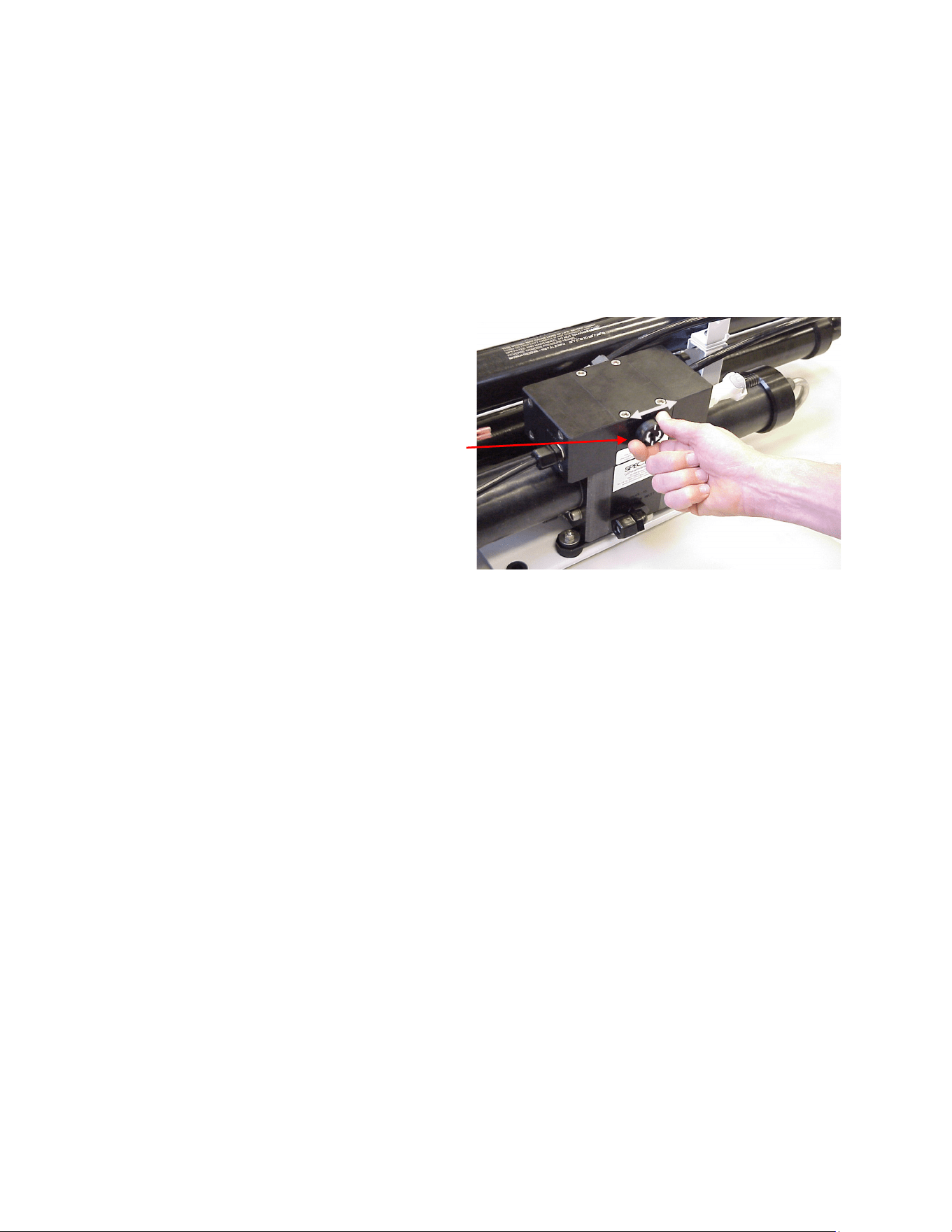
SF-2: ADJUST SHURFLO PRESSURE SWITCH
The Shuro feed pumps are equipped with a high pressure cut out switch (EL-FP-PS). This is
the small black unit on the end of the weed end of the pump head (PL-PMP-SFPH) where the
two red wires connect. If the pressure switch is not properly adjusted the pump may cut out
each me the Clark pump cycles and the feed pressure spikes. When this happens the
producon will drop and an unusual noise will be heard when operang on two pumps, but
the system will funcon normally during one pump operaon on either pump. The points in
the switch will fail fairly fast if set too low because of the constant arcing from cung out each
me the Clark pump shis.
For all systems except the Gulfstream the feed pump pressure switches should be set as
follows. On the very center of the switch is a small 5/64” Allen screw. Run the system on
pump one and close the brine discharge valve (1/2 way 90 deg), or kink the discharge hose, to
block the ow. Watch the pressure gauge and adjust the pressure switch to shut o at 125
psi. Repeat for pump two. Turn the Allen screw clockwise to increase the cut o set point.
Gulfstream models could experience seal failures in the manifold if pressurized too high. For
this reason the pump should be removed from the system and the switch adjusted using a
separate pressure gauge. If replacing a feed pump or pump head for a Gulfstream model
arrange to preset the switch before installaon.
Pressure Switch
Adjusng Screw
29
30
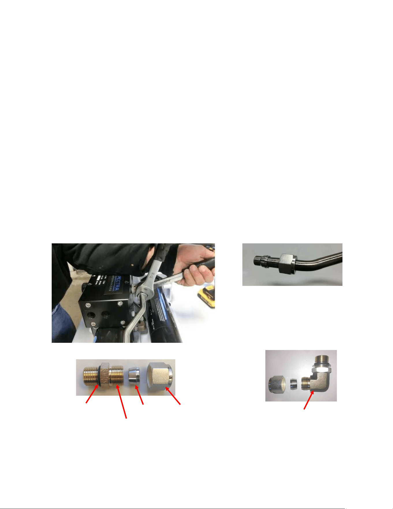
Spectra High Pressure Tube Fitting Assembly Instructions
The Aquifer has eight high pressure ngs, two on each cylinder on the Clark Pump, two on the
pressure vessel end caps, and two 90-degree elbows on the back of the Clark Pump. As the
compression ng is ghtened, it compresses a ferrule onto the stainless tubing, xing the
ferrule permanently to the tube and holding the compression nut capve.
The body of the ng seals to the underlying component with an O-ring. On the Clark Pump
cylinders and the end caps this O-ring is compressed by ghtening the enre ng. The O-rings
on the 90-degree ngs on the back of the Clark Pump have capve nuts and washers, which
compress the O-rings without turning the enre ng.
If a tube ng leaks it can somemes be resealed by just ghtening. You must use two
wrenches, a 13/16-inch wrench to hold the base, and a 7/8-inch wrench to turn the compression
nut. The 13/16-inch wrench will need to be thin so as not to interfere with the compression nut.
If this doesn’t work, disassemble the ng, grease liberally with silicone grease (the ferrule and
the threads) and re-ghten rmly.
The base O-rings should be gently compressed to achieve a good seal, and may be damaged by
overghtening, the washer or the base of the ng should just touch the block.
Stainless Fing Hex Nut
Connector O-RING
Nickel-Bronze High Pressure Elbow
Nickel-Bronze High Pressure Straight Fing
Ferrule
31
Part Numbers
Front View
Rear View
Plate Bracket
FM-PVB-PB
Rubber Mount
HD-RBP-RM
Plastic Spacer
HD-SPN-MKINS
Plate Bracket End
FM-PVB-PBE
Pressure Vessel End
Cap
FT-PV-EP
Pressure Vessel End Ring
FT-PV-ER
1/2” High Pressure Tube
PL-NLT-1/2HP
Stainless Fitting Hex Nut
PL-HWR-1/2HN
1/2” Stainless Ferrule
PL-HWR-1/2FR
Connector O-RING
SO-HPP-CT
3/4”-16 Straight Thread O-RING
SO-FT-STF
STAINLESS STEEL HIGH
PRESSURE ELBOW
PL-MTE-3/4SX1/2
STAINLESS STEEL HIGH
PRESSURE STRAIGHT
FITTING
PL-MTS-3/8X1/2S
CLARK PUMP
KIT-HP-10R
PRODUCT OUTLET
FITTING
PL-FTE-1/8X1/4P
NIPPLE
PL-NP-1/8N
Note: Aquifer 360 has two membranes
and pressure vessels. Only one is pictured
above.
32
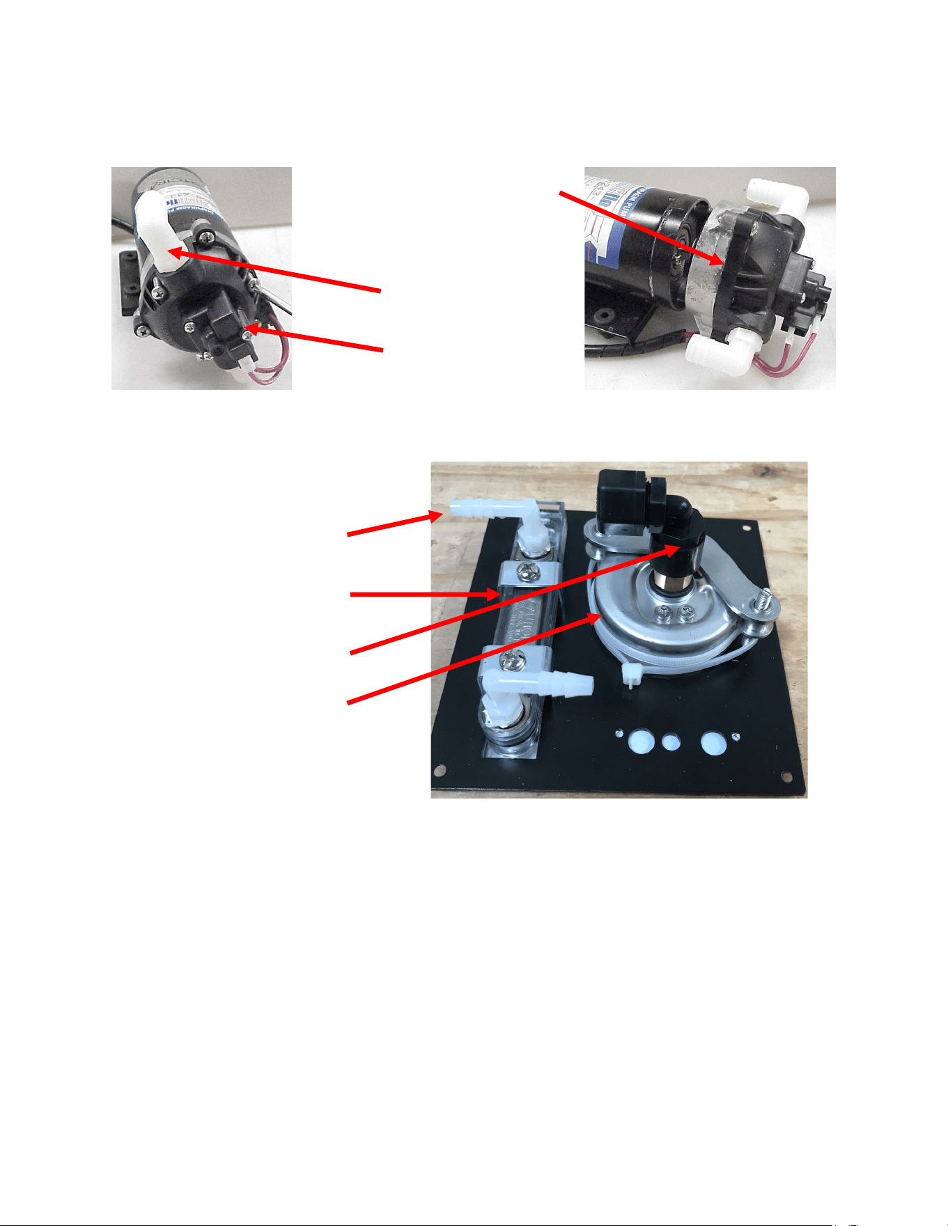
Part Numbers
Complete Feed Pump 12Volt, EL-FP-12V, (24Volt) EL-FP-24V
3/8”NPT X 5/8” Hose Barb
Elbow PL-HBE-3/8X5/8
Pump Head Assembly W/Press. Switch
PL-PMP-SFPH
Feed Pump Pressure Switch
EL-FP-PS
PL-HBE-1/8X1/4
1/8MPT X 1/4 TUBE EL
PL-FMT-10
PRODUCT FLOW METER
PL-FTE-1/4X1/4P
1/4FPT X 1/4 TUBE EL
PL-PSG-2.5L
PRESSURE GUAGE

33
PL-SWF-1/2X1/2
1/2"NPT X 1/4" TUBE
SWIVEL FITT ELL
PL-BSH-3/4X1/2N
3/4" X 1/2" HEX BUSHING
REDUCER NYL
FT-FTC-5
5 MICRON FILTER
ELEMENT (INSIDE)
FT-FTH-10H HIGH
PRESSURE FILTER
HOUSING(BLACK)
PL-NLT-1/2LP
1/2" LOW PRES-
SURE TUBE
1/8" NPT X 1/4" HOSE BARB
ELL NYLON
PL-ACC-TK
ACCUMULATOR
TANK
PL-BSH-1/2X1/4N
1/2" X 1/4" HEX BUSHING
REDUCER NYL
PL-PSG-LP2.5
2.5"D,1/4"NPT PRESS.
GAUGE 0-200PSI
PL-FMT-10
FLOW METER (10G)
PL-FTE-1/4X1/4P
1/4"FPT X 1/4"TUBE FITTING ELL
FM-AQ-FBF
FILTER BRACKET
FIXED
FM-AQ-FBH
FILTER BRACKET
HINGED
PL-SWF-1/2x1/2T
1/2”NPT x 1/2” TUBE
SWIVEL TEE POLY
PL-MTE-1/4x1/4J
1/4”NPT x 1/4” TUBE
FITTING ELL JG
Part Numbers
34
HP-TB-VEB-B
HP-TB-VB
HP-TB-VEB-A
HP-TB-BV
HP-CB-CB7
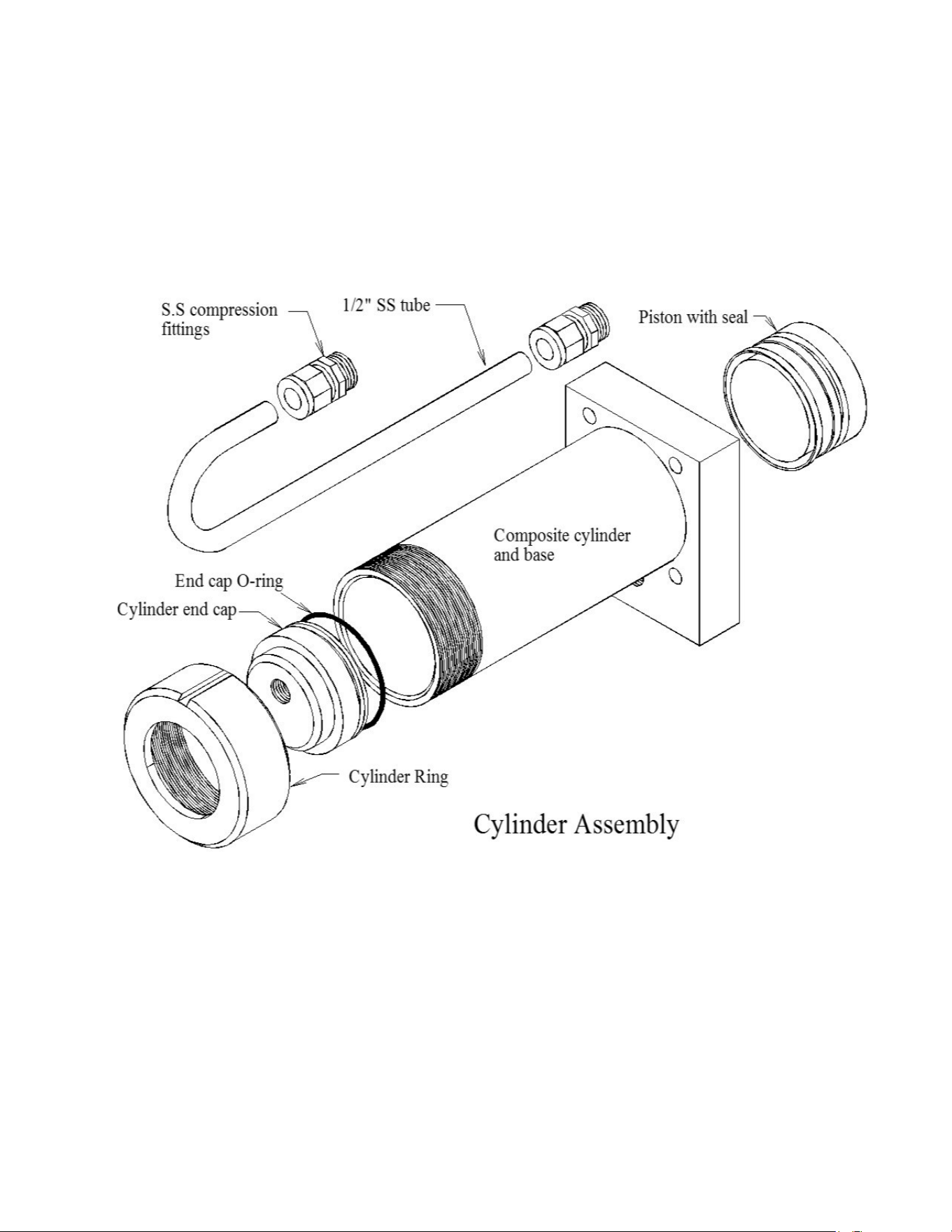
HP-CYL-SST
HP-CYL-R
HP-CYL-EC
HP-CYL-CCA
Not used
35
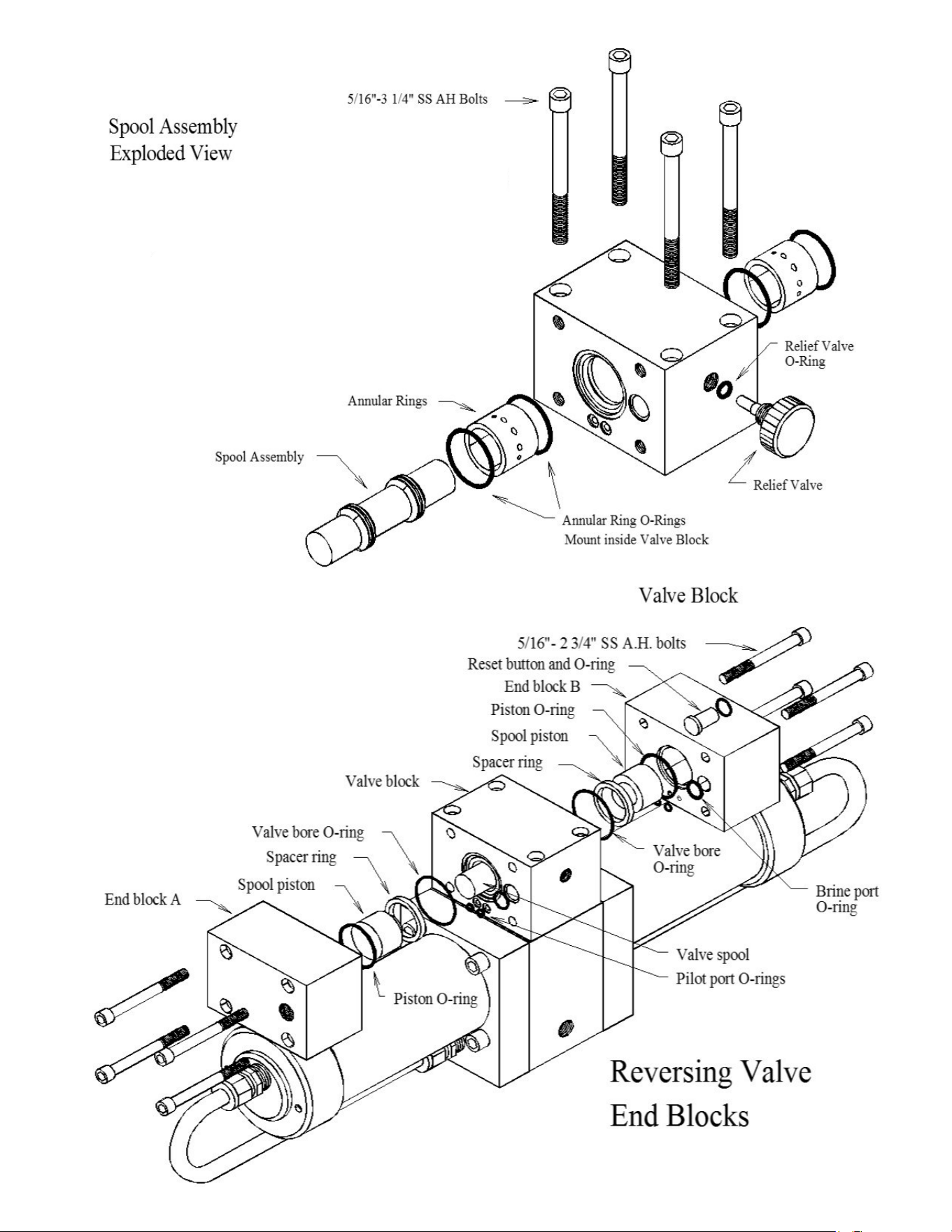
HD-CPS-5/16X3
KIT-HP-10VSA
HP-TB-ARP
SO-HPP-AR1
SO-HPP-RV
HP-TB-BV
HD-CPS-5/162.75
SO-HPP-SP
HP-TB-VSP
HP-TB-SR
SO-HPP-VB
SO-HPP-PLP
SO-HPP-VP
36
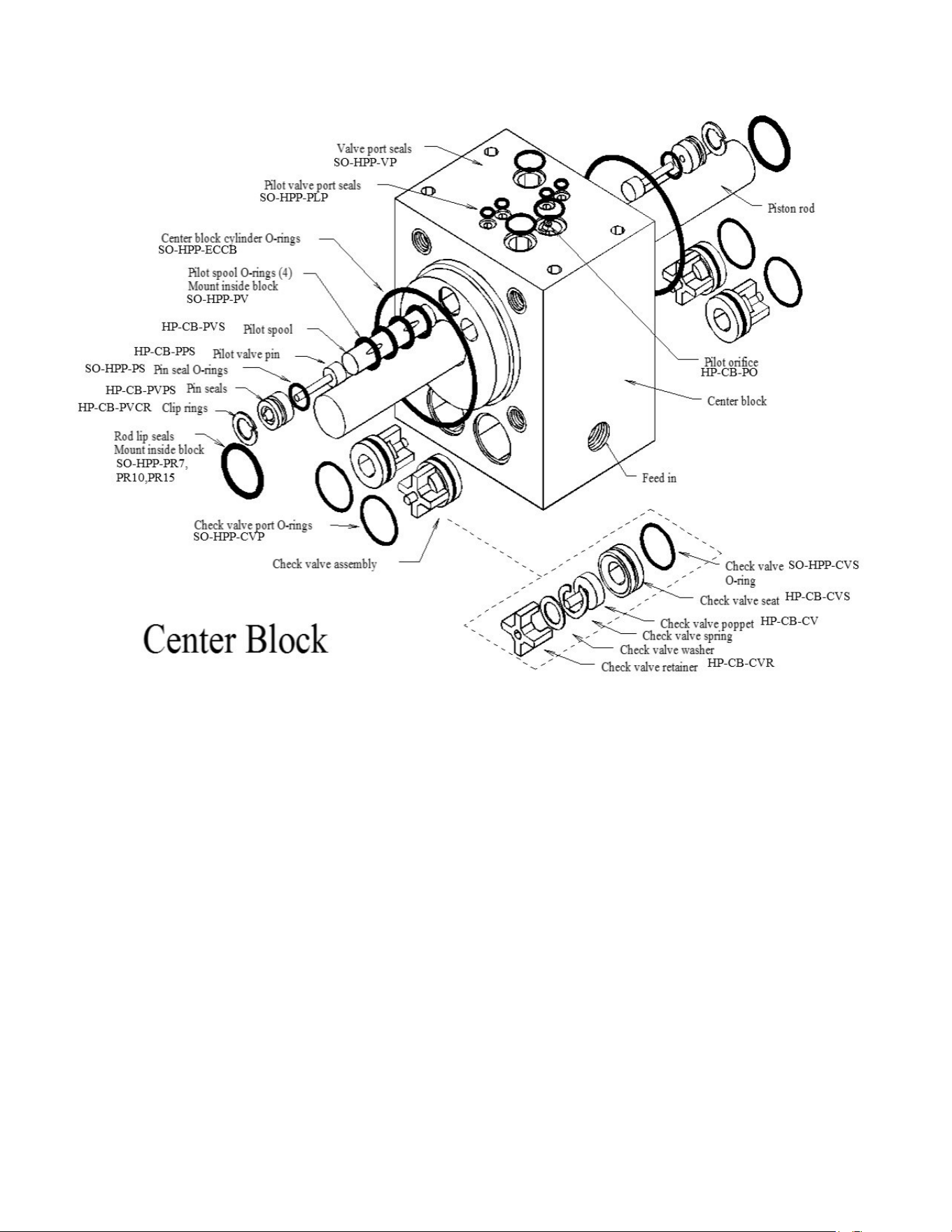
Parts
HP-CYL-3/4R,
37
PL-MTS-3/8X1/2B
HP-CYL-SST
HP-CYL-CCA SO-HPP-ECCB
HP-CYL-EC
HP-CYL-R
HP-CYL-PT
Parts