
Bimini 300
Installation and Operating Manual
Spectra Watermakers
Katadyn Desalination LLC.
2220 S. McDowell Blvd Ext. Petaluma, CA 94954
Phone: 415-526-2780 Fax: 415-526-2787
info@spectrawatermakers.com
www.spectrawatermakers.com
Updated January 2024

2

3
Outboard powered boats are one of the fastest growing segments of the
Marine industry today. Gasoline powered outboard motors present unique
safety challenges for electrically controlled marine equipment like
watermakers. With these challenges in mind, Spectra has designed the rst
watermaker specically congured for this excing class of boats, the Bimini
300.
The Bimini is the rst watermaker to be cered Ignion Protected for use on
gasoline powered boats. Non-sparking switches and a state-of-the-art
brushless DC motor are ulized to make sure all components comply with the
strictest federal guidelines. This safe, convenient system is versale, modular
and easily maintained.
The Bimini 300 is also fully automated with the Spectra Connect system making
it the simplest watermaker ever to operate and maintain, as well as allowing
mobile access and control from a phone, tablet or computer. Data logging, Fill
Tank, Auto Flush, and built-in Maintenance Interval schedules put the Bimini
300 into a class of its own.
The Spectra Bimini 300 greatly extends the range and versality of the modern
outboard powered vessel.
4
8”
20 cm
14” / 35.56 cm
5
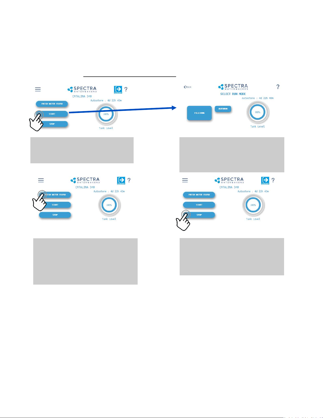
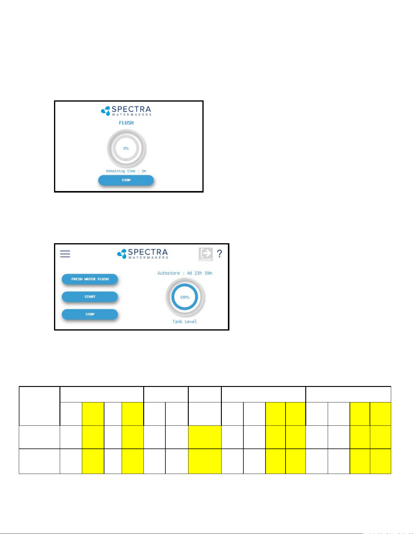
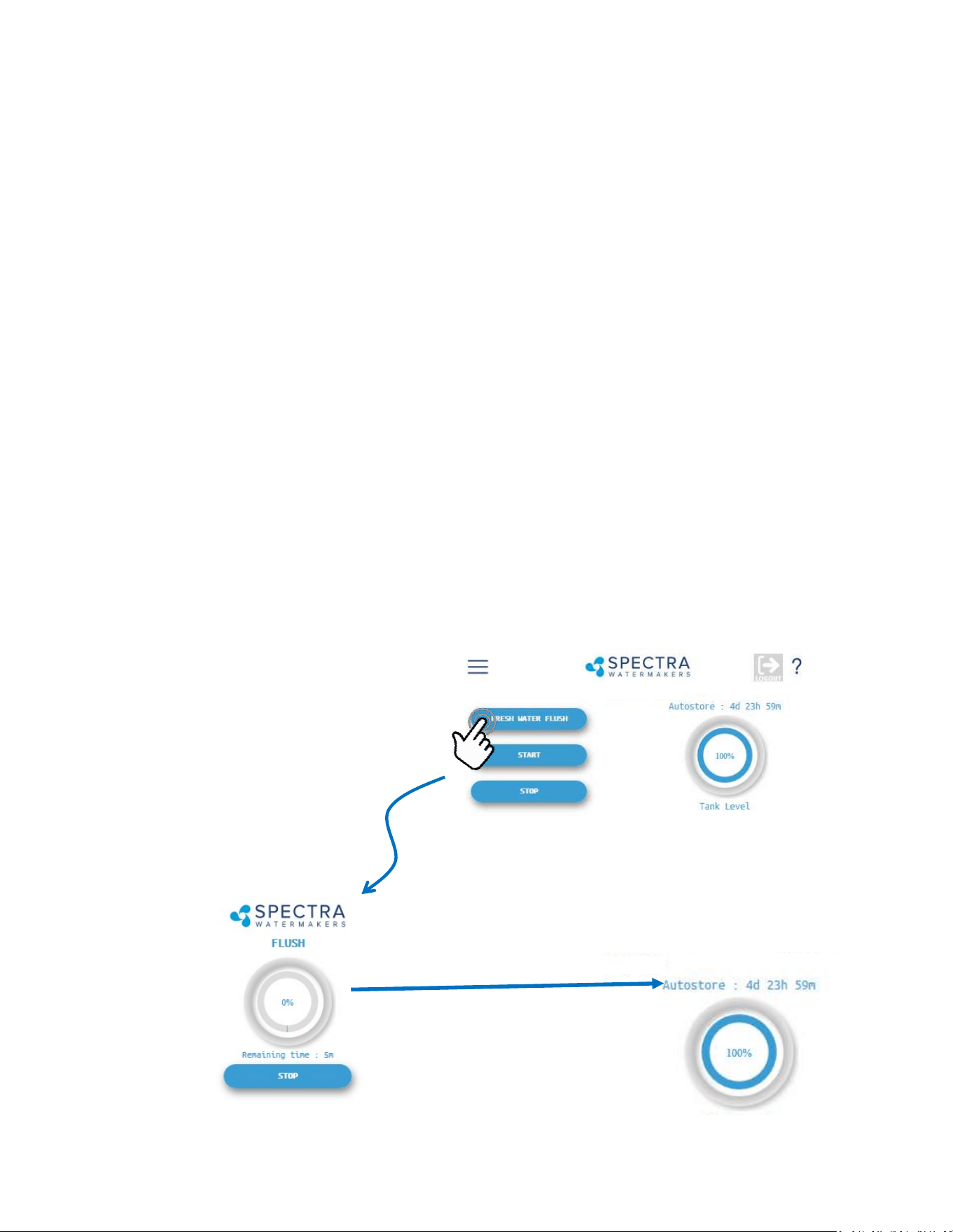
Fresh Water Flush
Pressing the ‘Fresh Water Flush’ button flushes
the watermaker with fresh water from the ves-
sel’s domestic water tanks. After completing
the flush, Spectra Connect will automatically
enter the Auto Store mode.
Stop
Pressing the ‘Stop’ button from the Home
Screen will end the Auto Store mode count-
down timer and leave your watermaker in
Standby mode.
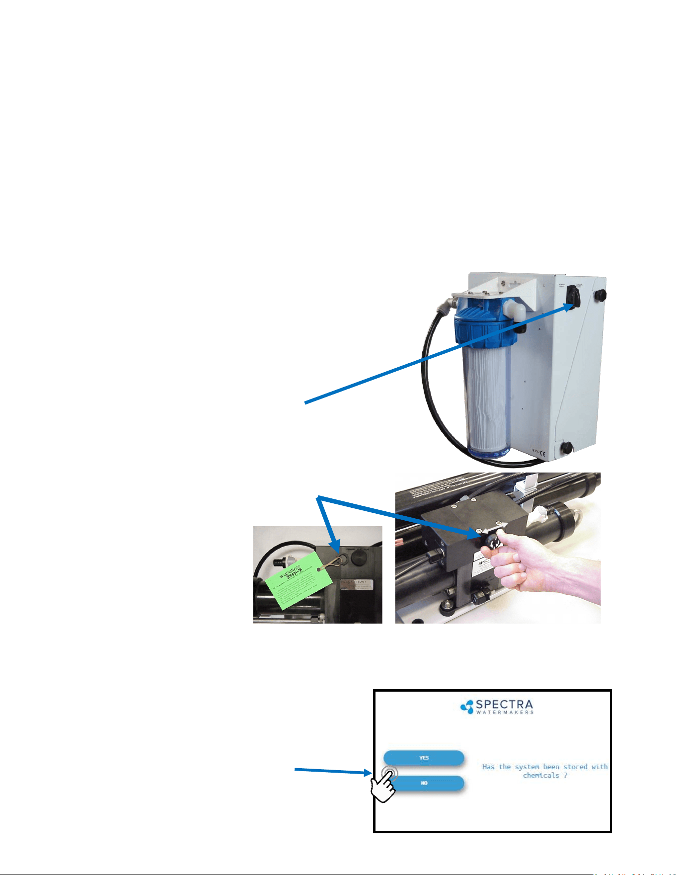
When you rst power up the system, you will get a warning message, asking if the system has
been stored with chemicals.
If the system has been pickled, winterized, this is the rst startup, or the condion of the
system is unknown, go to COMMISSIONING on page 32 or serious damage may occur.
Start
Pressing the ‘Start’ button once advances to
the Run Mode selection screen.
Spectra Connect Quick Start Guide
Run Mode
Select your desired Run Mode to start making
water and filling your tanks. See details on Run
Mode options on p. 37
Spectra Connect Modes and Denions
Auto Store: Aer the watermaker fresh water ushes, it will start a countdown mer that can be
seen on the Home screen. The mer indicates the next programmed fresh water ush if the wa-
termaker is not started again, or the ‘Stop’ buon is not pressed.
Fill Tank: The watermaker will automacally run unl the Tank Full switch in the water storage
tanks closes. Once the Tank Full switch closes, the watermaker automacally fresh water ushes,
then reverts to the Auto Store mode.
Auto Run: The watermaker can be set to run for a number of hours, or for a quanty of water to
be produced. When the desired quanty of water is produced or the run mer expires, the water-
maker will Fresh Water Flush and enter the Auto Store mode.

6

7
Thank you for your purchase of a Spectra Bimini 300 system. When properly installed and
maintained, it will provide years of trouble free service. Professional installaon is strongly rec-
ommended. Like any piece of mechanical equipment, the system will require inspecon and
service, so plan ahead for service access and install “service loops” in cabling. If a dealer is in-
stalling the system for you, review the locaon of the components to ensure the installaon
will meet your approval upon compleon.
Bimini Installation Quick Start
Important Details for Installer
1. The system must have a dedicated sea water inlet to guarantee a constant ow of water to
the system. The inlet should be as low in the boat as possible with a dedicated, forward-facing
scoop-type thru-hull ng.
2. Both the Bimini 300 feed pump module and the Clark Pump/Membrane module must be
installed in a well venlated compartment where temperatures will not exceed 113°F (45°C).
Many engine compartments exceed this temperature when underway. Warranty will be void if
the installaon does not meet this requirement.
3. Follow the wire gauge charts in the instrucons! Using larger wire than specied is accepta-
ble.
4. If you are separang the Clark Pump/membrane assembly, please review the high pressure
tube assembly instrucons. Improper assembly will cause failure!
5. Run, test, then sea trial the complete system before assuming it is operaonal. If the boat is
in fresh or dirty water, see Dry Tesng the System. Aer tesng, make sure the ush cycle op-
erates properly. The water going overboard at the end of the ush should measure <1000 PPM
Total Dissolved Solids.
6. The Spectra Connect control must have DC power connuously to achieve the full benets
of the fresh water ush system. The domesc fresh water pressure must be on and the fresh
water tank level maintained. Calculate about 7 gallons (27 liters) per ush.
7. The Spectra Connect control must be de-powered (DC power o) aer the system is pickled
or winterized.
8. Spectra dealers are responsible for educang the vessel owners on the operaon and
maintenance of the system. Please walk through the enre installaon with our customer.
9. The equipment owner should ll out the warranty card or register online.

8
• Scan QR Code to Visit Spectra Manuals Page.
• Select System, then download the User Manual.
• Reference Commissioning Checklist for important
installaon requirements.
• Review Installaon Basics secon of Owner’s Manual
to ensure warranty compliance.
Spectra Watermakers - User Manual Online Access
hp://katadyngroup.ladesk.com/206595-Spectra-Manuals

9
Table of Contents
Geng Started .................................................................................................................. 11
Installaon Basics .............................................................................................................. 12
Components ...................................................................................................................... 13
Bimini Plumbing Schemac & Plumbing Detail ................................................................ 15
Plumbing Detail ................................................................................................................. 16
Tube Fing Assembly Procedures .................................................................................... 19
Electrical & Remote Display Installaon ........................................................................... 20
Oponal Z-Ion Installaon and Instrucons ..................................................................... 23
Installing a Remote Display...............................................................................................27
Tank Switch Wiring and operaon .................................................................................... 28
Oponal Tank Level Sensor Installaon ........................................................................... 30
Operaon ....................................................................................................................... 31
New Systems Start Up and Tesng ................................................................................... 32
Dry Tesng with an Arcial Ocean .................................................................................. 34
Sensor Calibraon ............................................................................................................. 35
Tank Level Sensor Calibraon ........................................................................................... 37
Salinity Calibraon ............................................................................................................ 39
Product Flow Calibraon .................................................................................................. 40
Networking ........................................................................................................................ 41
Normal Operaon ............................................................................................................ 43
Maintenance, Storage, and Troubleshoong ...................................................... 49
Maintenance ..................................................................................................................... 50
Introducon to Spectra Chemicals ................................................................................... 53
Storage Procedures ........................................................................................................... 55
Winterizing with Propylene Glycol ................................................................................... 56
Membrane Cleaning Procedure ........................................................................................ 57
Suggested Spares .............................................................................................................. 58
Troubleshoong ................................................................................................................ 59
Alarm Override and Manual Operaon ............................................................................ 60
Bimini Flow Test ................................................................................................................ 62
Poor Water Quality ........................................................................................................... 64
Technical Bullens ............................................................................................................ 65
Spectra Connect Programming & Controls .......................................................... 69
Introducon ...................................................................................................................... 70
User Sengs & Fault Alarms ............................................................................................ 71
Dealer Access Sengs ...................................................................................................... 72
Wiring Schemac .............................................................................................................. 76
Electrical Specicaons ..................................................................................................... 77
Exploded Views and Part Numbers ........................................................................ 79
Owner Resources ......................................................................................................... 91
Warranty, Product Registraon, Installaon & Commissioning Reports ......................... 92

10
Installation Notes

11
Unpack the system and inspect it for damage during shipping. Freight damage must be report-
ed to the carrier within 24 hours.
Refer to the shipping list for your system to ensure you received all of the components listed.
Do not discard any packaging unl you have found and idened all of the parts. The small
installaon parts are listed on the kit list.
Warning! We will not be held responsible for shortages that are not reported within thirty
days of the ship date.
Study the system layout diagram, component photos, and descripons before beginning in-
stallaon.
Lay out the system. Before starng the installaon idenfy where each module and compo-
nent will be placed. Ensure that there is enough clearance around the components for remov-
al of lters and system service. Make sure you have adequate tubing and hose before starng.
Addional parts may be ordered.
Getting Started
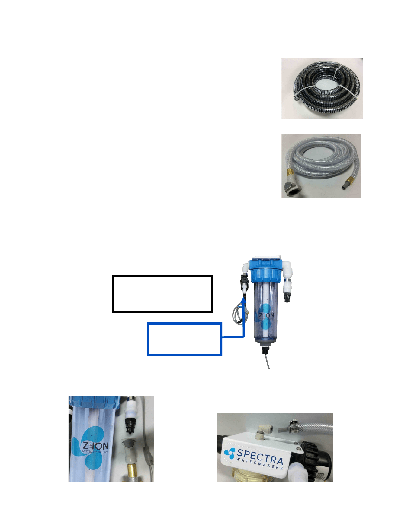
Bimini 300 Shipping List:
• Bimini Feed Pump Module
• 10% Clark Pump and Reverse Osmosis Membrane Module
• Boost Pump and Sea Strainer Module
• Fresh Water Flush Module or Z-Ion
• Service Kit
• 3/4-inch Black Spiral Sucon Hose (25 feet)
• 5/8-inch Vinyl Hose (25 feet)
• 3/4-inch Vinyl Hose (10 feet)
• 1/2-inch Vinyl Hose (25 feet) ed with Quick Connect Fing on
one end, and John Guest stem ng on the other end.
• 1/4-inch Black Product Tubing (25’)

12
Installation Basics
• Read the direcons!
• Avoid ght hose bends and excessive runs.
• Use heavy gauge wire.
• Install feed pump module as low as possible.
• Boost pump module must be installed below the waterline.
• Use a dedicated thru-hull with scoop-type strainer.
• Do not mount components over electrical devices.
• Avoid geng dirt or debris into the piping or hoses during
assembly. A small bit of debris can stop the system!
Thru-hull Locaon: The system must be connected to a dedicated 3/4” to 1” forward-facing
scoop-type intake thru-hull and seacock.
Install the thru-hull intake as far below the waterline and as close to centerline as possible to
avoid contaminaon and air entering the system. Do not install the intake close to, or down-
stream of, a head discharge, behind the keel, stabilizer ns, or other underwater xtures.
Thru-hulls in the bow area are suscepble to air intake in rough condions. Sharing a thru-hull
can introduce unforeseen problems such as intermient ow restricons, air bubbles, contami-
nants, and will void the warranty. For racing boats and high speed boats traveling above 15
knots, a retractable snorkel-type thru-hull ng is preferred because it picks up water away
from the hull.
The brine discharge thru-hull should be mounted above the waterline, along or just above the
boot stripe, to minimize water li and back pressure.
Double clamp all hose connecons below the waterline.
Avoid restricons or long runs on the enre inlet side of the plumbing from the thru-hull to the
feed pump module.
Secure the piping away from moving objects such as engine belts and hatches. Prevent chafe on
the tubing as required. Test and inspect all piping and hose clamps aer several hours of opera-
on.
Pipe Fing Instrucons: To seal plasc-to-plasc ngs, wrap 6 to 8 layers of Teon tape over
their threads. Hold the ng in your le hand and ghtly wrap the threads clockwise. For
smoother assembly, do not tape the rst (starng) threads.
Wiring
• Pay aenon to wire size or system performance will be impaired
• Perform wiring to UL, ABYC, CE or applicable standards
Seawater Flow
Thru-hull
Not Supplied.
13
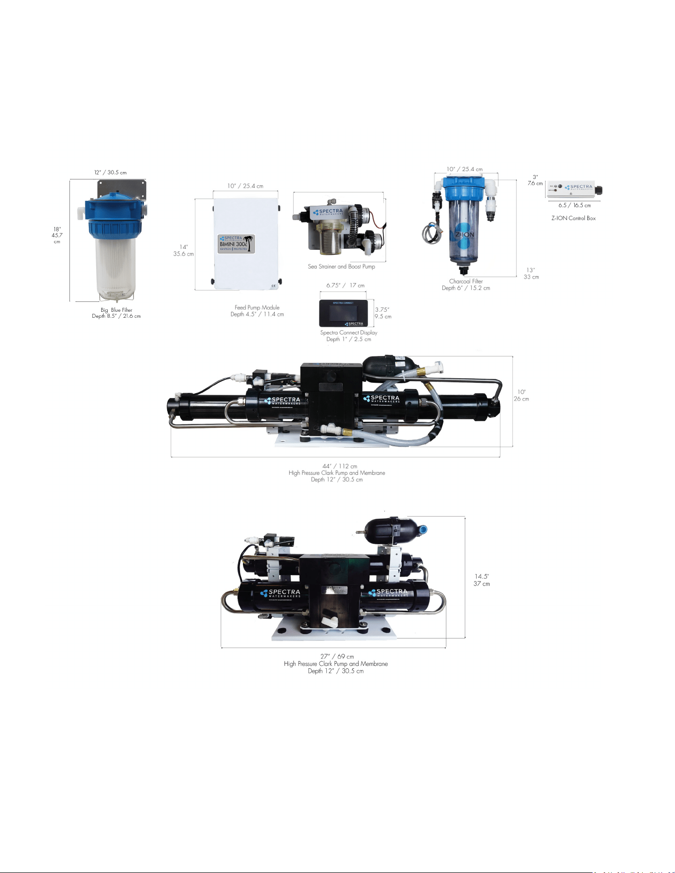
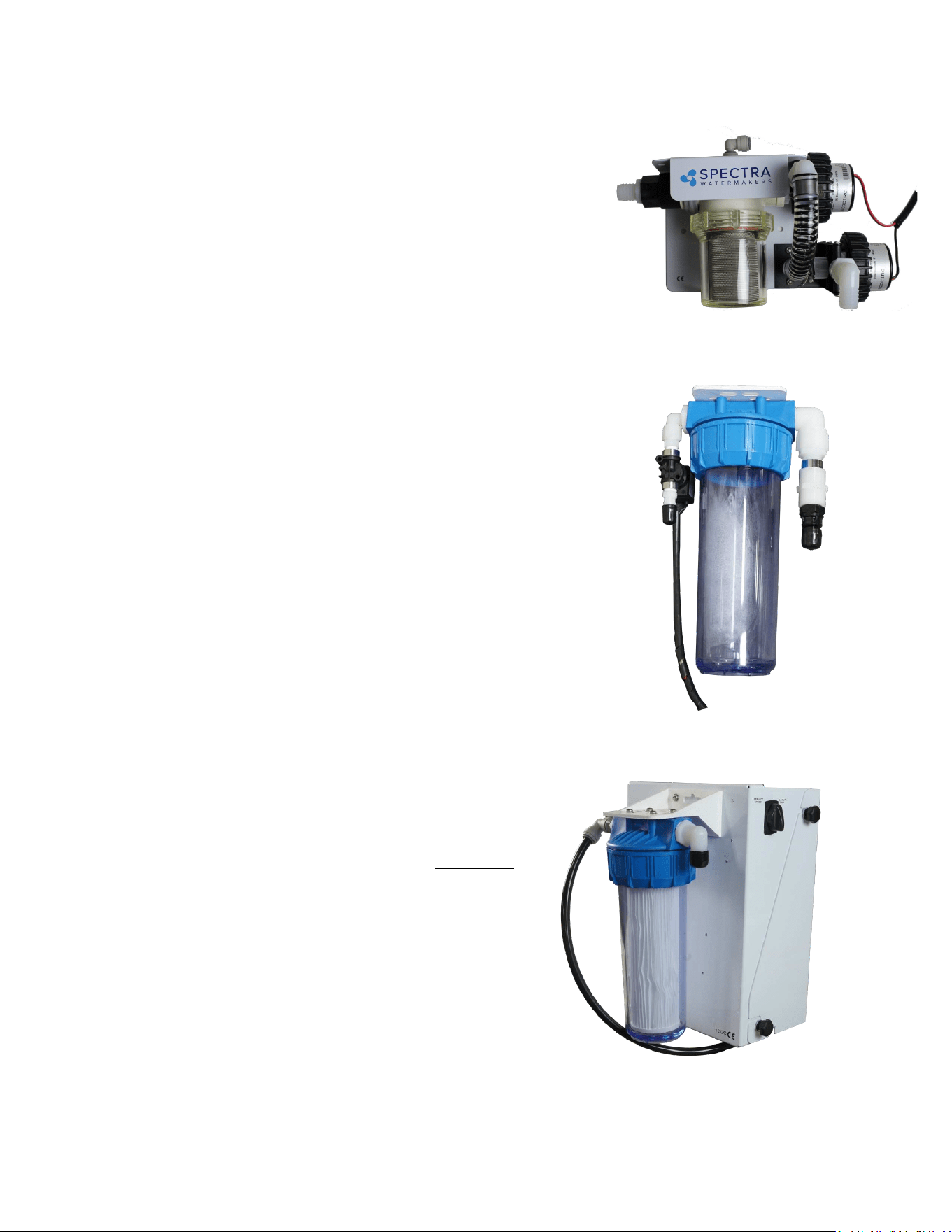
Feed Pump Module
Mount the feed pump module on a vercal surface, up
to 3-feet (1.0M) above the waterline. It is preferable to
mount as low as possible. Locate in an area that allows
easy access to both the lters, and the le and right
side of the enclosure (3 inches or more). Keep future
maintenance in mind when choosing a locaon, and do
not mount above water-sensive equipment. The feed
pump has overheat protecon and will not operate
properly at ambient temperatures over 113°F (48°C).
Sea Strainer and Boost Pump Module: Mount close to the
intake through-hull, below the waterline, in a locaon that
can handle water spillage during service. The boost pump
power cable will connect to the feed pump module.
Fresh Water Flush Module: The fresh water ush module may be
located in any convenient locaon near the feed pump module. It
should be mounted with the lter housing vercal and accessible,
with 2” below the housing for lter changes. Do not install over
electrical equipment. The unit contains the charcoal lter, a
solenoid shut o valve, and a ush water ow regulator.
IF INSTALLING THE Z±ION, SEE Z±ION INSTALLATION
INSTRUCTIONS FOR MORE DETAILS.
Components

14
Double rubber mounts
to absorb vibraon
This module must be installed in an area that maintains a temperature below 113°F (45°C). It
may be placed as high in the boat as you desire, and mounted in any posion, even upside
down. Make sure that the area around and under the pump does not have any water sensive
equipment, as water will be spilled during any repairs or if a leak occurs. Allow for easy access
to the pressure relief valve.
The Clark pump and membrane module comes complete with a mounng system. Be sure to
use the supplied washers on the rubber feet.
Pressure Relief Valve
Components - Cont.
Clark Pump and Membrane
Remote Touchscreen
The remote control panel can be mounted anywhere dry and
convenient. Cut a 5-5/8” (12.7 cm) wide by 3-1/4” (7.62 cm)
high opening for the panel. The display needs minimum 2
1/2” deep clearance for the cable. Take care not to damage
the plugs on the ends of the cable when roung. Use only a
Spectra-approved cable.
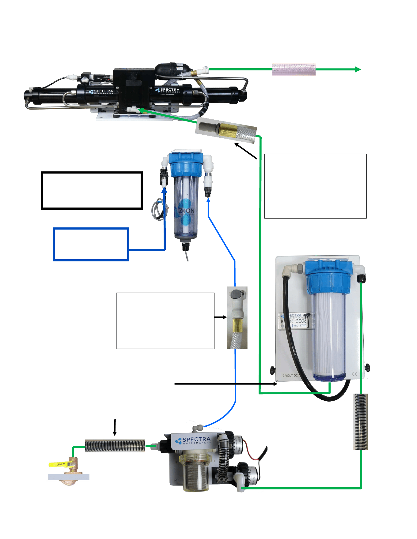
15
Use the supplied 3/4” (19mm)
sucon hose (clear with black spiral)
from the inlet thru-hull to the boost
pump/sea strainer module, and from
the boost pump/sea
strainer module to the
From the Clark pump brine discharge
connector use the supplied 5/8 (16 mm)
clear braided vinyl hose with Quick
Connect ng to the brine overboard
Plumbing Schematic
Flush water from ship’s
pressure water system
25 psi (2bar) minimum
Use part of the 25-feet (8 meters)
of 1/2-inch vinyl hose, pre-ed
with a 1/2-inch John Guest stem
ng, to connect the feed pump
to the Clark Pump feed water inlet.
(see following pages)
Use the 1/2-inch vinyl hose with
the Quick Connect ng
between the Z-Ion/fresh water
ush module and the top of the
sea strainer. (see following
pages)
The oponal Z-ION will
replace the Fresh Water
Flush module
16
Plumbing Detail
Your system includes 25-feet of 1/2-inch vinyl hose with a Quick
Connect ng on one end and a 1/2-inch John Guest stem
ng on the other, both crimped on with ferrules. You will CUT
THIS HOSE and, using the ngs found in the installaon kit,
use one end for the feed water inlet hose and the other for
the fresh water ush hose:
Fresh Water Flush: Route a feed line from the domesc cold pressure water system to the
1/2-inch hose barb on the fresh water ush module. This needs to be pressurized when the
boat is unaended for the fresh water ush system to funcon properly. The domesc fresh
water pump must be able to deliver 1.5 gallons per minute (6 LPM) at 25 PSI (1.7 bar).
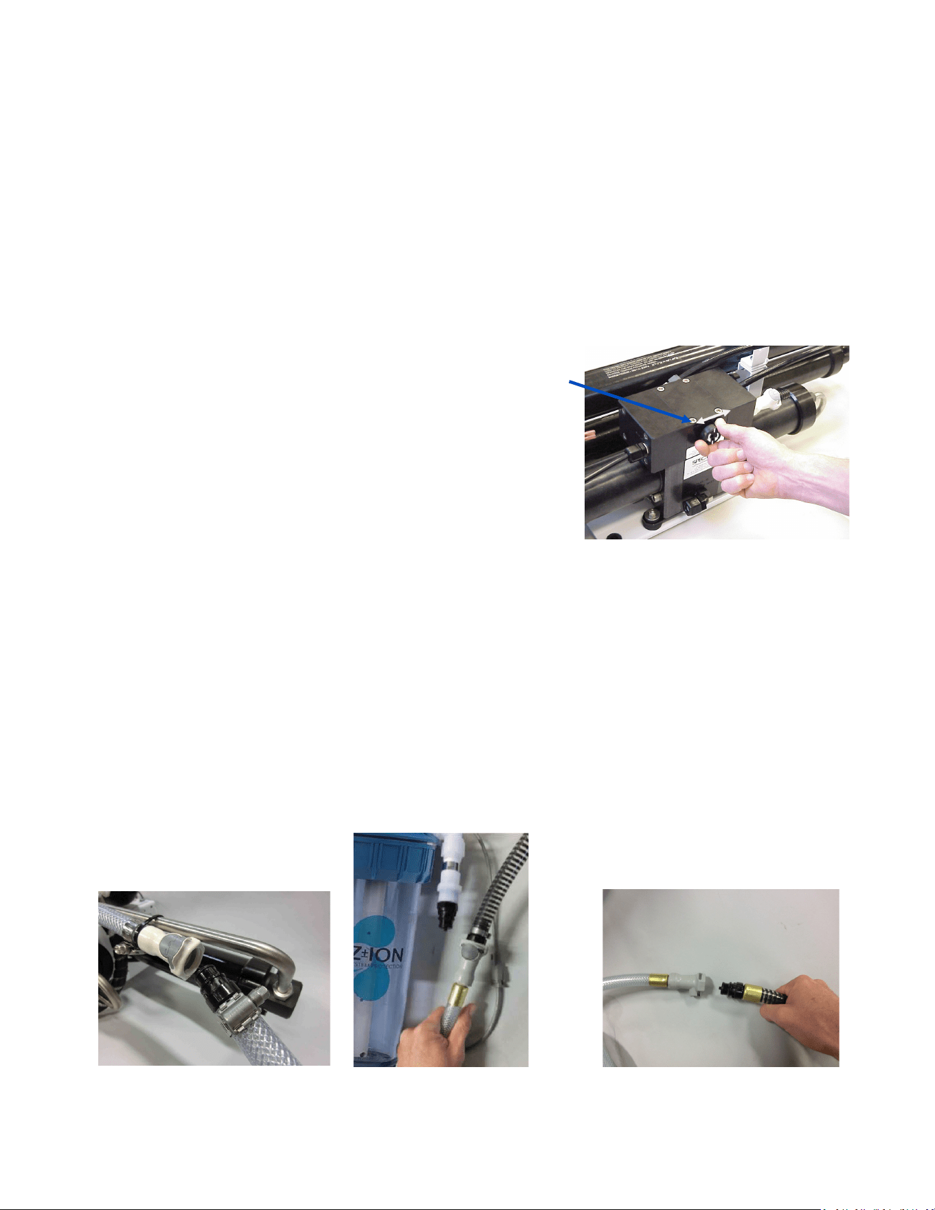
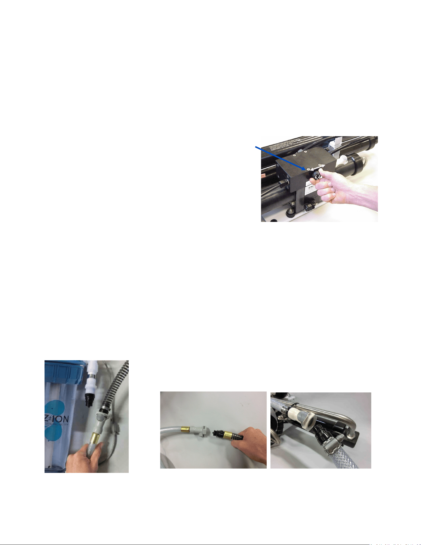
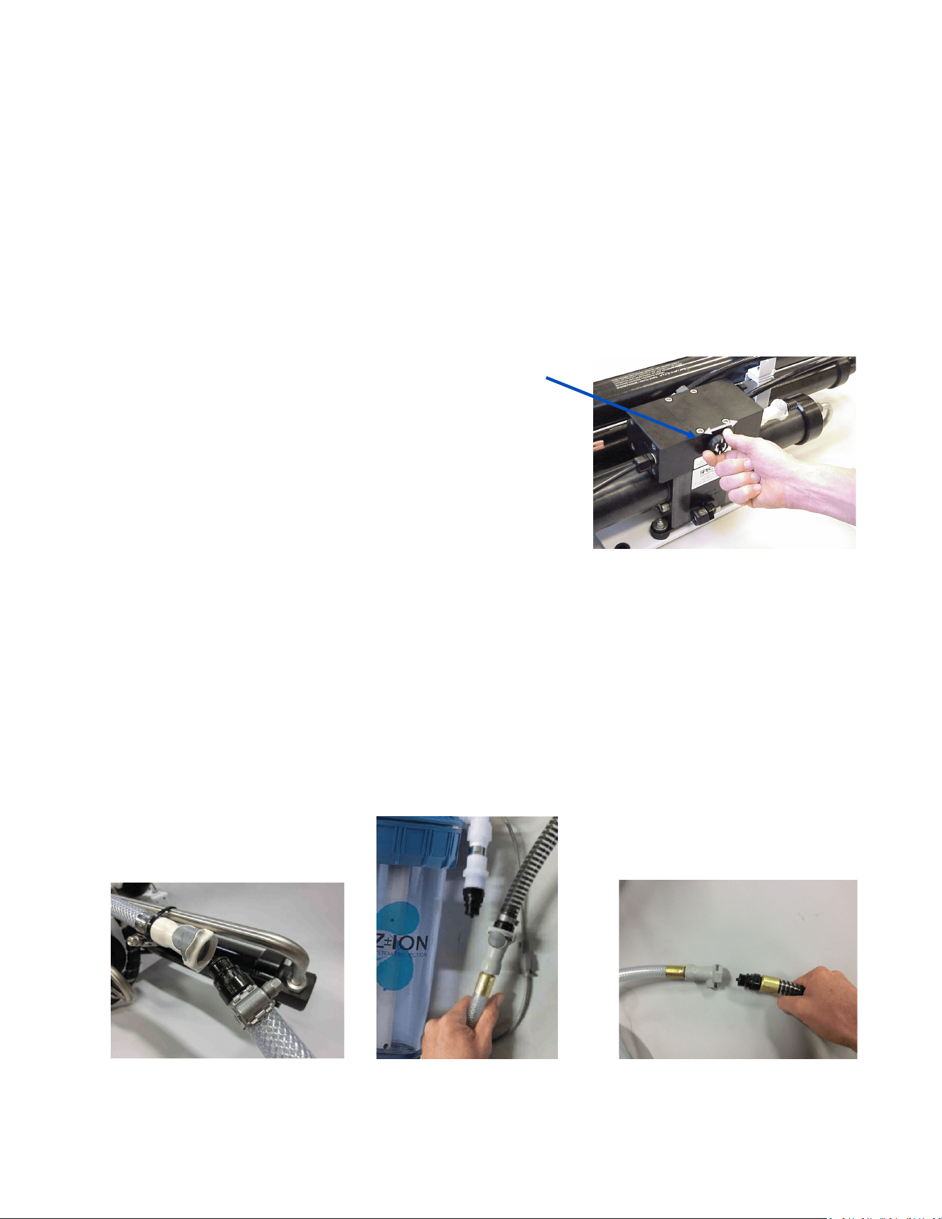
Aaching 1/2-inch vinyl hose to sea
strainer using the 3/8” John Guest
stem ng and hose clamp found in
installaon kit:
Aaching 1/2-inch vinyl hose to Z-Ion/
fresh water ush module with the pre-
ed Quick Connect ng:
Flush water from ship’s
pressure water system
25 psi (2bar) minimum
The oponal Z-ION will re-
place the Fresh Water
Flush module
From the intake seacock to the sea strainer/boost pump module,
and from the sea strainer/boost pump module to the prelter
housing on the feed pump module, use the 3/4-inch black, spiral-
wound sucon hose:
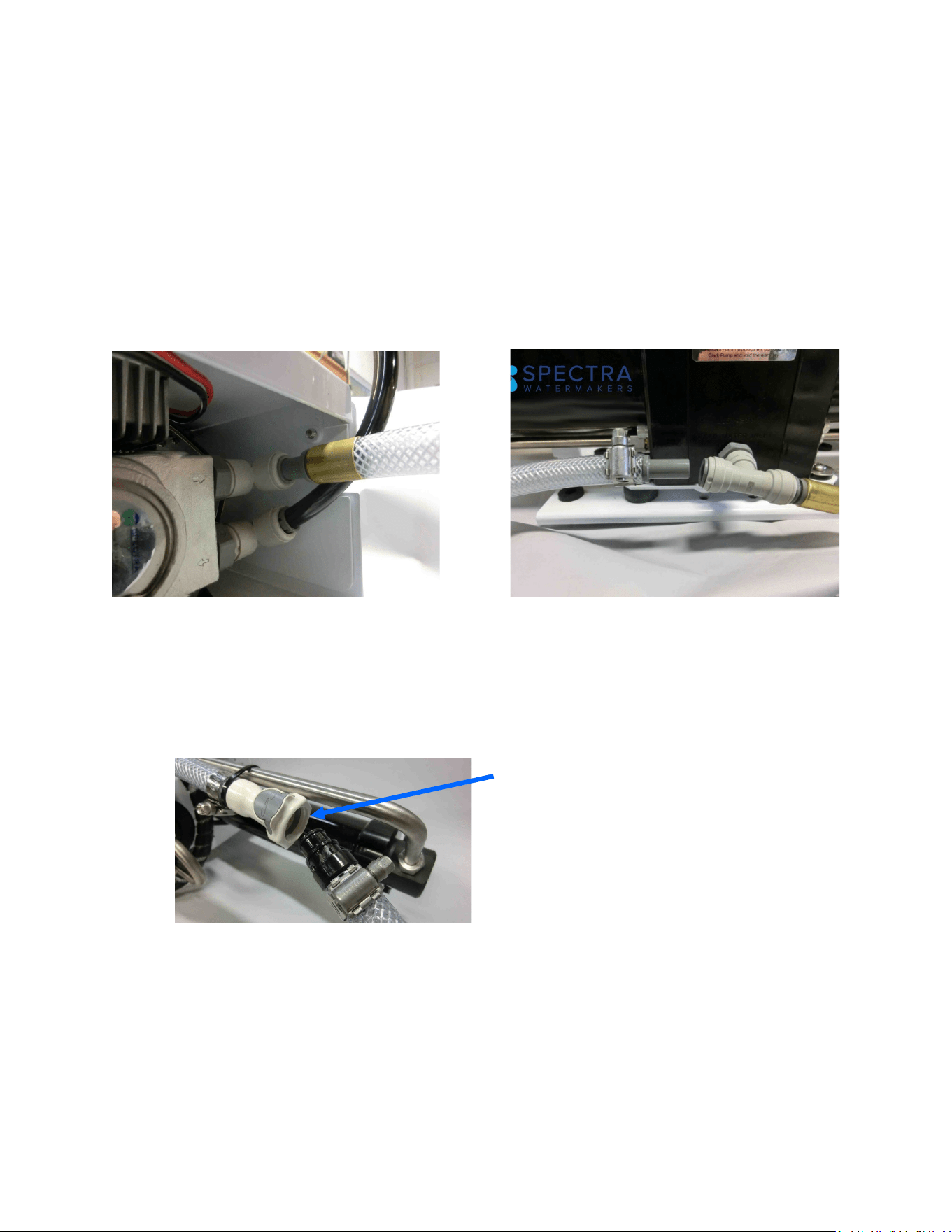
17
Quick Disconnect Fing
Plumbing Detail - Cont.
Brine Discharge: Route the brine discharge from the quick disconnect ngs to a thru-hull
above the waterline using the supplied 5/8” braided vinyl hose and the male Quick Disconnect
ng from the installaon kit:
From the feed pump to the Clark Pump feed water inlet, use the remaining 1/2-inch vinyl hose,
with the 1/2-inch John Guest stem ng pre-ed with a ferrule. Insert the pre-ed end into
the feed pump (Figure 1), and the 1/2” John Guest stem ng and hose clamp from the instal-
laon kit for the Clark Pump feed water inlet (Figure 2). Refer to John Guest assembly instruc-
ons on page 19.
Figure 1: Fig- ure 2:
18
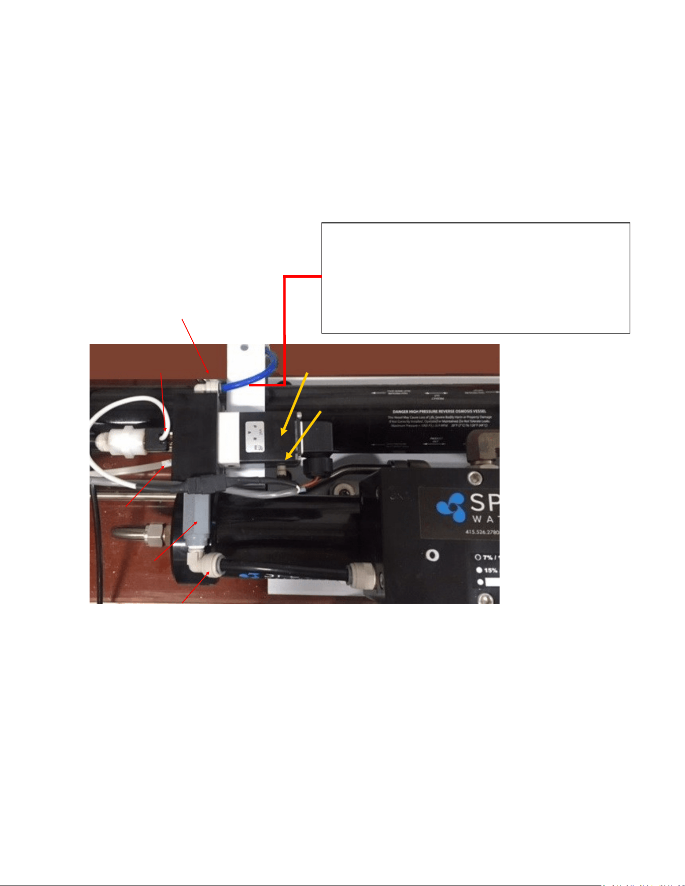
Salinity Probe (under)
Diversion Valve
The 1/4”(6mm) product water tubing is pre-plumbed from the membrane into the electric diversion
valve. The diversion valve will reject product water into the overboard brine stream unl the
Connect controller determines the product water is below 750 PPM salinity. Once below 750 PPM,
the Connect controller opens the diversion valve and product water is diverted into the fresh water
tank. The salinity probe must be mounted in a vercal posion with the cable coming out the
boom. If the Clark Pump/Membrane Module is mounted vercally or upside down the diversion
valve/probe assembly MUST be remounted in the proper orientaon.
For plumbing to the fresh water tank, see the John Guest ng assembly diagram on the next
page.
Product to tank: Route the product water into the top
of a vented tank, or a tee in the water tank ll hose.
DO NOT feed into a vent line, manifold, or into the
boom of the tank. Bladder tanks will create too much
back pressure. There must be no restricon or back
pressure whatsoever in this piping.
Product Diversion Valve Manifold
Rotoow Meter
Accepted Product
Water Outlet
Rejected product outlet
Check Valve
Product Water Plumbing
Manual override buon
19
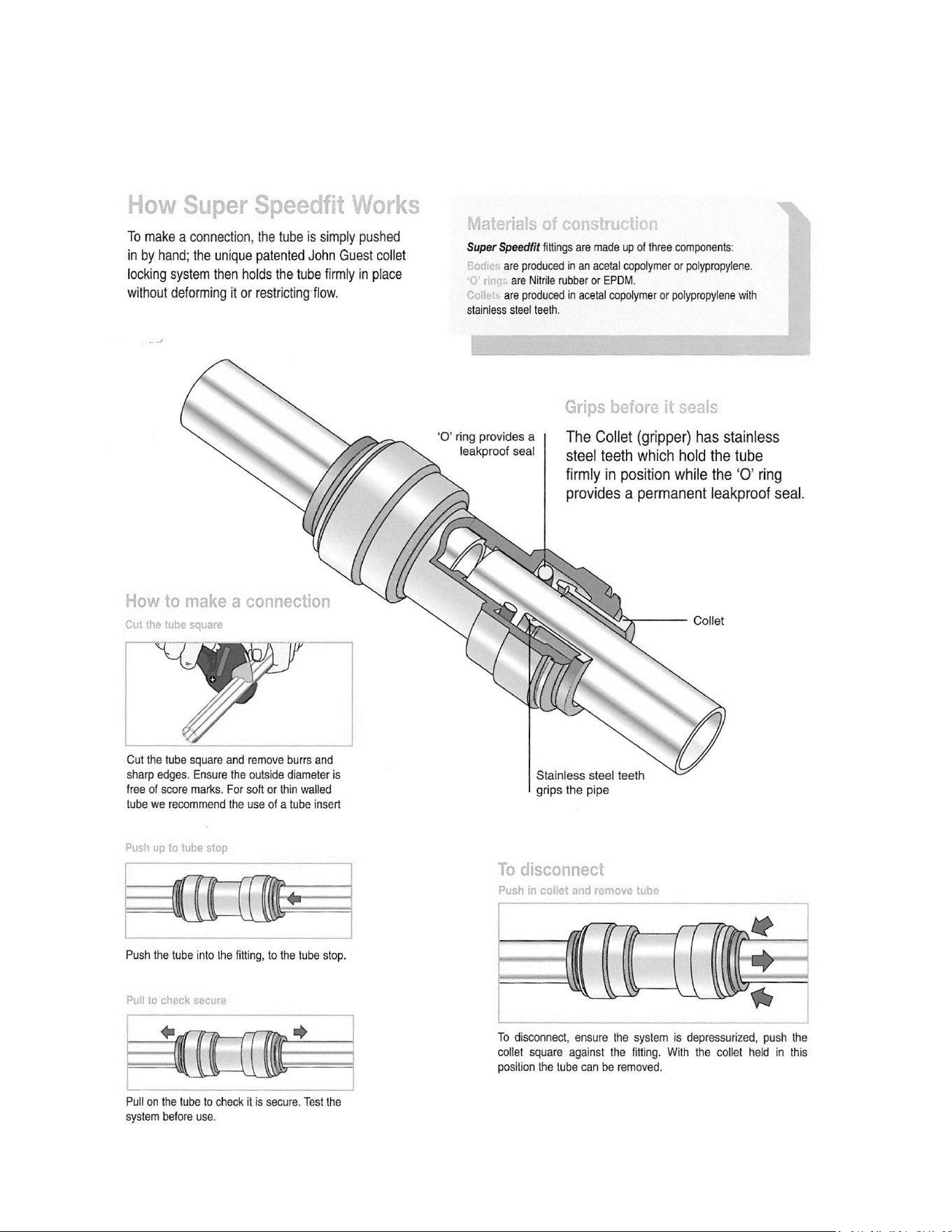
John Guest Super Speedfit Fittings
20
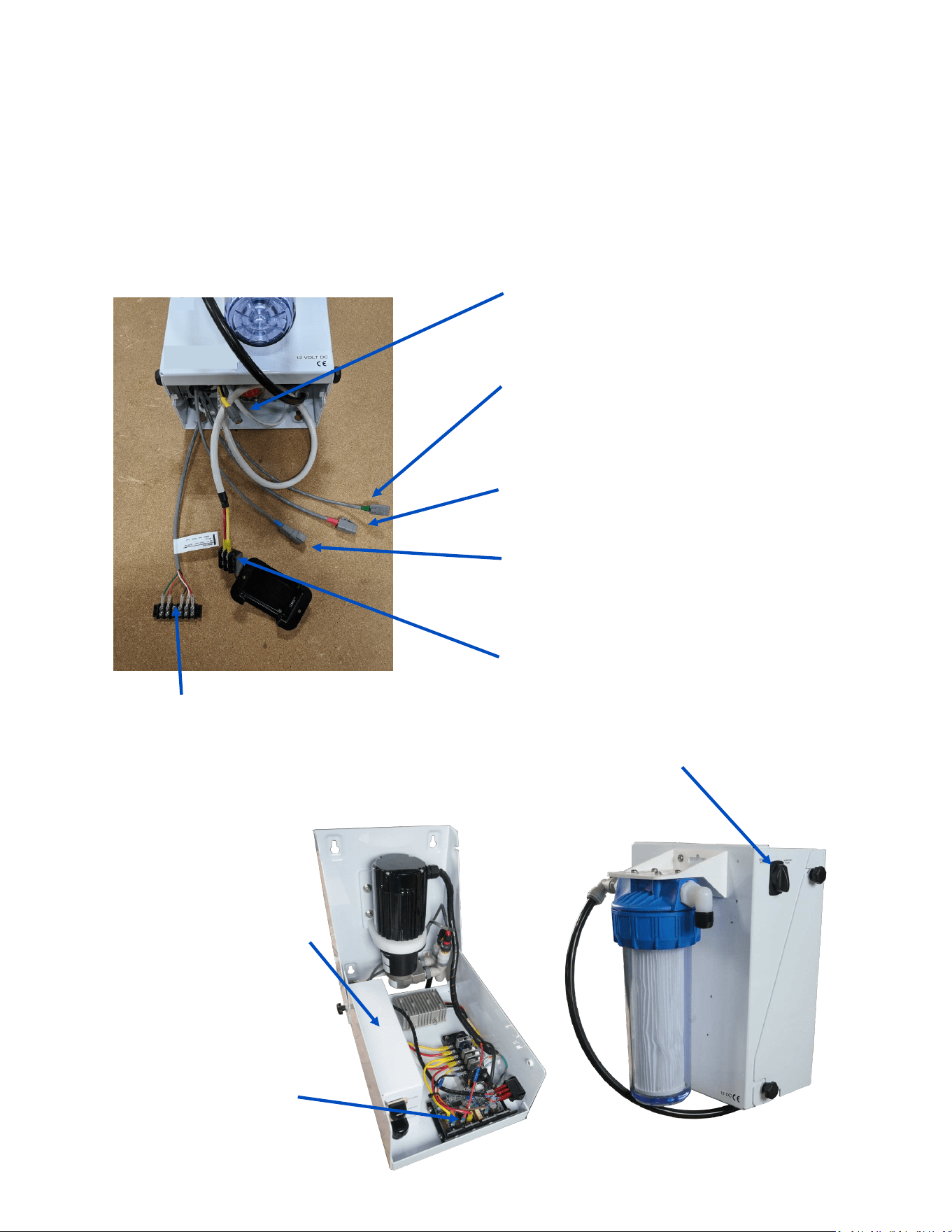
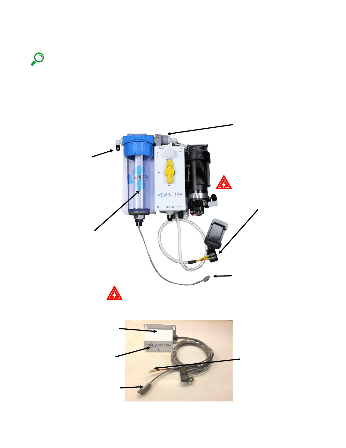
The Bimini 300 has a power inlet harness with a terminal block and cover, a boost pump
power plug with a yellow band, terminal block for the tank full switch and the oponal tank
level sensor, and a short plug with a green band for the oponal Z-Ion.
Do not install it in hot or poorly venlated locaons. Allow access to the motor speed
control.
Power inlet harness
with terminal block
Boost pump cable (Yellow)
Brushless Motor speed
controller
Spectra Connect
controller (Inside control
Run Auto/Manual/Service
toggle switch
Electrical
Z-ION Connector (with green band). Le
unused if your system was not ordered
with the oponal Z-ION.
Tank Full Switch
Terminal Block,
Green + Orange
Tank Level sensor
5vdc: Red
Signal: White
Ground: Black
Standard Fresh Water
Flush connector (Blue)
Product manifold assemble (Red-
connects le of Clark Pump)
21
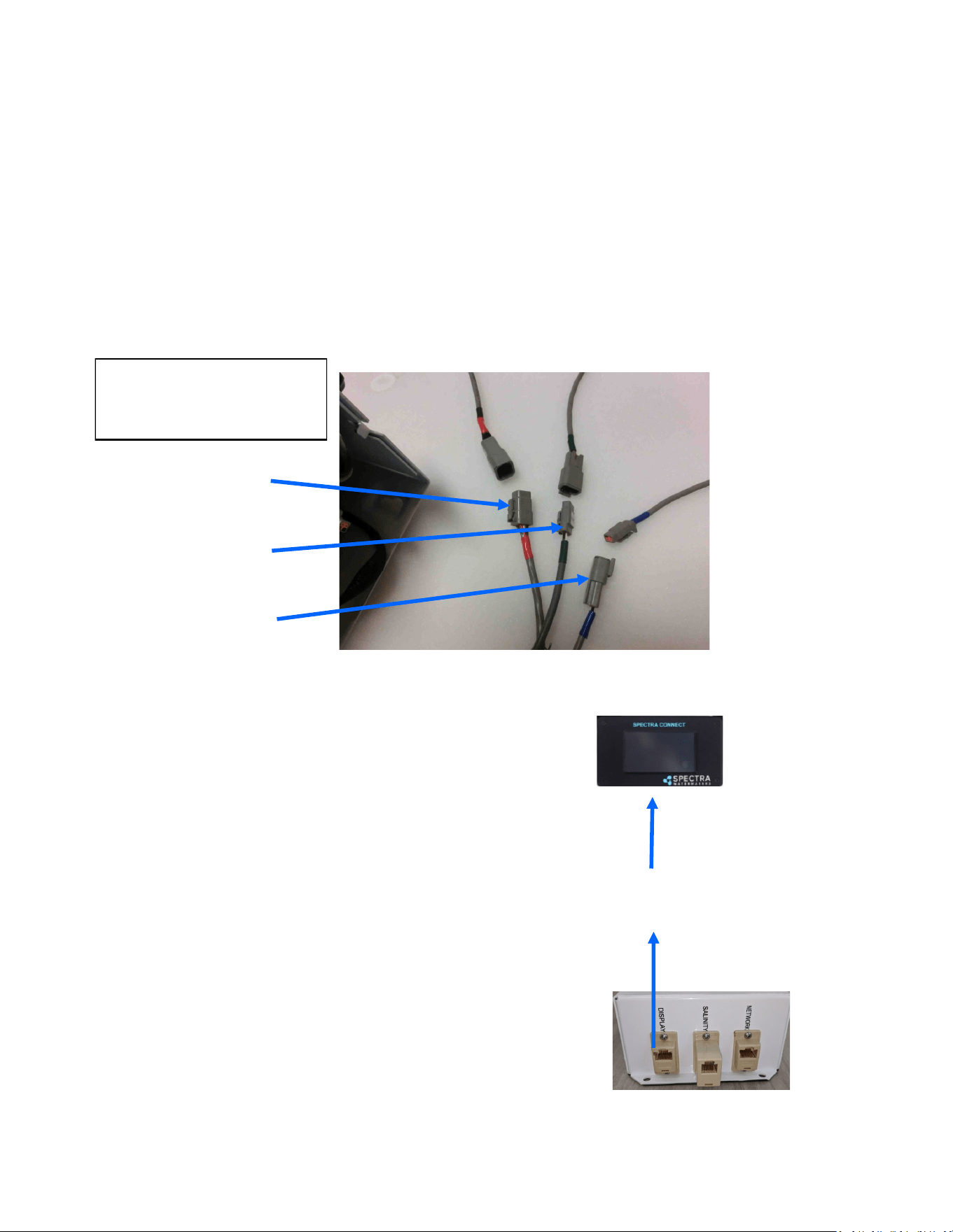
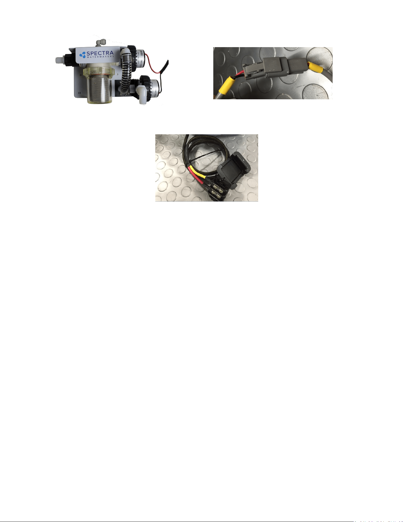
Bimini 300 systems are pre-ed with waterproof connectors for electrical and signal cables.
Each connector is dierent, so it is impossible to connect them incorrectly, and the connectors
are color-coded. The system has a power inlet harness with a terminal block and cover, a 2-
conductor boost pump cable, a 5-conductor diversion valve and Rotoow sensor cable, a 2–
conductor fresh water ush solenoid cable, a Z-Ion power and signal cable, and a 100-foot
(30.5 M) cable for the Connect display.
Diversion Valve and
Rotoow Cable (5-
conductor, Red).
Z-Ion power and signal
cable (3-conductor,
Green)
Cables are shown coming
out of the boom of the
Feed Pump Module.
Fresh water ush sole-
noid cable (2-conductor,
Blue)
100’ (33.3M) cable with
connectors for the connect
display
The Bimini 300 has three ports that
can be viewed when looking down
inside the Feed Pump Module; one
for the display, one for networking,
and one for the salinity probe. The
Salinity probe is a 5 pin cable with RJ
-12 connectors (phone jack) on both
ends this cable runs in parallel. The
Display cable is a standard Cat 5e
ethernet cable.
Electrical - Cont.
22
Electrical - Cont.
Distances at le represent the total
ROUND TRIP wire length (DC posive
length plus DC negave length), NOT
the length of the pair of wires
together. Size cables accordingly.
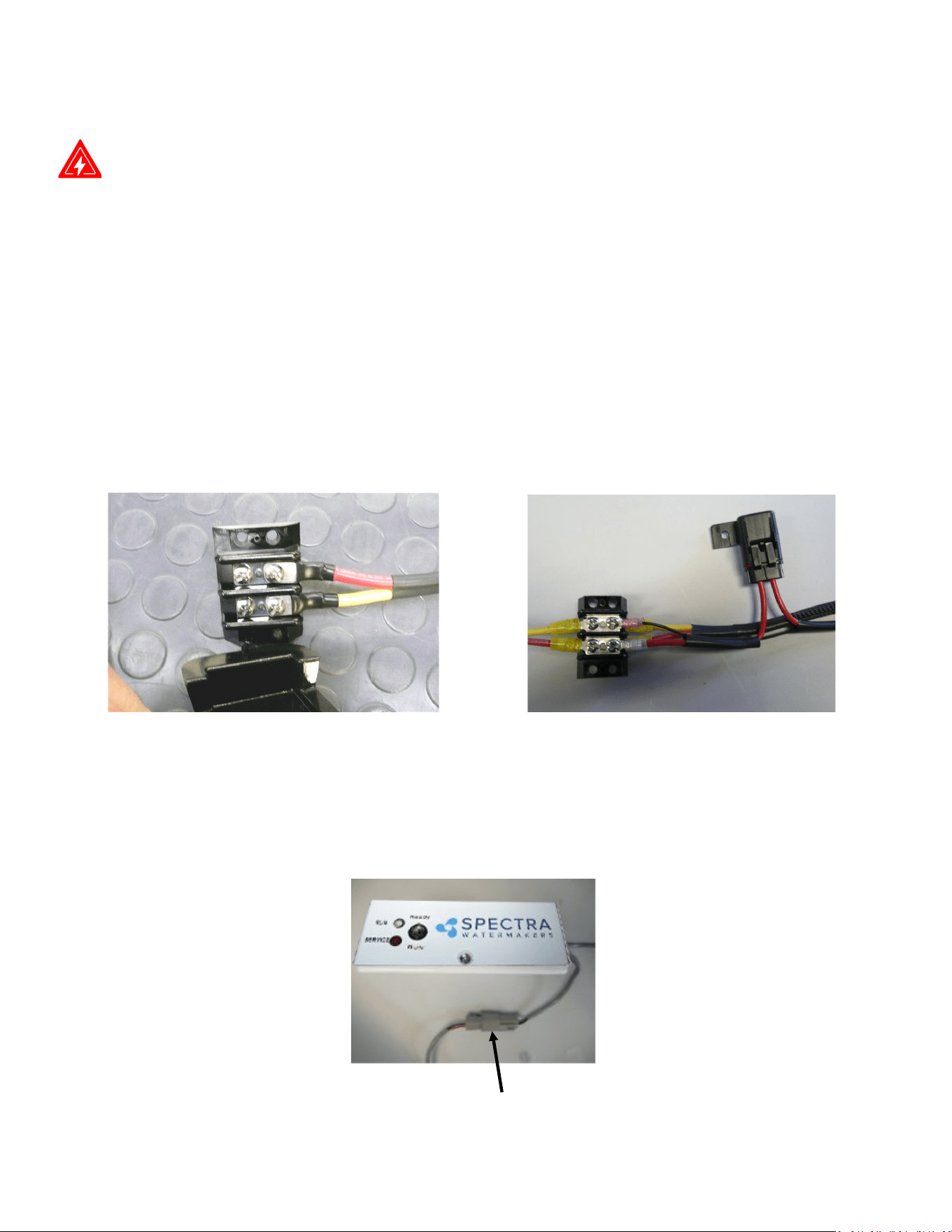
Mount the main power terminal block in a juncon box or on a bulkhead adjacent to the feed
pump module. Make sure that this is a dry locaon well above bilge level and not subject to
water spray. Be sure to install the terminal block cover.
Check the wire size chart for appropriate wire sizes. DC power feeds should be uninterrupble
to insure proper operaon of the auto store feature. Avoid house breaker panels that could be
accidentally tripped.
Component Sizing:
• 12-Volt: Use a 32A-35A breaker and size the wiring for 25 Amperes.
• 24-Volt: Use a 15A breaker and size the wire for 13 Amperes.
• Provide circuit protecon at the source! Undersized wiring will reduce system perfor-
mance.
Wire Size Guide for the Bimini 300 12 Volt:
8 Gauge (10mm²) up to 15 feet (4.5M)
6 Gauge (16mm²) up to 20 feet (7.6M)
4 Gauge (25mm²) up to 35 feet (14M)
Wire Size Guide for the Bimini 300 24 Volt:
8 Gauge (10mm²) up to 30 feet (10.6M)
6 Gauge (16mm²) up to 45 feet (14M)
Note: All wiring to be done to applicable ABYC, Marine UL, or CE standards.
Connect the yellow boost pump connector from the boom of the feed pump housing to
the corresponding connector routed from the boost pump.

23
Oponal Z-Ion Protecon System
The Z-Ion, developed by Spectra, protects the enre system from fouling for extended periods
without fresh water ushing or storage chemicals (pickling).
The Z-Ion achieves this end by introducing a stream of metallic ions into the fresh water ush
water, thus ooding the enre system with ions that prevent biological growth for up to thirty
days. If you are going to let your system sit idle for longer than thirty days, you will sll need to
treat it with SC-1 storage chemical or propylene glycol.
The Z-Ion will not prevent freezing, so in freezing climates pickling with propylene glycol is sll
required. Even with the Z-Ion there may sll be cases when you need to pickle your system
with SC-1 storage chemical or propylene glycol, so we recommend you carry one of these
products at all mes.
If your system was ordered with the Z-Ion, it will require only some basic wiring and
commissioning, laid out in the following pages.
If you didn't order you system with the Z-Ion, it can be retroed to any Spectra system.
NOTE: Contact Spectra for more informaon at: techsupport@spectrawatermakers.com
24
Z-Ion Installation
NOTE: If you did not order your Cape Horn Xtreme with the oponal Z-Ion you may disregard
this secon of the manual.
If you ordered your Cape Horn Xtreme with a Z-Ion, the feed pump module will come with the
Z-Ion installed in place of the standard fresh water ush module, as shown, with a separate Z-
Ion electronic control box:
Z-Ion control box: Mount in a
visible locaon near the feed
pump module.
Connector for generator bowl
Z-Ion power cable with in-line
fuse: Connect to the system
electrical bus or other source
of ship’s power.
DANGER
Control Box:
On/O switch
Fresh water ush valve:
manually opened at the start
of the cycle and closed at the
end.
Generator bowl with charcoal
lter.
DANGER
System electrical bus bar: Z-Ion
will connect here (or any
convenient connecon to ship’s
power).
Feed Pump Module:
Hose barb
connecon to
house pressure
water system,
with valve
Generator bowl connector
25
Z-Ion Installation - Cont.
DANGER
Z-Ion Power Connecons
Turn the main DC breaker o or remove the main power fuse to the watermaker.
Locate the DC Bus Bar for the watermaker (or any other DC power source), as shown below.
Connect the DC power leads from the Z-Ion Control Box to the Incoming DC Bus Bar.
• Pay aenon to polarity!
• Connect Red (fuse) to DC +
• Yellow (or black) to DC -
• Replace protecve cover
Z-Ion Fuse holder: Install in a dry
locaon with easy access.
Connecon from generator bowl to control box:
The pigtail form the control box has a water-ght connector, which connects to the pigtail
from the generator bowl:
26
The Z-Ion should be energized at all mes, but will only consume power when operang. Upon
inial power-up the LED will ash red/green and then will turn solid green.
Follow the instrucons for Normal Operaon and Fresh Water Flush. For treatment with the
Z-Ion, the process is idencal, only the Z-Ion will release silver and copper ions into the ush
water when you turn on the generator with the on/o switch. Turn on the ion generator at the
same me that you open the ush valve.
The operaon cycle begins and the LED will ash green/amber. The cycle will connue unl you
turn o the ion generator or the adjustable mer mes out (factory set for 15 minutes).
Turn o the ion generator at same me that you close the ush valve. If you forget to turn o
the ion generator, the Z-Ion will me out aer 15 minutes, so no harm will be done to the unit.
If the voltage is out of range, below 10V or above 56V, the LED will ash red every two seconds
and the unit will shut down.
Each fresh water ush with the Z-Ion will protect your watermaker for up to 30 days, aer
which the process must be repeated.
Aer 720 cycles the service light on the front of the control box will light up, indicang that the
probes on your Z-Ion may be wearing down, and should be tested. The service light is just a
reminder, and the Z-Ion will go on funconing while it is lit.
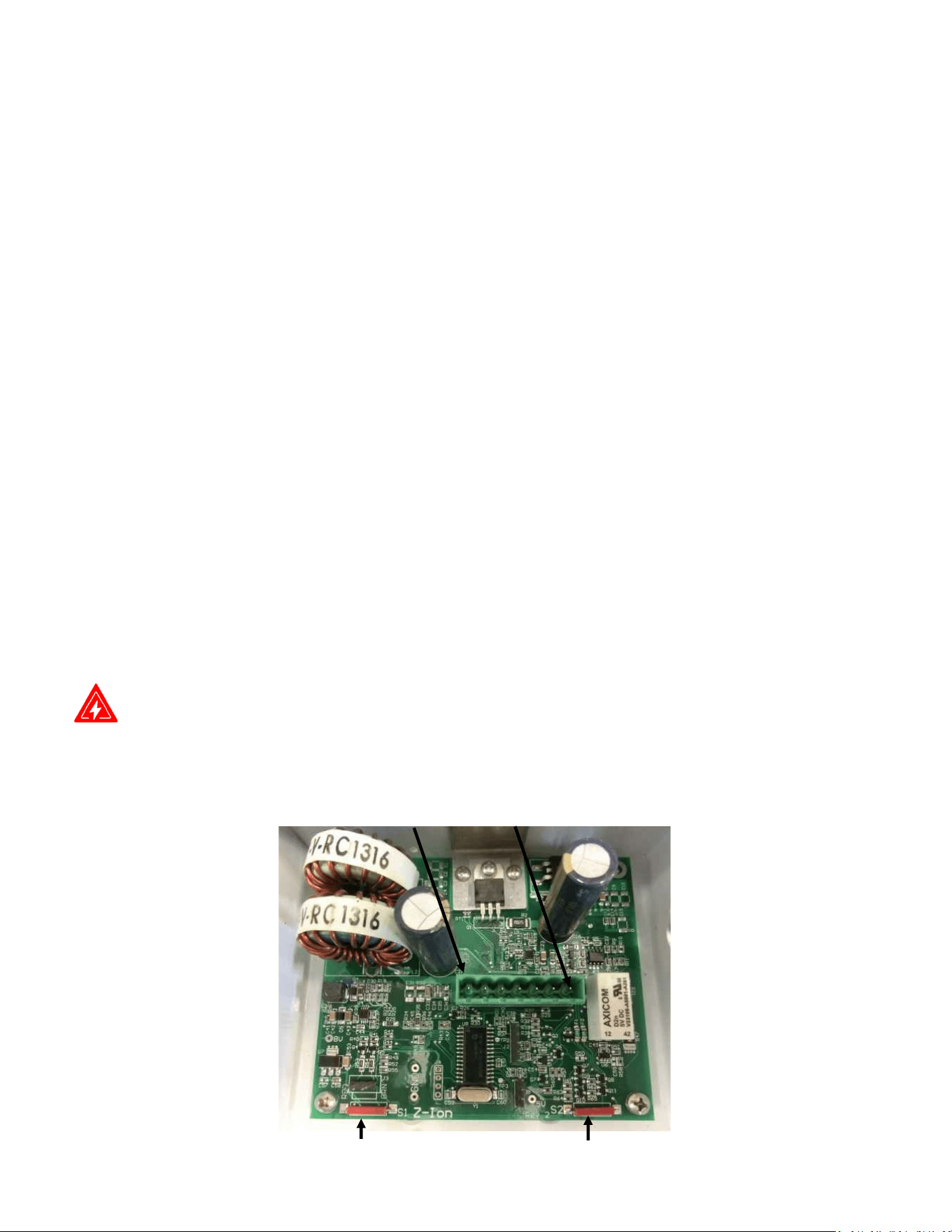
DANGER: To reset the service counter, touch two magnets, at the same me, to the two red
reed switches on the Z-Ion circuit board, labeled Switch 1 and Switch 2 below.
Z-Ion Operation
Switch 1 Switch 2
Pin 1
Pin 7
Z-Ion Circuit Board Layout
27
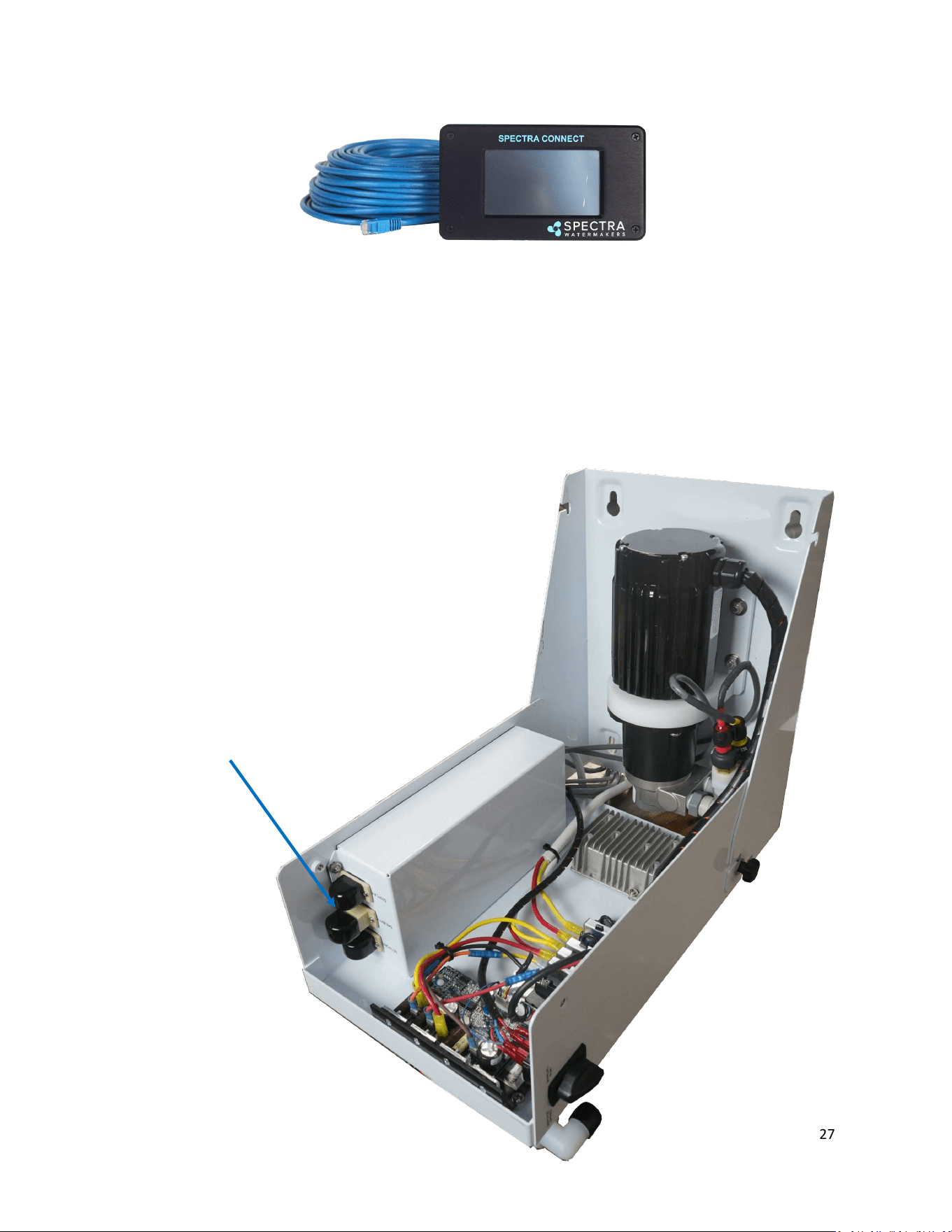
Installing a Remote Display
Route the cable through the vessel in the most direct route possible. Avoid kinking the wire,
or sharp corners where the wire can chafe through while the vessel is under way.
Turn power OFF to the system.
Connect the ethernet cable to back of the display in the open jack.
Connect the opposing end of the ethernet cable to the RJ12 port labeled “DISPLAY” in the feed
pump module.
Remote Display Plugin
28
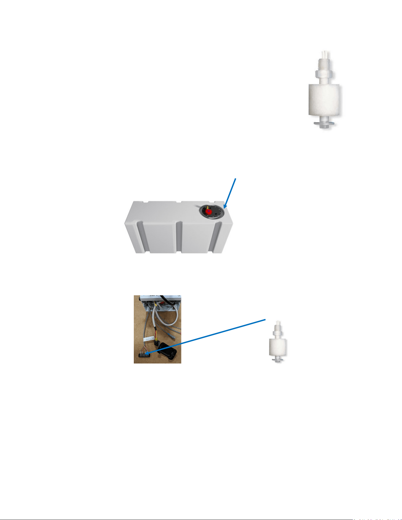
Factory Supplied Tank Full Switch
Installing the supplied tank full oat switch at the top of your water tank al-
lows the Spectra Connect to ll your water tank then automacally stop, fresh
water ush and return to Auto Store mode with no addional user com-
mands.
Note: The oat may need to be ipped 180° to work properly. The oat can
be easily ipped by removing the clip opposite the wire.
Drill and tap a 1/8” npt port into the top of the fresh water tank that is being
lled by the watermaker. This can be installed on a tank access cover, or directly into the water
tank. If installing on an access cover, be sure to leave a service loop on the oat switch wiring to
allow removal of the tank access cover.
For Instrucons on ‘Auto Fill’ mode and installing a Tank Low switch, see ‘Auto Fill’ mode
instrucons later in this manual.
Watermakers should never be run unaended.
Your watermaker comes with the top-mounted Tank Full Switch (EL-SWT-LV) and is designed
to be mounted to the top of the water tank. The side-mounted oat switch (EL-SWT-SMLV)
can be sourced from your local dealer or Full Service Provider if you cannot access the top of
your tank.
If you do not install the Tank Full switch in your tank, you MUST DISABLE the Tank Full
Switch in the system sengs. See System Sengs instrucons later in this manual.
Tank Switch Installation
The supplied oat switch must be connected to the Green and Orange conductors at the
Feed Pump Module, labeled Tank Full Switch. There is no polarity.
Use 18/2 nned wire or larger. Wire is not included in the installaon kit.
Drill and Tap
Connect to Gr/Or wires
29
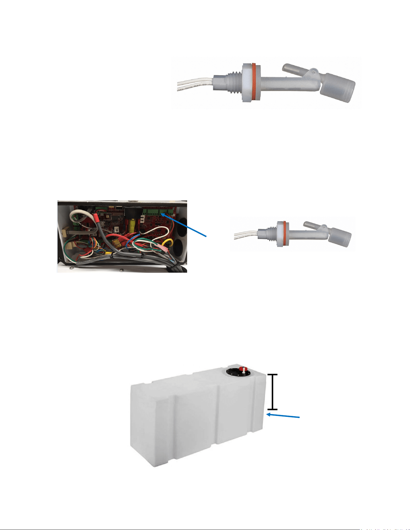
Oponal Tank Low Switch
Installing the tank low oat switch about 2/3rds down from the top of your water tank allows the
Spectra Connect to run in Auto Fill mode; automacally lling your water tank, stopping itself,
fresh water ushing, returning to Auto Store mode, and then turning itself on again to ll the tank
when the water level drops below the Tank Low Switch with no addional user commands.
Drill 5/8” hole into the side of the fresh water tank that is being lled by the watermaker. This can
be installed wherever there in convenient access to the tank, approximately 2/3rds of the way
down from the top of the tank.
Drill 5/8” hole
Tank Switch Installation
2/3
The oat switch must be connected to the Tank Switch 1 terminals on the Spectra Connect
control board at the Feed Pump Module. There is no polarity.
For Instrucons on enabling the ‘Auto Fill’ mode see the System Sengs instrucons later
in this manual.
Watermakers should never be run unaended!
Tank Switch 1
30
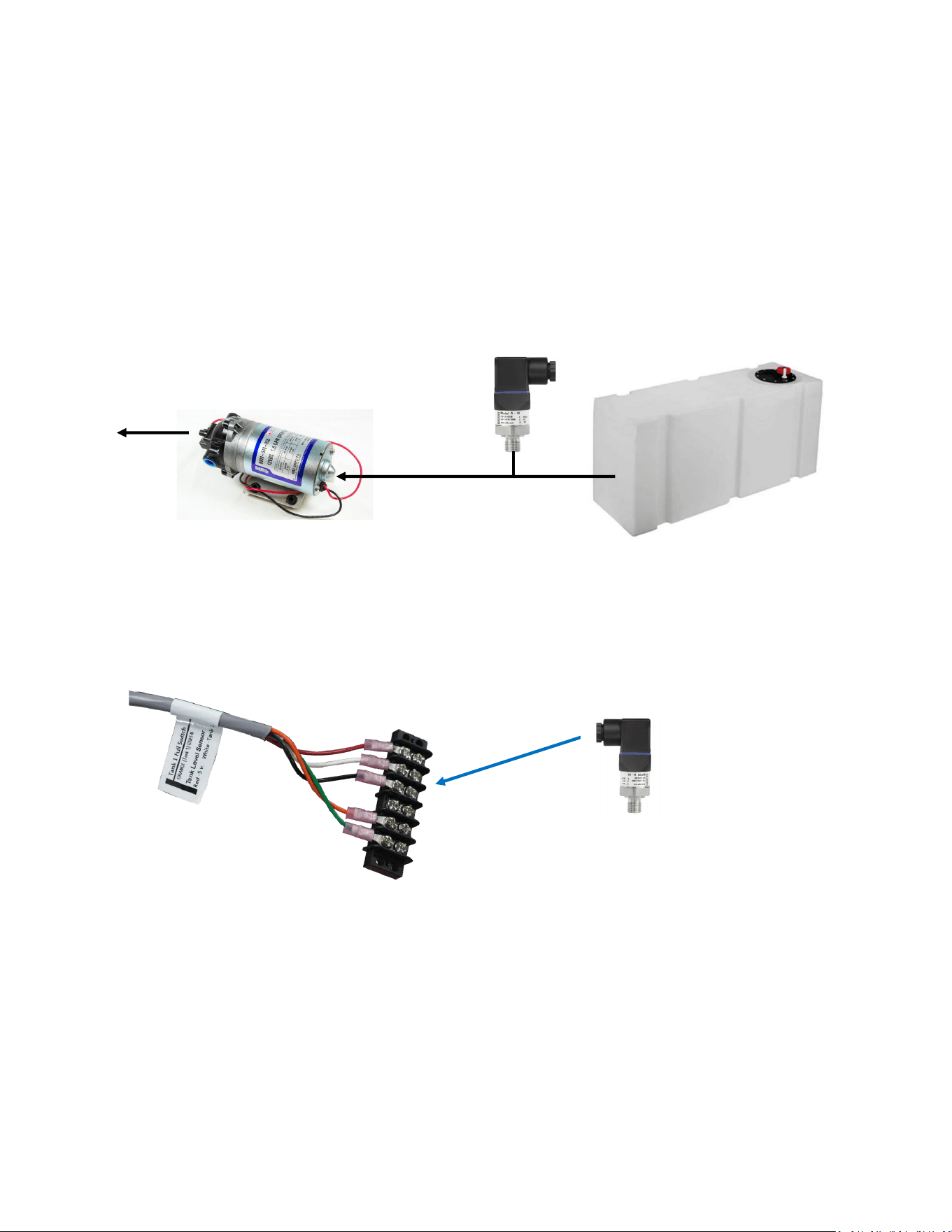
The oponal Tank Level sensor allows even greater control of your ship’s fresh water systems. This
unique level monitoring system requires no holes to be drilled into your tank while measuring tank
volume with greater accuracy than a standard resisve oat.
Turn o the ship’s domesc water system, close the fresh water supply valve at the water tank,
then bleed o the pressure by opening a tap in the galley or head sink.
Install a tee in the water supply hose at the boom of the tank, or at inlet to the domesc water
pump. Connect open leg of the tee to the Tank Level Sensor. Note: The tank level sensor requires
a 1/4” npt connecon. We recommend installing a minimum 1/2” tee, and using a reducing bush-
ing to connect the sensor.
Tank Level
Sensor
Fresh Water
Tank
Domestic
Water Pump
Connect:
Red to Red
White to White
Black to Black
If a 2nd Tank Level Sensor is going to be installed, it should be installed at the
base of the second tank. If monitoring 2 water tanks, they must be isolated
from each other with a valve to read properly.
The wiring connecons for the second Tank Level Sensor are located inside the
Spectra Connect control box. See System Sengs secon of this manual for in-
strucons on enabling the second Tank Level Sensor.
See the Tank Level Calibraon (pg. 28) in the Commissioning secon of this
manual.
Optional Tank Level Sensor Installation
Route the 3 conductor cable back to the Spectra Connect control board at the feed pump
module. Extend the wires as necessary. If you must extend the wires beyond 50’ contact the
factory to ensure proper operaon.
Connect the Tank Level Sensor cables to the 3 conductors label Tank Level Sensors at the feed
pump module. Polarity must be maintained!

31
Operation
32
Commissioning
New System Start-Up and Testing
Use this procedure when starng a new watermaker for the rst me and whenever the
system contains preservave or cleaning chemicals.
Avoid running the system if the vessel is in contaminated water, such as a dirty harbor or
canal. The system should be fully run tested before leaving on an extended journey. It is
preferable to sacrice a prelter by tesng the system briey in turbid water rather than
waing to get oshore to discover a problem or deciency in the installaon. If the locaon or
weather prevents proper tesng refer to the secon Dry Tesng with an Arcial Ocean.
1. First Check That:
• Seacock is open
• Toggle switch on the Feed Pump
Module is in the Run Auto posion
• Domesc fresh water pressure system
is on.
2. Open pressure relief valve 1/2 turn and remove the
Green Tag and washer!
3. Turn on the power to the system and the Spectra Connect screen will display, “Has the
system been stored with chemicals?” Press ‘Yes’, to start the Purge sequence. Note: The
watermaker will shut down if the pressure relief valve is le closed during the Purge mode.
• Alarm will sound
• Display will read “Has the
system been stored with
chemicals?”
• Conrm the Pressure Relief
Valve is open
• Press ‘Yes’ to start the Purge
sequence
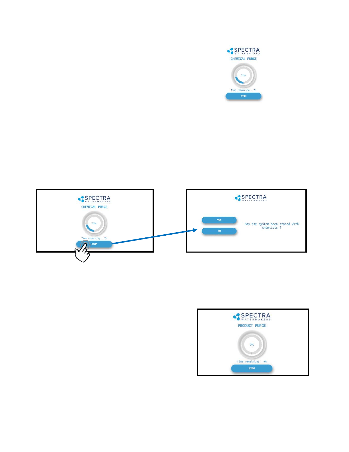
Warning! Damage may occur if the purge sequence is bypassed and
the membrane is pressurized with storage chemical in it.
33
Note: If you must stop the purge sequence for any reason, the control will default back to
the beginning of the purge mode to protect your system.
5. Aer the purge sequence the display will alarm with the message “Close pressure re-
lief valve.” Close the valve and proceed by pressing Ok to resume the Purge Cycle.
If the system is new from the factory, or stored with Propylene Glycol, addional purging me
may be required.
6. The system will now run under pressure and
desalinate water. This mode diverts the product water
overboard in case there is any residual chemicals in
the membrane. Carefully inspect for leaks over the
enre system! Shut down the system and repair any
leaks you nd.
Check the strainer and the brine discharge for water ow. The system should fully prime
within 60-90 seconds and all air should be out of the feed water hoses. The feed pump will
sound smooth.
There should be no bubbles anywhere in the intake hoses. If the feed pump connues to
sound rough, nd the reason before connuing! Inspect the system for leaks.
4. The system will start purging and the display will
show the progress and me remaining
New System Start-Up and Testing - Cont.
7. Aer the Product Purge cycle completes, the system will prompt to Restart, then advance
to the Main Menu. If this is a NEW INSTALLATION, connue to the Calibraon Instruc-
ons to nalize the installaon. If you are pung your watermaker back into service,
your system is now ready for use.
34
Dry Testing with an Artificial Ocean
If it is not possible to test run the system with the boat in the water, you may test the system
with an arcial ocean. You will need 1.3 lbs. of non-iodized salt (rock salt, sea salt, or aquarium
salt) to make a 5 gallons (33 grams of salt per liter) of water that is about 33,000 PPM salinity
(average seawater salinity). Make sure the domesc water system is powered up and the boat’s
tank has at least 60 gallons (230 Liters) of water to purge the storage chemicals from the system.
Conrm that the charcoal lter is installed in the feed pump module, and the domesc water
line is connected.
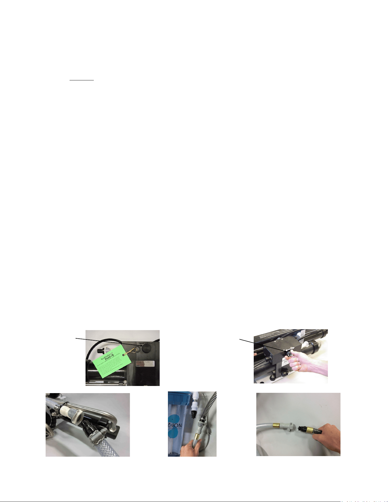
1. Open the pressure relief valve on the Clark Pump. Remove the green tag and spacer.
2. Power up the system. When the Spectra Connect displays “Has the system been stored with
chemicals?”, select “No” to bypass the purge mode.
3. Press the Fresh Water Flush buon to run a full ush cycle. Do this six mes to purge the
storage chemicals, a 36 minute process.
4. Replace the brine overboard hose with the brine service hose per gure 1.
5. Push the Fresh Water Flush buon again to ll the bucket with fresh water from the brine
discharge service hose (hose aached to Clark Pump). Press Stop when the bucket is full.
6. Mix the salt to the proper proporon or use an aquarium hydrometer to adjust the salinity
level to a specic gravity of 1.025.
7. Remove the fresh water ush hose from the fresh water ush module or Z-Ion at the Quick
Connect ng, and connect the intake service hose, per Figure 2. Disconnect the product
tube from the diversion valve, and using another small piece of tube, route it into the bucket.
8. Push the Start buon, then press Auto Run and program the Connect to make 10 gal (38 L)
of water, roughly 40 minutes of operaon.
9. Allow the system to prime and then close the pressure relief valve. The system should build
pressure shortly and start making water, with the brine and product water recombining in
the bucket to be cycled again. This will gradually heat the water. Do not let the water tem-
perature exceed 120 deg. F (49 deg. C).
10. Run the system under pressure, checking for proper operaon and leaks. Aer tesng the
system, re-install the brine discharge hose, product tube, and fresh water hose from the
strainer. You can now ush the system by pressing the Fresh Water Flush buon.
Remove tag
and washer
OPEN PRESSURE
RELIEF VALVE
Fig. 1 Fig. 2 Fig. 3
35
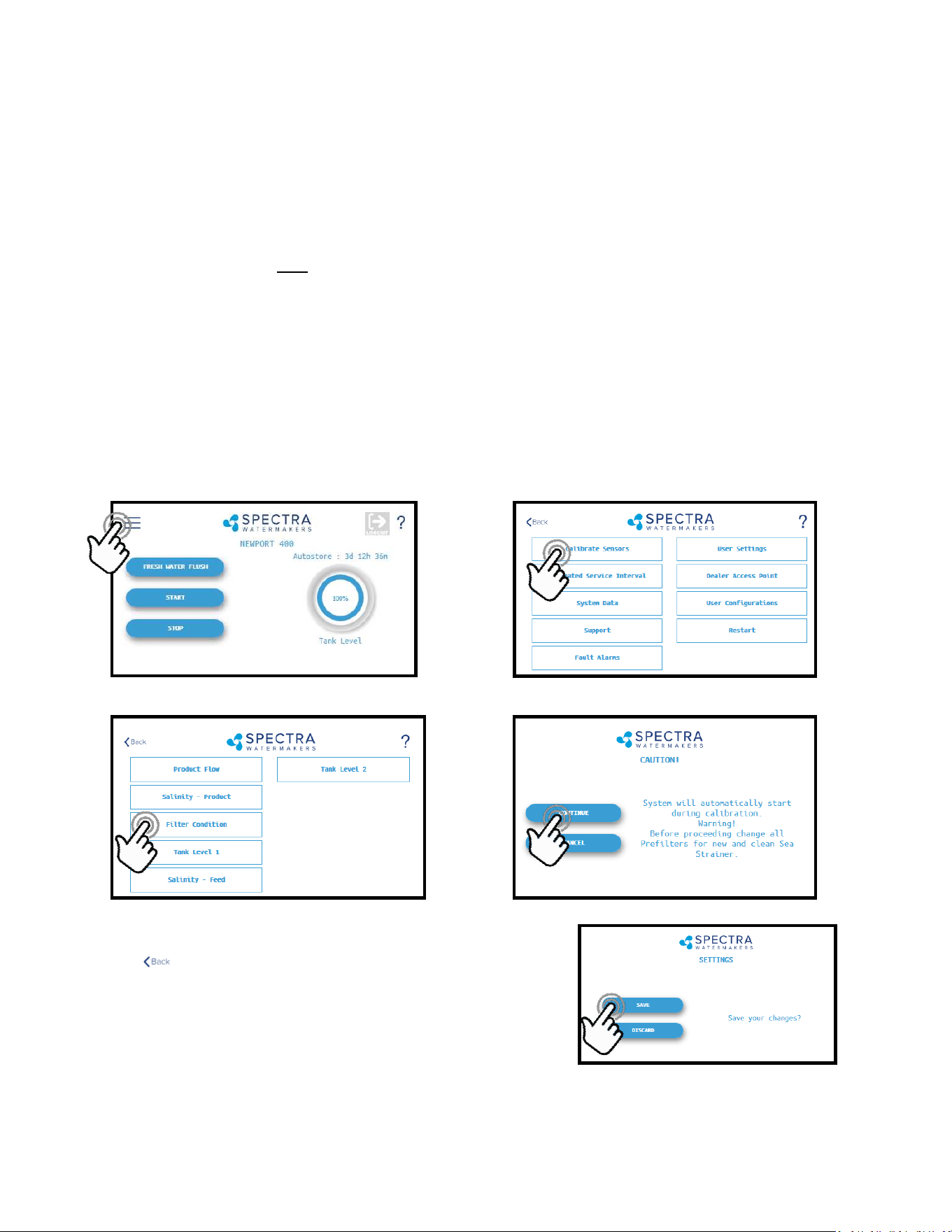
3. When the Calibraon Sequence is complete, press the
buon in the upper le corner to return to the
Main Menu.
When prompted by the display, Click Save to make
sure that the Calibraon is stored in the system
memory.
4. The Filter Condion has now been calibrated to match your installaon.
1. During the calibraon sequence the system will automacally start, begin to make water
for several minutes and then shut itself down. Make sure that the lters have been re-
placed for new, the strainer is clean, and all thru-hulls are open before proceeding.
2. Follow the steps in Figures 1—4 below to iniate the Calibraon Sequence.
Sensor Calibration
Many of the sengs on your system have been pre-calibrated during standard factory tesng,
however, there are a few sengs that will vary based on the installaon, vessel, and other
onboard condions. If the system has just been installed you must calibrate the Prelter
Condion before proceeding.
This procedure does not need to be done with each lter change under normal operaon, it
should ONLY BE DONE IF THE FILTER CONDITION WON’T RESET TO 100% WITH NEW FILTERS
AND A CLEAN/NEW STRAINER SCREEN.
Prefilter Condition Calibration
Fig. 1 Fig. 2
Fig. 3 Fig. 4
36
Adjustments for your Bimini 300 are typically calibrated from the factory to ensure that sea
water is thoroughly ushed out of the watermaker using the least amount of fresh water.
However, due to dierent lengths of hose runs, dierent rates of ow, and dierent pressures
in shipboard fresh water systems, the ush duraon should be opmized for your boat. The
ush cycle is adjusted with 2 sengs: the pump speed and the ush duraon.
Check the pump speed
1. Close the thru-hull for the raw water inlet.
2. Push the Fresh Water Flush buon. The ush valve will open and the feed pump will start
at Flush Speed. If the ush completes normally, then the Flush Cycle is set properly.
3. If the display alarms ‘Service Prelters’ then the fresh water pump is not supplying enough
water, and the feed pump needs to be slowed down.
Slowing down the pump during a Fresh Water Flush
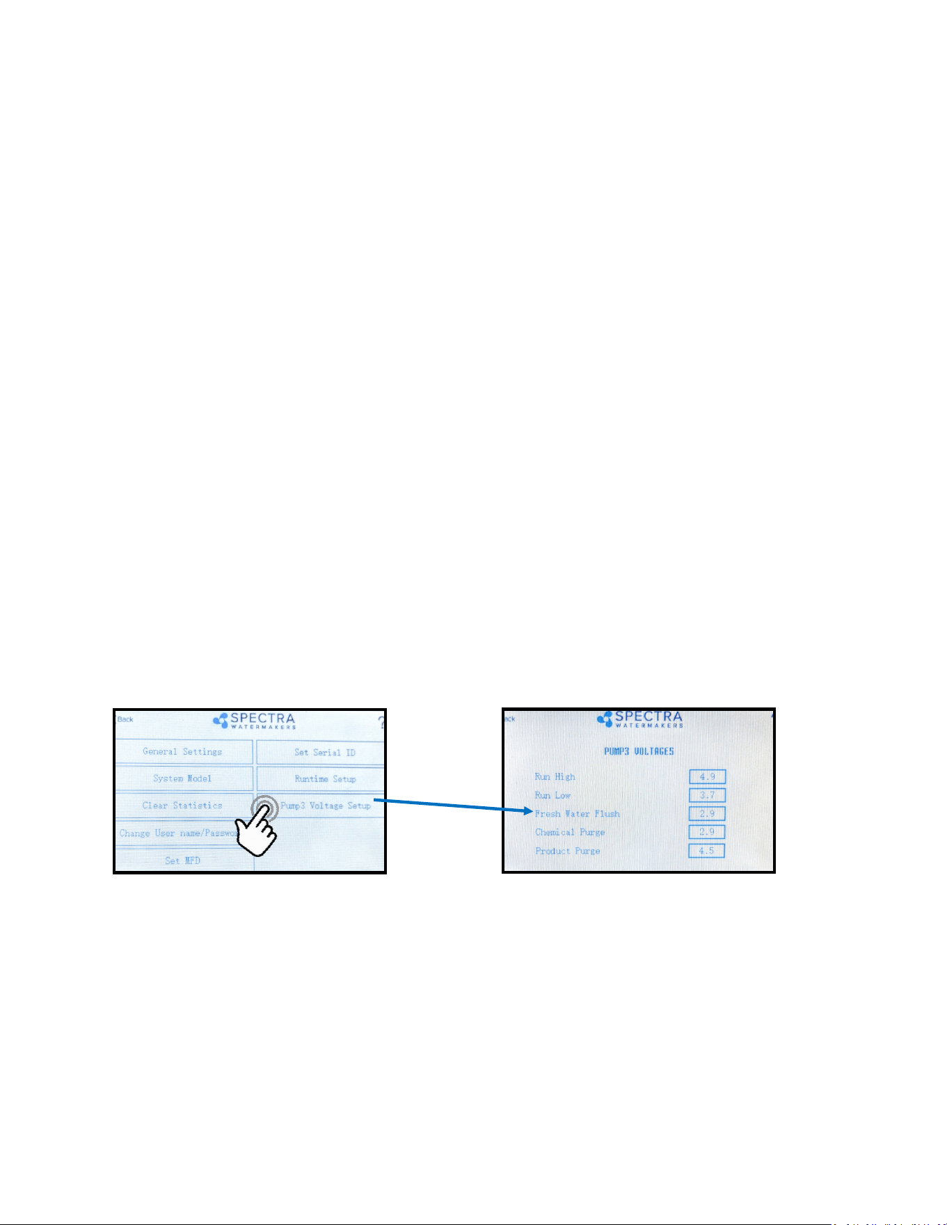
You can slow down the feed pump from the Spectra Connect Display’s Dealer Access Sengs.
Logging into the Dealer Access Sengs is outlined in the Spectra Connect Programming secon
of the manual,
Once in the Dealer Access sengs navigate the screens as follows:
Bring down the Fresh Water Flush down 0.5 (for example from 2.9 to 2.4) and preform another
test. If you sll get the alarm repeat this process unl the Bimini ush speed matches that of
your fresh water system and you no longer are received an alarm.
Once you’ve adjusted the speed correctly, the speed controller will stay programmed for this
speed during fresh water ushes.
Flush Adjustments
Calibration - Cont.
37
3. Check/Adjust the ush duraon
Run the watermaker for 10 minutes to ll the system with seawater, conrm that the diver-
sion valve opens and water is diverted to the tanks.
Press the ‘Stop’ buon. The system will automacally fresh water ush.
Allow the fresh water ush to connue to compleon. At the end of the ush cycle capture
some of the ush water at the brine discharge in a clean cup. Measure the salinity of the brine
discharge and conrm that it is below 1000ppm using a calibrated hand held TDS meter.
If the ush duraon needs to be increased, seek the Spectra Connect programming instruc-
ons in this manual.
Flush Adjustments - Cont.
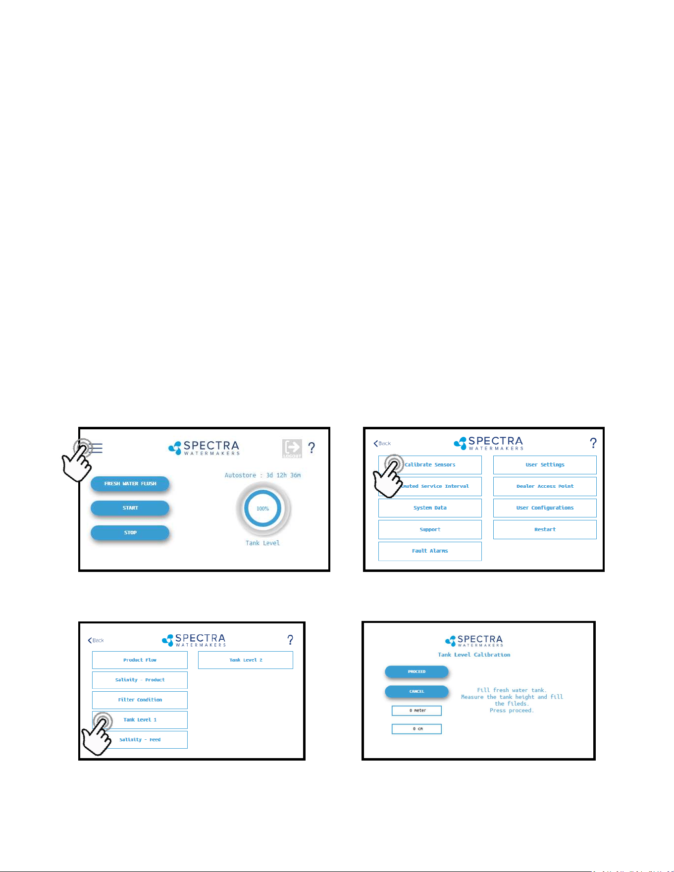
Tank Level Sensor Calibration
Follow the steps in Figures 1-4 laid out below to enter the calibraon sequence for the opon-
al Tank Level Sensor(s).
1. Press the Menu Buon 2. Press the Calibrate Sensors Buon
3. Press the Tank Level 1 buon
4. Fill the fresh water tank to be monitored.
Fig. 1 Fig. 2
Fig. 3 Fig. 4
38
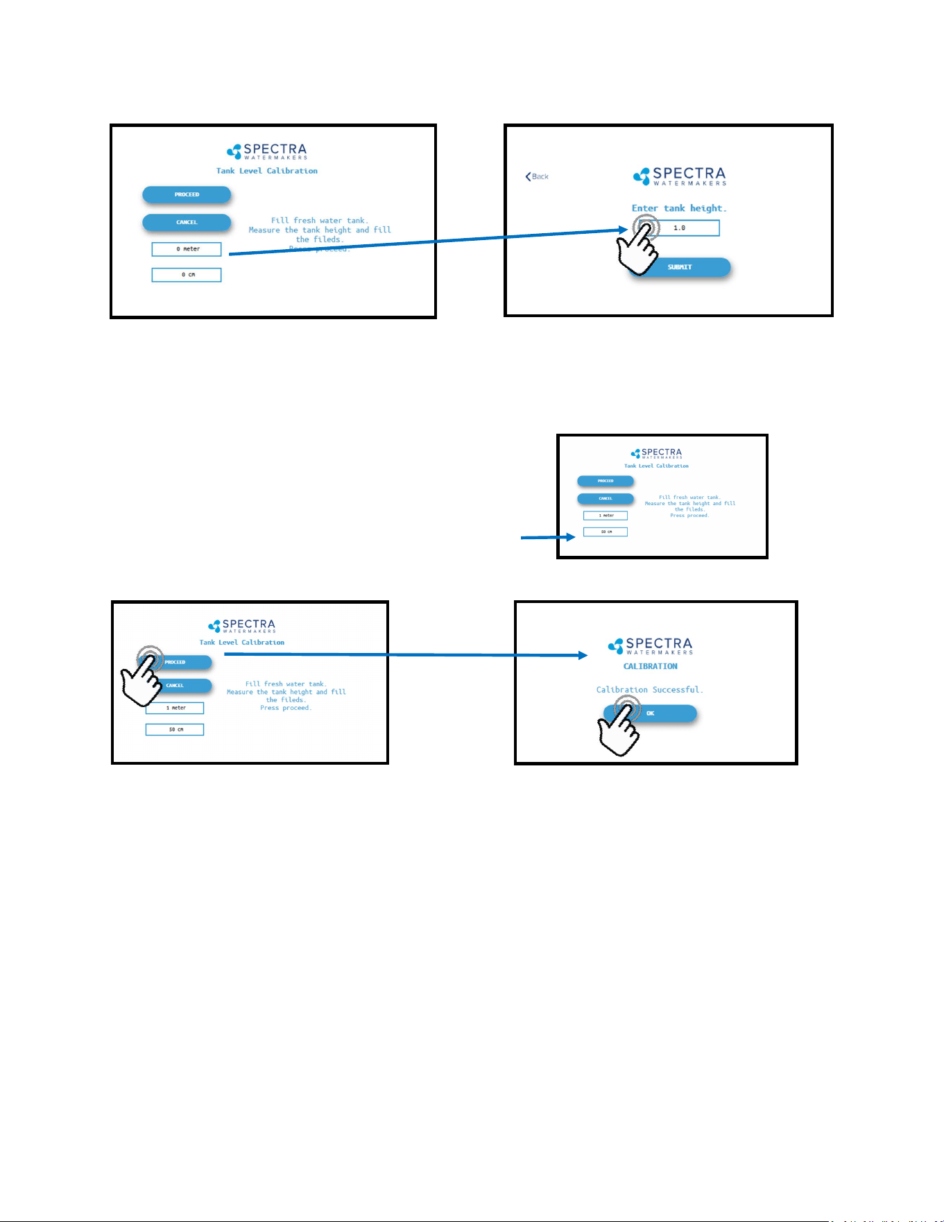
Tank Level Sensor Calibration - Cont.
5. Measure the approximate height of the water tank in feet and inches (or in meters and
cm’s).
6. Press the Feet (Meter) eld to enter the tank height in feet (meters). Press the Inch (cm)
eld to enter the height in inches.
Ex: If the Tank height is 150cm:
Enter ‘1’ in the eld labeled ‘Meter’
Enter ‘50’ in the eld labeled ‘cm’
7. Press ‘Submit’ and conrm your entry matches your measurement.
8. You must save all changes when prompted aer exing the sengs menu.
39
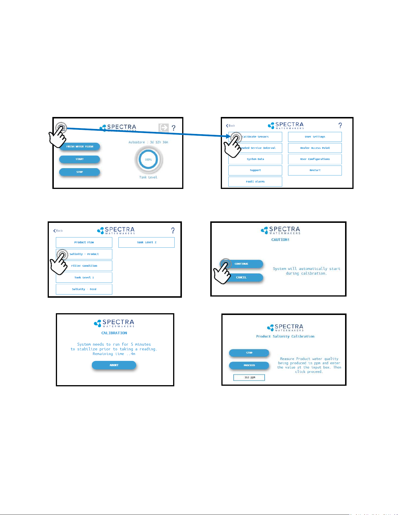
3. Press the Salinity—Product Buon 4. Press Connue to acknowledge the warning
5. The system will run for a minimum of 5 minutes to stabilize the product water salinity.
6. Using a calibrated handheld TDS meter measure the salinity of the product water at a
sampling port, or a convenient locaon if no sampling valve was installed.
7. Touch the ‘PPM’ eld and enter the reading taken above.
8. Press ‘Proceed’ to store the new calibraon value. You must save all changes when
prompted aer exing the sengs menu
Fig. 1 Fig. 2
Fig. 3 Fig. 4
Salinity Calibration
1. Press the Menu Buon 2. Press the Calibrate Sensors Buon
The Salinity probe has been calibrated at the factory during tesng and is not normally
required during commissioning. If the product quality is not reading accurately, follow
calibraon steps.
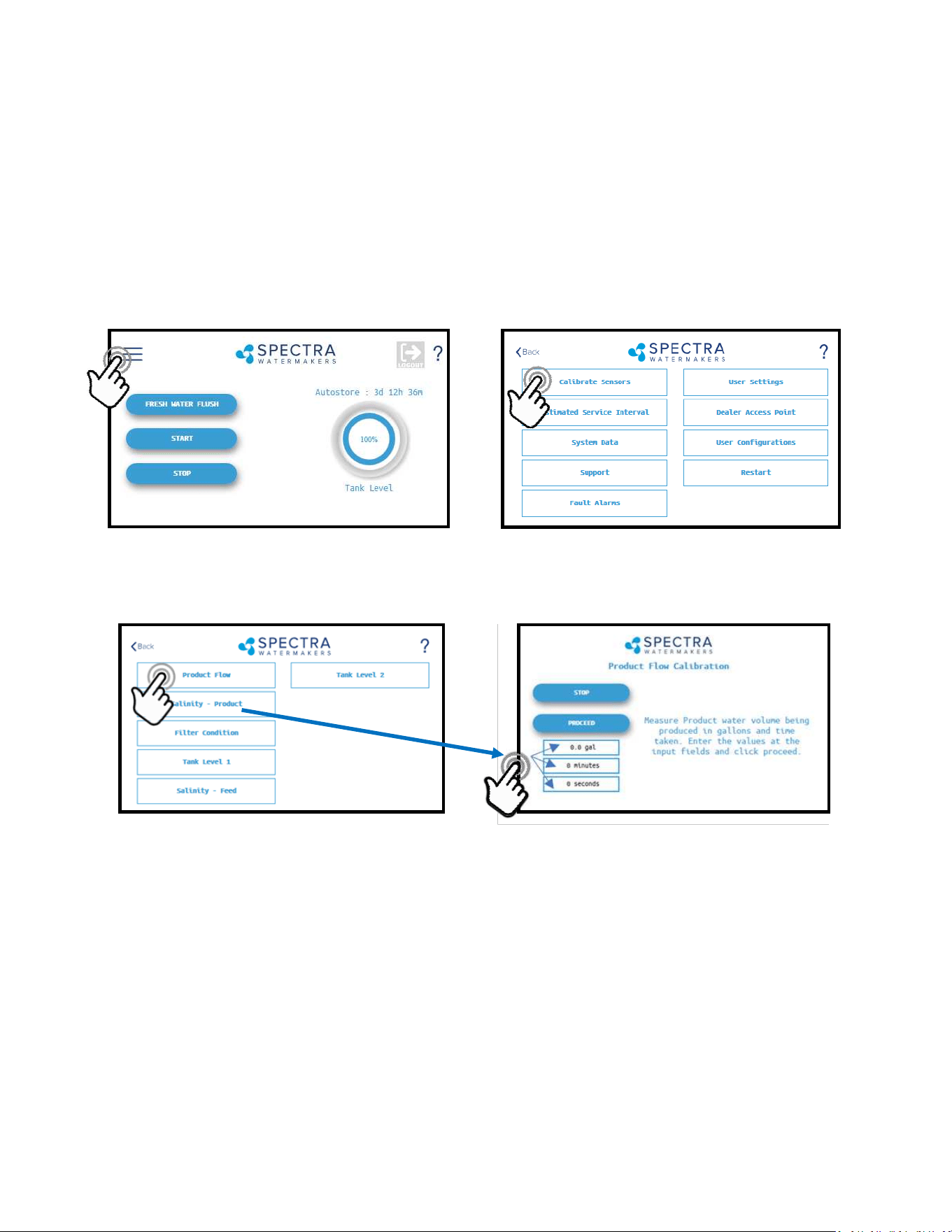
40
4. Once the system has started and a steady stream of water is owing from the product wa-
ter tubing, me in minutes and seconds, how long it takes to ll a container of a known
volume.
5. Touch the ‘Gal’ (’Liter’) eld to enter the volume of the container used.
6. Touch the ‘Minutes’ eld to enter the minutes it took to ll the container. Only enter the
minutes, ex: 3 min 15 sec should be entered as 3.
7. Touch the seconds eld to enter the seconds it took to ll the container. Only enter the
seconds, ex: 3 min 15 sec should be entered as 15.
8. Press ‘Proceed’. You must save all changes when prompted aer exing the sengs menu
3. Press the Product Flow Buon
The Product Flow sensor has been calibrated at the factory during tesng and isn’t normally
required during commissioning. If the product ow is not reading accurately, conrm the
product ow rate by following the Product Flow calibraon steps.
Product Flow Calibration
1. Press the Menu Buon 2. Press the Calibrate Sensors Buon
41
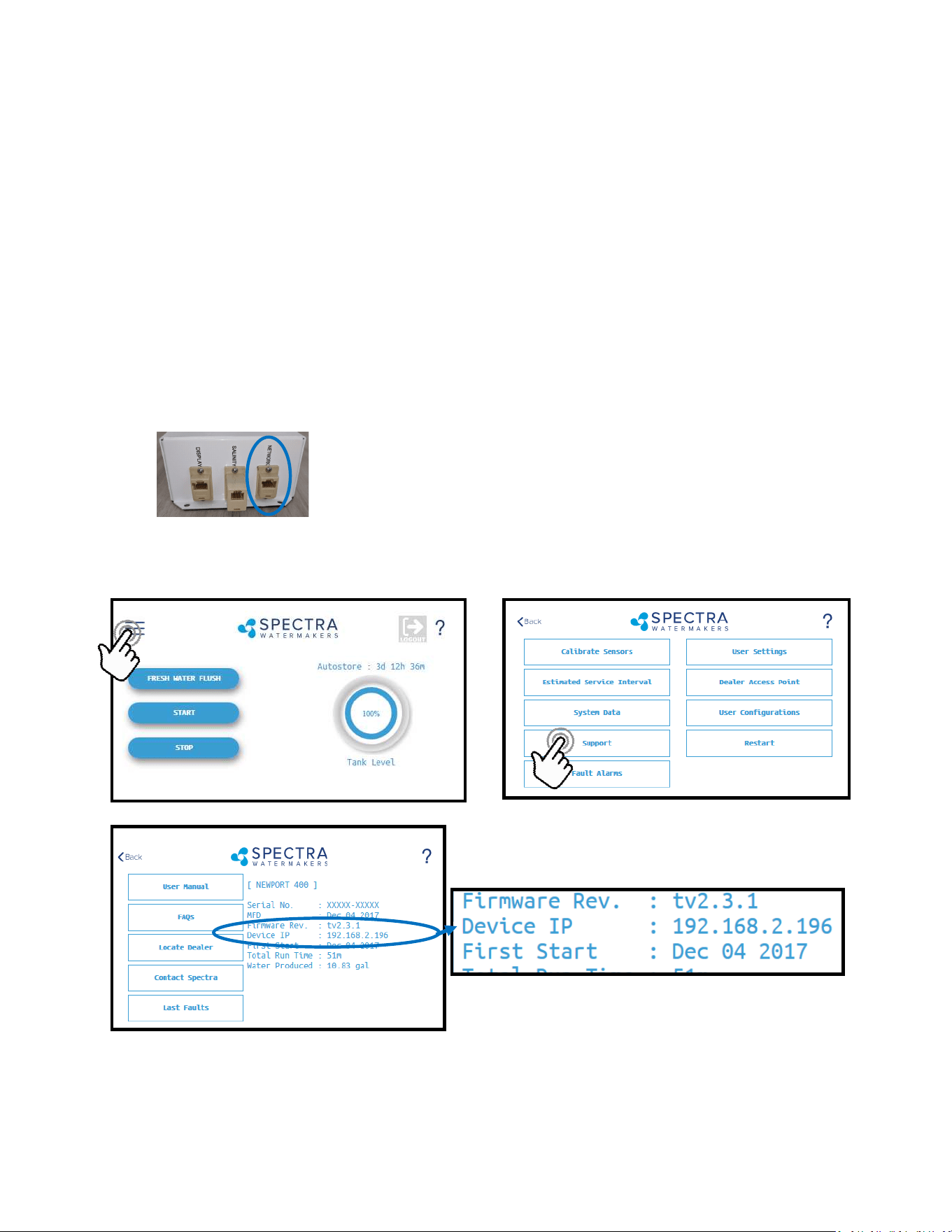
Networking
Your Spectra Connect is equipped with state of the art networking opons to allow the
maximum user control in a wide variety of installaons. The instrucons below will help you
get the most out of your Spectra Connect.
Connecng to the exisng Network
1. Turn power to the system o.
2. Connect a standard Cat5e or Cat6 ethernet cable from jack labeled network to your ship’s
router or networking switch.
3. Turn power to the system back on.
4. Follow the screen prompts below:
Note: If you are connecng direct-
ly into a wireless router, DO NOT
CONNECT TO THE WLAN (Wireless
Local Area Network) ethernet
port. You must connect to one of
the router ports labeled 1, 2, 3, 4,
etc.
5. Note the line ‘Device IP’ shown in Fig. 3 and record the 10 digit numerical address on the
front of this manual.
Fig. 1 Fig. 2
Fig. 3
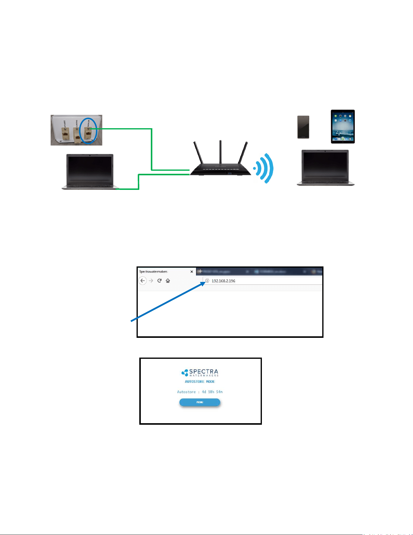
Note: Your Spectra Connect is only available when your device is connected to the same local
network as the Spectra Connect control board. If you have diculty connecng to your
watermaker control applicaon, double check the that your device network is the same as your
Spectra Connect
42
8. Your computer should now show the same image as shown on your local Spectra Connect
7. On the computer, tablet or smartphone, open a web browser such as Firefox, Chrome, or
Safari. In the web address bar at the top, type the ‘Device IP’ address previously recorded.
Press ‘Enter’.
Note: Internet Explorer may not be compable with your Spectra Connect web app. If
formang issues occur, use another browser such as Firefox, Safari, or Chrome.
Ex: Address Bar—Firefox
9. Your web browser is now synced with your Spectra Connect. Any buons you press on
your web browser will be controlling your watermaker.
Cauon! If operang your watermaker from a computer, phone, or tablet, you must keep
the tab open while the system is in operaon and the volume turned up on your device in
order to hear any audible alarm faults.
Connecting To The Existing Network - Cont.
Ship’s Router or Switch
6. Connect your computer, tablet or smart phone to the local network your Spectra Connect
is plugged into.
Wired Connecon: simply plug your computer’s ethernet port directly into the router
or switch where you connected the watermaker.
Wireless Connecon: make sure your device is connected to the same local wireless
network as the Spectra Connect
Wired Connecon
Wireless Connecons
43
If the system has been pickled or stored with chemicals, use the New System Startup
procedure on page 32.
Your watermaker will fresh water ush aer every use. Remember that you need to run the
system approximately half an hour to make enough fresh water for one ush.
You may noce that the system output is higher when charging your baeries. This is normal.
1. Check to see that the inlet and brine discharge seacocks are open and the domesc
pressurized water system is turned on.
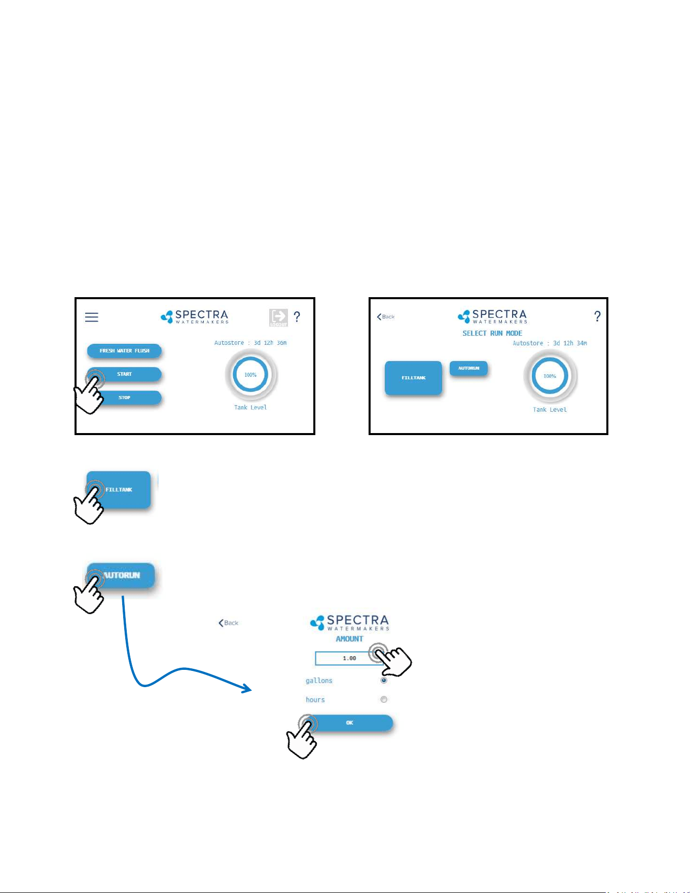
2. Press the ‘Start’ buon, then select the desired operang mode.
Runs your watermaker unl the Tank Full switch closes, fresh water ushes the
system, then goes into ‘Auto Store’ mode and the Flush Interval mer starts.
This is the default mode of operaon.
Gives you the opon to run for a preset amount of me, or a preset volume of
water to be produced. If no tank switches are installed, and they have been
disabled in the system sengs, this is the only Operang Mode available.
Normal Operation
Standard Operating Modes
Enter Volume or Time desired
Select Gallons/Liters or Hours
Starts the
Watermaker
44
3. The system will now begin the start sequence. Pressing ‘Stop’ will bring you back to the
Main Menu.
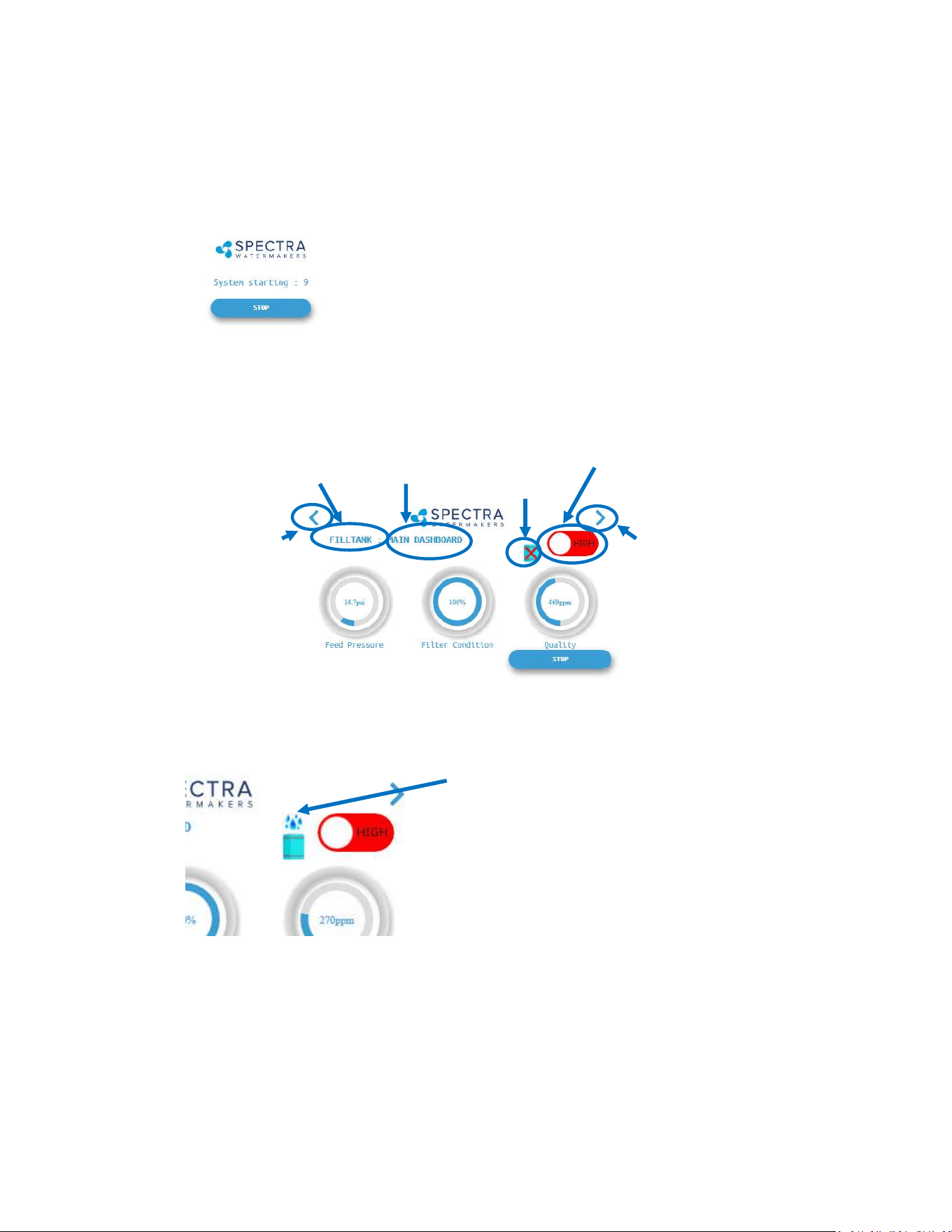
4. Once the Boost Pressure reaches the minimum threshold, the system starts operang and
you will be taken directly to the Main Dashboard.
Page
Le
Page
Right
Run Mode
(High)
Operang
Mode
Current
Screen
Diversion
Valve Status
(CLOSED)
Diversion
Valve Status
(OPEN)
6. When the Product Water Quality is below the programmed threshold, the Diversion Valve
opens, allowing water to enter the tanks and the screen image changes.
7. Pressing the < (Page Le) or > (Page Right) arrows will show a dierent screen with dier-
ent operang informaon for your watermaker.
Verify that the system is operang according to the factory specicaons detailed on p.36.
See the Troubleshoong secon to idenfy any anomalies.
Normal Operation - Cont.
45
To access this informaon about your watermaker while it is running press the < or > buons
to scroll through the pages.
Nominal Operating Parameters
8. When the Run Cycle completes, or by pressing ’Stop’, the system will start to Fresh Water
Flush. You MUST FRESH WATER FLUSH the watermaker AFTER EACH USE, or serious damage
can occur
8. Aer Fresh Water Flushing the system will enter the ‘Auto Store’ mode, and the interval
mer unl the next scheduled ush will show on the screen.
Normal Operation - Cont.
System
AMPS Feed Pressure Stac * Total Flow/Feed Flow Product Flow
12V
MAX 24V MAX PSI bar PSI GPM LPM
GPM
(min)
LPM
(min)
GPH LPH
GPH
(min)
LPH
(min)
Bimini 300 HI 19.5 21.5 9.75 10.75 80-90 5.6-6.3 25-30 2.4 9.1 2.3 8.7 12.5 47.3 12 45.4
Bimini 300 LO 14 16 6.75 7.75 65-75 4.5-5.2 25-30 1.7 6.4 1.6 6.0 9 34.0 8 30.2
For Spec Producon:
12V Systems: Run at 13.2 VDC min
24V Systems run at 26.4 VDC min

46
Other Operating Modes
Run Low Mode
You can toggle back and forth between Run
High Mode and Run Low Mode by tapping the
‘High’ toggle buon.
Run Low Mode may be selected to reduce
power consumpon or to lower the feed pres-
sure.
Note: The system will automacally drop to Low Mode when it senses high feed pressure, or
dirty prelters.
Normal Operation - Cont.
Auto Fill Mode
If your vessel is equipped with a Tank Low and a Tank Full switch, and both are enabled in the
system sengs, then your Start Menu will allow the system to be operated in Auto Fill mode.
WARNING: NEVER RUN YOUR WATERMAKER UNATTENDED. EQUIMENT CAN BE SERIOUSLY
DAMAGED, AND IT IS POSSIBLE TO SINK THE VESSEL! Use extreme cauon when operang in
Auto Fill mode!
In Auto Fill Mode the Spectra Connect will automacally ll your water tank, stop itself, fresh
water ush, return to Auto Store mode with the ush interval mer running, and then turn
itself on again to ll the tank as soon as the water level drops below the Tank Low Switch with
no addional user commands.
Addionally, if power is interrupted at any stage of operaon, the Spectra Connect will return
to Auto Fill mode, ensuring that your tanks will always have water.
47
Warning! Proper understanding of the Spectra ush system and the vessel’s fresh water system is
mandatory for extended use of Auto Store. The ush cycles must not be allowed to drain all the
fresh water from the tank or damage to the vessel’s systems and the watermaker may occur.
The Auto Store funcon ushes the watermaker at programmed intervals. As long as the
watermaker is ushed with fresh water every 5 days (30 days with the Z-Ion) you need not store
the system with chemicals.
• Make sure there is enough water in the fresh water tanks to supply the watermaker for more
than the expected me of operaon in the Auto Store mode. If there isn't enough fresh water
in your tank, seawater will be drawn in and the system will not be ushed with fresh water.
The Bimini 300 requires about 7 gallons (26 liters) for each ush. The boat’s pressure water
supply must be on and stay on while the system is in Auto Store mode. If these condions
cannot be met, then pickling with SC-1 storage chemical or propylene glycol is preferable.
• Make sure the pressure relief valve on the Clark Pump is closed.
• The system must be connually powered on during the Auto Store mode. Turning o the
power will disable the automac fresh water ush and damage may occur.
Auto Store
Flushes the system with fresh water, then
acvates the ush interval mer:
Normal Operation - Cont.

48

49
Maintenance, Storage, &
Troubleshooting

50
Maintenance
General
Periodically inspect the entire system for leakage and chafing. Repair any leaks as soon as you
find them. Some crystal formation around the Clark Pump blocks is normal. Wipe down any salt
encrusted areas with a damp cloth.
Watermakers are at their best when run regularly. Biological fouling in the membrane is more
likely when a watermaker sits idle. A warm environment will cause more growth than a cold en-
vironment. A fresh water flush every five days (30 days with the Z-Ion) will greatly reduce biolog-
ical growth, but may not stop it completely. The Z-Ion system protects the membrane from bio-
fouling without the use of storage chemicals.
The Seawater Strainer
The seawater strainer’s stainless steel element should be inspected, removed, and cleaned as
needed. Ensure that the thru-hull is closed before disassembly and the gasket is in place before
reassembly. When the system is put into storage, remove the strainer, rinse with fresh water,
and reassemble dry to impede corrosion. Check frequently during operation.
The Prefilters
Service the prelters as soon as possible aer the prelter condion graph begins to rise. If the
lter condion graph gets all the way to “Replace” the machine will slow down. When display
reaches “Replace” a second me, the alarm will sound and the system will shut down to prevent
damage.
To service the lters close the thru-hull, open the housings, remove the old lters, clean out the
housing bowls, and reassemble the housings with new 20 and 5 micron lter elements. The 5
micron lter goes downstream from the 20 micron. Leave dry unl next startup.
Use only Spectra-approved lters or you may void your warranty. Occasionally, lightly lubricate
the O-rings with silicone grease.
Oil/Water Separator (Optional)
To install oil water separator capability, add a second lter housing UPSTREAM of the 20 and 5
micron housings. Service as you would per the instrucons above.
The Charcoal Fresh Water Flush Filter
Replace the charcoal filter element at least every 6 months. This filter protects the membrane by
removing chlorine from the flush water. Use only a Spectra-approved replacement.
51
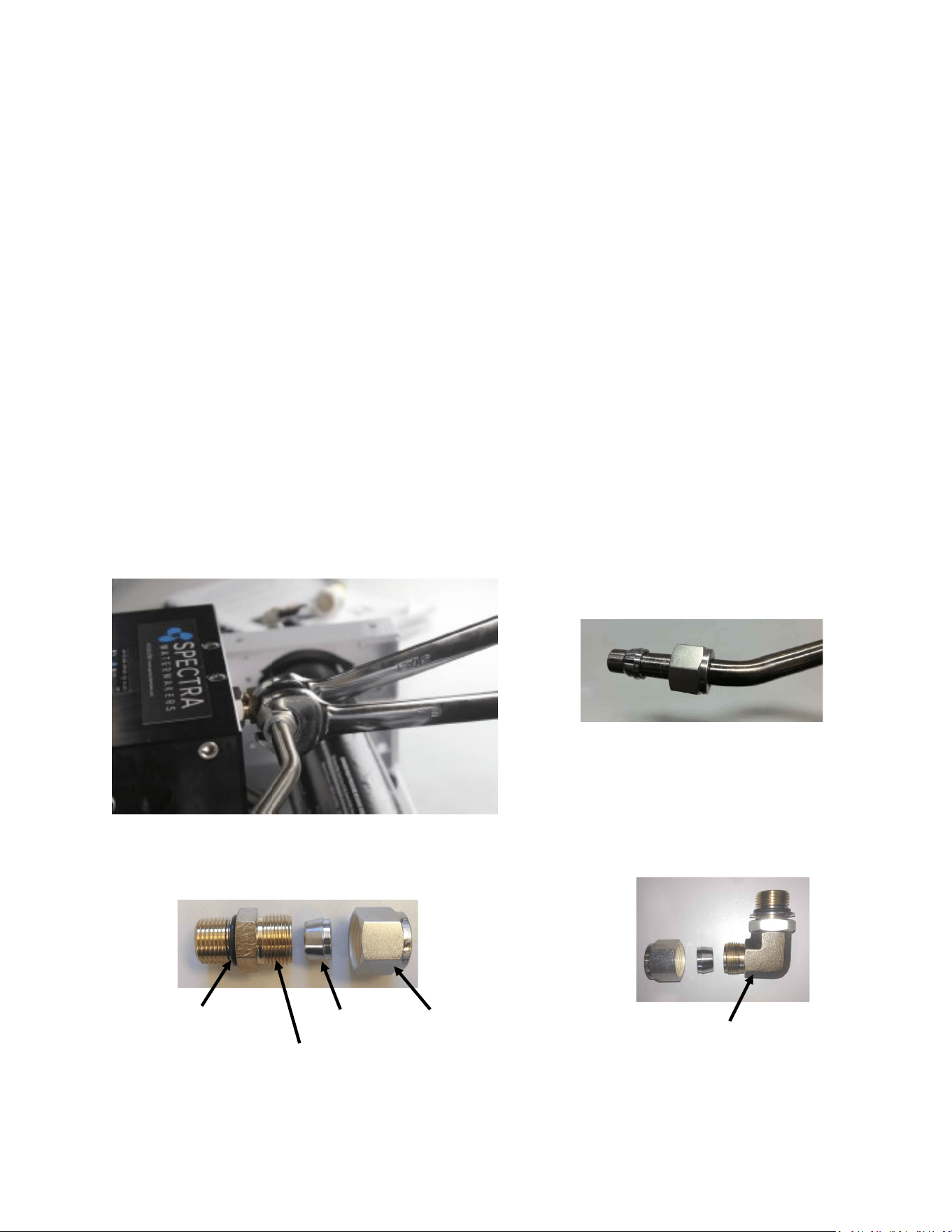
Leaking Fittings
The system has eight high pressure ngs, two on each cylinder on the Clark Pump, two on
the pressure vessel end caps, and two 90-degree elbows on the back of the Clark Pump. As the
compression ng is ghtened, it compresses a ferrule onto the stainless tubing, xing the
ferrule permanently to the tube and holding the compression nut capve.
The body of the ng seals to the underlying component with an O-ring. On the Clark Pump
cylinders and the end caps this O-ring is compressed by ghtening the enre ng. The O-
rings on the 90-degree ngs on the back of the Clark Pump have capve nuts and washers,
which compress the O-rings without turning the enre ng.
If a tube ng leaks it can somemes be resealed by just ghtening. You must use two
wrenches, a 13/16-inch wrench to hold the base, and a 7/8-inch wrench to turn the compres-
sion nut. The 13/16-inch wrench will need to be thin so as not to interfere with the compres-
sion nut. If this doesn’t work, disassemble the ng, grease liberally with silicone grease (the
ferrule and the threads) and re-ghten rmly.
The base O-rings should be gently compressed to achieve a good seal, and may be damaged
by overghtening.
Stainless Fitting Hex Nut
Connector O-RING
Nickel-Bronze High Pressure Elbow
Nickel-Bronze High Pressure Straight Fitting
Ferrule
Maintenance - Cont.

52
The Feed Pump and Clark Pump
The feed pump and the Clark Pump require no routine maintenance except inspection for
leaks. Tighten any hose clamps or fittings that show signs of leakage. The high pressure fittings
threaded into the Clark Pump have O-ring seals with a straight thread. These should never leak
and should never be over-tightened. If one of the tube nuts starts to leak, it can be un-
threaded, sealed with a bit of silicone grease or oil, and tightened with two wrenches very
tightly.
The Membrane
Membranes are susceptible to mineral scaling, biofouling and oxidation damage. The leading
cause of fouling is biological growth that forms when the system is left unused without flush-
ing or pickling. Fouling from mineral scaling can happen under certain seawater conditions, or
from rust. Oxidation damage can occur if the membrane comes into contact with any strong
oxidant, such as Ozone, Chlorine, etc. Monitor the product salinity and feed pressure for high-
er than normal readings, take environmental conditions into consideration.
Note that:
• Cold feed water or a higher salinity seawater source can cause high pressure.
• Low product flow is usually due to low voltage, a worn feed pump, or worn Clark Pump.
Due to the unique design of your Spectra system, low product water volume is typically not a
membrane problem, but frequently related to low voltage, a worn feed pump head, or a worn
Clark Pump. Always perform a flow test before cleaning your membrane.
Test to see if biological growth has occurred: Before running the system, remove the prel-
ters and examine their condion. If the lter housings are full of smelly, discolored water, the
system was not properly stored. Install clean prelters.
Next check the membrane. Detach the brine discharge hose, aach the brine service hose, and
lead it to a bucket. Open the pressure relief valve 1/2 turn, and manually run the system for 30
seconds (metal toggle switch on feed pump module). Examine the brine water: If it is discol-
ored and smells bad, perform an SC-2 cleaning with unchlorinated water before running the
system pressurized. If the brine is fairly clean, follow the New System Startup procedure on
page 32 and run normally. Check for performance. Clean the membranes only if performance
is reduced.
See the Cleaning Procedure for complete instructions.
Maintenance - Cont.

53
Introducon to Spectra Chemicals
We use four types of chemicals: SC-1, SC-2, SC-3, and propylene glycol anfreeze. SC-1 and
propylene glycol are for system storage, while SC-2 and SC-3 are for membrane cleaning. Do
not use sodium-bisulfate, citric acid, or any other storage chemical not supplied by Spectra.
These chemicals, used to store other watermaker brands, will damage the Clark Pump, mem-
brane end plugs, manifolds, and other components. Using non-Spectra chemicals will void
the warranty.
Note: Never use any chemicals with the system pressurized! Always open the pressure relief
valve 1/2 turn. Always follow the instrucons for purging the chemicals as shown in the New
System Startup secon of your owner’s manual.
Storage
SC-1 prevents biological growth when your system is idle. It should not be used as a cleaning
chemical, nor will it protect your system from freezing. A jar of SC-1 is mixed with 1 to 2 gal-
lons of product or dechlorinated fresh water in a bucket and circulated through the system for
10 minutes. This treatment will protect the system for six months, aer which the SC-1 treat-
ment must be repeated. To use SC-1, follow the instrucons for Storage Procedure.
Spectra systems should be stored with propylene glycol if freezing is likely to occur. Propylene
glycol can be used instead of Spectra SC-1 storage chemical for storage in any climate, and
treatment is eecve for one year. Propylene glycol is a food-grade anfreeze used to winter-
ize RV’s, boats, and cabins. Do not use ethylene glycol automove anfreeze, which is toxic
and will damage the system.
The propylene glycol formulaons sold in marine and RV stores are usually diluted with water.
The water remaining in the watermaker before the storage procedure will further dilute the
anfreeze, reducing the microbial protecon and increasing the temperature at which the mix-
ture will freeze.
Anfreeze labeled “Minus Fiy” is a 25% soluon and will begin to form an icy slush at about
+15Degrees F (-10C) and will only provide burst protecon to about Zero F (-18C). Aer a fur-
ther 50% percent diluon by water remaining in the watermaker, “Minus Fiy” anfreeze will
only protect from bursng down to about +25F (-4C). Therefore if low temperature freezing
protecon is required a 60% or stronger anfreeze should be used. 60% soluons are labeled
“Minus 100” and will provide burst protecon to -15F (-27C) even aer a y percent diluon
with residual water. “Minus 200” formulaons are pure propylene glycol.
Maintenance - Cont.

54
Introducon to Spectra Chemicals - Cont.
Complete microbial protecon requires a 25% soluon of propylene glycol, so care must be
taken that the soluon remaining in the watermaker during long term storage is at least 25%,
even if freeze protecon is not required. For these reasons Spectra recommends that all pick-
ling be carried out with a 60% or greater concentraon.
See Winterizing with Propylene Glycol.
Propylene glycol can be dicult to ush from a membrane, especially aer extended storage
periods. This results in high salinity water (high PPM) and residual avor in the product water.
We recommend ushing the system WITH THE PRESSURE RELIEF VALVE OPEN for 4-6 hours
aer storage with propylene glycol—the longer the beer. If, aer extended ushing, you sll
experience low product water quality, cleaning with SC-2 usually removes all traces of propyl-
ene glycol and returns the salinity to the level it was before storage with propylene glycol. See
the Membrane Cleaning Procedure.
Cleaners
Avoid unnecessary cleaning, and avoid cleaning as a diagnosc tool.
SC-2 is an alkaline cleaner used to remove light oil, grime and biological growth. It is most
eecve if heated to 120 deg. F (49 deg. C). In most cases the water quality will increase in
PPM (salinity) aer an SC-2 cleaning. Aer a few hours it should recover to near the level it
produced before the cleaning.
SC-3 is an acid cleaner used to remove mineral and scale deposits. In most cases this is used
rst and if there is no improvement, go on to the SC-2 cleaning. SC-3 will in most cases lower
the product PPM and overall pressures. Scaling is a slow process that may take several months
or years.
For cleaning with either SC-2 or SC-3, see Membrane Cleaning Procedure.
Maintenance - Cont.
55
Storage Procedure
1. Close the intake seacock.
2. Push the Fresh Water Flush buon to fresh water ush the system. Perform a second fresh
water ush in the same way.
3. Remove the quick disconnect ng from the brine discharge outlet of the Clark Pump, per
photo below, and replace it with the quick disconnect brine discharge service hose. Lead the
brine service hose into the bucket.
4. Push the Auto Store buon and run the feed pump unl you have one gallon of fresh water
in the bucket from the brine discharge service hose, then press Stop.
5. Mix 1 container of SC-1 storage compound with the water in the bucket.
6. Remove the hose from the “to strainer” pigtail on the feed pump module and install the inlet
service hose from the service kit, per photos below. Lead this hose into the 5 gallon (20 liter)
bucket as well.
7. Make sure the pressure relief valve on the Clark Pump is
OPEN (un-pressurized) by turning 1/2 turn
counterclockwise
8. Turn on the feed pump by moving the manual control
switch on the control box to ‘SERVICE’. The soluon will be
drawn from the bucket with the service hose, and
returned to the bucket from the brine discharge service
hose. Circulate the storage chemical in the system for
approximately 20 minutes. Stop the feed pump by moving
the switch back to the ‘RUN AUTO’ posion.
Clean Up
Remove the brine discharge service hose from the Clark Pump, and replace the brine discharge
hose that leads to the thru-hull. You may now pump the bucket dry by moving the manual
control switch on the Control Box back to ‘SERVICE’. Stop the feed pump by moving the switch
back to RUN AUTO.
Remove the inlet service hose and reaach the hose from the sea strainer to the “To Strainer”
pigtail on the manifold at the Feed Pump Module. Drain and clean the strainer and any lters in
the system. Reassemble dry. Leave the pressure relief valve open, since the next me you run
the system you will need to purge the storage chemicals with the system unpressurized. Turn o
the power to the system.
Connecng brine discharge
service hose
Aaching intake service hose to
the hose connecng to the sea
strainer.
Removing hose to sea strainer
from the “to strainer” pigtail.
56
Winterizing with Propylene Glycol
See descripon of propylene glycol formulaons, and purging from system, on page 53.
1. Close the intake seacock.
2. Push the Fresh Water Flush buon to fresh water ush the system. Perform a second fresh
water ush in the same way.
3. Remove the hose from the “To Strainer” pigtail, install the inlet service hose from the service
kit, and lead the hose to the boom of a bucket. Connect the brine service hose, and run it
into a second container.
4. Pour 1 gallon (4 liters) of propylene glycol of appropriate
concentraon (see page 46) into the bucket with the intake
service hose.
5. Make sure the pressure relief valve on the Clark Pump is
OPEN 1/2 turn (un-pressurized).
6. Run the feed pump by switching the manual switch on the
control box to ‘SERVICE’ unl about a gallon of water has
owed from the brine discharge service hose, or anfreeze
appears. Propylene glycol will look slightly dierent, and
feel more slippery, than water. Stop the pump by moving
the switch back to ‘RUN AUTO’. Add more propylene glycol to the intake bucket if necessary.
7. Lead the brine discharge service hose into the intake bucket of propylene glycol. Move the
switch back to ‘SERVICE’. The service hose will now draw propylene glycol soluon from the
bucket, and the brine discharge service hose will return it. Run the feed pump and circulate
the propylene glycol for 20 minutes.
8. Stop the feed pump by switching the toggle switch back to ‘RUN AUTO’. Drain the seawater
strainer, the hose leading to the boost pump module, and the hose between the boost pump
module and the feed pump module. Disconnect the product tubing from the membrane hous-
ing and blow residual water out of the tubing. Empty the charcoal lter housing and ush wa-
ter lines. Leave the pressure relief valve open, since the next me you run the system you will
need to purge the system unpressurized.
Your watermaker is now protected from freezing and biological growth and freezing for one year.
Connecng brine discharge
service hose
Removing hose to sea strainer
from the “to strainer” pigtail.
Aaching intake service hose to
hose to sea strainer.
57
Membrane Cleaning Procedure
Spectra cleaning compound (SC-2 or SC-3) must be mixed with fresh water at a rao of 1 container of
compound to 3 gallons (12L) of unchlorinated water. A Bimini 300 system requires one container of com-
pound per cleaning.
1. Close the intake seacock.
2. Push the Fresh Water Flush buon to fresh water ush the system. Perform a second fresh
water ush in the same way.
3. Remove the quick disconnect ng from the brine discharge outlet of the Clark Pump, and re-
place it with the quick disconnect brine discharge service hose. Lead it into a 5 gallon (20 liter)
bucket. Push the Fresh Water Flush buon and run the feed pump unl one gallon of fresh wa-
ter runs into the bucket from the brine discharge service hose. Press Stop.
4. Remove the hose from the “To Strainer” pigtail and install
the inlet service hose from the service kit. Lead both hoses
into the bucket.
5. Make sure that the pressure relief valve on the Clark Pump
is open (un-pressurized).
6. Mix the cleaning chemical in the bucket. If possible, heat the
soluon to 120 F (49 C).
7. Move manual switch on the Feed Pump Module to SERVICE
SYSTEM. The intake service hose will draw soluon from the
bucket and the brine discharge service hose will return it.
Circulate the soluon through the system in this manner for 45 minutes. Stop the pump by
moving the toggle switch back to ‘RUN AUTO’.
8. If the soluon cannot be heated, allow the soluon to sit overnight before proceeding to the
next step.
9. Replace the brine discharge overboard hose and run the pump unl the bucket is empty by
moving the manual switch to ‘SERVICE’. Return the switch to ‘RUN AUTO’.
10. Follow the New System Startup procedures to ush the chemicals out of the system (DO NOT
CLOSE the pressure relief valve!)
11. The system may now be restarted, ushed, or stored.
Connecng brine discharge ser-
vice hose
Removing hose to sea strainer
from the “to strainer” pigtail.
Aaching intake service hose to
the hose connecng to the sea
strainer.

58
Suggested Spares for the Bimini 300
Short term cruising, weekends etc.
A basic cruise kit A. This kit consists of six 5 micron lters and two packs of SC-1 storage
chemical.
Cruising 2 to 6 months at a me.
Two basic cruise kits, one replacement charcoal lter, and one replacement feed pump
head.
Longer than 6 months
Addional lters, oshore cruising kit consisng of Clark Pump seals, O-rings, tools and
membrane cleaning chemicals. One replacement strainer screen, replacement O-ring for
strainer screen, and replacement O-rings for the lter housings.
Common Parts:
Item Part Number
SC-1 STORAGE CHEMICAL KIT-CHEM-SC1
SC-2 CLEANER KIT-CHEM-SC2
SC-3 CLEANER KIT-CHEM-SC3
BASIC CRUISE KIT A KIT-BCK-A
OFFSHORE REBUILD KIT KIT-OFFSH
5 MICRON FILTER FT-FTC-5
CHARCOAL FILTER FT-FTC-CC
6” STRAINER SCREEN FT-STN-6S
OIL/WATER FILTER FT-FTC-OW
FEED PUMP HEAD KIT-PMP-140MAG
6” STRAINER O-RING SO-STN-6SS
FILTER HOUSING O-RING SO-FHS-10H
SALINITY PROBE EL-MPC-SP4
CHARCOAL FILTER HOUSING O-RING SO-FHS-3PCS10

59
Feed pump runs constant-
ly, will not turn o
• Turn o manual switch on feed
pump module
• Manual switch in on or
service posion
Display acvates, but pump
will not run
• Loose or broken pump
wire connecon
• Tanks are full (if equipped
with tank switch)
• Check wiring at terminal block
inside Connect Controller Box
• Check tanks– system cannot
be started if tanks are full.
System runs, no product
water delivered to water
tanks, GPH bar graph shows
OK, red X is displayed over
tanks.
• High salinity of product
water, causing system to
reject water
• Salinity probe out of cali-
braon or defecve, bad
cable
• Chlorine damage to mem-
branes
• Pressure relief valve open
• Check for low feed pressure
• Check for leaks at high pressure
hoses
• Test product water with hand-held
tester– if over 500 PPM for 1 hour,
contact factory
• Close pressure relief valve
No lights or display, system
does not operate
• Remote display not con-
nected
• No power to control box
• Check display cable connecons at
back of display and at control box
• Check and reset main DC supply
breaker
• Check for voltage (12 or 24 VDC) at
control box power input studs
• Try manual toggle switch: If pump
runs, then control or display is defec-
ve
System runs, no product
water delivered to water
tanks, GPH bar graph
shows OK, and water is
displayed over tanks
• Diversion valve inoperave
or wiring fault.
• Disconnected or broken
product tubing
• Check wiring at diversion valve and
inside control box
• Check product tubing
Feed pump runs with loud
noise
• Intake blocked
• Air in system
• Boost pump not oper-
ating
• Check thru-hull valve
• Check sea strainer for leaks
• Check fresh water ush module for
leaks
• Re-prime system (restart)
Troubleshooting Bimini Systems
SYMPTOMS
PROBABLE CAUSE
REMEDY

60
“Salinity High”
• High product water salinity
• Chlorine damage to mem-
branes
• Defecve salinity probe or
cable, cable disconnected
• Check for low feed pressure
• Check for leaks at high pres-
sure hoses
• Remove and clean probe con-
tacts. Check calibraon
• Check cable connecons
• Clean membrane
SYMPTOMS PROBABLE CAUSE REMEDY
“System Stalled”
(“system stalled” may alarm
when using the control pan-
el to run system for servicing
with the pressure relief
valve open– use manual
override switch instead)
• Pressure relief valve open
• Intake thru-hull closed
• Airlocked system
• No signal from Rotoow
meter
• Close pressure relief valve
• Check thru-hull
• Purge air
• Clean or replace Rotoow
meter
• Check brine discharge
• Clean membrane
“High Pressure”
• Blocked brine discharge
• Fouled membrane
“Voltage Too High”
“Voltage Too Low”
• Baery voltage too high or low
• Loose wires or poor connec-
ons
• Charge baeries
• Check charging voltage
• Check power connecons
• Clogged lters or sea strainer
• Loose or defecve pressure
sensor wires
• Dead Boost Pump
• Kinked Hose
• Grass in through hull or sea
strainer inlet check valve
• Install new lters
• Check sensor wiring
• Dump water from lter bowls,
run again, check for good ow
• Check Boost Pump operaon
• With clean lters, recalibrate
Bimini 300 Fault Alarms
“Boosting Pressure”
(see boost pressure set up p
62)
• Boost pump not pumping
• Intake/seacock not open or
clogged
• Collapsed or kinked hose
• Boost pressure sensor un-
plugged
• Check boost pump impellor.
Check Boost pump Fuse
• Check for overboard flow in
run manual
• Examine hose from boost
pump to manifold after filters.
• Plug in yellow banded con-
nector
“Service Prefilter”
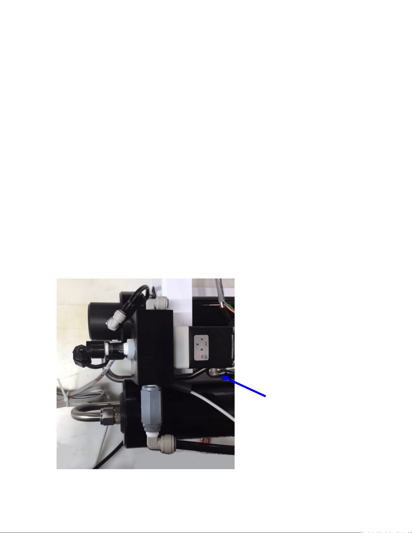
61
In the event of a sensor failure resulng in a shut down due to a false alarm, the failed sensor can
be overridden (page 71 Spectra Connect Sengs). High Pressure, Service Prelter, System Stalled
(airlock), and Salinity Probe Failed can all be overridden and the system will sll run automacally
with all other funcons intact. Be absolutely certain that the alarm is false before overriding the
automac controls.
In the event of complete Connect control failure, the system may be operated manually as
follows:
• Switch on the feed pump by turning the toggle switch to RUN MAN. The automac safety con-
trols are disabled in manual mode. Shut the unit down if the Clark pump does not cycle, if air is
connuously present in the intake line, or if the feed pump is excessively noisy.
• Always discard the product water for the rst few minutes of operaon as the inial product
water may not be potable. Take a water sample by loosening the 1/4-inch product tube ng
at either the feed pump module or the membrane outlet. Check it with a handheld salinity me-
ter or taste it.
• The diversion valve is an electrically operated three-way valve, which is normally energized by
the Connect controls in order to send water to the tank. It will not open automacally in man-
ual mode, and must be opened using the mechanical override buon. The buon is located
on the side closest to the Clark pump cylinder. Push the manual override buon in and rotate
1/4 turn clockwise to open the valve.
Alarm Override and Manual Operation
Diversion valve
manual override
button

62
Bimini 300 Flow Test
The ow test is the most useful diagnosc test for system performance, and should be done before
replacing or cleaning your membrane. Changes in producon or water quality are normally caused
by something other than the membrane, unless the system has been le unused for a long me.
Before the ow test, change all lters and clean the sea strainer. Carefully check for water or air
leaks, as air in the system will cause low producon and errac salinity. Look for air bubbles in the
product ow meter, feed water hoses, and brine overboard hose.
Run the system and watch the feed pressure very closely. If the feed pressure to the Clark Pump is
asymmetrical from one stroke to another, this impedes performance. A dierence of a few PSI is
acceptable, but anything over that is an issue. If the pump is asymmetrical, Clark Pump repairs
should be done before connuing with these tests.
If no asymmetry is noted, connue with this test.
You will need a graduated bucket, either a graduated pitcher or large measuring cup, and a stop-
watch. Log the voltage at the feed pump at the same time. Confirm at least 12.5 Volts at the Termi-
nal Block on 12-Volt DC systems; 25 volts on 24-Volt DC systems.
Take two measurements and compare them with the table on the following page. The first meas-
urement is the product flow alone. The second is the product flow combined with the brine dis-
charge flow to get the total flow or feed flow. You may take these measurements by two methods:
1. Time the product flow into a graduated pitcher, then divert both the product flow and brine dis-
charge together into a bucket, timing them to measure total flow.
OR
2. Divert the product flow into the pitcher while diverting the brine discharge into the bucket. Time
the flow of both at the same time. After calculating the product flow, pour the pitcher of product
into the bucket of brine to measure total flow.
The ratio of product flow to total flow gives us our recovery rate, as a percentage. If the percentage
is below the minimum it indicates an internal leak in the Clark Pump.

63
1. Product Flow: Product flow is expressed in Gallons Per Hour (GPH) or Liters Per Hour (LPH), by
this equation:
3600 ÷ time in seconds x quantity of water in gallons or liters=GPH or LPH
There are 3600 seconds in an hour.
Example: It took 3 minutes and 35 seconds to collect 1 gallon of product water.
3600 ÷ 215 x 1 = 16.74 GPH (3 minutes, 35 seconds is 215 seconds)
Example: It took 2 minutes and 25 seconds to collect 2.5 liters of product water.
3600 ÷ 145 x 2.5 = 62.07 LPH (2 minutes, 25 seconds is 145 seconds)
2. Total Flow or Feed Flow: Feed flow or total flow (brine + product) is expressed in Gallons Per
Minute (GPM) or Liters Per Minute (LPM) , by this equation:
60 ÷ time in seconds x quantity of water in gallons or liters = GPM or LPM
Example: It took 1 minute and thirty-seven seconds to collect 5 gallons of total flow.
60 ÷ 97 x 5 = 3.09 GPM (1 minute, 37 seconds is 97 seconds)
Example: It took 53 seconds to collect 12 liters of total flow.
60 ÷ 53 x 12 = 13.58 LPM
3. Recovery Rate: Product Flow ÷ Total Flow = Recovery Rate %
Example: 6.5 GPH product flow = .063 or 6.3%
1.7 GPM total flow x 60
(you must first multiply total flow by 60 to convert from GPM to GPH)
*pressure relief valve open ½ turn
In order to make good quality product water, you need the proper amount of feed water ow, as
in the table below. Compare the product ow to the total feed ow. Product ow should be 9.0%
of total ow for a Bimini 300. If product percentage is low, you may have an internal leak in the
Clark Pump.
For every
1
/
10
th
of a GPM feed water ow loss, we will lose about
1
/
2
gallon per hour of product
ow and the salinity will go up 100 PPM.
Low feed ow combined with low system pressures is most frequently caused by a worn pump
head.
System
AMPS Feed Pressure Stac * Total Flow/Feed Flow Product Flow
12V
MAX 24V MAX PSI bar PSI GPM LPM
GPM
(min)
LPM
(min)
GPH LPH
GPH
(min)
LPH
(min)
Bimini 300 HI 19.5 21.5 9.75 10.75 80-90
5.6-
6.3
25-30 2.4 9.1 2.3 8.7 12.5 47.3 12 45.4
Bimini 300 LO 14 16 6.75 7.75 65-75
4.5-
5.2
25-30 1.7 6.4 1.6 6.0 9 34.0 8 30.2

64
Poor Product Water Quality
With any product water quality issue, you must ensure accurate calibraon if you are using a
salinity meter. For general quality evaluaon, your taste is always good enough.
Membranes are not an exact science and two idencal systems can have dierent product
quality. World health standards deem water of up to 1000 PPM of total dissolved solids ac-
ceptable for drinking. We consider any thing below 750 PPM acceptable but not ideal, and
anything below 500 PPM excellent. Factors that could aect water quality are addressed be-
low.
LOW SYSTEM FLOW OR PRESSURE will equate to lower product quality (higher PPM). Bi-
mini systems, which have a higher feed to output pressure rao (See nominal pres-
sures under Flow Test, page 45), as well as a higher feed ow/membrane area rao,
will produce water in the 150-300 PPM range.
DAMAGE TO THE MEMBRANE by chlorine contaminaon. Flushing the system with chlo-
rinated water will irreparably damage the membrane. Charcoal lters are used to ab-
sorb any chlorine which might be present in ush water. They must be of proper
specicaon to be suitable. There is no test for chlorine damage except the process
of eliminaon of other causes.
DIRTY OR SCALED membranes. A dirty (foreign material), scaled (mineral deposits), or
contaminated (bacterial growth) membrane can result in poor water quality and ab-
normal operang pressures. If operang pressures are above normal, then cleaning is
indicated. If the system pressures are within operang normal range, cleaning may
have lile result. Avoid cleaning as a diagnosc tool. Low water quality aer storage
with propylene glycol can usually be remedied by extended ushing or an SC-2 clean-
ing.
MECHANICAL LEAKAGE within the membrane pressure vessel. This is an unlikely but pos-
sible cause of poor water quality. A pinched or damaged O-ring within the pressure
vessel, a scratch on the product tube on the membrane, a scratch within one of the
end caps, or a seal fouled by contaminaon could allow sea water into the product
water.
If system total ow (product plus brine) is 2.4 GPM (9 liters) or above, the membrane is
clean, the product ows are consistent with the system ow and the water quality is sll not
acceptable, then replacement of the membrane is indicated.
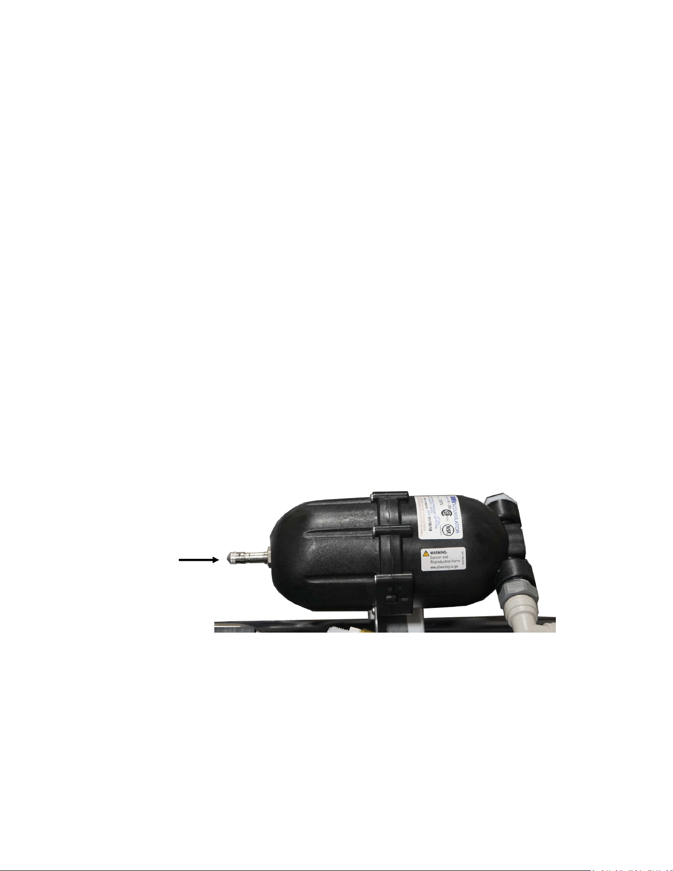
65
Technical Bulletins
The following pages include Spectra’s most commonly-used technical bullens, covering tests,
adjustments, troubleshoong, and common points of confusion. Many more technical bulle-
ns are available on the Spectra website, www.spectrawatermakers.com.
ACCUMULATOR PRESSURE
Your Bimini 300 is supplied with a pressure accumulator tank (PL-ACC-TK) installed in the feed
water line between the feed pump and the Clark Pump.
The purpose of the feed line accumulator is to reduce the spikes in the feed pressure caused
by the cycling of the Clark Pump. If the accumulator is not properly charged it can lead to pres-
sure spikes and system shut down. The accumulator has a Schrader air valve, like a car re,
which allows the internal air bladder of the accumulator to be pre-charged. The accumulator
should be pumped up to about 60 psi (4.1 bar) for best results. Add air using a re pump or air
compressor. You can experiment with the exact pressure that will give the best pulsaon
dampening on your installaon.
Schrader valve
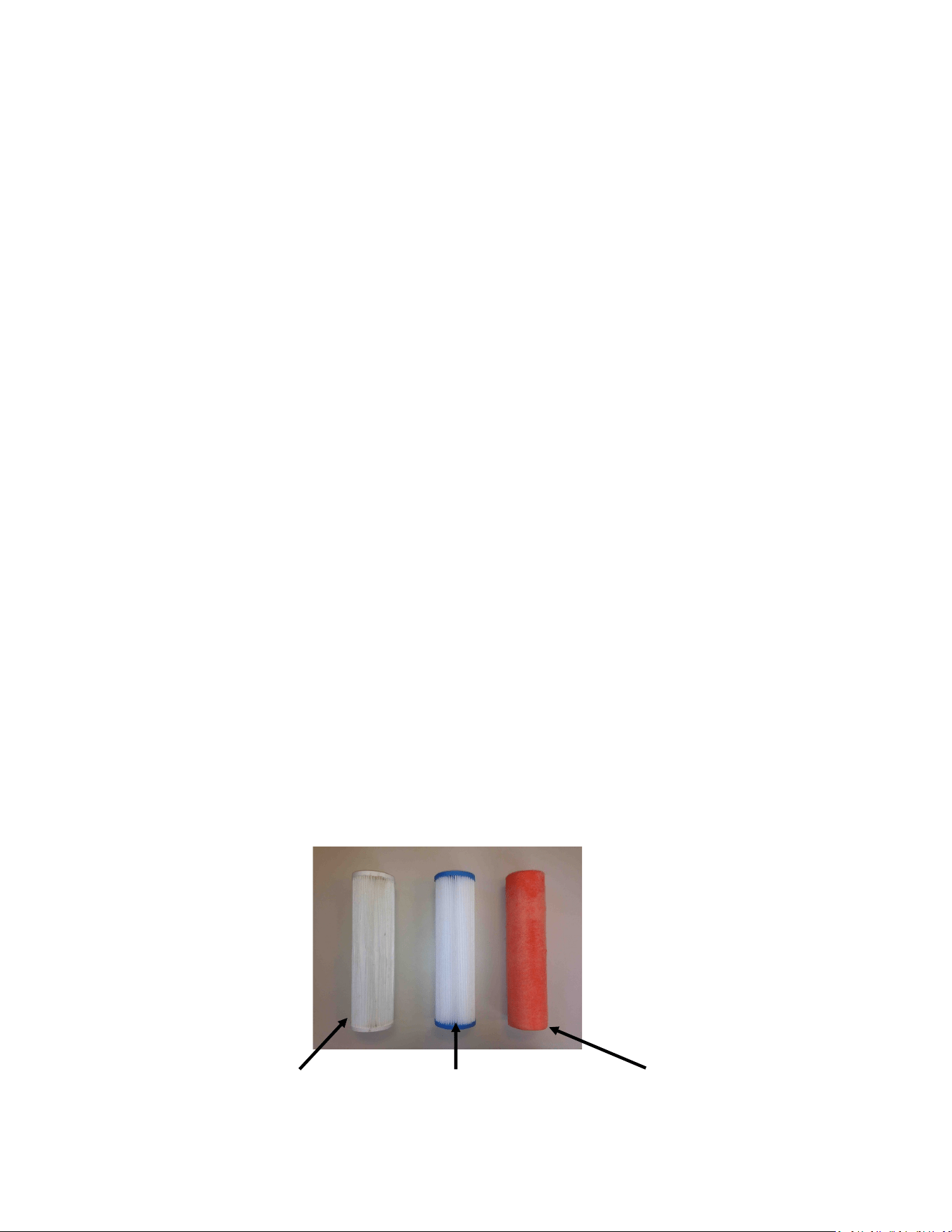
66
Prefilters
During normal operaon, the feed water is ltered in two stages. First it passes through a ne
mesh metal sea strainer, which protects the boost pump from foreign materials and sea crea-
tures. Aer passing through the boost pump, the feed water passes the lter housings con-
taining the 5 micron element, removing very ne parcles that could damage the feed pump
or Clark Pump and shorten membrane life. An addional carbon lter prevents the entrance of
chlorine during fresh water ushing (see next page).
Prelter maintenance schedules will vary widely depending on how and where the system is
used. If large amounts of feed water are run through the system in biologically ferle near-
shore waters the prelter will plug up, water producon and quality will drop, and the system
pressure will change dramacally. In blue water condions the prelter may only need to be
changed every week or two.
When operated for only an hour or two a day in inland or near-shore waters, the trapped
plankton will begin to decay in the lters long before the elements plug up. The decaying
plankton and bacteria will cause a roen egg smell in the product water. This decay will set in
overnight in tropical waters, or aer a week or two in higher latudes. If handled gently and
changed regularly before they get too smelly, lters can be cleaned several mes. (See
Maintenance, page 59.)
Our lter element part numbers are FT-FTC-XX, where the last digits indicate the micron
rang. FT-FTC-5 is for a 5 micron element, FT-FTC-20 is a 20 micron element. The oponal oil/
water separator is FT-FTC-OW.
5 Micron
20 Micron Oponal Oil/Water Separator

67
Charcoal Filters
The charcoal lter element (FT-FTC-CC) removes chlorine from the fresh water ush water
supply, as the RO membrane can only handle small amounts of chlorine without permanent
damage.
The charcoal lter used for the fresh water ush system will not plug up unless you have very
dirty domesc water in your boat’s supply tank.
The charcoal lter we supply removes 99.7% of the chlorine. Beware when buying other char-
coal lters. If they don’t specify the percentage of chlorine removed, don’t use them. Cheap
ones may remove only 60% or 70%. Also, there are aermarket lters which are very close to,
but not exactly the right dimensions, and they will not seal in the housing. If you skimp on the
charcoal lter you risk damaging a $600.00 membrane on the rst ush. The other factor is
the ow rate that the lter can handle. Because the chlorine is adsorbed by the charcoal, it
must remain in contact with the charcoal for a sucient period of me for the all of the chlo-
rine molecules to be captured. The lters we use can handle 1.5 gallons (6 liters) per minute
ow, and are good for 3000 gallons (12,000 liters) at 1.5 GPM, or six months, whichever
comes rst. Regardless of the amount of water treated, the charcoal loses its eecveness
aer six months.
Charcoal lter, Spectra part number FT-FTC-CC

68

69
Spectra Connect Programming &
Controls

70
Spectra Connect Settings
Your new Spectra Connect is designed to make your watermaker easier than ever to operate,
maintain and enjoy. This secon will guide you through some of the more advanced sengs
opons available.
Always use cauon when changing any factory default sengs, as serious damage can
occur.
The Spectra Connect automacally monitors the operaon of the system to ensure a long and
trouble-free service life. If an operang parameter changes, the Connect can switch operang
modes, shut itself down, or automacally store itself in order to protect your watermaker.
It includes advanced calibraon sequences to make proper setup and maintenance of your
watermaker easier than ever.
The onboard me clock feature allows for temporary power interrupons without detrimental
eects on the system. In some cases your watermaker will connue to funcon in its last
known operang state.
The Spectra Connect has built in data logging, allowing for easy access to historical operang
data—which can indicate a wearing component or spares to be carried along before a failure
occurs.
Built in warnings for preventave maintenance automacally alert a user of pending
maintenance items, helping to keep your watermaker’s up-me to 100%! Advance warnings
are pre-programmed for Prelter Life, Clark Pump rebuilds, feed pump heads, membranes, Z-
Ion reactor rod life, and carbon lter life. These warnings are reseable, allowing you to
perform the maintenance before a catastrophic failure, then reset the interval—so you’re
always on top of the maintenance cycle!
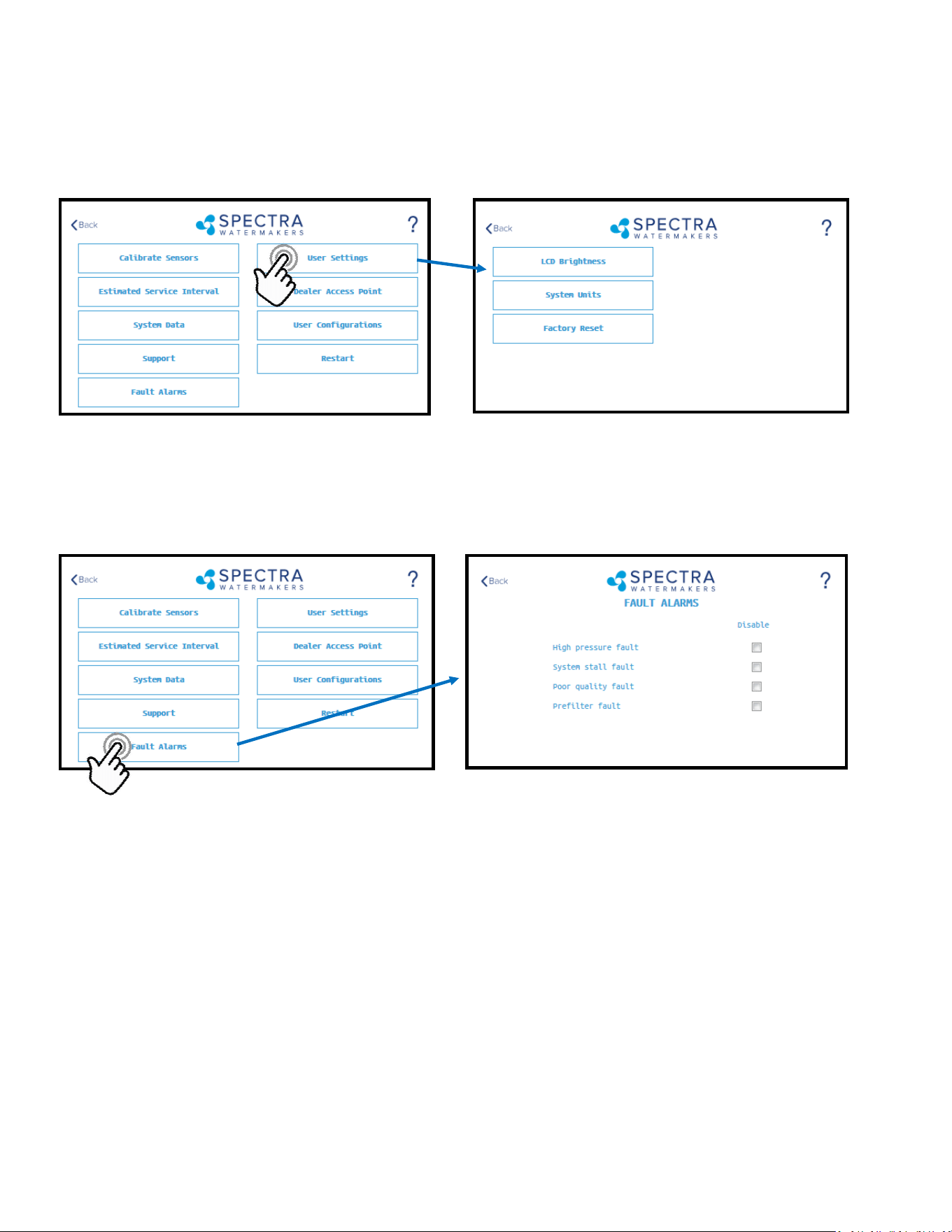
71
LCD Brightness: Set brightness of the hardwired display(s) from 10—100%
System Units: Change from US Standard units to Metric
Factory Reset: Resets any changed parameters a user has made back to the factory defaults for that congura-
on.
CAUTION! Never disable a Fault Alarm without being certain that the issue is with a bad sensor. Dis-
abling a fault and running the system can cause serious damage or injury.
High Pressure Fault: Disables the ‘High Pressure’ shutdown fault in the event of a feed pressure sensor failure.
System Stall Fault: Disables the ‘System Stalled’ shutdown fault in the event of a failed rotoow sensor. System
stalled alarms occur when the control board does not sense any product water being produced, and shuts down
to protect the pump from running dry.
Poor Quality Fault: Disables the ‘High Salinity’ shut down fault in the event that the salinity probe has failed or
cannot be calibrated within range. NOTE: The diversion valve will always be acve when this fault is disabled.
ALWAYS VERIFY PRODUCT QUALITY BEFORE DRINKING. Serious health risks may occur.
Prelter Fault: Disables the ‘Service Prelter’ shut down fault in the event that the boost pressure sensor has
failed or cannot be calibrate within range. CAUTION: Permanent damage to the feed pump can occur if this
fault is disabled, use cauon when operang this system with this fault disabled.
User Settings
Spectra Connect Settings - Cont.
Fault Alarms
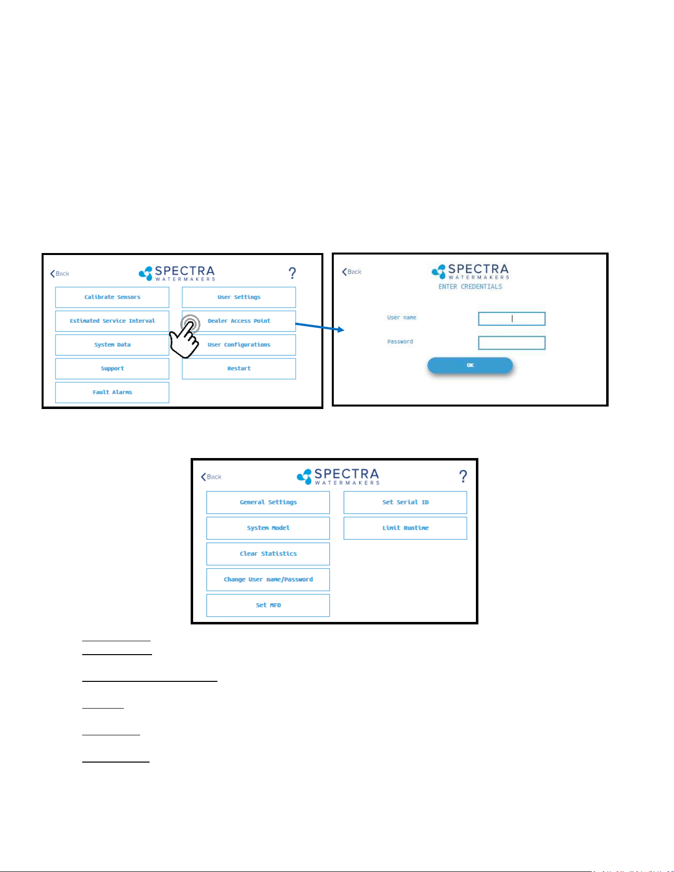
72
Settings
Dealer Access Sengs
It is highly recommended that users consult with a factory trained technician before altering any sengs behind
the ‘Dealer Access Point’. Changing this sengs without understanding the full eect of each change can void
the warranty of your system, and cause irreparable damage.
If any sengs are inadvertently changed, they can be reverted back to the defaults by using the ‘Factory Reset’
feature.
Default Login: admin
Default Password: admin
System Model: Congures the Spectra Connect for a dierent system model from a preset list of opons.
Clear Stascs: Resets all of the Esmated Maintenance Intervals back to 100%. This feature should only be
used on a brand new system.
Change Username/password: Changes the default username and password. If you forget your changed
username and password, a Factory Reset will revert back to the default username and password.
Set MFD: Changes the Manufactured Date on the system. This should only be adjusted if a control board is being
replaced on an older system.
Set Serial ID: Changes the Serial Number recorded in the Spectra Connect. This should only be adjusted if a con-
trol board is being replaced on an older system.
Limit Runme: Limits the maximum run me for the system before shung down and fresh water ushing. Dis-
abling this seng allows the watermaker to be operated 24/7.
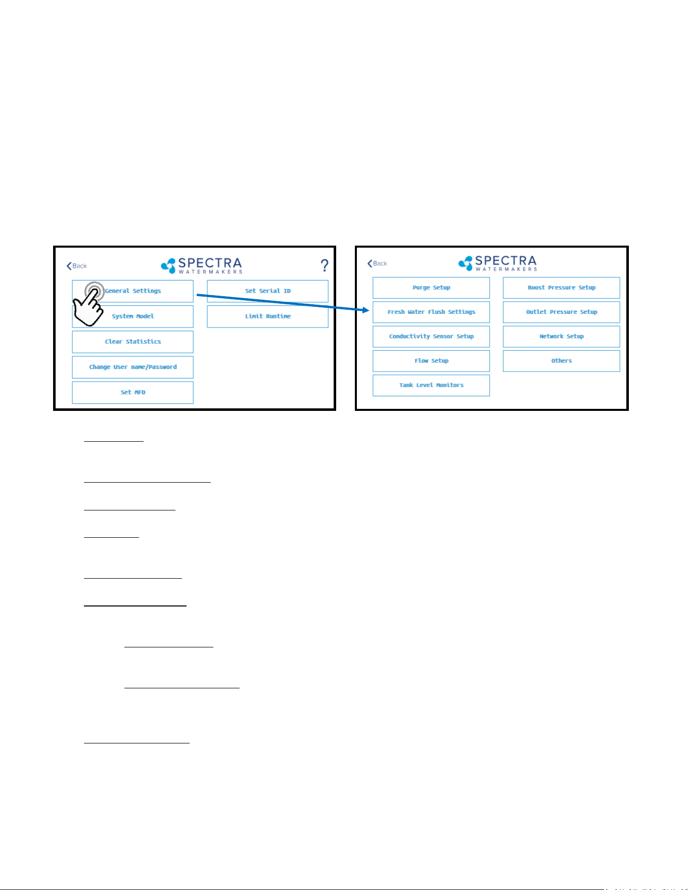
73
Settings
Dealer Access Sengs
It is highly recommended that users consult with a factory trained technician before altering any sengs behind
the ‘Dealer Access Point’. Changing this sengs without understanding the full eect of each change can void
the warranty of your system, and cause irreparable damage.
If any sengs are inadvertently changed, they can be reverted back to the defaults by using the ‘Factory Reset’
feature.
Purge Setup: Adjusts the me and maximum feed pressure allowed for the Purge Mode. CAUTION: Permanent
damage to the membrane can occur if this seng is adjusted. Consult the factory before making any adjust-
ments.
Fresh Water Flush Sengs: Allows adjustment of the fresh water ush duraon and the interval between ush-
es. If the Z-Ion is installed, the Flush Interval should be changed to 30 days.
Conducvity Setup: Allows for enabling or disabling conducvity sensors on the feed water and product water.
Set the threshold for the diversion valve to divert water to the tanks.
Flow Setup: Allows the user to adjust the ow sensor sengs, or disable a ow sensor circuit altogether. DO
NOT USE THIS SETTING TO CALIBRATE THE PRODUCT FLOW. Follow instrucons on calibrang the ow sensor in
this manual.
Tank Level Monitors: Enable and disable the Tank Level Sensors, which read the % remaining in the tank, and
the tank switches, which allow the system to turn on/o automacally.
Boost Pressure Setup: Enable alternate Boost Pressure sensors, change the Low Vacuum Limit, or Boost Pressure
Setpoint. CAUTION: Permanent damage to the pump can occur if this seng is adjusted. Consult the factory
before making any adjustments.
Low Vacuum Limit: The minimum boost pressure required at the inlet to the pump. This seng pre
vents the pump from geng damaged by running under high vacuum. Adjusng it to a lower number in
creases the risk that the pump will suer damage during normal operaon.
Boost Pressure Setpoint: During startup the controller turns on the boost pump and waits for the Boost
Pressure to reach the Boost Pressure Setpoint. If the boost pressure fails to reach this setpoint, then the
main pump won’t turn on. Reducing the Boost Pressure Setpoint may cause the system to start, then
immediately shut down due to low boost pressure.
Outlet Pressure Setup: Set High Pressure Limit, enable alternate high pressure sensors, select pressure sensor
scaling. CAUTION: Permanent damage to the pump can occur if this seng is adjusted. Consult the factory
before making any adjustments.
Network Setup: Enabling the Spectra Connect Wireless access turns on a Power Over Ethernet feature on the
wired connecon. ENABLING THIS FEATURE CAN CAUSE SERIOUS DAMAGE TO YOUR SHIP’S NETWORK. DO
NOT ENABLE THIS FEATURE WITHOUT CONSULTING A QUALIFIED TECHNICIAN OR THE FACTORY.
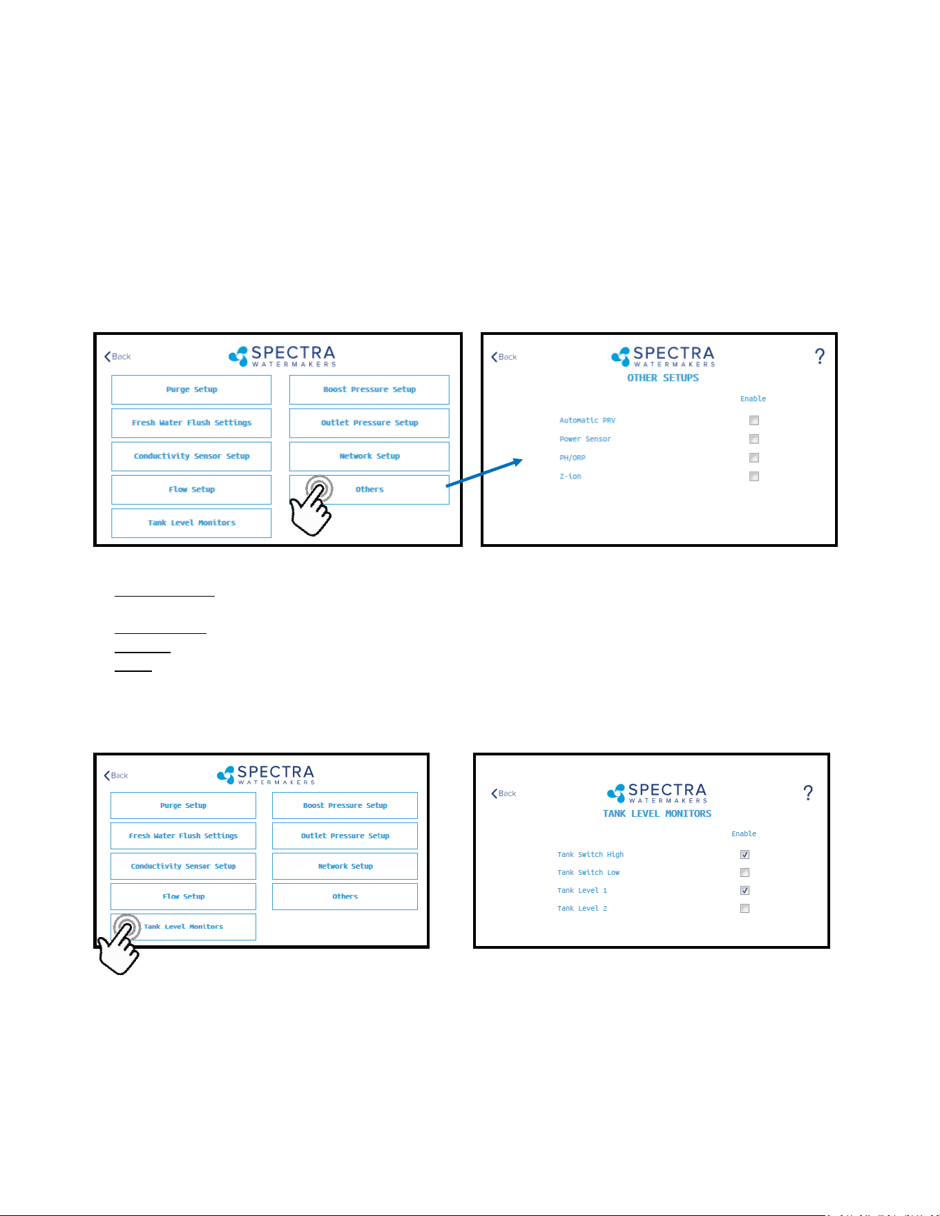
74
Settings
Dealer Access Sengs
It is highly recommended that users consult with a factory trained technician before altering any sengs behind
the ‘Dealer Access Point’. Changing this sengs without understanding the full eect of each change can void
the warranty of your system, and cause irreparable damage.
If any sengs are inadvertently changed, they can be reverted back to the defaults by using the ‘Factory Reset’
feature.
Automac PRV: Enables an oponal Automac Pressure Relief Valve, aer it is installed. This seng should re-
main o unless you are certain that you have this feature installed on your system.
Power Sensor: Enables or disables an oponal power sensor, aer it is installed.
PH/ORP: Enables an oponal pH or ORP meter, aer it is installed.
Z-Ion: Enables or Disables the oponal Z-Ion system, aer it is installed. If the Z-Ion is enabled, you should also
adjust the Flush Interval to 30 days.
Tank Level Monitors
Tank Setup - Enable/disable tank sensors.
Enable Tank Switch High - Enable/disable tank switch high. If this is disabled Auto Fill and Fill Tank
run modes will not be available.
Enable Tank Switch Low - Enable/disable tank switch low. If this is disabled Auto Fill mode will not
be available. Both High and Low tank switches must be enabled for Auto Fill mode.
Enable Tank Level 1 - Enable/disable tank level sensor 1. If this is disabled there will be no tank level
reading and tank level gauge will read “!”.
Enable Tank Level 2 - Enable/disable tank level sensor 2..

75
Fault Handling
Faults are hazardous condions that might occur during running of your watermaker. The control board has the
ability to monitor these faults in real me and take necessary acons to prevent damaging your equipment.
HIGH PRESSURE FAULT
High pressure fault is triggered if
Outlet pressure (Feed/Membrane pressure) > Pressure Limit
If a high pressure fault is triggered, the system goes to low producon mode if it is running in high producon
mode, or stops the operaon if it is already running in low producon mode. Then the system will begin
the Auto Store mode.
Resoluons
Check for kinked or blocked hoses.
Conrm “#3 Sensor PSI High limit” and “#3 Sensor PSI Oset” opons on Outlet Sengs.
Clean membrane.
SYSTEM STALL FAULT
System stall fault is triggered if
There is no product ow for 1 minute connuously.
If system stall fault is triggered, machine will stop the current run cycle and will prompt to restart. If restarted
it will retry the previous running mode. If the stall condion persists even aer restart, the system will
begin the Auto Store mode.
Resoluons
Conrm product water at membrane endcap.
Check intake line for restricons, blockages or air leaks.
Close Pressure Relief Valve on Pump.
Conrm controller sengs correct.
SERVICE PREFILTER FAULT
The Service Prelter fault is triggered if
Inlet Pressure (boost pressure) < Low Vacuum Limit
If the Service Prelter fault triggers, the system goes to low producon mode if it is running in high produc-
on mode or stops the operaon if it is already running in low producon mode. Then the system will
begin the Auto Store mode.
Resoluons
Change prelters and the sea strainer screen.
Conrm adequate boost pressure in inlet pressure sengs.
Check for obstrucons in intake line.
Check sensor for proper operaon
POOR QUALITY FAULT
The High Salinity fault triggers if
The Salinity of the product water is above the threshold (measured salinity > Salinity 1 threshold) for
more than 8 minutes.
If the High Salinity fault is triggered, the machine will stop the current run cycle and will prompt to restart. If
restarted it will retry the previous running mode. If the High Salinity fault condion persists even aer
restart, the system will begin the Auto Store mode.
Resoluons
Check pump operaon - Clark Pump (pressure relief valve closed), Feed Pump (moving water).
Conrm product water quality.
Membrane damage - clean or replace.
Salinity probe out of calibraon.
Clean or replace salinity probe.
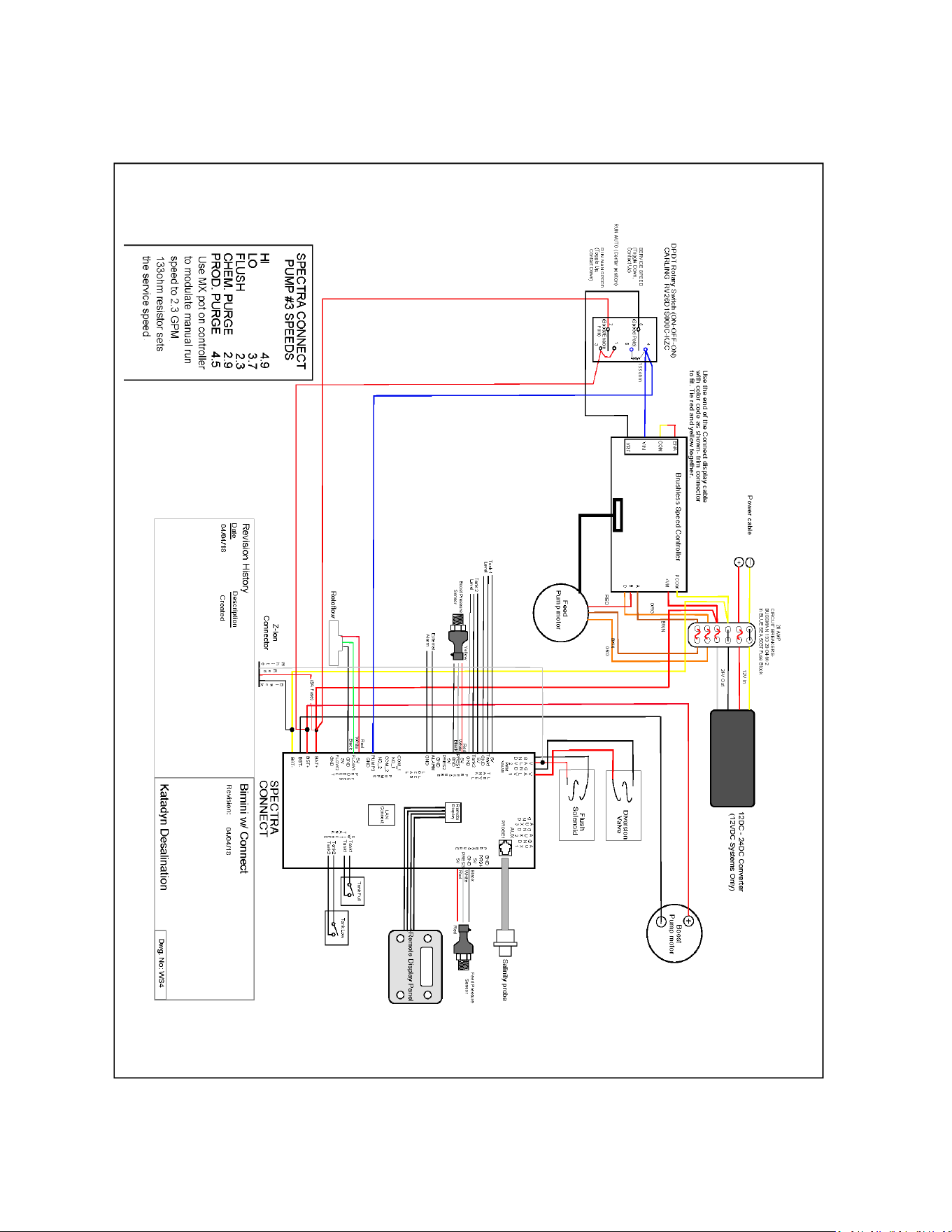
76
Wiring Schematic

77
Electrical Specifications
Operang voltage limits: 10—32vdc
Outputs: 5VDC:– 2000mA Total for all outputs.
VLV 1&2: 1 Amp DC priming valve solenoid.
AUX 1-3: 1 Amp DC auxiliary output.
Never connected anything to the Spectra Connect without factory approval. Serious damage
can occur!

78

79
Exploded Views & Part Numbers

80
KIT-PV-25EP1
Pressure Vessel
End Cap Kit
FT-PV-ER
Pressure Vessel
End Ring
PL-SWF-1/8X1/4J
1/8” NPT to 1/4”
Tube Parker Elbow
Exploded Views and Part Numbers
FT-PV-40
40” High Pressure Vessel
PL-MTS-3/8X1/2B
3/8"NPTX1/2"Tube Fitt. St.
SO-HPP-CT
Connector O-ring
PL-HP-1/8
1/8NPT Nylon Hex Plug
PL-TB-HPTPVUL
Pump to Pressure Vessel
Upper SS Tube Long
PL-MTS-3/8x3/8J
3/8NPT x 3/8” Tube John Guest Straight
Fitting
SUB-CT-Z-HPILHA
CT 300 Quick Disconnect
PL-TEE-1/2TJG
John Guest 1/2-inch swivel tee
PL-STA-12Tx38NJ
1/2”Tube Stem x 3/8” NPT
adapter John Guest
Accumulator Hose:
20 inches 1/2-inch vinyl hose PL-HS-1/2VN
(2) brass ferrules PL-HF-.75lDX1BR)
(2) 1/2-inch hose barb tube adapters PL-HBA-1/2Tx1/2
5 inches of 3/4-inch spiral wrap EL-LT-3/4SW
Hose clamps may be substituted for the brass ferrules,
which are crimped on.
PL-ACC-TK
Accumulator Tank
PL-HP-1/2N
1/2” PLUG NYLON
PL-SWF-1/2x1/2
1/2”NPT x 1/2” Tube
John Guest swivel elbow
Accumulator
High Pressure Module
PL-TB-HPTPVLL
Pump to Pressure Vessel
Lower SS Tube Long
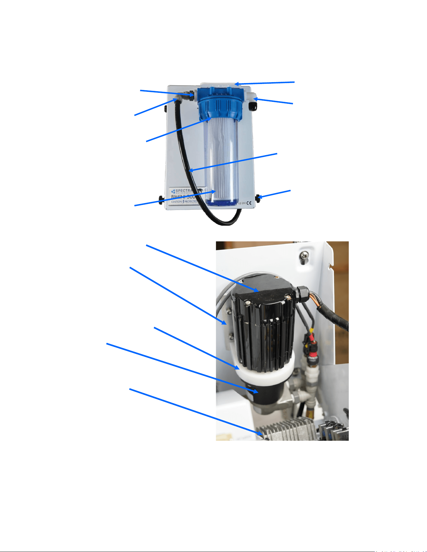
81
Part Numbers
PL-PMP-140MAG
MAG DRIVE PUMP
FT-FTC-5
5 MICRON FILTER ELEMENT
FT-FTH-10L3PCS
3 PIECE 10” FILTER HOUSING
PL-HBE-3/4X3/4
3/4” NPT X 3/4” HOSE
BARB ELL NYLON
PL-NP-1/2X3/8N
1/2"NPT X 3/8"NPT
CLOSE NIPPLE NYL
FT-FHB-3PCSHSS
MOLDED FILTER
BRACKET
PL-SWF-1/2X1/2
1/2"NPT X 1/2” TUBE
SWIVEL ELBOW
PL-NLT-1/2LP
1/2" LOW PRESSURE
TUBE
HD-OTH-1/4TS1D
1/4"-20 x 9/16” NYLON
THUMB SCREW 1D
EL-MTR-1/5BLM24
1/5HP BRUSHLESS MO-
TOR 24V
FM-CT-BDCMTBP
CATALINA BDC MOTOR ADAPTOR
FM-CT-BDCMAD
CATALINA BDC MOTOR BASE
PLATE
EL-PS-24V480WDC
DC-DC STEP UP 12V/24V
480W WEATHER GUARD
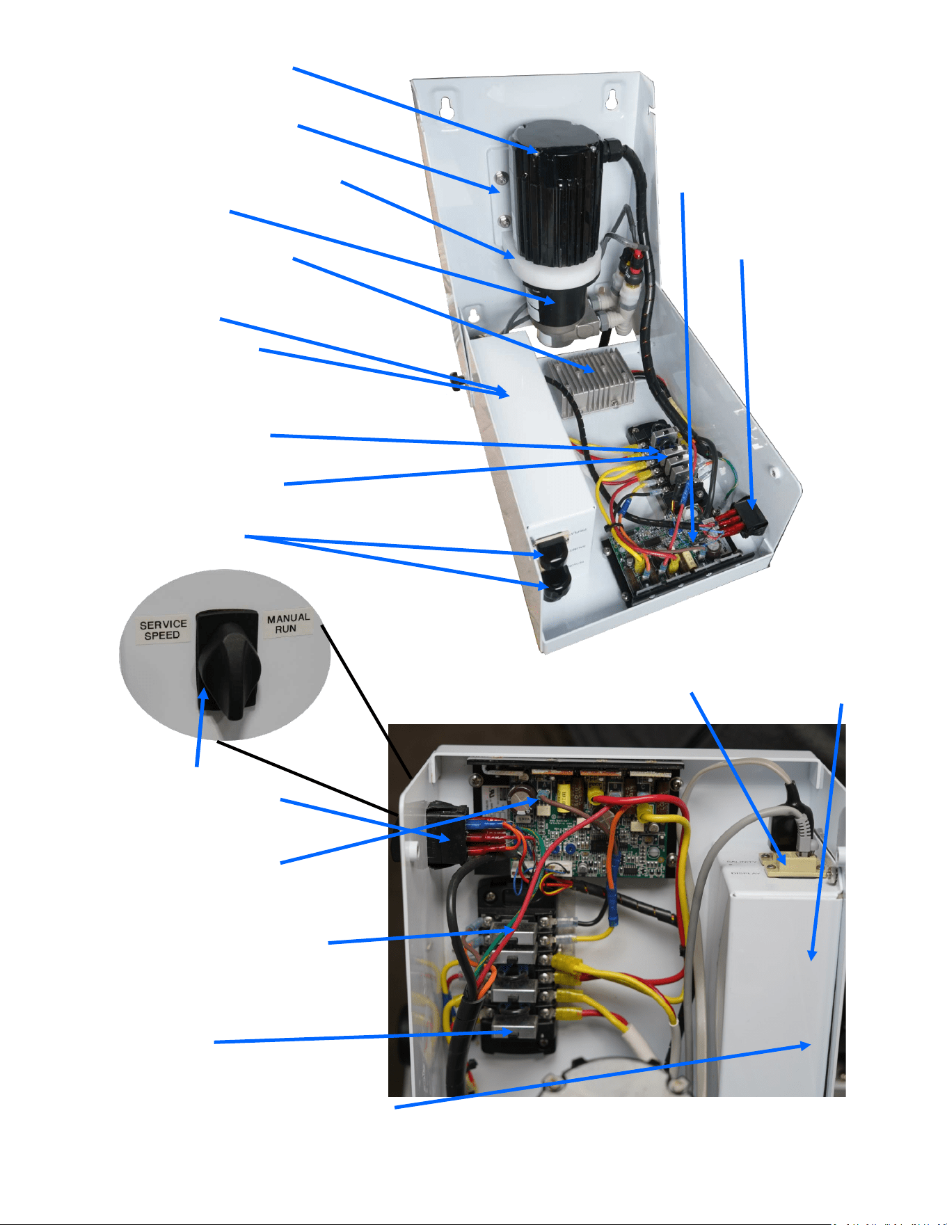
82
FM-MPC-MPCB
MPC BOX
EL-TM-RJ12COUP
RJ-12 Modular
Coupler Panel
EL-TM-30A6CBFB
30A 6-CIRCUIT BLADE FUSE
BOX
EL-RL-3.5A24VIP (inside)
3.5A 24V RELAY IGNITION
PROOF RELAY,
PL-PMP-140MAG
MAG DRIVE PUMP
FM-MPC-MPCB
MPC BOX
EL-TM-RJ12COUP
RJ-12 Modular
Coupler Panel
EL-MTR-1/5BLM24
1/5HP BRUSHLESS MO-
TOR 24V
EL-MTR-1/5BLC24
1/5HP BRUSHLESS MO-
TOR CONTROLLER 24V
FM-CT-BDCMTBP
CATALINA BDC MOTOR ADAPTER
FM-CT-BDCMAD
CATALINA BDC MOTOR BASE
PLATE
EL-PS-24V480WDC
DC-DC STEP UP 12V/24V
480W WEATHER GUARD
EL-TM-30A6CBFB
30A 6-CIRCUIT BLADE FUSE
EL-SWT-DPDT20IP
20A ROTARY SWITCH
DP/DT IG PROTECTION
EL-RL-3.5A24VIP (inside)
3.5A 24V RELAY IGNITION
PROOF
EL-SWT-DPDT20IP
20A ROTARY SWITCH
DP/DT IG PROTECTION
EL-MTR-1/5BLC24
1/5HP BRUSHLESS MO-
TOR CONTROLLER 24V
EL-BRK-20ARSA
20A CIRCUIT BREAKER RESETA-
BLE ATC, 4 per block
EL-BRK-20ARSA
20A CIRCUIT BREAKER RESETA-
BLE ATC, 4 per block
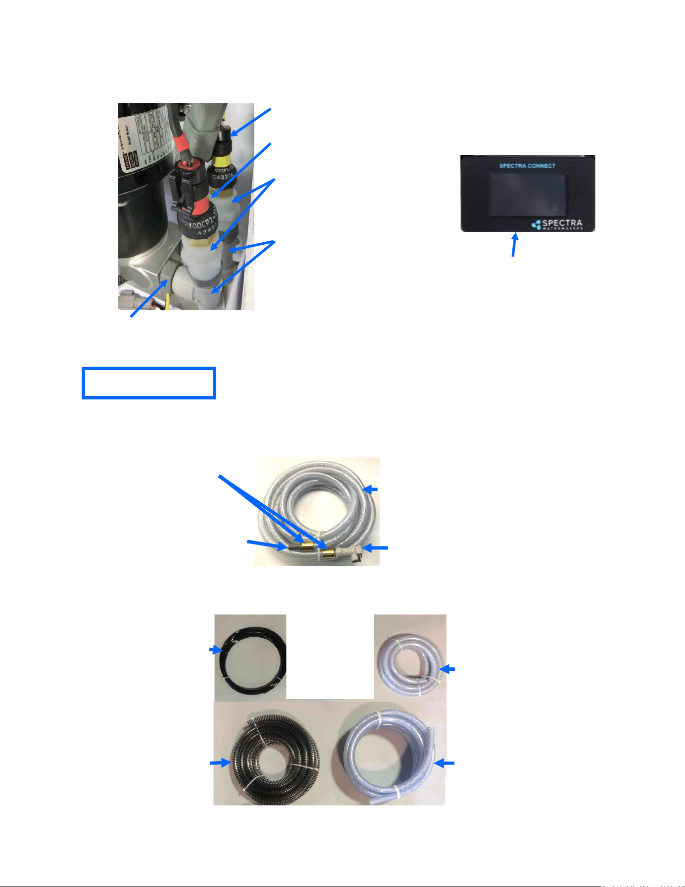
83
EL-SSR-ABS
ABSOLUTE
PRESSUR SENSOR
EL-SSR-150
150 PSI PRESSURE SENSOR
PL-UNN-3/8x1/4N
3/8”FPT x 1/4” FPT
COUPLING NYLON
PL-TEE-1/2TJG
1/2” TUBE TEE JG
PL-STA-12TX38NJ
1/2” TUBE STEM x 3/8” NPT
ADAPTER
PL-HS-3/4SH
3/4" REINFORCED
SUCTION HOSE
PL-HS-3/4VN
3/4" VINYL HOSE
PL-HS-5/8VN
5/8" VINYL HOSE
PL-NLT-1/4LP
1/4” Low Pressure Tube
(Product)
Hoses and Tubes
Note: Hose clamps may be substituted for brass ferrules, which require a special crimper.
Inlet/Flush Hose Assembly (SUB-CT-Z-HPIBHA):
PL-HS-1/2VN
1/2" VINYL HOSE
PL-QDC-1/2HBDWV
1/2” HB QUICK DISCT. BODY
WITH VALVE
PL-HBA-1/2TX1/2
1/2” TUBE x 1/2” HB ADAPTER
Brass ferrules for 1/2-inch hose
(PL-HF-.75lDX1BR)
Part Numbers
KIT-SC-RMPNLD Display
Only
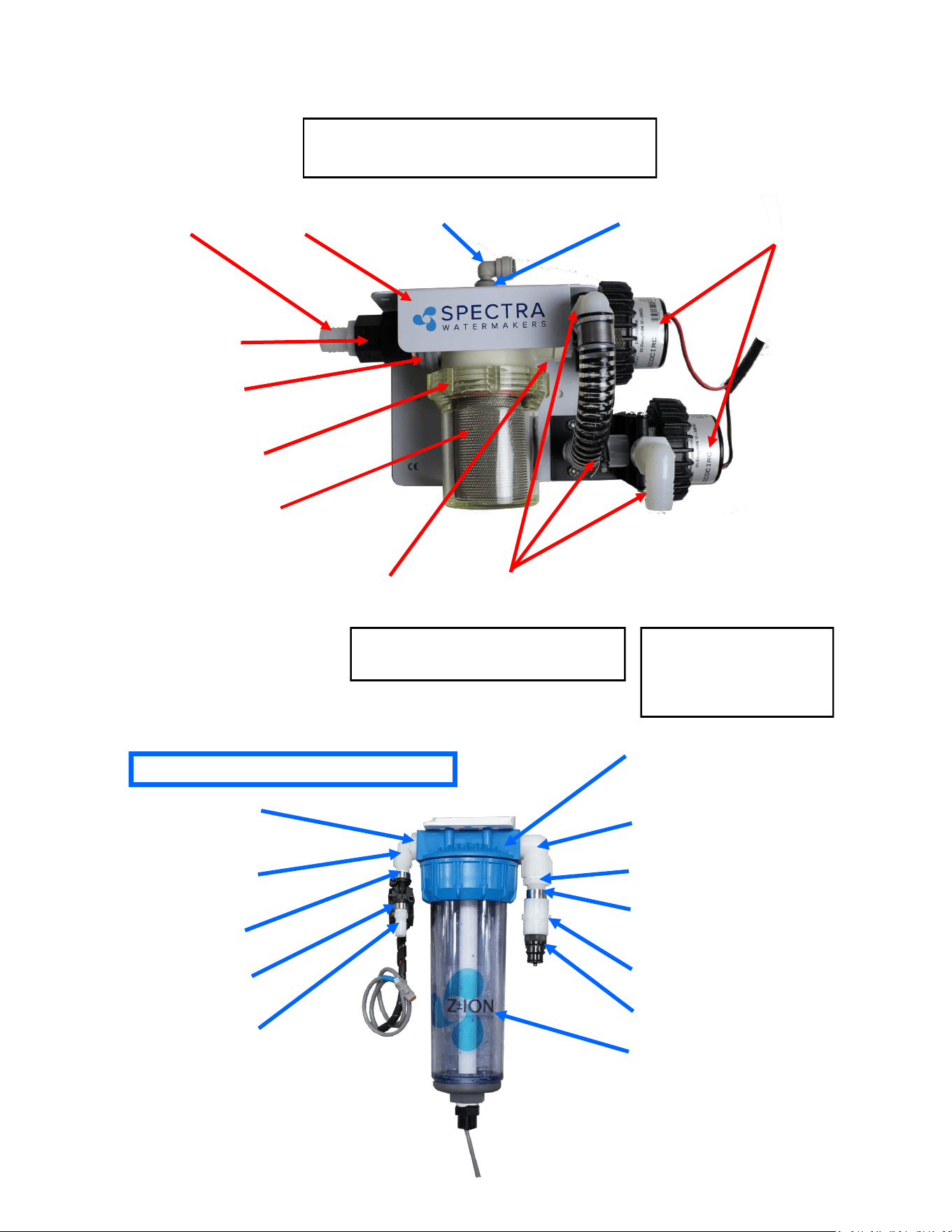
84
Part Numbers
PL-NP-3/4X1/2N
3/4"NPT X 1/2"NPT CLOSE
NIPPLE NYL
PL-MFF-3/4X3/4
3/4” NPT X 3/4"FPT ELBOW
FITTING NYLON
PL-FRG-1/2MF1.5
1/2" NPT –FPT FLOW REGULATOR
1.5 GPM 20-80 psi
FT-FTC-CC
CHARCOAL FILTER
(filter catridge not shown)
PL-HBS-1/4X1/2
1/4" NPT X 1/2" HOSE
BARB ST. NYLON
PL-MFF-1/4X1/4
1/4"NPT X 1/4"FPT
ELBOW FITTING NYL
PL-BSH-3/4X1/4N
3/4" X 1/4" HEX
BUSHING REDUCER NYLON
PL-NP-1/4N
1/4" NPT CLOSE
NIPPLE NYLON
Fresh Water Flush Module or Z-Ion
Fresh water flush module
without Z-Ion will have the
same parts, minus modified
filter bowl and electronic box
on top.
PL-SLN-1/4O12SV
12V FRESH WATER
FLUSH SOLENOID
PL-UNN-1/2N
1/2" FPT COUPLER NYLON
PL-QDC-1/2CP
1/2" NPT COLDER COUPLER
FT-FTH-10L3PCS
10" LOW PRESS. FILTER HOUSING
3 PCS (without Z-ION)
PL-HBS-3/4X3/4
3/4" NPT X 3/4" HOSE
BARB ST. NYLON
PL-CKV-1M3/4FWS
1"MPT X 3/4" FPT
CHECK VALVE W/S
EL-FP-BPLDC824
300-1K BOOST PUMP
8-24VDC 1/2"NPT
PL-FHB– 1/2x3/4E
1/2"FPT x 3/4” HOSE BARB NYLON
FM-ZION-SBPBRK
Z-ION STRAINER BOOST
PUMP BRACKET
PL-BHF-3/8TSTJG
3/8T BULKHEAD FITTINGNST. JG
PL-BHF-3/8TPIEJG
3/8” TUBE PLUG-IN ELBOW
PL-CLP-114CAR
1-1/4” CARLON CLAMP
SUB-STN-6WBH3/8
6" STRAINER WITH BULK
HEAD FITTING 3/8" TUBE
PL-BSH-1x1/2N
1” NPT x 1/2” FPT HEX REWDUCER NYLON
Sea Strainer & Boost Pump Module
KIT-NP-M2Z-SBPH
Not pictured here:
EL-FUS-15AMICHD 15A MICRO FUSE HOLDER
EL-FUS-5AMIC2 5A MICRO2 FUSE
FT-STN-6S
6” Strainer Screen (Inside)
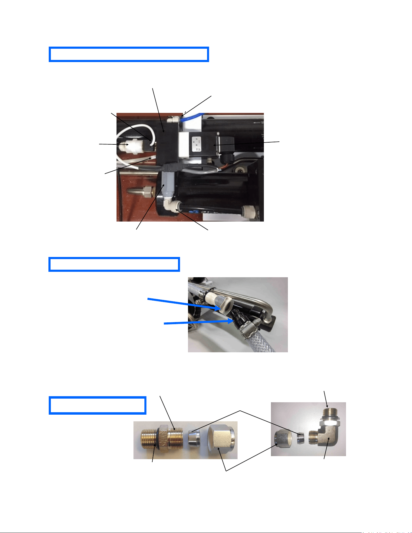
85
Diversion Valve Manifold Assembly
PL-HWR-1/2HN
Stainless Fitting Hex Nut
PL-HWR-1/2FR
1/2” Stainless Ferrule
SO-HPP-CT
Connector O-RING
SO-FT-STF
3/4”-16 Straight Thread O-RING
SUB-MTS-3/8X1/2
Nickel-Bronze High Pressure Straight Fitting
PL-QDC-BD3/8
3/8”NPT Quick Disc. Coupling Body
PL-QDC-HB5/8
5/8” Quick Disc. Fitting Hose Barb
Brine Discharge Quick Connect
High Pressure Fittings
PL-MTE-3/4S1/2B
3/4"-16 ST X 1/2"Tube Fitting
Elbow Bronze
EL-MPC-SP4
SALINITY PROBE
EL-SSR-IFM
INLINE FLOW METER
(0.5-5 L/M)
PL-MTE-1/4x3/8J
1/4”x3/8” TUBE FITT. ELBOW
PL-UNN-3/81/4N
REDUCING COUPING
PL-SLN-1/4D12M
DIVERSION VALVE SOLENOID
PL-MNF-DVMBK1P
DIVERSION VALVE MANIFOLD
PL-MTE-1/4x1/4J
1/4”x1/4” TUBE FITT. ELBOW
PL-CKV-1/4M-F
1/4" PLASTIC CK VALVE (M-F)
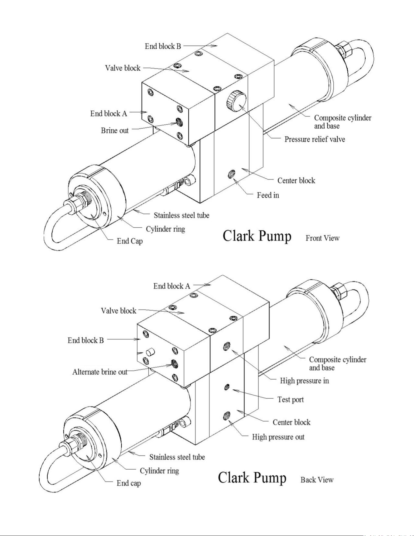
86
HP-TB-VEB-B
HP-TB-VB
HP-TB-VEB-A
HP-TB-BV
HP-CB-CB10
HP-CYL-SST
HP-CYL-R
HP-CYL-EC
HP-CYL-CCA
Not used
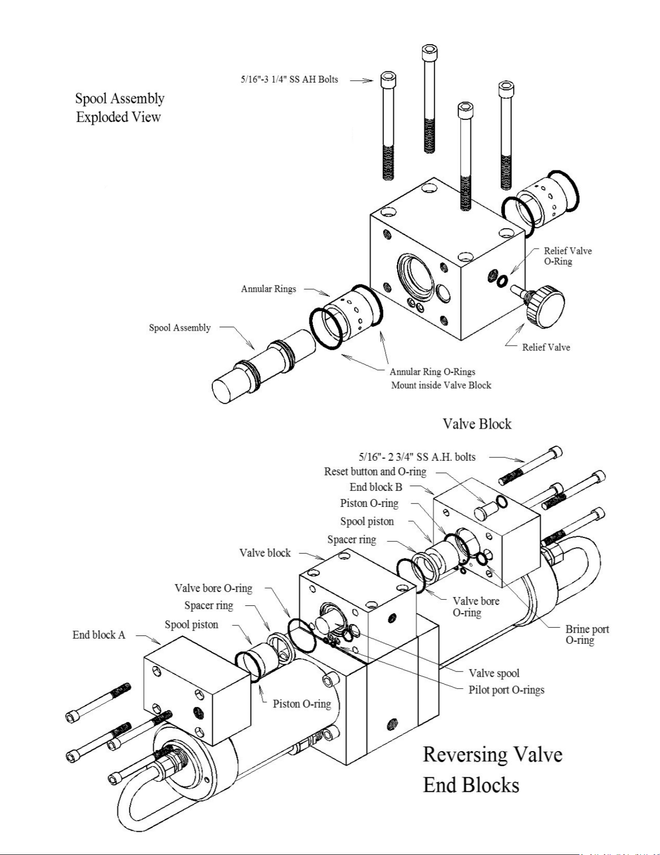
87
HD-CPS-5/162.75
SO-HPP-SP
HP-TB-VSP
HP-TB-SR
SO-HPP-VB
SO-HPP-PLP
SO-HPP-VP
HD-CPS-5/16X3
KIT-HP-10VSA
HP-TB-ARP
SO-HPP-AR1
SO-HPP-RV
HP-TB-BV
89
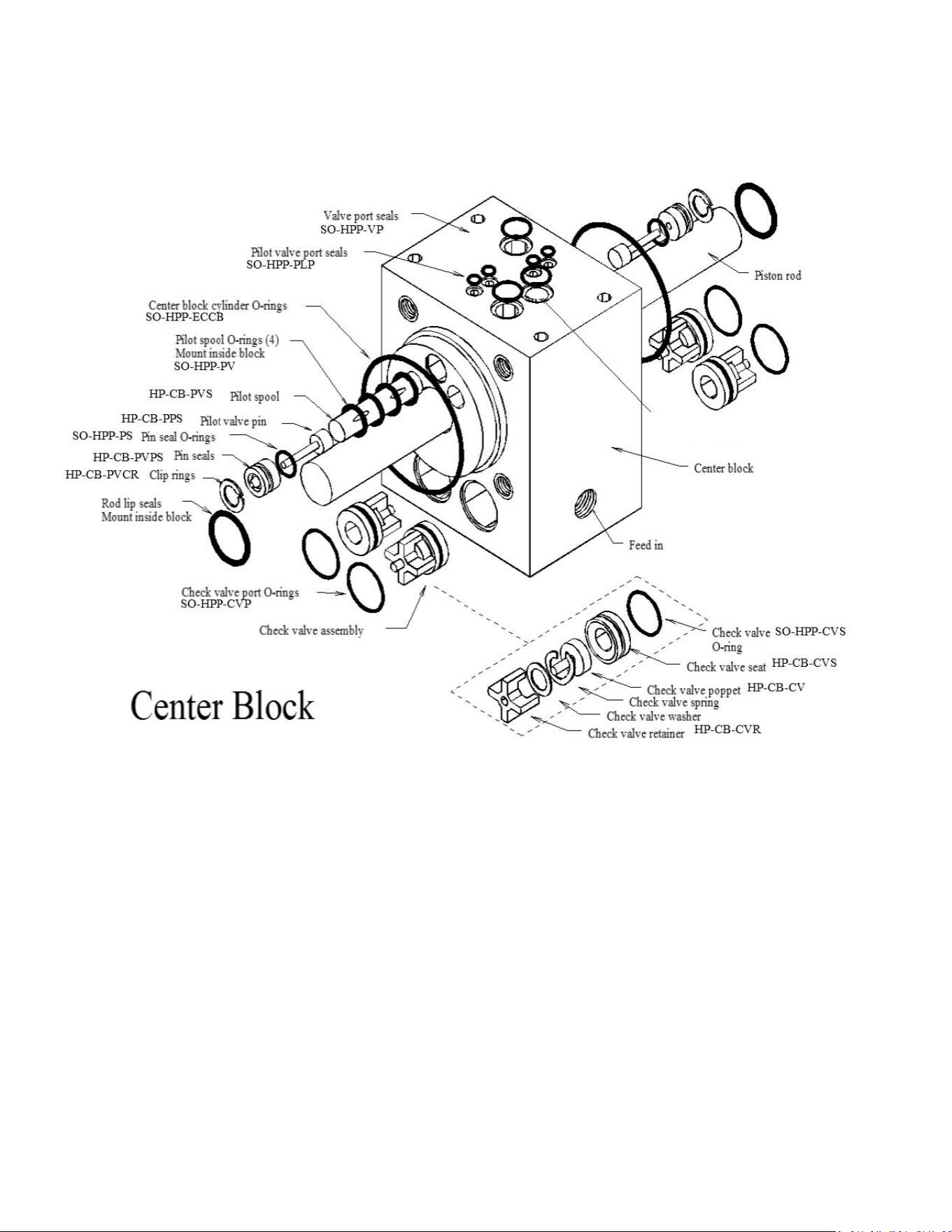
88
Parts
1
SO-HPP-PR10
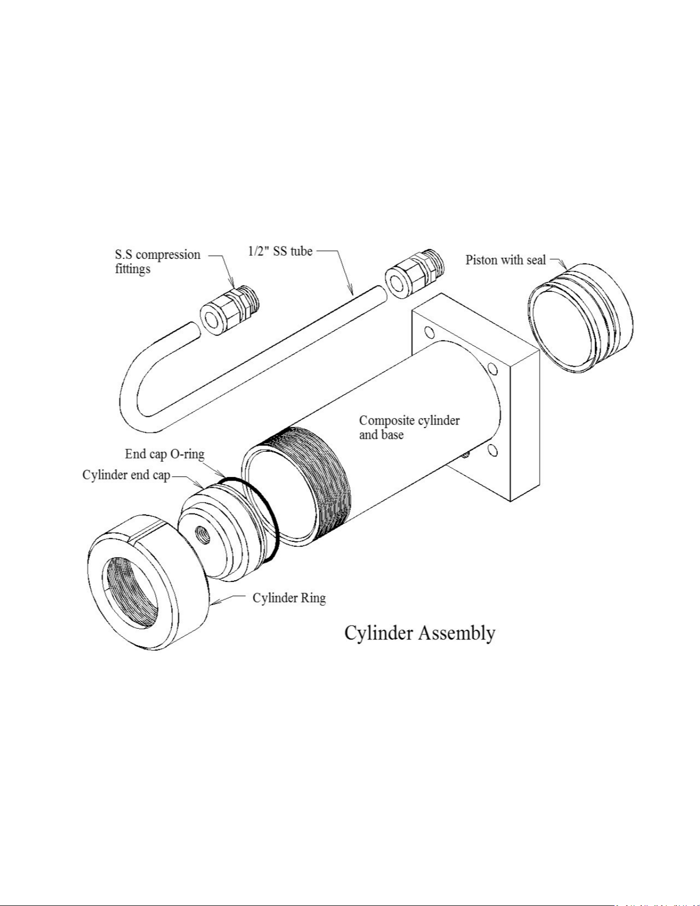
89
PL-MTS-3/8X1/2B
HP-CYL-SST
HP-CYL-CCA
SO-HPP-ECCB
HP-CYL-EC
HP-CYL-R
HP-CYL-PT
Parts

90

91
Owner Resources

92
SPECTRA WATERMAKERS LIMITED LIFETIME WARRANTY
THIS LIMITED WARRANTY APPLIES TO THE ORIGINAL OWNER OF THE WATERMAKER AND IS NOT TRANSFERRABLE
For warranty information regarding products sold within the European Union please contact eu-
rope@spectrawatermakers.com.
This limited product warranty is provided by Katadyn Desalination LLC, a Business Unit of the Katadyn
Group. (“Manufacturer” of “We” or “Our”) to the original, consumer owner of the product (“You” or
“Your”) with which this limited product warranty is provided (the “Product.”)
The Manufacturer warrants to You that the product will be free from defects in material and workmanship
under normal use and regular service and maintenance, subject to the exclusions described below, for a period
of
year (the “Warranty Period”) after date of installation, or 15 months after the shipment date, whichever
comes first. This warranty will be extended for an additional 12-month period when the product is installed
and commissioned by a Katadyn Desalination Authorized Installer. A Spectra Watermakers Commissioning
Report must also be returned and approved by the factory. The Spectra Clark Pump has a Limited Lifetime
Warranty on Marine systems to the original consumer owner of the product, not inclusive of repair or re-
placement parts due to wear over time. If the Spectra Clark Pump is used in a Landbased application, the prod-
uct warranty is provided for a period of
year (the “Warranty Period”) after date of purchase (if purchaser is
installing system) or date of commissioning (if Spectra dealer is installing system).
You will be required to show written documentation supporting the date of purchase or date of commission-
ing. If you are unable to provide documentation supporting the date of purchase or commissioning, the war-
ranty period shall be based on the product’s date code and will be determined by the Manufacturer’s sole
and absolute discretion.
WHAT IS COVERED
Katadyn Desalination LLC. warrants, for the period defined above, that the Product will be free from defects
in materials and/or workmanship and will conform to Manufacturers published specifications if installed
and maintained in accordance with the Manufacturers Instructions.
WHAT IS NOT COVERED
The Warranty does not include service, repair, or replacement to correct damage caused by improper installa-
tion, maintenance, improper connection with water systems, external electrical fault, accident, alteration, mis-
use, abuse, neglect, negligence, (other than Manufacturer’s), acts of God, failure to install or maintain the
product in accordance with the Manufacturers instructions.
DAMAGED OR MISSING PRODUCT
You must examine the Product upon receipt and notify Katadyn Desalination LLC. if any item is damaged or
missing within 30 days from the date of the delivery. Damage due to freight must be reported to Katadyn De-
salination LLC. and to the freight carrier within 24 hours of delivery.

93
SOLE WARRANTY
THE PRODUCTS AND ARE IN LIEU OF AND EXCLUDE
ALL OTHER WARRANTIES, EXPRESS OR IMPLIED, ARISING BY OPERATION OF LAW OR
PRODUCTS ARE SPE-
CIFICALLY DESIGNED AND/OR MANUFACTURED BYMANUFACTURER FOR YOUR USE OR PUR-
POSE.
WHAT WE WILL DO TO CORRECT PROBLEMS
If You return the defective product during the warranty period and in accordance with the instructions
contained herein, shipping prepaid, the Manufacturer shall, at its option and as Your exclusive reme-
dy, repair, correct or replace the product at no charge if the product is found by the Manufacturer to
be a valid warranty claim, in Manufacturer’s sole discretion. Replacement product may be refur-
bished and/or different models but will be functionally equivalent to the product or hardware being
replaced. Product repaired or replaced during the warranty period shall be covered by the foregoing
warranty for the remainder of the original warranty period or ninety (90) days from the date of ship-
ment or purchase, whichever is longer. Contact your Dealer or the Manufacturer’s Customer Service
at 415-526-2780 to obtain a returns materials authorization (RMA #).
HOW TO MAKE A WARRANTY CLAIM
If You discover any warranty related issues after 30 days, or You have questions concerning Your
product or how to determine when service is needed, please contact your local dealer or contact the
Manufacturer’s Technical Support at 415-526-2780 or email the Manufacturer at
techsup-
port@spectrawatermakers.com. The following information must be provided as part of Your warranty
claim: your name, address, phone number, Your products’ model number, Your product’s 4-digit serial
number, and if necessary, upon request, written confirmation of the date shown on Your purchase re-
ceipt and the purchase price paid for the product. All products being returned to the Manufacturer must
have a return material authorization (RMA) number to be processed. Any item returned to the Manu-
facturer without an RMA number will not be accepted by the Manufacturer Contact your Dealer or
Customer Service to obtain an RMA number. Once we have received Your returned product, we will
determine, in our sole and absolute discretion, whether Your claim is covered by, or excluded from,
this limited warranty. Repairs or modifications made to the product by other than the Manufacturer will
nullify this limited warranty. Coverage under this limited warranty is conditioned at all times
upon the original purchaser’s compliance with these required notification and repair procedures.
LIMITATION OF LIABILITY TO THE FULLEST EXTENT PERMITTED BY LAW, IN NO EVENT, SHALL
MANUFACTURER OR ITS AUTHORIZED SERVICE REPRESENTATIVES BE LIABLE FOR ANY INCI-
DENTAL, SPECIAL, INDIRECT, OR CONSEQUENTIAL DAMAGES, INCLUDING ANY ECONOMIC
LOSS, WHETHER RESULTING FROMNONPERFORMANCE, USE, MISUSE OR INABILITY TO USE
THE PRODUCT OR THE MANUFACTURER'S OR ITS AUTHORIZED SERVICE REPRESENTATIVE’S
NEGLIGENCE. THE MANUFACTURER SHALL NOT BE LIABLE FOR DAMAGES CAUSED BY DELAY
IN PERFORMANCE AND, IN NO EVENT, REGARDLESS OF THE FORM OF THE CLAIM OR CAUSE OF
ACTION (WHETHER BASED IN CONTRACT, INFRINGEMENT, NEGLIGENCE, STRICT LIABILITY,
OTHER TORT OR OTHERWISE), SHALL MANUFACTURER’S LIABILITY TO YOU EXCEED THE
PRICE PAID BY THE ORIGINAL OWNER FOR THE MANUFACTURER’S PRODUCT.
The term “consequential” damages shall include, but not be limited to, loss of anticipated profits, busi-
ness interruption, loss of use or revenue, the cost of capital or loss or damage to property or equipment.
Some states do not allow the exclusion or limitation of incidental or consequential damages, so the
above limitation may not apply to you. This limited warranty gives you specific legal rights, and you may
also have may other rights which vary from State to State.

94
Spectra Product Registration Form
Registration (To be completed by owner)
Boat model or type (i.e. Leopard 44, Beneteau 55' powerboat, catamaran, powercat, 42’ sailboat…)
______________________________________________________________________________
What type of boating will you be doing and what will the watermaker primarily be used for:
______________________________________________________________________________
______________________________________________________________________________
______________________________________________________________________________
Submission for Approval:
Please submit this document along with the Installation and Commissioning Reports to Spectra
Watermakers for approval. Submissions can be scanned and emailed or mailed directly to the
factory. Spectra Watermakers Technical Support will email the original owner and the authorized
distributor with the status of submission.
Email:
TechSupport@SpectraWatermakers.com
Phone: +1(415) 526-2780
Address: Katadyn Desalination
Technical Department
2220 S. McDowell Blvd Ext
Petaluma, CA 94954
USA
Please keep a copy of these reports for your records.
Any commissioning/install report (and additional 12 month warranty) may be rejected at the
sole discretion of Spectra Watermakers if the system is not installed correctly.
System Details:
Model ________________________ Date of install: ______________________________
4-digit S/N___________ Clark Pump S/N: _____________ Voltage_______
Dealer/distributor:____________________ Boat Location:___________ max speed:______
Original Owner Details:
Name:_________________________________ Phone Number:________________________
Email Address:________________________________________________________________
Address (Optional):____________________________________________________________
____________________________________________________________________________
____________________________________________________________________________
CUT HERE

95
Spectra Watermakers Installation Report
(To be completed by authorized installer)
INLET
□ Inlet Seacock is below waterline
□ Inlet Seacock is dedicated
□ Inlet Seacock is shared
□ Inlet Thru-Hull forward facing scoop
□ Has strainer
□ Has diving snorkel
□ Has sea chest
□ Other
Thru Hull Size: ____________IN/CM
Approximate location on vessel and notes:_____________________________________
_______________________________________________________________________
SEA STRAINER/BOOST PUMP MODULE
□ Module is below waterline
□ Clearance for filter sea strainer servicing
Notes:__________________________________________________________________
_______________________________________________________________________
FEED PUMP MODULE
□ Feed pump module is mounted upright
□ Clearance for filter cartridge changes
□ Intake hoses are free of kinks
Distance from waterline: ________FT/M above/below the waterline
Hose length from boost pump module: _____FT/M
HIGH PRESSURE MODULE and BRINE DISCHARGE
□ Pressure relief valve is accessible
□ Brine discharge has no obstructions and vents to atmosphere
Notes:___________________________________________________________________
________________________________________________________________________
PRODUCT WATER TUBING
□ Product water flows into top of freshwater tank
□ Freshwater tank is vented
Notes:____________________________________________________________________
_________________________________________________________________________
The following checklist is designed to confirm that the watermaker installation meets Spectra
standards. Fill out the checklist as completely as possible. Check any boxes that apply and
note any concerns. Please document any discrepancies or concerns with photos.
INSTALLATION SIGN OFF
Technician’s Name: __________________________________________ Date: ________
Technician’s Signature: __________________________________________________________
Distributor/Dealer_______________________________________________________________
CUT HERE

96
Spectra Watermakers Commissioning Report – Page 1
(To be completed by authorized installer)
Fill out the below checks as completely as possible. Check any boxes that apply and note any concerns.
PURGE
□ Storage Chemicals have been purged with PRV open
Length of purge: _______Minutes
□ Diversion Valve is up, in reject position
□ Filter condition has been calibrated
□ “Run Manual” switch engages full speed
□ “Service” switch engages flush speed
RUN HIGH MODE CHECKS
Product Flow: _____________ GPH/LPH
Confirmed Product Flow Rate ___________GPH/LPH
□ Technician Flow meter. Brand________________
□ Hand Measurement _______Gal/Liters in _____SEC/MIN
Product Quality: __________ PPM
□ Confirmed product quality with handheld TDS meter
Feed Pressure: __________ PSI/BAR
Boost Pressure (with clean prefilters): ________PSI/BAR
Brine Flow Rate: _______________ GPM/LPM
Measurement taken with:
□ Technician Flow meter. Brand_________________
□ Hand Measurement: _______Gal/Liters in _____SEC/MIN
□ Boost Pump runs
□ Output and motor speed decrease when low mode is engaged
Notes:__________________________________________________________
______________________________________________________________________
FRESHWATER FLUSH
□ Freshwater Flush solenoid valve opens
□ Feed Pump is not cavitating when system flushes with seacock closed
Ship's pressurized freshwater pump flow & pressure rating ________ GPM/LPM ________ PSI/BAR
When seacock is open, what is the ppm of brine discharge at the end of the flush_______
Flush duration is ________Minutes
□ Needed to change flush time
□ Needed to change speed of feed pump during flush
Notes:__________________________________________________________
______________________________________________________________________
*If the system does not have a dedicated forward-facing scoop type thru-hull or will be on a vessel that
moves faster than 15 knots the system needs to complete the following sea trial checks. Spectra
Watermakers reserves the right to require a sea trial from any customer before approving a
commissioning report.
SEA TRIAL
□ Watermaker will flush while underway
□ Watermaker will start while underway
While the vessel is underway moving _______KNOTS/MPH/KPH the watermaker is producing
_______ GPH/LPH at ______PPM
The following checklist is designed to confirm that the watermaker installation meets Spectra
standards and that the system is performing at specification.
CUT HERE

97
Spectra Watermakers Commissioning Report – Page 2
OWNER EDUCATION
Owner has been trained on the following:
Know locations of
□ Seacock/Thru-hull
□ Sea strainer module
□ Prefilter (and/or) Feed Pump Module
□ Freshwater Flush Module
□ High Pressure Module
□ Clark Pump Pressure Relief valve
□ Product water inlet to Freshwater Tank
□ Brine Discharge location
□ Service hoses and storage chemicals
□ User Manual
□ How to power the watermaker off and on at the main breaker.
□ How to run the watermaker.
□ How to freshwater flush and the importance of freshwater flushing.
□ Knows when the ships domestic freshwater pump is on.
□ Knows which prefilter cartridges to use and how to change them.
□ Knows how to service the sea strainer module.
□ Knows where the carbon block filter is and is familiar with (6 months) service frequency.
□ Knows how to run the system via “RUN MANUAL.” Including knowing how to bypass the diversion valve and
sample the product water before it enters the tank.
□ Understands the risks of running the system in run manual.
□ Have visually seen the overboard brine discharge (Should know when the system is pumping water).
□ Know where freshwater enters the tank, would be able to manually sample/taste water if necessary.
□ Understand when the Clark Pump is under pressure and cycling.
□ Has felt the boost pump when the system is on and when the system is off.
□ Understand the relationship between the boost pump and filter condition as well as feed pump health. Note the
filter condition change when boost pump cable is disconnected.
□ Be able to identify feed pump cavitation (this is the sound the feed pump makes when the system is running,
and the seacock is closed momentarily.)
□ Have seen how the service hoses and bucket are used to circulate seawater or freshwater through the system.
□ Have heard the difference speeds of the vane pump (the difference between Run Hi and Service speed.)
Notes:_____________________________________________________________________________________
__________________________________________________________________________________________
__________________________________________________________________________________________
__________________________________________________________________________________________
__________________________________________________________________________________________
__________________________________________________________________________________________
COMMISSIONING REPORT SIGN OFF
Technician’s Name: ____________________________________________________________
Technician’s Signature: _________________________________________________________
Owner’s Name________________________________________________________________
Owner’s Signature_____________________________________________________________
CUT HERE
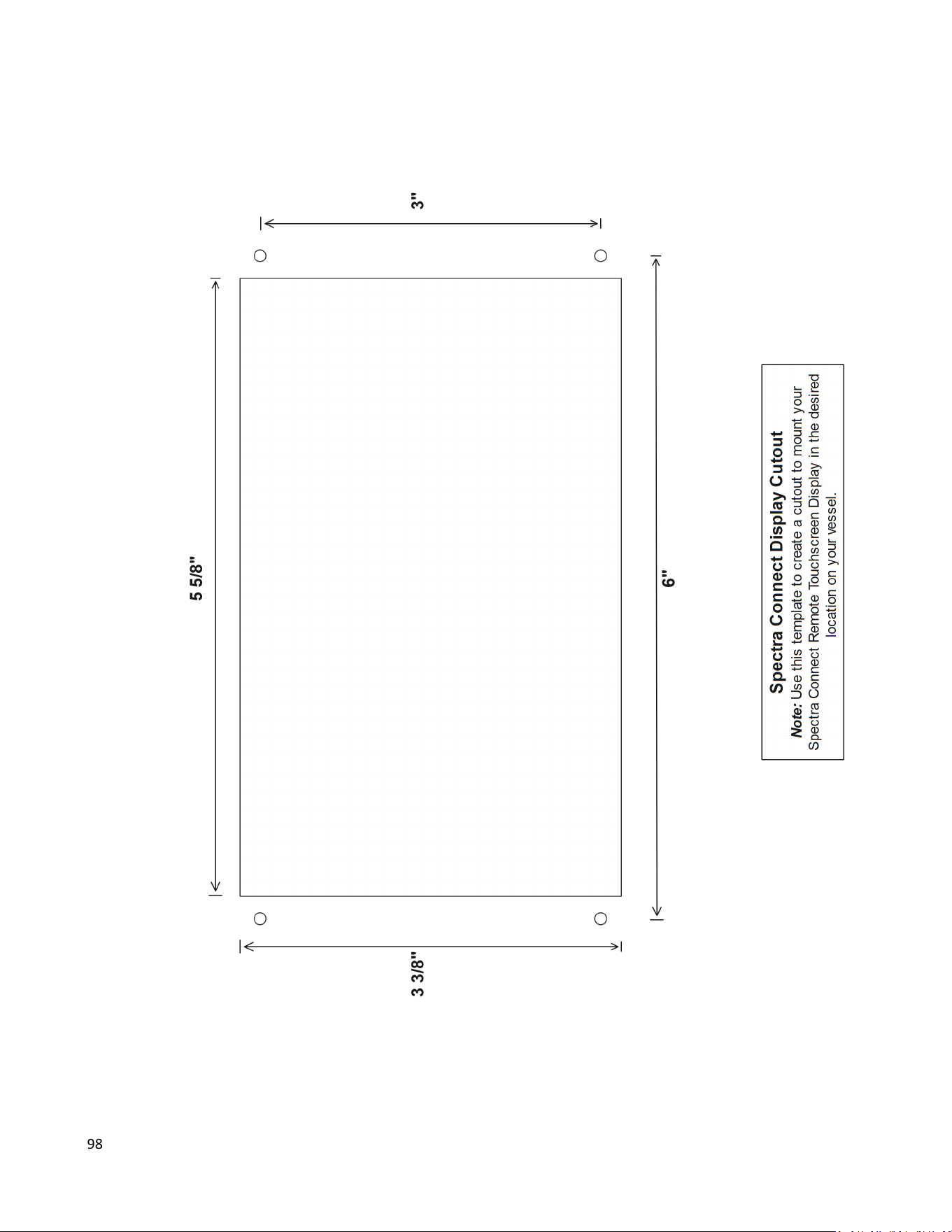
98

99