The 2N TELEKOMUNIKACE a.s. is a Czech manufacturer and supplier of
telecommunications equipment.
The product family developed by 2N TELEKOMUNIKACE a.s. includes GSM gateways,
private branch exchanges (PBX), and door and lift communicators. 2N
TELEKOMUNIKACE a.s. has been ranked among the Czech top companies for years
and represented a symbol of stability and prosperity on the telecommunications
market for almost two decades. At present, we export our products into over 120
countries worldwide and have exclusive distributors on all continents.
2N is a registered trademark of 2N TELEKOMUNIKACE a.s. Any product and/or other
®
names mentioned herein are registered trademarks and/or trademarks or brands
protected by law.
2N TELEKOMUNIKACE a.s. administers the FAQ database to help you quickly find
information and to answer your questions about 2N products and services. On www.
faq.2n.cz you can find information regarding products adjustment and instructions for
optimum use and procedures „What to do if...".
2N TELEKOMUNIKACE a.s. hereby declares that the 2N product complies with all
basic requirements and other relevant provisions of the 1999/5/EC directive. For the
full wording of the Declaration of Conformity see the CD-ROM (if enclosed) or our
website at www.2n.cz.
This device complies with part 15 of the FCC Rules. Operation is subject to the
following two conditions: (1) This device may not cause harmful interference, and (2)
this device must accept any interference received, including interference that may
cause undesired operation.

The 2N TELEKOMUNIKACE a.s. is the holder of the ISO 9001:2009 certificate. All
development, production and distribution processes of the company are managed by
this standard and guarantee a high quality, technical level and professional aspect of
all our products.

2N TELEKOMUNIKACE a.s., www.2n.cz 4/319
Content:
1. Product Overview
1.1 Components and Associated Products
1.2 Terms and Symbols
2. Description and Installation
2.1 Before You Start
2.2 Mechanical Installation
2.2.1 One Module Box
2.2.2 Two Module Box
2.2.3 More Two Module Boxes
2.2.4 Three Module Box
2.2.5 More Three Module Boxes
2.2.6 Tamper and I/O Modules
2.2.7 Module Dimensions
2.2.8 Example of Mounting Plate Installation
2.3 Electric Installation
2.4 Extending Module Connection
2.5 Completion
3. Function and Use
3.1 Configuration
3.2 Intercom Control as Viewed by External User
3.3 Touch Display Intercom Control As Viewed by External User
3.4 Intercom Control as Viewed by Internal User
3.5 Maintenance
3.6 Downloads
4. Technical Parameters
5. Supplementary Information
5.1 Troubleshooting
5.2 Directives, Laws and Regulations
5.3 General Instructions and Cautions


2N TELEKOMUNIKACE a.s., www.2n.cz 6/319
Basic Features
2N IP Verso
®
is an elegant and reliable intercom equipped with lots of useful
functions. Thanks to SIP support and compatibility with major brands of PBX
manufacturers, it can benefit from using VoIP networks. can be used as a 2N IP Verso
®
door or special purpose intercom for office buildings, residential areas and other
applications.
2N IP Verso
®
is a modular system: the user determines its configuration according to
the needs of the particular installation. Unlike other intercoms,
is not delivered as a compact unit. After choosing the installation mode 2N IP Verso
®
and particular modules, the user gets separate parts to be assembled using the
plug&play connections. This approach allows for unique individual combinations and
also leaves space for adding of additional modules later on.
Wide angle HD camera – allows the tenant to see the calling person on his or her
videophone or PC screen in high resolution. The camera itself is hidden behind a
darkened glass, so it is not visible. The intercom is equipped with night vision, which
automatically selects the night/day mode according to light.
Quick dial buttons – there are 146 quick dial buttons in total in multiple button
modules. For each button, up to three separate phone numbers plus substitute users
can be defined, which ensures that the called user is reached whenever needed. The
buttons are backlit with a clear mechanical response. The nametag surface is scratch
resistant.
Keypad – is a keypad module that allows the user to use the intercom as a code lock
and dial a phone number or phonebook position of the called user.
RFID card reader – the card reader module brings the access control functionality
according to the RFID card or keyfob. With the advanced features, other functions can
be RFID card controlled too.
Electric lock control – as part of the access system, the electrical lock can be
controlled by a code entered on the keypad or the called phone, with the RFID card,
via a PC application, etc. When necessary, more electrical outputs can be added.
Numerous parameters allow for a wide spectrum of applications.
Robustness – is designed as a vandal resistant intercom, which 2N IP Verso
®
withstands mechanical or weather conditions with no need to purchase extra
accessories.

2N TELEKOMUNIKACE a.s., www.2n.cz 7/319
Audio quality – using the automatic echo cancelling system, full duplex
communication is available at any time.
The installation of is very easy, all you have to do is assemble the 2N IP Verso
®
required parts and modules and attach the network cable. The modules are plug&play,
so there is no need to configure them manually. The intercom can be supplied from a
12 V DC power source, or using a PoE switch.
Use your PC with any internet browser to configure or apply the 2N IP Verso
®
2N
®
to configure extensive installations of multiple intercoms.Access Commander

2N TELEKOMUNIKACE a.s., www.2n.cz 8/319
Advantages of Use
Elegant design
Weather resistant
Various modes of installation (flush, surface, plasterboard)
Sensitive microphone and loud speaker
Both-way audio communication – acoustic echo cancellation
Integrated colour HD camera with wide-angle lense and hidden night vision
Selectable number of quick dial buttons with nametags and backlight
Optional numeric keypad with backlight
Option to have multiple modules of the same kind – for example, card reader for
both entering and leaving the building
Integrated switches of electric locks with wide setting options
Optional integrated RFID card reader module
PoE or 12 V DC power supply
Configuration using web interface or dedicated PC application
VoIP standard SIP 2.0 support
10 000 Phone Book positions
20 user time profiles
Video codecs (H.263, H.263+, H.264, MPEG-4, MJPEG)
Audio codecs (G.711, G.729, G.722, L16/16kHz)
HTTP server for configuration
SNTP client for time synchronisation
RTSP server for audio and video streaming, ONVIF compatible
SMTP client for email sending, Picture to Email feature
TFTP/HTTP client for automated firmware and configuration upgrade and
update
2N TELEKOMUNIKACE a.s., www.2n.cz 9/319
1.1 Components and Associated Products
Main Units
91551012N Part No.
Axis Part No. 01271-
001
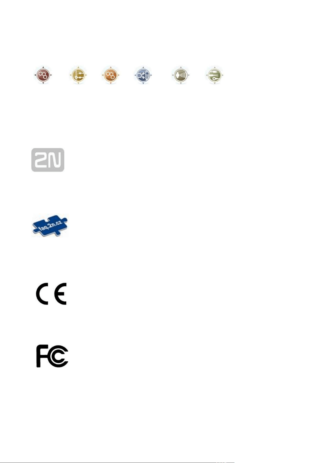
Main unit
There must be just one (with/without a camera) main unit in every
installation. The main unit installation requires two frame/box
positions; the other position, however, is left for additional module
installation.
9155101B2N Part No.
Axis Part No. 01272-
001
Main unit
There must be just one (with/without a camera) main unit in every
installation.The main unit installation requires two frame/box
positions; the other position, however, is left for additional module
installation.
We do not recommend to have the device installed where it is
exposed to direct sunlight
2N TELEKOMUNIKACE a.s., www.2n.cz 10/319
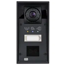
9155101C2N Part No.
Axis Part No. 01273-
001
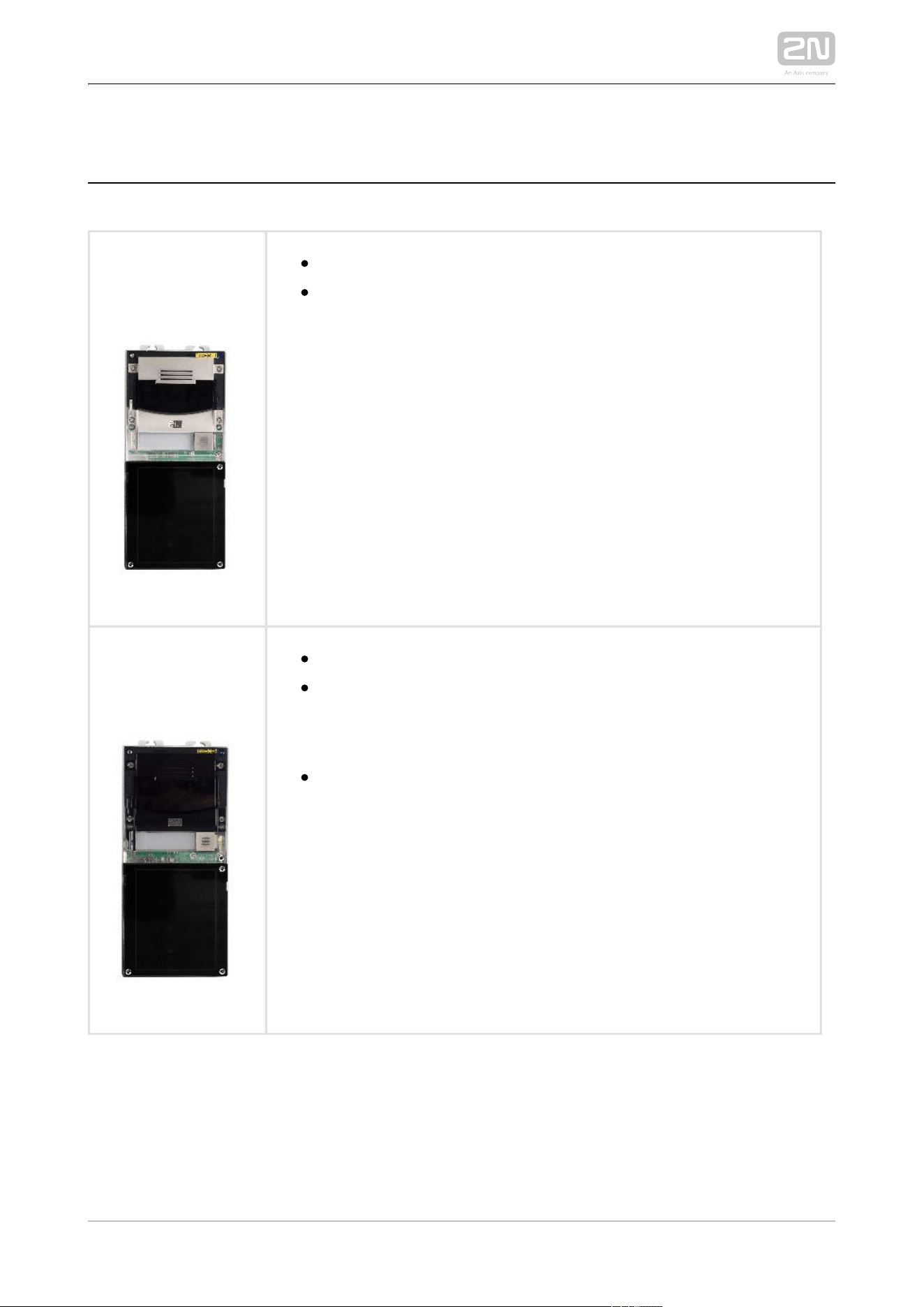
Main unit with camera
HD camera
There must be just one (with/without a camera) main unit in every
installation. The main unit installation requires two frame/box
positions; the other position, however, is left for additional module
installation.
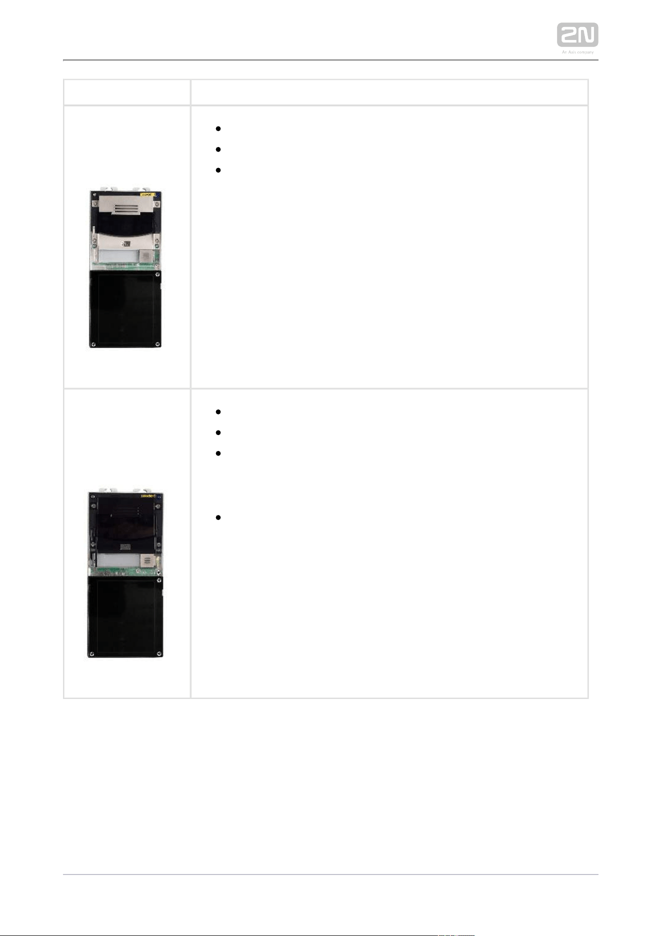
2N Part No.
9155101CB
Axis Part No. 01274-
001
Main unit
HD camera
There must be just one (with/without a camera) main unit in every
installation. The main unit installation requires two frame/box
positions; the other position, however, is left for additional module
installation.
We do not recommend to have the device installed where it is
exposed to direct sunlight.

2N TELEKOMUNIKACE a.s., www.2n.cz 11/319
Caution
There must be just one (with/without a camera) main unit in every
installation. The main unit installation requires two frame/box positions;
the other position, however, is left for additional module installation.
One blind module is supplied with the main unit.
2N TELEKOMUNIKACE a.s., www.2n.cz 12/319
Frames
91550112N Part No.
Axis Part No. 01278-001
Flush mounting frame
1-module
Covering frame for the 1-module brick/plasterboard
flush mounting box. The 1-module frame is used when
another module is added to the existing installation or
when the module is mounted to an extended
interconnecting cable for an outgoing reader, for
example. Remember to order the frame when you
order a 1-module flush mounting box, Part No. 9155014.
9155011B2N Part No.
Axis Part No. 01279-001
Flush mounting frame
1-module
Covering frame for the 1-module brick/plasterboard
flush mounting box. The 1-module frame is used when
another module is added to the existing installation or
when the module is mounted to an extended
interconnecting cable for an outgoing reader, for
example. Remember to order the frame when you
order a 1-module flush mounting box, Part No. 9155014.
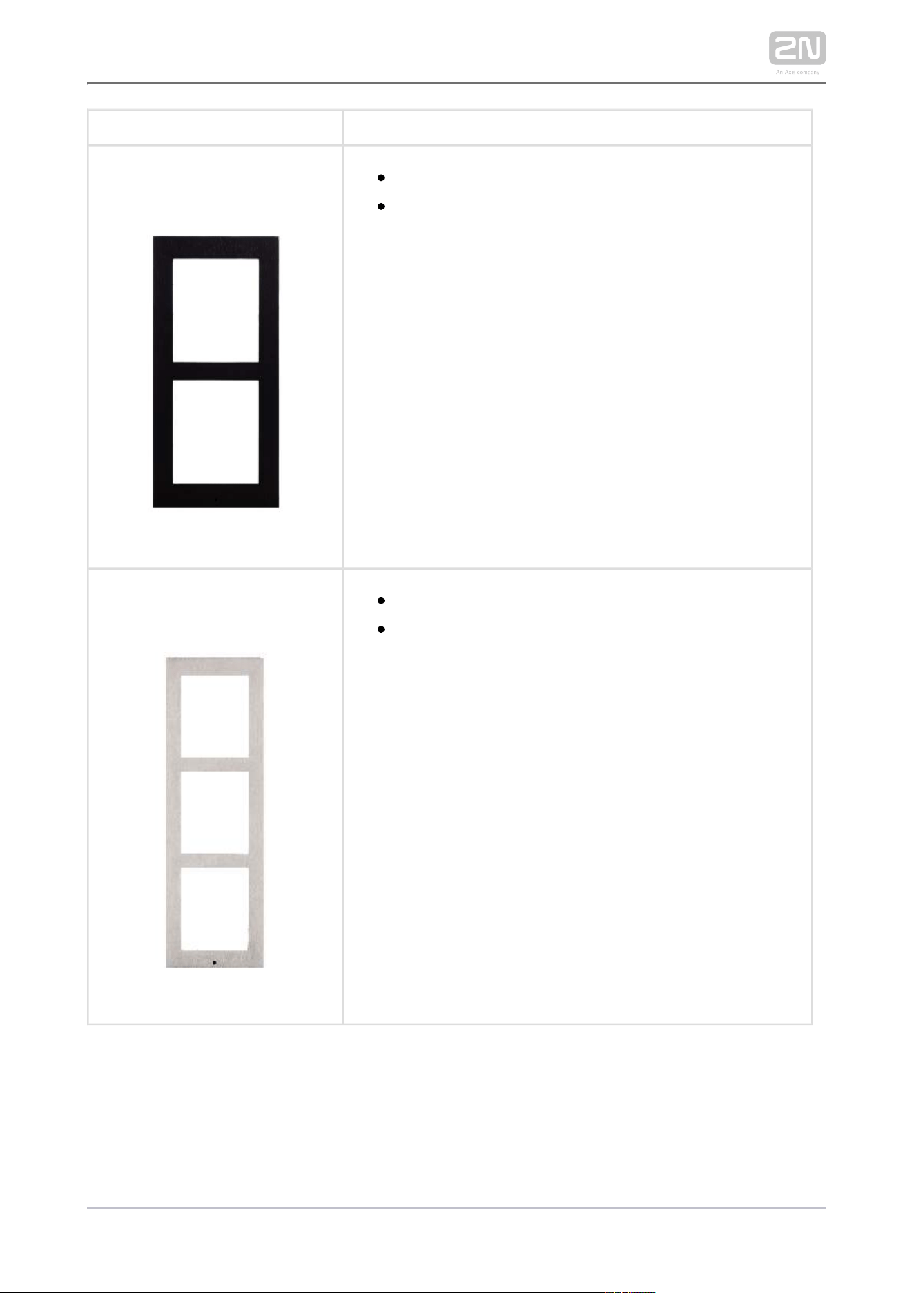
91550122N Part No.
Axis Part No. 01281-001
Flush mounting frame
2-modules
Covering frame for the 2-module brick/plasterboard
flush mounting box. Remember to order the frame
when you order a 2-module flush mounting box, Part
No. 9155015.
2N TELEKOMUNIKACE a.s., www.2n.cz 13/319
9155012B2N Part No.
Axis Part No. 01282-001
Flush mounting frame
2-modules
Covering frame for the 2-module brick/plasterboard
flush mounting box. Remember to order the frame
when you order a 2-module flush mounting box, Part
No. 9155015.
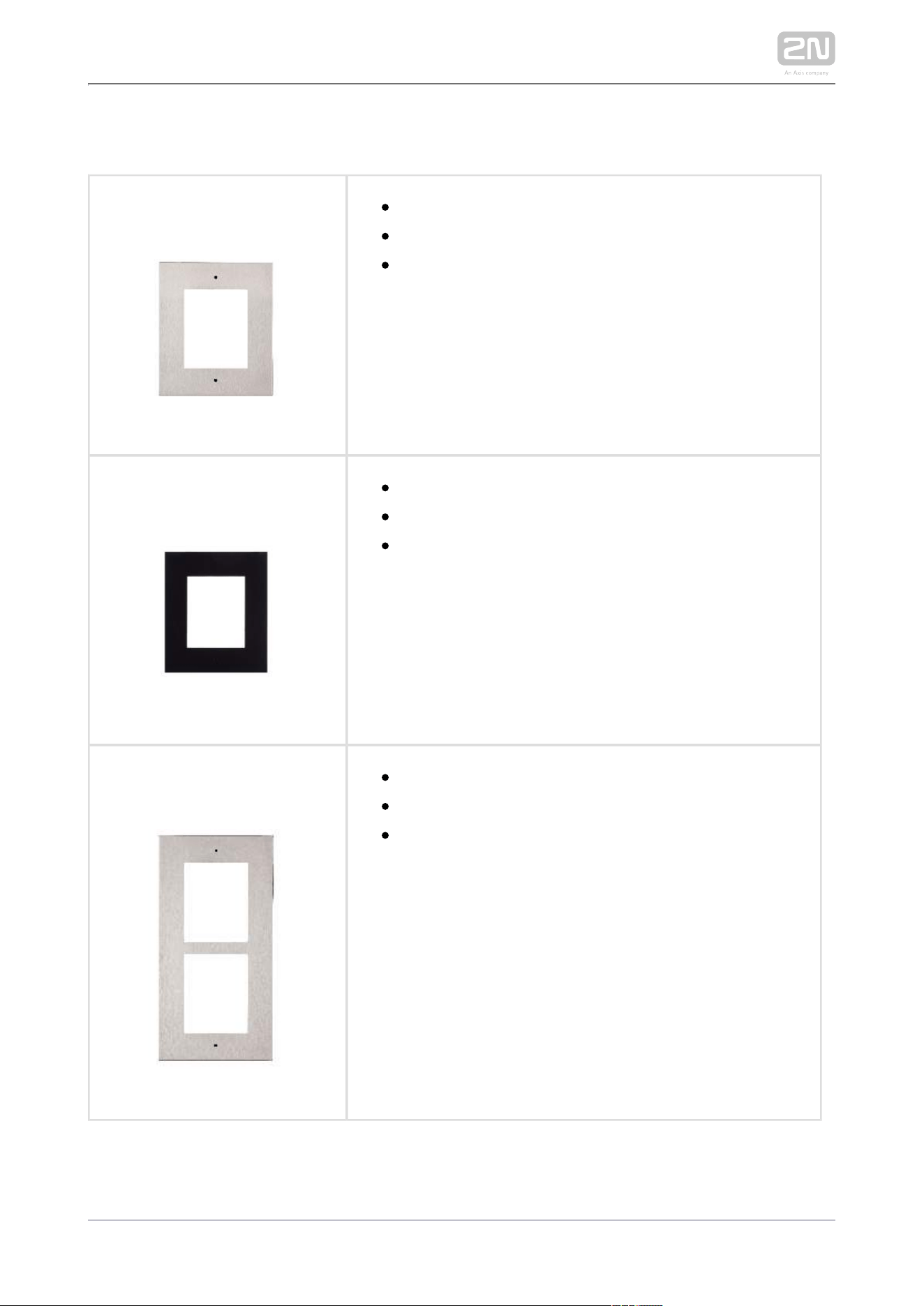
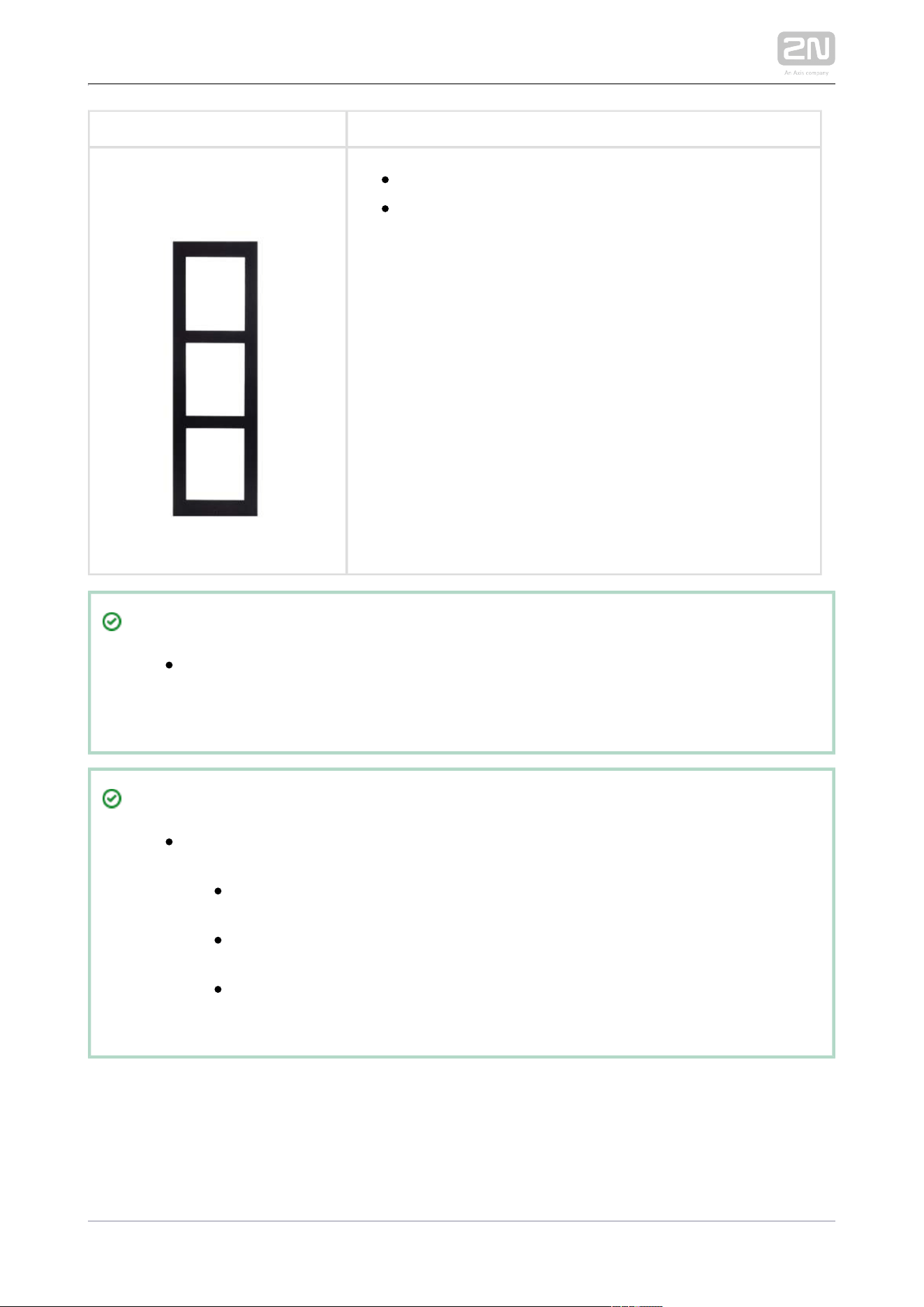
2N Part No. 9155013
Axis Part No. 01282-001
Flush mounting frame
3-modules
Covering frame for the 3-module brick/plasterboard
flush mounting box. Remember to order the frame
when you order a 3-module flush mounting box, Part
No. 9155016.
2N TELEKOMUNIKACE a.s., www.2n.cz 14/319
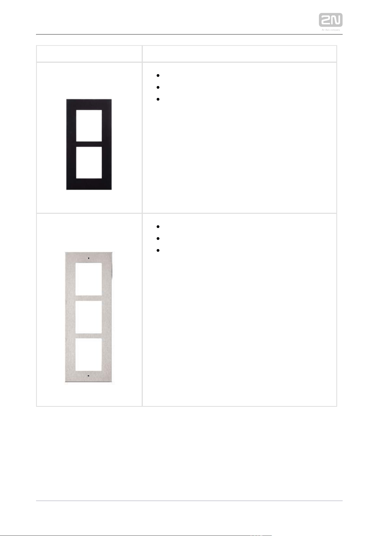
2N Part No. 9155013B
Axis Part No. 01283-001
Flush mounting frame
3-modules
Covering frame for the 3-module brick/plasterboard
flush mounting box. Remember to order the frame
when you order a 3-module flush mounting box, Part
No. 9155016.
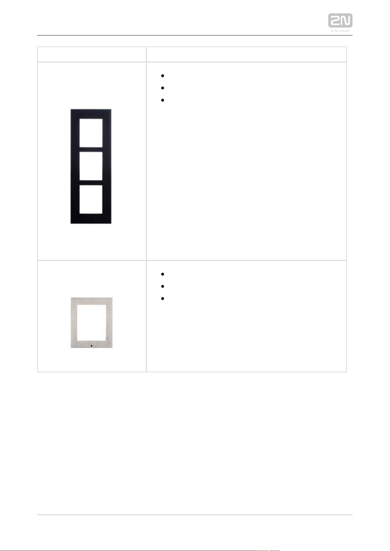
91550212N Part No.
Axis Part No. 01287-001
Surface mounting frame
1-module
The 1-module frame is used when another module is
added to the existing installation or when the module
is mounted to an extended interconnecting cable for
an outgoing reader, for example.
2N TELEKOMUNIKACE a.s., www.2n.cz 15/319
9155021B2N Part No.
Axis Part No. 01288-001
Surface mounting frame
1-module
The 1-module frame is used when another module is
added to the existing installation or when the module
is mounted to an extended interconnecting cable for
an outgoing reader, for example.
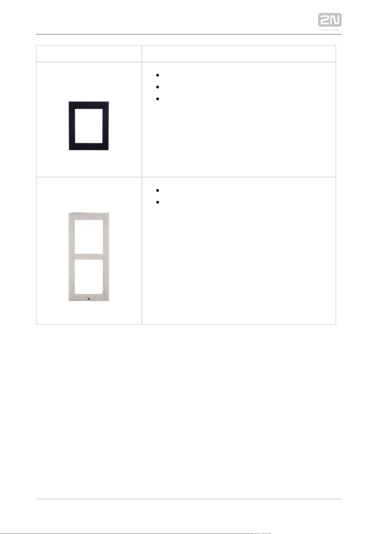
91550222N Part No.
Axis Part No. 01289-001
Surface mounting box
2-modules
2N TELEKOMUNIKACE a.s., www.2n.cz 16/319
9155022B2N Part No.
Axis Part No. 01290-001
Surface mounting box
2-modules
91550232N Part No.
Axis Part No. 01291-001
Surface mounting box
3-modules
2N TELEKOMUNIKACE a.s., www.2n.cz 17/319
9155023B2N Part No.
Axis Part No. 01292-001
Surface mounting box
3-modules
Tip
The 1-module frame is used when another module is added to the
existing installation or when the module is mounted to an extended
interconnecting cable for an outgoing reader, for example.
Tip
Be sure to order the covering frame for the flush or plasterboard
mounting box together with the flush mounting box.
1-module frame (Part No. ) – 1-module flush mounting box 9155011
(Part No. ) 9155014
2-module frame (Part No. ) – 2-module flush mounting box 9155012
(Part No. ) 9155015
3-module frame (Part No. ) – 3-module flush mounting box 9155013
(Part No. ) 9155016
2N TELEKOMUNIKACE a.s., www.2n.cz 18/319
Extending Modules
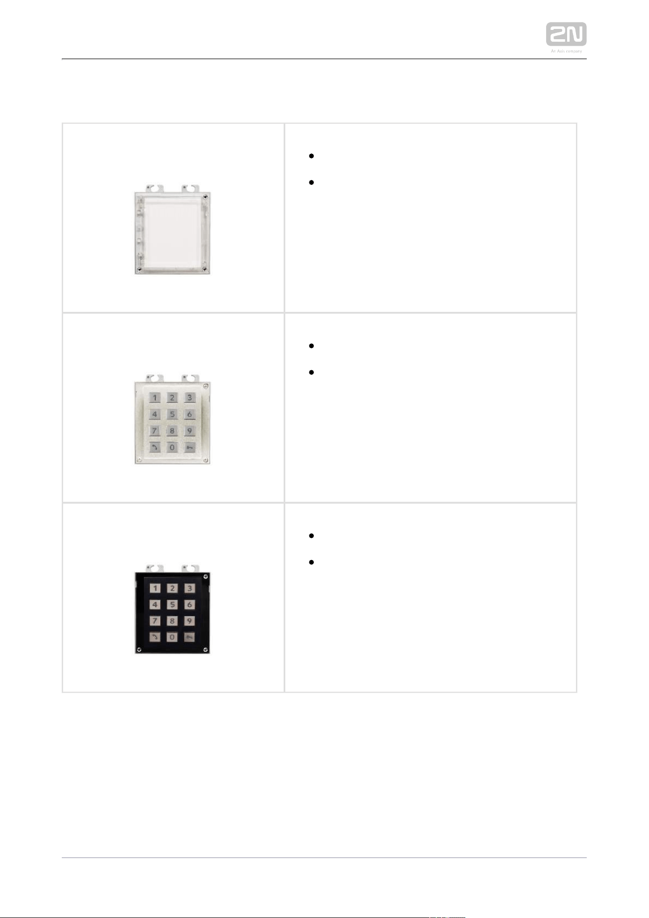
2N Part No. 9155030
Axis Part. No. 01252-001
2N IP Verso
®
– Info panel
The Infopanel module helps you place such
information into the intercom installation as
house number, opening hours and similar data.
The Infopanel backlight is software controlled.
2N Part No. 9155031
Axis Part No. 01253-001
2N IP Verso
®
– Keypad
The numeric keypad module helps you dial
users via their phonebook positions or phone
numbers, control the lock and use other code-
accessible functions. The keypad digits and
symbols are backlit.
2N Part No. 9155031B
Axis Part No. 01254-001
2N IP Verso
®
– Keypad
The numeric keypad module helps you dial
users via their phonebook positions or phone
numbers, control the lock and use other code-
accessible functions. The keypad digits and
symbols are backlit.
2N TELEKOMUNIKACE a.s., www.2n.cz 19/319
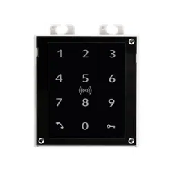
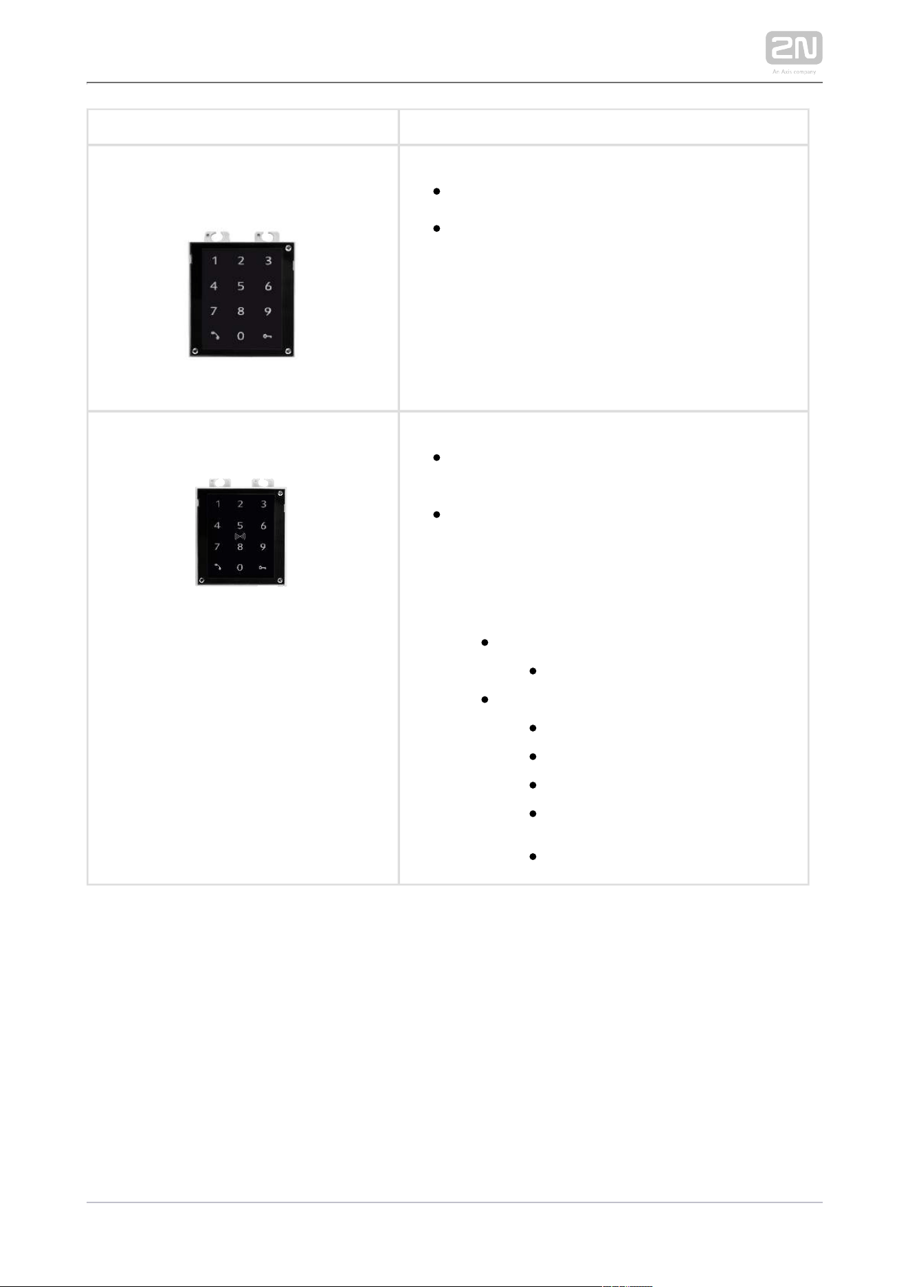
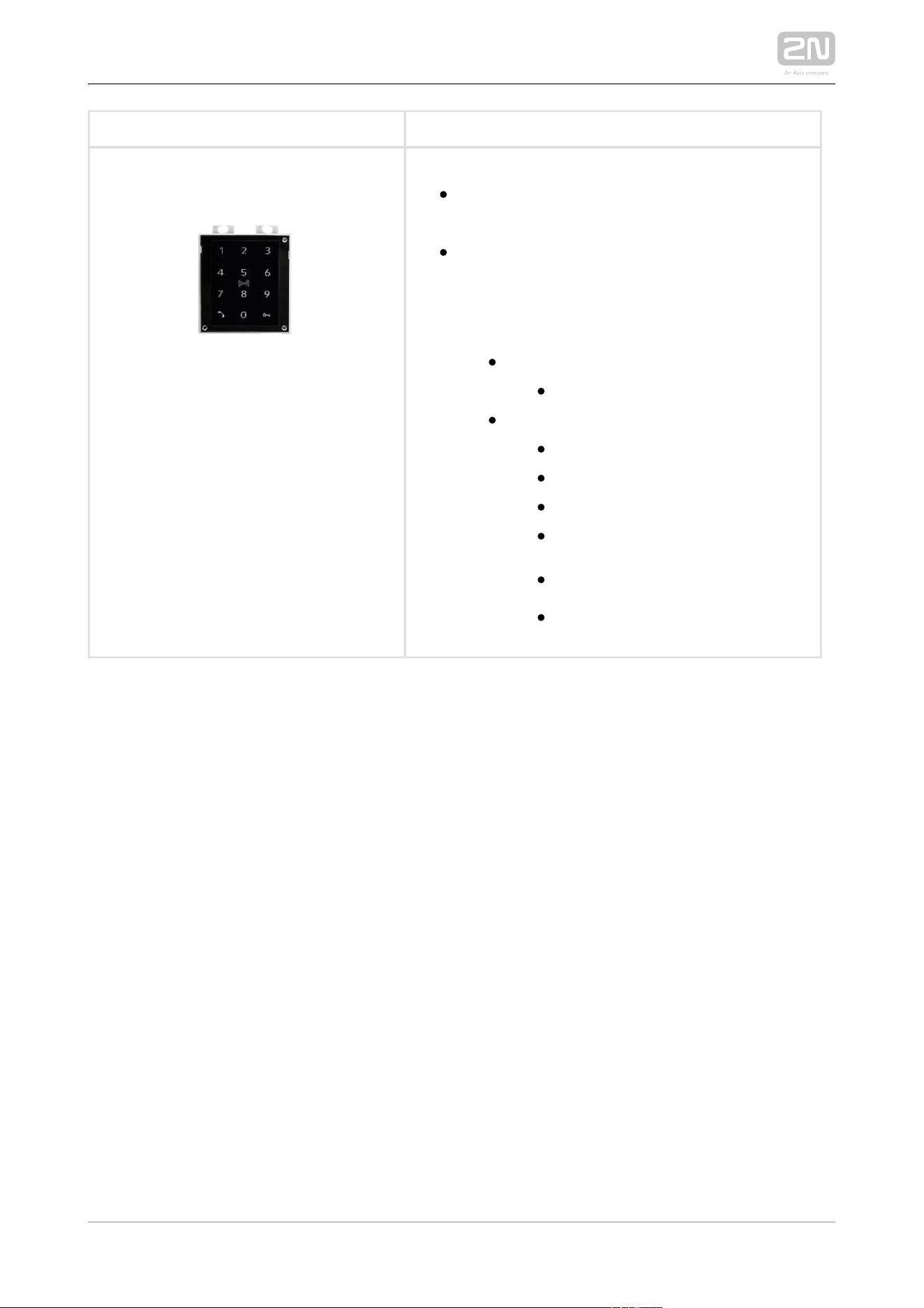
2N Part No. 9155047
Axis Part No. 01277-001
2N IP Verso
®
– Touch keypad
The numeric touch keypad module helps you
dial users via their phonebook positions or
phone numbers, control the lock and use other
code-accessible functions. The keypad digits
and symbols are backlit.
2N Part No. 9155081
2N IP Verso
®
– Touch keypad & RFID reader
125kHz, 13.56MHz, NFC
The touch keypad and card reader module
provides you with access control via
contactless cards or keyfobs. The module
supports the following 125 kHz and 13.56 MHz
cards or other carriers (only card serial number
is read):
125 kHz
EM4xxx
13.56 MHz
ISO14443A (Mifare, DESFire)
PicoPass (HID iClass)
FeliCa
ST SR(IX)
2N Mobile Key
®
2N TELEKOMUNIKACE a.s., www.2n.cz 20/319
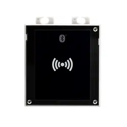
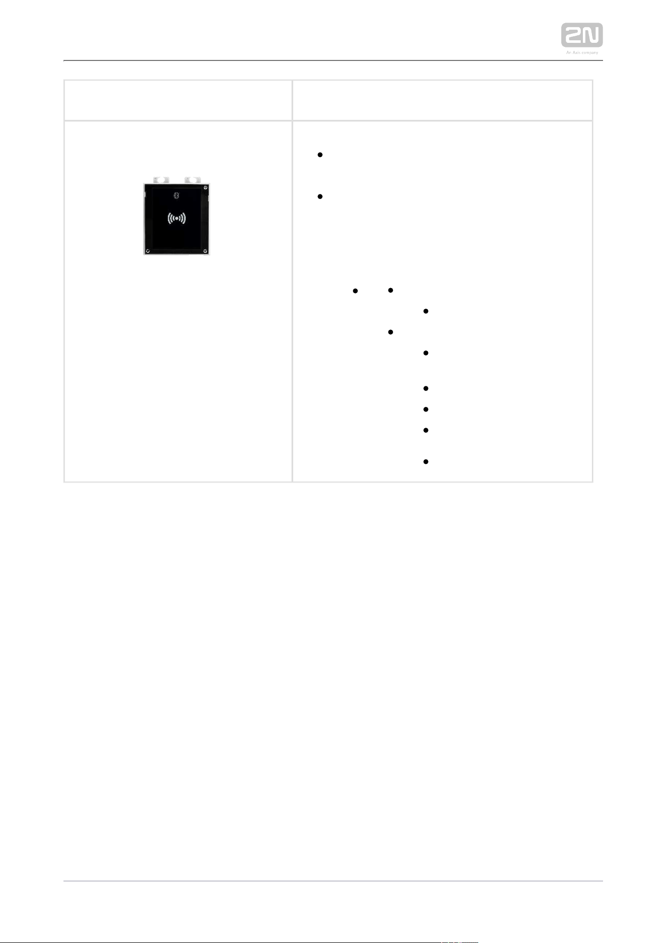
2N Part No. 9155082
2N IP Verso
®
– Bluetooth & RFID reader
125kHz, 13.56MHz, NFC
The bluetooth and card reader module
provides you with access control via
contactless cards or keyfobs. The module
supports the following 125 kHz and 13.56 MHz
cards or other carriers (only card serial number
is read):
125 kHz
EM4xxx
13.56 MHz
ISO14443A (Mifare,
DESFire)
PicoPass (HID iClass)
FeliCa
ST SR(IX)
2N Mobile Key
®
2N TELEKOMUNIKACE a.s., www.2n.cz 21/319
2N Part No. 9155083
2N IP Verso
®
– Touch keypad & RFID reader
125kHz, secured 13.56MHz, NFC
The touch keypad card reader module provides
you with access control via contactless cards
or keyfobs. The module supports the following
125 kHz and 13.56 MHz cards or other carriers
(only card serial number is read):
125 kHz
EM4xxx
13.56 MHz
ISO14443A (Mifare, DESFire)
PicoPass (HID iClass)
FeliCa
ST SR(IX)
2N Mobile Key
®
HID SE (Seos, iClass SE, Mifare
SE)
2N TELEKOMUNIKACE a.s., www.2n.cz 22/319
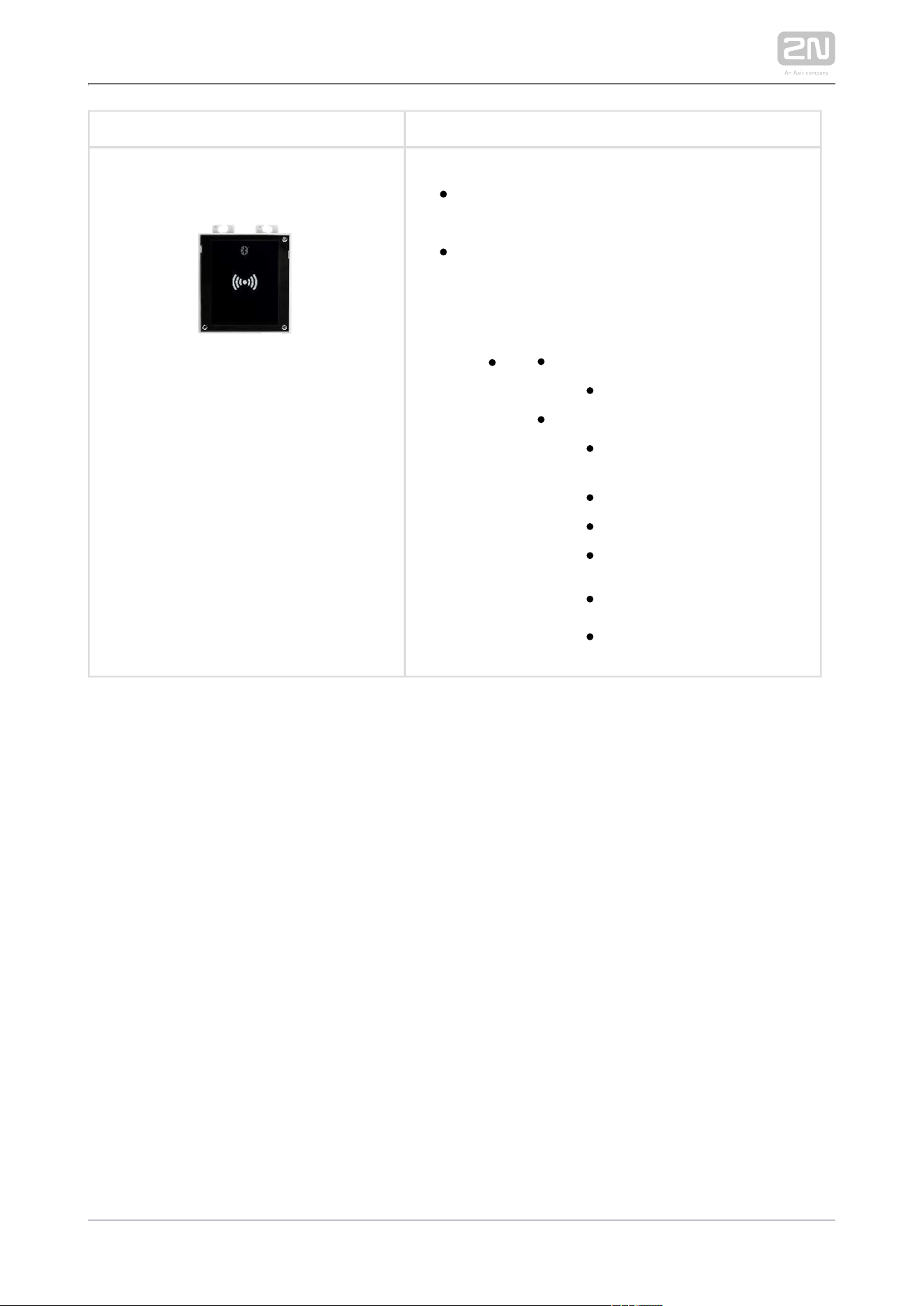
2N Part No. 9155084
2N IP Verso
®
– Bluetooth & RFID reader
125kHz, secured 13.56MHz, NFC
The bluetooth card reader module provides
you with access control via contactless cards
or keyfobs. The module supports the following
125 kHz and 13.56 MHz cards or other carriers
(only card serial number is read):
125 kHz
EM4xxx
13.56 MHz
ISO14443A (Mifare,
DESFire)
PicoPass (HID iClass)
FeliCa
ST SR(IX)
2N Mobile Key
®
HID SE (Seos, iClass SE,
Mifare SE)
2N TELEKOMUNIKACE a.s., www.2n.cz 23/319
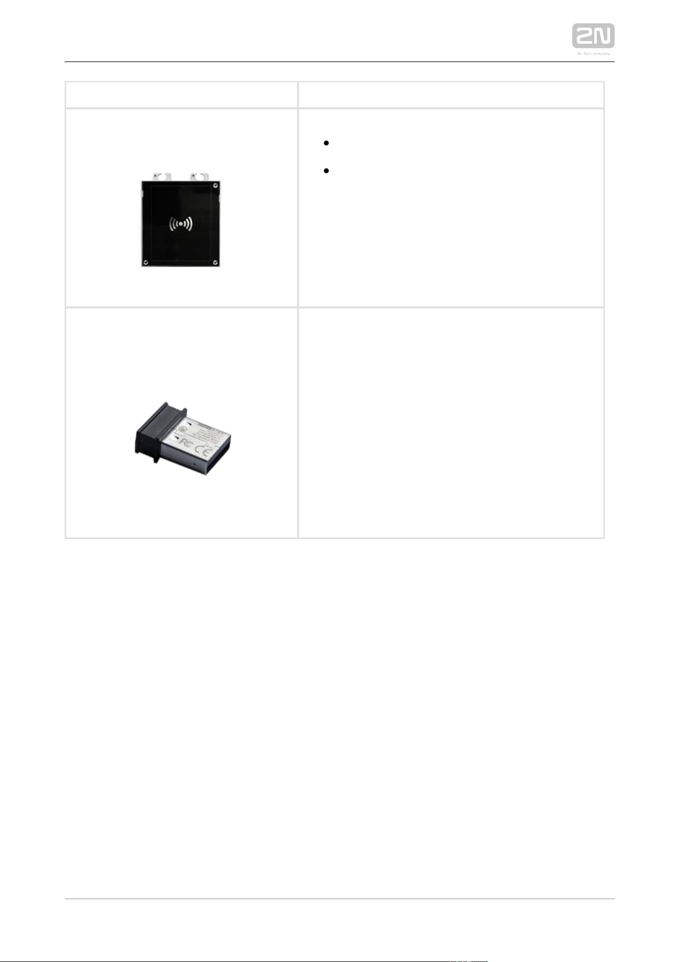
2N Part No. 9155032
Axis Part No. 01255-001
2N IP Verso
®
– RFID Reader, 125 kHz
The card reader module provides you with
access control via contactless cards or
keyfobs. The module supports the 125 kHz
EM4xxx cards.
2N Part No. 9137422E
Axis Part No. 01402-001
2N IP external Bluetooth reader (USB interface)
®
An external Bluetooth reader connecting to your
computer via USB.
It can be used to pair new users who want to use their
smartphones and application for 2N Mobile Key
®
access to controlled areas.
An USB driver is required for the external reader to
work properly.
2N TELEKOMUNIKACE a.s., www.2n.cz 24/319
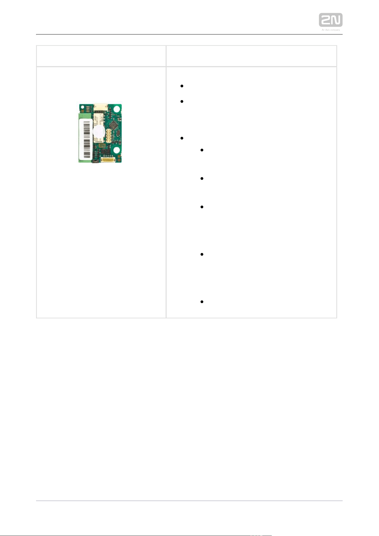
2N Part No. 9155034
Axis Part No. 01257-001
2N IP Verso
®
– I/O
The module provides logical inputs and
outputs for sensor integration or door control.
The module is installed under another module, i.
e. needs no separate position.
Inputs and outputs
RELAY1 – RELAY1 terminals with
accessible 30 V / 1 A AC/DC NO/NC
contact
RELAY2 – RELAY2 terminals with
accessible 30 V / 1 A AC/DC NO/NC
contact
IN1 – IN1 terminals for input in passive/
active mode (−30 V to +30 V DC)
OFF = open OR U > 1.5 V
IN
ON = closed contact OR U < 1.5 V
IN
IN2 – IN2 terminals for input in passive
/active mode (−30 V to +30 V DC)
OFF = open OR U > 1.5 V
IN
ON = closed contact OR U < 1.5 V
IN
TAMPER – Tamper switch (9155038)
input
2N TELEKOMUNIKACE a.s., www.2n.cz 25/319
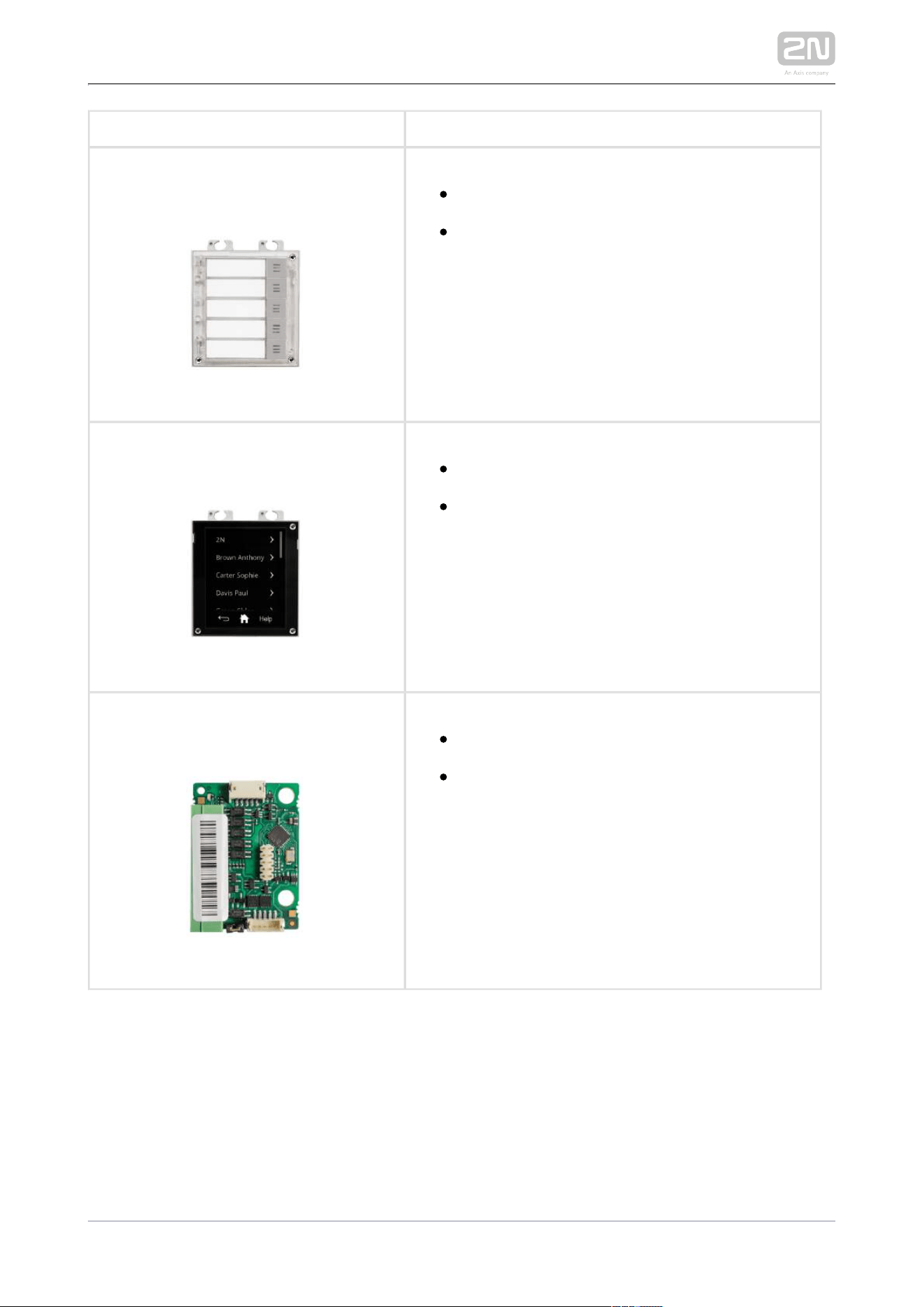
2N Part No. 9155035
Axis Part No. 01258-001
2N IP Verso
®
– 5 buttons
A module with 5 mechanical quick dial buttons.
The buttons are backlit and can include
nametags.
2N Part No. 9155036
Axis Part No. 01275-001
– Touch Display2N IP Verso
®
Touchscreen module allowing visitors to dial
users in smartphone-like way. In addition to
structured phonebook features also a keypad.
2N Part No. 9155037
Axis Part No. 01259-001
2N IP Verso
®
– Wiegand
The module helps you interconnect your
system with other systems via the Wiegand
interface. The module is installed under another
module, i.e. needs no separate position.
2N TELEKOMUNIKACE a.s., www.2n.cz 26/319
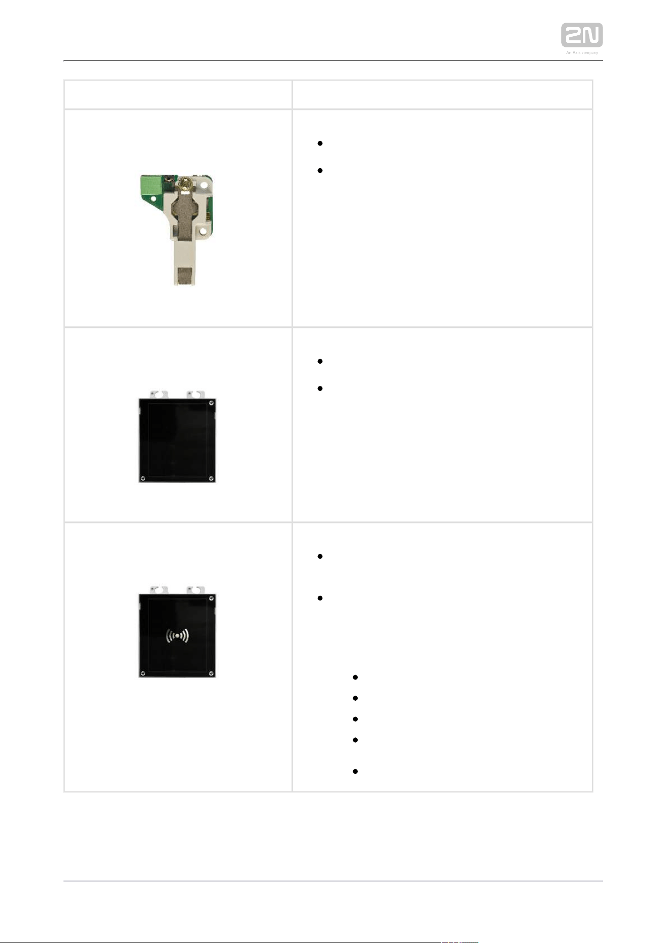
2N Part No. 9155038
Axis Part No. 01260-001
2N IP Verso
®
– Tamper switch
The module secures your system against
tampering by detecting intercom opening or
top frame removing. The module is installed on
a special place and needs no separate position.
2N Part No. 9155039
Axis Part No. 01261-001
2N IP Verso
®
– Blind Panel
One blind panel module is supplied with the
main unit.
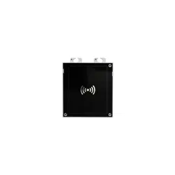
2N Part No. 9155040
Axis Part No. 01262-001
2N IP Verso
®
– RFID Reader NFC support,
13.56 MHz
The card reader module provides you with
access control via contactless cards or
keyfobs. The module supports the following
13.56 MHz cards or other carriers (only card
serial number is read):
ISO14443A (Mifare, DESFire)
PicoPass (HID iClass)
FeliCa
ST SR(IX)
2N Mobile Key
®
2N TELEKOMUNIKACE a.s., www.2n.cz 27/319
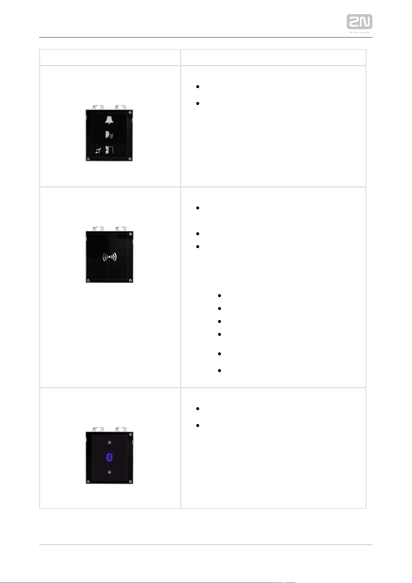
2N Part No. 9155041
Axis Part No. 01263-001
2N IP Verso
®
– Induction loop
The induction loop module is used to transmit
an audio signal directly into a hearing aid via a
magnetic field.
2N Part No. 9155086
Axis Part No. 01264-001
2N IP Verso
®
– Secured RFID Card Reader NFC
support, 13.56 MHz
Compatible with firmware 2.13 and higher.
The card reader module provides you with
access control via contactless cards or
keyfobs. The module supports the following
13.56 MHz cards or other carriers (optionally
card serial number or PAC ID is read):
ISO14443A (Mifare, DESFire)
PicoPass (HID iClass)
FeliCa
ST SR(IX)
2N Mobile Key
®
HID SE (Seos, iClass SE, Mifare SE)
2N Part No. 9155046
Axis Part No. 01266-001
2N IP Verso
®
– Bluetooth reader
The Bluetooth reader is used for reading users
secure ID numbers from the application of
smart phones Android and iOS.
2N TELEKOMUNIKACE a.s., www.2n.cz 28/319
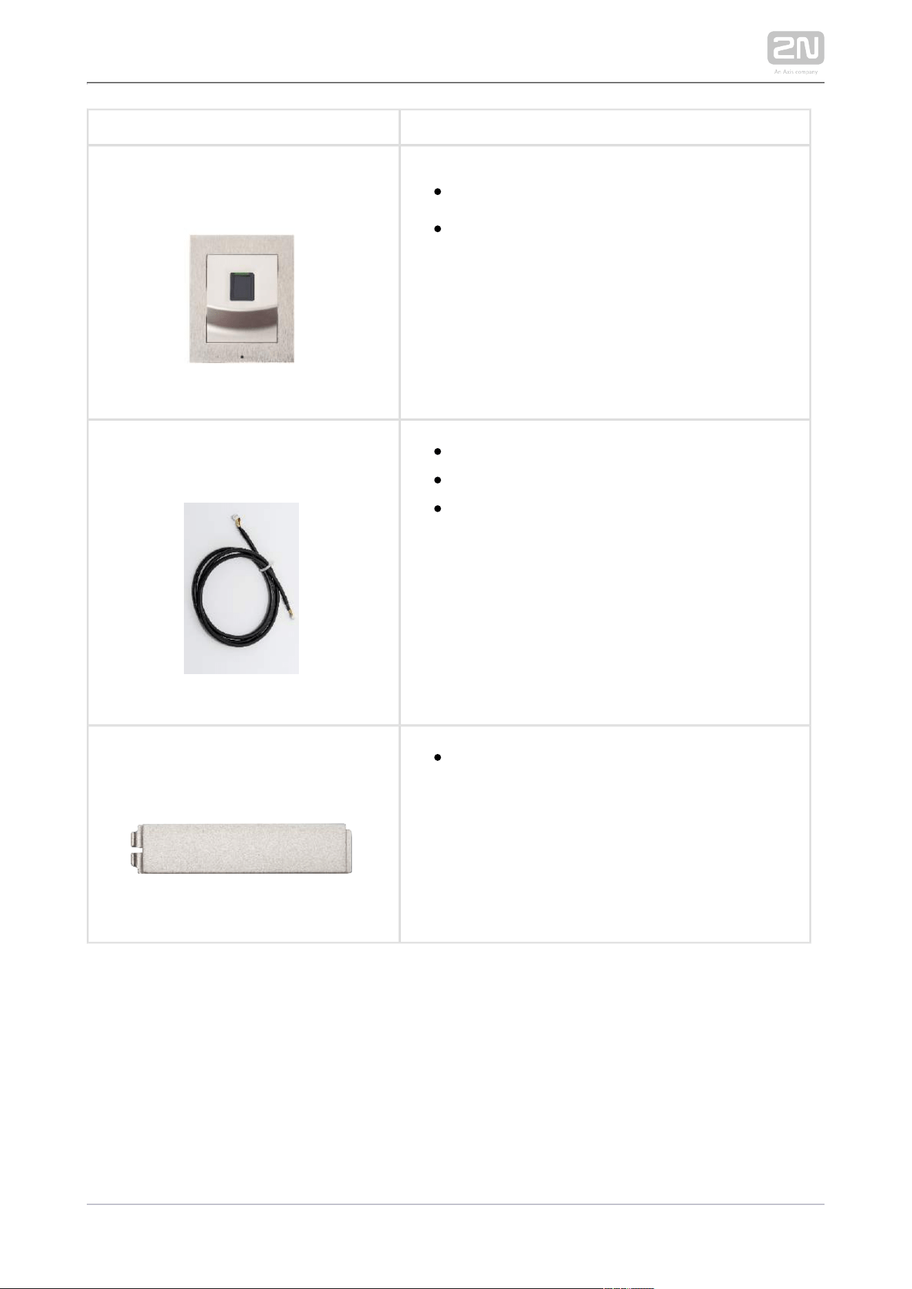
2N Part No. 9155045
Axis Part No. 01276-001
2N IP Verso
®
– Fingerprint reader
The Fingerprint reader is used for verification
of human fingers for access control and
intercom control.
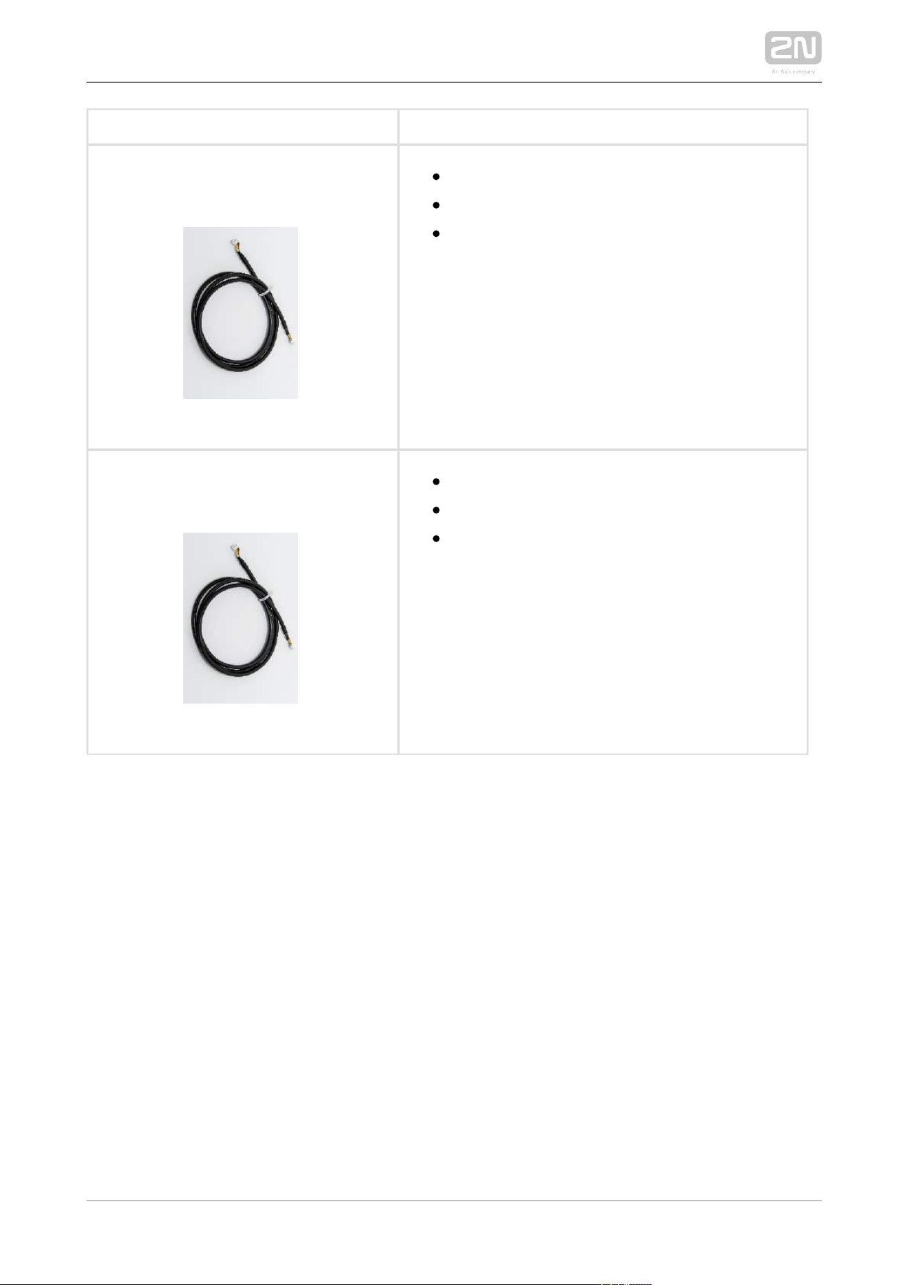
2N Part No. 9155050
Axis Part No. 01267-001
1 m extension cable
Only one extension cable allowed.
Maximum bus length is 7 m.
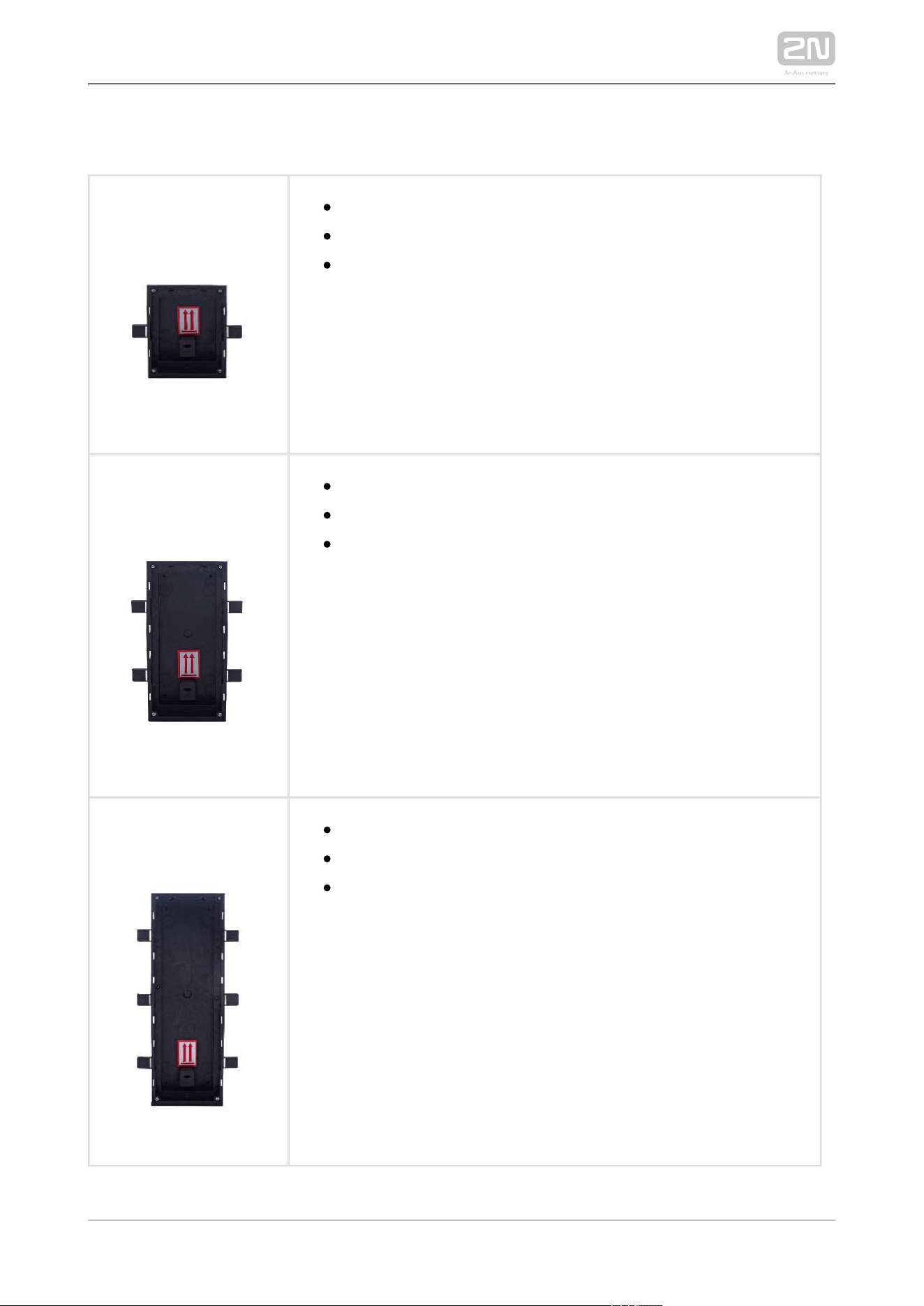
2N Part. No. 9155051
Axis Part No. 01270-001
Blind button
2N TELEKOMUNIKACE a.s., www.2n.cz 29/319
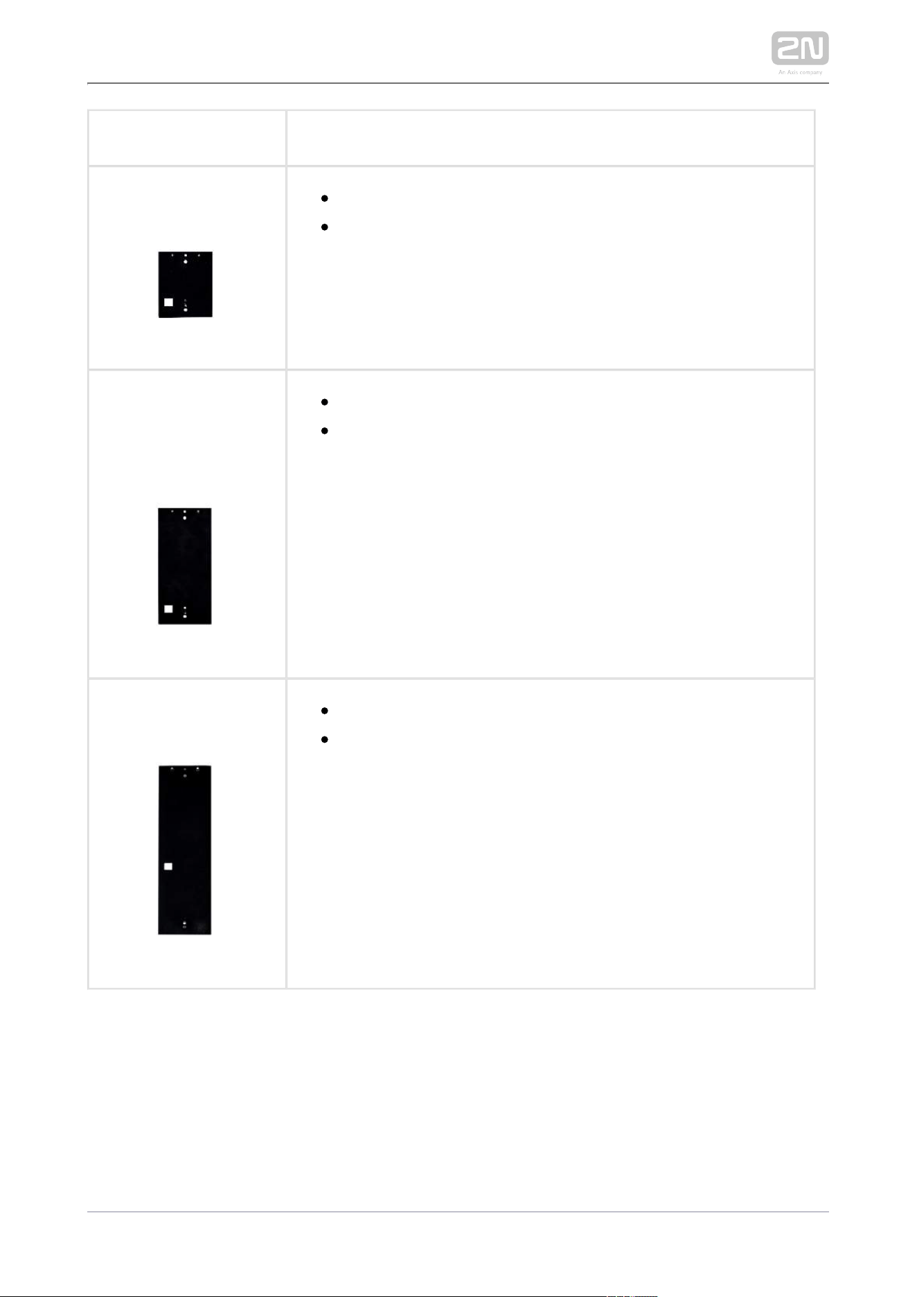
2N Part No. 9155054
Axis Part No. 01268-001
3 m extension cable
Only one extension cable allowed.
Maximum bus length is 7 m.
2N Part No. 9155055
Axis Part No. 01269-001
5 m extension cable
Only one extension cable allowed.
Maximum bus length is 7 m.
2N TELEKOMUNIKACE a.s., www.2n.cz 30/319
Mounting Accessories
91550142N Part No.
Axis Part No. 01284-001
Flush mounting box
1 module
Designed for flush or plasterboard mounting of 1-module sets
and delivered including accessories for multiple box assemblies
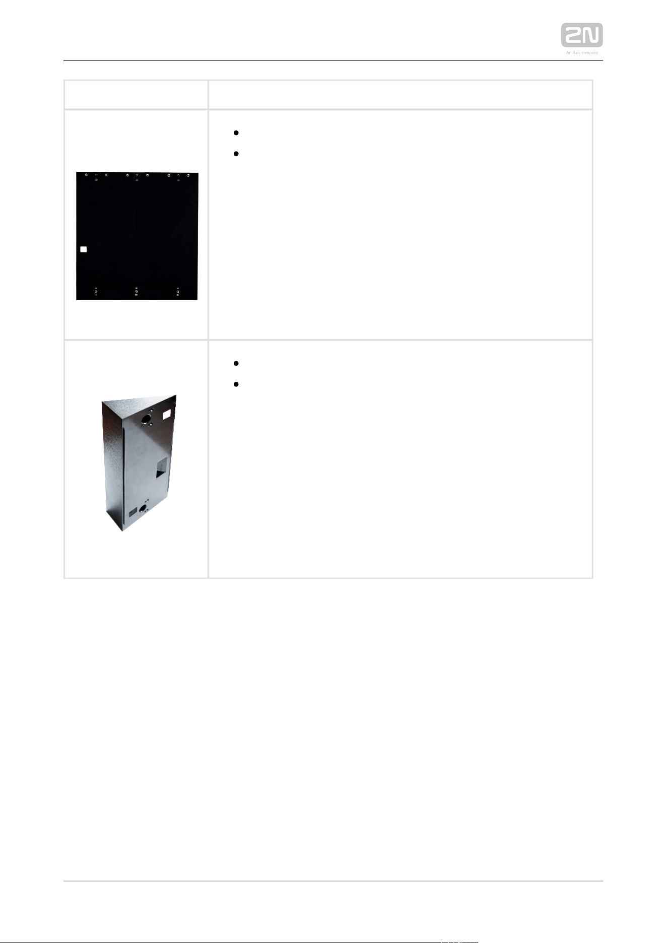
91550152N Part No.
Axis Part No. 01285-001
Flush mounting box
2 modules
Designed for flush or plasterboard mounting of 2-module sets
and delivered including accessories for multiple box assemblies
2N Part No. 9155016
Axis Part No. 01286-001
Flush mounting box
3 modules
Designed for flush or plasterboard mounting of 3-module sets
and delivered including accessories for multiple box assemblies
2N TELEKOMUNIKACE a.s., www.2n.cz 31/319
2N Part No. 9155061
Axis Part No. 01293-001
Backplate 1 module
For glass or uneven surface installation
2N Part No. 9155062
Axis Part No. 01294-001
Backplate 2 modules
For glass or uneven surface installation
2N Part No. 9155063
Axis Part No. 01295-001
Backplate 3 modules
For glass or uneven surface installation

2N TELEKOMUNIKACE a.s., www.2n.cz 32/319
2N Part No. 9155064
Axis Part No. 01296-001
Backplate 2 (w) x 2 (h) modules
For glass or uneven surface installation
2N Part No. 9155065
Axis Part No. 01297-001
Backplate 3 (w) x 2 (h) modules
For glass or uneven surface installation
2N Part No. 9155066
Axis Part No. 01298-001
Backplate 2 (w) x 3 (h) modules
For glass or uneven surface installation
2N TELEKOMUNIKACE a.s., www.2n.cz 33/319
2N Part No. 9155067
Axis Part No. 01299-001
Backplate 3 (w) x 3 (h) modules
For glass or uneven surface installation
Part No. 9155072
Wedge backplate
25 gradient mounting backplate°
Choose the proper frame and, if necessary, mounting box type depending on your
particular installation needs. is designed for outdoor 2N IP Verso
®
2N IP Verso
®
applications and requires no additional roof.
2N TELEKOMUNIKACE a.s., www.2n.cz 34/319
Internal Units and Accessories
Part Nos:
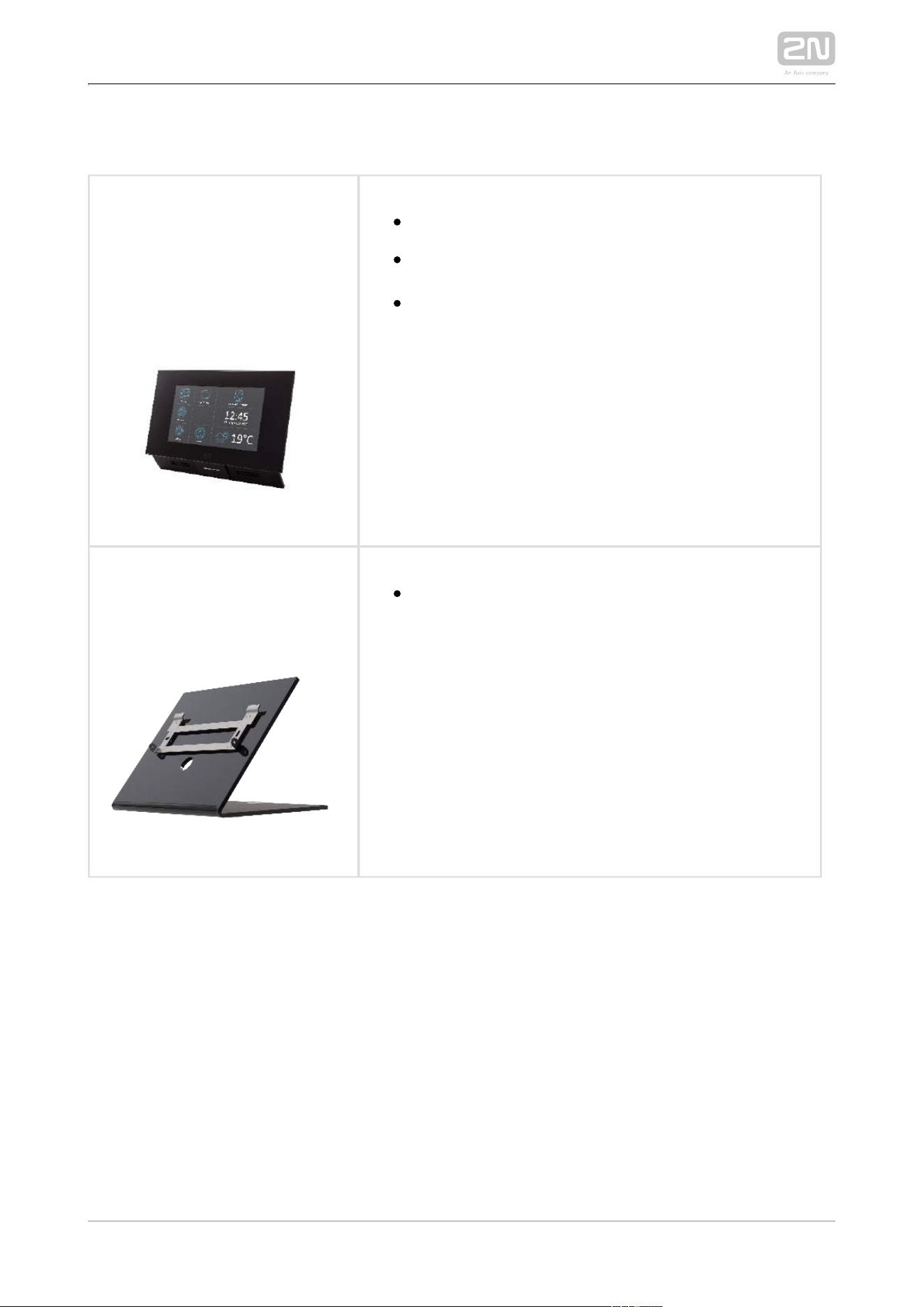
2N Part No. 91378365
Axis Part No. 01416-001
913783662N Part No.
01419-001Axis Part No.
2N Indoor Touch
®
– black
WiFi version (second Part No.)
The elegant internal touch panel, , 2N Indoor Touch
®
is suitable for all intercoms. On the panel’s 2N IP
display you can you find out who is at the door, but
also start a conversation with the visitor, open the
lock or turn on the light in the entrance hall.
Part No.:
913783822N Part No.
01425-001Axis Part No.
2N Indoor Touch
®
desk stand black
2N TELEKOMUNIKACE a.s., www.2n.cz 35/319
Part Nos:
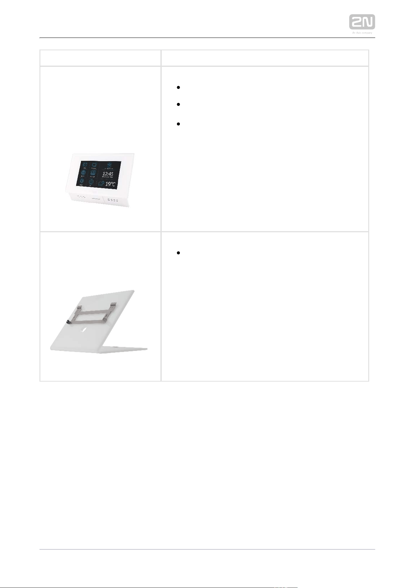
91378365WH2N Part No.
01417-001Axis Part No.
91378366WH2N Part No.
01420-001Axis Part No.
2N Indoor Touch
®
– white
WiFi version (second part no.)
The elegant internal touch panel, , 2N Indoor Touch
®
is suitable for all intercoms. On the panel’s 2N IP
display you can you find out who is at the door, but
also start a conversation with the visitor, open the
lock or turn on the light in the entrance hall.
Part No.:
91378382W2N Part No.
01426-001Axis Part No.
2N Indoor Touch
®
desk stand white
2N TELEKOMUNIKACE a.s., www.2n.cz 36/319
VoIP Phones
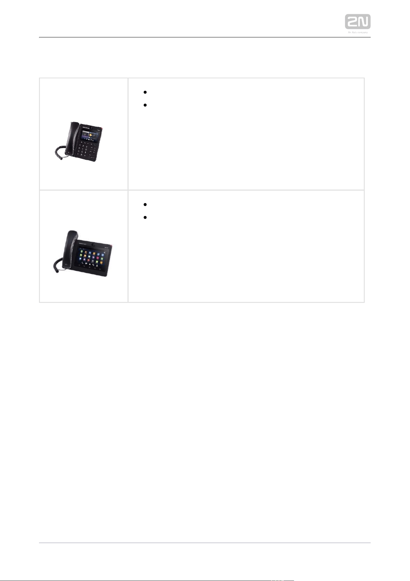
913783572N Part No.
Axis Part No. 01422-001
Grandstream GXV3240 VoIP video telephone
GXV3240 is the successor to the popular GXV3140 model,
which allows for comfortable video calls in the IP network.
Touchscreen and keypad control.
913783582N Part No.
Axis Part No. 01421-001
Grandstream GXV3275 VoIP telephone
GXV3275 is the successor to the popular GXV3175 model,
which allows for comfortable video calls in the IP network.
Touchscreen control.
2N TELEKOMUNIKACE a.s., www.2n.cz 37/319
Electric Locks
932071E2N Part No.
BEFO 11211
12 V / 230 mA DC
low consumption
932081E2N Part No.
BEFO 11221 with momentum pin
12 V / 230 mA DC
low consumption
For opening of the lock a short electrical impuls is sufficient,
which unlocks the lock. Lock is then open until someone closes
the door.
932091E2N Part No.
BEFO 11211MB with mechanical blocking
12 V / 230 mA DC
low consumption
Enables mechanically close or open the lock. When opened,
the lock is open all the time. When closed, it behaves as
standart electrical lock.
2N TELEKOMUNIKACE a.s., www.2n.cz 38/319
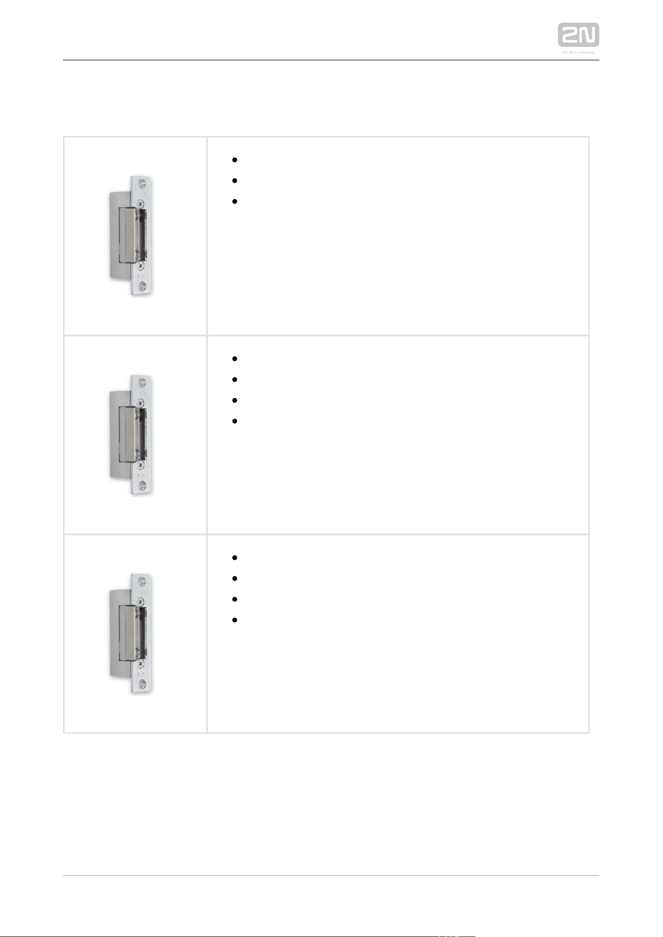
2N Part No. 932061E
BEFO 211211 door signalling, low consumption
12 V / 230 mA
A regular lock with a built-in contact to indicate whether the
door is open or closed.
2N Part No. 932072E
BEFO 31211 fail-safe
12 V / 170 mA DC
The failsafe lock is closed when electricity is switched on.
When electricity is interrupted, the lock is opened.
2N Part No. 932062E
BEFO 321211 fail-safe, door signalling
12 V / 170 mA
The failsafe lock is closed when electricity is switched on.
When electricity is interrupted, the lock is opened.
It contains a built-in contact to indicate whether the door is
open or closed.

2N TELEKOMUNIKACE a.s., www.2n.cz 40/319
Power Supply
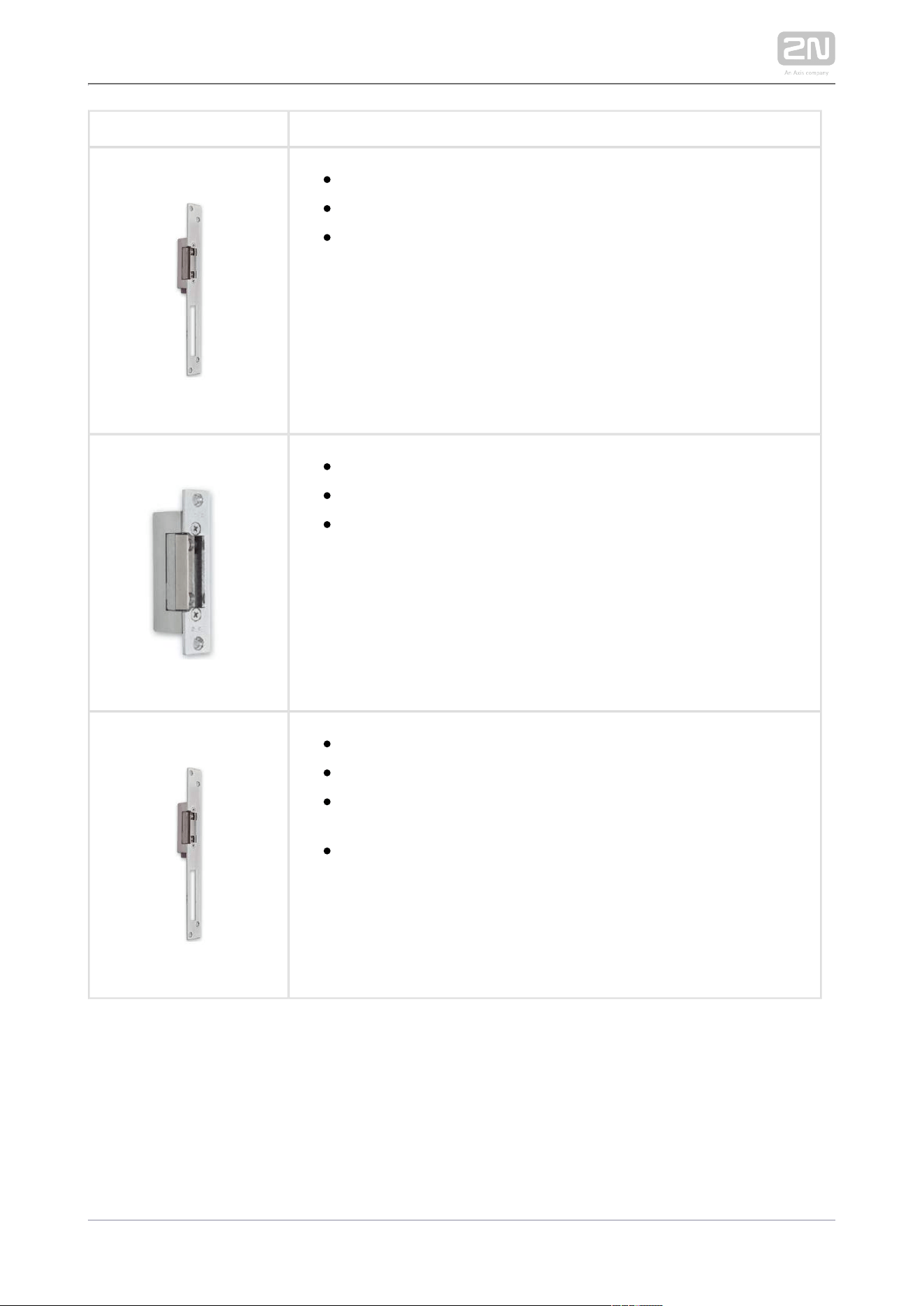
Part Nos:
2N Part No.91378100,
Axis Part no. 01394-
001
2N Part No.
91378100E
2N Part No.
91378100US, Axis
Part no. 01403-001
PoE injector – without cable (91378100)
PoE injector – with EU cable (91378100E)
PoE injector – with US cable (91378100US)
For power supply of intercom via ethernet cable when PoE switch
is not available.
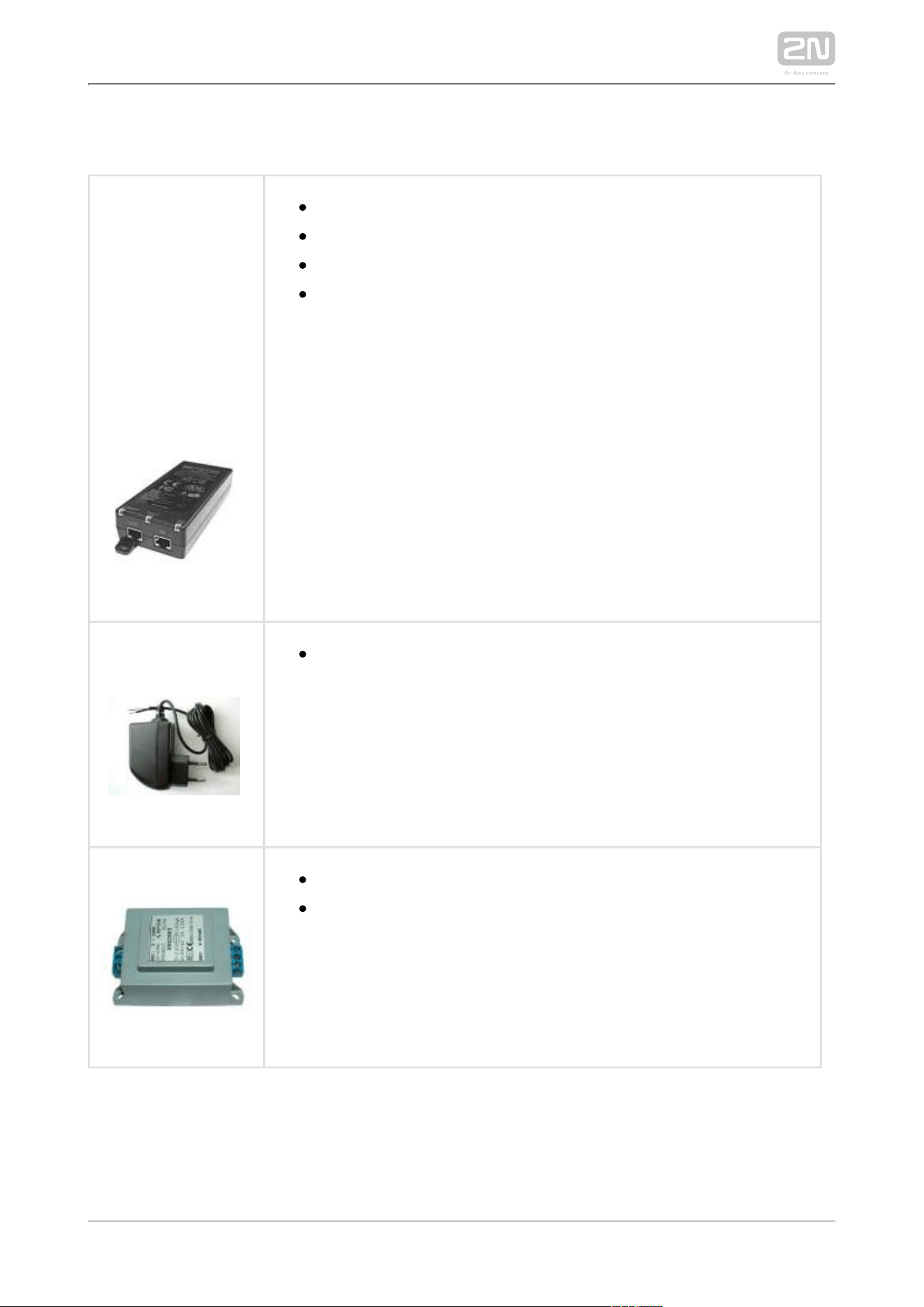
2N Part No.
91341481E
needs to be used when no PoE Stabilised 12 V / 2 A power supply
is available.
9329282N Part No.
12 V transformer
For external power supply of the lock with 12 V AC voltage.
2N TELEKOMUNIKACE a.s., www.2n.cz 41/319
Two-Wire Connection
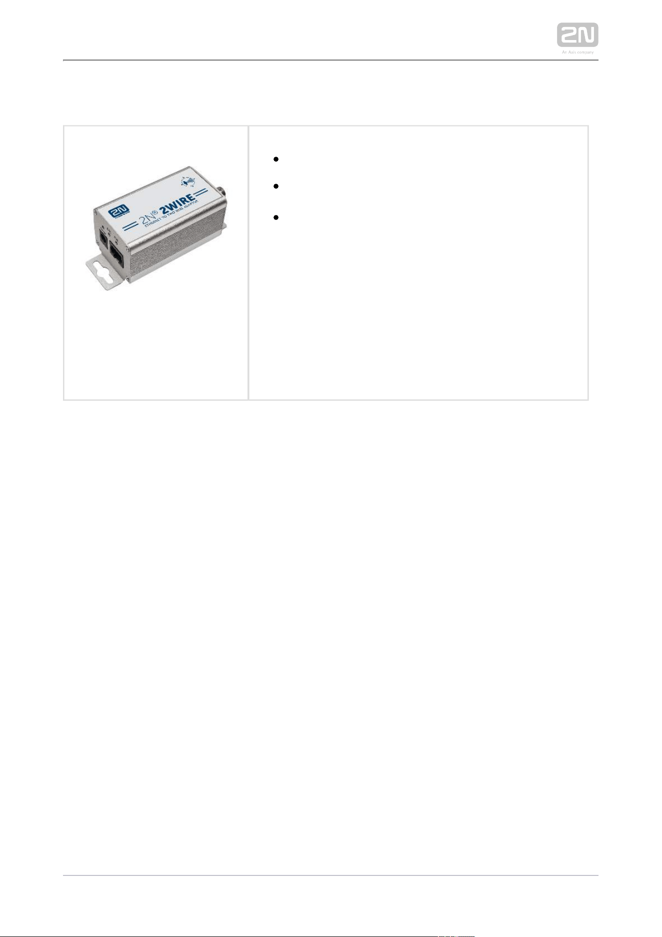
2N Part No. 9159014EU/US/UK
2N 2Wire
®
(set of 2 adaptors and power source for EU/US/UK)
The converter allows you to use the 2N 2Wire
®
existing wiring (2 wires) from your original door bell or
door intercom to connect any IP device. You don’t
have to configure anything, all you need is one 2N
®
unit at each end of the cable and a power supply 2Wire
connected to at least one of these units.
The unit then provides PoE power not only 2N 2Wire
®
to the second converter, but also to all the other
connected IP end devices.
2N TELEKOMUNIKACE a.s., www.2n.cz 42/319
RFID 13 MHz
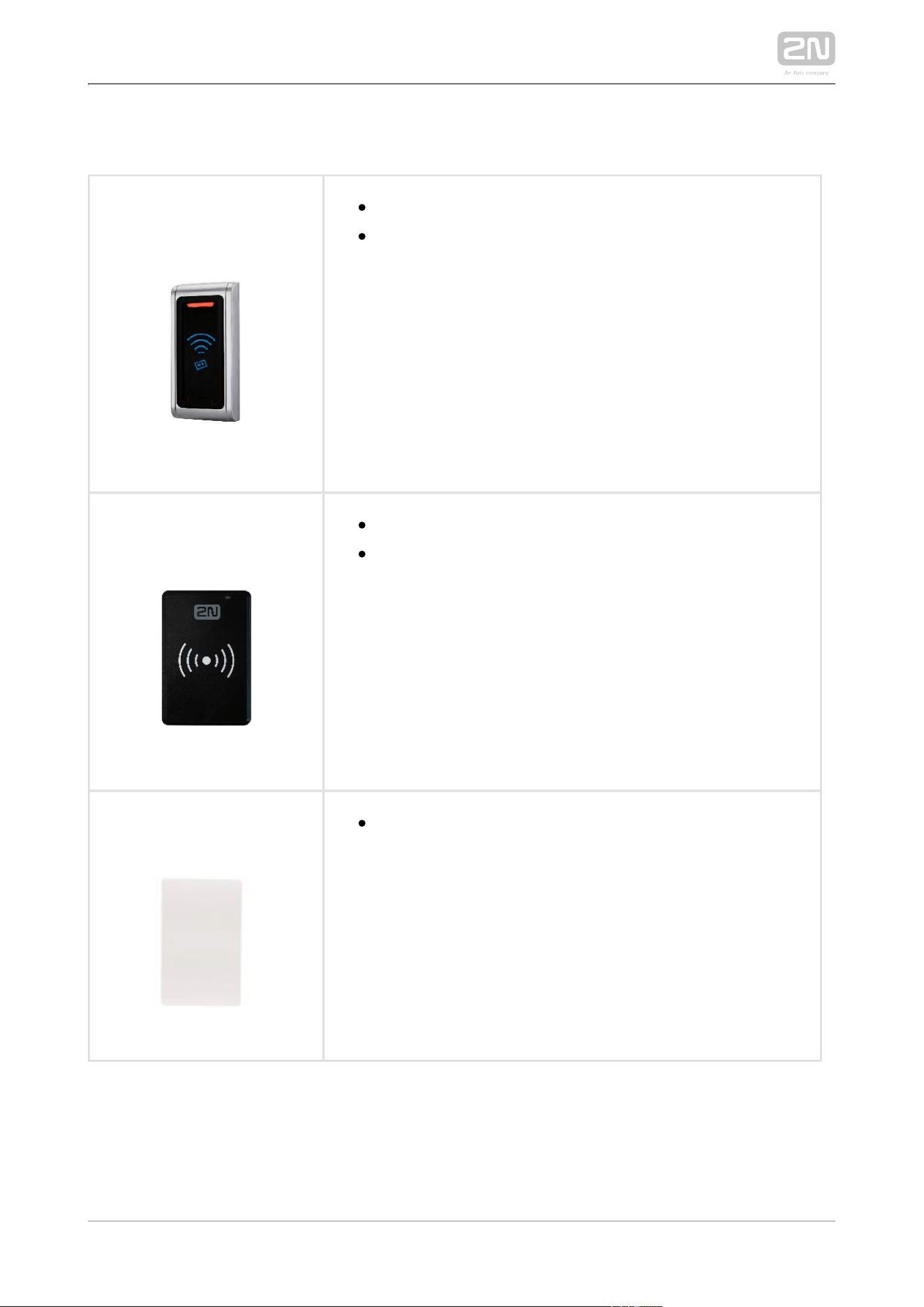
2N Part No. 9159031
Axis Part No. 01390-001
External 13.56 MHz Mifare RFID card reader, Wiegand
Secondary reader for connection to an internal reader.
Allows control of card entry from both sides of the
door. IP68 cover, also suitable for exteriors. Reads
cards:
ISO14443A (Mifare, DESFire)
PicoPass (HID iClass)
FeliCa
ST SR(IX)
2N Mobile Key
®
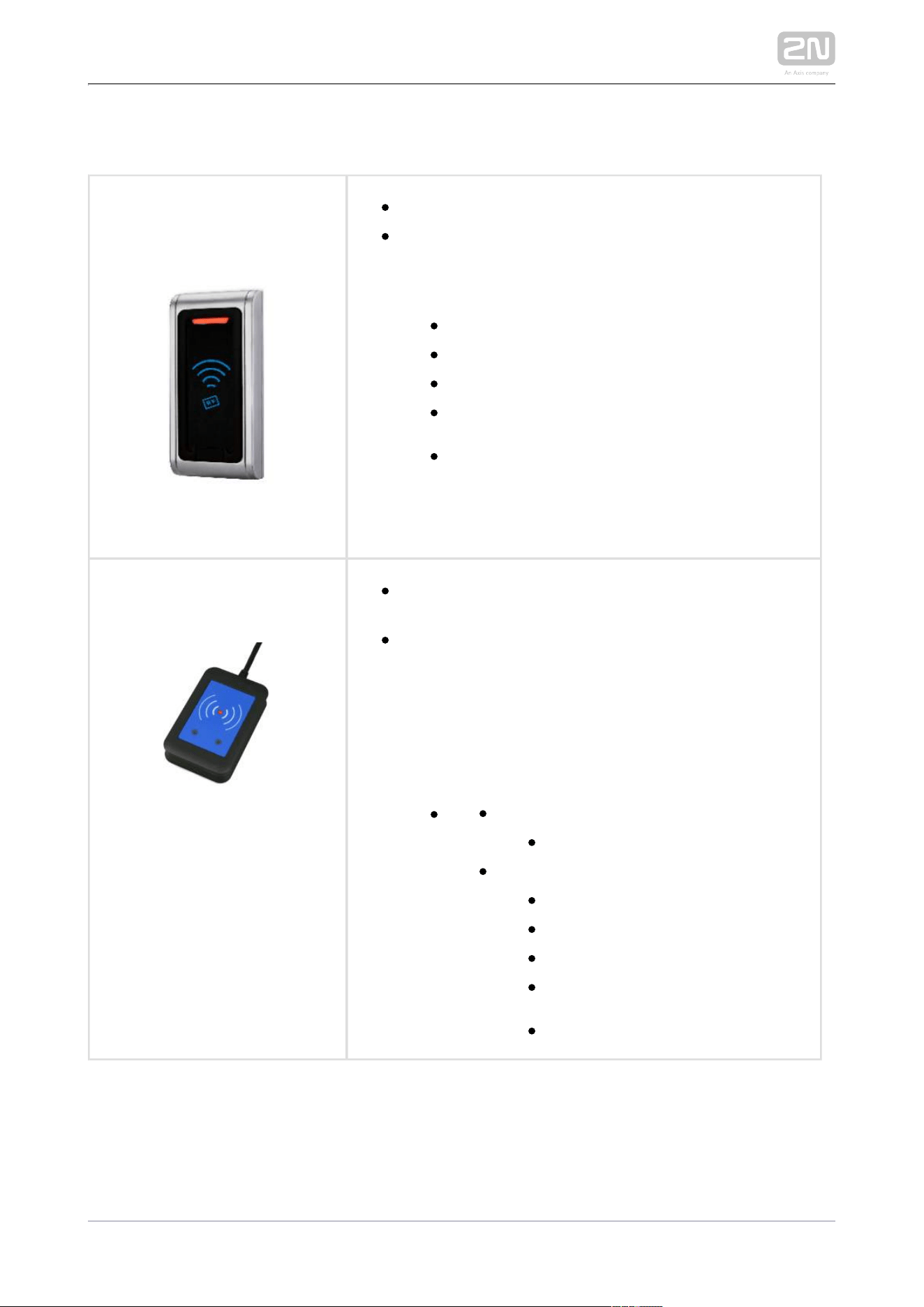
2N Part No. 9137421E
Axis Part No. 01400-001
Ext. RFID Reader 13.56 MHz, 125 kHz + NFC/HCE (USB
interface)
External RFID card reader for connection to PC using a
USB interface. Suitable for system administration and
adding 13.56 MHz, 125 kHz cards and Android platform
devices supporting NFC/HCE using 2N IP intercom
web interface or the 2N Access Commander
®
application. It reads the same types of cards and
devices as card readers in :2N IP intercoms
125 kHz
EM4xxx
13.56 MHz
ISO14443A (Mifare, DESFire)
PicoPass (HID iClass)
FeliCa
ST SR(IX)
2N Mobile Key
®
2N TELEKOMUNIKACE a.s., www.2n.cz 43/319
2N Part No. 9137424E
Ext. secured RFID Reader 13.56 MHz, 125 kHz + NFC
/HCE (USB interface)
External secured RFID card reader for connection to
PC using a USB interface. Suitable for system
administration and adding 13.56 MHz, 125 kHz cards
and Android platform devices supporting NFC/HCE
using web interface or the 2N IP intercom 2N Access
®
application. It reads the same types of Commander
cards and devices as card readers in :2N IPintercoms
125 kHz
EM4xxx
13.56 MHz
ISO14443A (Mifare, DESFire)
PicoPass (HID iClass)
FeliCa
ST SR(IX)
2N Mobile Key
®
HID SE (Seos, iClass SE, Mifare SE)
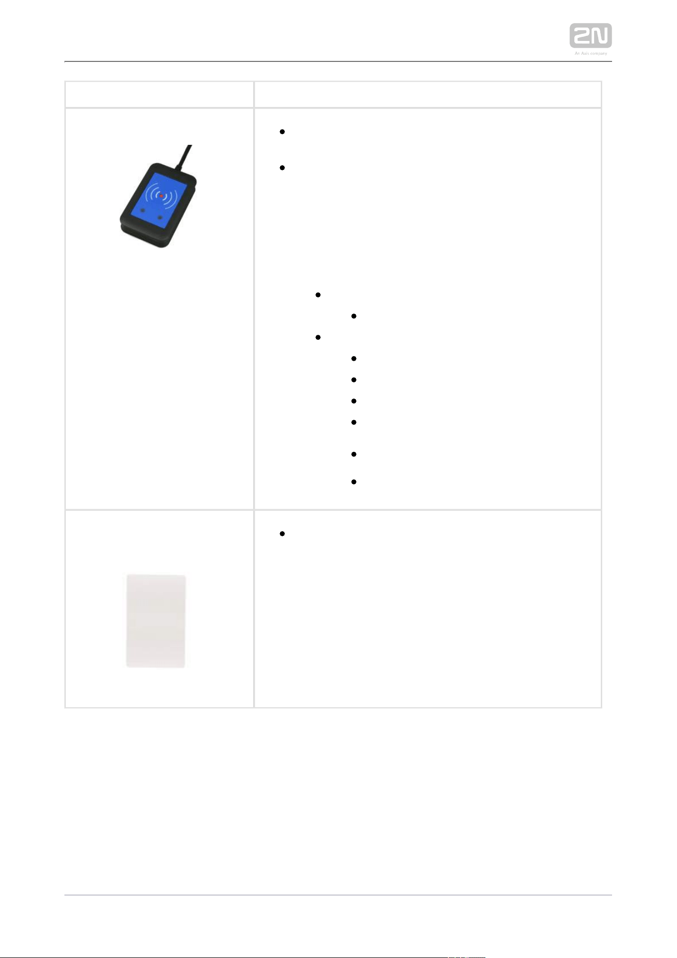
91341732N Part No.
Axis Part No. 01384-001
Mifare Classic 1k RFID card, 13.56 MHz

2N TELEKOMUNIKACE a.s., www.2n.cz 44/319
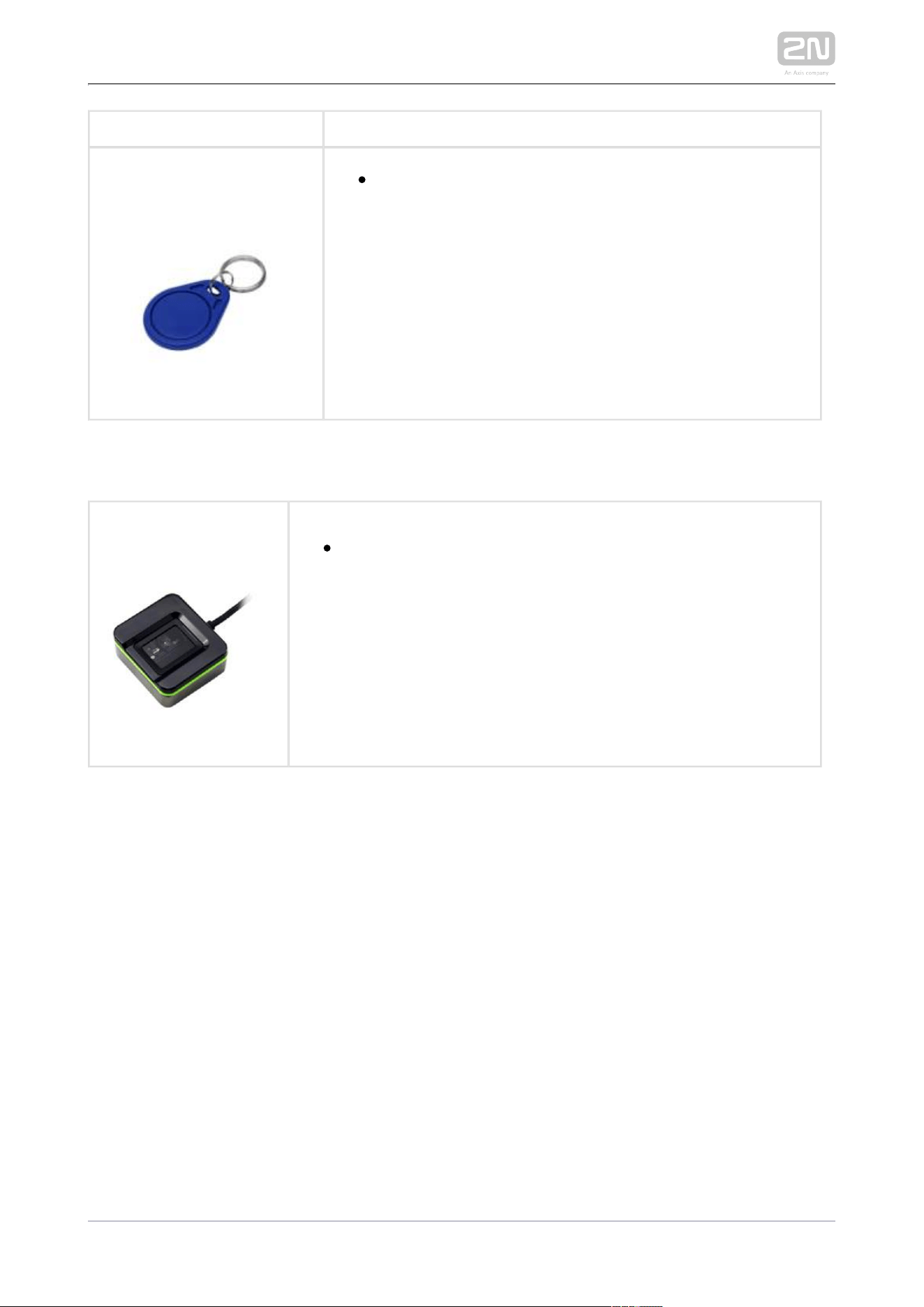
2N Part No. 9134174
Axis Part No. 01385-001
Mifare Classic 1k RFID fob, 13.56 MHz
2N TELEKOMUNIKACE a.s., www.2n.cz 45/319
RFID 125 kHz
2N Part No. 9159030
Axis Part No. 01389-001
External 125 kHz RFID card reader
Secondary reader for connection to an internal reader.
Allows control of card entry from both sides of the door.
IP67 cover, also suitable for exteriors. Reads EM4xxx
cards.
9137420E2N Part No.
Axis Part No. 01399-001
USB RFID card reader 125 kHz
External RFID card reader for connection to a PC using a
USB interface. Suitable for system management and the
addition of EM4xxx cards via the PC application, 2N
®
.Access Commander
9134165E2N Part No.
Axis Part No. 01395-001
RFID card, type EM4100, 125 kHz
2N TELEKOMUNIKACE a.s., www.2n.cz 46/319
9134166E2N Part No.
Axis Part No. 01396-001
RFID fob, type EM4100, 125 kHz
Biometry
2N Part No. 9137423E
Axis Part No. 01401-001
2N IP intercom
®
- external fingerprint reader (USB interface)
2N TELEKOMUNIKACE a.s., www.2n.cz 47/319
External switches
91590102N Part No.
Axis Part No. 01386-001
2N
®
Security Relay
A handy add-on that significantly enhances door
entry security as it prevents tampering with the
intercom and forced opening of the lock. To be
installed between intercom and lock, powered by
the intercom.
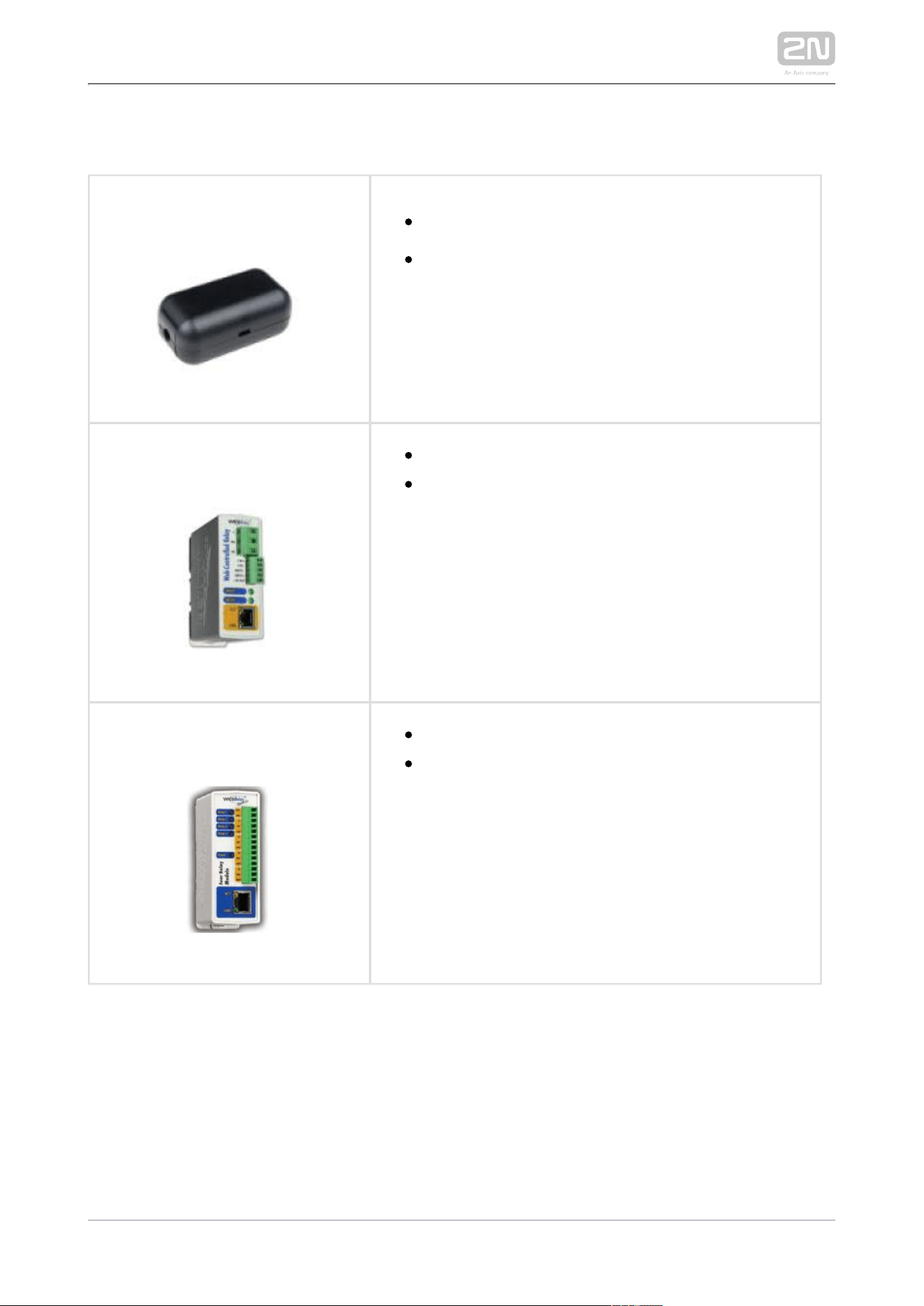
9137410E2N Part No.
Axis Part No. 01397-001
External IP Relay – 1 output
Standalone IP device which can be controlled by
HTTP commands sent by intercom, which can 2N IP
thus control devices on unlimited distance.
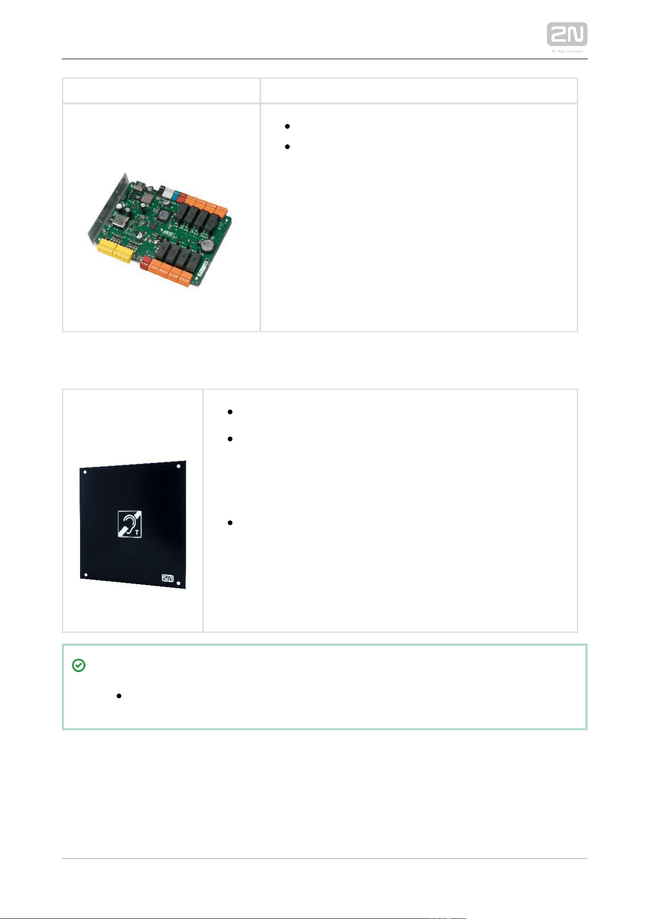
9137411E 2N Part No.
Axis Part No. 01398-001
External IP Relay – 4 outputs, PoE
Standalone IP device which can be controlled by
HTTP commands sent by intercom, which can 2N IP
thus control devices on unlimited distance.
2N TELEKOMUNIKACE a.s., www.2n.cz 48/319
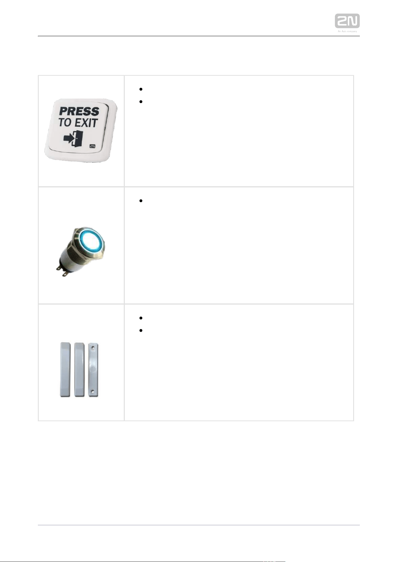
91605012N Part No.
Axis Part No. 0820-001
AXIS A9188 Network I/O relay module
Lift control relay module for up to 8 floors
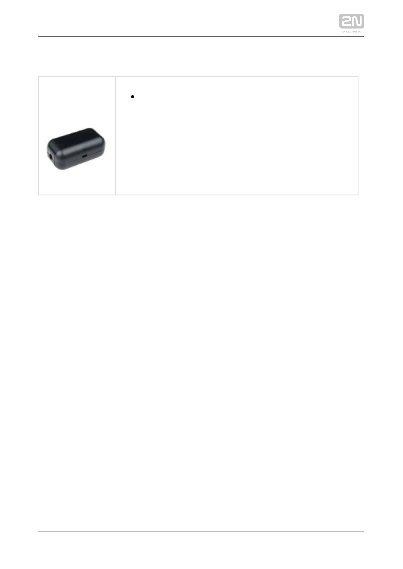
Induction loop
2N Part No. 9155043
Axis Part No. 01265-001
Induction loop module – antenna
External antenna boosts the range of usability of the induction
loop, so that the hearing impared user of hearing aid with
telecoil can receive the audio signal in wider area. It has to be
used with . A 40 cm long interconnecting Part No. 9155041
cable is included.
Dimensions: 233 (W) x 233 (H) mm
Tip
FAQ: Induction loop – How to connect it with 2N IP intercom
2N TELEKOMUNIKACE a.s., www.2n.cz 49/319
Sensors and Switches
2N Part No. 9159013
Exit button
A button for logic input connection for opening a door inside a
building.
2N Part No. 9154004
Axis Part No. 01479-001
Water-proof metal button
2N Part No. 9159012
Axis Part No. 01388-001
Magnetic door contact
Door installation set that enables the status of door opening to
be ascertained. Used when the intercom is used for door
protection to detect when the door is open or opened by
violence.
2N TELEKOMUNIKACE a.s., www.2n.cz 50/319
Additional Modules
2N Part No. 9159011
Axis Part No. 01387-
001
The 2N
®
Wiegand Isolator is designed for galvanic isolation of
two devices separately power supplied and interconnected via the
Wiegand bus. The 2N
®
protects the Wiegand Isolator
interconnected devices against communication errors and/or
damage.
2N TELEKOMUNIKACE a.s., www.2n.cz 51/319
License
2N Part No.
9137905
Axis Part No.
01376-001
Enhanced Audio
2N Part No.
9137906
Axis Part No.
01377-001
Enhanced Video
2N Part No.
9137907
Axis Part No.
01378-001
Enhanced Integration
2N Part No.
9137908
Axis Part No.
01379-001
Enhanced Security
2N Part No.
9137909
Axis Part No.
01380-001
Gold
2N Part No.
9137910
Axis Part No.
01381-001
InformaCast
2N Part No.
9137915
Axis Part No.
01382-001
NFC
2N TELEKOMUNIKACE a.s., www.2n.cz 53/319
1.2 Terms and Symbols
The following symbols and pictograms are used in the manual:
Safety
Always abide by this information to prevent persons from injury.
Warning
Always abide by this information to prevent damage to the device.
Caution
Important information for system functionality.
Tip
Useful information for quick and efficient functionality.
Note
Routines or advice for efficient use of the device.


2N TELEKOMUNIKACE a.s., www.2n.cz 55/319
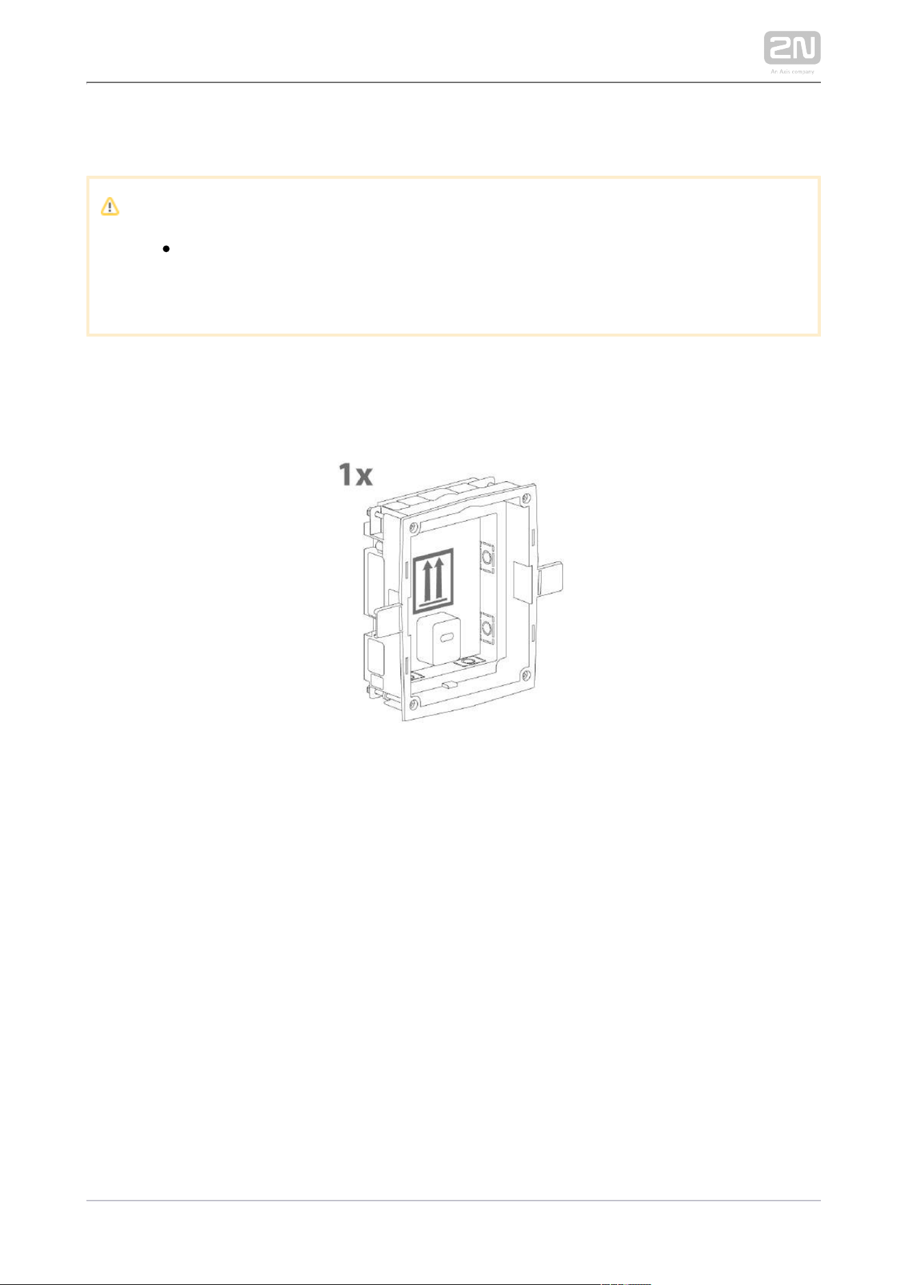
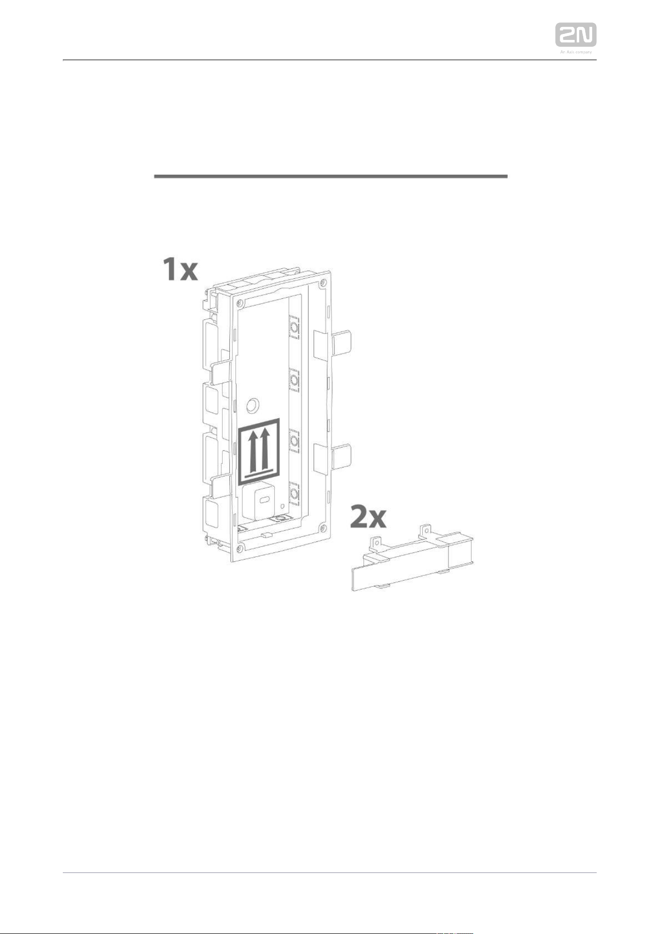
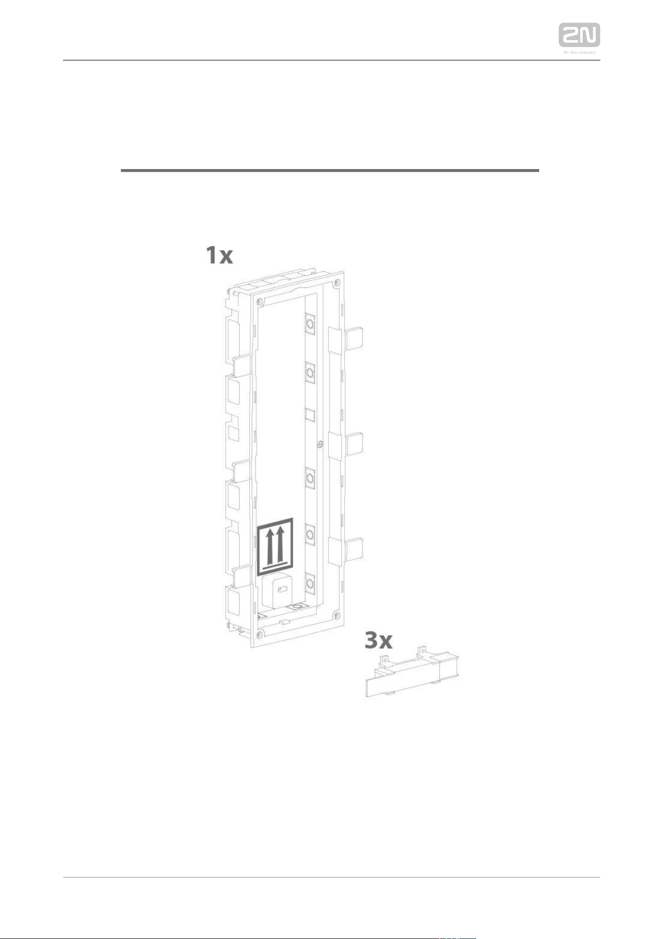
2.1 Before You Start
Product Completeness Check
Before you start please check whether the contents of the package of your new
complies with the following list.2N IP Verso
®
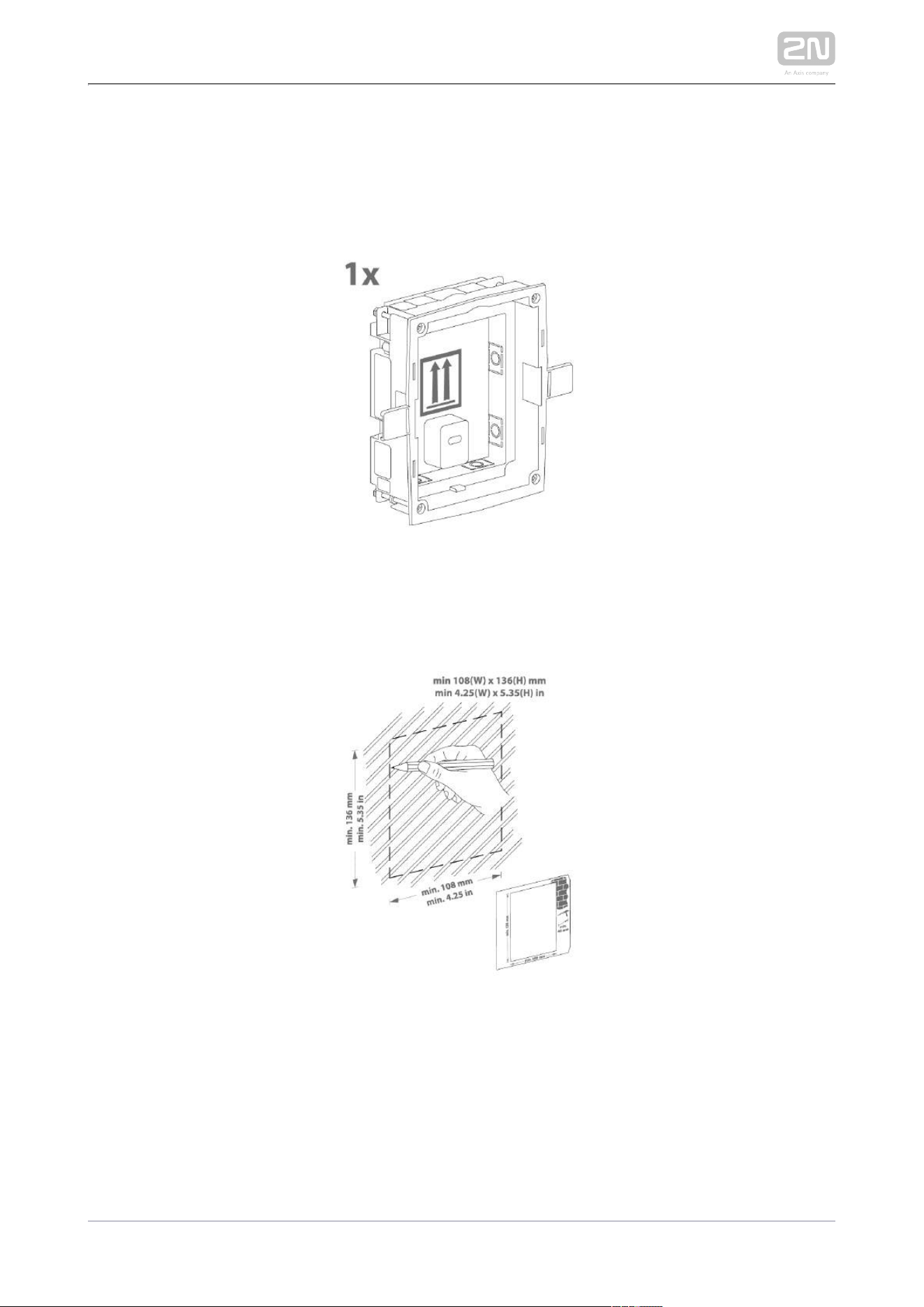
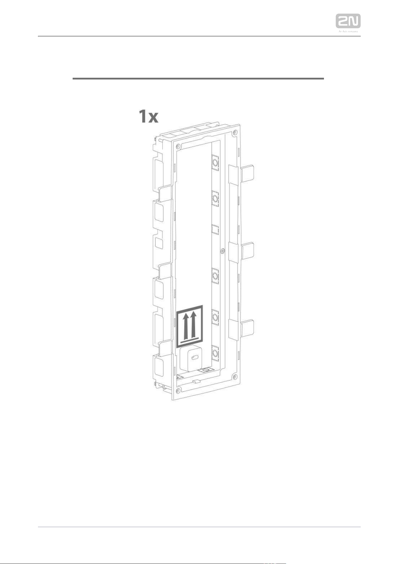
1x 2N IP Verso
®

2N TELEKOMUNIKACE a.s., www.2n.cz 56/319
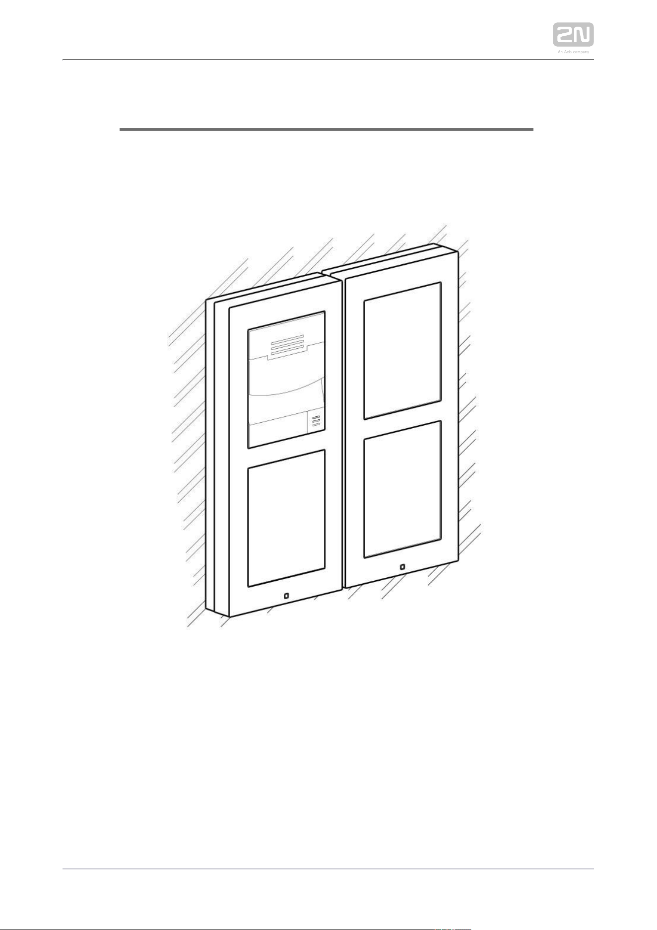
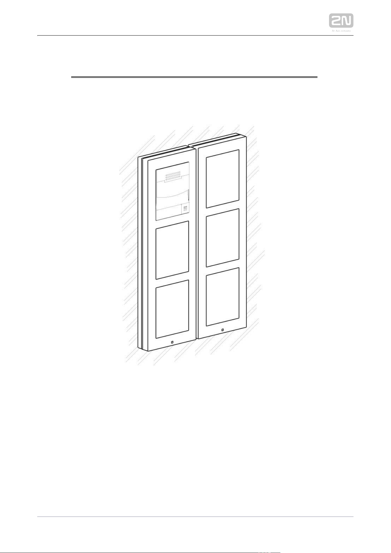
2.2 Mechanical Installation
Mounting Types Overview
Refer to the table below for a list of mounting types and necessary components. You
can assemble multiple units in all mounting types.
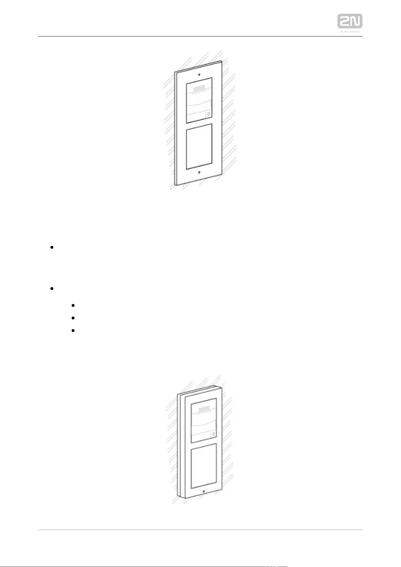
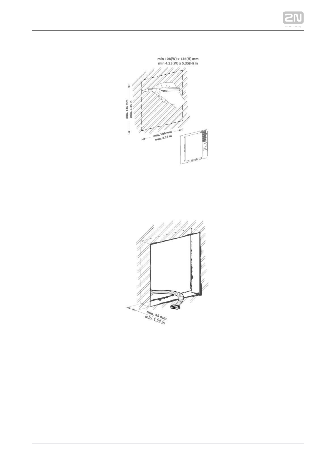
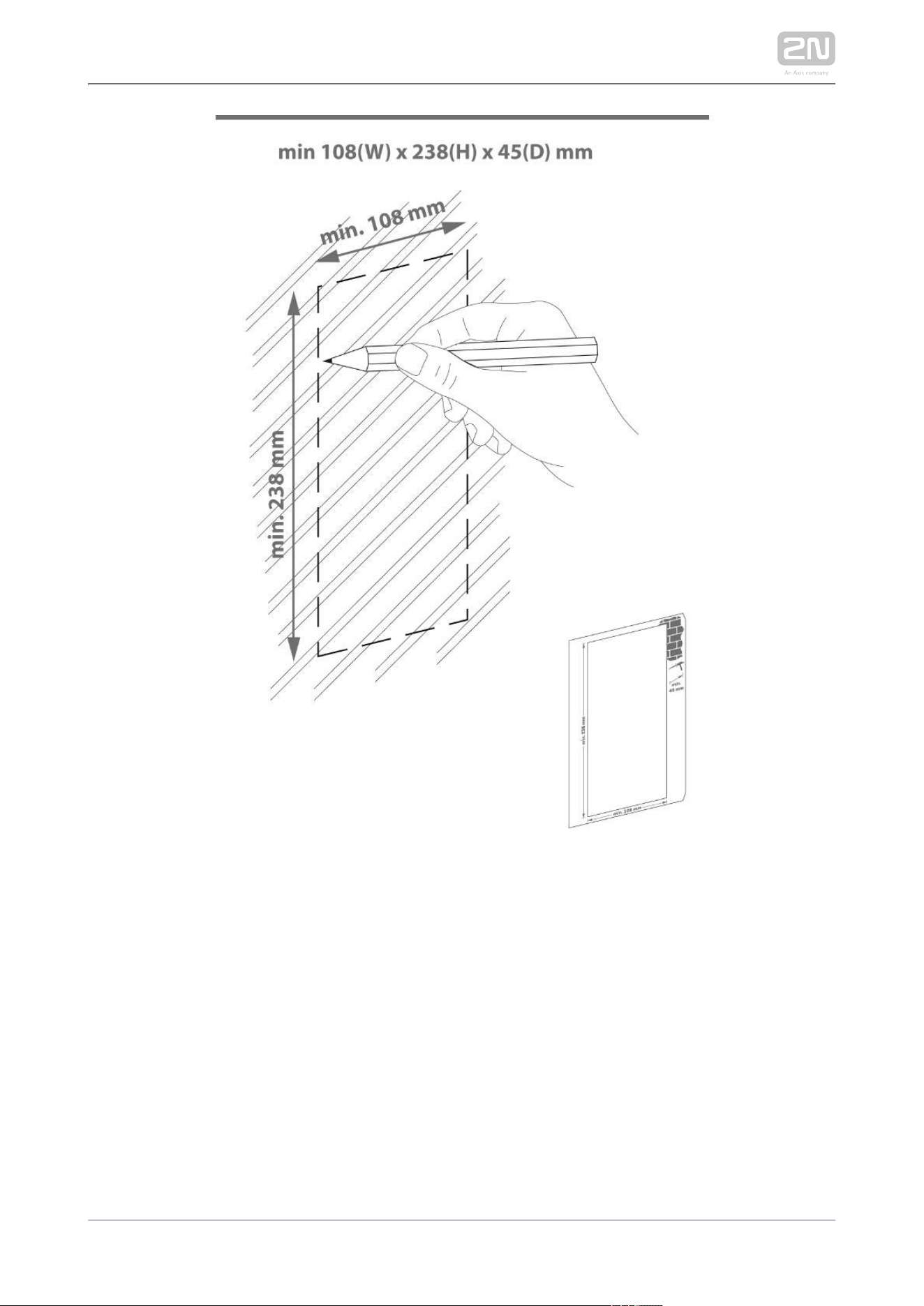
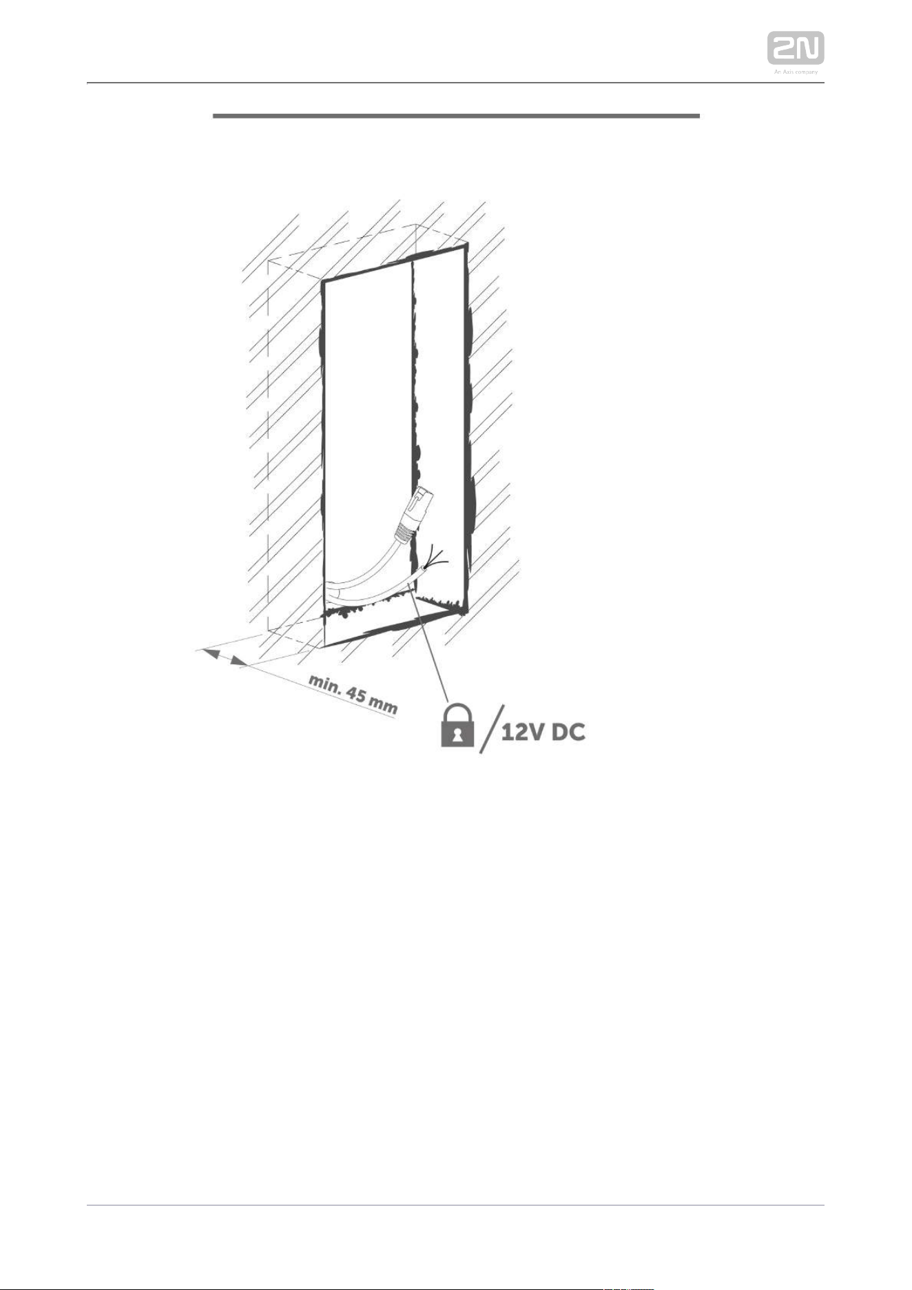
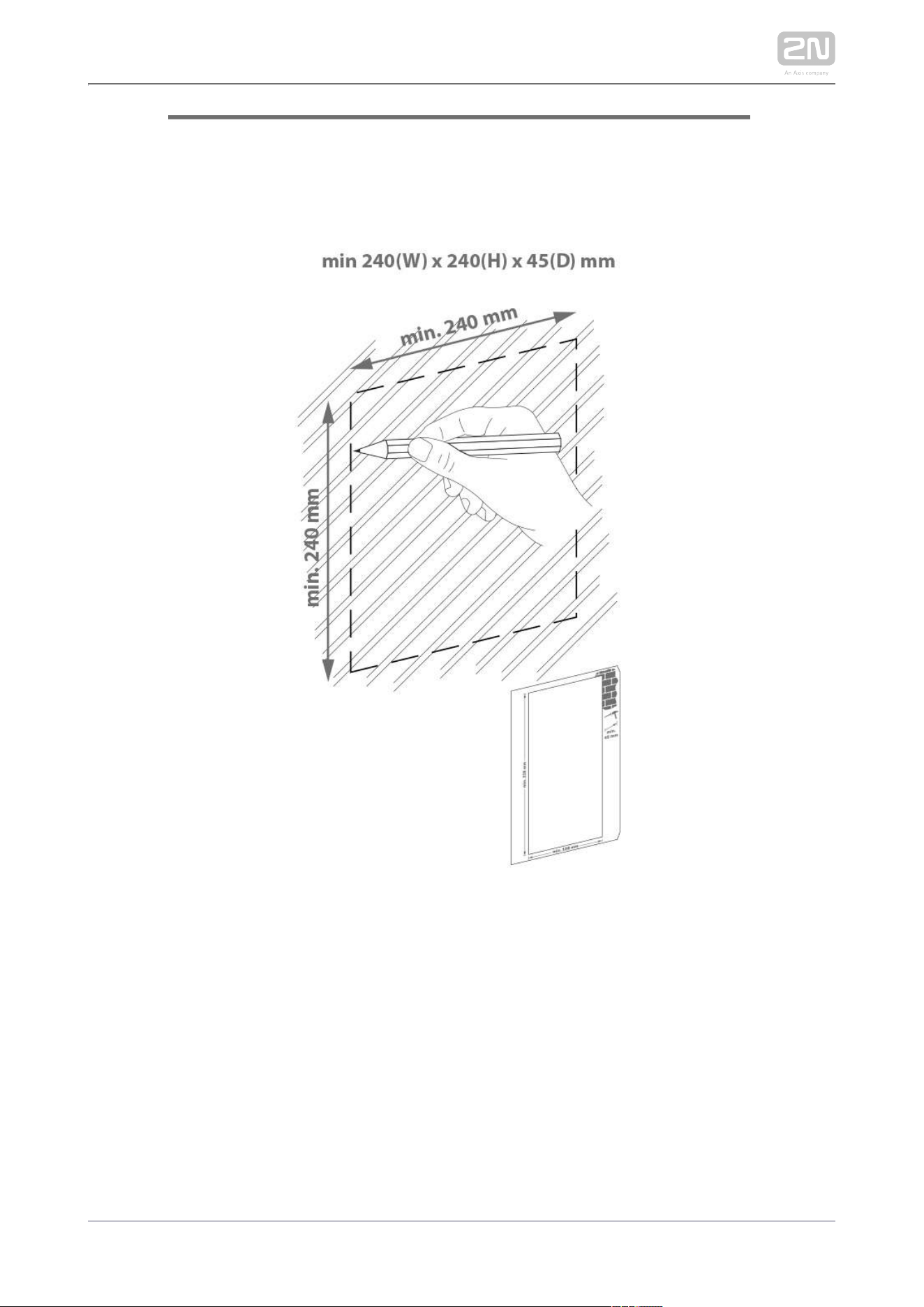
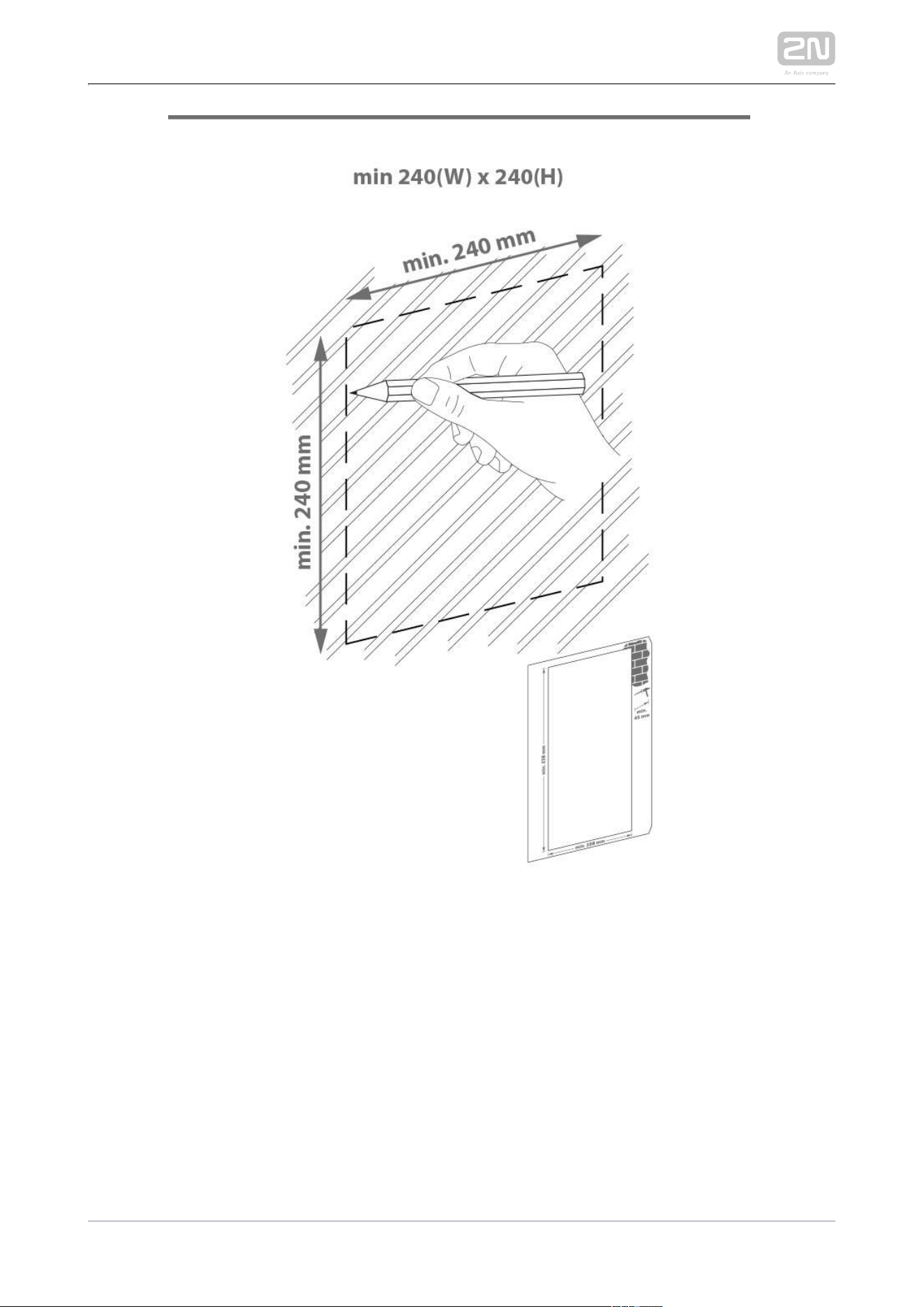
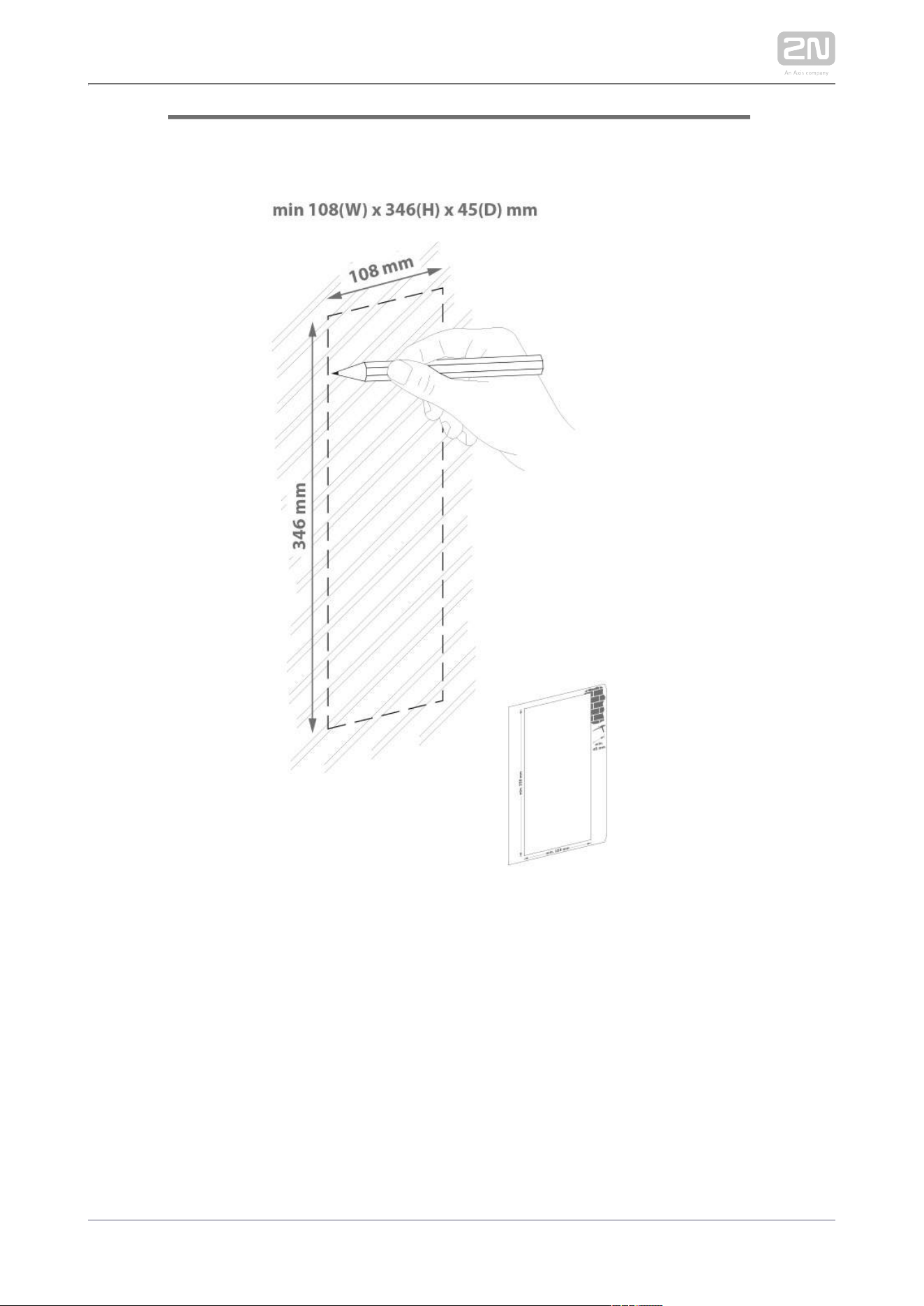
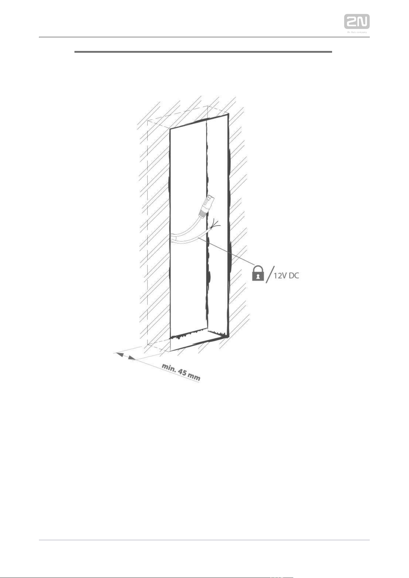
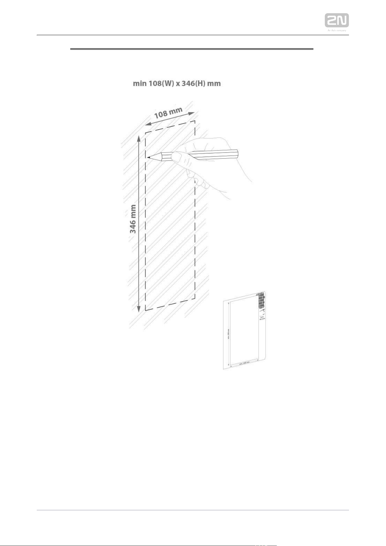
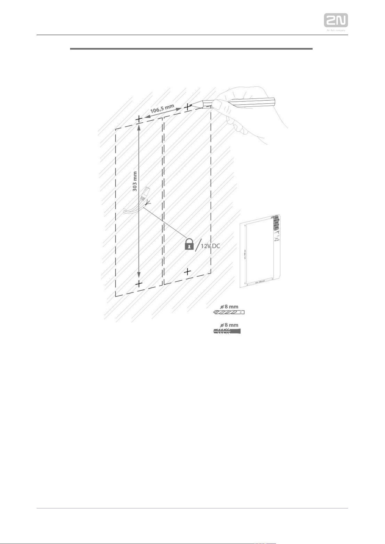
Flush mounting – classic bricks
incl. hollow bricks, thermally insulated walls, etc.
What you need for mounting:
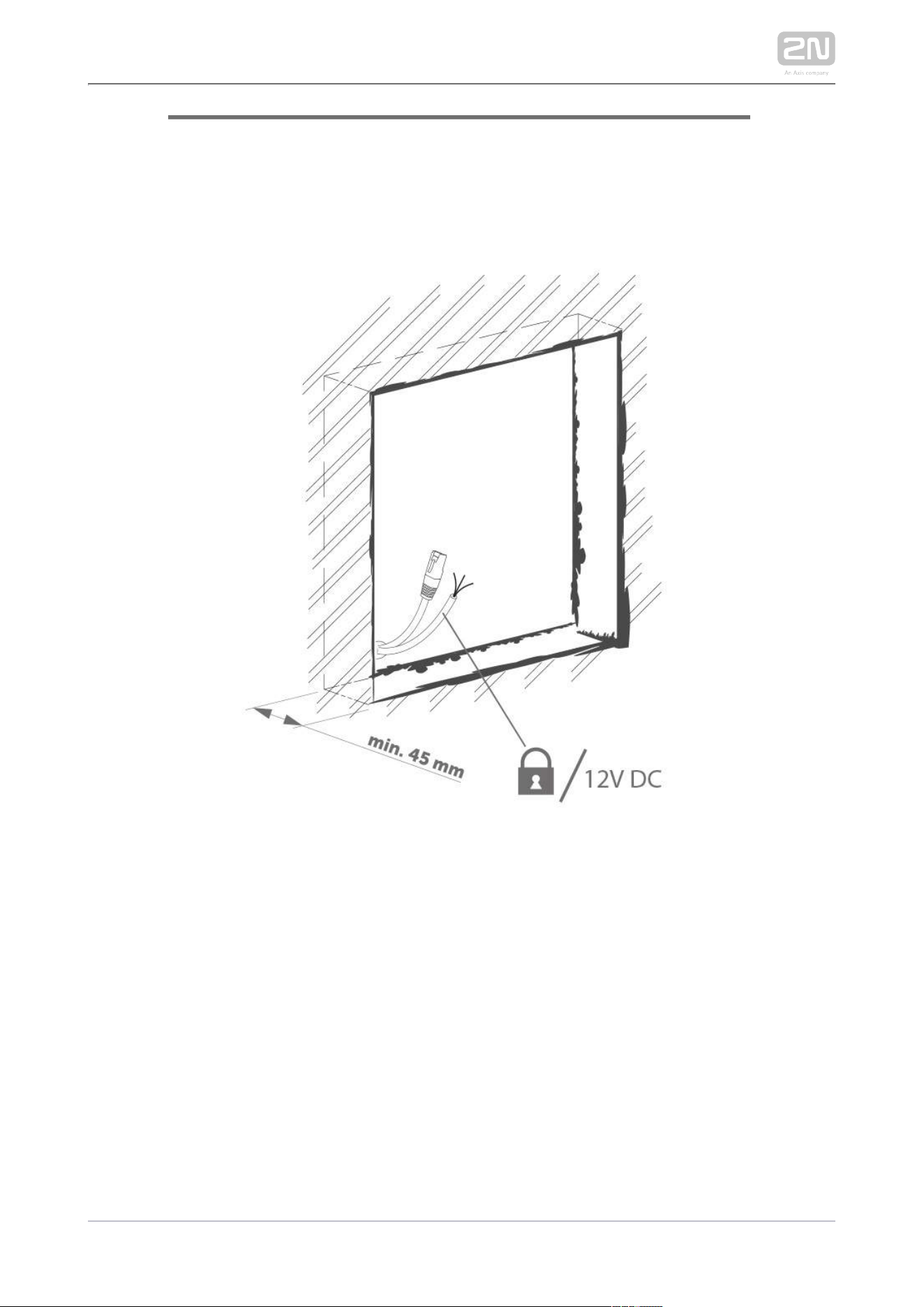
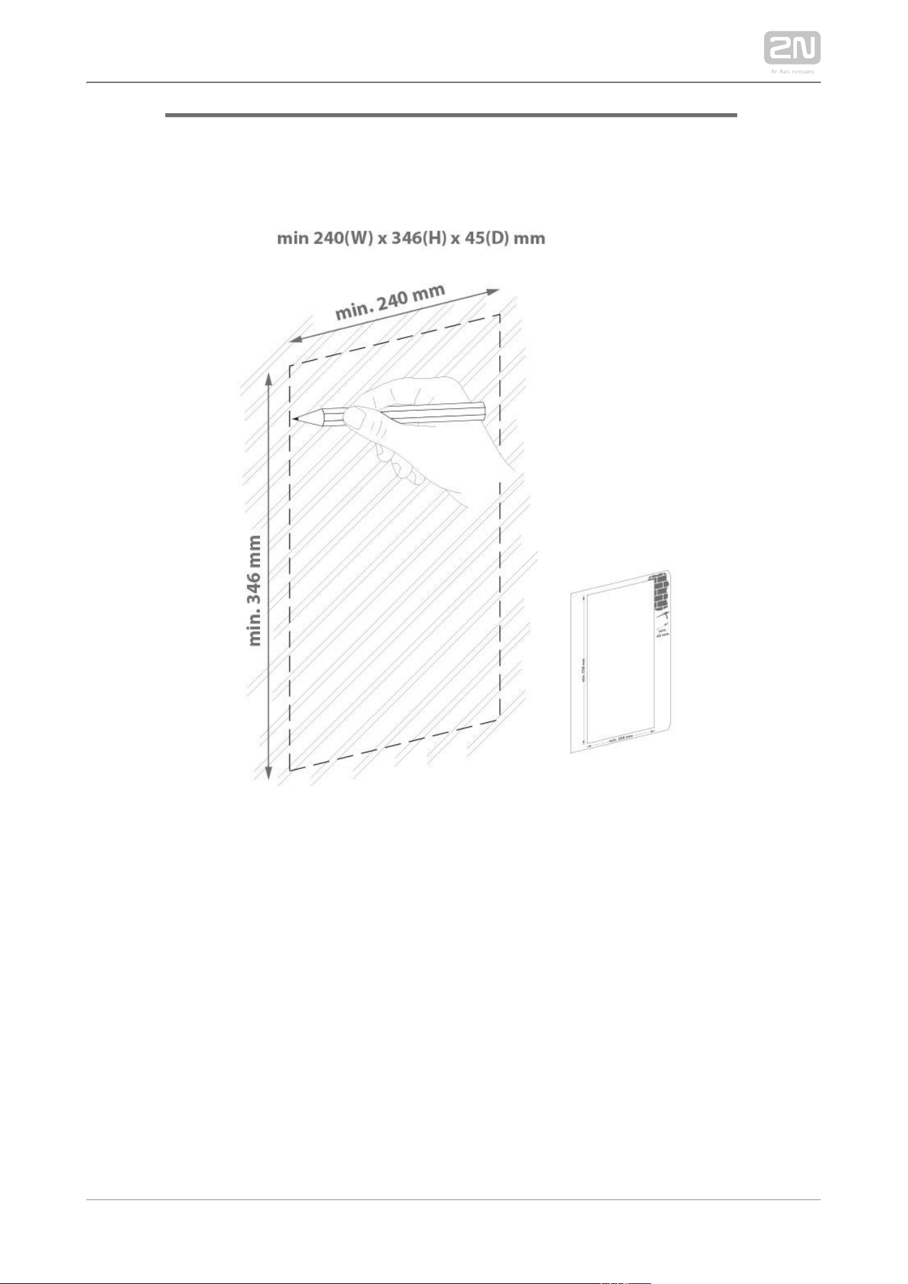
a properly cut hole as instructed in the box package
Plaster, mounting glue, mounting foam or mortar as necessary
2N IP Verso
®
, flush mounting boxes and frames
1 module: box Part No. , frame Part No.9155014 9155011
2 modules: box Part No. , frame Part No. 9155015 9155012
3 modules: box Part No. , frame Part No. 9155016 9155013
Flush mounting – plasterboard
What you need for mounting:
a properly cut hole as instructed in the box package
2N IP Verso
®
, flush mounting boxes and frames
1 module: box Part No. , frame Part No. 9155014 9155011
2 modules: box Part No. , frame Part No. 9155015 9155012
3 modules: box Part No. , frame Part No. 9155016 9155013
2N TELEKOMUNIKACE a.s., www.2n.cz 57/319
Surface mounting
concrete and steel structures, entry barrier columns, interior, etc.
What you need for mounting:
2N IP Verso
®
plus the respective frames
1 module: frame Part No. 9155021
2 modules: frame Part No. 9155022
3 modules: frame Part No. 9155023
For not flat surface use according to the module number backplate Part No –9155061
.9155067
2N TELEKOMUNIKACE a.s., www.2n.cz 58/319
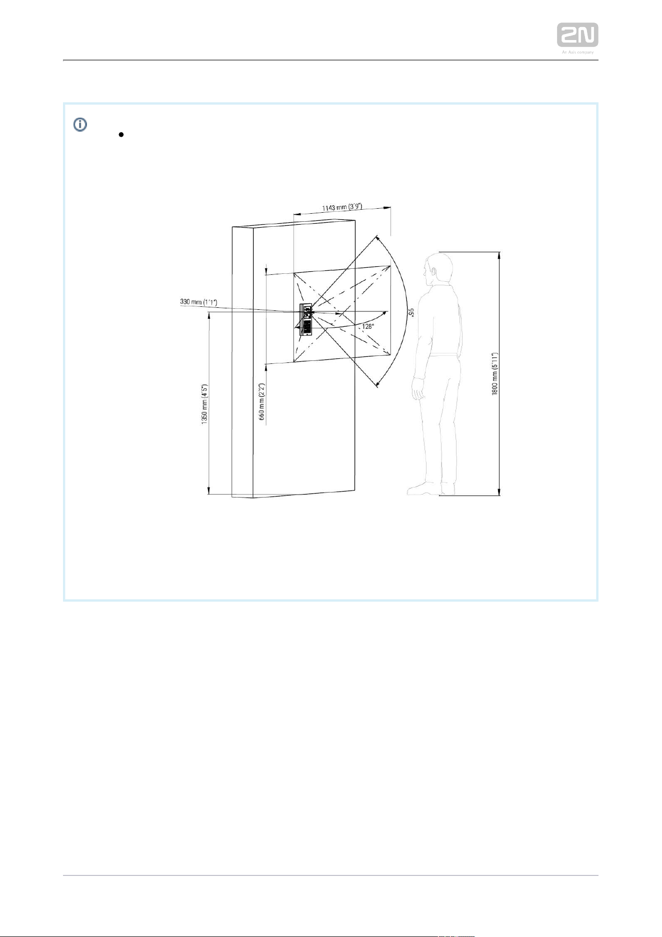
The recommended standard installation height is 1350 mm from the
ground to the device camera level. The installation height may vary
depending on the device use.
2N TELEKOMUNIKACE a.s., www.2n.cz 59/319
Caution
The warranty does not apply to the product defects and failures arisen
as a result of improper mounting (in contradiction herewith). The
manufacturer is neither liable for damage caused by theft within an area
that is accessible after the attached electric lock is switched. The
product is not designed as a burglar protection device except when
used in combination with a standard lock, which has the security
function.
When the proper mounting instructions are not met, water might get in
and destroy the electronics. It is because the communicator circuits are
under continuous voltage and water infiltration causes an electro-
chemical reaction. The manufacturer’s warranty shall be void for
products damaged in this way!
Do not remove the plastic film on the seal inside the frame, otherwise
water may leak and damage the electronic components.
General Mounting Principles
Tip
Select flush mounting where possible to make your product elegant
looking, more vandal resistant and more secure.
You are advised to buy the flush mounting boxes in advance and
commission your building company to do the masonry for you. This
approach helps you put your intercom exactly in the vertical position.
2N TELEKOMUNIKACE a.s., www.2n.cz 60/319
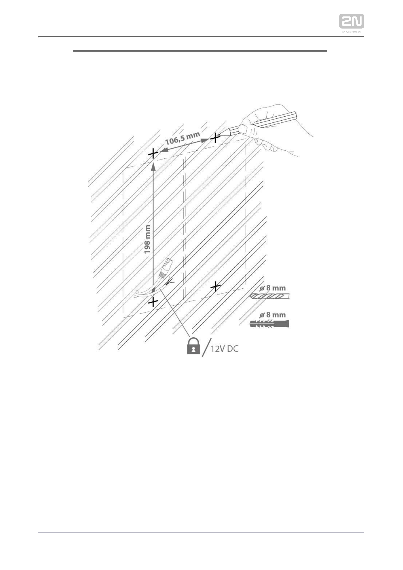
Caution
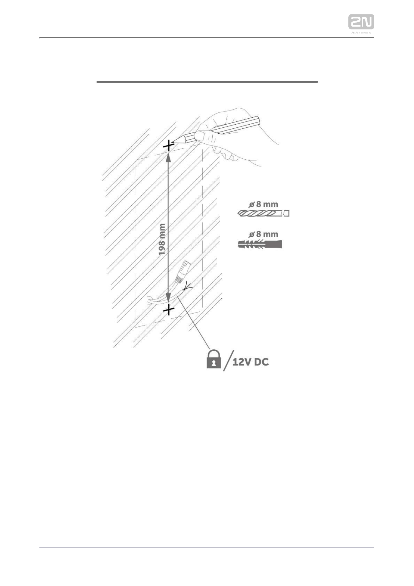
Make sure that the diameter of the dowel holes is accurate to avoid
falling out of the dowels! Use the mounting glue to secure the dowels if
necessary.
Make sure that the depth of the dowel holes is accurate!
Do not use low-quality dowels to avoid their pulling out of the wall!
Having removed the front panel, make sure that no dirt gets inside the
product (especially onto the sealing surface).
Never turn to align the box assembly after mounting. Make 2N IP Verso
®
sure that the flush mounting boxes have been installed accurately.
Check the plasterboard wall and room interior pressure values. If the
difference between the values is too great (as a result, e.g., of
overpressure ventilation), separate the intercom using, for example, the
mounting box enclosed and seal the cable passage to avoid speaker
damage.
Surface mounting may cause problems on places exposed to potential
vandalism (such as public garages, etc.). In this case, use steel anchoring
elements instead of the dowels and screws included in the delivery.
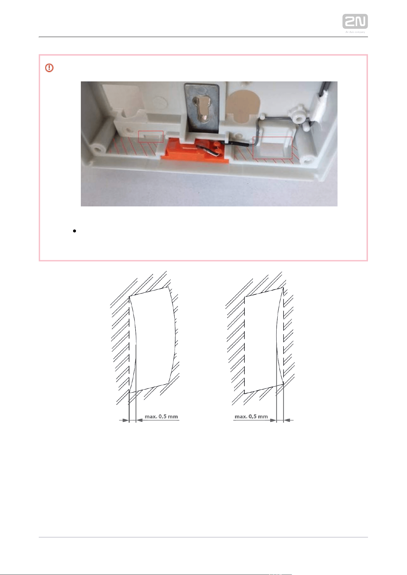
Make sure that the installation surface is perfectly flat with the maximum
inequality of 0.5 mm. (e.g. boards, glass, cut stone, etc). If this is not the
case, use a mounting backplate – or level the Part No 9155061 9155067,
wall surface.
Always use an installation backplate for uneven installation surfaces.
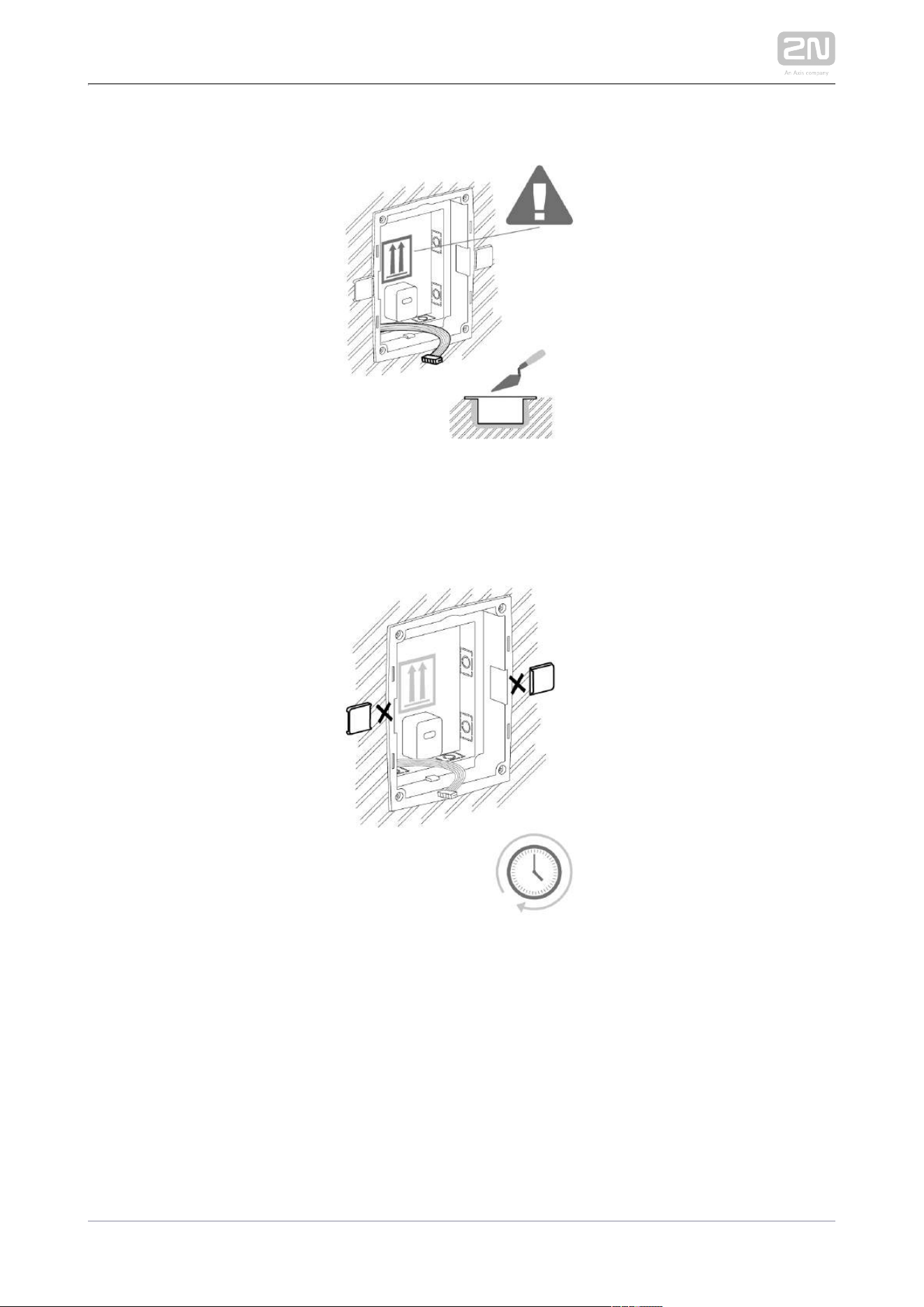
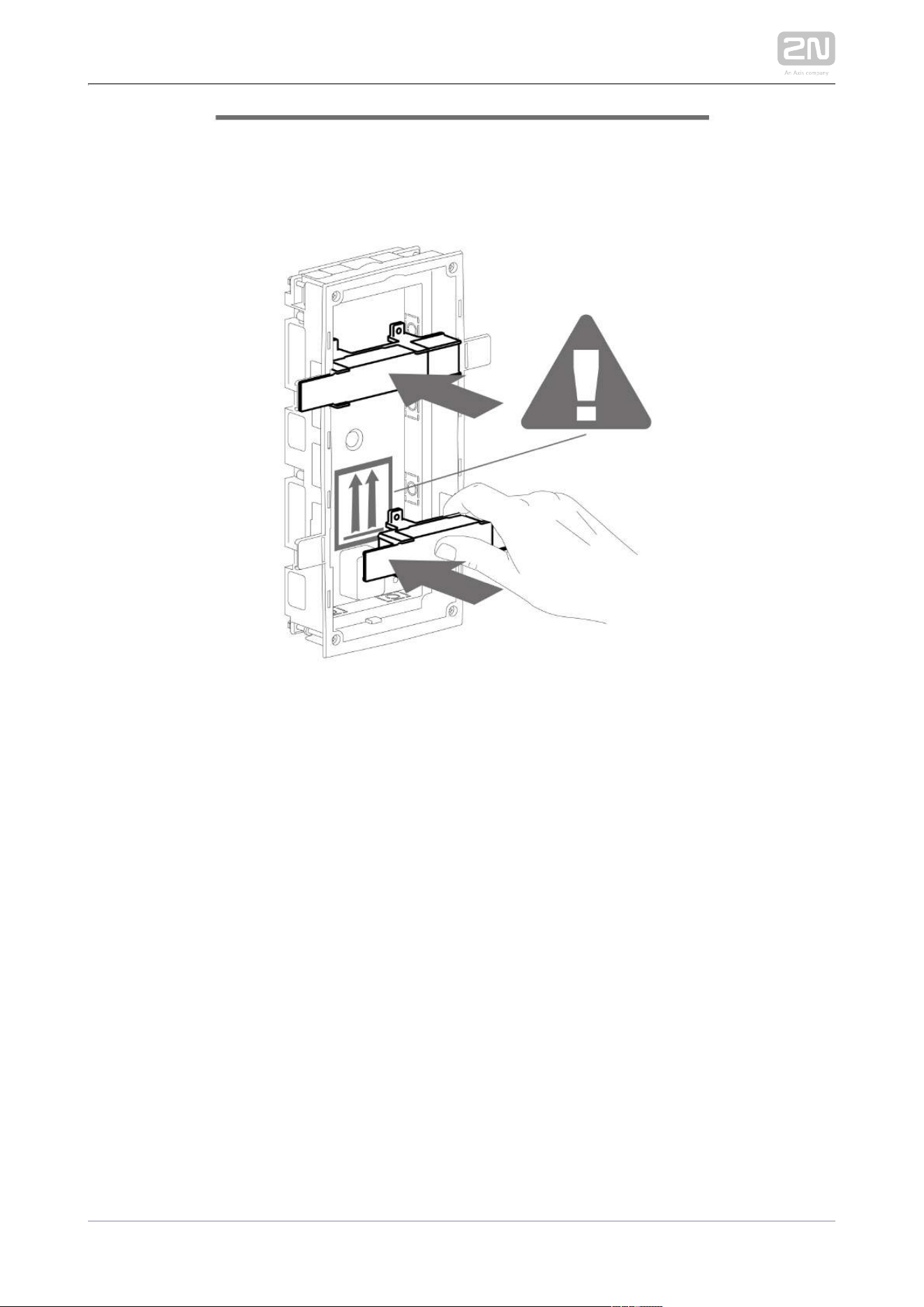
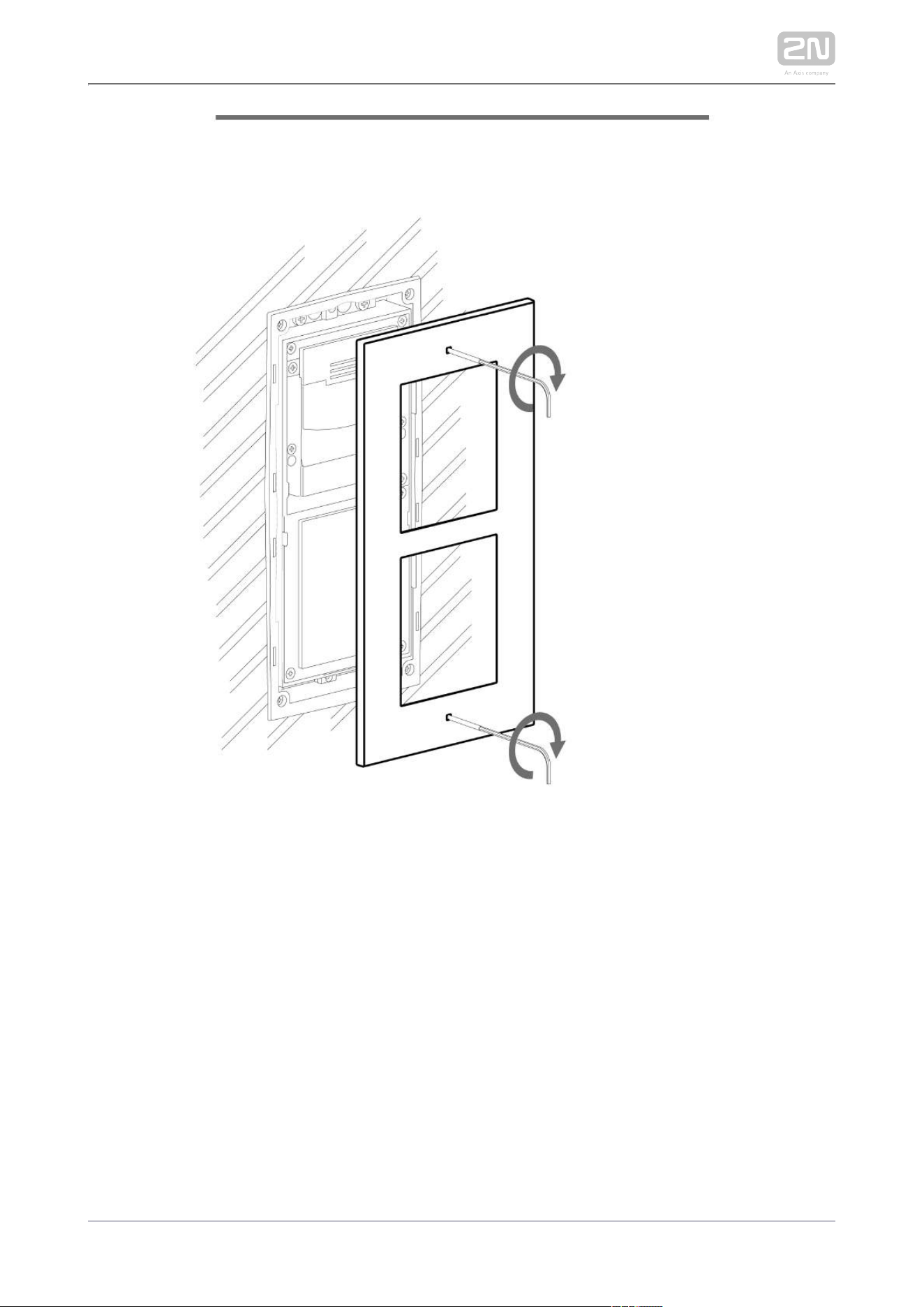
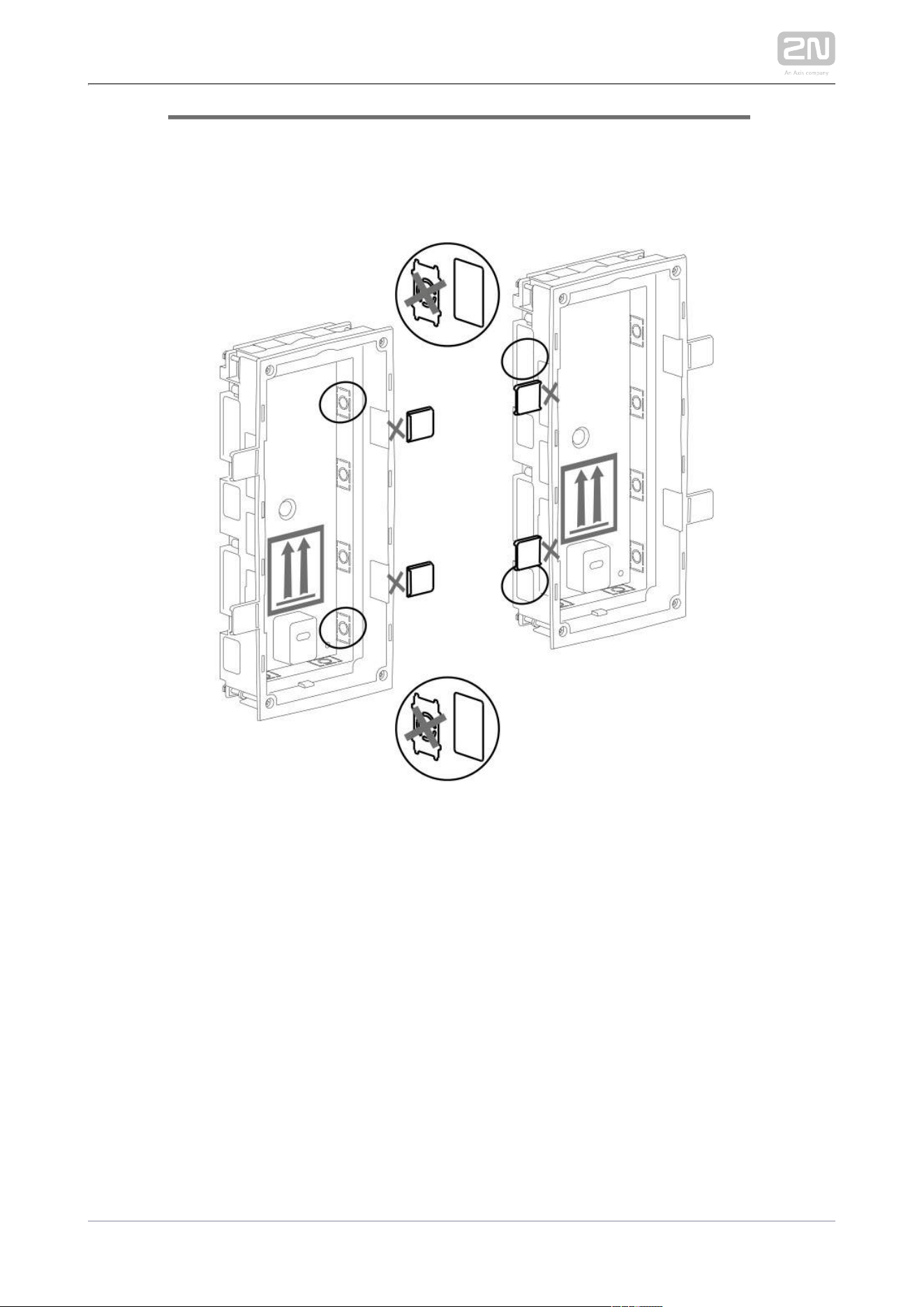
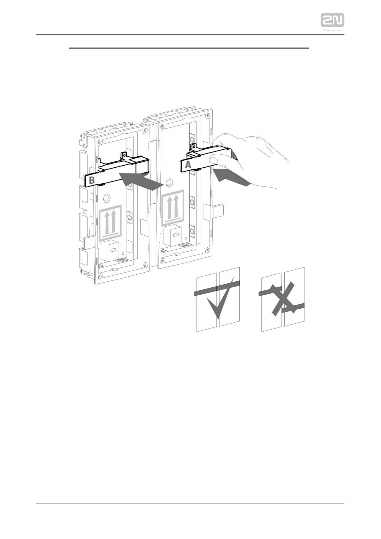
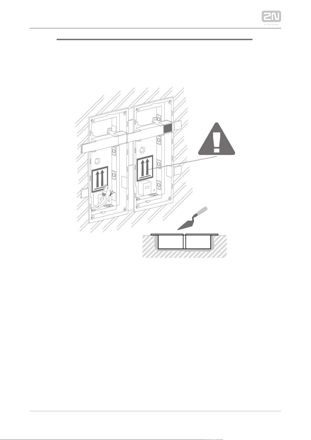
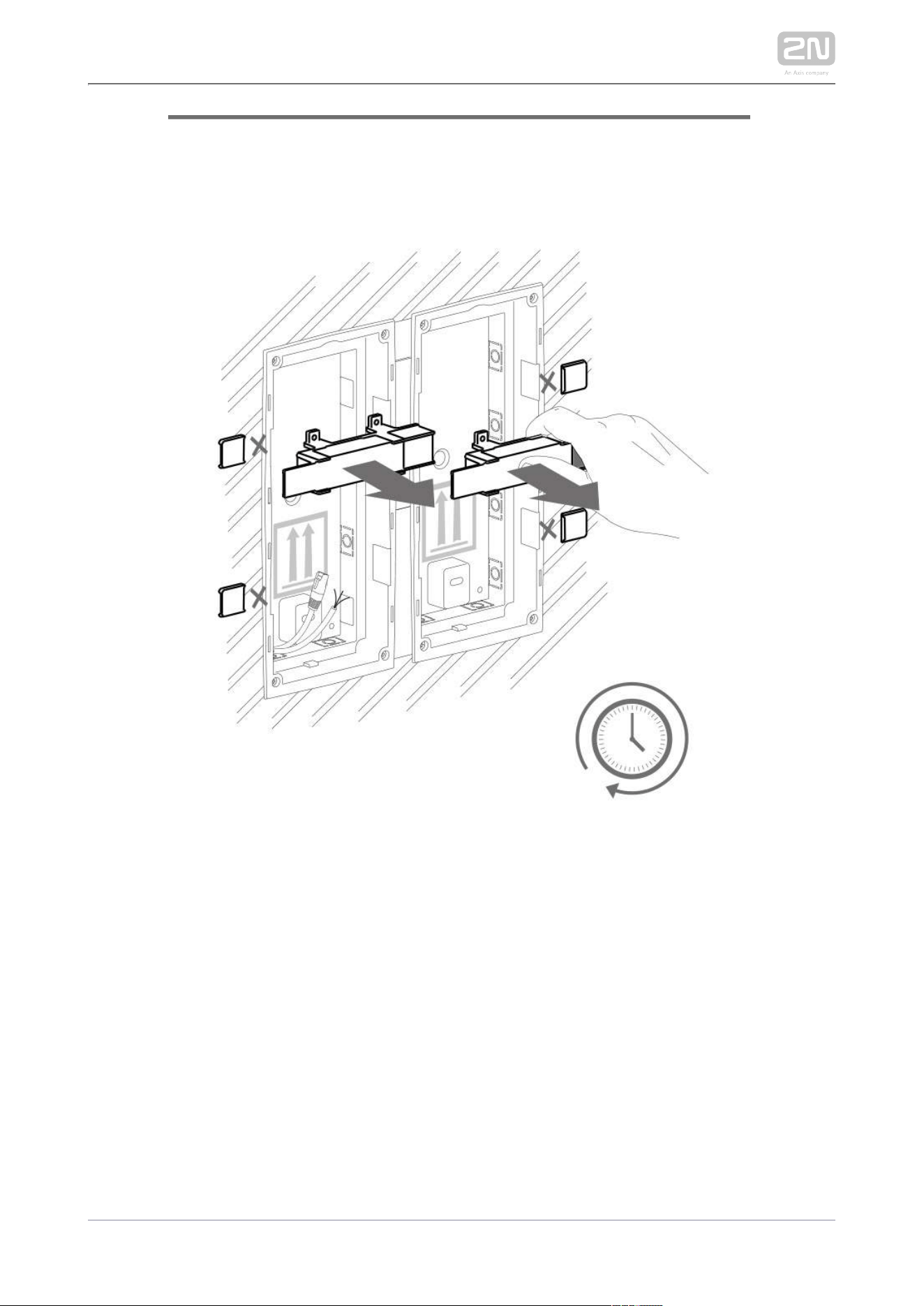
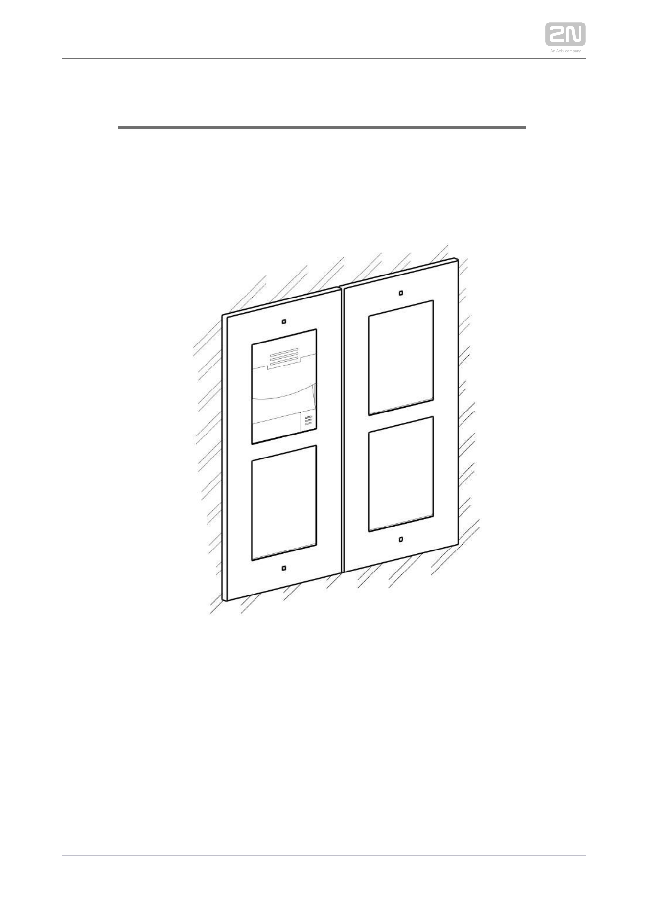
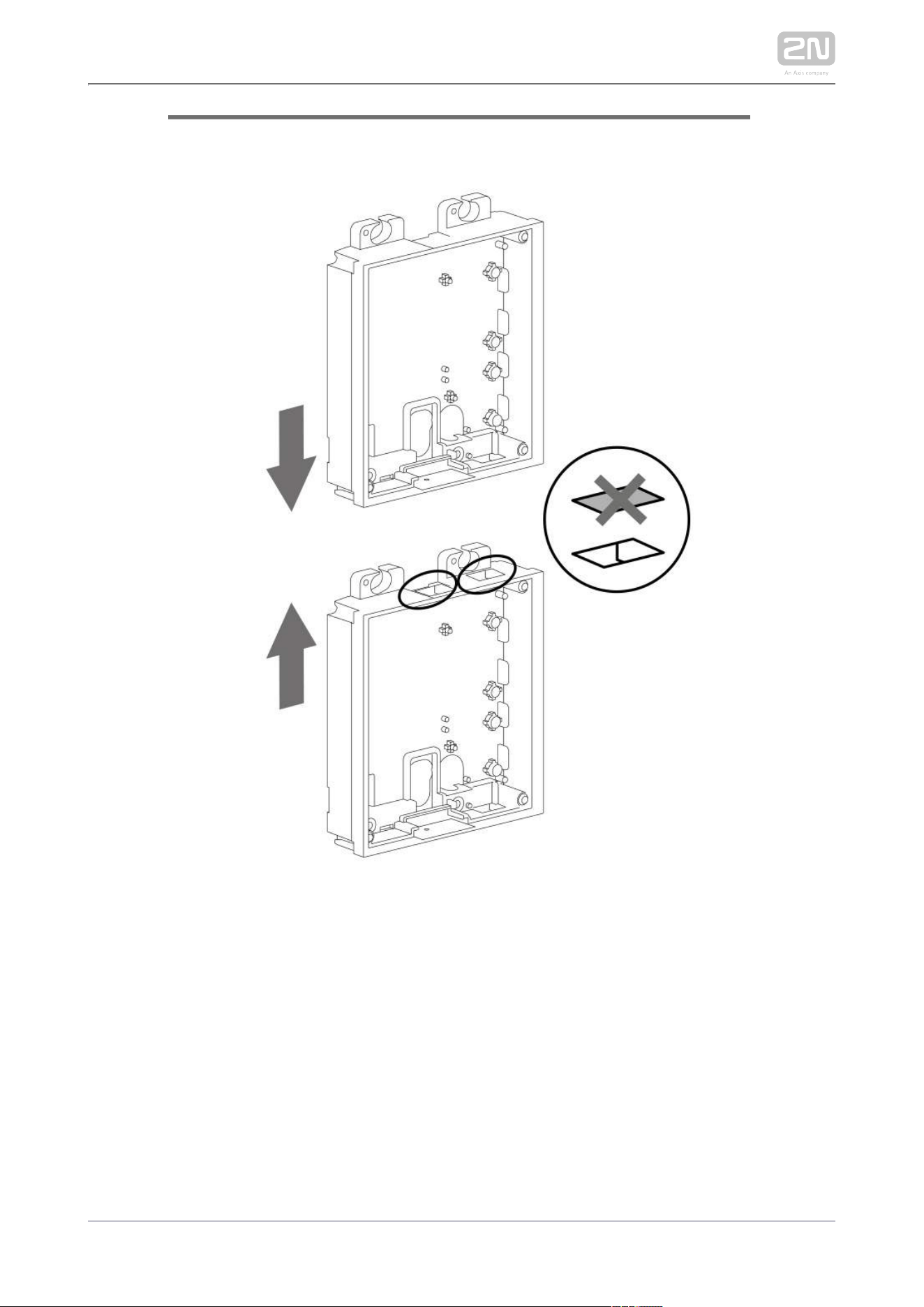
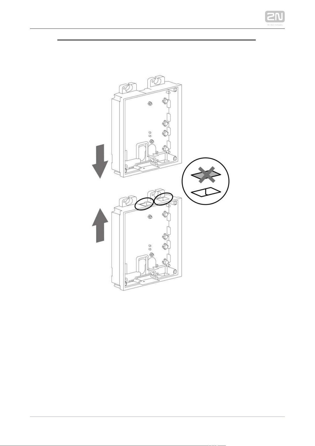
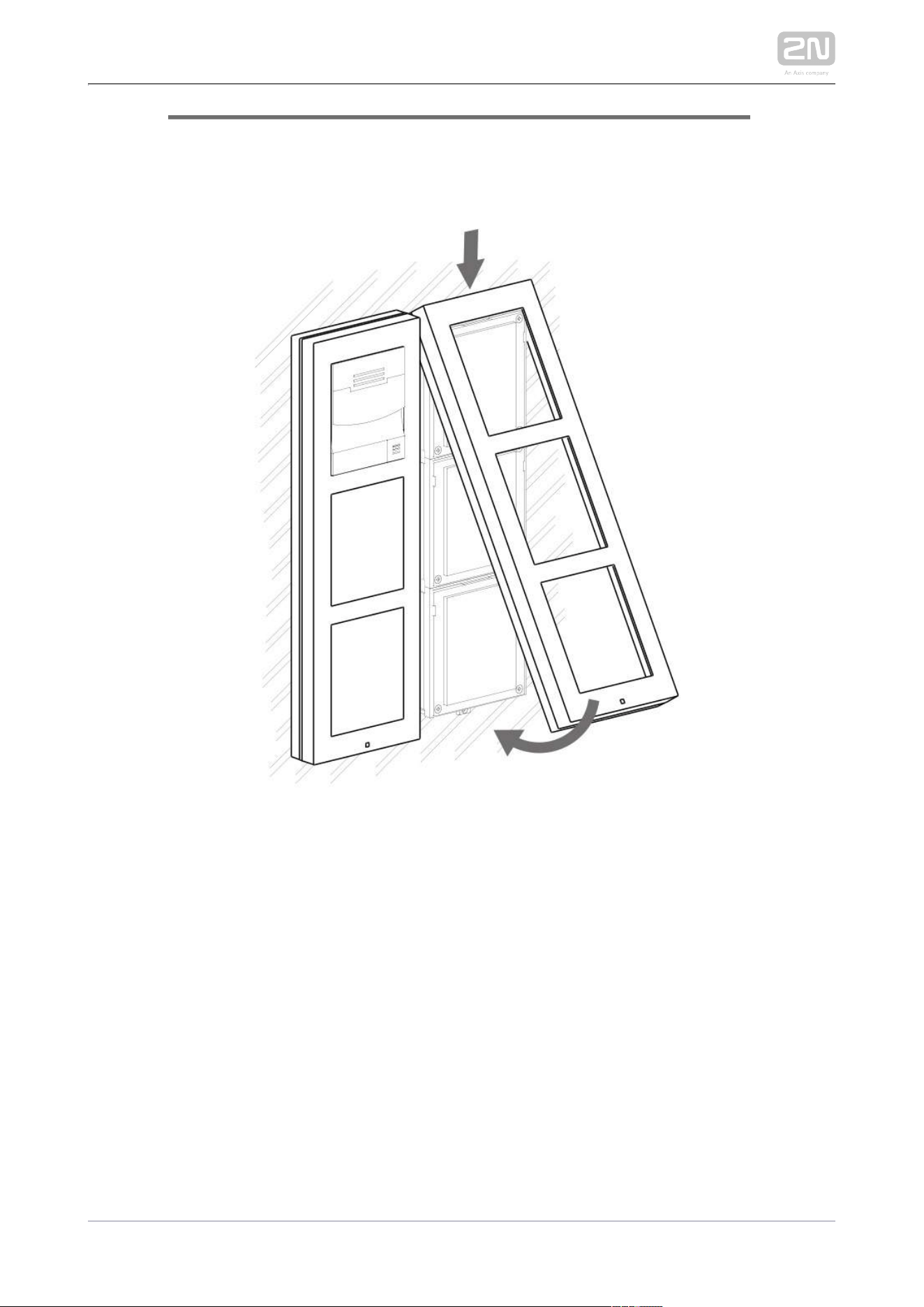
While flush mounting, make sure that the box is installed properly, i.e.
with the box frame on the wall surface. There are snap-off protrusions
on both sides of the flush mounting box to facilitate positioning. Make
sure that the frame is placed precisely onto the flush mounting box off
the wall to provide effective sealing and avoid water penetration into the
intercom. Refer to the pictorial instructions inside the flush mounting
box package.
Any intentional mechanical damage (drilling, main unit tampering, etc.)
results in a loss of warranty.
2N TELEKOMUNIKACE a.s., www.2n.cz 61/319
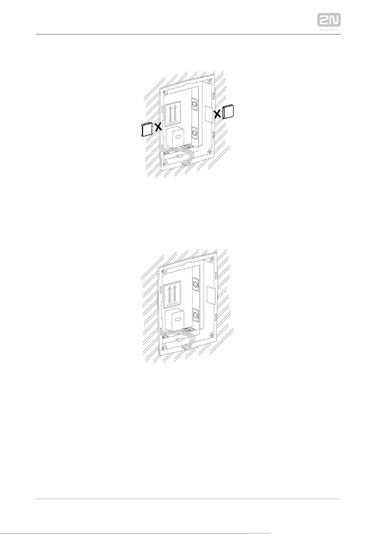
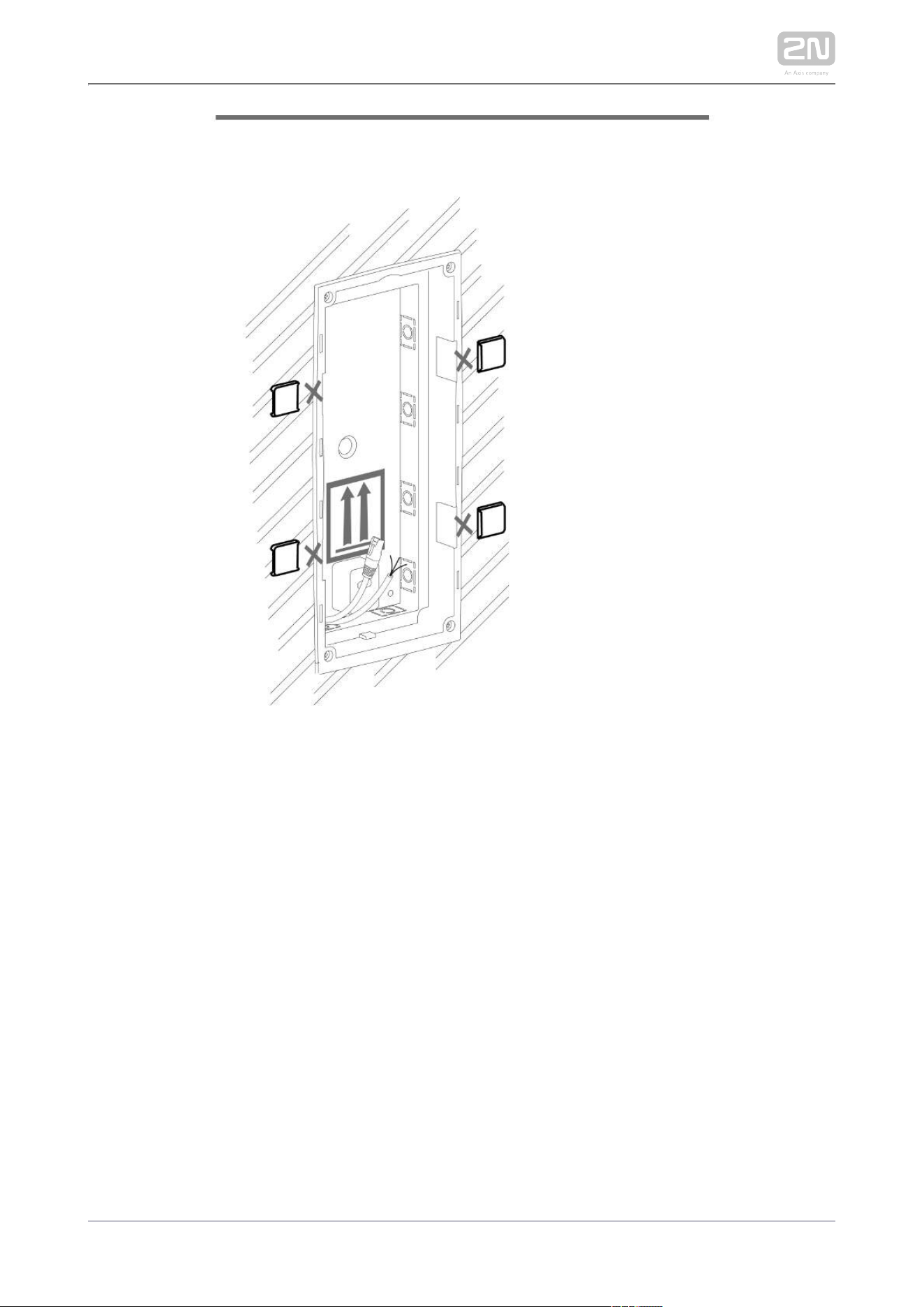
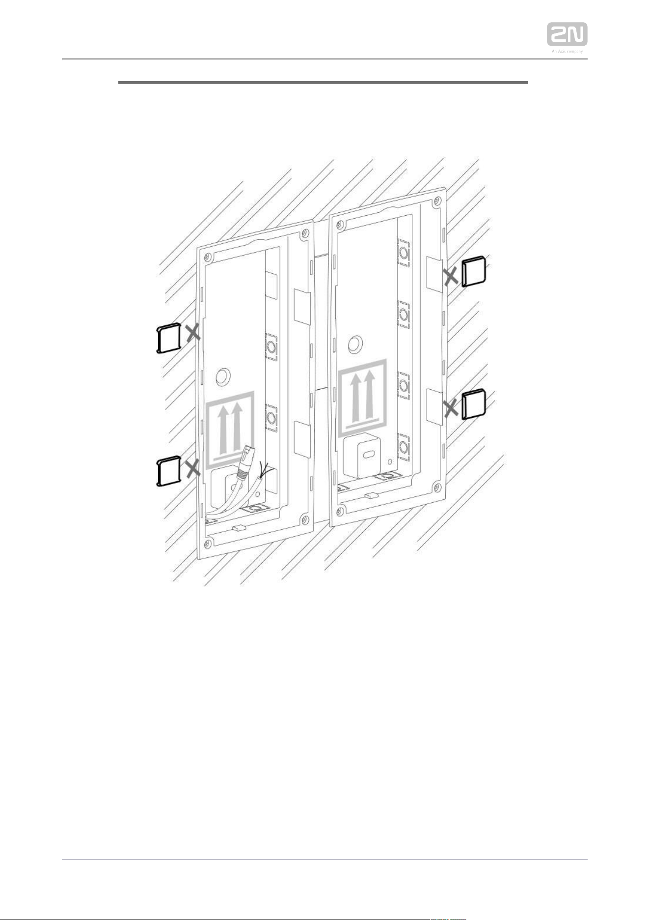
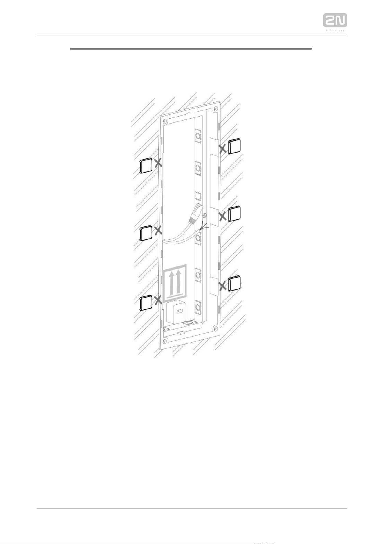
Warning!
It is forbidden to use silicone or any other sealing material on the
marked and hatched places.

2N TELEKOMUNIKACE a.s., www.2n.cz 62/319
Safety
Eliminate the risk of personal injury! Surface mounting is not
recommended for narrow passages or places where people's attention is
distracted by something else. The manufacturer shall not be liable for
injuries in such cases!
Module Installation
2.2.1 One Module Box
2.2.2 Two Modules Box
2.2.3 More Two Module Boxes
2.2.4 Three Modules Boxes
2.2.5 Více krabic pro tři moduly
2.2.6 Tamper and I/O Modules
2.2.7 Module Dimensions
Mounting Backplate Installation
2.2.8 Example of Mounting Plate Installation
2N TELEKOMUNIKACE a.s., www.2n.cz 63/319
2.2.1 One Module Box
Caution
The one-module box is designed for stand-alone installations of
extending modules such as departure readers. A two-module box is
required for the main unit installation.
Flush mounting box mounting – classic bricks
2N TELEKOMUNIKACE a.s., www.2n.cz 64/319
2N TELEKOMUNIKACE a.s., www.2n.cz 65/319

2N TELEKOMUNIKACE a.s., www.2n.cz 66/319
2N TELEKOMUNIKACE a.s., www.2n.cz 67/319
Flush mounting box mounting – plasterboard
2N TELEKOMUNIKACE a.s., www.2n.cz 68/319
2N TELEKOMUNIKACE a.s., www.2n.cz 69/319
2N TELEKOMUNIKACE a.s., www.2n.cz 70/319
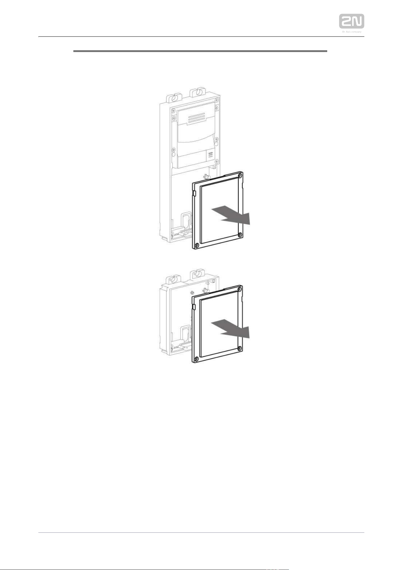
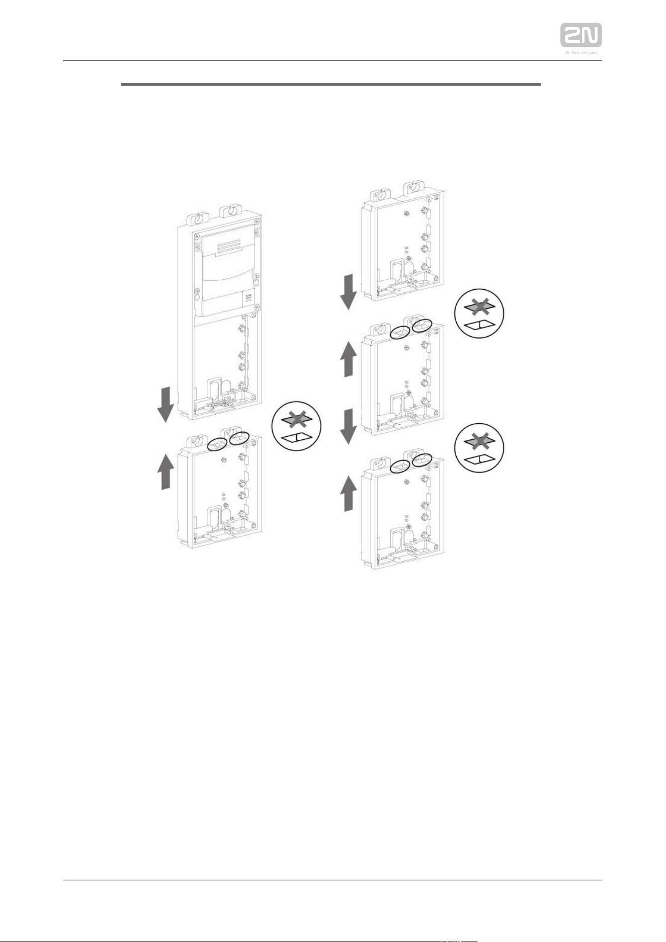
Flush module mounting
2N TELEKOMUNIKACE a.s., www.2n.cz 71/319
2N TELEKOMUNIKACE a.s., www.2n.cz 72/319
2N TELEKOMUNIKACE a.s., www.2n.cz 73/319
2N TELEKOMUNIKACE a.s., www.2n.cz 74/319
2N TELEKOMUNIKACE a.s., www.2n.cz 75/319
Surface module mounting
2N TELEKOMUNIKACE a.s., www.2n.cz 76/319
2N TELEKOMUNIKACE a.s., www.2n.cz 77/319
2N TELEKOMUNIKACE a.s., www.2n.cz 78/319
2N TELEKOMUNIKACE a.s., www.2n.cz 79/319
2N TELEKOMUNIKACE a.s., www.2n.cz 80/319
2.2.2 Two Module Box
Flush mounting box mounting – classic bricks
2N TELEKOMUNIKACE a.s., www.2n.cz 81/319
2N TELEKOMUNIKACE a.s., www.2n.cz 82/319
2N TELEKOMUNIKACE a.s., www.2n.cz 83/319
2N TELEKOMUNIKACE a.s., www.2n.cz 84/319
2N TELEKOMUNIKACE a.s., www.2n.cz 85/319
2N TELEKOMUNIKACE a.s., www.2n.cz 86/319
2N TELEKOMUNIKACE a.s., www.2n.cz 87/319
Flush mounting box mounting – plasterboard

2N TELEKOMUNIKACE a.s., www.2n.cz 88/319
2N TELEKOMUNIKACE a.s., www.2n.cz 89/319
2N TELEKOMUNIKACE a.s., www.2n.cz 90/319
2N TELEKOMUNIKACE a.s., www.2n.cz 91/319
2N TELEKOMUNIKACE a.s., www.2n.cz 92/319
2N TELEKOMUNIKACE a.s., www.2n.cz 93/319
Flush module mounting
2N TELEKOMUNIKACE a.s., www.2n.cz 94/319
2N TELEKOMUNIKACE a.s., www.2n.cz 95/319
2N TELEKOMUNIKACE a.s., www.2n.cz 96/319
2N TELEKOMUNIKACE a.s., www.2n.cz 97/319
2N TELEKOMUNIKACE a.s., www.2n.cz 98/319
2N TELEKOMUNIKACE a.s., www.2n.cz 99/319
2N TELEKOMUNIKACE a.s., www.2n.cz 100/319
2N TELEKOMUNIKACE a.s., www.2n.cz 101/319
2N TELEKOMUNIKACE a.s., www.2n.cz 102/319
2N TELEKOMUNIKACE a.s., www.2n.cz 103/319
Surface module mounting
2N TELEKOMUNIKACE a.s., www.2n.cz 104/319
2N TELEKOMUNIKACE a.s., www.2n.cz 105/319
2N TELEKOMUNIKACE a.s., www.2n.cz 106/319
2N TELEKOMUNIKACE a.s., www.2n.cz 107/319
2N TELEKOMUNIKACE a.s., www.2n.cz 108/319
2N TELEKOMUNIKACE a.s., www.2n.cz 109/319
2N TELEKOMUNIKACE a.s., www.2n.cz 110/319

2N TELEKOMUNIKACE a.s., www.2n.cz 111/319
2N TELEKOMUNIKACE a.s., www.2n.cz 112/319
2N TELEKOMUNIKACE a.s., www.2n.cz 113/319
2.2.3 More Two Module Boxes
Flush mounting box mounting – classic bricks
2N TELEKOMUNIKACE a.s., www.2n.cz 114/319
2N TELEKOMUNIKACE a.s., www.2n.cz 115/319
2N TELEKOMUNIKACE a.s., www.2n.cz 116/319

2N TELEKOMUNIKACE a.s., www.2n.cz 117/319
2N TELEKOMUNIKACE a.s., www.2n.cz 118/319
2N TELEKOMUNIKACE a.s., www.2n.cz 119/319
2N TELEKOMUNIKACE a.s., www.2n.cz 120/319
2N TELEKOMUNIKACE a.s., www.2n.cz 121/319
2N TELEKOMUNIKACE a.s., www.2n.cz 122/319
Flush mounting box mounting – plasterboard
2N TELEKOMUNIKACE a.s., www.2n.cz 123/319
2N TELEKOMUNIKACE a.s., www.2n.cz 124/319
2N TELEKOMUNIKACE a.s., www.2n.cz 125/319
2N TELEKOMUNIKACE a.s., www.2n.cz 126/319
2N TELEKOMUNIKACE a.s., www.2n.cz 127/319
2N TELEKOMUNIKACE a.s., www.2n.cz 128/319
2N TELEKOMUNIKACE a.s., www.2n.cz 129/319
2N TELEKOMUNIKACE a.s., www.2n.cz 130/319
Flush module mounting
2N TELEKOMUNIKACE a.s., www.2n.cz 131/319
2N TELEKOMUNIKACE a.s., www.2n.cz 132/319
2N TELEKOMUNIKACE a.s., www.2n.cz 133/319
2N TELEKOMUNIKACE a.s., www.2n.cz 134/319
2N TELEKOMUNIKACE a.s., www.2n.cz 135/319
2N TELEKOMUNIKACE a.s., www.2n.cz 136/319
2N TELEKOMUNIKACE a.s., www.2n.cz 137/319
2N TELEKOMUNIKACE a.s., www.2n.cz 138/319
2N TELEKOMUNIKACE a.s., www.2n.cz 139/319
2N TELEKOMUNIKACE a.s., www.2n.cz 140/319
2N TELEKOMUNIKACE a.s., www.2n.cz 141/319
2N TELEKOMUNIKACE a.s., www.2n.cz 142/319
2N TELEKOMUNIKACE a.s., www.2n.cz 143/319
Surface module mounting
2N TELEKOMUNIKACE a.s., www.2n.cz 144/319
2N TELEKOMUNIKACE a.s., www.2n.cz 145/319
2N TELEKOMUNIKACE a.s., www.2n.cz 146/319
2N TELEKOMUNIKACE a.s., www.2n.cz 147/319
2N TELEKOMUNIKACE a.s., www.2n.cz 148/319
2N TELEKOMUNIKACE a.s., www.2n.cz 149/319
2N TELEKOMUNIKACE a.s., www.2n.cz 150/319
2N TELEKOMUNIKACE a.s., www.2n.cz 151/319
2N TELEKOMUNIKACE a.s., www.2n.cz 152/319
2N TELEKOMUNIKACE a.s., www.2n.cz 153/319
2N TELEKOMUNIKACE a.s., www.2n.cz 154/319
2N TELEKOMUNIKACE a.s., www.2n.cz 155/319
2.2.4 Three Module Box
Flush mounting box mounting – classic bricks
2N TELEKOMUNIKACE a.s., www.2n.cz 156/319
2N TELEKOMUNIKACE a.s., www.2n.cz 157/319
2N TELEKOMUNIKACE a.s., www.2n.cz 158/319
2N TELEKOMUNIKACE a.s., www.2n.cz 159/319
2N TELEKOMUNIKACE a.s., www.2n.cz 160/319
2N TELEKOMUNIKACE a.s., www.2n.cz 161/319
2N TELEKOMUNIKACE a.s., www.2n.cz 162/319
Flush mounting box mounting – plasterboard
2N TELEKOMUNIKACE a.s., www.2n.cz 163/319
2N TELEKOMUNIKACE a.s., www.2n.cz 164/319
2N TELEKOMUNIKACE a.s., www.2n.cz 165/319
2N TELEKOMUNIKACE a.s., www.2n.cz 166/319
2N TELEKOMUNIKACE a.s., www.2n.cz 167/319
2N TELEKOMUNIKACE a.s., www.2n.cz 168/319
Flush module mounting
2N TELEKOMUNIKACE a.s., www.2n.cz 169/319
2N TELEKOMUNIKACE a.s., www.2n.cz 170/319
2N TELEKOMUNIKACE a.s., www.2n.cz 171/319
2N TELEKOMUNIKACE a.s., www.2n.cz 172/319
2N TELEKOMUNIKACE a.s., www.2n.cz 173/319
2N TELEKOMUNIKACE a.s., www.2n.cz 174/319
2N TELEKOMUNIKACE a.s., www.2n.cz 175/319
2N TELEKOMUNIKACE a.s., www.2n.cz 176/319
2N TELEKOMUNIKACE a.s., www.2n.cz 177/319
2N TELEKOMUNIKACE a.s., www.2n.cz 178/319
2N TELEKOMUNIKACE a.s., www.2n.cz 179/319
2N TELEKOMUNIKACE a.s., www.2n.cz 180/319
2N TELEKOMUNIKACE a.s., www.2n.cz 181/319
Surface module mounting
2N TELEKOMUNIKACE a.s., www.2n.cz 182/319
2N TELEKOMUNIKACE a.s., www.2n.cz 183/319
2N TELEKOMUNIKACE a.s., www.2n.cz 184/319
2N TELEKOMUNIKACE a.s., www.2n.cz 185/319
2N TELEKOMUNIKACE a.s., www.2n.cz 186/319
2N TELEKOMUNIKACE a.s., www.2n.cz 187/319
2N TELEKOMUNIKACE a.s., www.2n.cz 188/319
2N TELEKOMUNIKACE a.s., www.2n.cz 189/319
2N TELEKOMUNIKACE a.s., www.2n.cz 190/319
2N TELEKOMUNIKACE a.s., www.2n.cz 191/319
2N TELEKOMUNIKACE a.s., www.2n.cz 192/319
2N TELEKOMUNIKACE a.s., www.2n.cz 193/319
2N TELEKOMUNIKACE a.s., www.2n.cz 194/319
2N TELEKOMUNIKACE a.s., www.2n.cz 195/319
2.2.5 More Three Module Boxes
Flush mounting box mounting – classic bricks
2N TELEKOMUNIKACE a.s., www.2n.cz 196/319
2N TELEKOMUNIKACE a.s., www.2n.cz 197/319
2N TELEKOMUNIKACE a.s., www.2n.cz 198/319
2N TELEKOMUNIKACE a.s., www.2n.cz 199/319
2N TELEKOMUNIKACE a.s., www.2n.cz 200/319
2N TELEKOMUNIKACE a.s., www.2n.cz 201/319
2N TELEKOMUNIKACE a.s., www.2n.cz 202/319
2N TELEKOMUNIKACE a.s., www.2n.cz 203/319
2N TELEKOMUNIKACE a.s., www.2n.cz 204/319
Flush mounting box mounting – plasterboard
2N TELEKOMUNIKACE a.s., www.2n.cz 205/319
2N TELEKOMUNIKACE a.s., www.2n.cz 206/319
2N TELEKOMUNIKACE a.s., www.2n.cz 207/319
2N TELEKOMUNIKACE a.s., www.2n.cz 208/319
2N TELEKOMUNIKACE a.s., www.2n.cz 209/319
2N TELEKOMUNIKACE a.s., www.2n.cz 210/319
2N TELEKOMUNIKACE a.s., www.2n.cz 211/319
2N TELEKOMUNIKACE a.s., www.2n.cz 212/319
Flush module mounting
2N TELEKOMUNIKACE a.s., www.2n.cz 213/319
2N TELEKOMUNIKACE a.s., www.2n.cz 214/319
2N TELEKOMUNIKACE a.s., www.2n.cz 215/319
2N TELEKOMUNIKACE a.s., www.2n.cz 216/319
2N TELEKOMUNIKACE a.s., www.2n.cz 217/319
2N TELEKOMUNIKACE a.s., www.2n.cz 218/319
2N TELEKOMUNIKACE a.s., www.2n.cz 219/319
2N TELEKOMUNIKACE a.s., www.2n.cz 220/319
2N TELEKOMUNIKACE a.s., www.2n.cz 221/319
2N TELEKOMUNIKACE a.s., www.2n.cz 222/319
2N TELEKOMUNIKACE a.s., www.2n.cz 223/319
2N TELEKOMUNIKACE a.s., www.2n.cz 224/319
2N TELEKOMUNIKACE a.s., www.2n.cz 225/319
2N TELEKOMUNIKACE a.s., www.2n.cz 226/319
2N TELEKOMUNIKACE a.s., www.2n.cz 227/319
Surface module mounting
2N TELEKOMUNIKACE a.s., www.2n.cz 228/319
2N TELEKOMUNIKACE a.s., www.2n.cz 229/319
2N TELEKOMUNIKACE a.s., www.2n.cz 230/319

2N TELEKOMUNIKACE a.s., www.2n.cz 231/319
2N TELEKOMUNIKACE a.s., www.2n.cz 232/319
2N TELEKOMUNIKACE a.s., www.2n.cz 233/319
2N TELEKOMUNIKACE a.s., www.2n.cz 234/319
2N TELEKOMUNIKACE a.s., www.2n.cz 235/319
2N TELEKOMUNIKACE a.s., www.2n.cz 236/319
2N TELEKOMUNIKACE a.s., www.2n.cz 237/319
2N TELEKOMUNIKACE a.s., www.2n.cz 238/319
2N TELEKOMUNIKACE a.s., www.2n.cz 239/319
2N TELEKOMUNIKACE a.s., www.2n.cz 240/319
2N TELEKOMUNIKACE a.s., www.2n.cz 241/319
2.2.6 Tamper and I/O Modules
2N TELEKOMUNIKACE a.s., www.2n.cz 242/319

2N TELEKOMUNIKACE a.s., www.2n.cz 243/319
2.2.7 Module Dimensions
Frames
9155011 – Flush mounting frame, 1 module
9155012 – Flush mounting frame, 2 modules
9155013 – Flush mounting frame, 3 modules
9155021 – Surface mounting frame, 1 module
9155022 – Surface mounting frame, 2 modules
9155023 – Surface mounting frame, 3 modules
Backplates
9155061 – 1 module
9155062 – 2 modules
9155063 – 3 modules
9155064 – 2x2 modules
9155065 – 3x2 modules
9155066 – 2x3 modules
9155067 – 3x3 modules
2N TELEKOMUNIKACE a.s., www.2n.cz 244/319
2.2.8 Example of Mounting Plate Installation
Wall installation
2N TELEKOMUNIKACE a.s., www.2n.cz 245/319
2N TELEKOMUNIKACE a.s., www.2n.cz 246/319
2N TELEKOMUNIKACE a.s., www.2n.cz 247/319
Glass surface installation
2N TELEKOMUNIKACE a.s., www.2n.cz 248/319
2N TELEKOMUNIKACE a.s., www.2n.cz 249/319

2N TELEKOMUNIKACE a.s., www.2n.cz 250/319
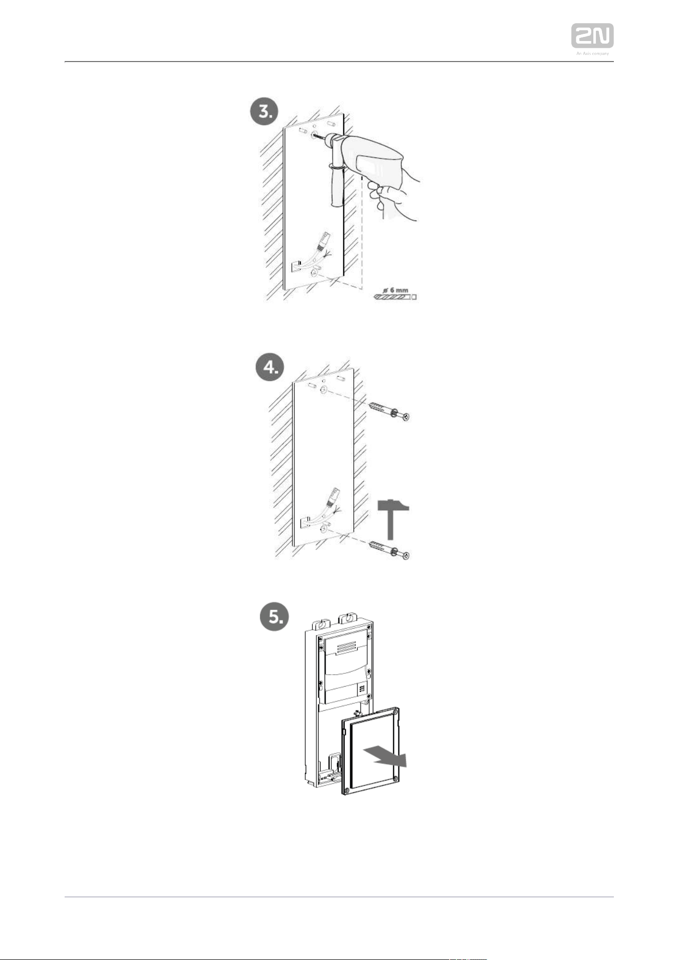
1.
2.
1.
2.
1.
2.
3.
4.
5.
6.
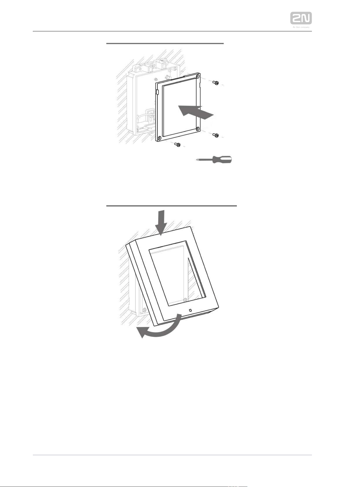
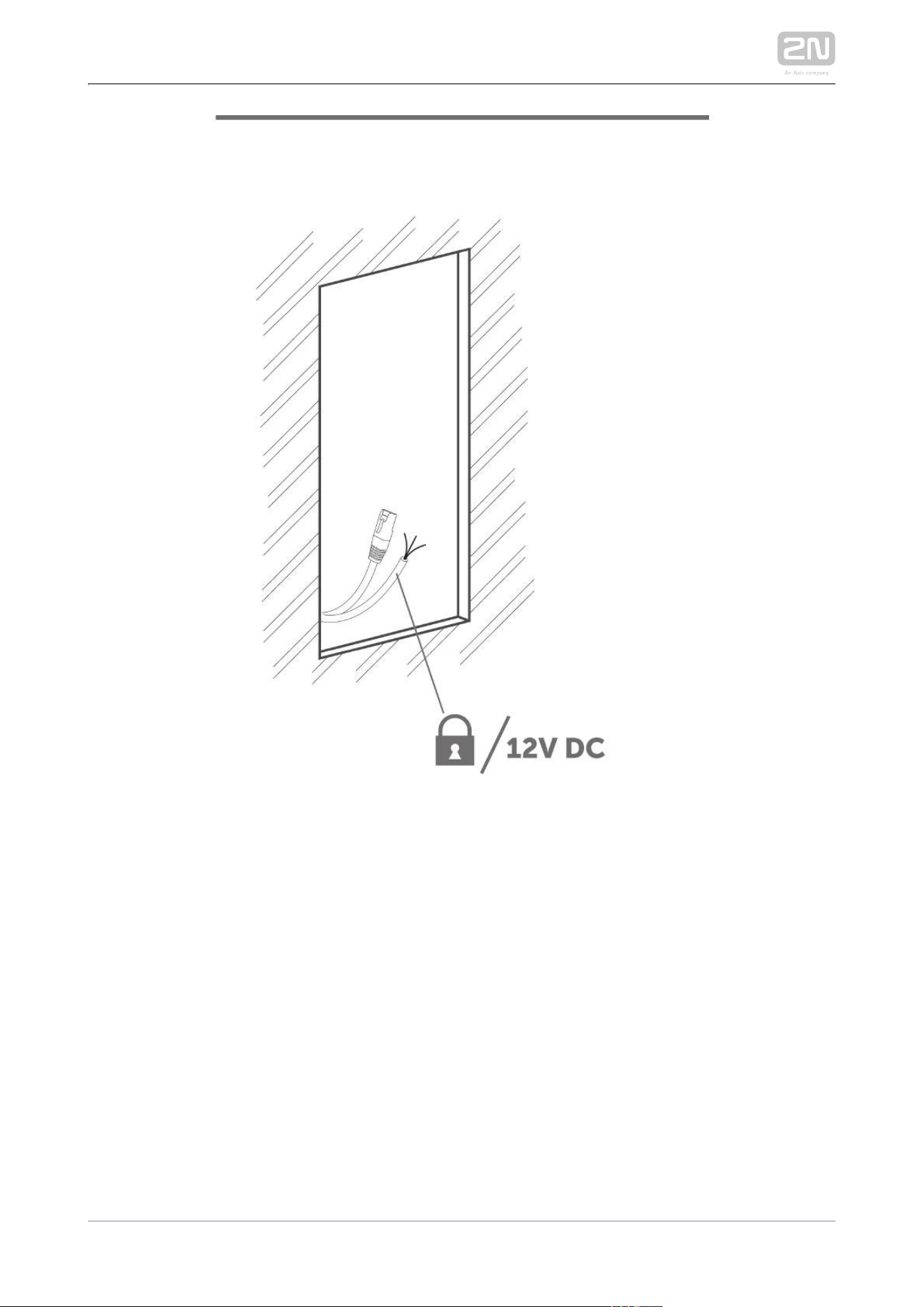
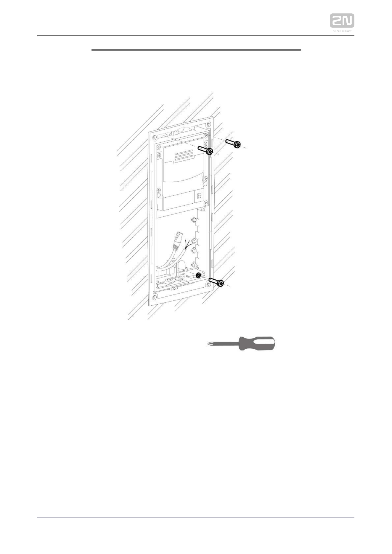
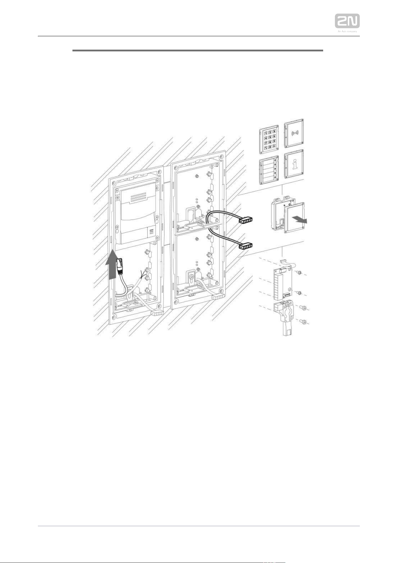
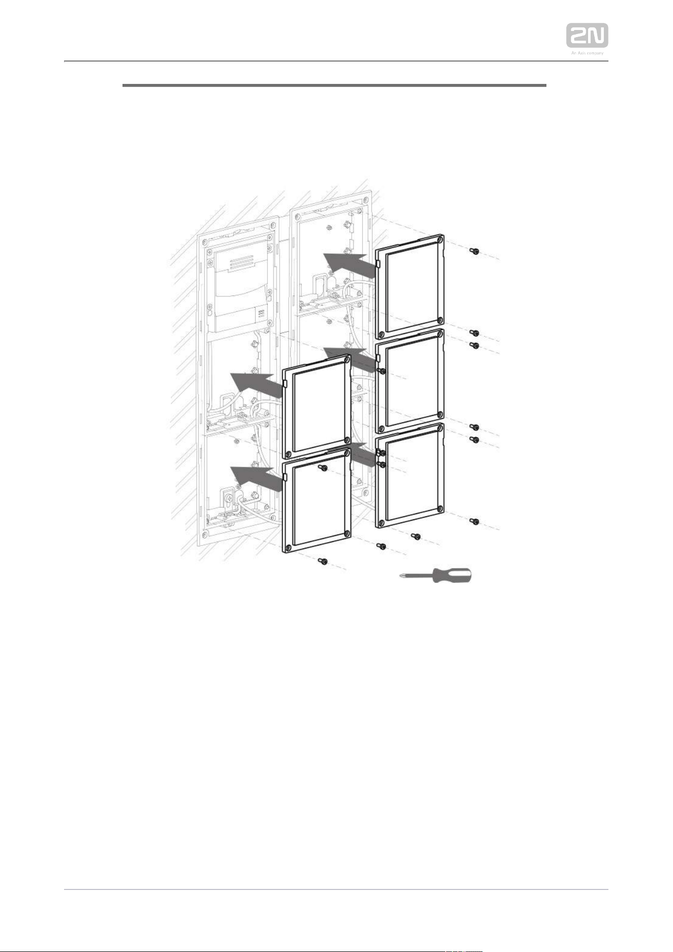
2.3 Electric Installation
This subsection describes how to install the modules, how to connect the 2N IP
®
main unit to the power supply and LAN and how to connect other elements.Verso
Caution
The device must be part of the electrical system of the building.
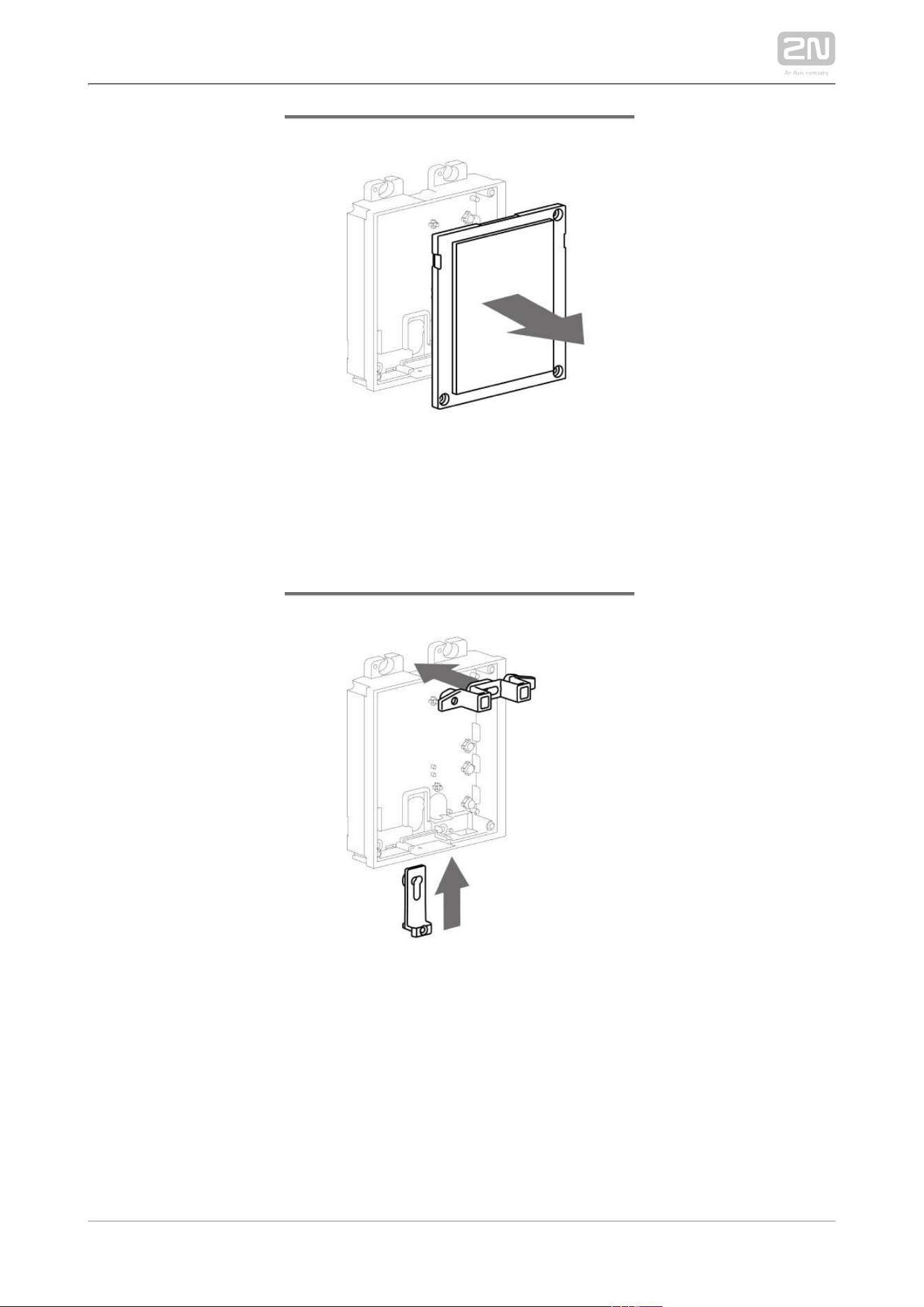
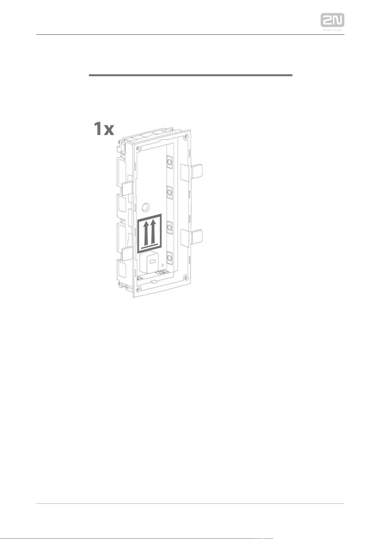
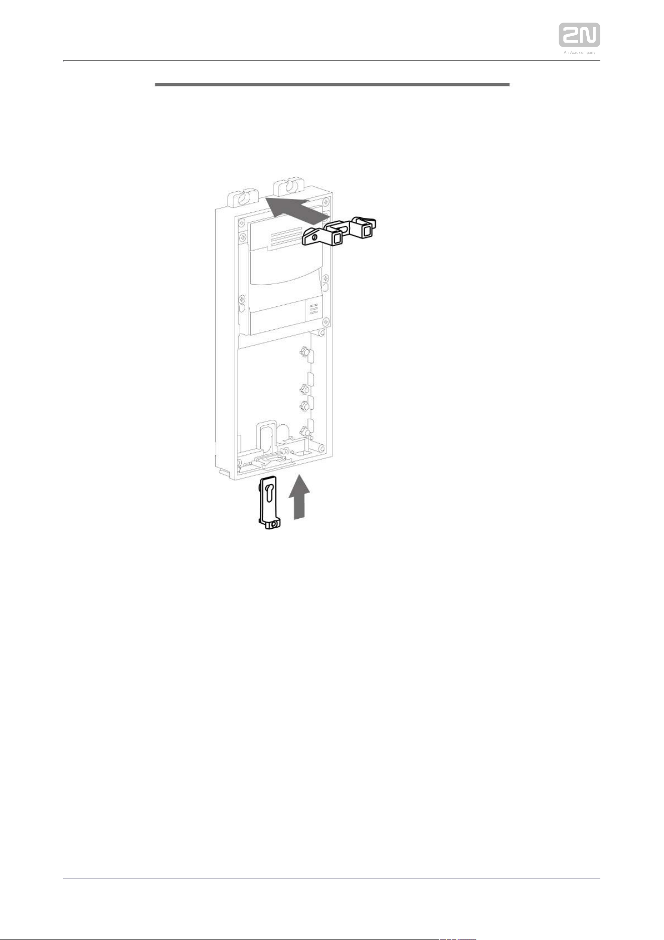
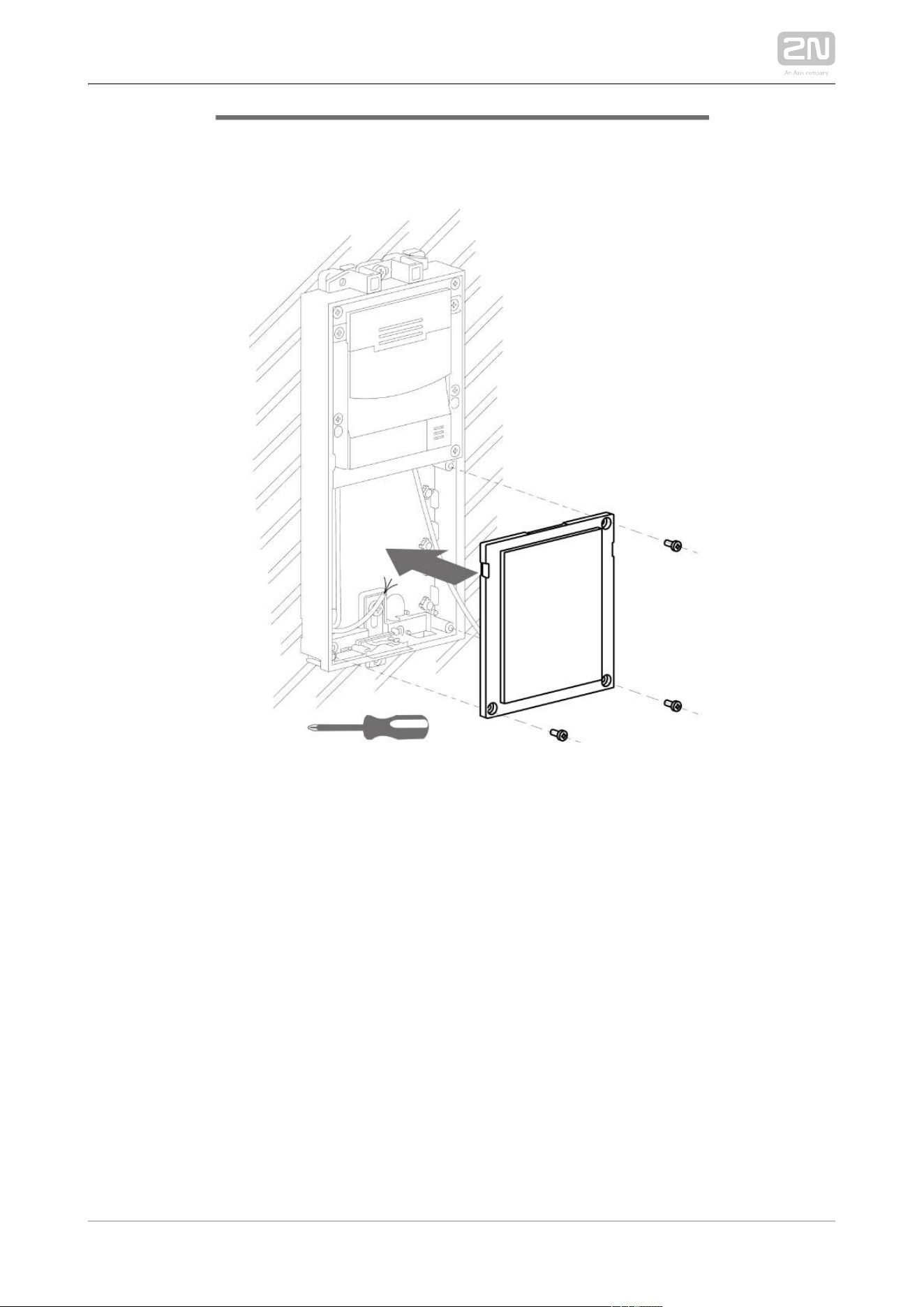
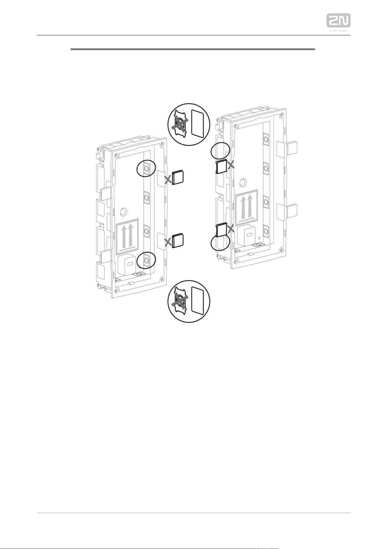
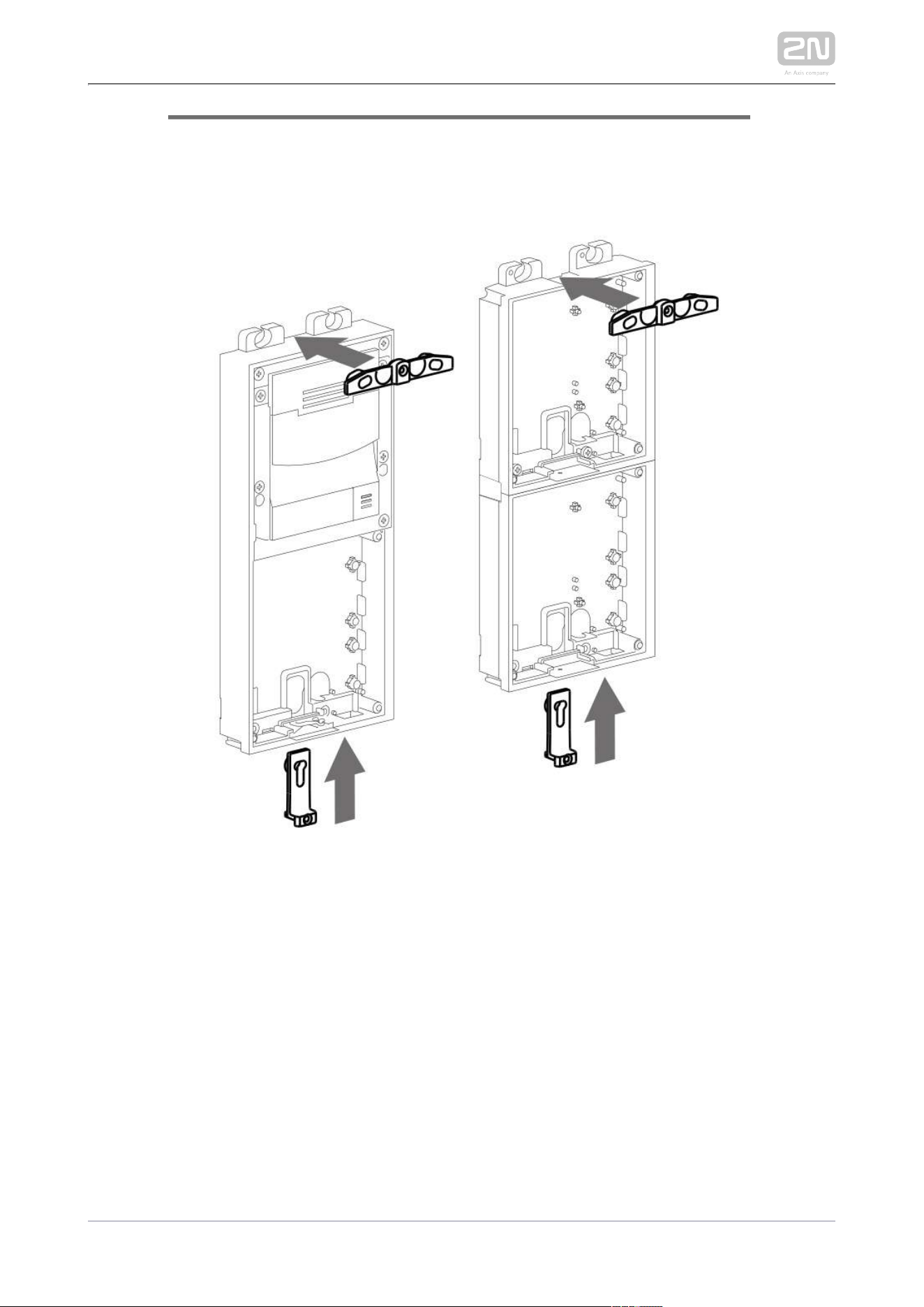
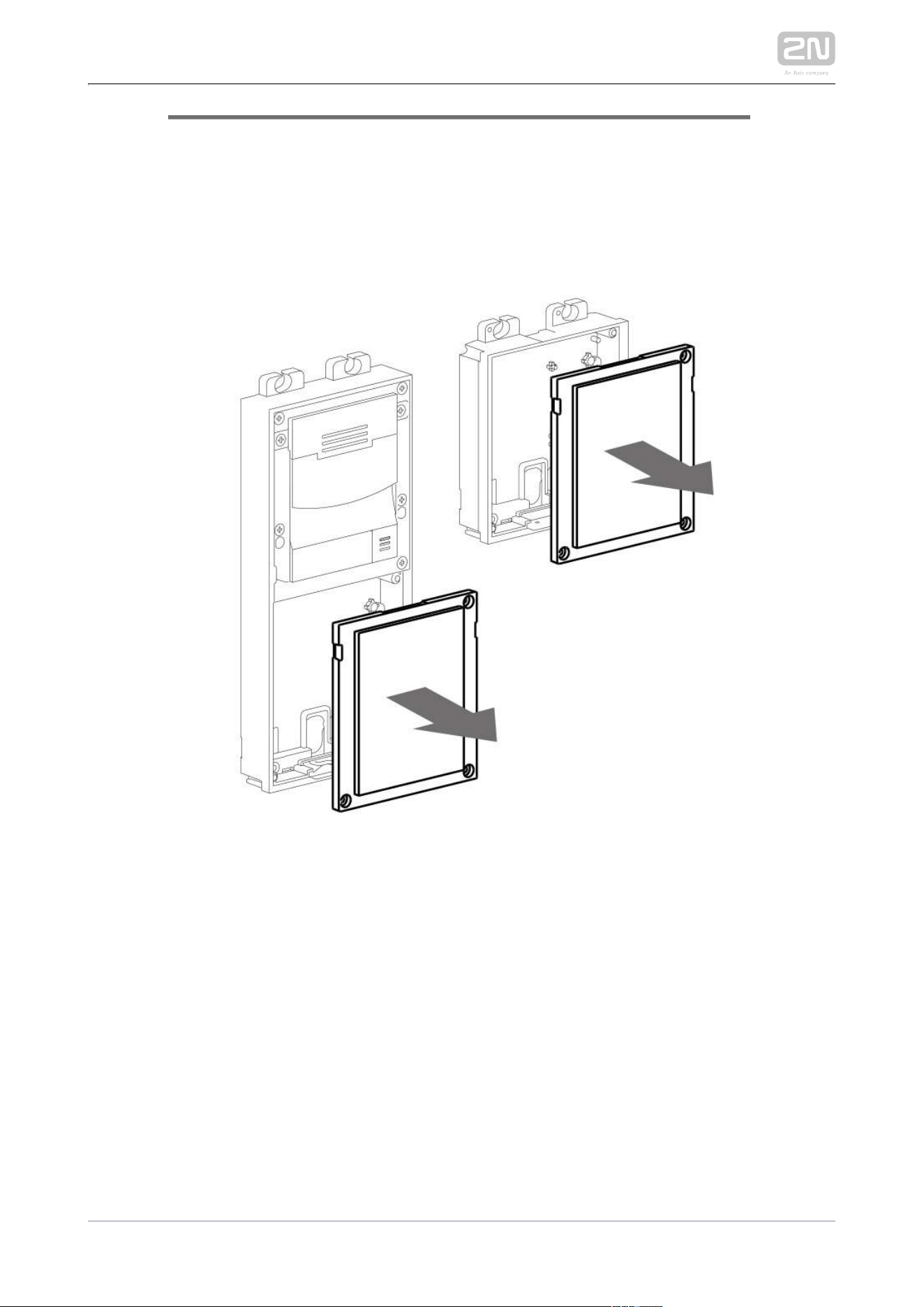
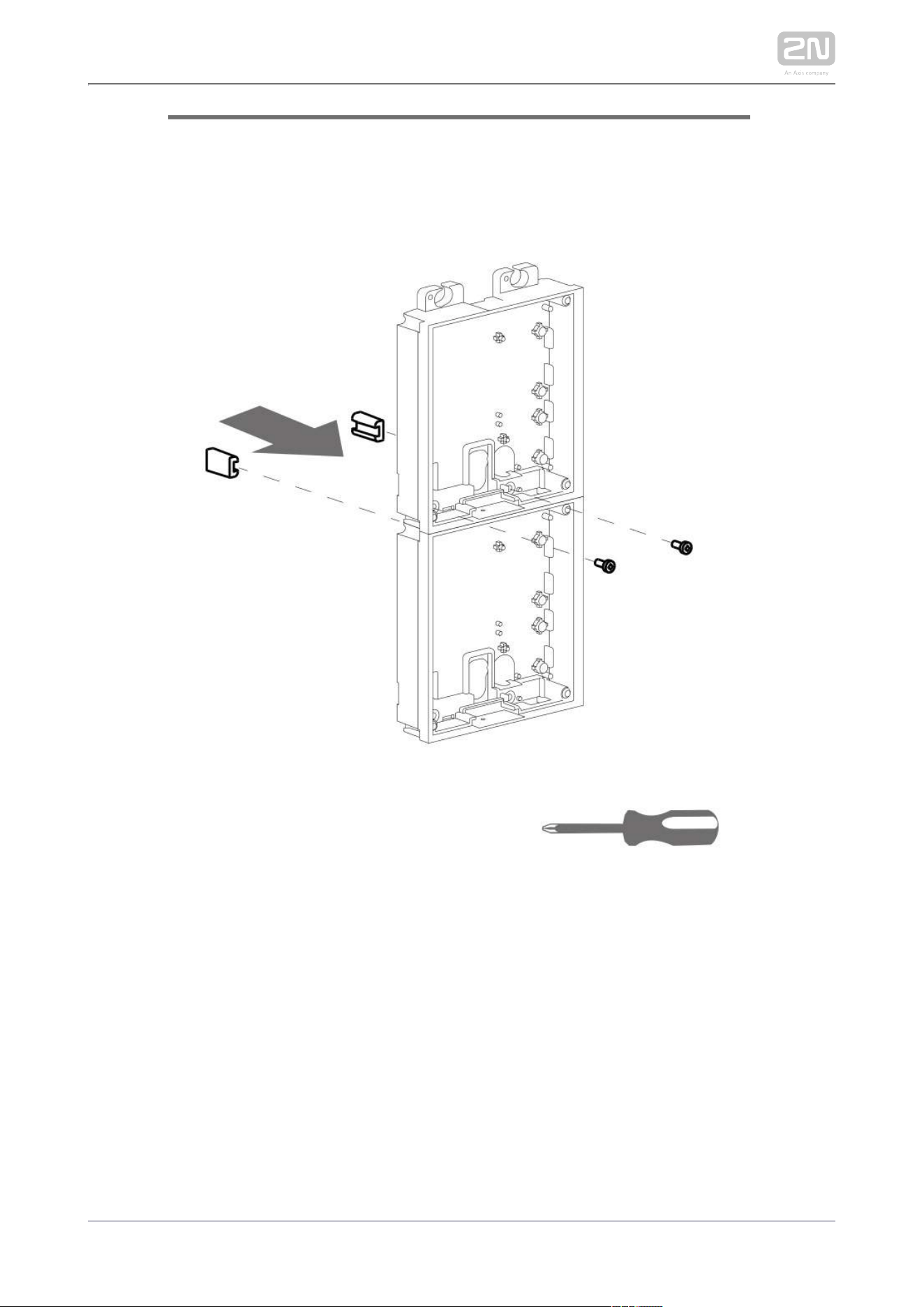
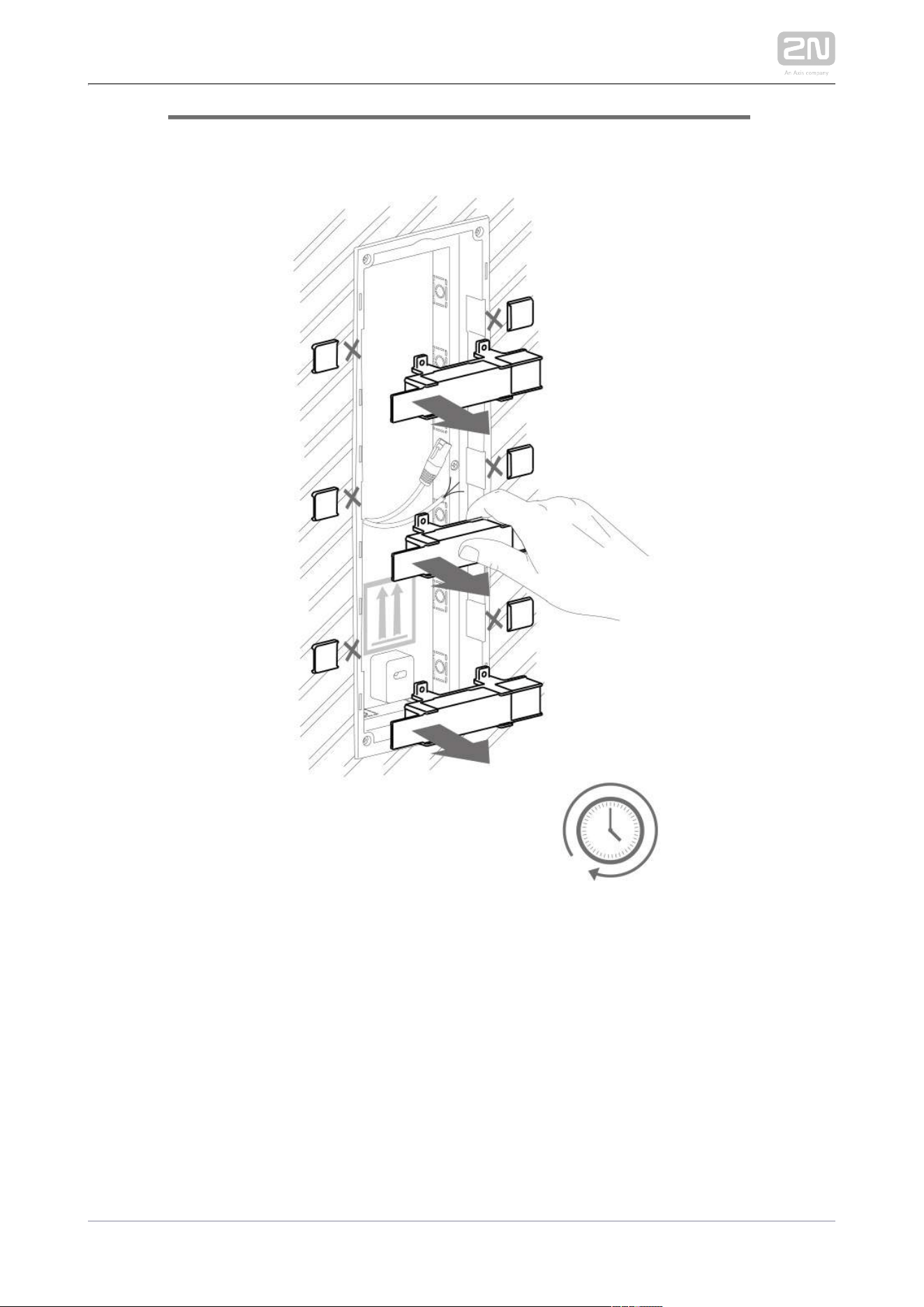
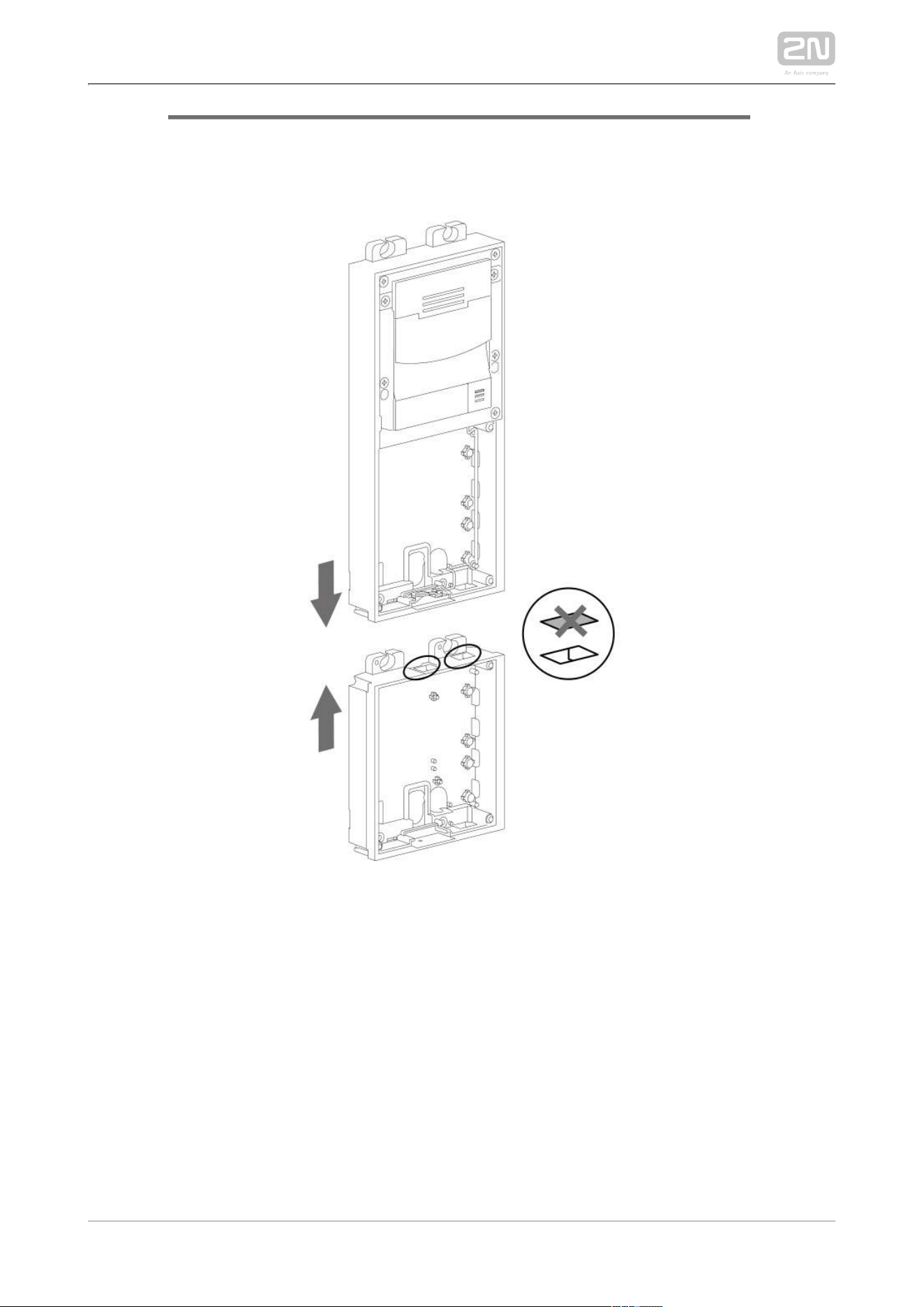
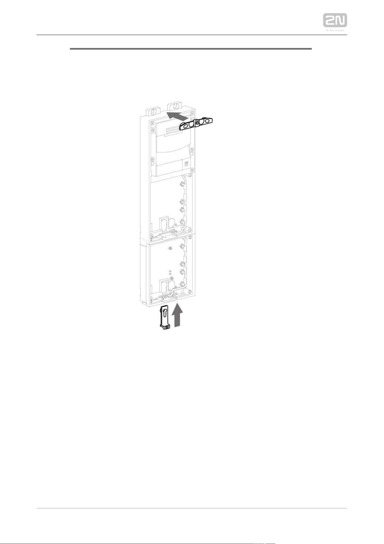
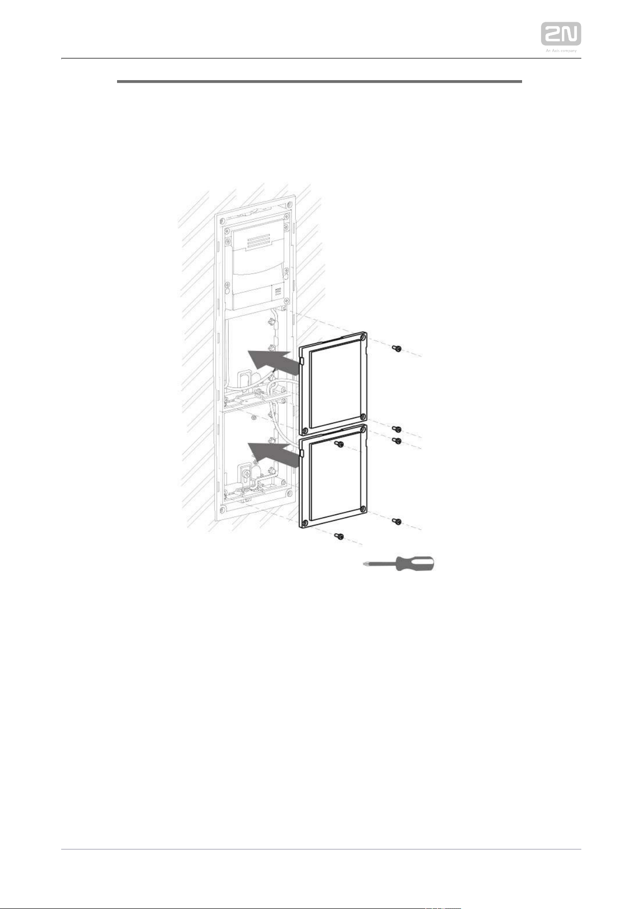
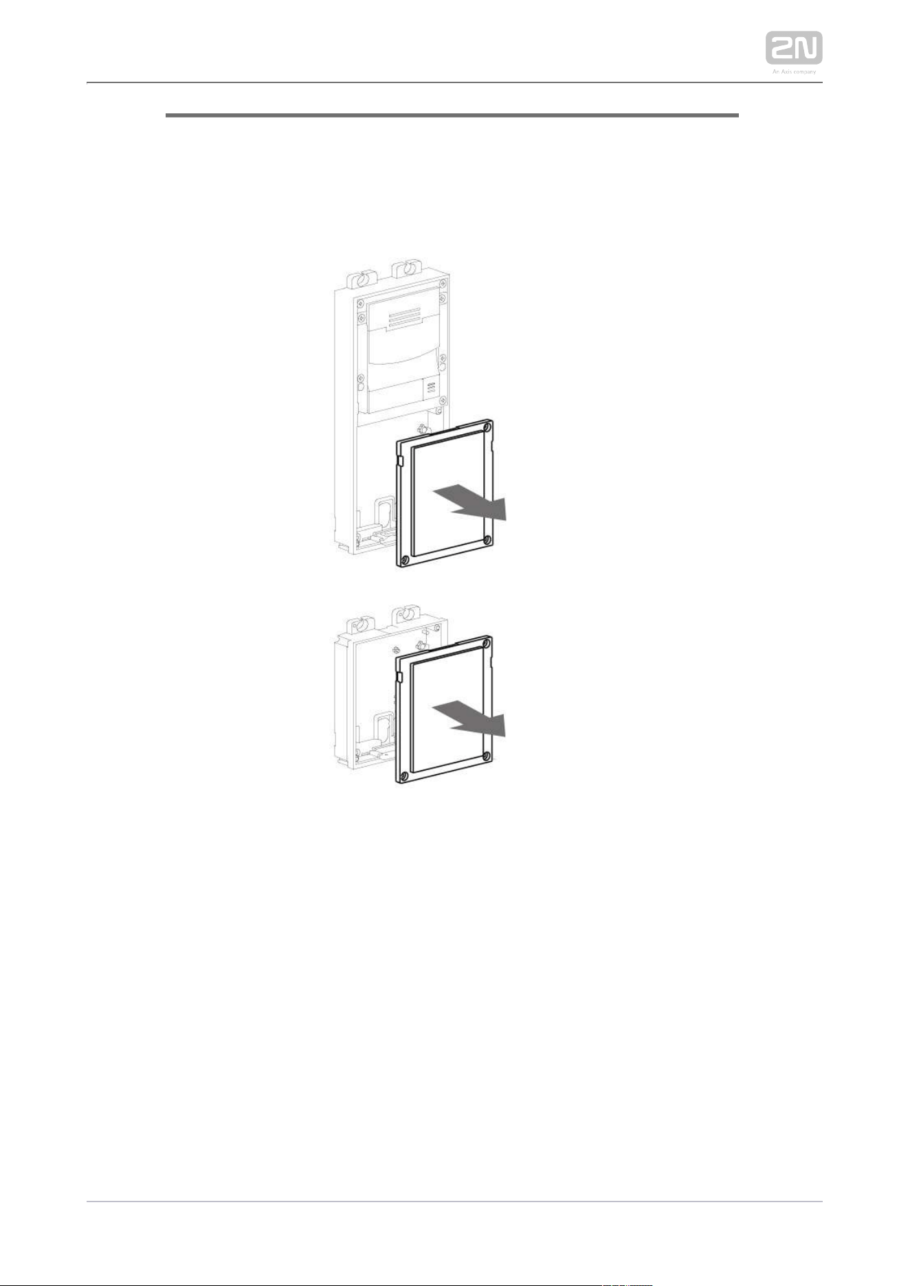
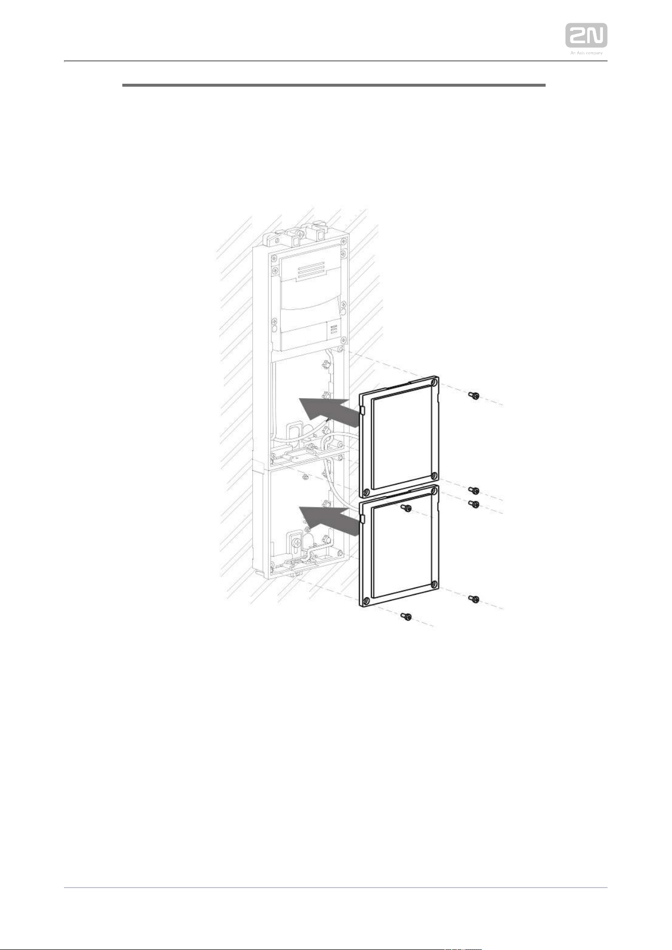
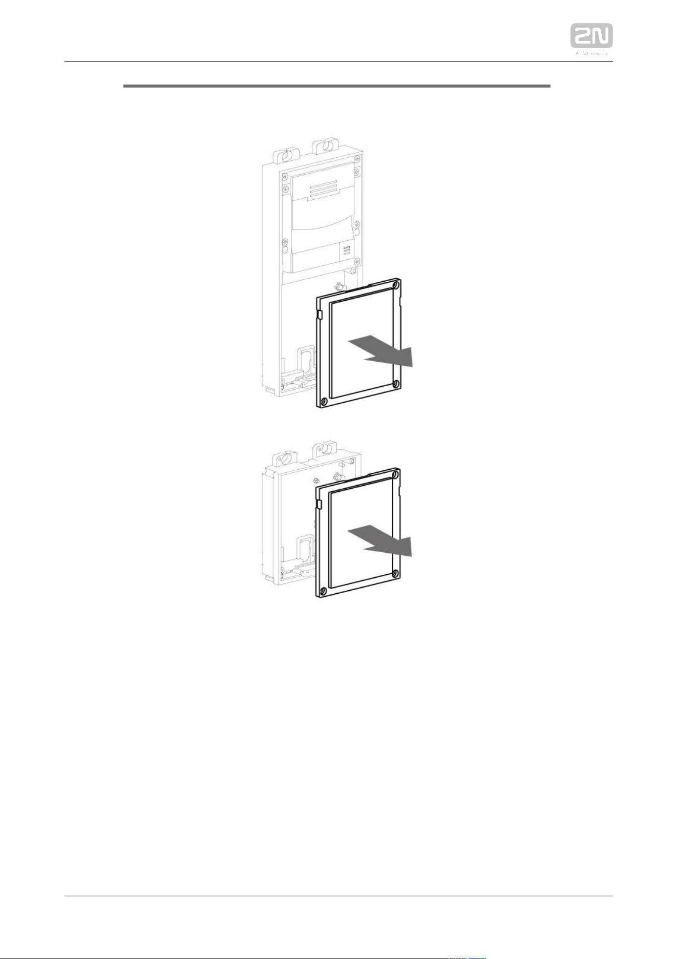
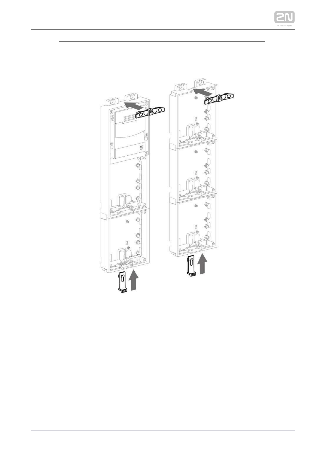
Mounting Preparation
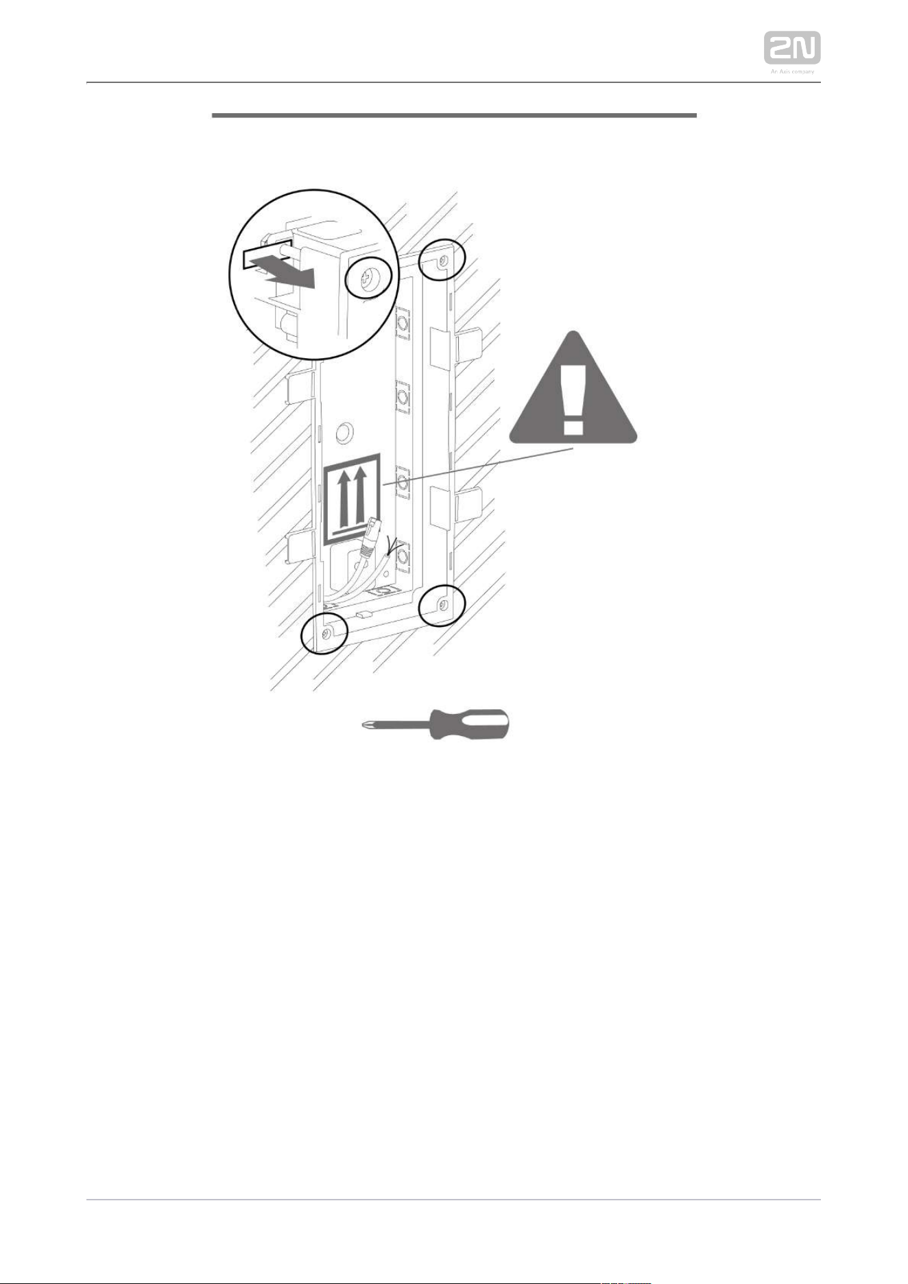
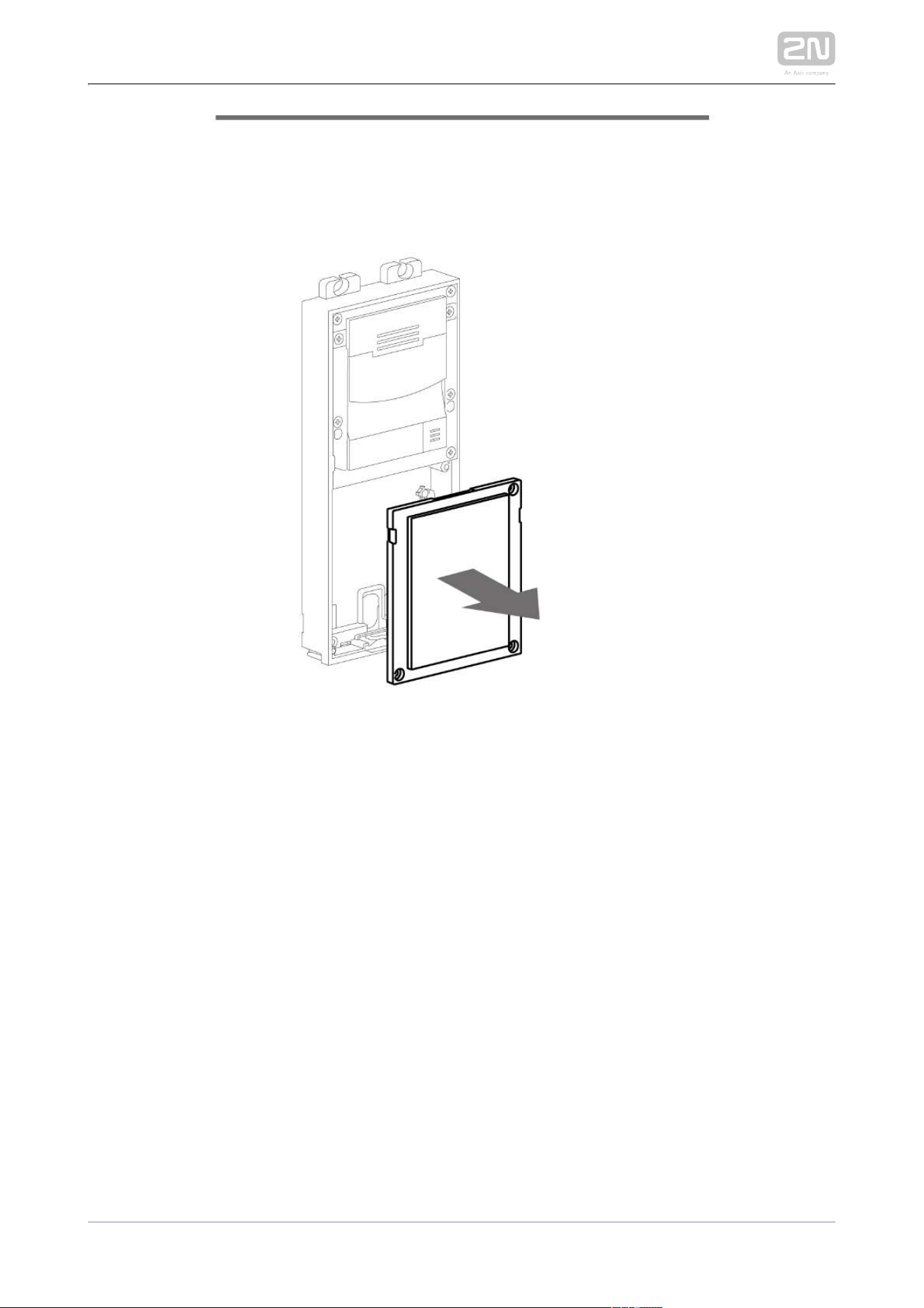
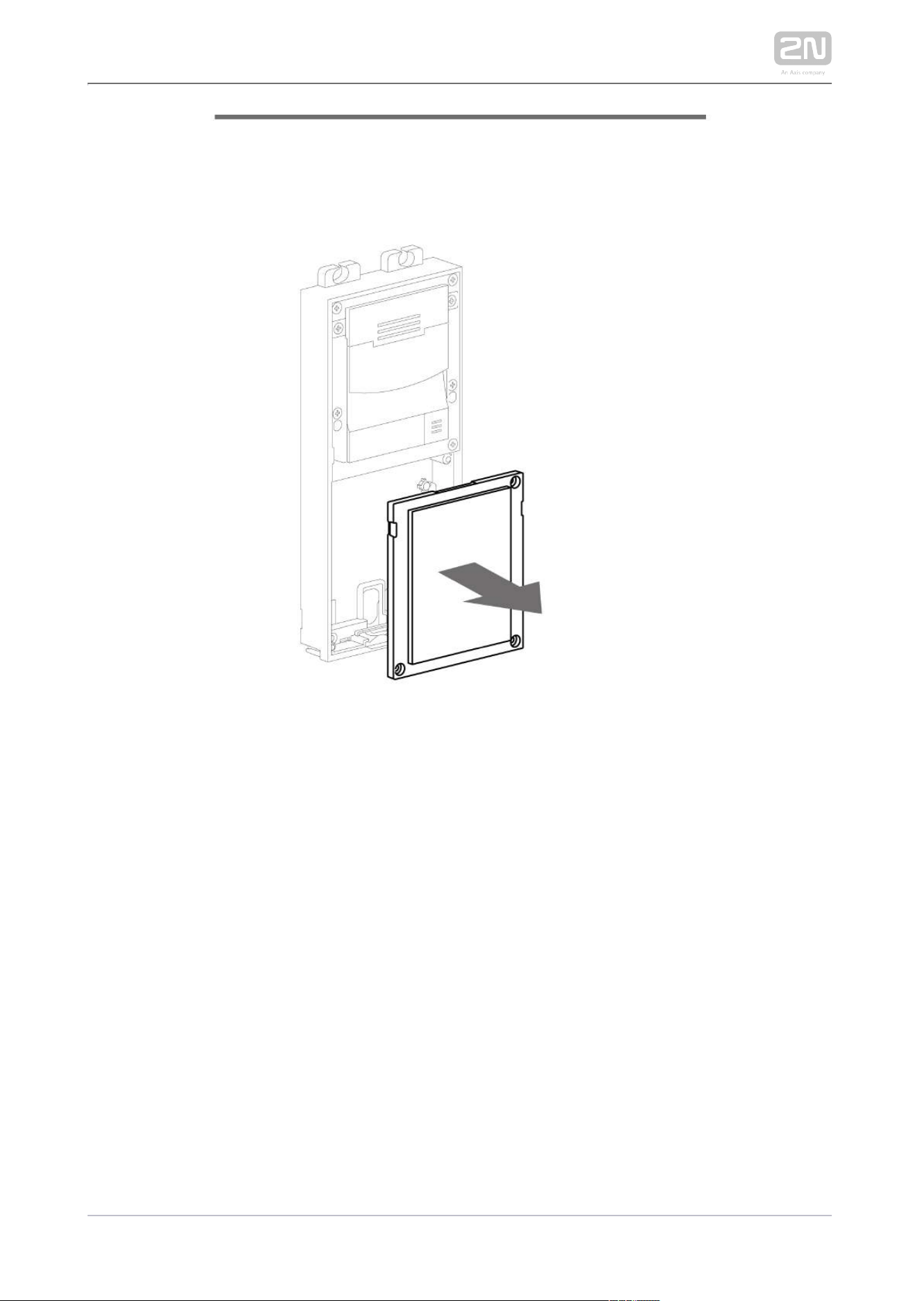
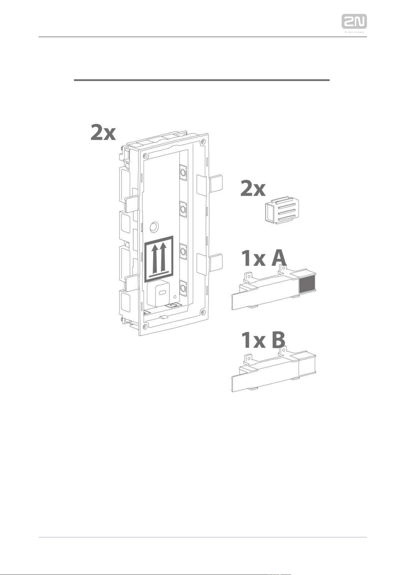
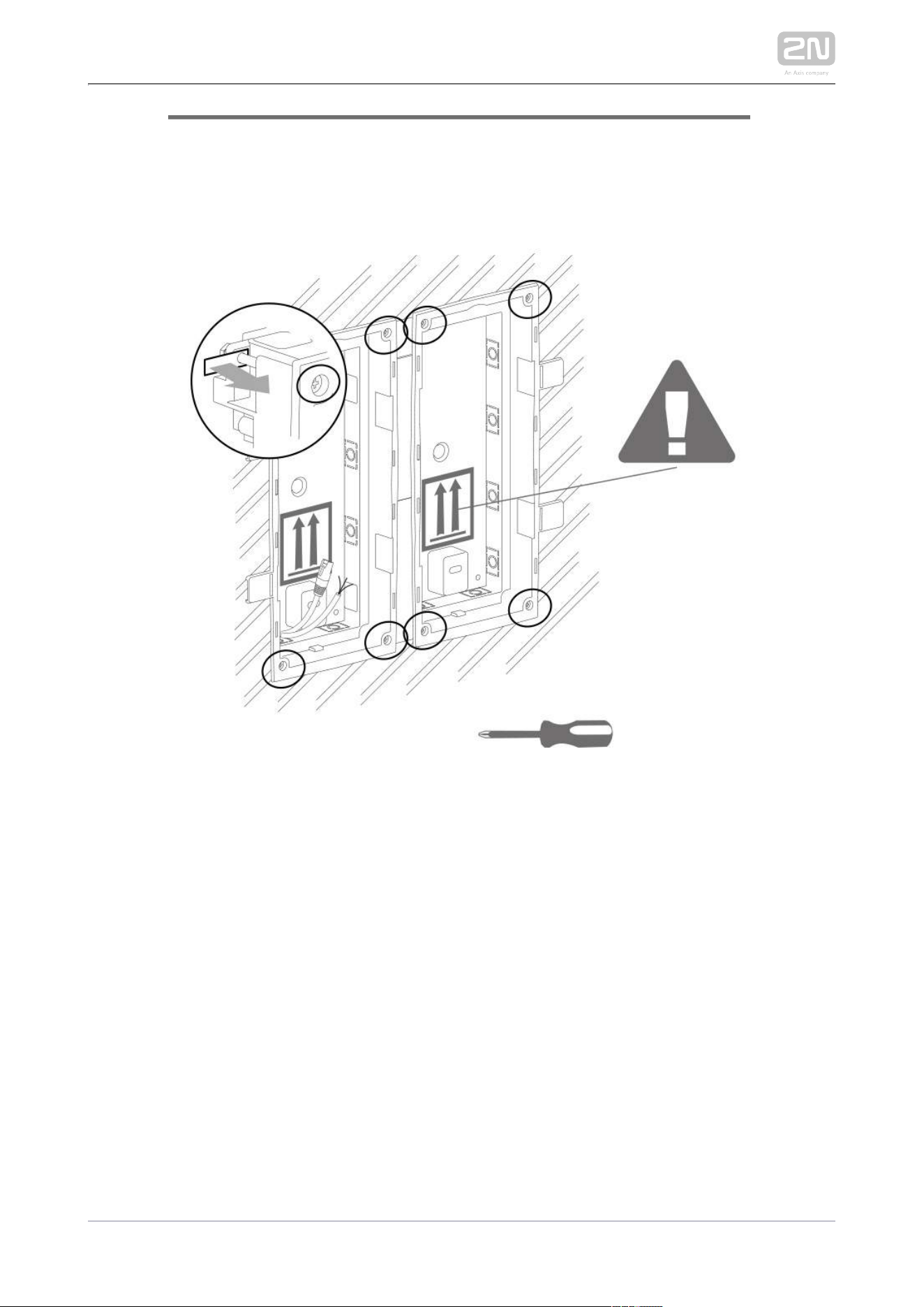
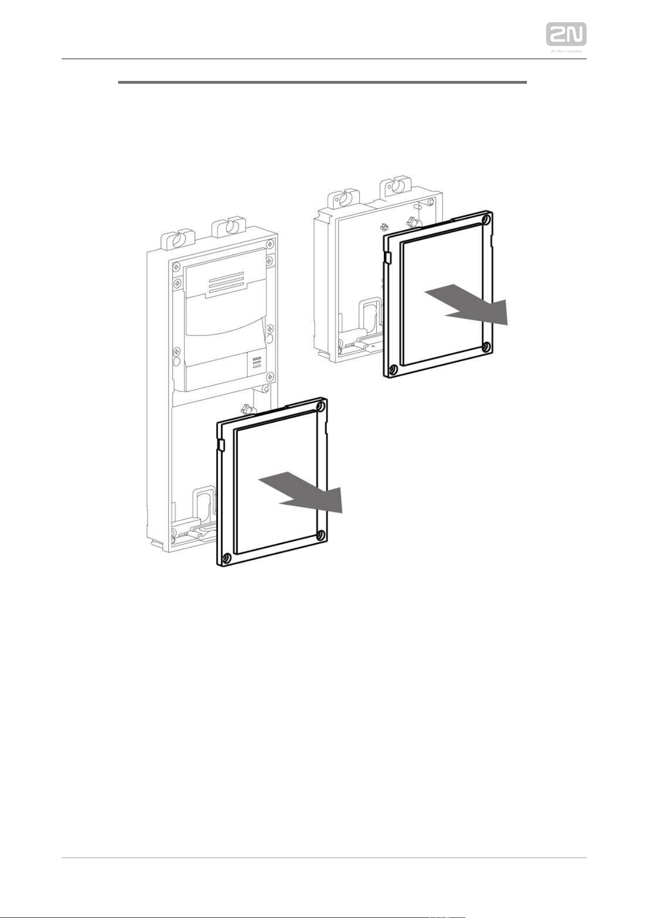
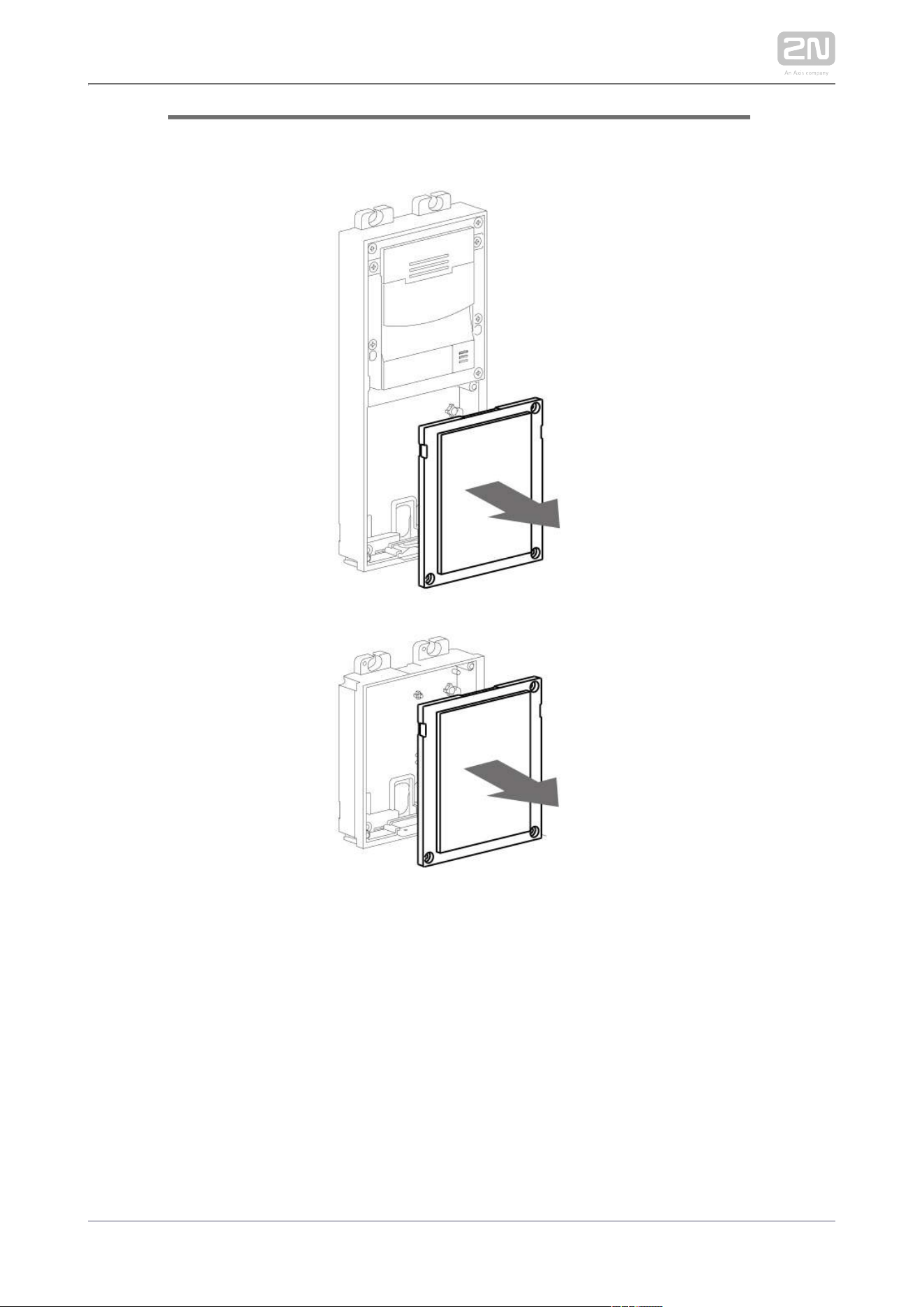
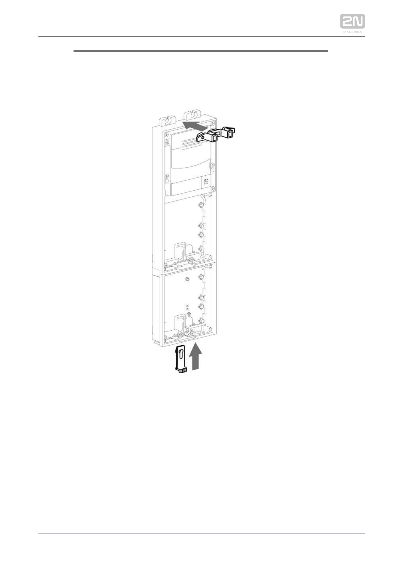
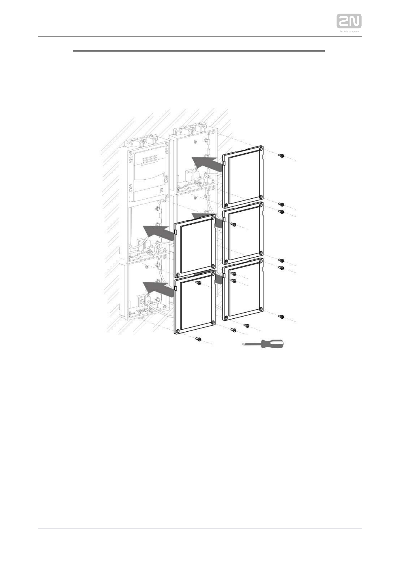
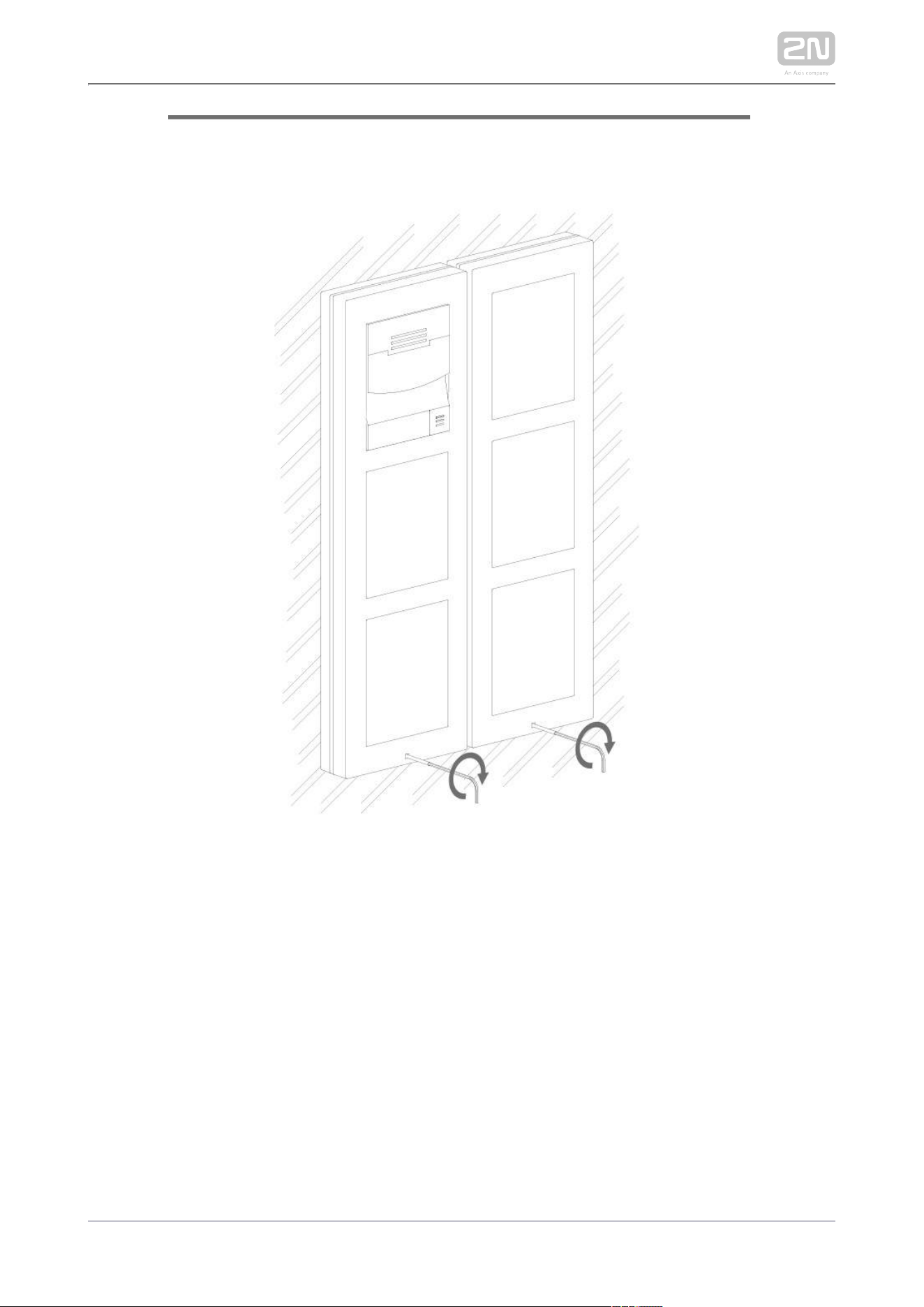
Unscrew the second module cover on the main unit base.
Use a flat screwdriver to take out the module cover.
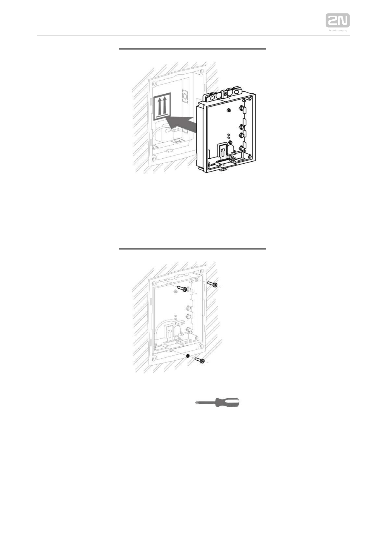
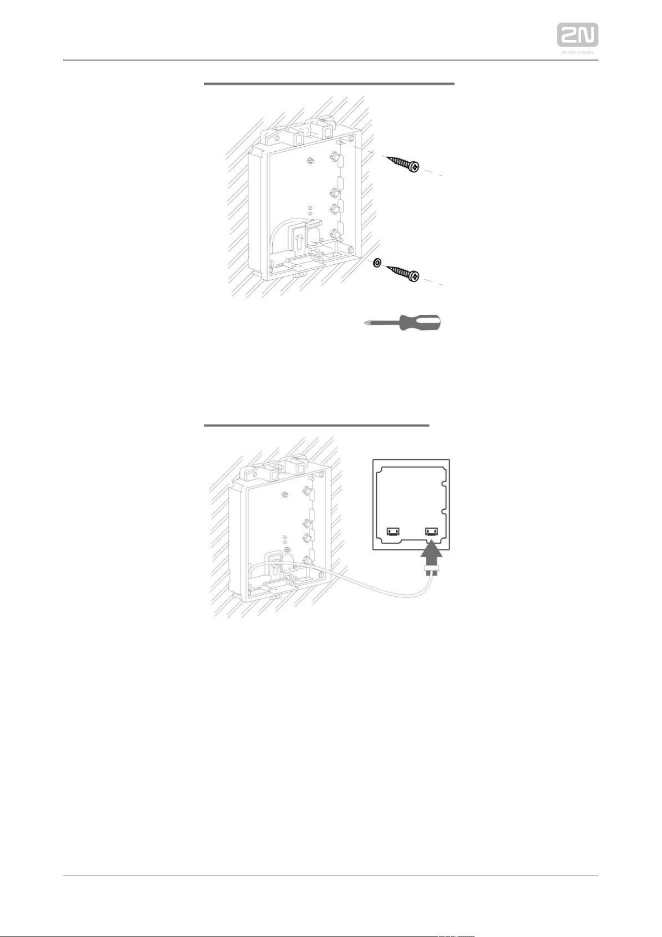
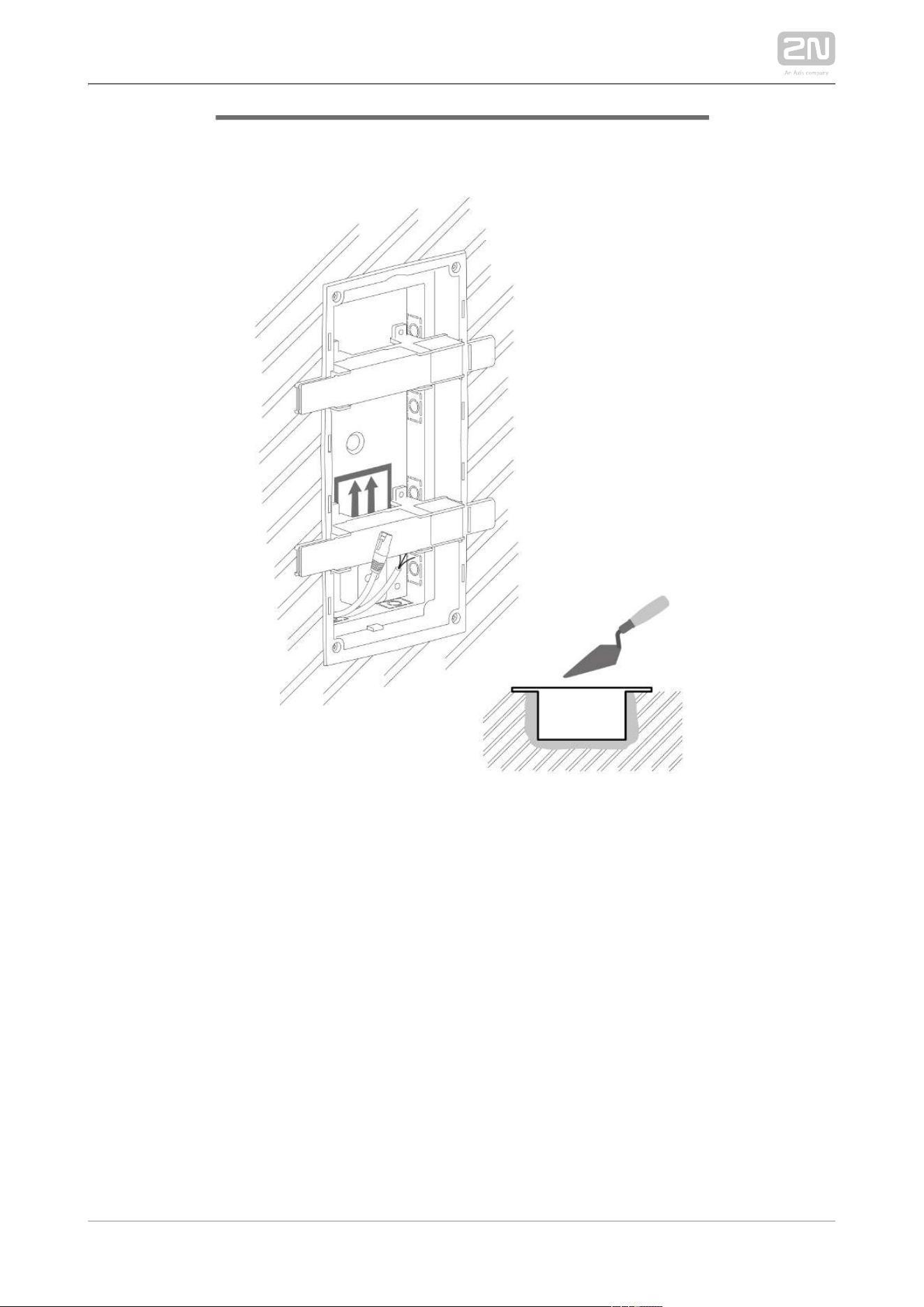
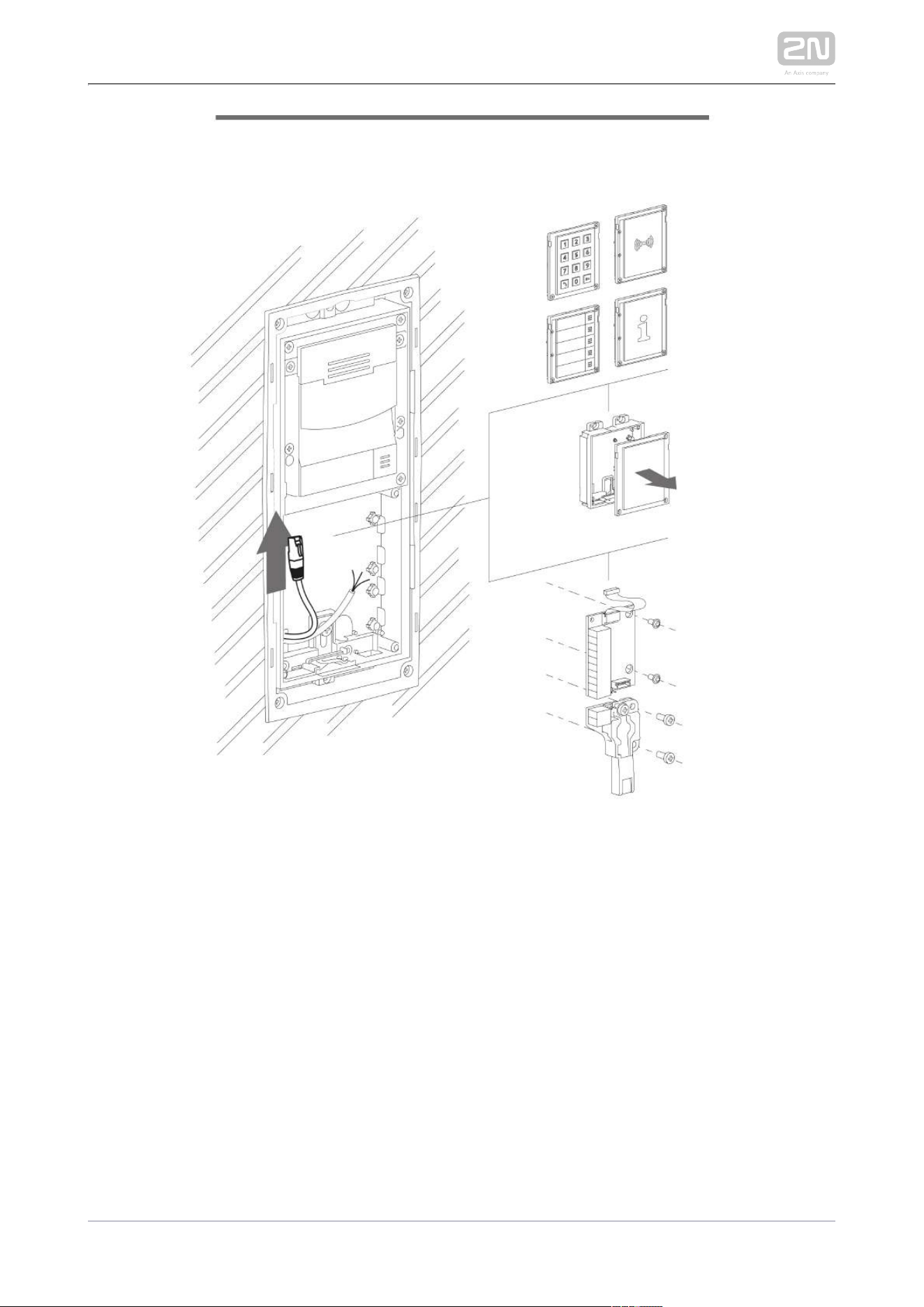
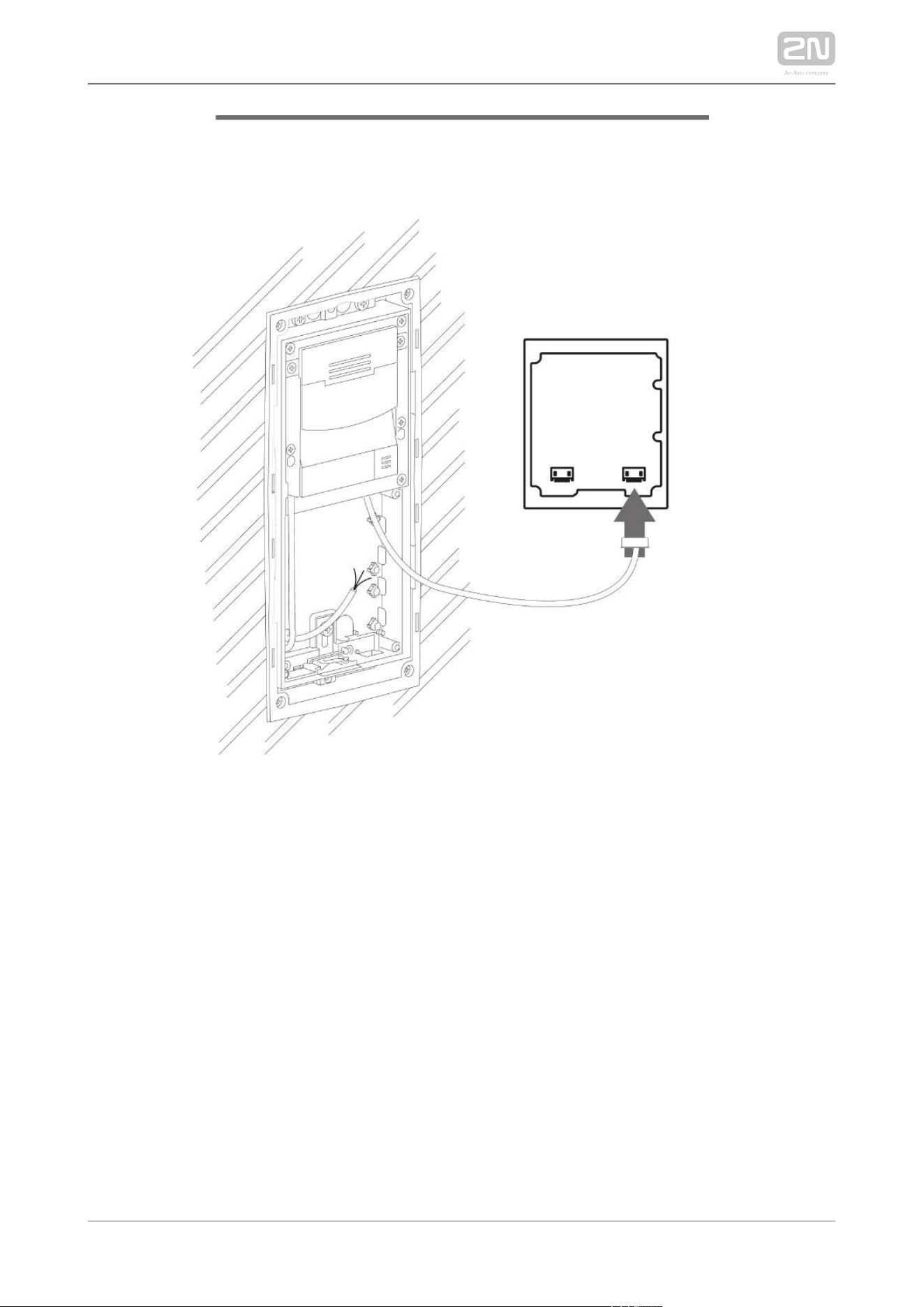
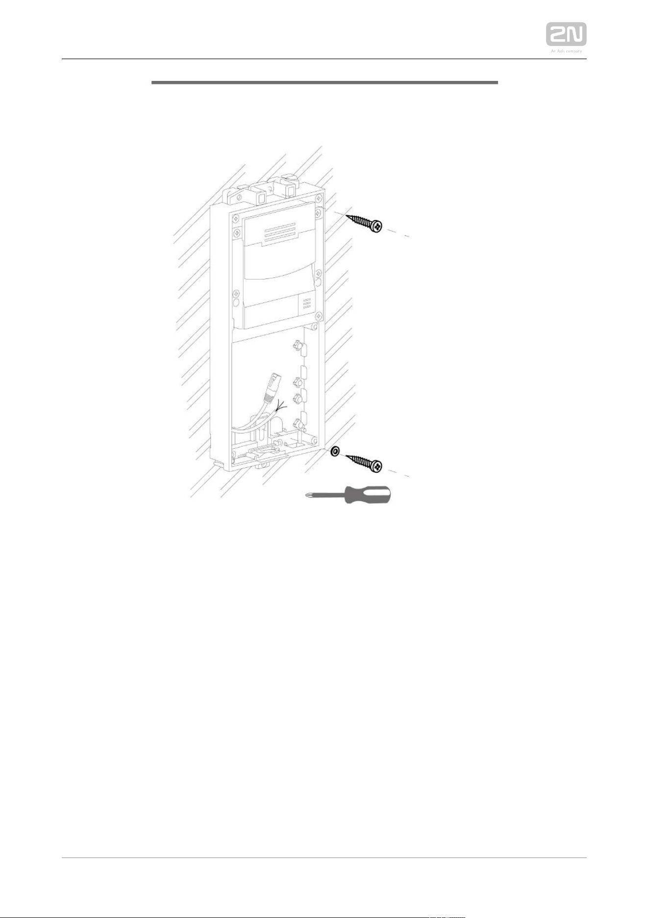
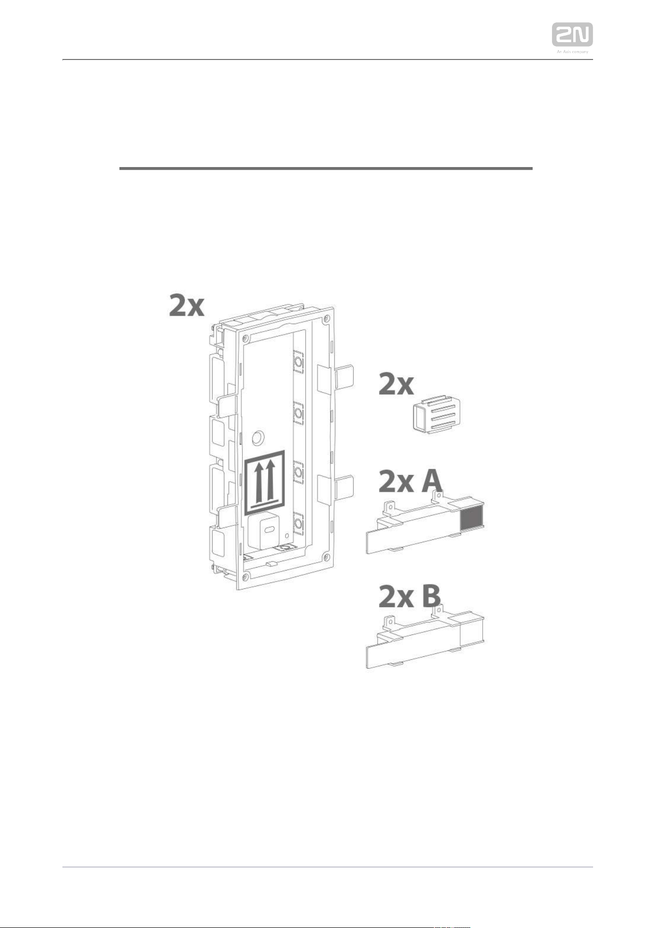
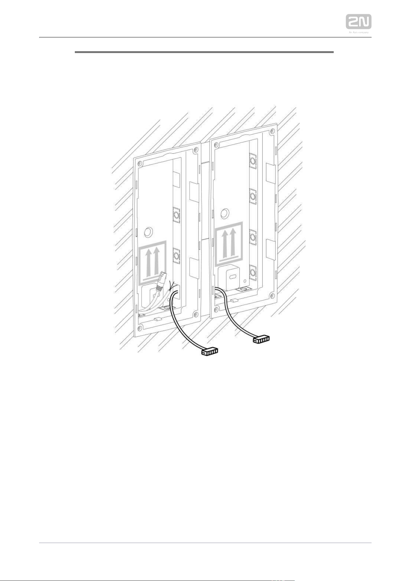
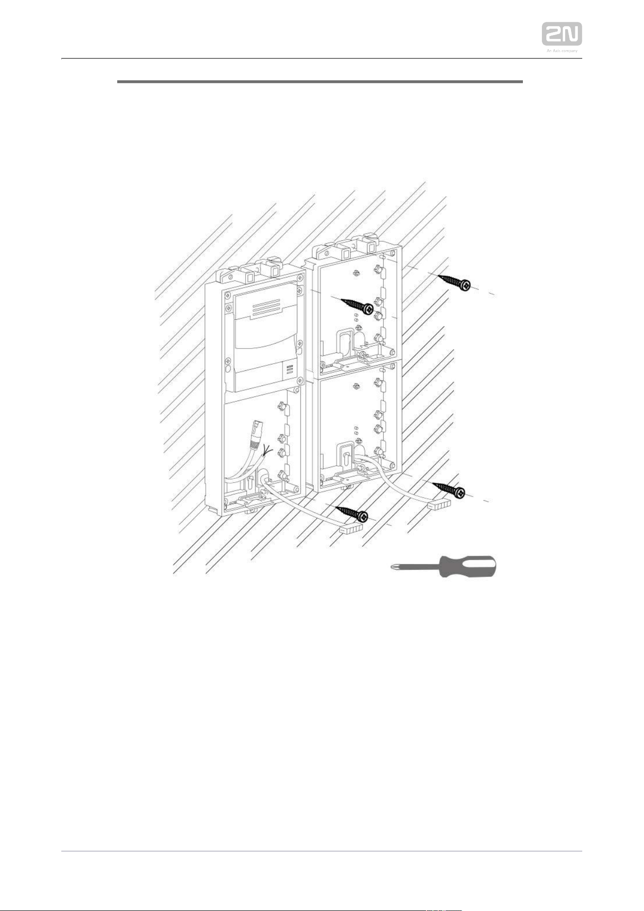
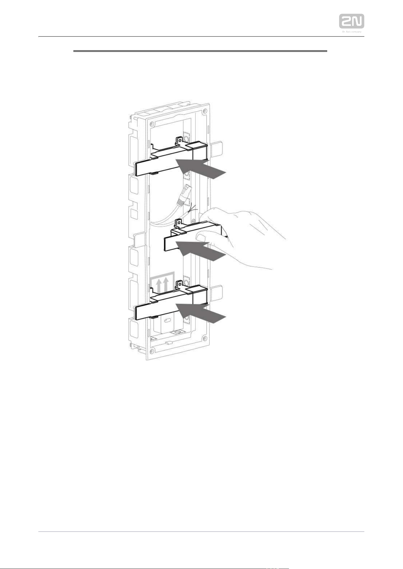
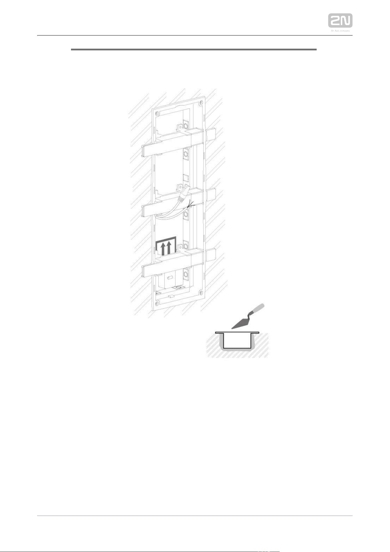
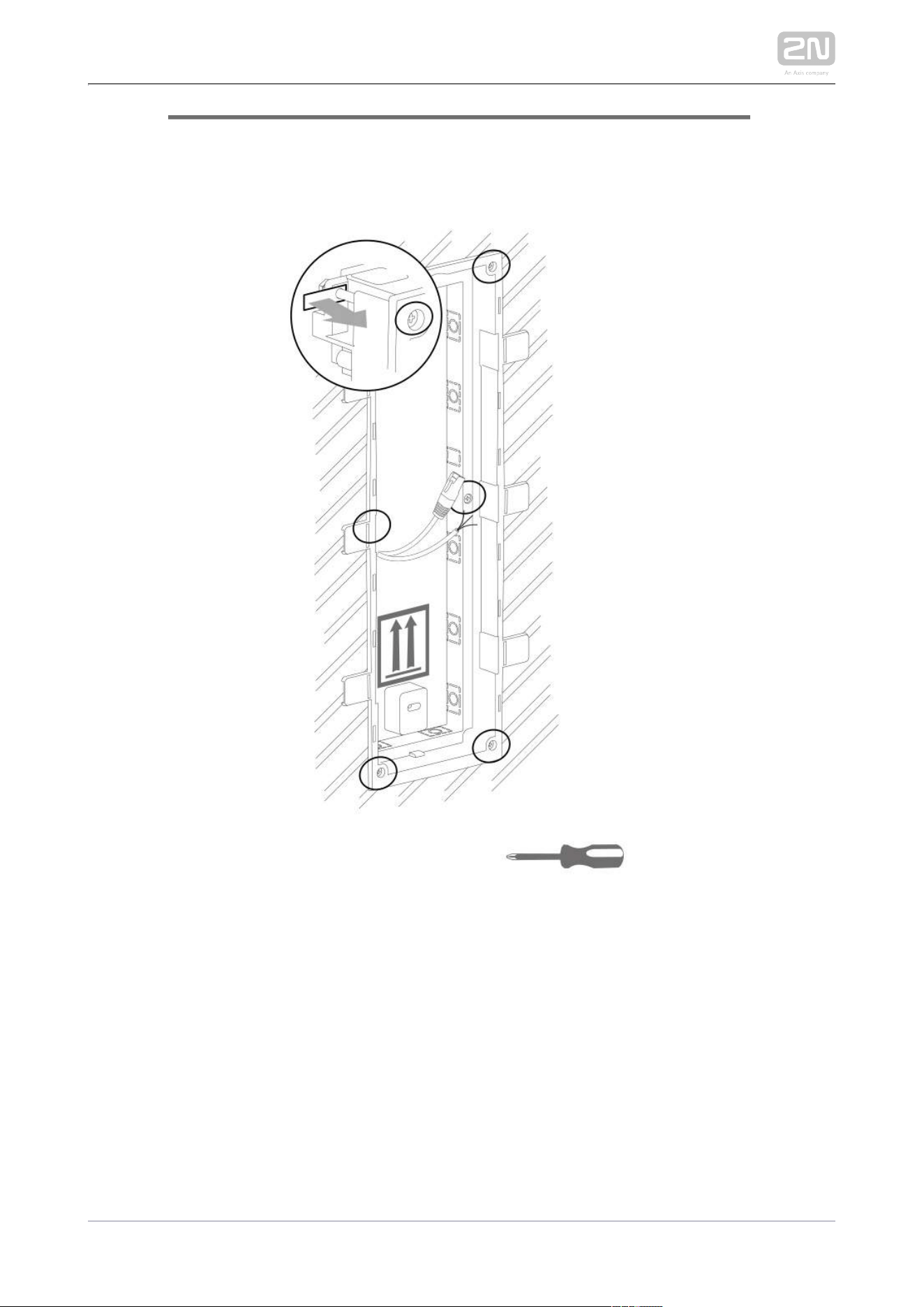
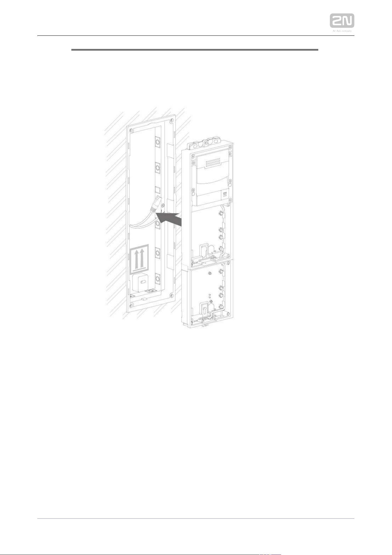
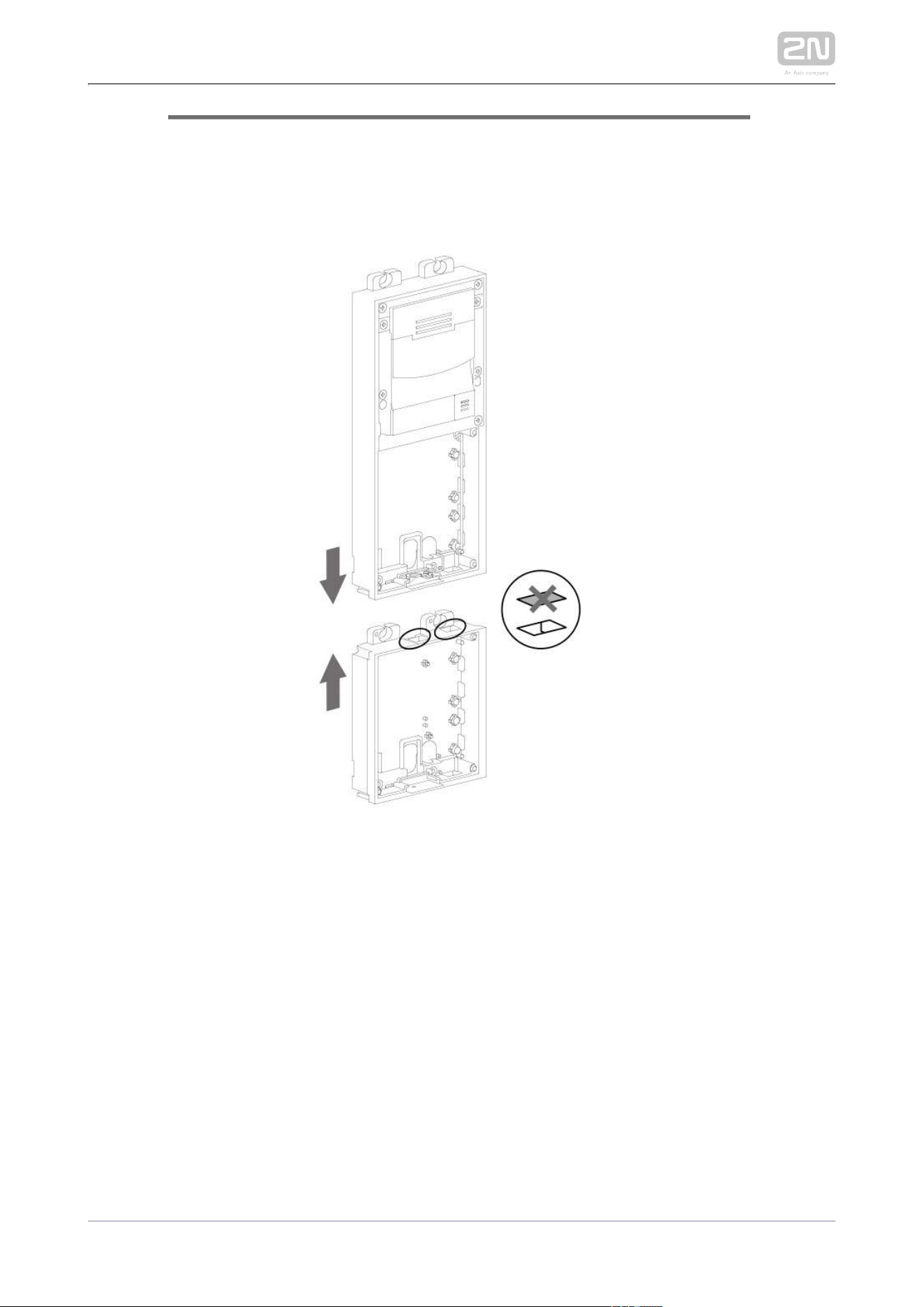
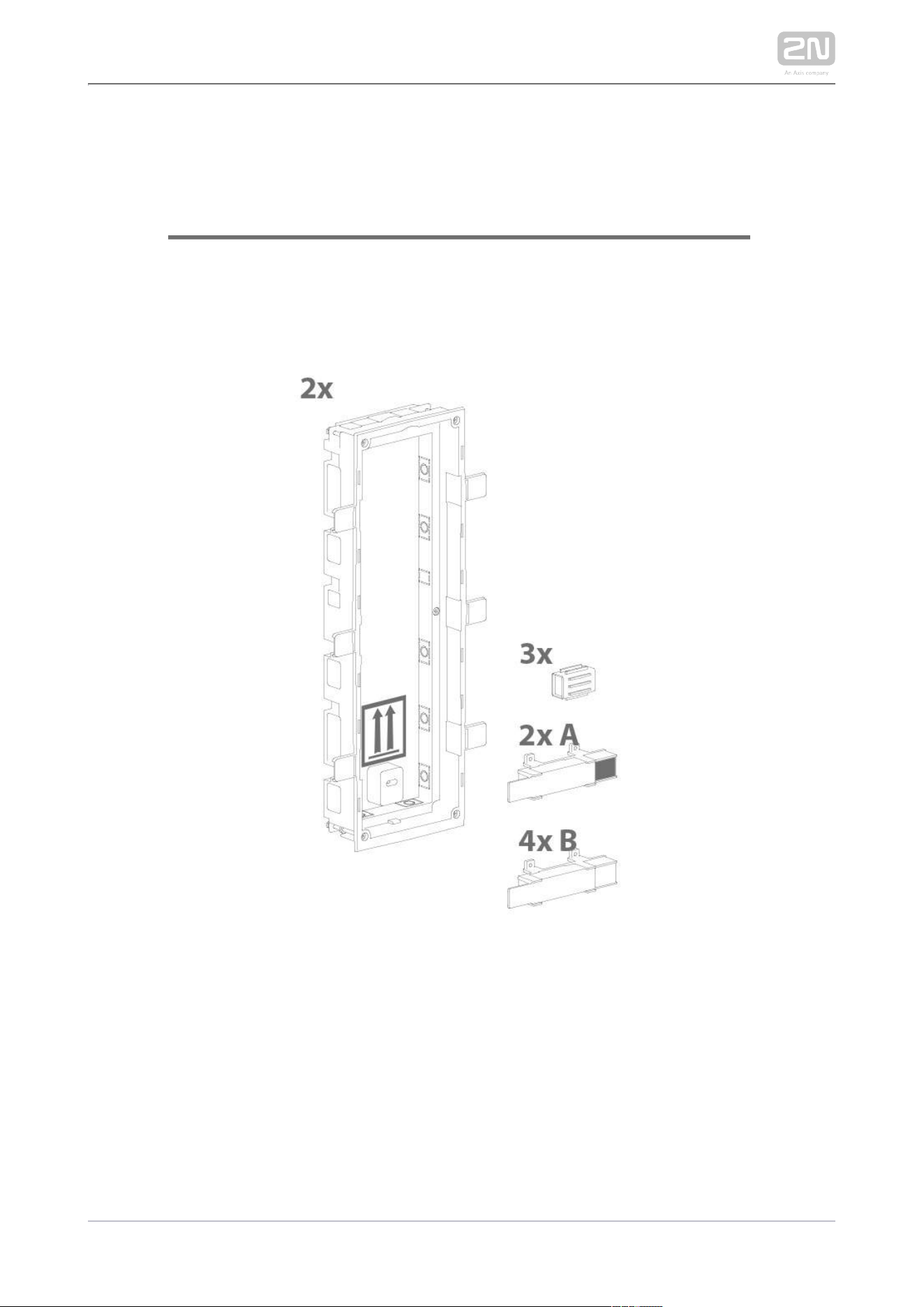
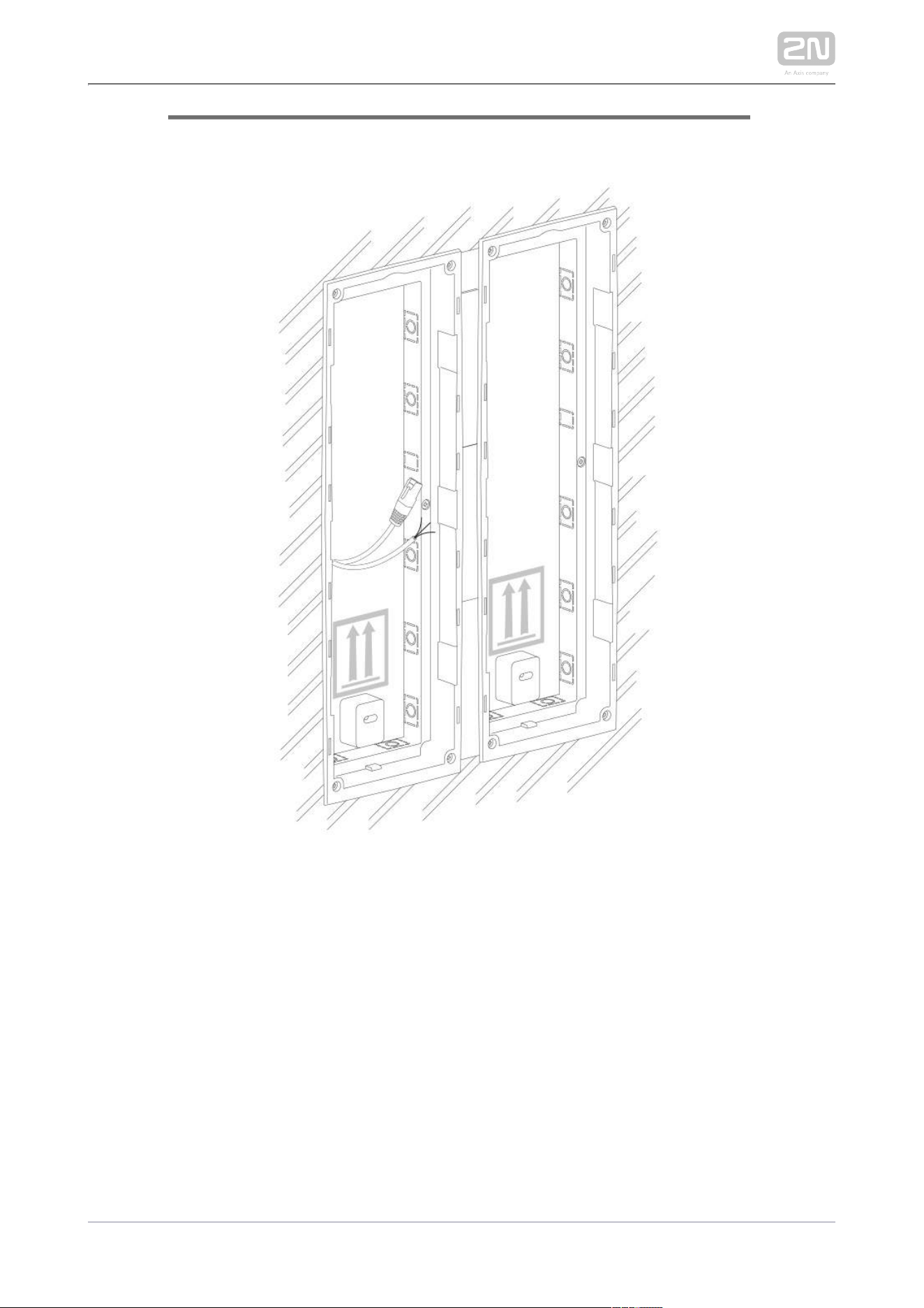
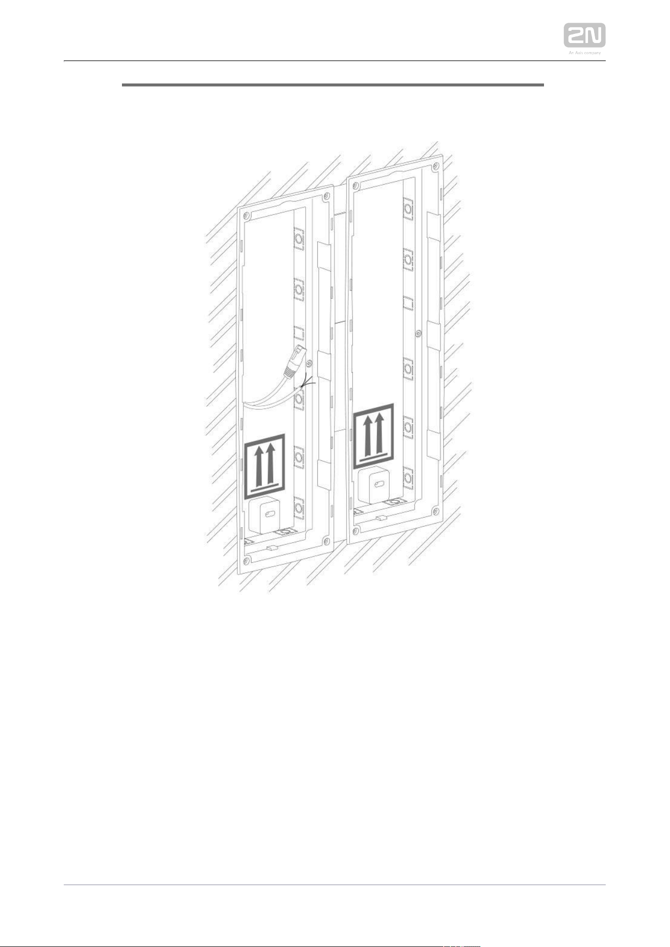
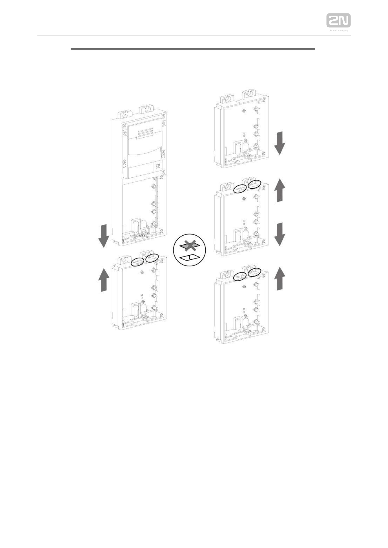
Version A – 2-Module Base
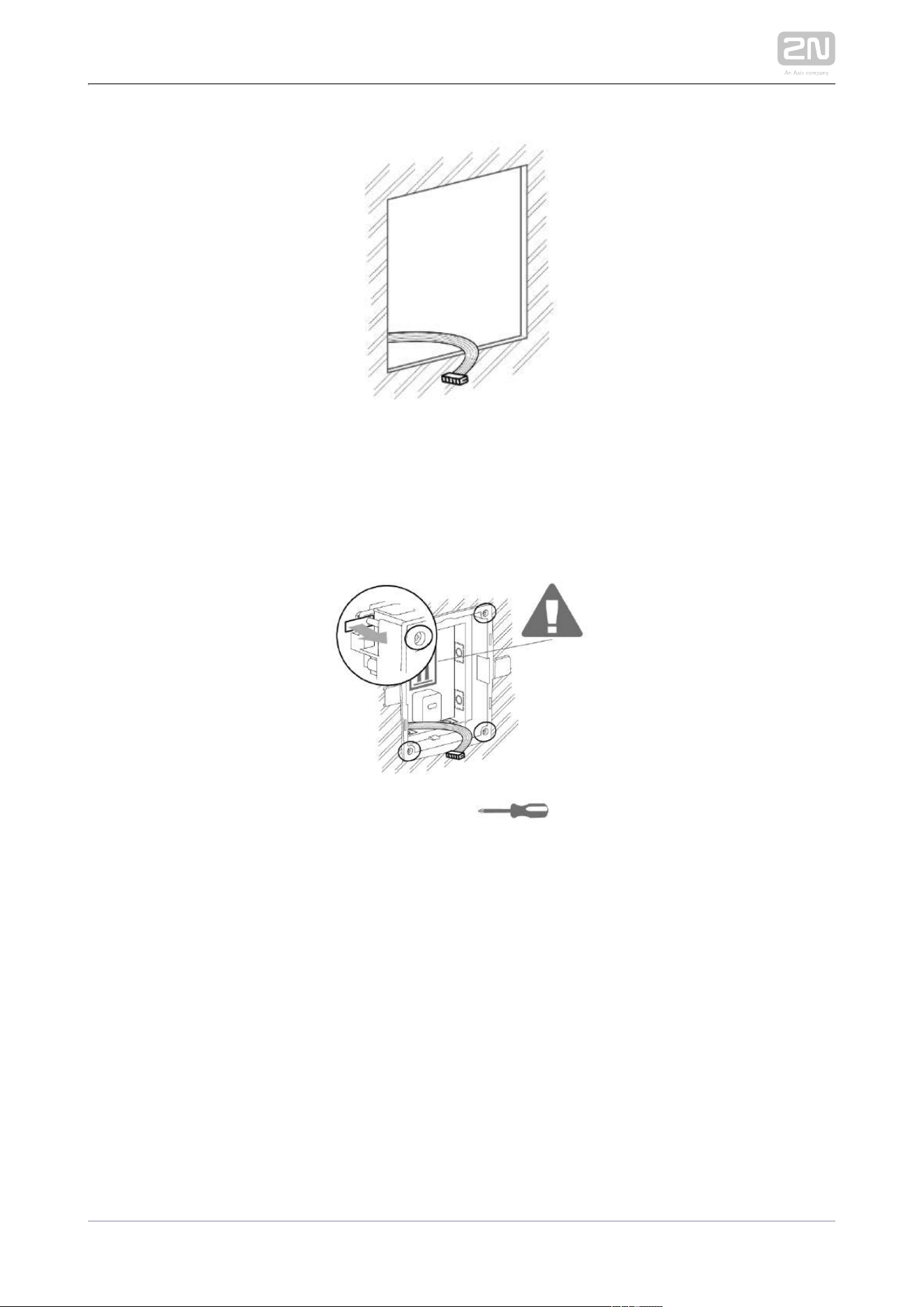
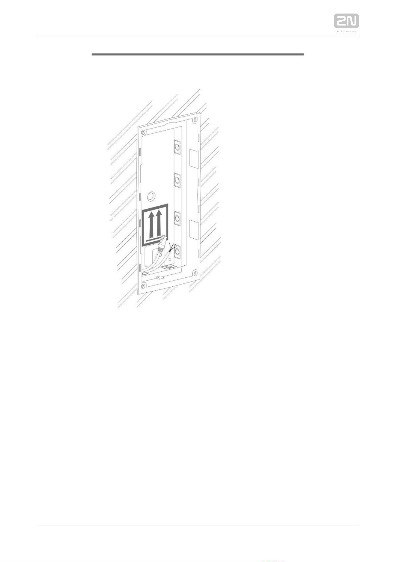
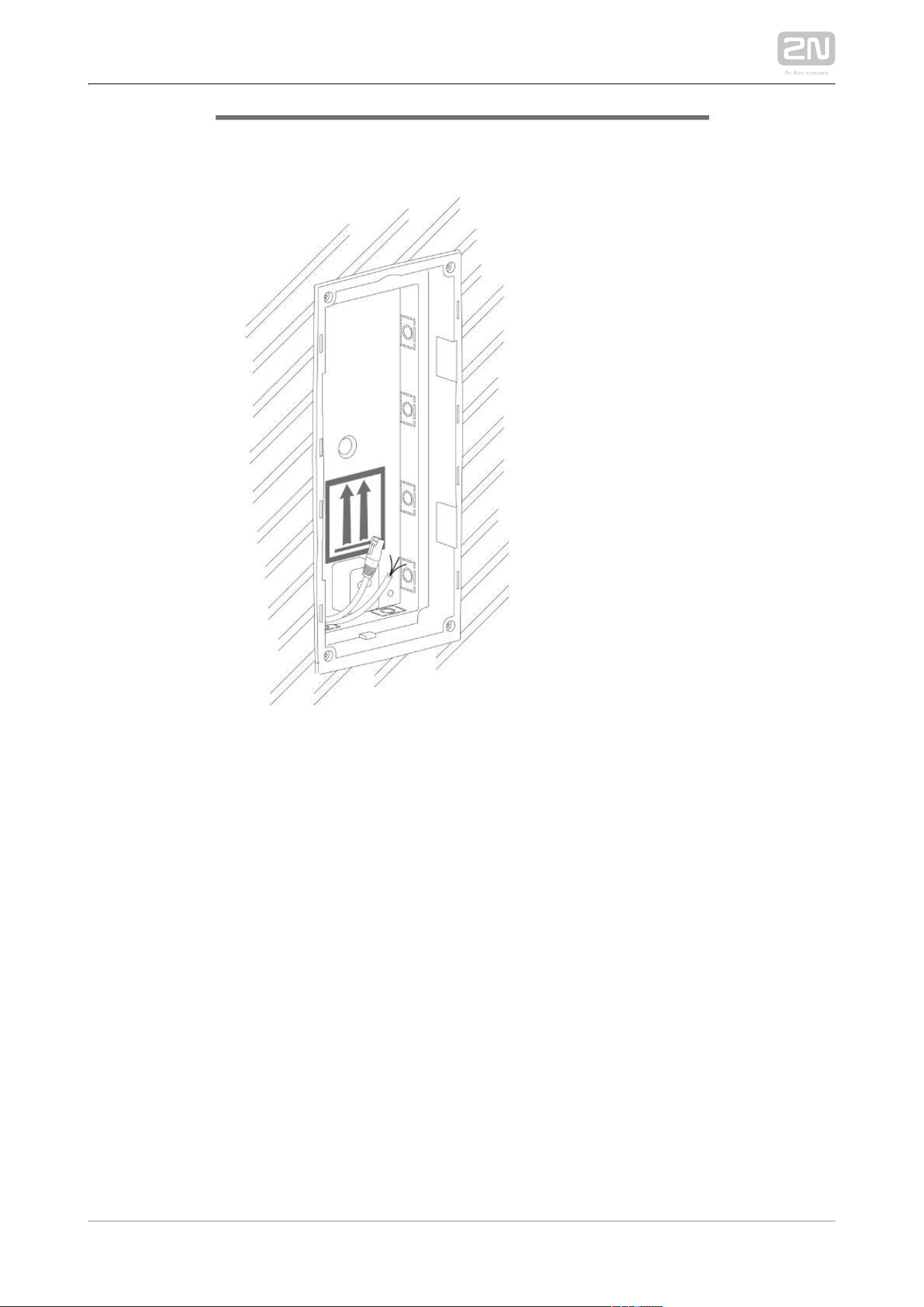
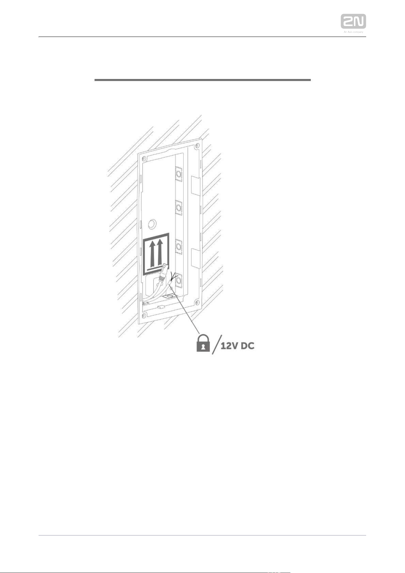
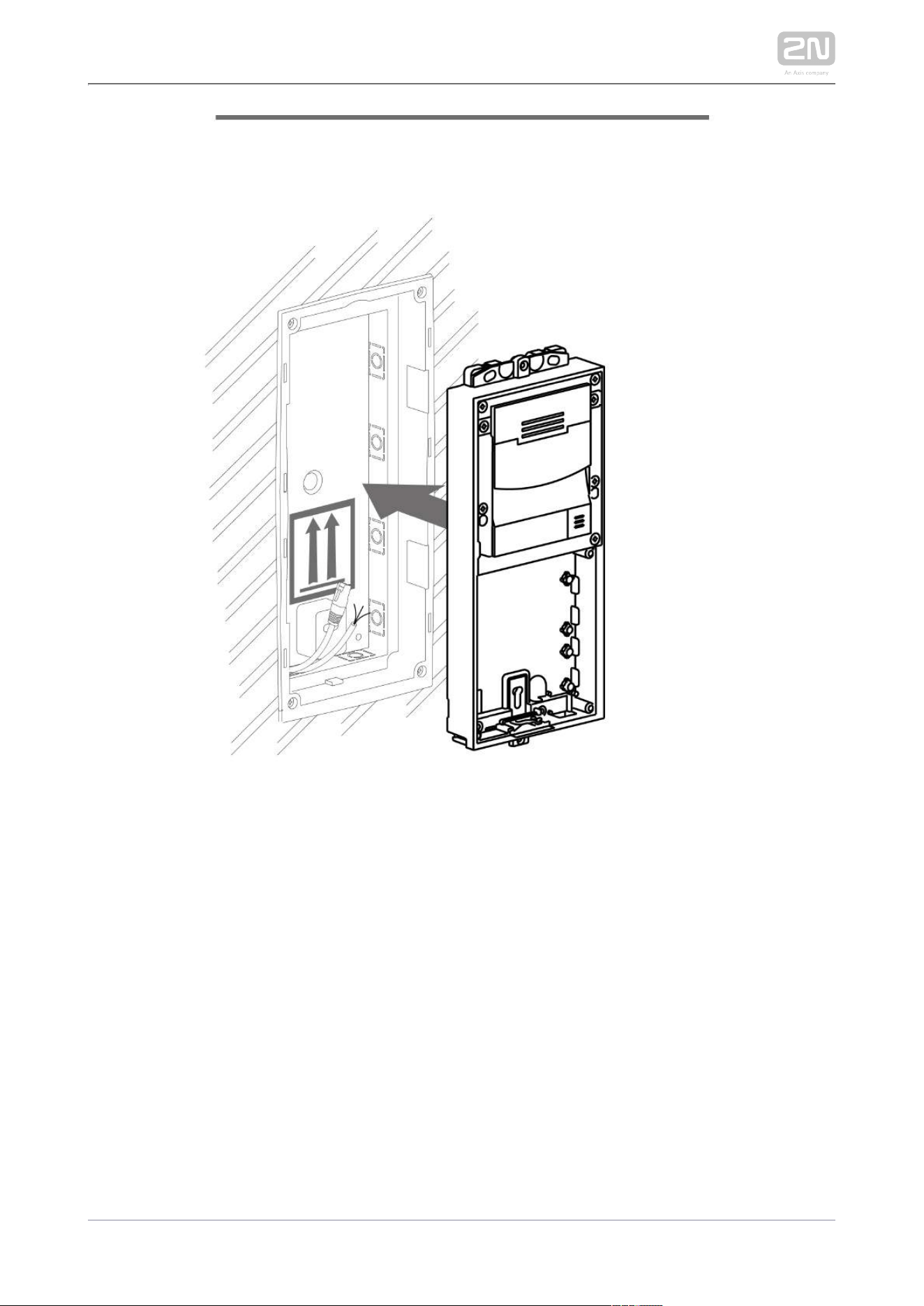
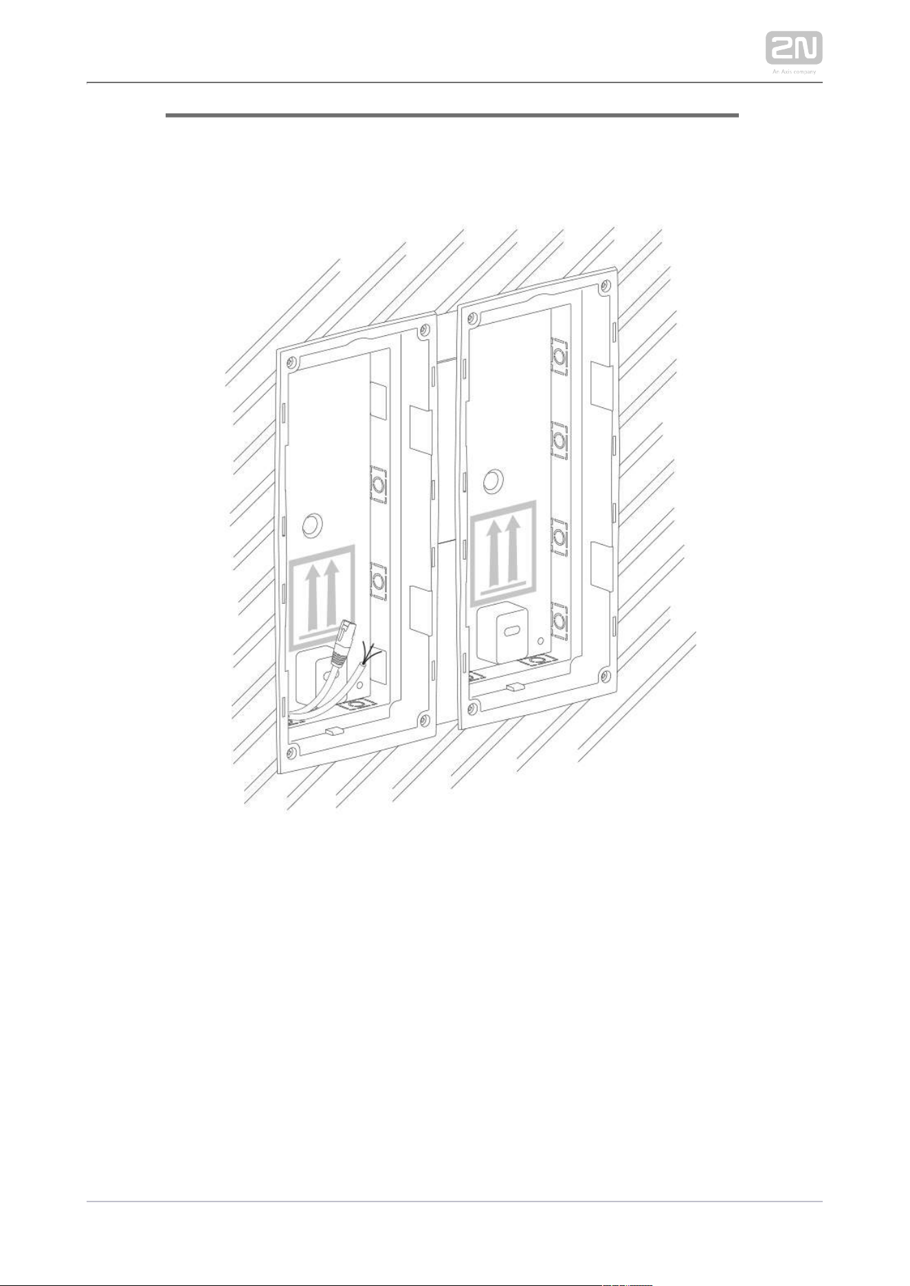
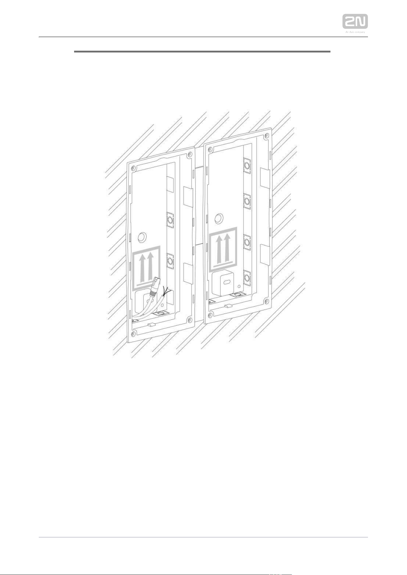
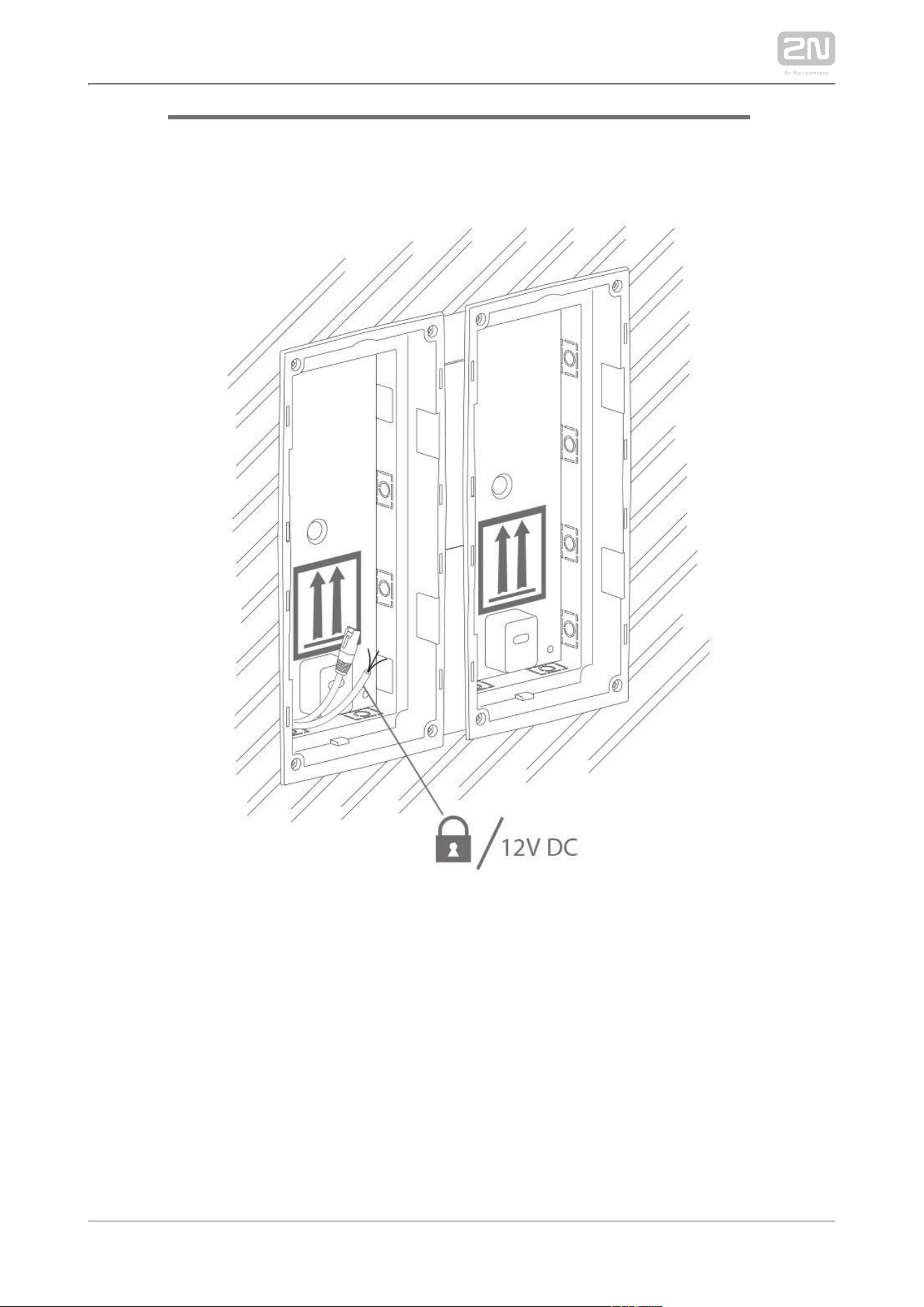
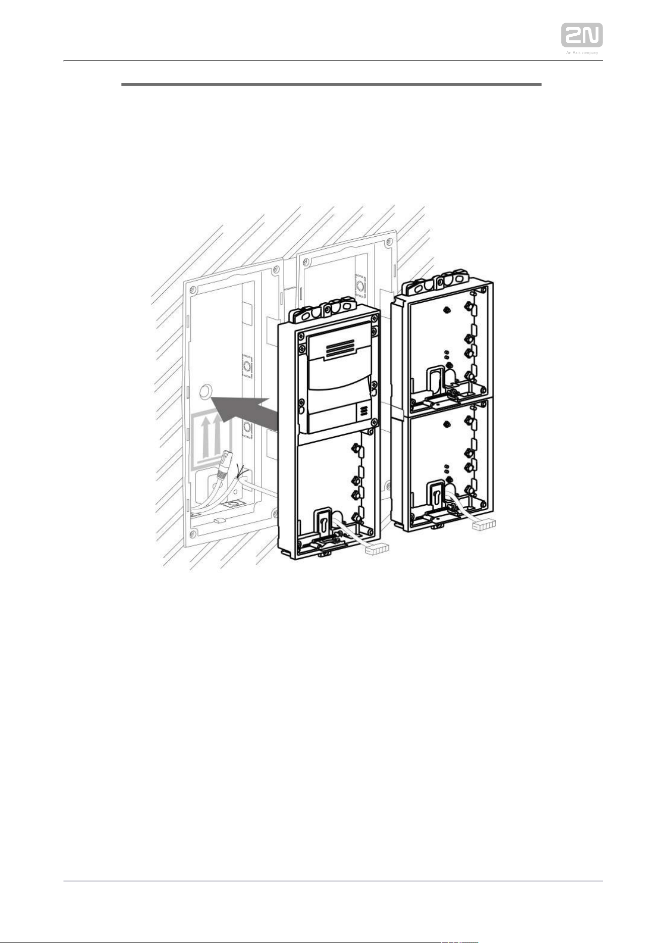
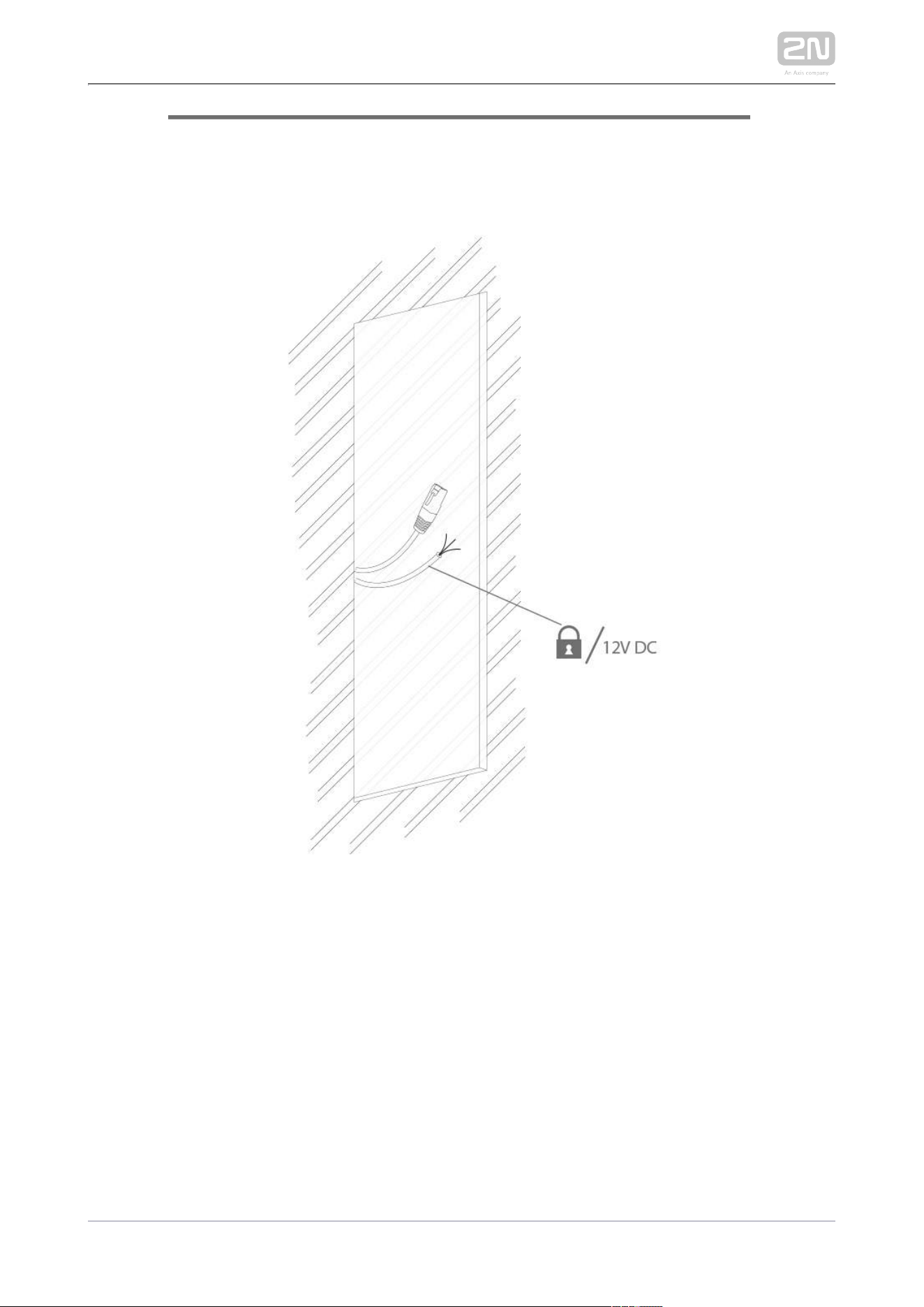
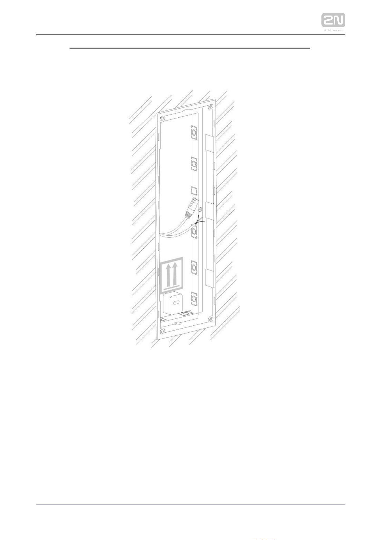
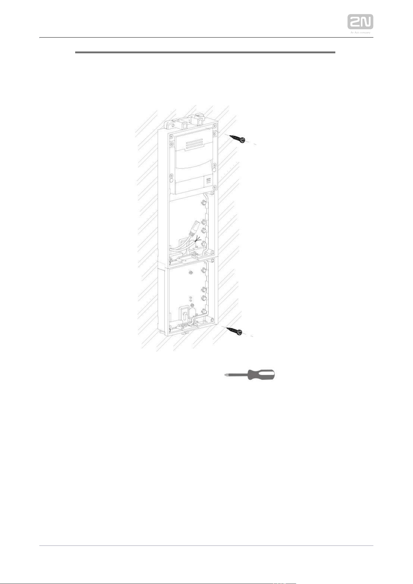
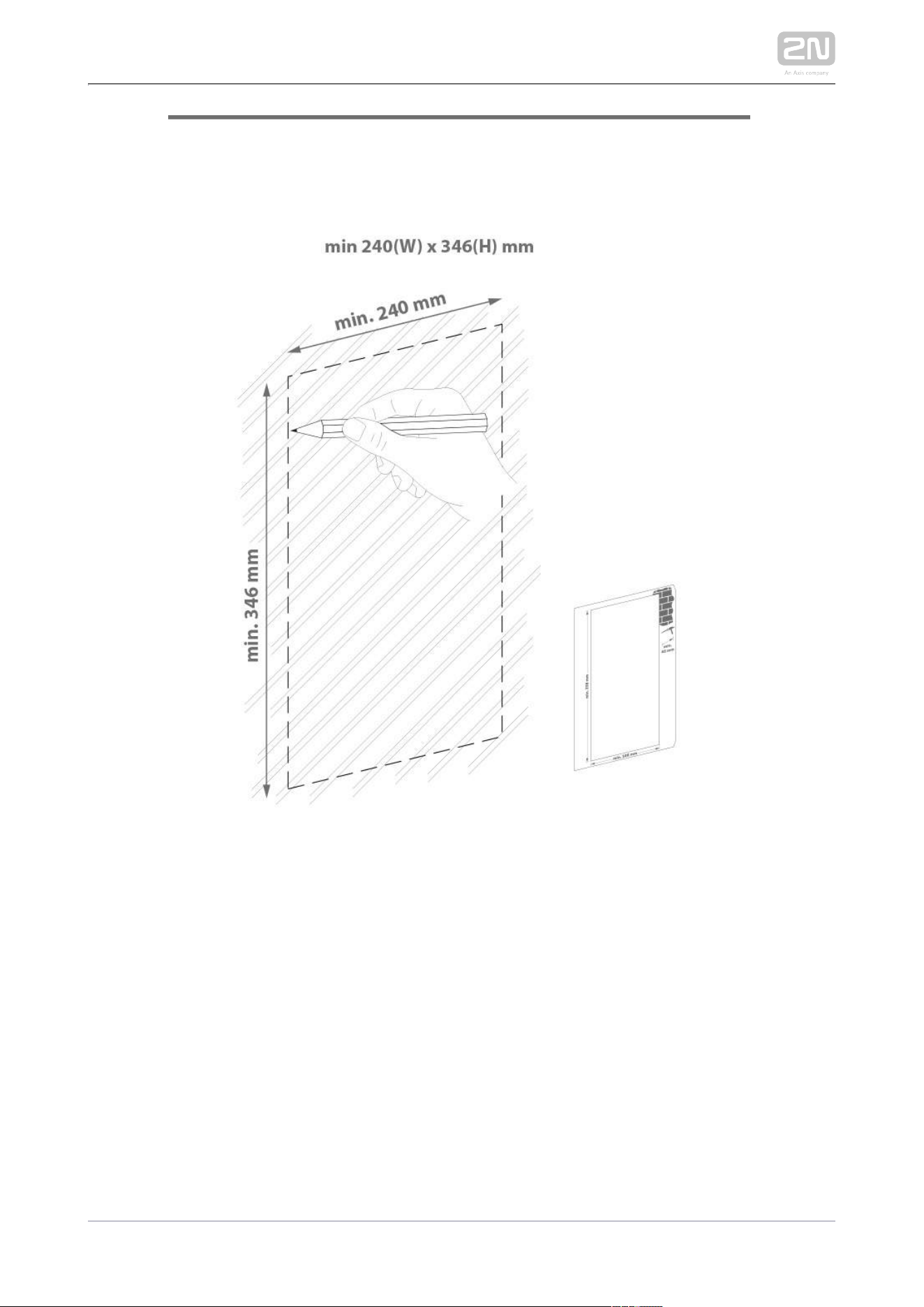
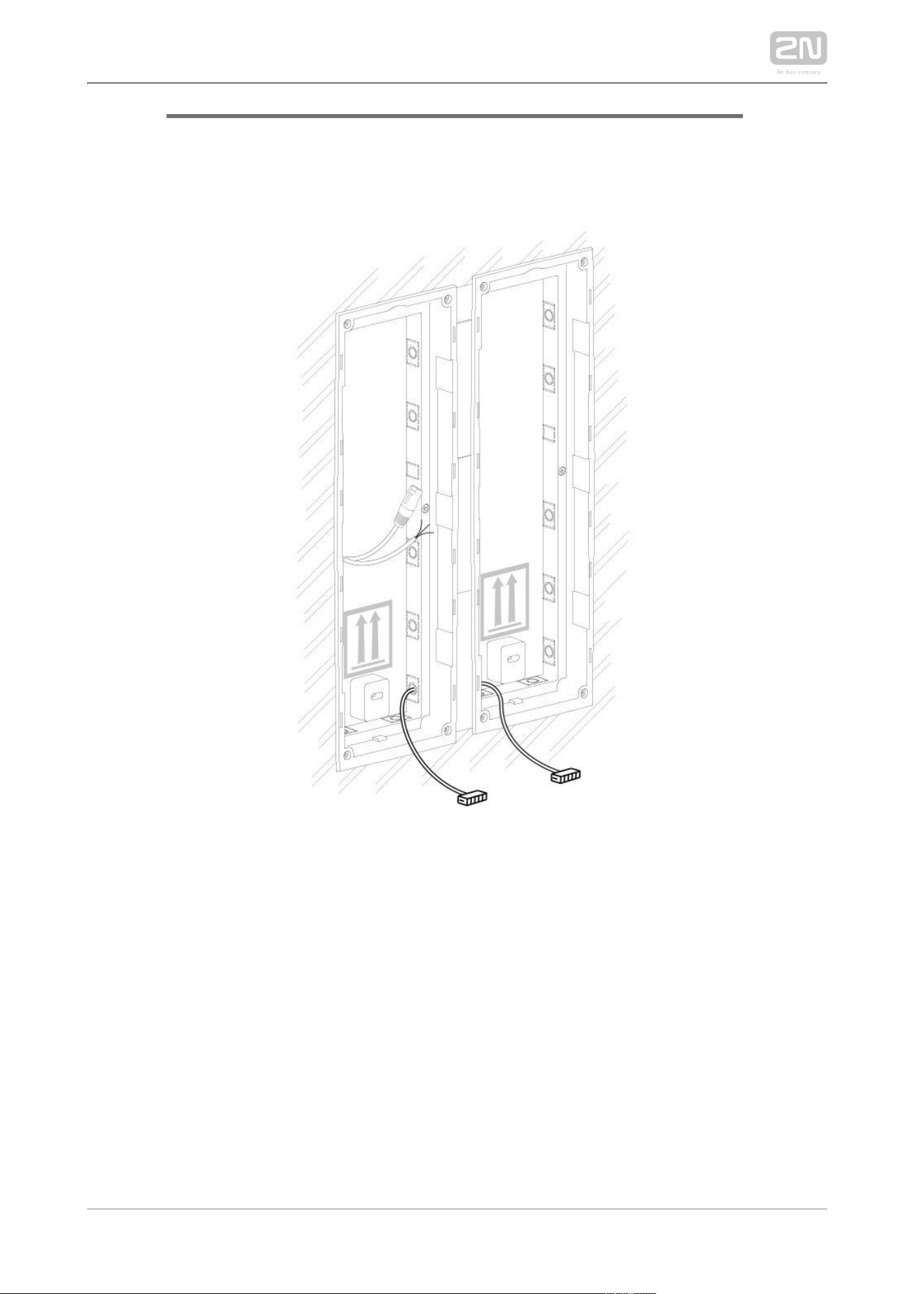
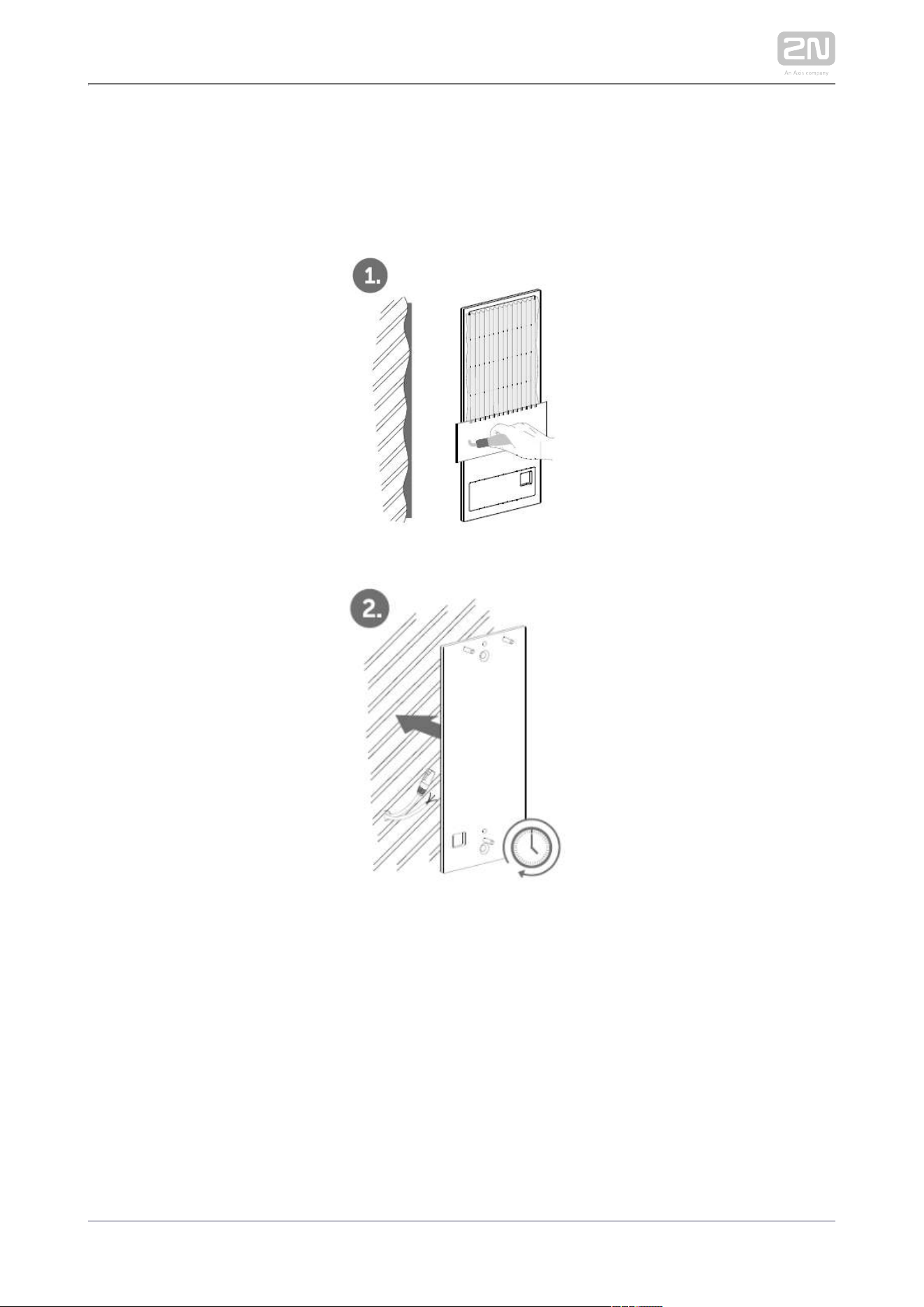
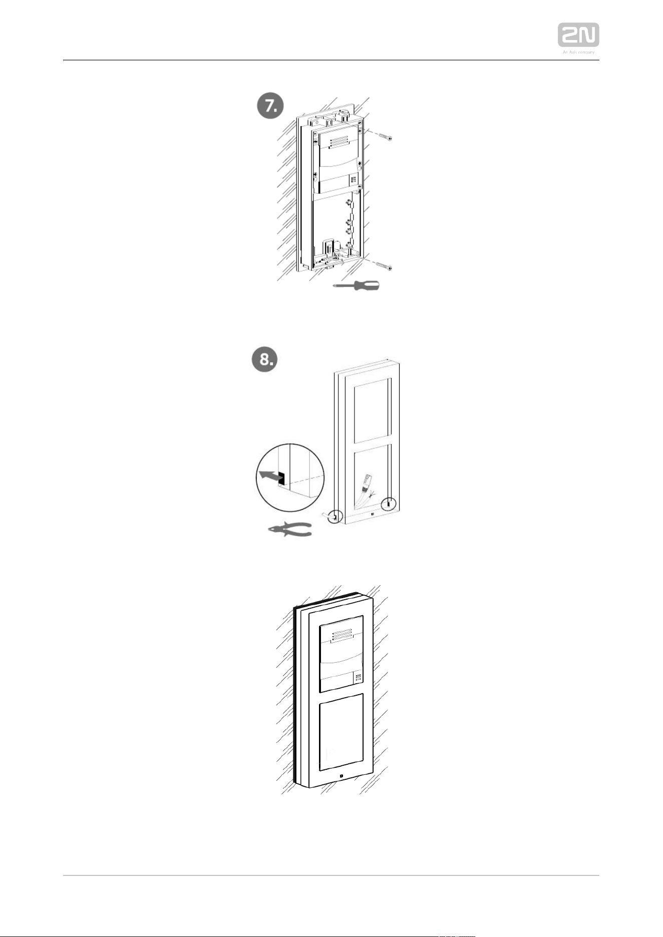
Place the base on the flush mounting box / predrilled holes with dowels and pull
the cables through the bottom holes. Pull the Ethernet cable including the
connector through the bottom hole to the left if necessary.
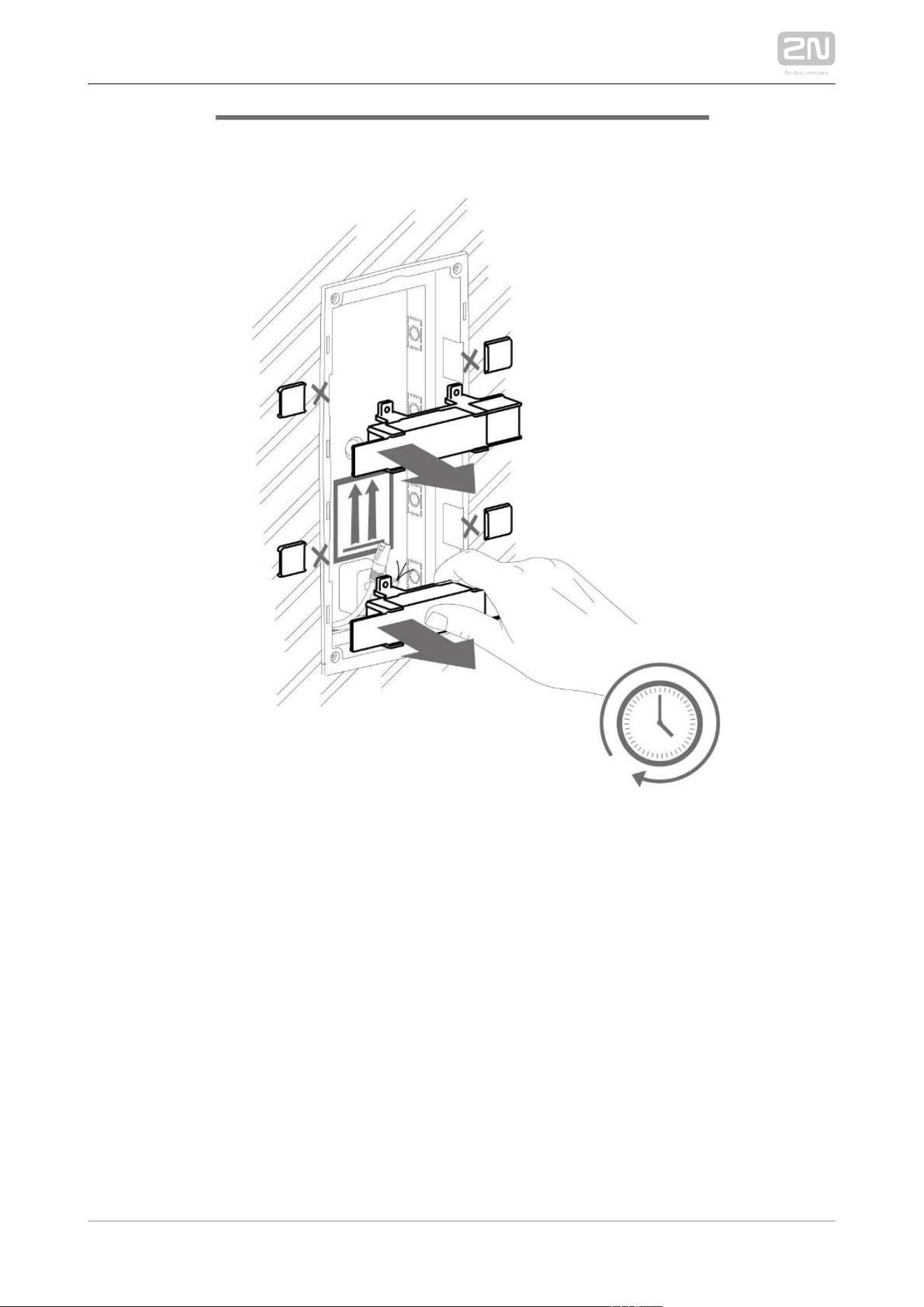
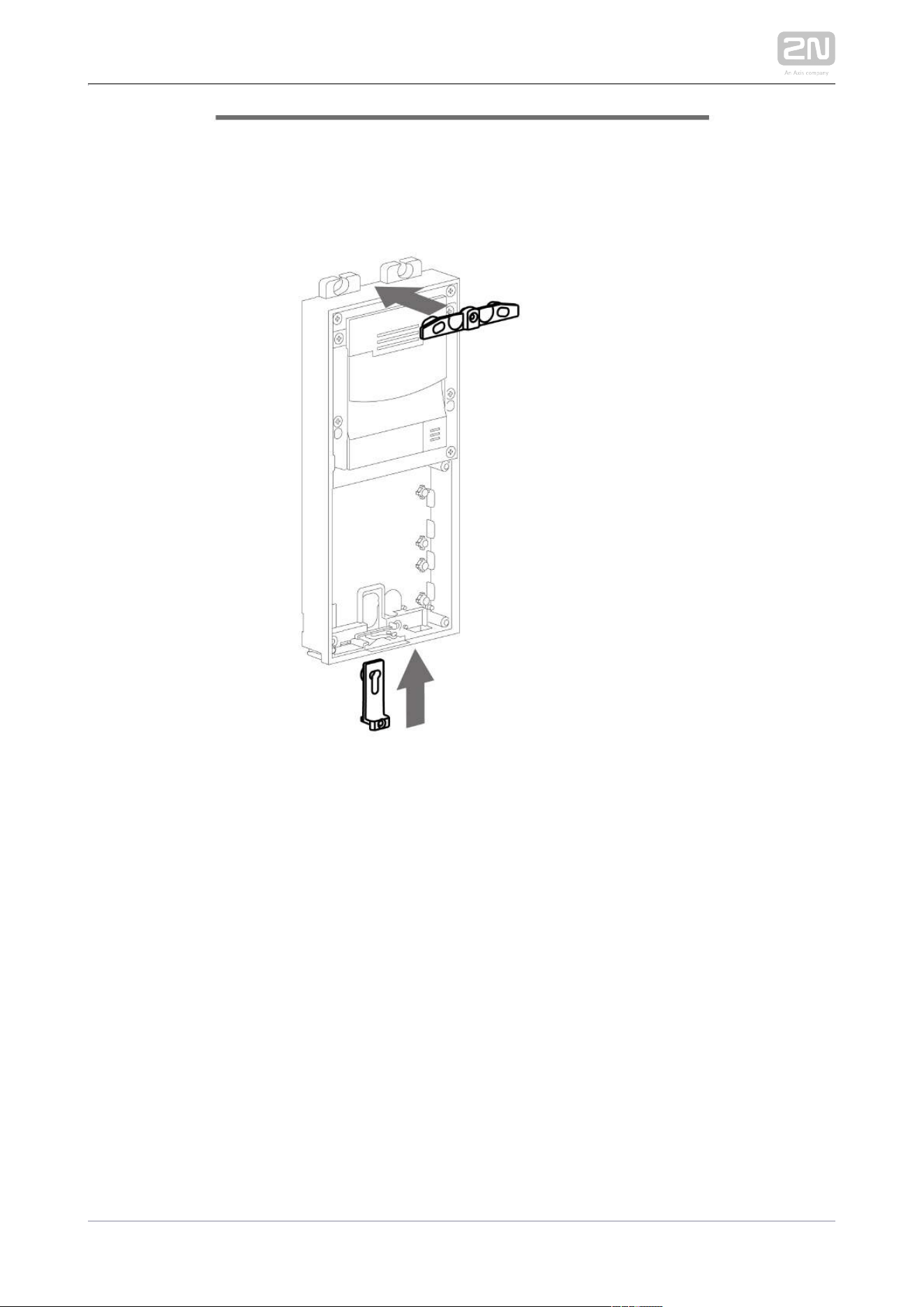
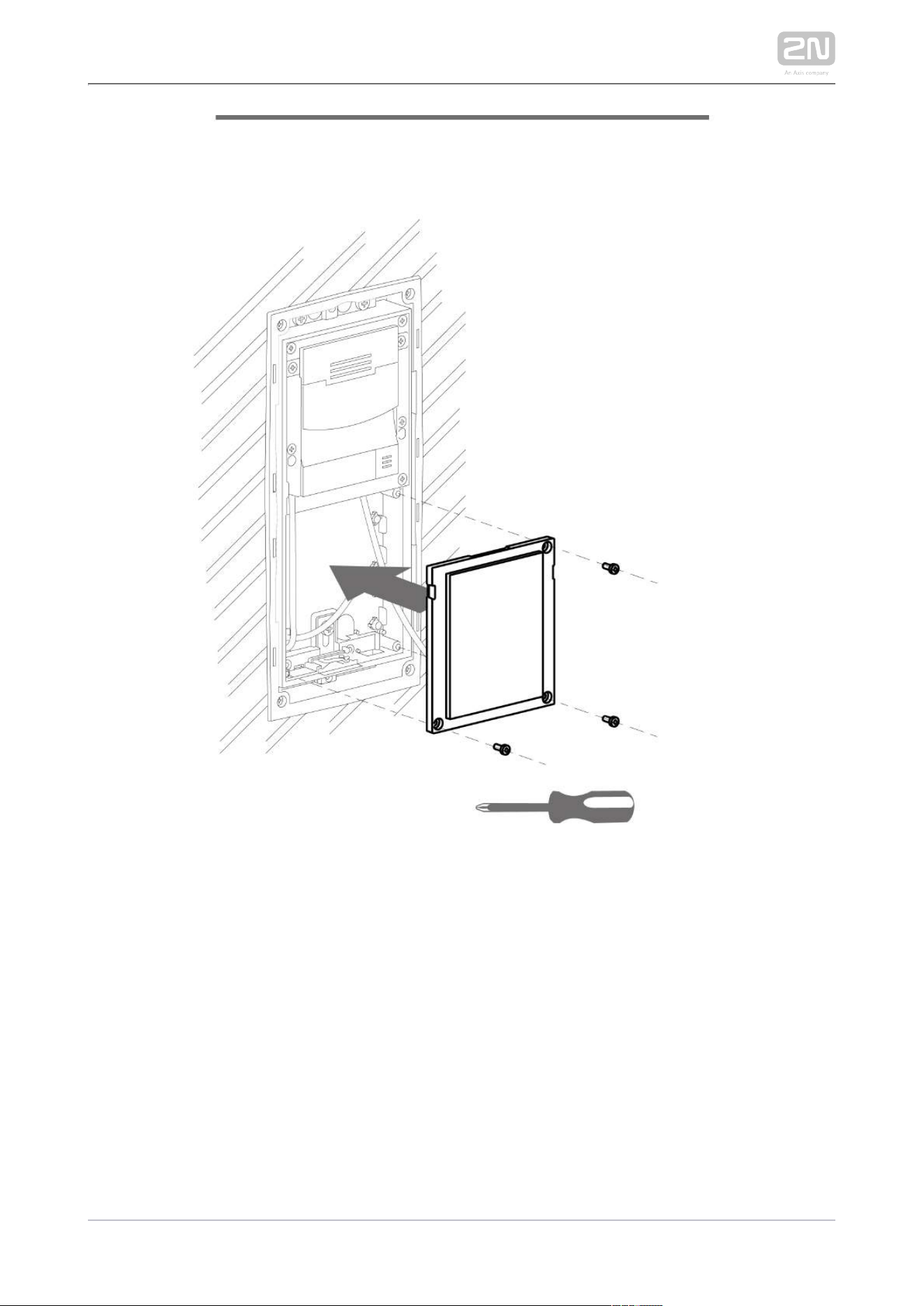
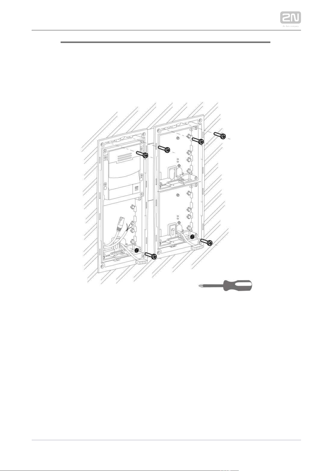
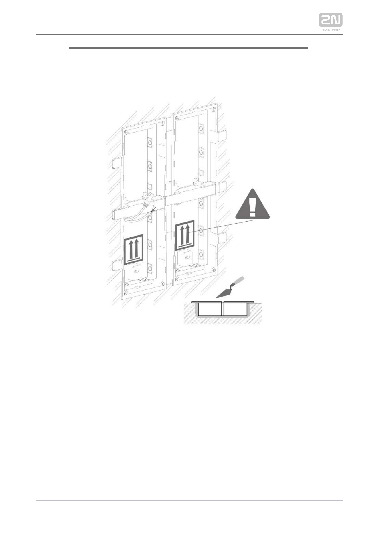
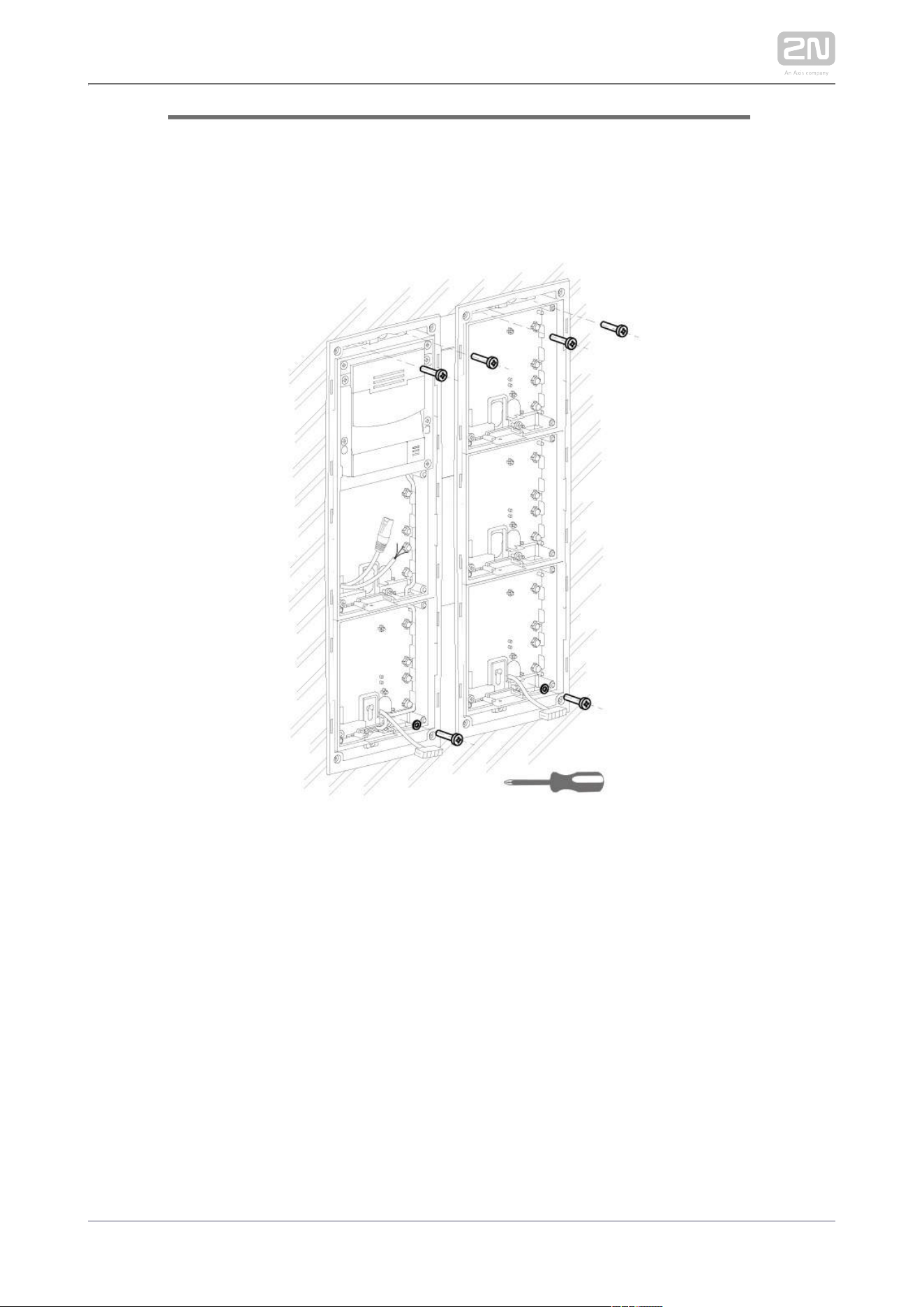
Insert the metal fitting elements up and down and screw the base plate tight.
You can level the base slightly if you are mounting just one base.
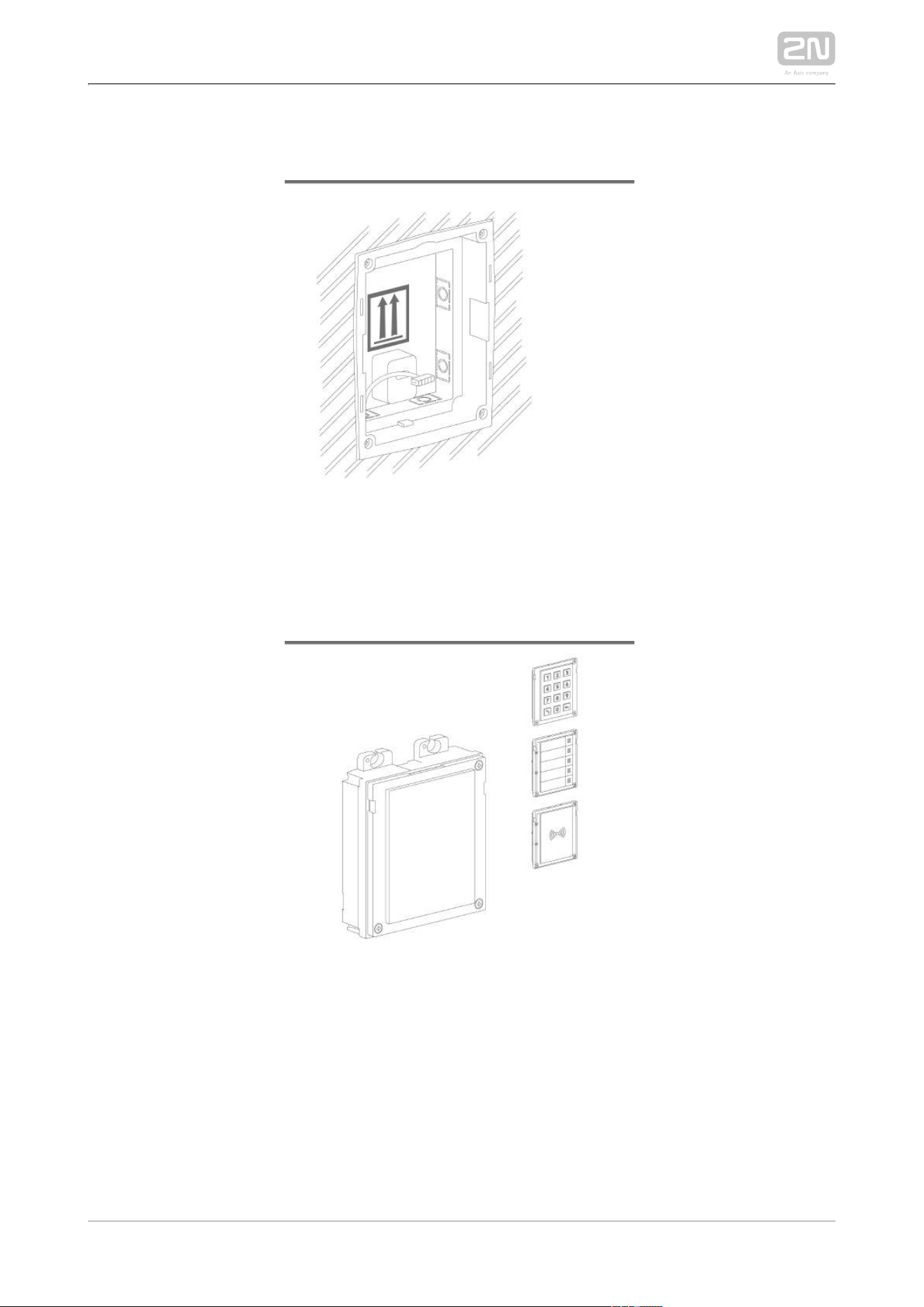
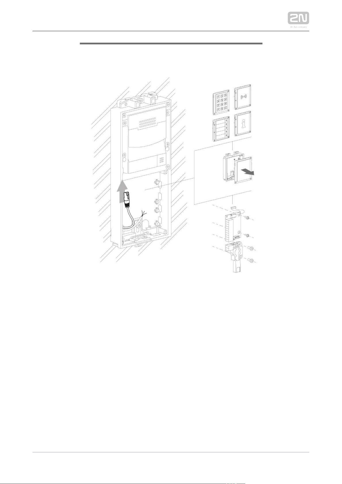
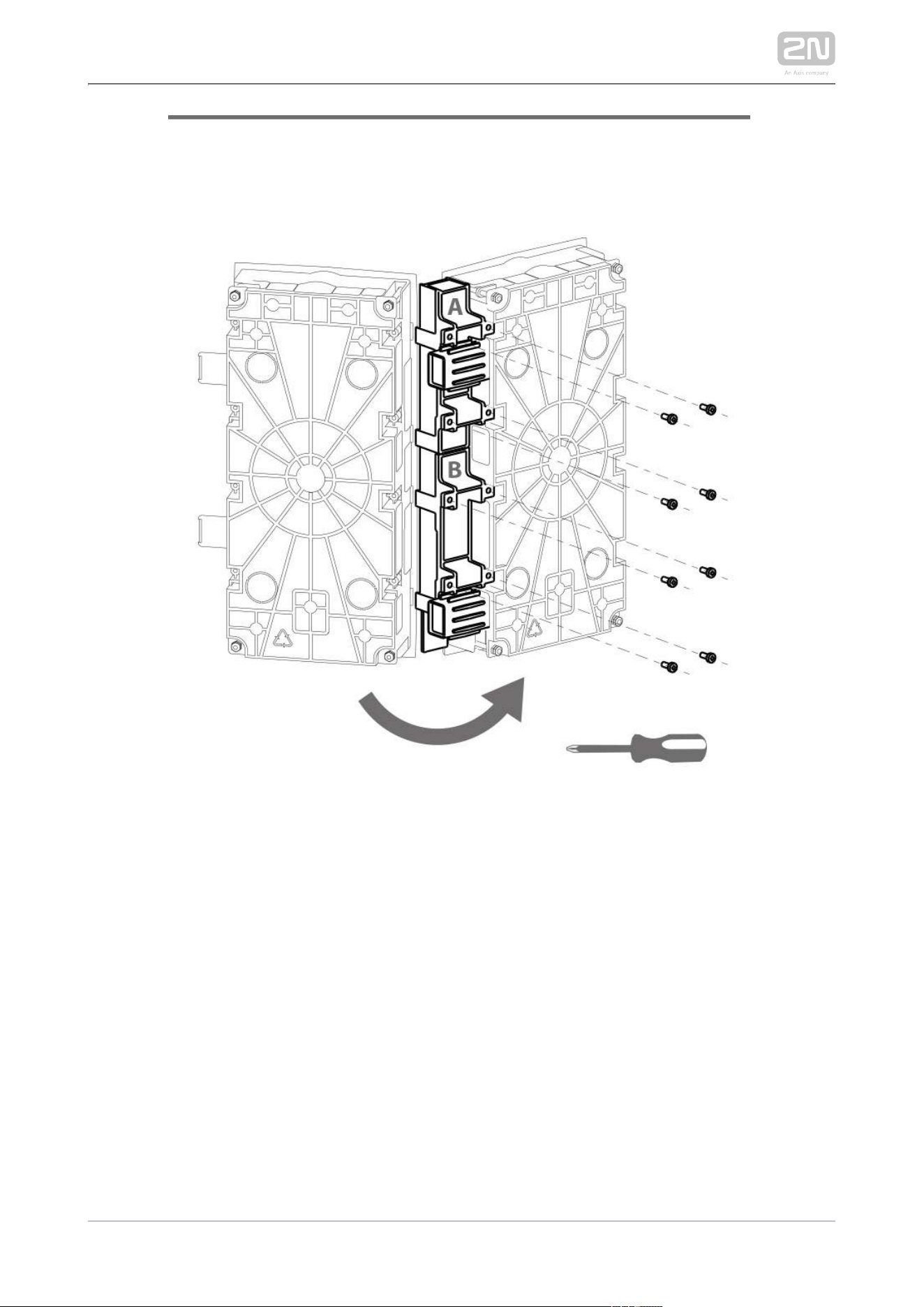
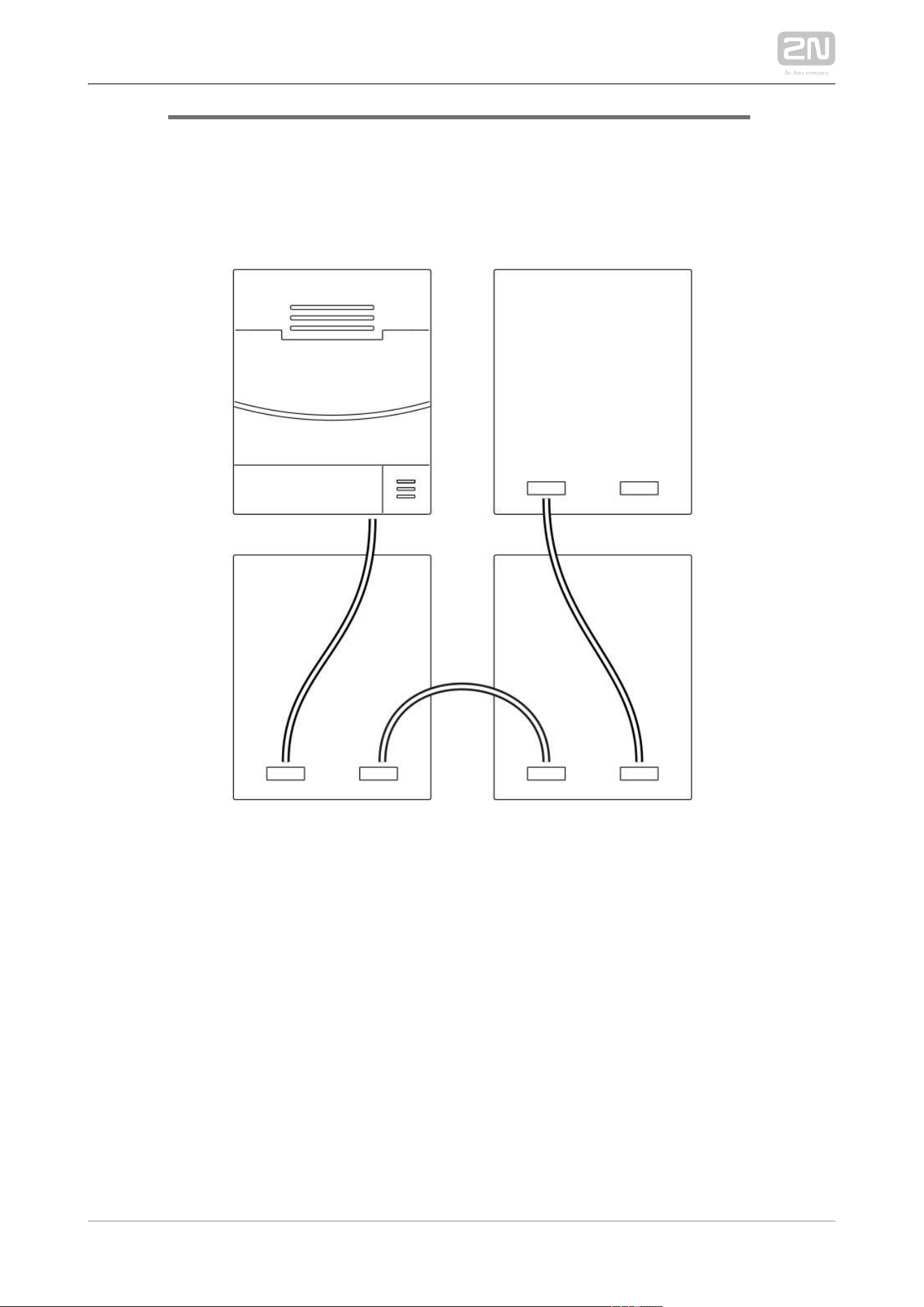
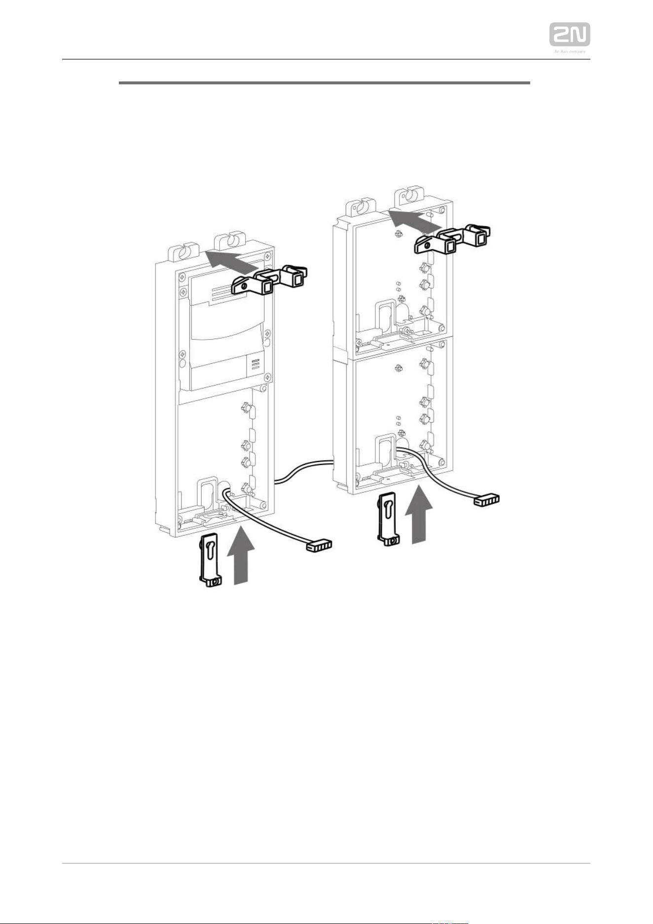
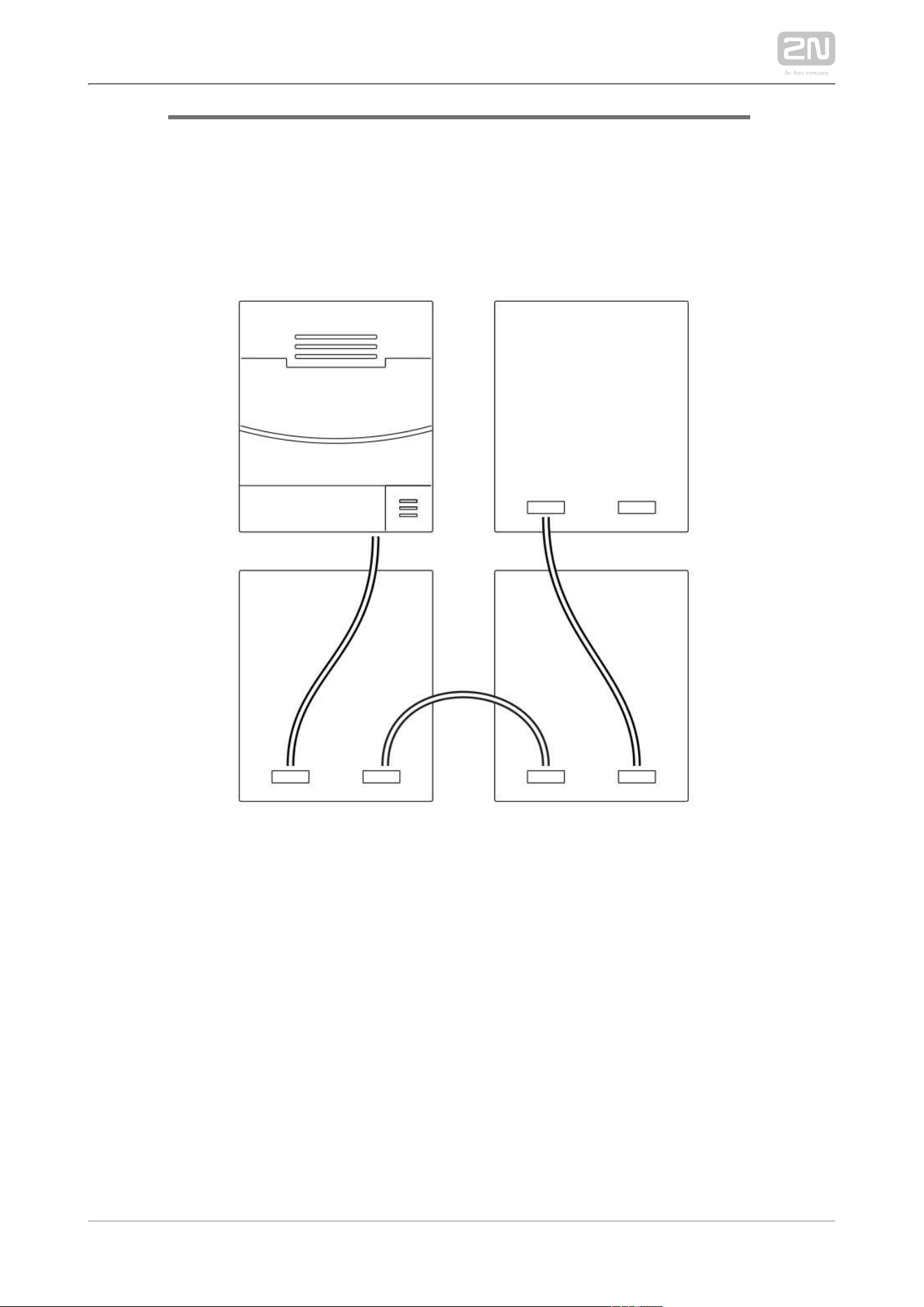
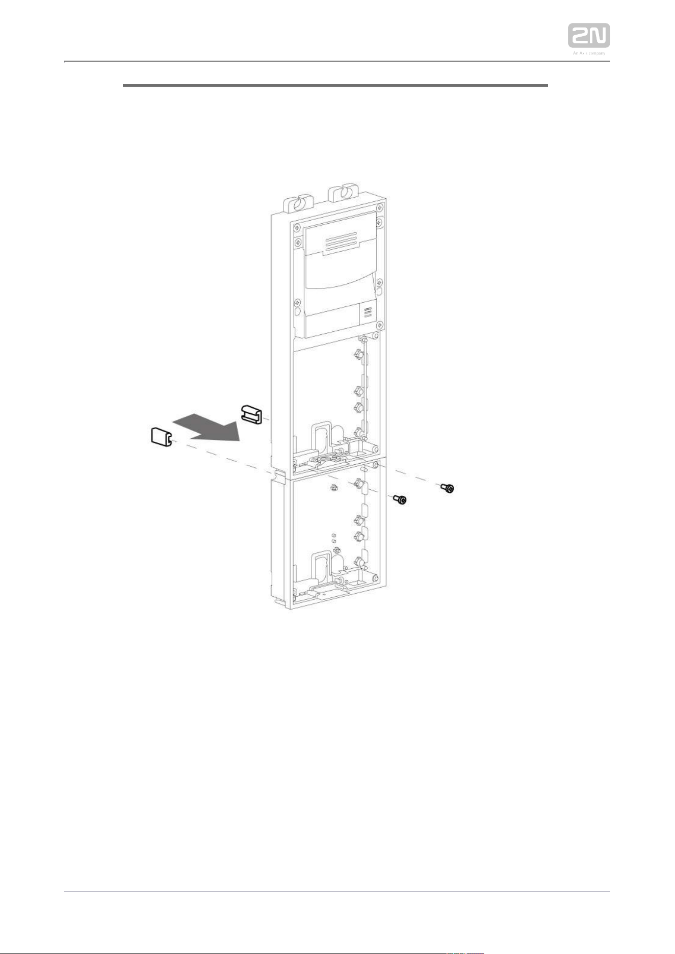
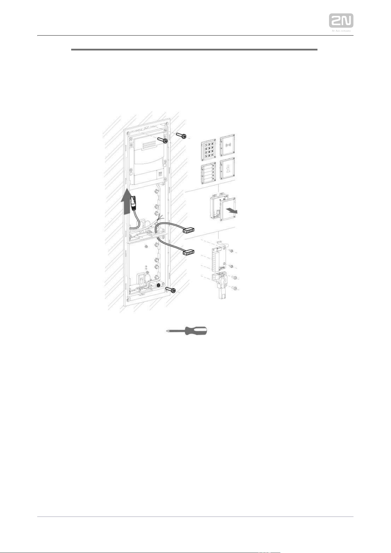
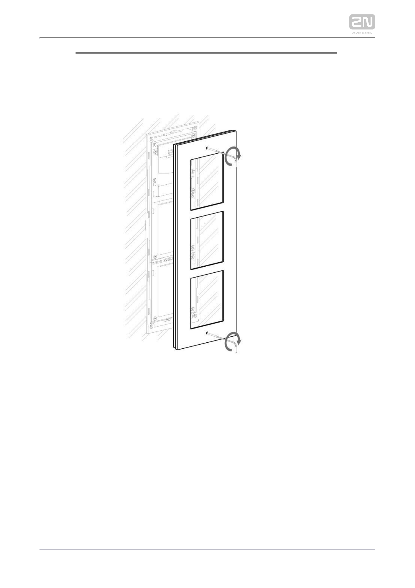
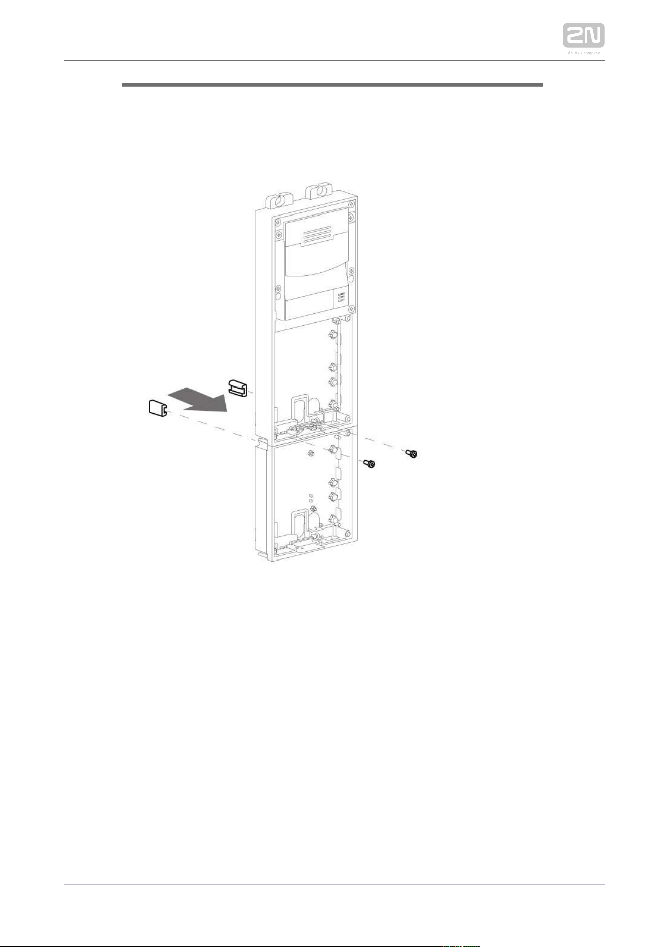
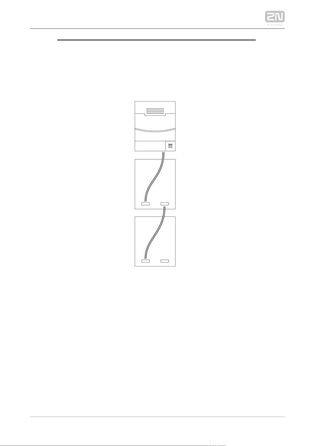
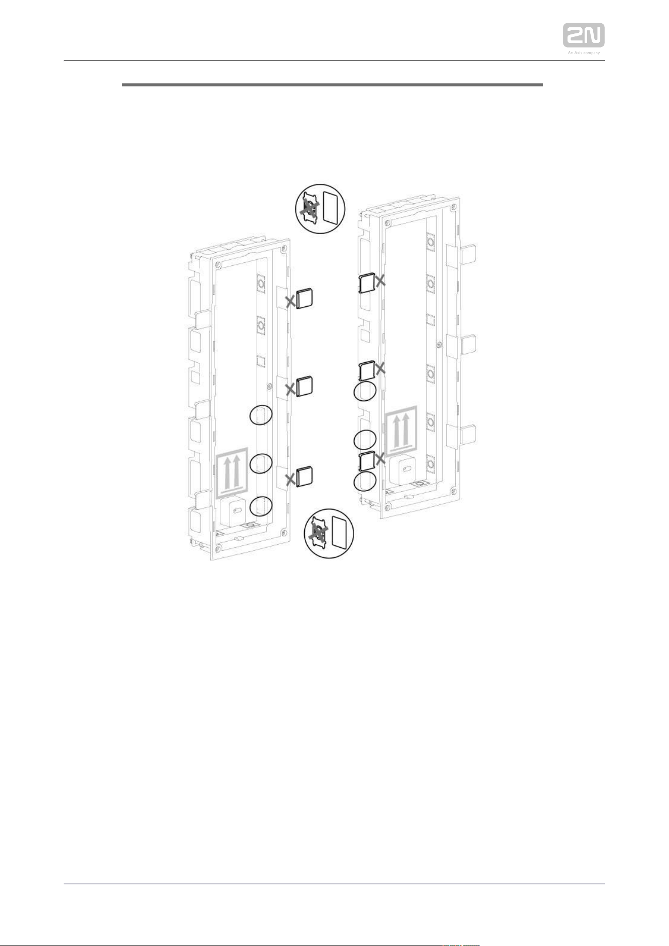
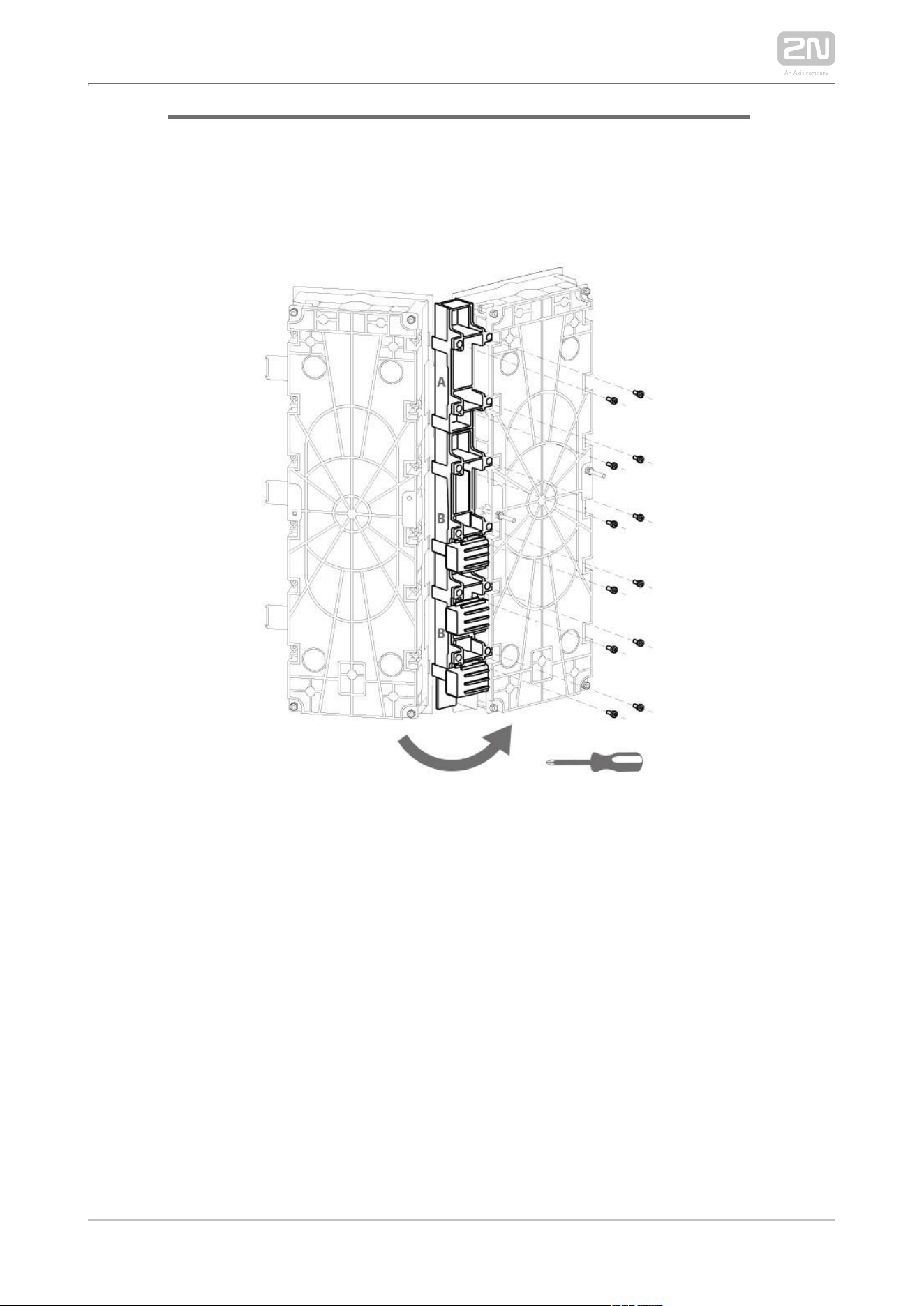
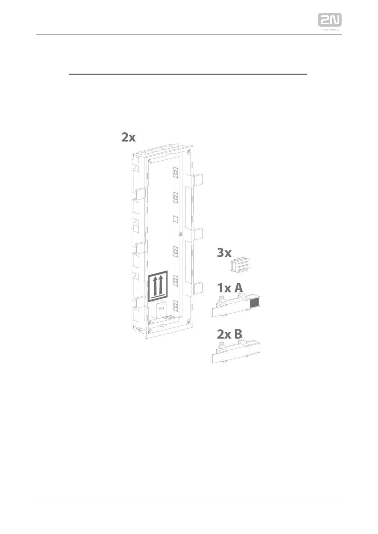
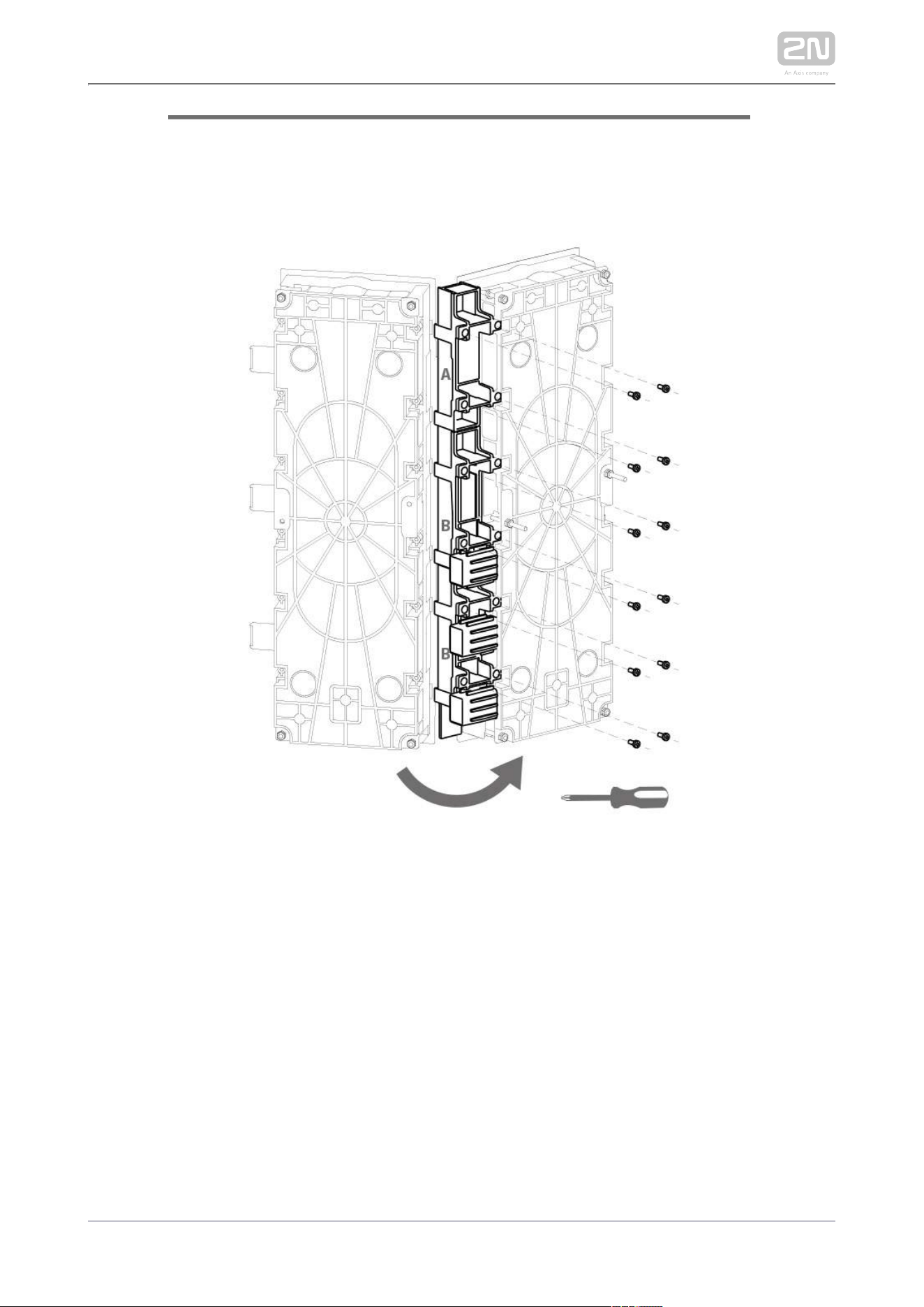
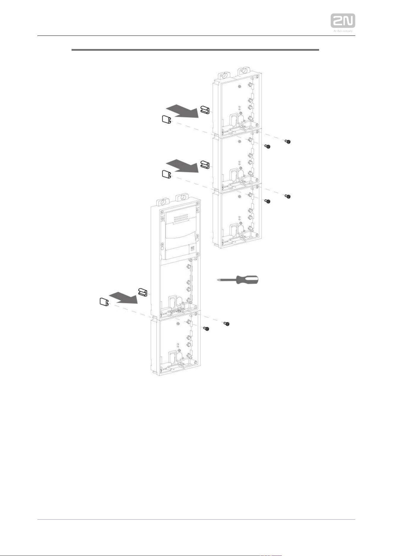
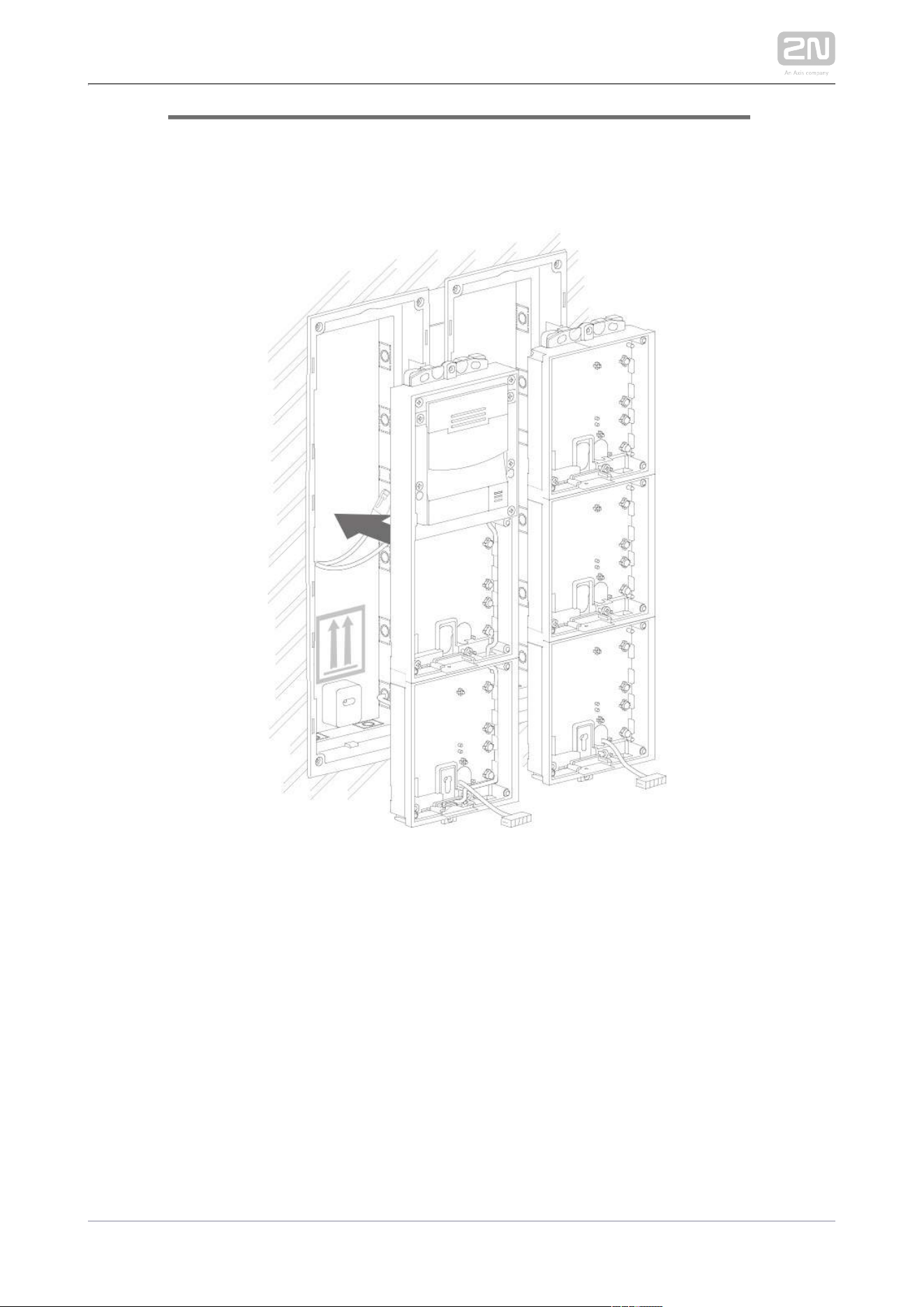
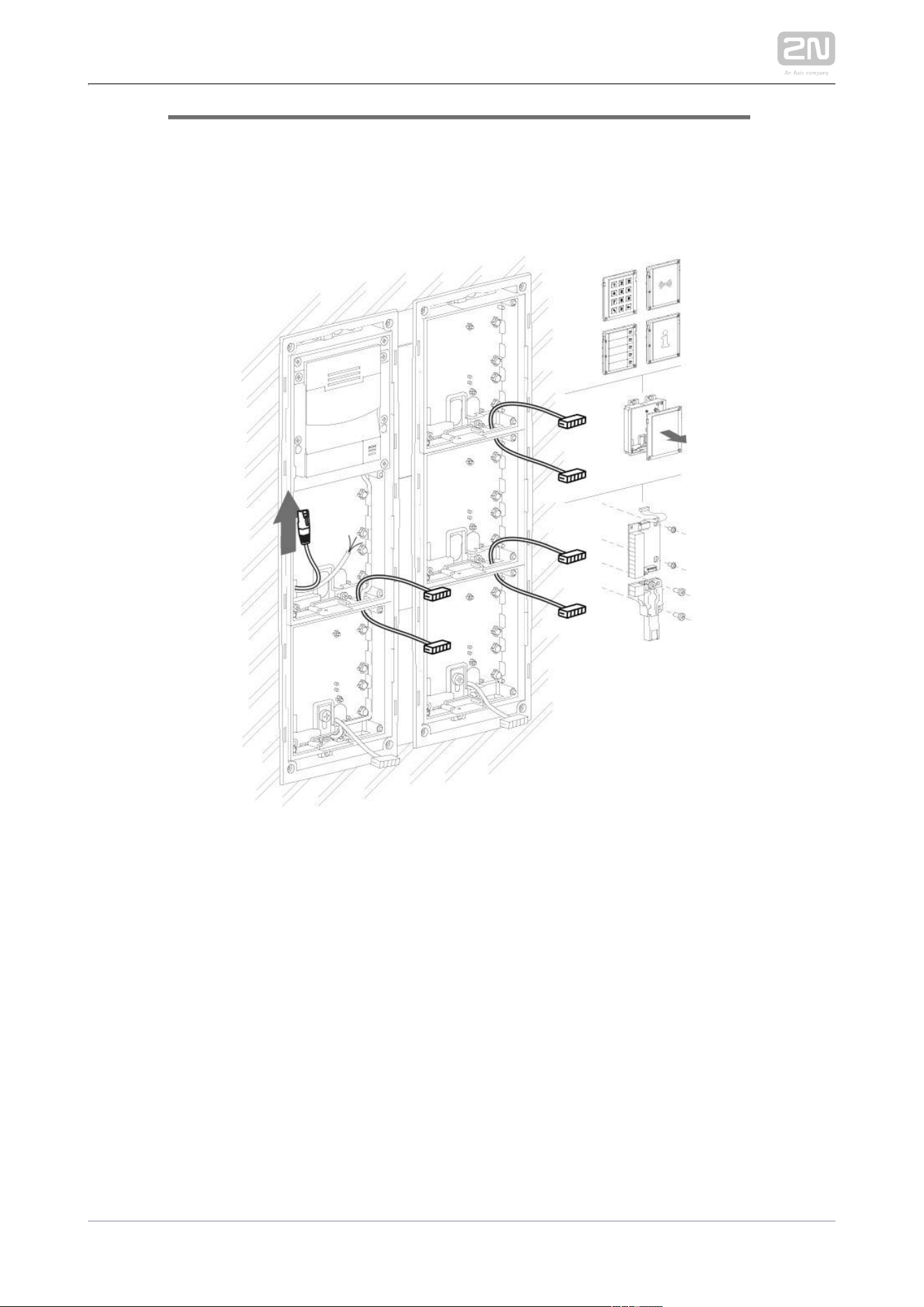
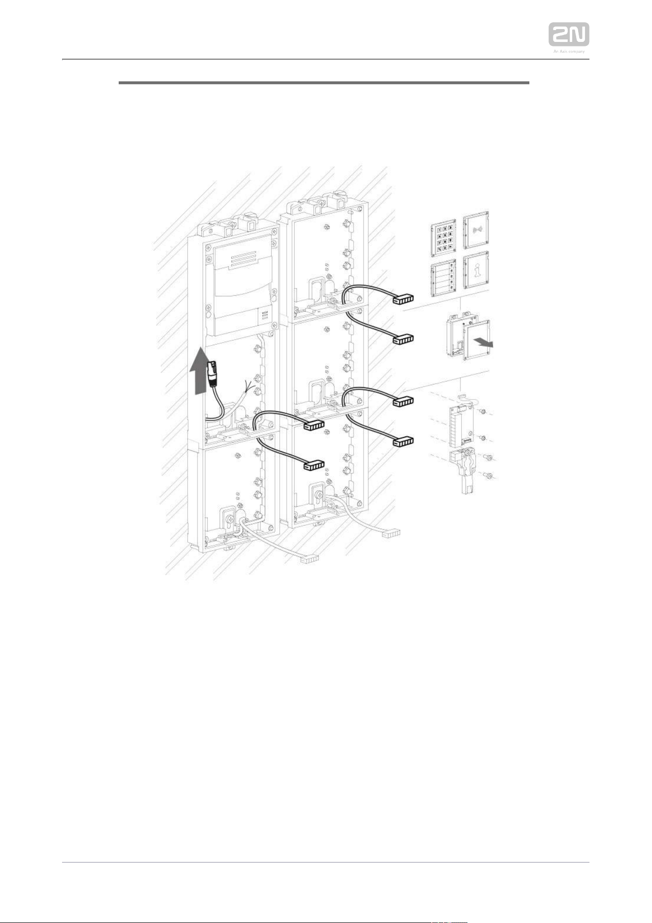
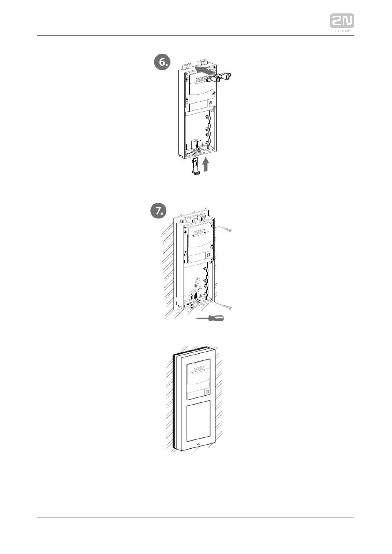
Version B – 3-Module Base
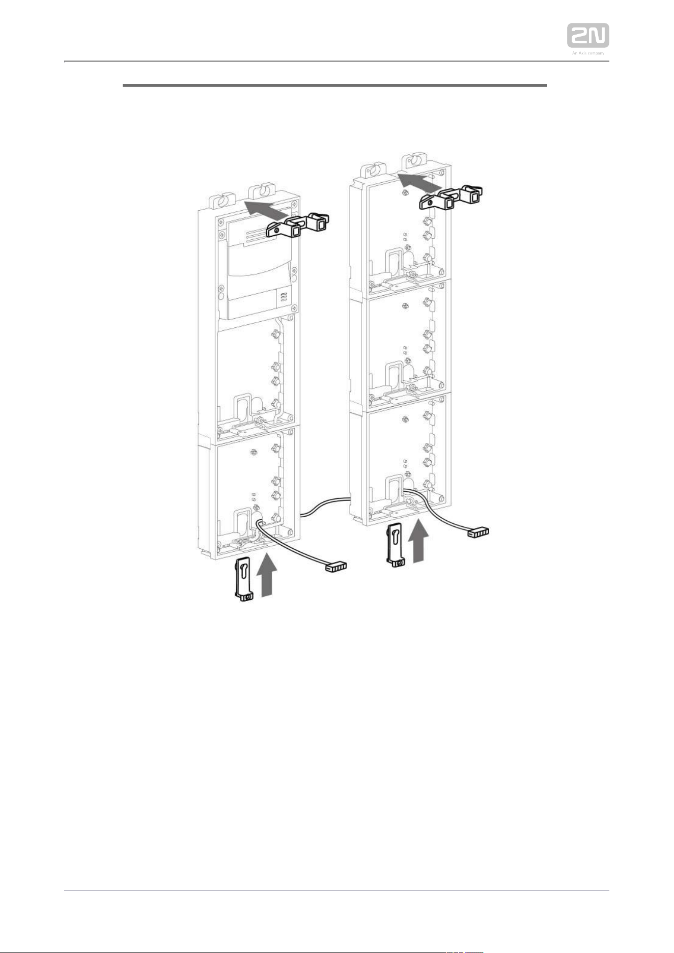
Unscrew the cover of the additional base.
Use a flat screwdriver to take out the cover.
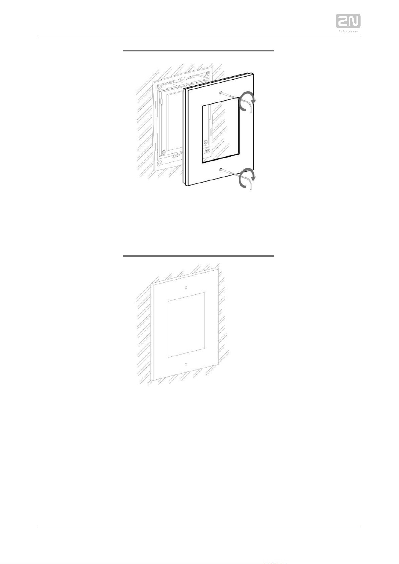
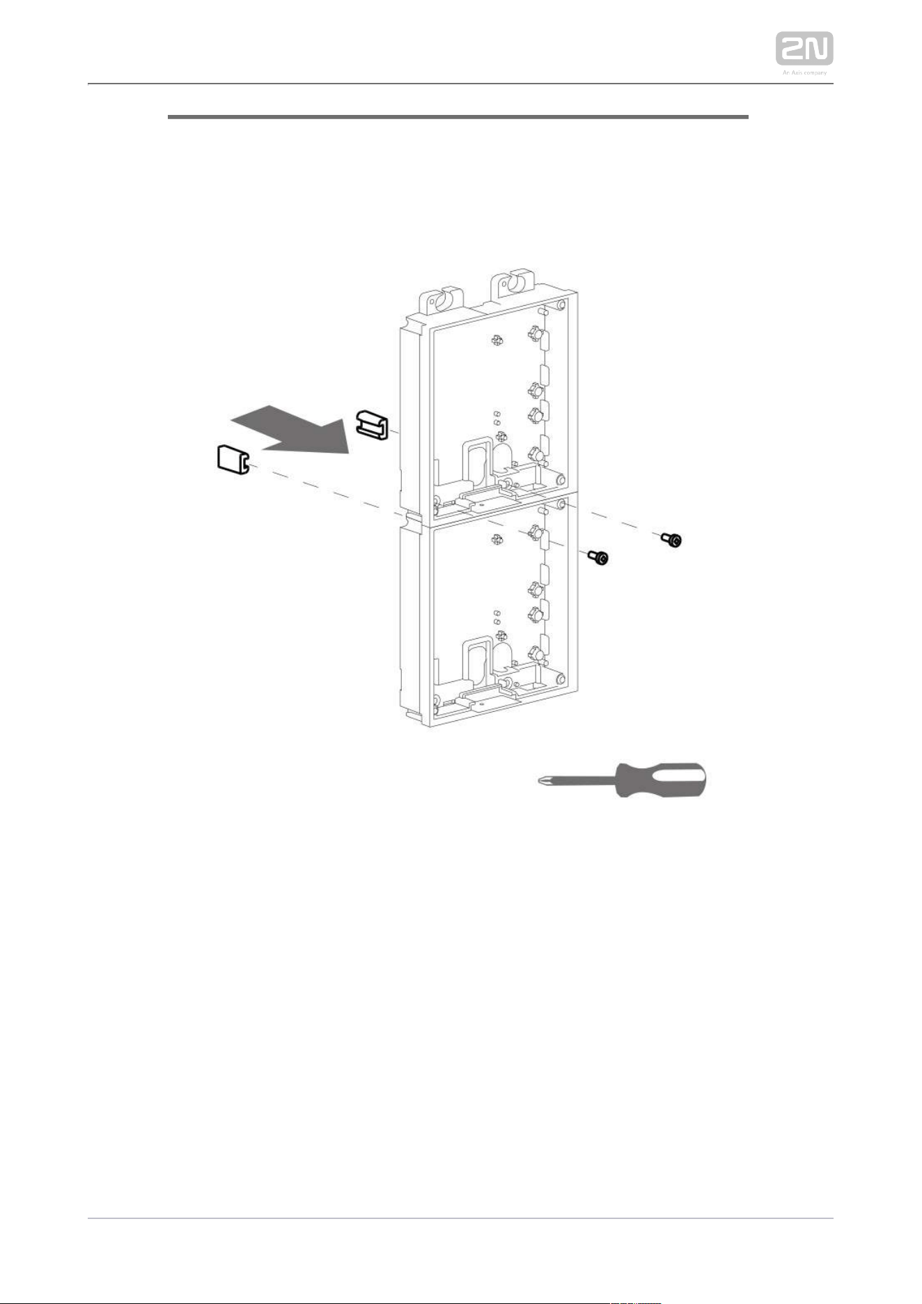
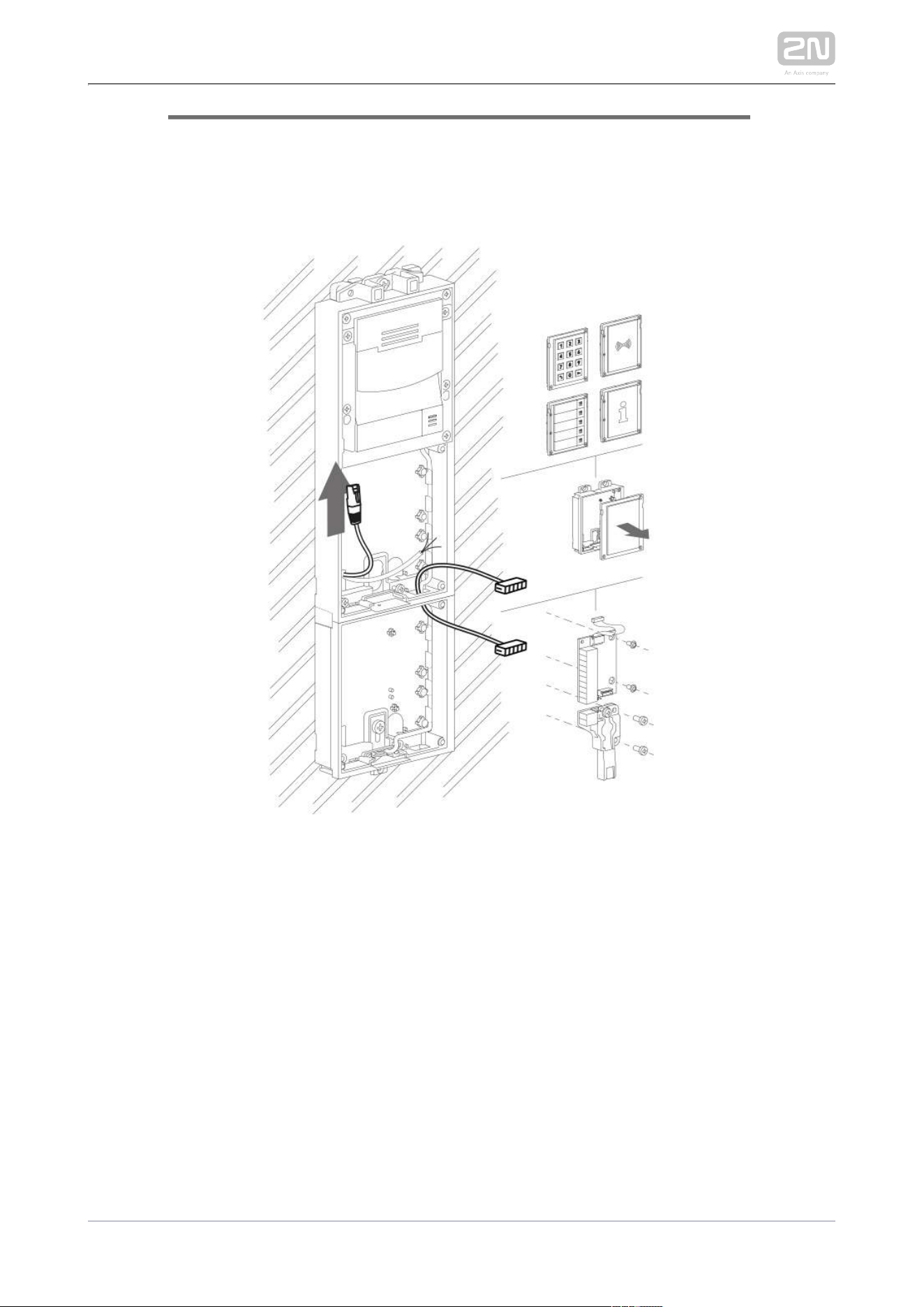
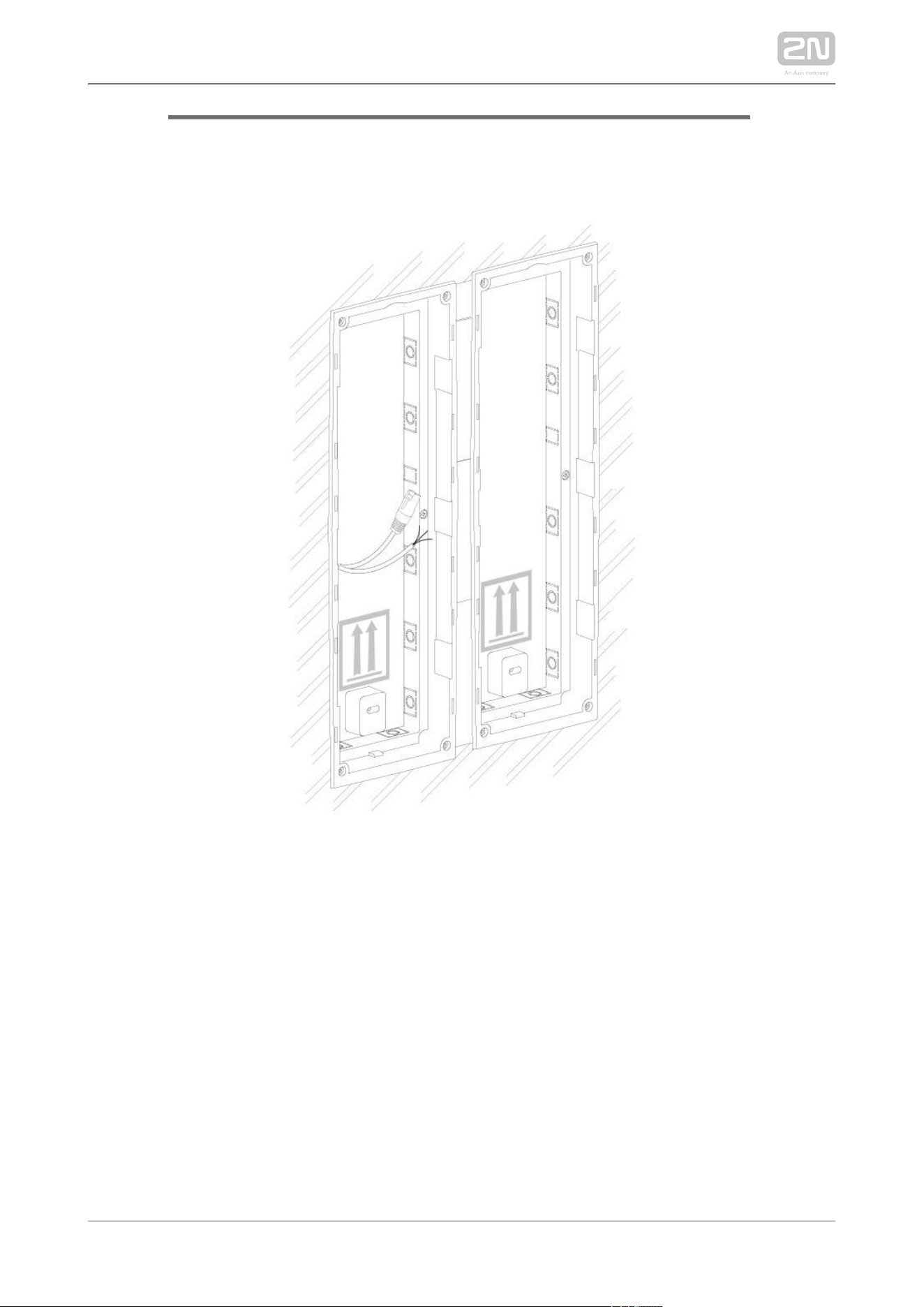
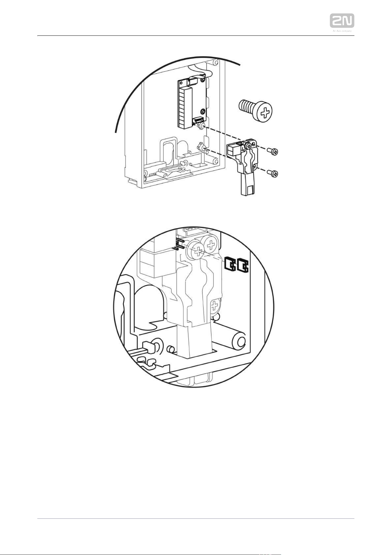
Slide the additional base to the main unit base and secure its position with the
small side wedges and screws.
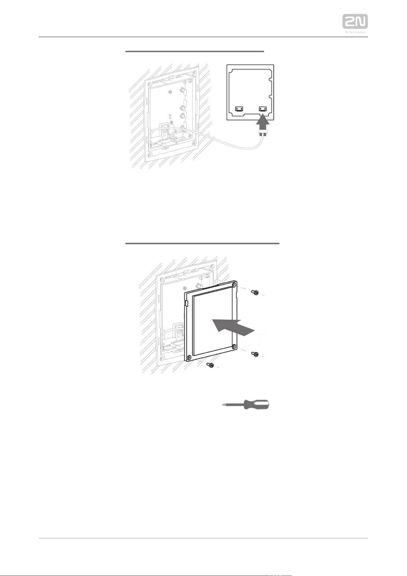
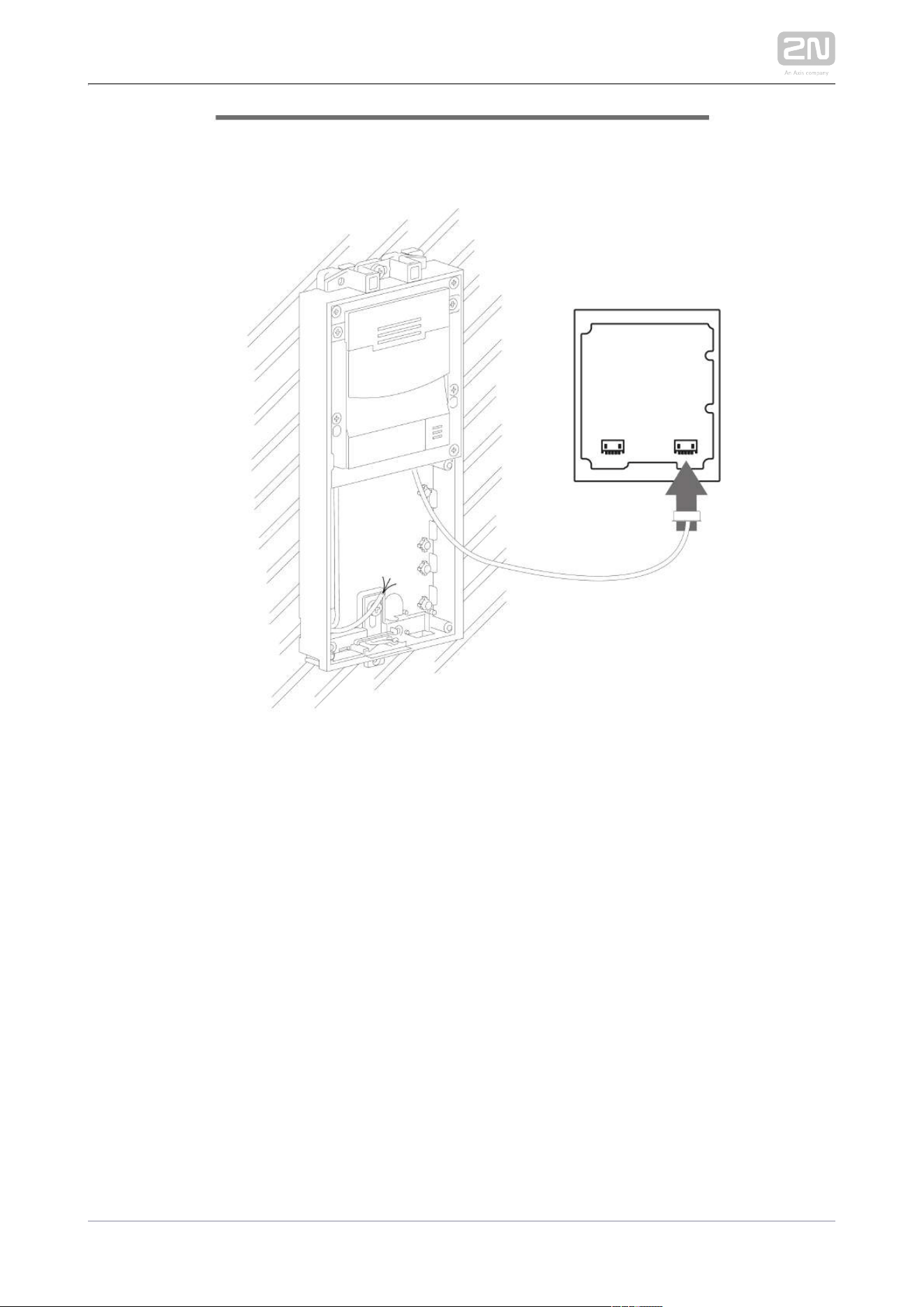
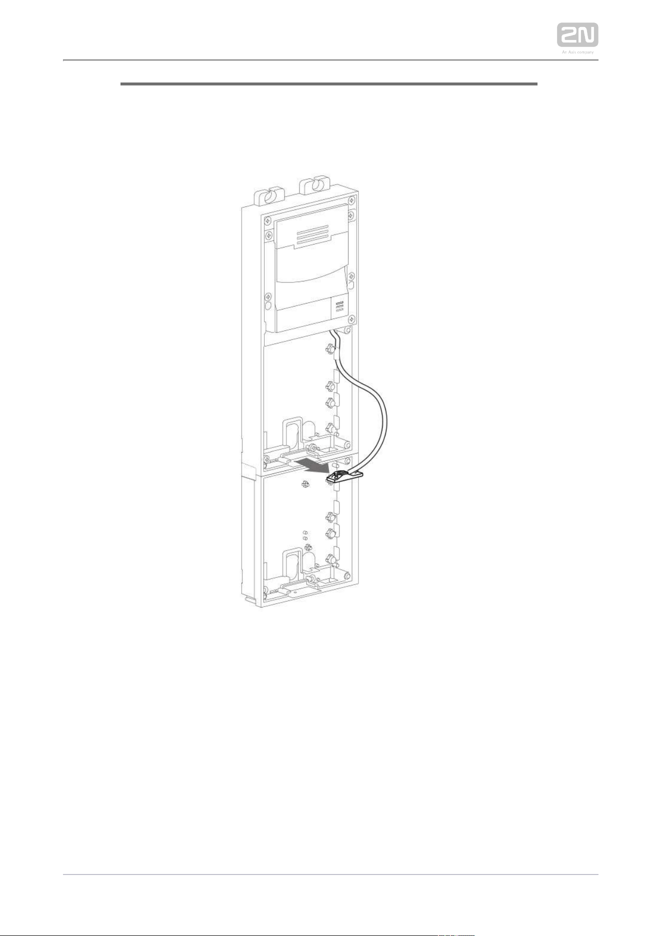
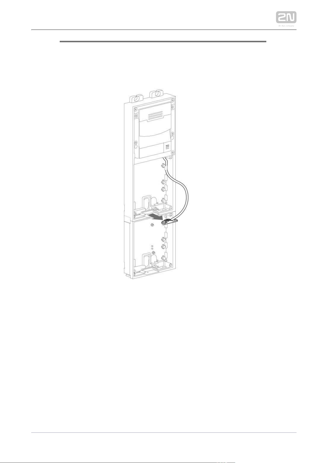
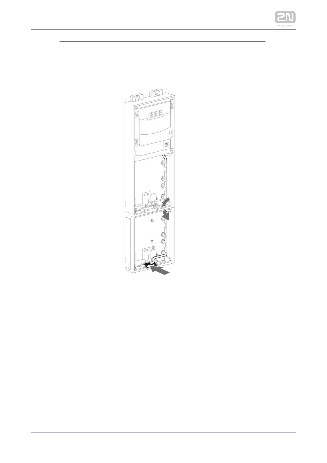
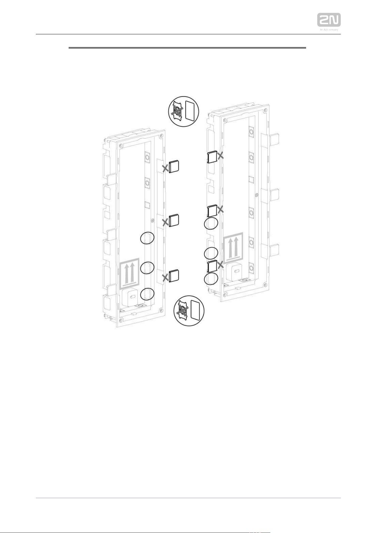
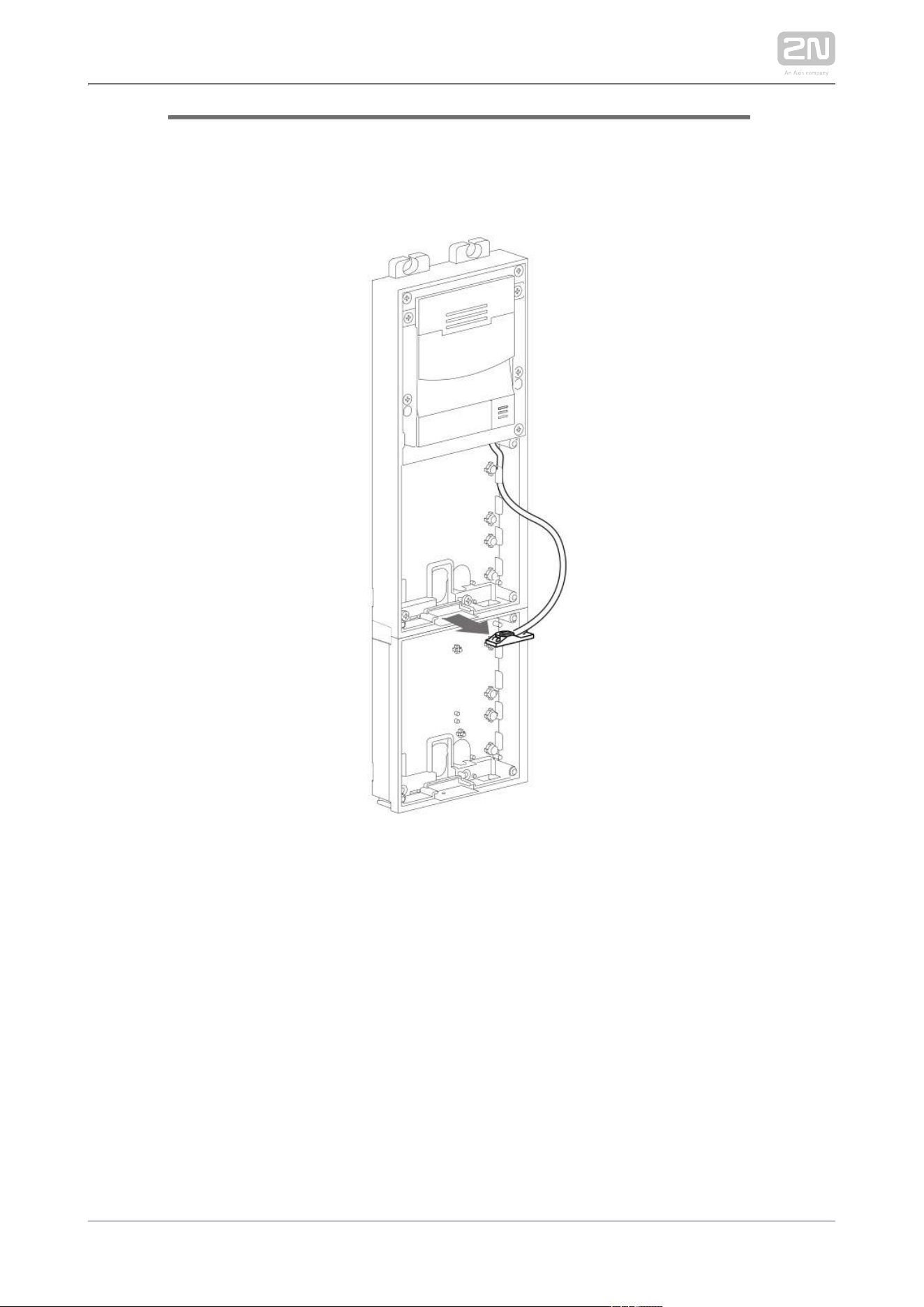
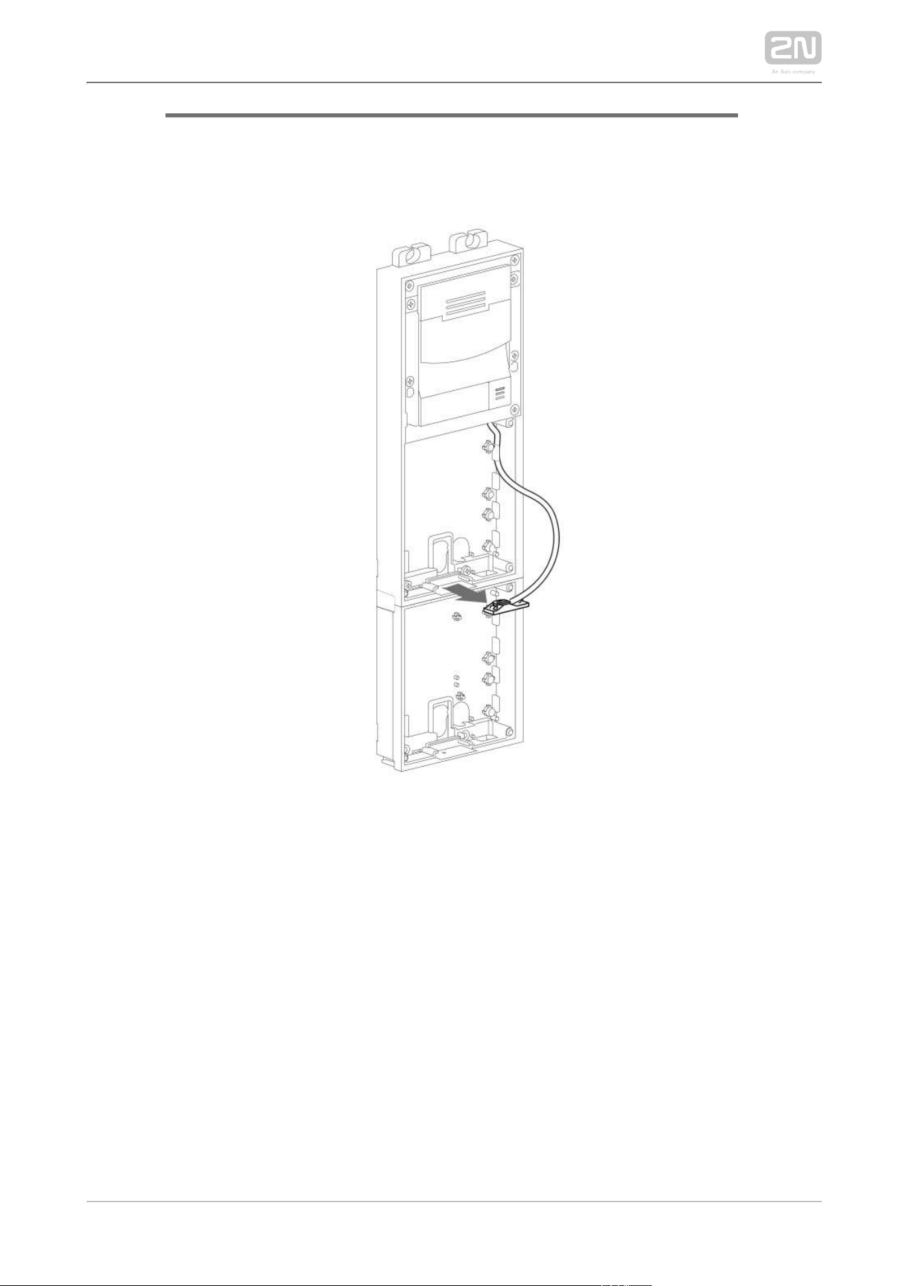
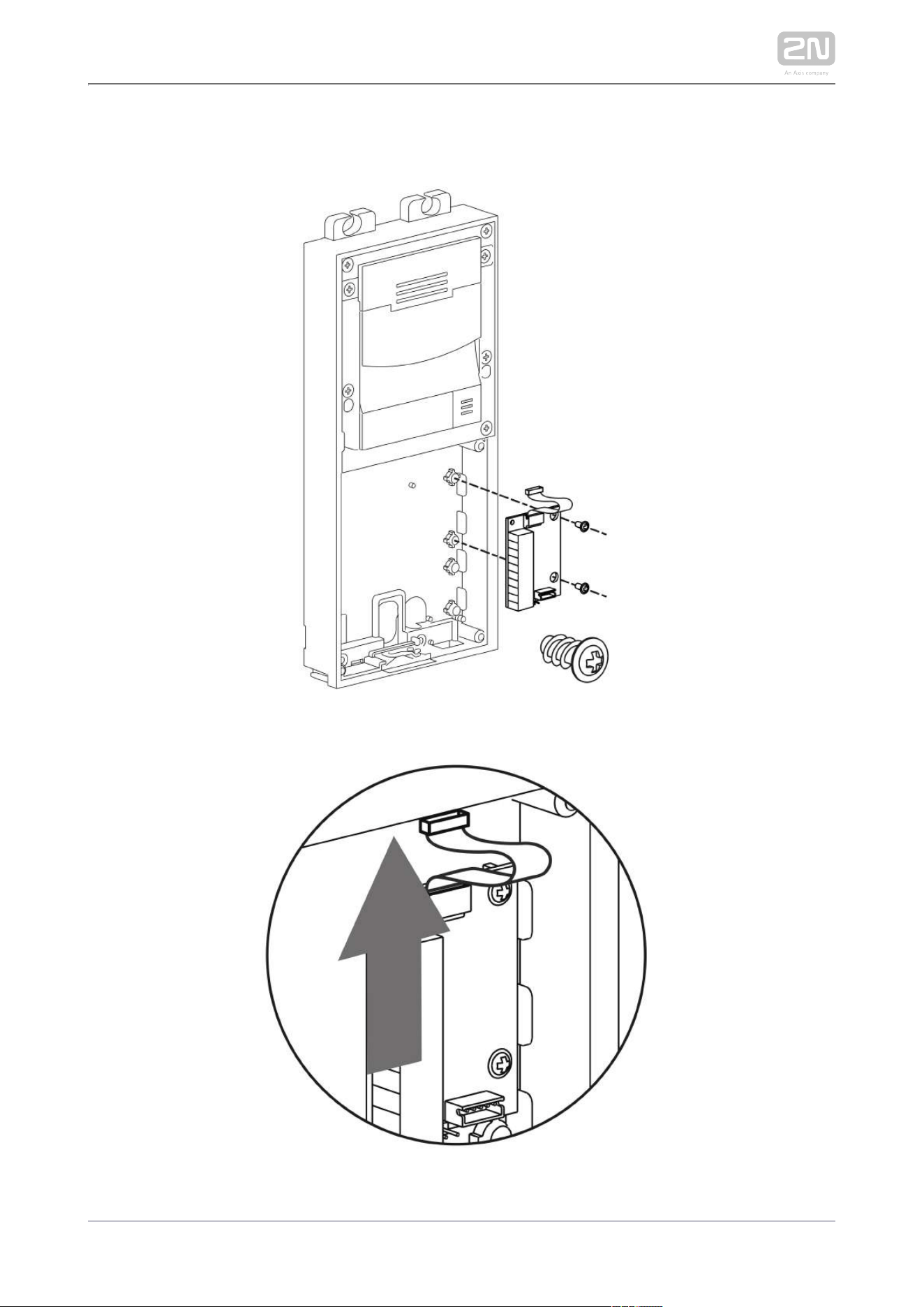
Remove the microphone from the main unit base and loosen the microphone
cable.
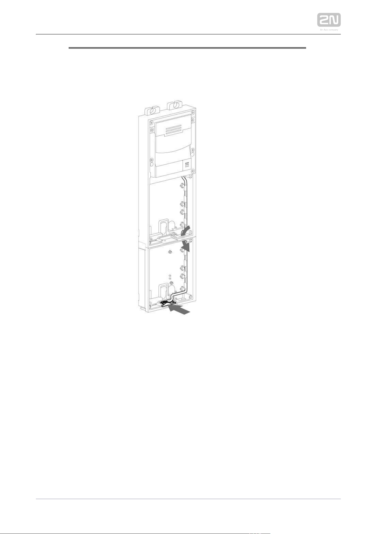
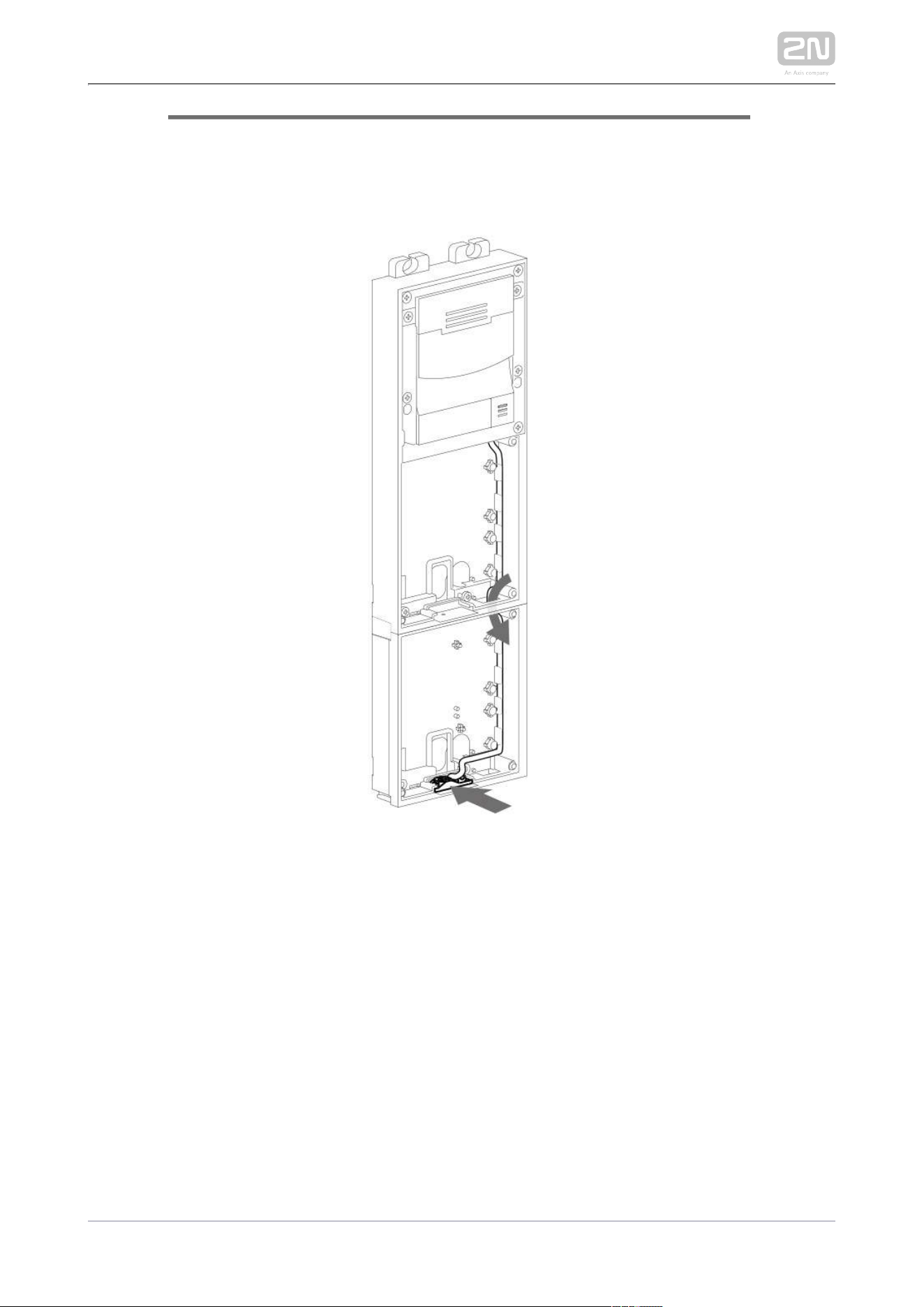
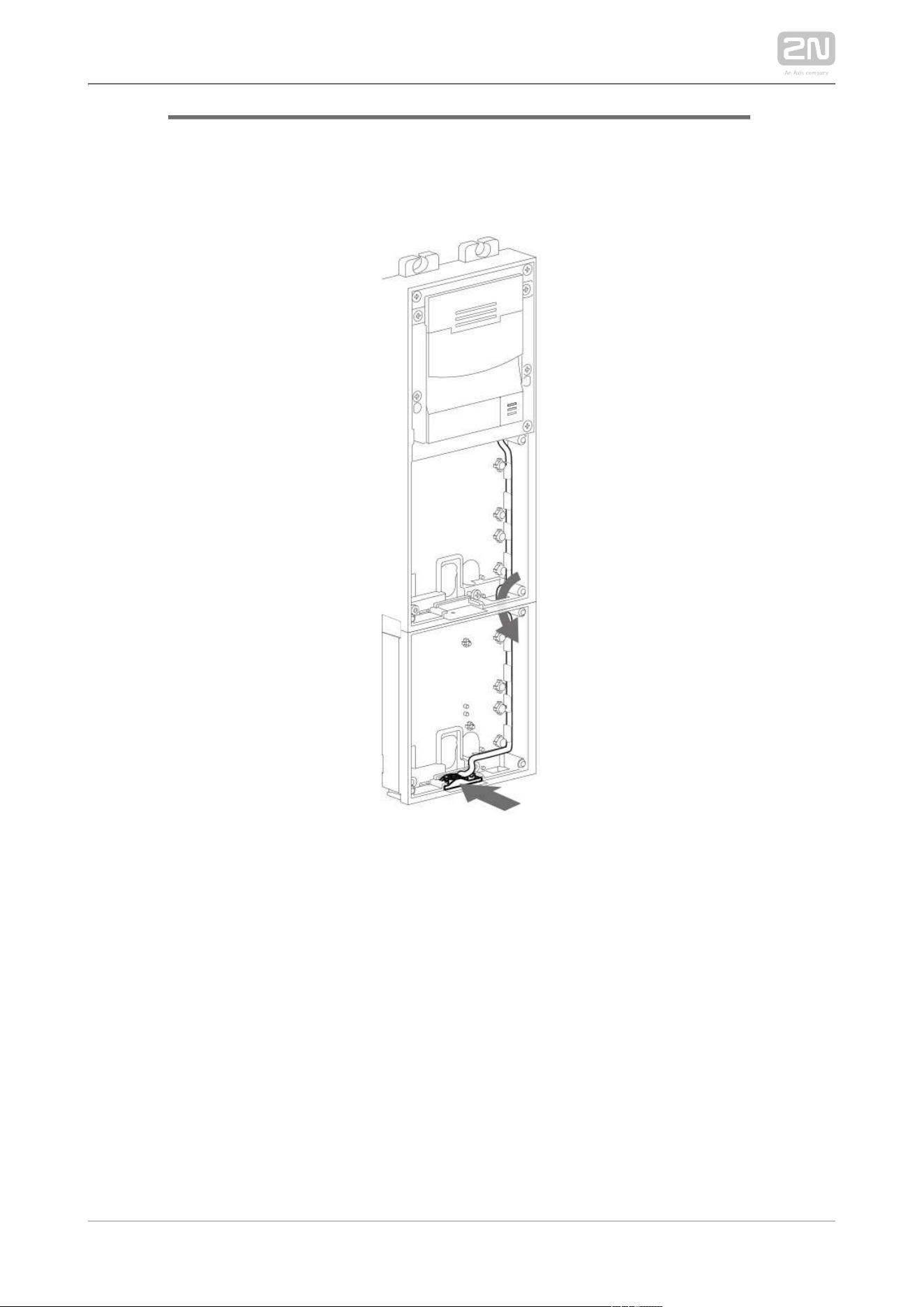
Lead the microphone to the third module base as shown in the figure.
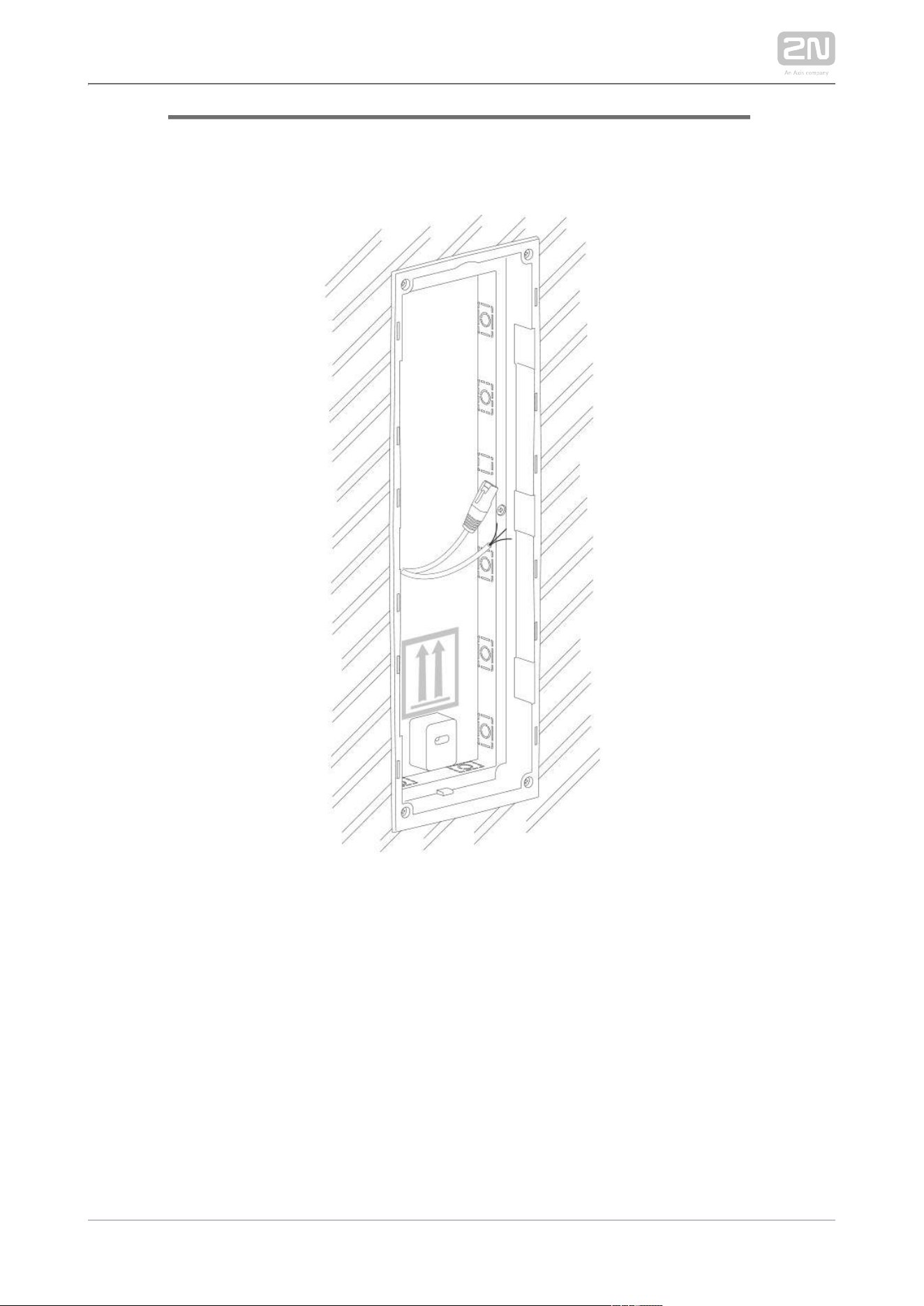
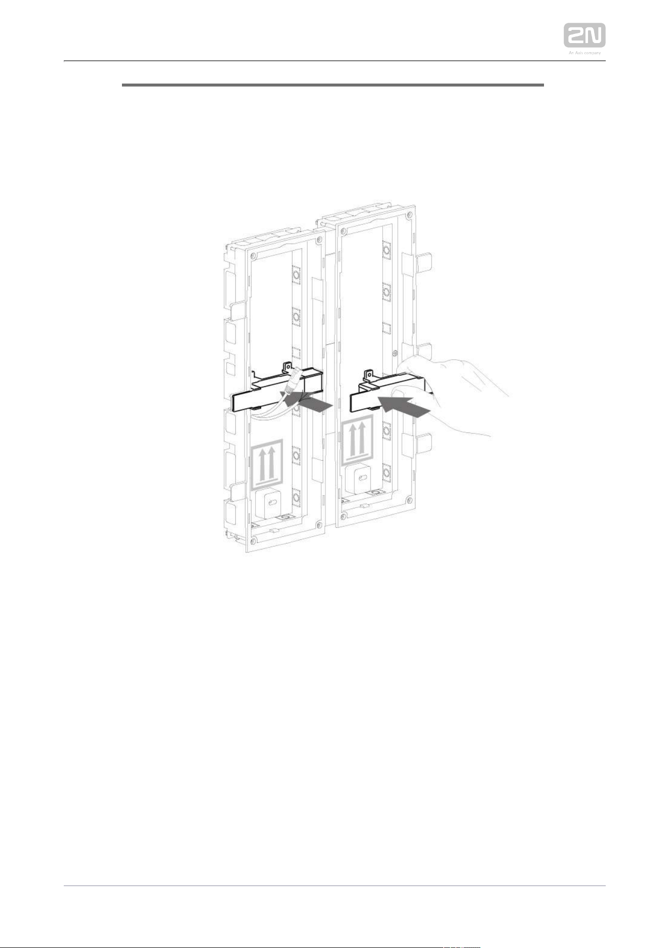
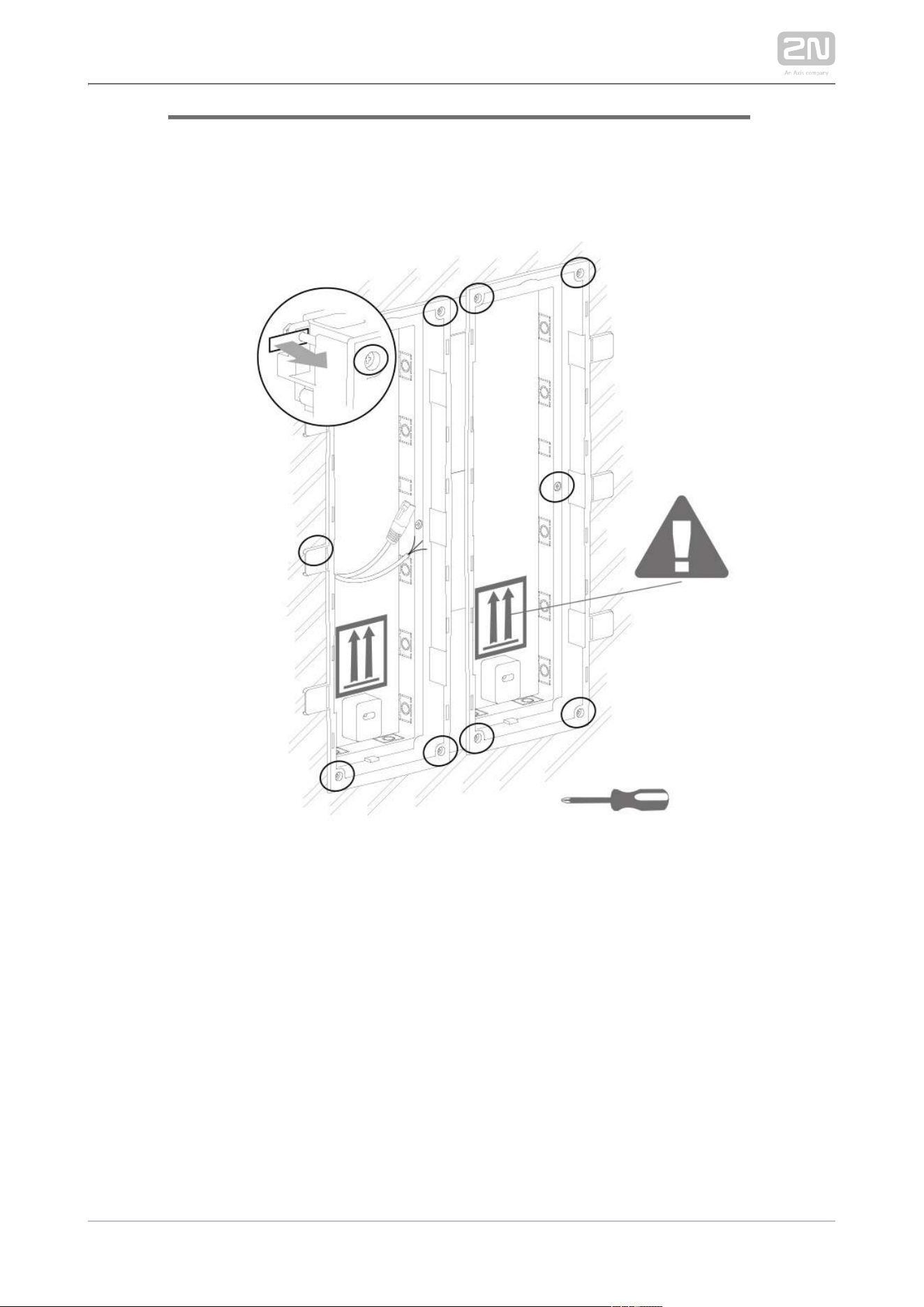
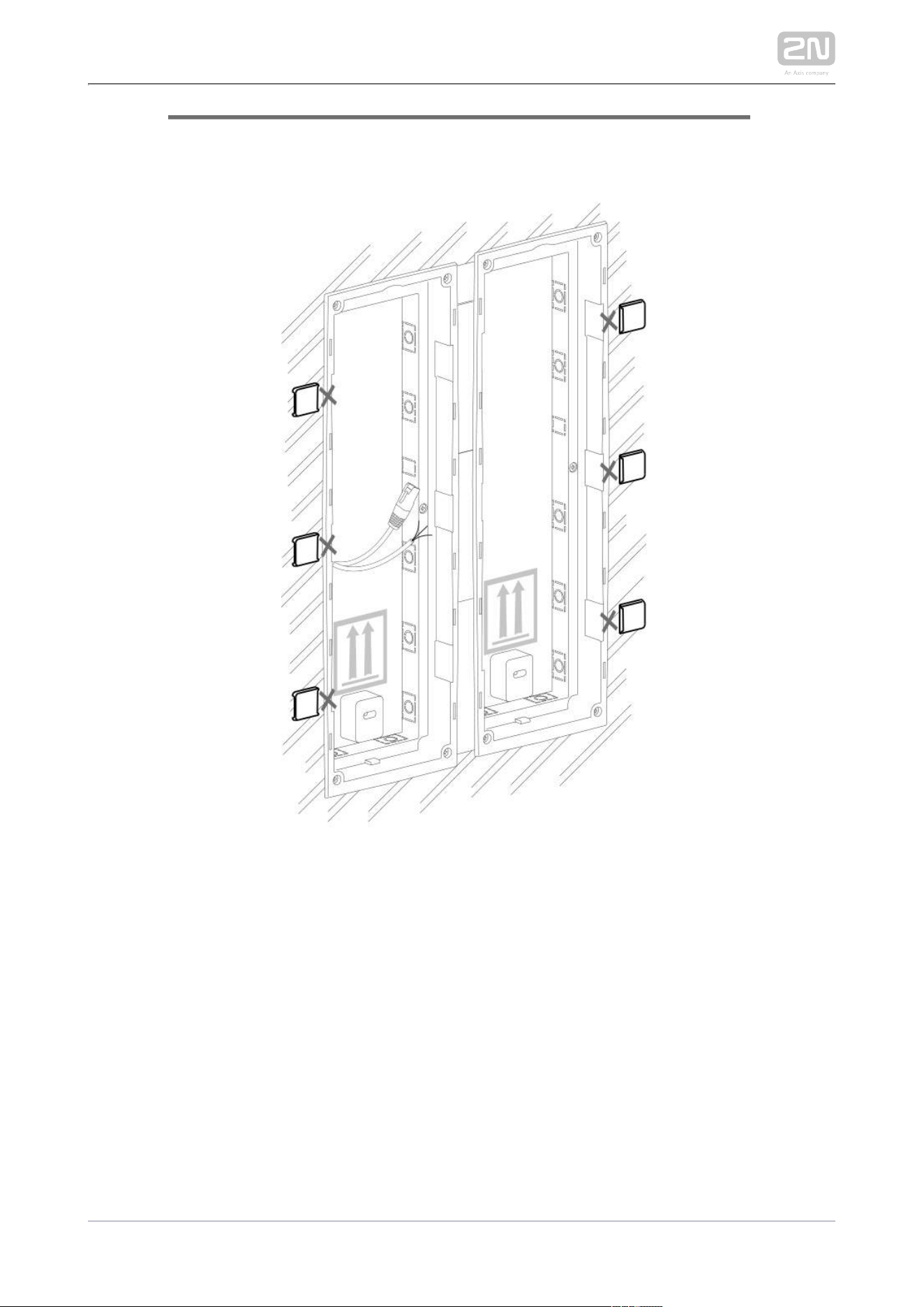
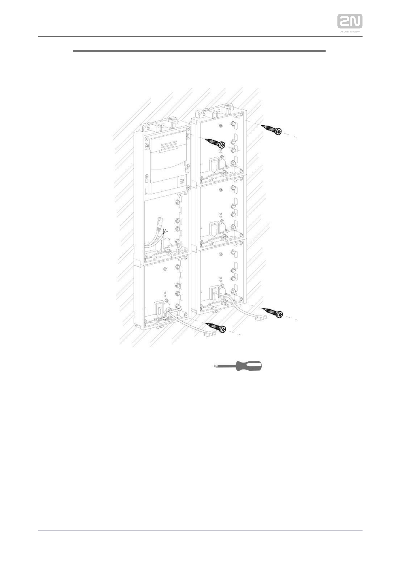
Place the joined bases on the flush mounting box / predrilled holes with dowels
and pull the cables through the bottom holes. Feed the Ethernet cable without
the connector from the additional base to the main unit base if necessary.

2N TELEKOMUNIKACE a.s., www.2n.cz 251/319
1.
2.
3.
4.
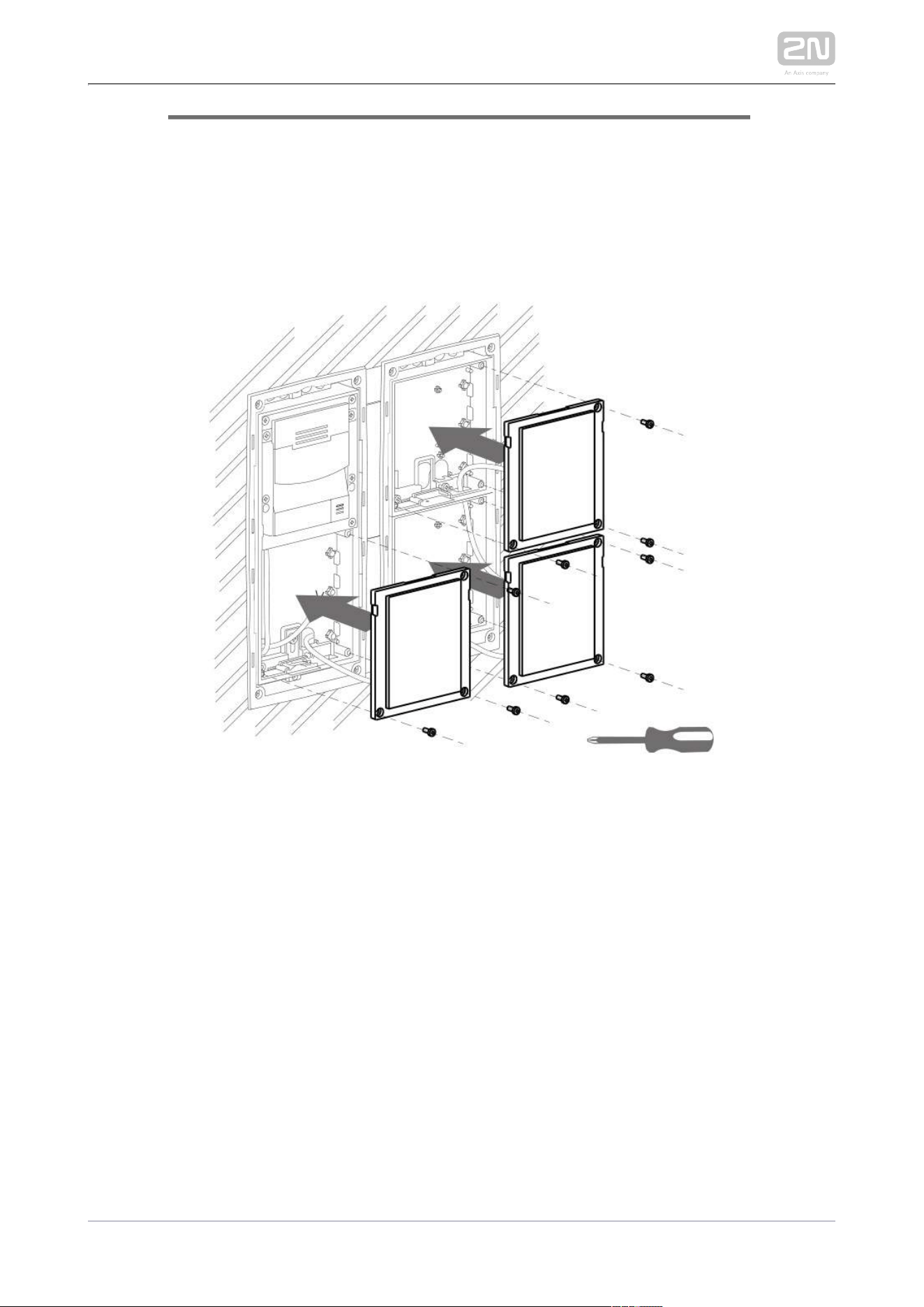
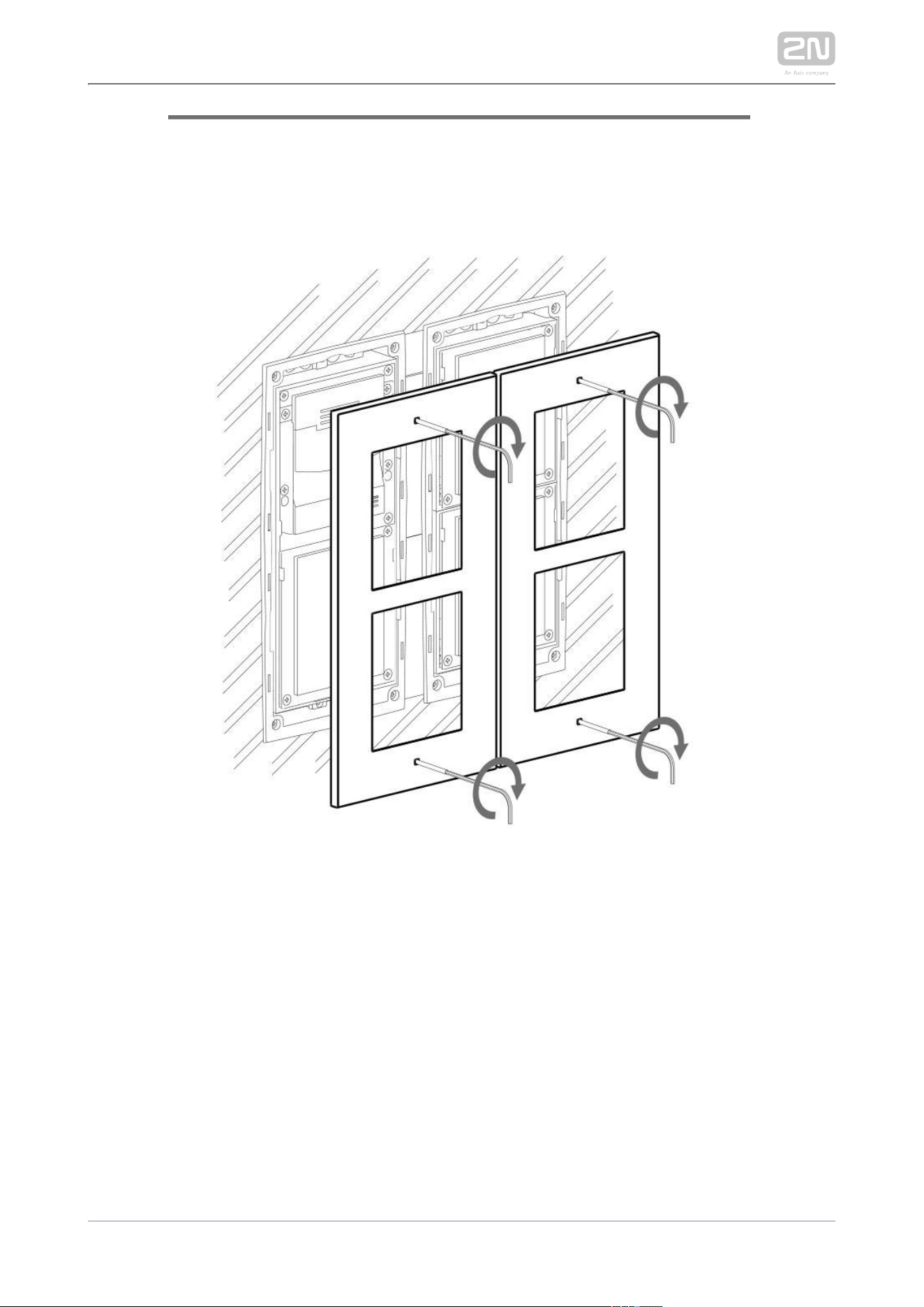
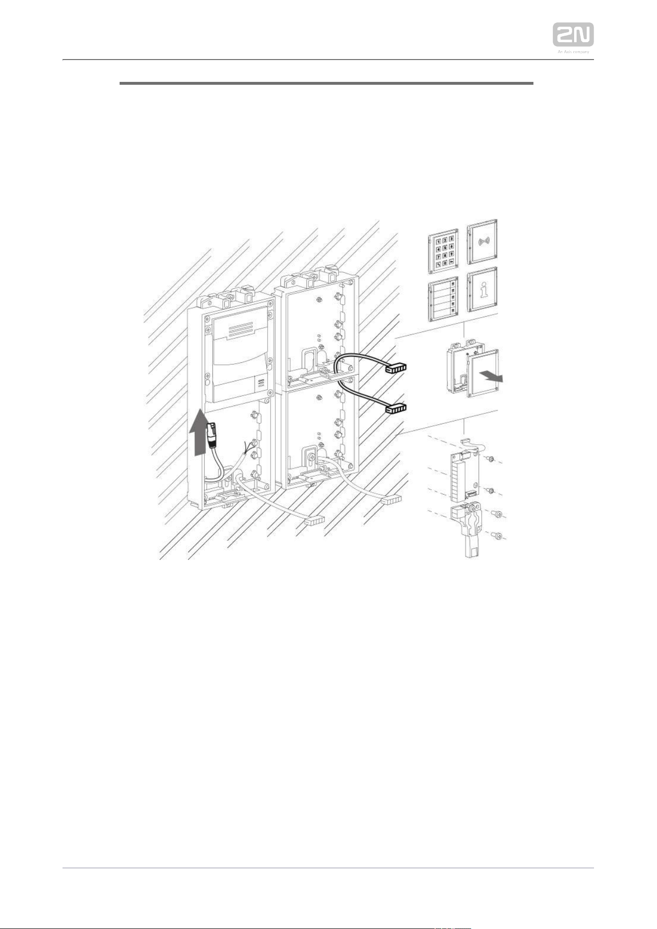
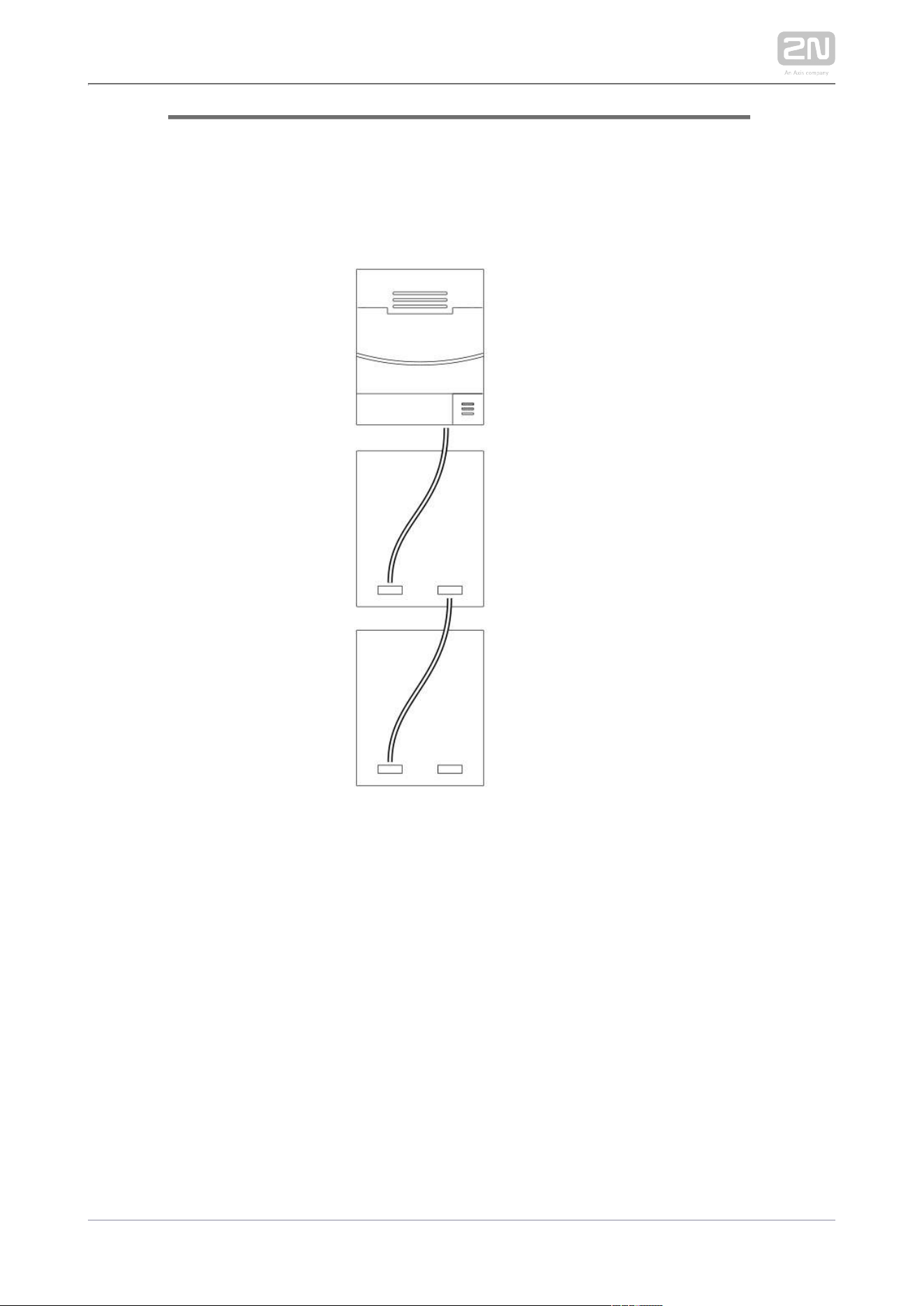
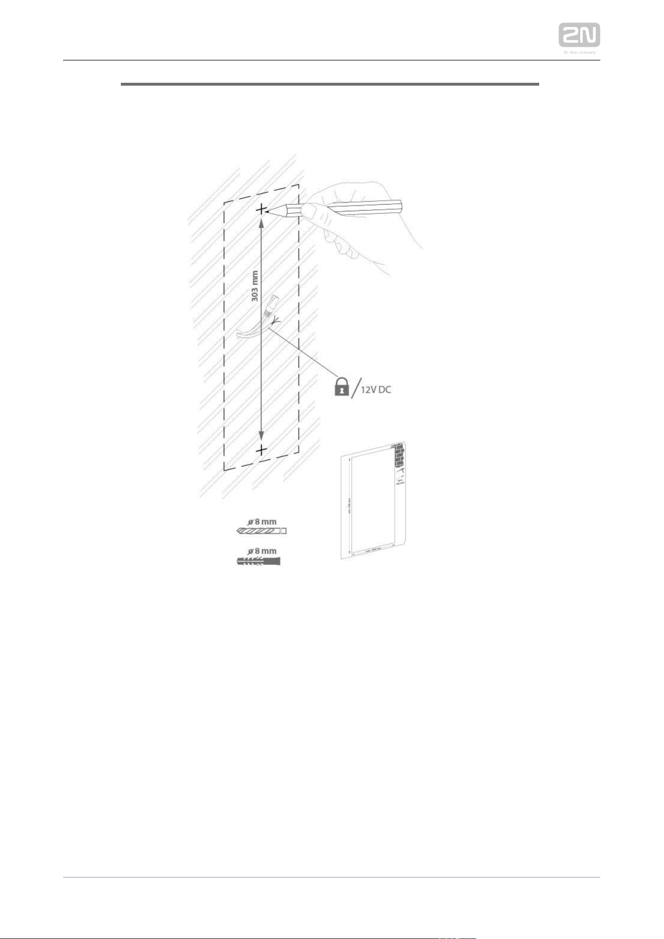
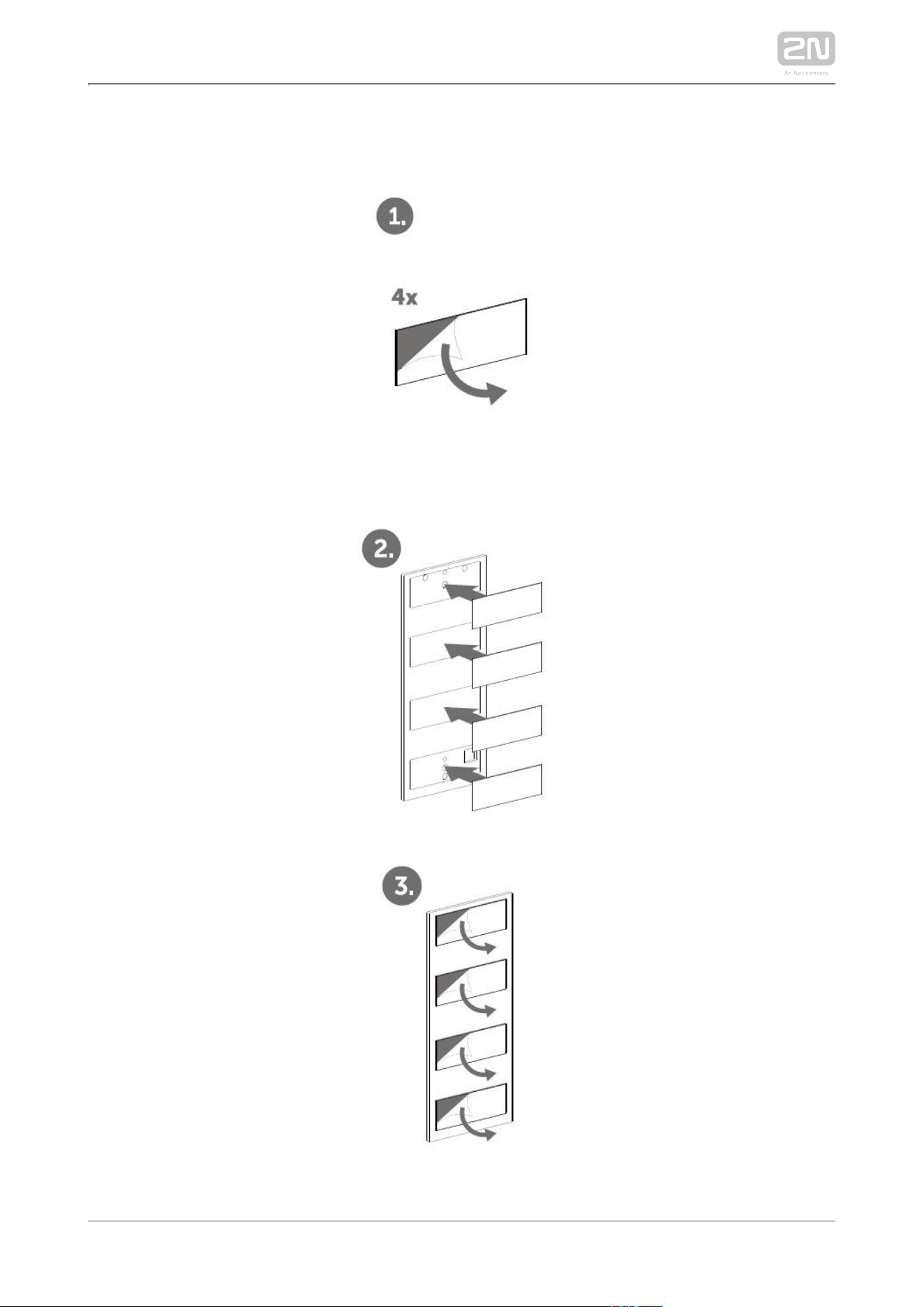
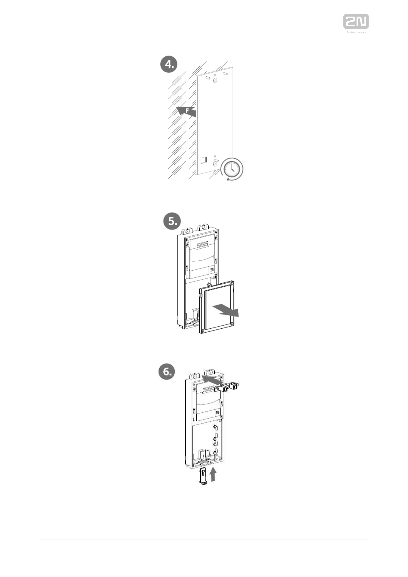
Version C – Additional Columns
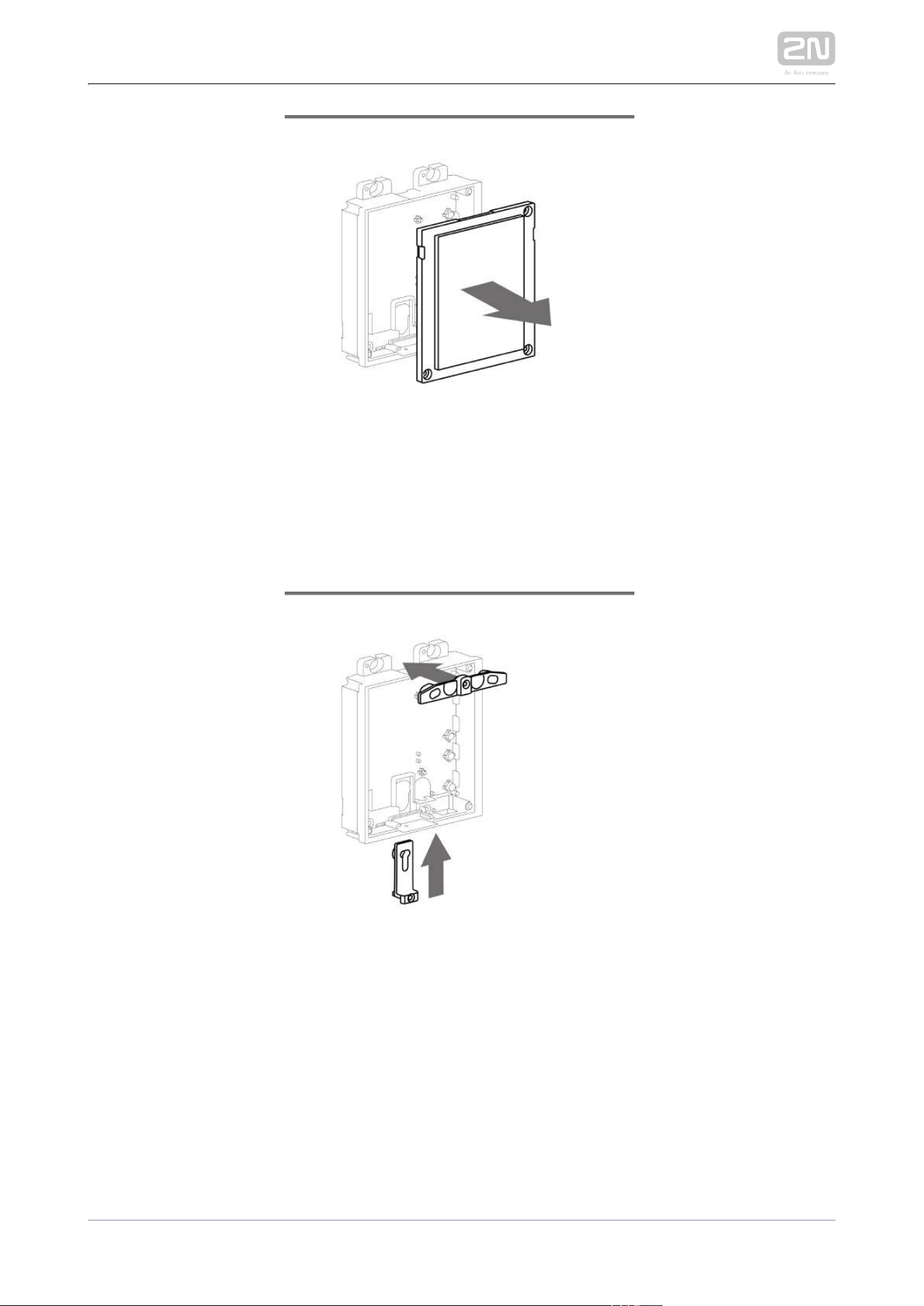
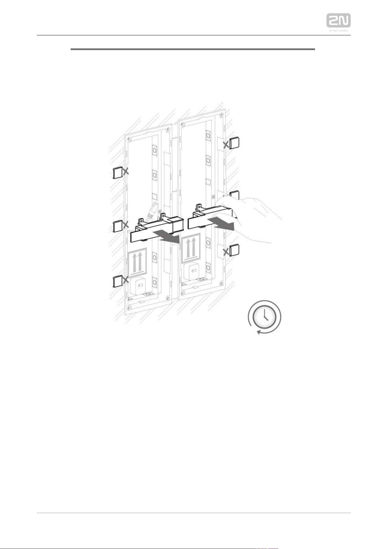
Unscrew the cover of the additional bases and take it out with a flat screwdriver.
Insert the bases into each other as projected and secure their position with the
small side wedges and screws.
Place the cover on the flush mounting box / predrilled holes with dowels and pull
the cables if any through the bottom holes.
Pull the bus using the cable bushing available in the flush mounting box.
Main Unit
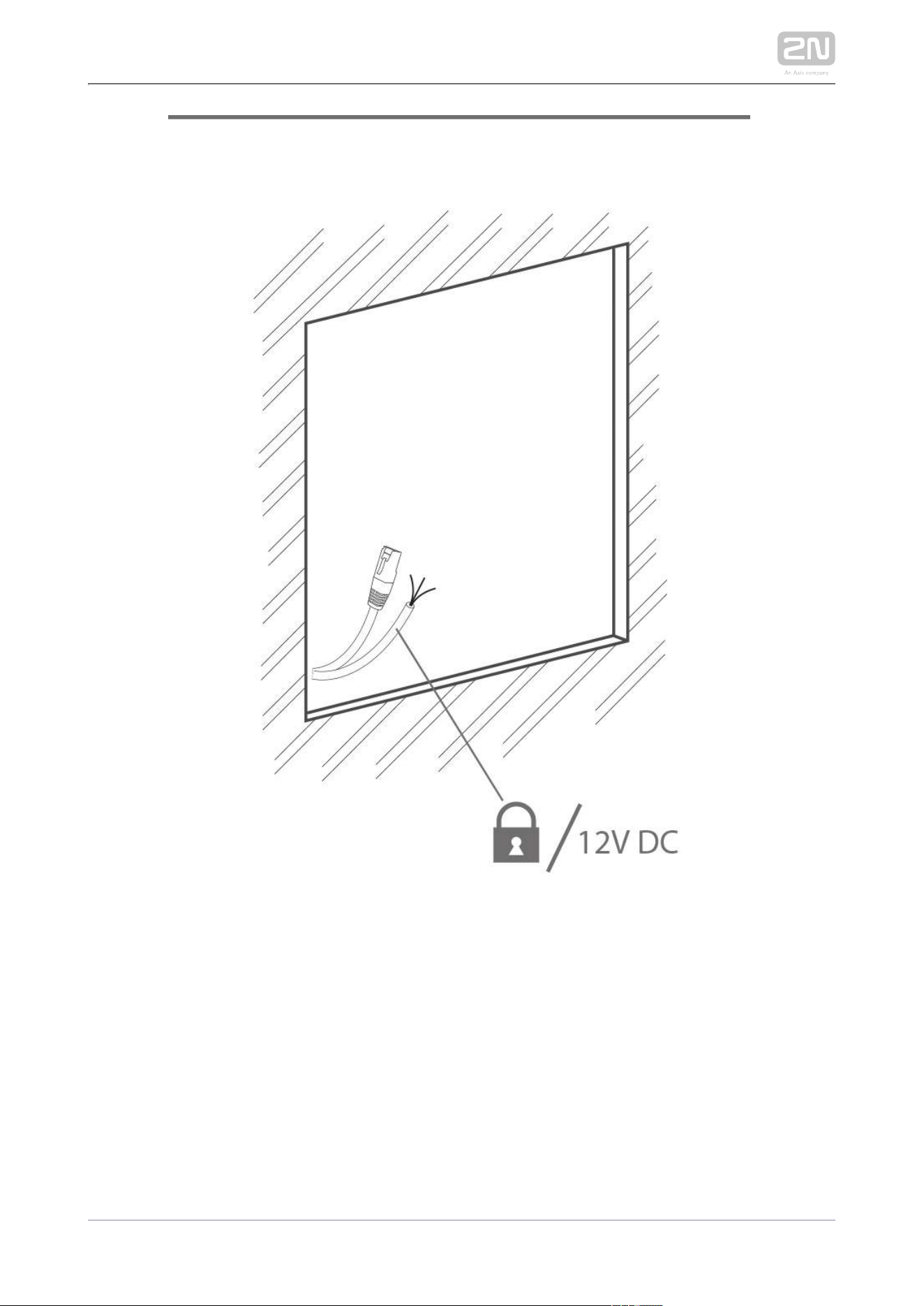
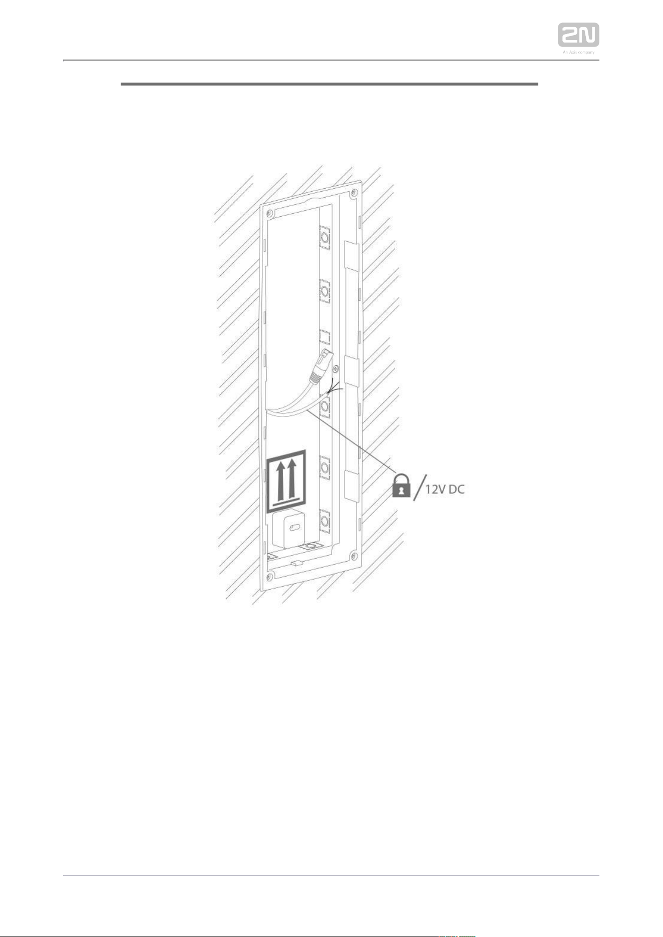
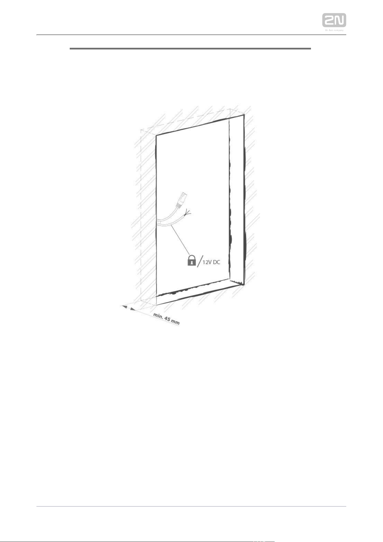
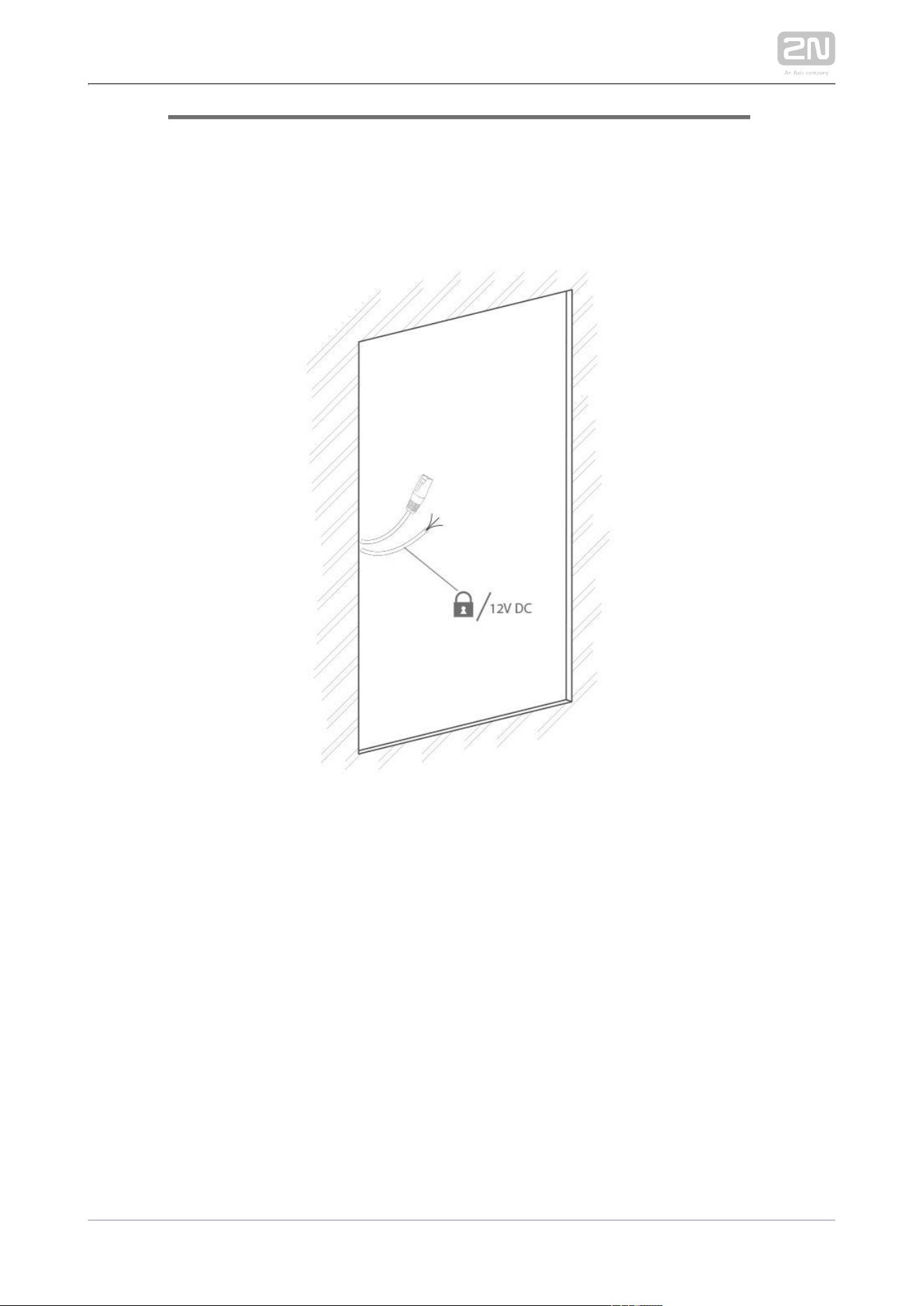
Power Supply Connection
2N IP Verso
®
can be powered either from an external 12 V / 2 A DC source or directly
from the LAN equipped with PoE 802.3af supporting network elements. Owing to
different power outputs, the power supply selection affects the maximum count and
applicability of the modules connected of the main unit.
External power supply
Use a 12 V ±15 % SELV supply dimensioned to the minimum current consumption of 2
A (Part No. 91341481E) to make your system work reliably. This power supply provides
with 24 W for feeding of the main unit and connected modules.2N IP Verso
®
PoE Power Supply
2N IP Verso
®
is compatible with the PoE 802.3af (Class 0–12,95 W) technology and
can be fed directly from the LAN via the compatible network elements. If your LAN
does not support this technology, insert a PoE injector, Part No. 91378100, between 2N
and the nearest network element. This power supply provides IP Verso
®
2N IP Verso
®
with 12 W for feeding of the main unit and connected modules.
Combined Power Supply
2N IP Verso
®
can be fed from an external power supply and PoE at the same time. In
this configuration, the maximum power for the connected modules is available.
2N TELEKOMUNIKACE a.s., www.2n.cz 252/319
LAN Connection
2N IP Verso
®
is connected to the Local Area Network (LAN) via the UTP/STP cable
(Cat 5e or higher) terminated with an RJ-45 (LAN) connector. As the device is
equipped with the Auto-MDIX function, both the straight and crossed cable can be
used.
Caution
We recommend the use of a LAN surge protection.
We recommend the use of a shielded SSTP Ethernet cable with a
shielded RJ-45 connector connected to the switch (with the grounding
option) via the same shielded connector. This makes the device perfectly
grounded.
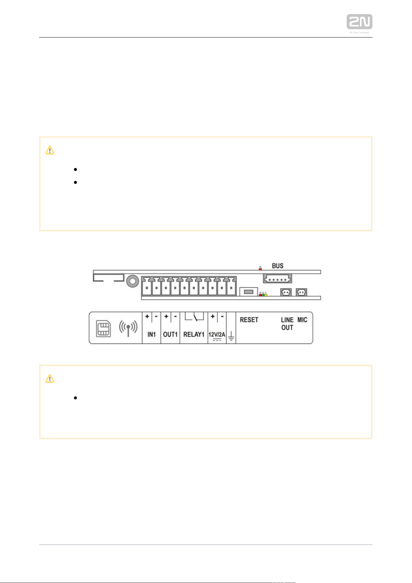
Main Unit Connector Configuration
Caution
We recommend you to use a grounding cable of the cross-section of 1.5
mm .
2

2N TELEKOMUNIKACE a.s., www.2n.cz 253/319
Legend
LAN
(PoE)
LAN (PoE according to 802.1af) connector
IN1 IN1 terminals for input in passive/ active mode (−30 V to +30 V DC)
OFF = open OR U > 1.5 V
IN
ON = closed contact OR U < 1.5 V
IN
OUT1
OUT1 terminals of active input for or electric lock connection 8 up 2N Security Relay
®
to 12 V DC depending on power supply (PoE: 10 V; adaptor: power supply voltage
minus 2 V), max 400 mA
RELAY1 RELAY1 terminals with accessible 30 V / 1 A AC/DC NO/NC contact
12V/2A External 12 V / 2 A DC supply terminals
GND Grounding terminal
RESET RESET / FACTORY RESET button
RGY LED indicators (red/green/yellow)
LINE
OUT
LINE OUT connector (1 V ). Connector type JST SHR-02V-S.
RMS
MIC MIC connector for microphone connection
BUS
2N IP Verso
®
bus connector
2N TELEKOMUNIKACE a.s., www.2n.cz 254/319
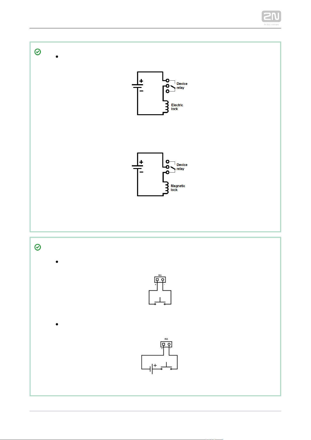
Output wiring diagram for Relay terminals
The electric lock is opened by power supply connection.
The magnetic lock is opened by power supply disconnection.
Tip
Wiring Diagram of IN1 connector in active mod
Wiring Diagram of IN1 connector in passive mod
2N TELEKOMUNIKACE a.s., www.2n.cz 255/319
Reset Button
Located among the main unit connectors, the Reset button helps you reset the factory
default values, restart the device, find the device IP address and switch the static
/dynamic mode.
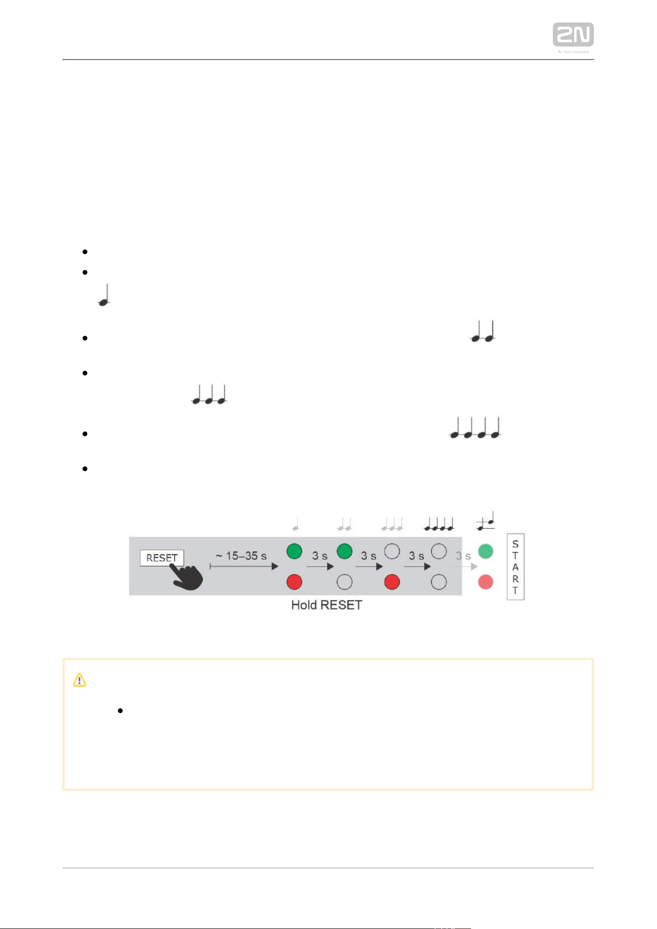
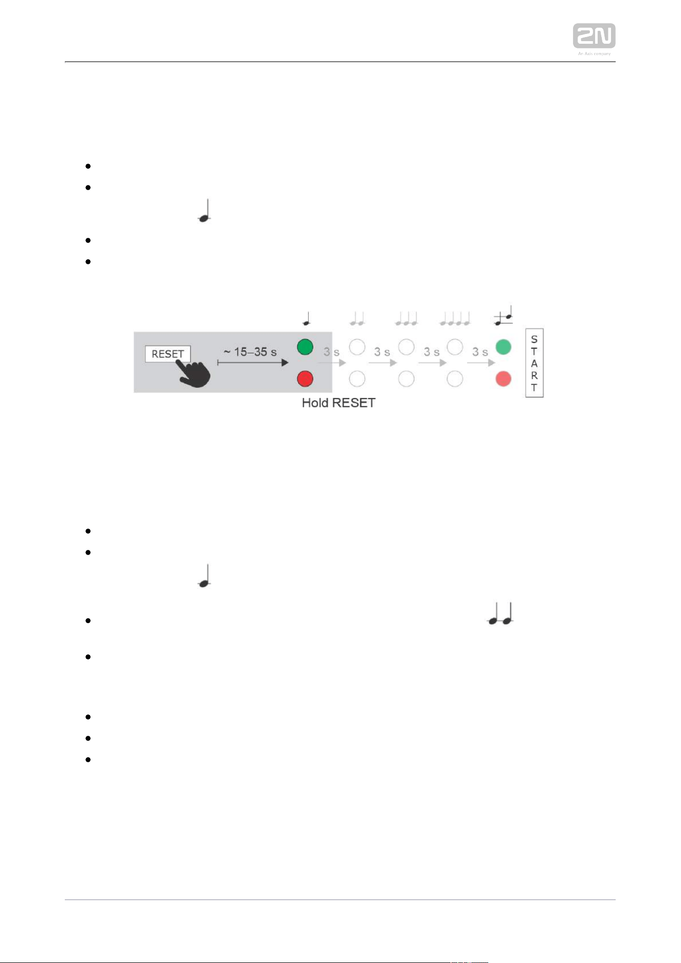
Factory Reset
Follow the instructions below to :reset the factory default values
Press and hold the RESET button.
Wait until the red and green LEDs go on simultaneously and the acoustic signal
can be heard (approx. 15–35 s).
Wait until the red LED goes off and the acoustic signal can be heard
(approx. for another 3 s).
Wait until the green LED goes off and the red LED goes on again and the
acoustic signal can be heard (approx. for another 3 s).
Wait until the red LED goes off and the acoustic signal can be heard
(approx. for another 3 s).
Release the RESET button.
Caution
In case of resetting the factory default settings on a device with a
version of firmware 2.18 or higher it is necessary to reprogram the
using the instructions from section .2N Security Relay
®
2.4
2N TELEKOMUNIKACE a.s., www.2n.cz 256/319
IP Address Finding
Follow the instructions below to :identify the current IP address
Press and hold the RESET button.
Wait until the red and green LEDs go on simultaneously on the device and the
acoustic signal can be heard (approx. 15–35 s).
Release the RESET button.
The device automatically announces the current IP address.
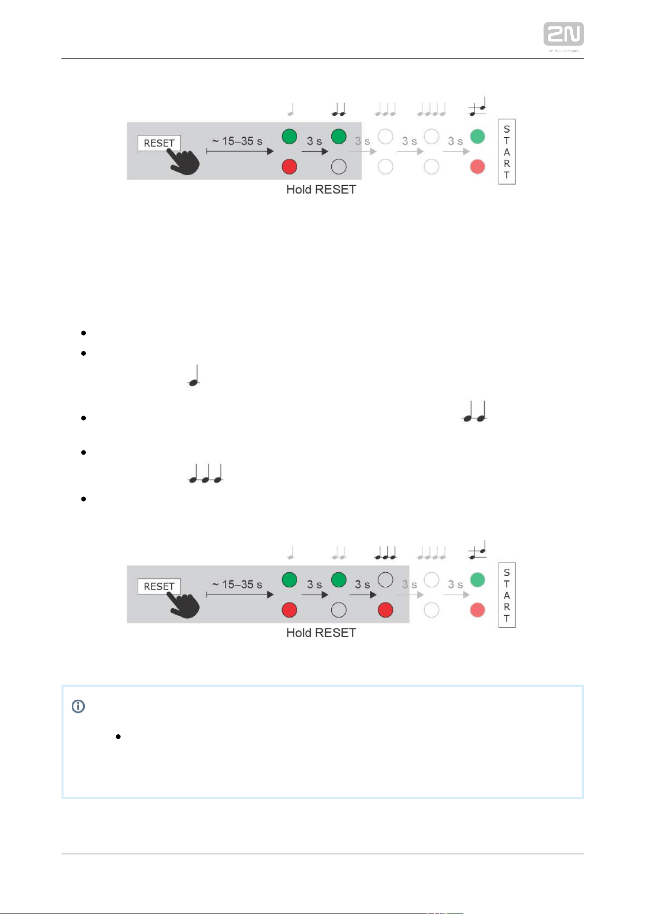
Static IP Address Setting
Foll ow the instructions below to switch on the mode (DHCP OFF):Static IP address
Press and hold the RESET button.
Wait until the red and green LEDs go on simultaneously on the device and the
acoustic signal can be heard (approx. 15–35 s).
Wait until the red LED goes off and the acoustic signal can be heard
(approx. for another 3 s).
Release the RESET button.
The following network parameters will be set after restart:
IP address: 192.168.1.100
Network mask: 255.255.255.0
Default gateway: 192.168.1.1
2N TELEKOMUNIKACE a.s., www.2n.cz 257/319
Dynamic IP Address Setting
Follow the instructions below to switch on the mode (DCHP ON):Dynamic IP address
Press and hold the RESET button.
Wait until the red and green LEDs go on simultaneously on the device and the
acoustic signal can be heard (approx. 15–35 s).
Wait until the red LED goes off and the acoustic signal can be heard
(approx. for another 3 s).
Wait until the green LED goes off and the red LED goes on again and the
acoustic signal can be heard (approx. for another 3 s).
Release the RESET button.
Note
The delay after pressing RESET till the first light and sound signalling is
set to 15–35 s depending on the 2N IP intercom/answering unit model
used.
Device Restart

2N TELEKOMUNIKACE a.s., www.2n.cz 258/319
Device Restart
Press the RESET button shortly (< 1 s) to restart the system without changing
configuration.
Available Switches
Location Name Description
Main Unit Relay 1 Passive switch: NO/NC contact, up to 30 V / 1 A AC/DC
Output
1
Active switch output: 8 up to 12 V DC depending on power supply (PoE: 10
V; adaptor: power supply voltage minus 2 V), max 400 mA
I/O
Module*
(Part No.
9155034)
ext.
relay1
Passive relay switch: NO and NC contacts, up to 30 V / 1 A AC/DC
ext.
relay2
Passive relay switch: NO and NC contacts, up to 30 V / 1 A AC/DC
More modules marked by * can be used.
2N TELEKOMUNIKACE a.s., www.2n.cz 259/319
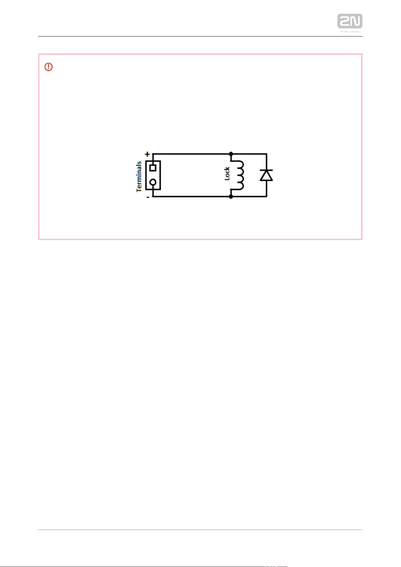
Warning
When you connect a device containing a coil, such as a relay or an
electromagnetic lock, it is necessary to protect the intercom against voltage
peak while switching off the induction load. For this way of protection we
recommend a diode 1 A / 1000 V (e.g., 1N4007, 1N5407, 1N5408) connected
antiparallel to the device.
2N TELEKOMUNIKACE a.s., www.2n.cz 260/319
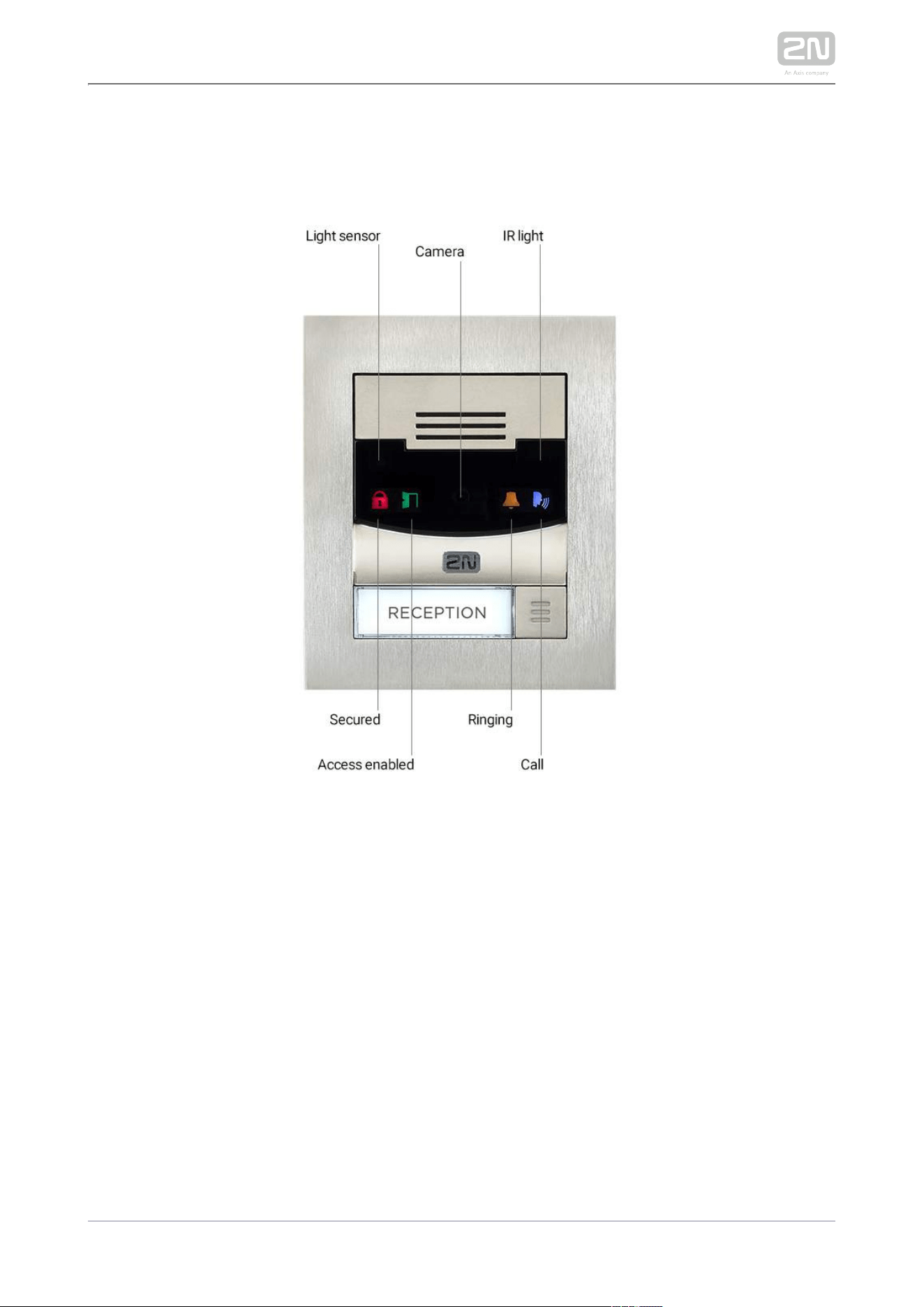
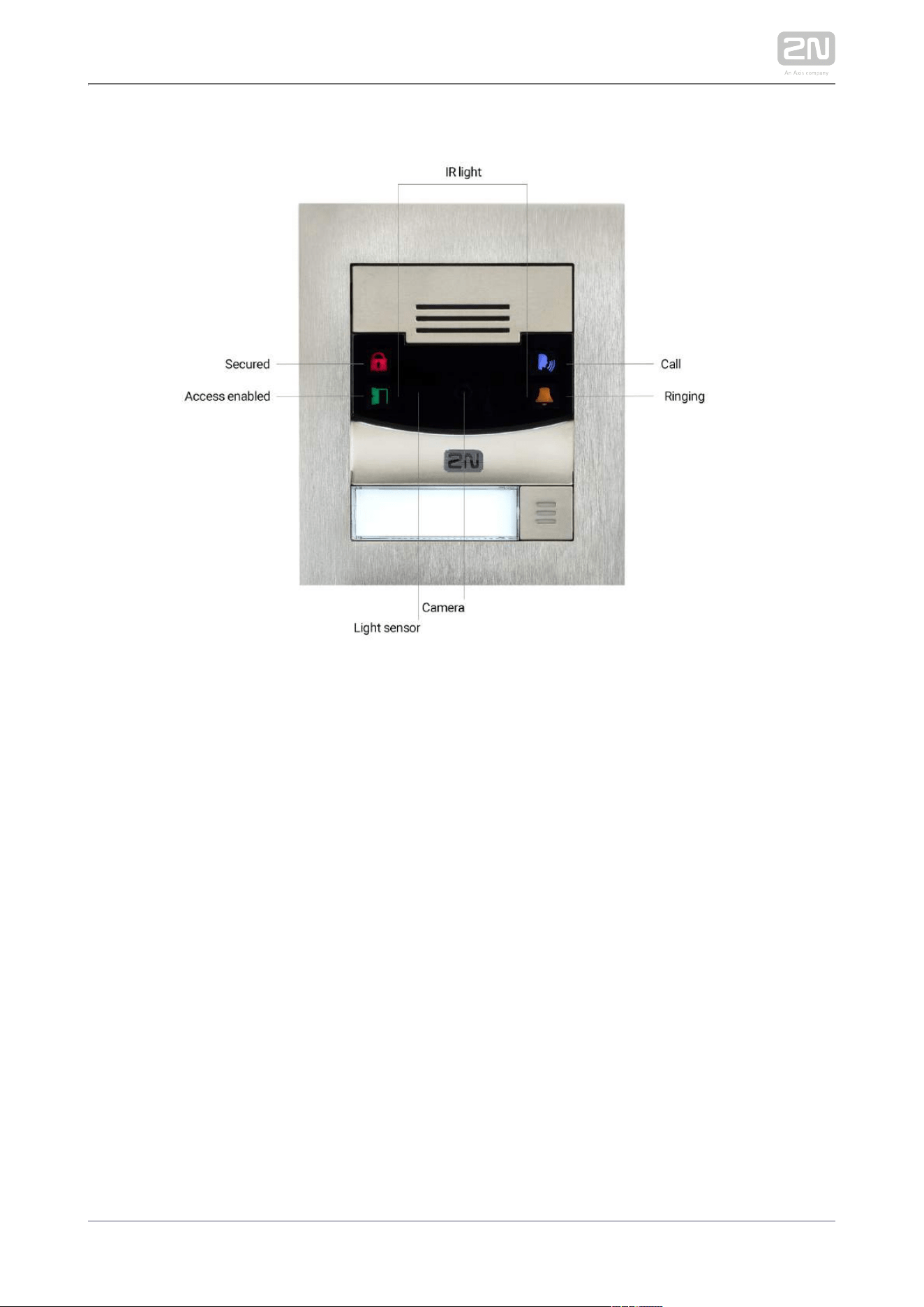
Main Unit LED Pictograms
HW version 4 and higher
2N TELEKOMUNIKACE a.s., www.2n.cz 261/319
HW version 3 and lower

2N TELEKOMUNIKACE a.s., www.2n.cz 262/319
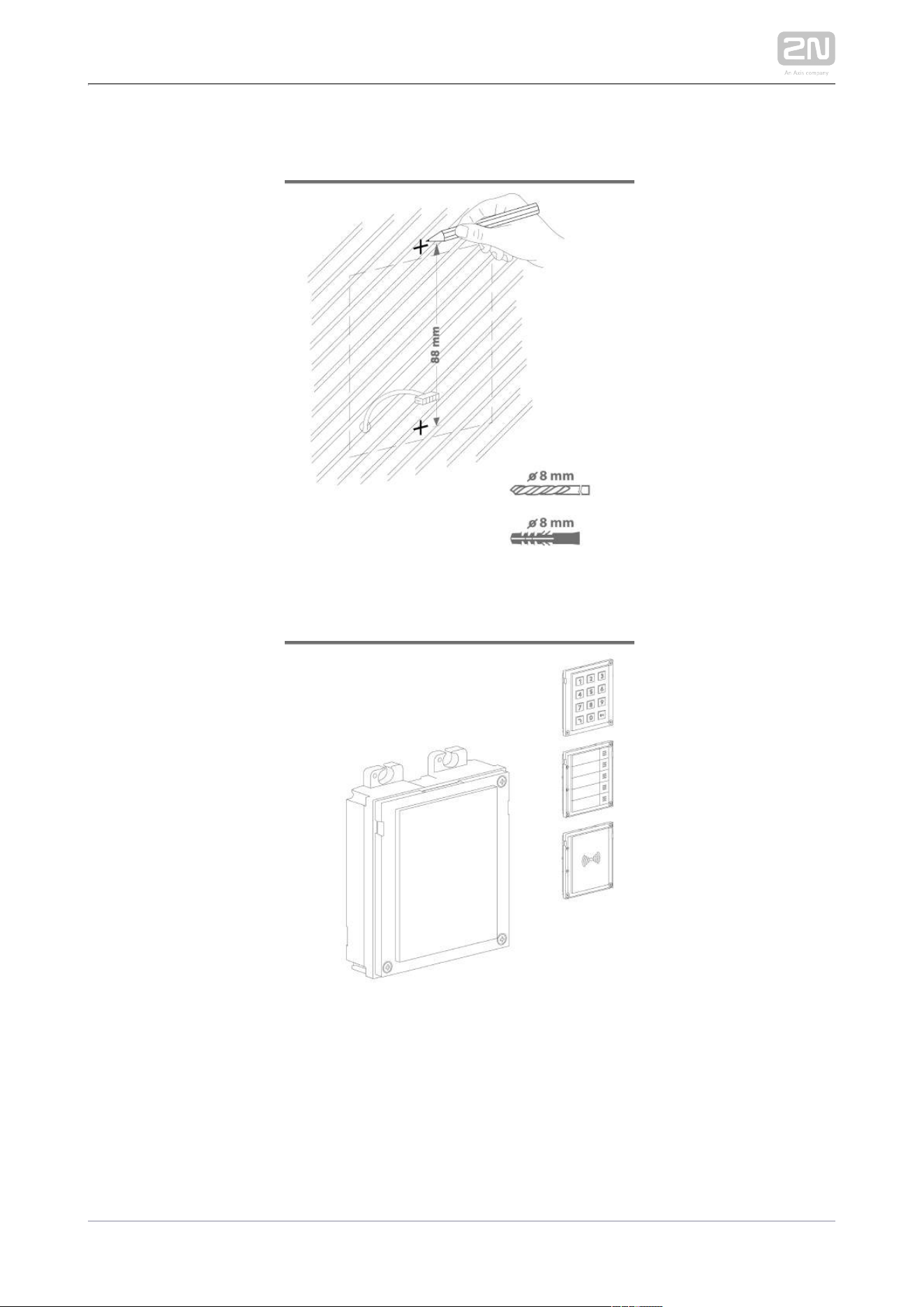
2.4 Extending Module Connection
2N IP Verso
®
allows you to connect the following extending modules:
Infopanel
Keypad
Touch Keypad
RFID Card Reader 125 kHz
RFID Card Reader 13.56 MHz NFC Support
Secured RFID Card Reader 13.56 MHz NFC Support
Bluetooth & RFID reader 125kHz, 13.56MHz, NFC
Bluetooth & RFID reader 125kHz, secured 13.56MHz, NFC
Touch keypad & RFID reader 125kHz, 13.56MHz, NFC
Touch keypad & RFID reader 125kHz, secured 13.56MHz, NFC
Bluetooth Reader
Touch Display
Induction Loop
Fingerprint Reader
I/O Module
5-Button
Wiegand Module
Tamper Switch
Blind Panel
Security Relay
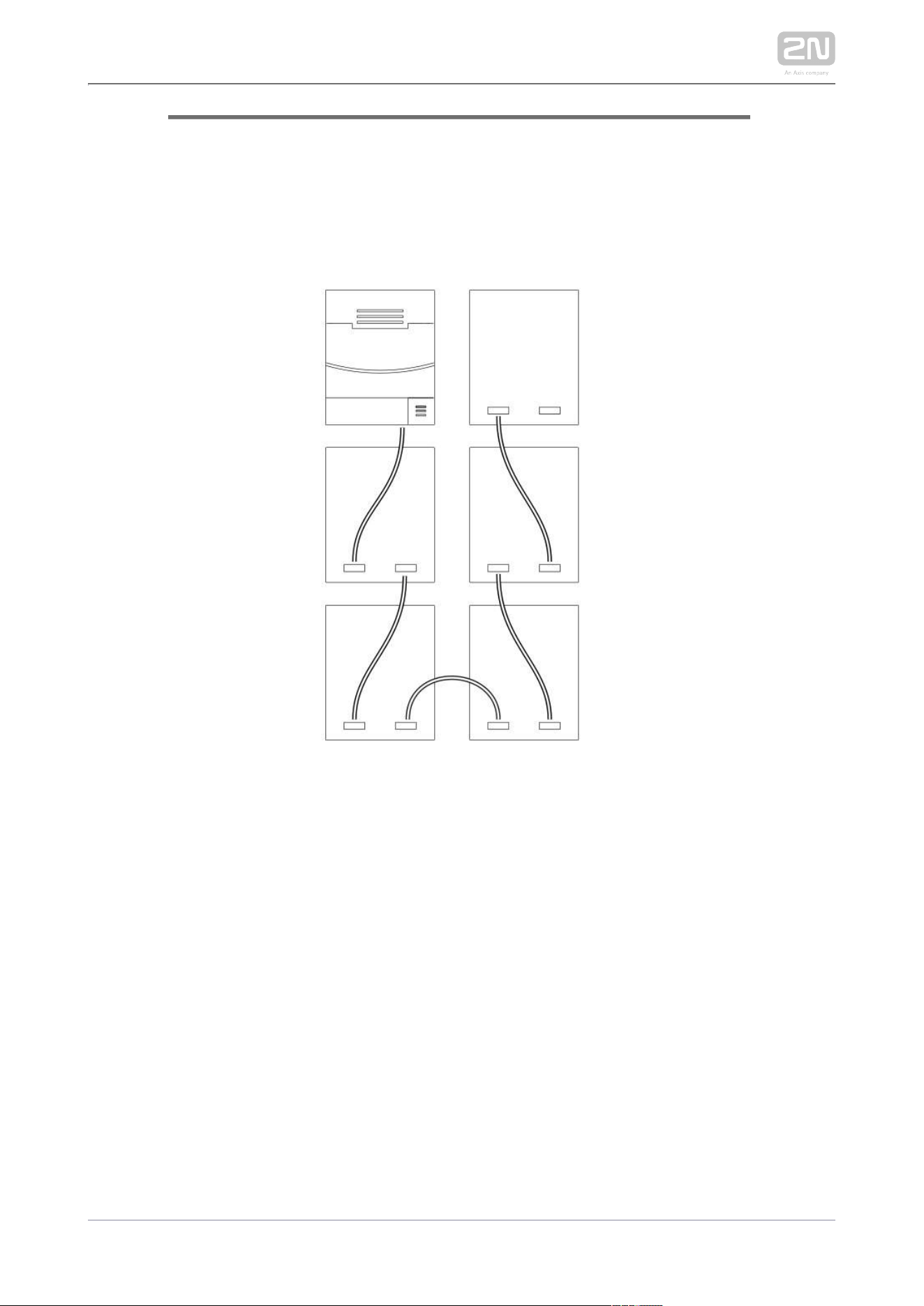
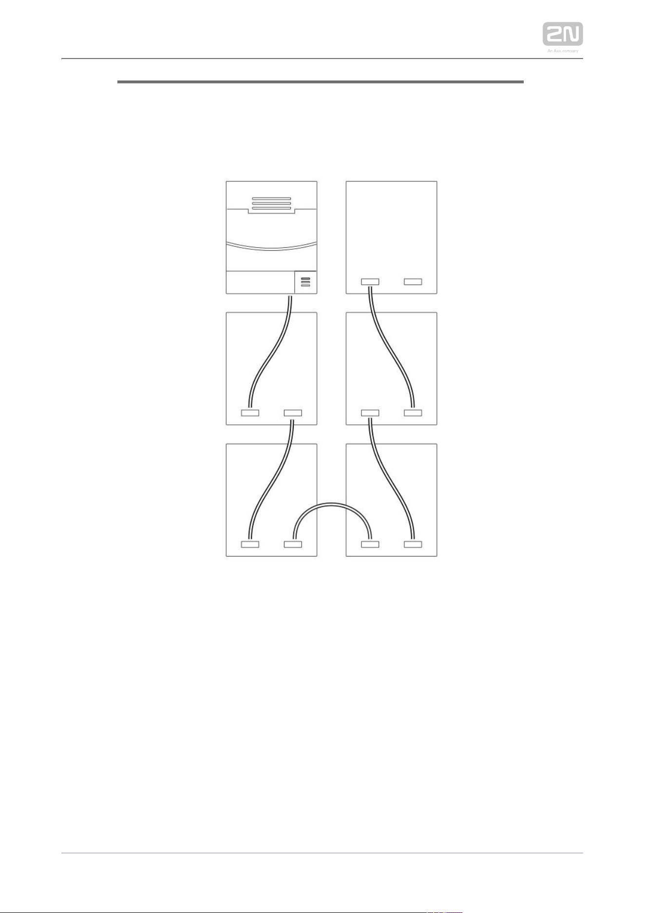
Module Bus Interconnection
All the modules, except for the Tamper Switch, are interconnected via a 2N
®
IP Verso
bus. The bus starts on the main unit and goes over all the modules. The order of
modules on the bus is irrelevant. And it also irrelevant which bus connector on the
module is used as the input and which is used as the output.
The modules include a 220 mm long interconnecting cable; the Wiegand (9155037)
and I/O modules (9155034) include an 80 mm long interconnecting cable.
You can order a separate 1 m long bus cable (9155050) for remote installation of the
modules. Typically, it helps install an RFID card reader on the opposite 2N
®
IP Verso
side of the wall on which the intercom is installed.2N
®
IP Verso

2N TELEKOMUNIKACE a.s., www.2n.cz 263/319
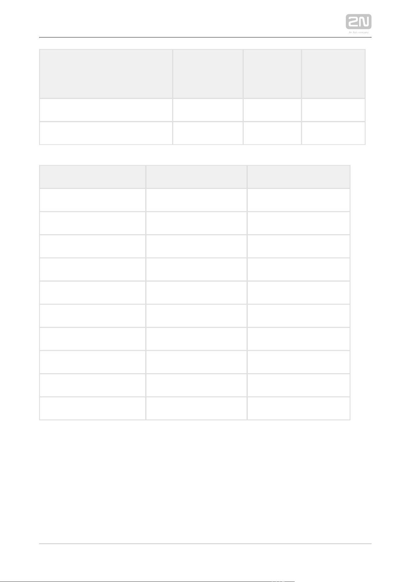
The modules can be combined in each base as follows:
Module Externally
mounted (visible
module)
Internally
mounted (invisible
module)
Internally mounted
on bottom base
edge
Infopanel X
Keypad X
Touch keypad X
RFID card reader 125 kHz X
RFID card reader 13.56 MHz X
RFID card reader 13.56 MHz
NFC support
X
Secured RFID card reader 13.56
MHz NFC
X
Bluetooth & RFID reader
125kHz, 13.56MHz, NFC
X
Bluetooth & RFID reader
125kHz, secured 13.56MHz, NFC
X
Touch keypad & RFID reader
125kHz, 13.56MHz, NFC
X
Touch keypad & RFID reader
125kHz, secured 13.56MHz, NFC
X
Bluetooth reader
X
2N TELEKOMUNIKACE a.s., www.2n.cz 264/319
Module Externally
mounted (visible
module)
Internally
mounted (invisible
module)
Internally mounted
on bottom base
edge
Touch display X
Induction loop X
Fingerprint reader X
I/O module X
5-button X
Wiegand X
Tamper switch X
Blind X
Security Relay X
Module Power Supply
Except for the protection switch module, all the modules are powered 2N
®
IP Verso
from the bus. The available bus power output depends on the power supply type.
Main units 571v3 and higher can use a 3A power supply to increase the bus power
available for the modules connected.
Power supply Specification Available power
External supply 12 V ±15% / 2 A (3 A) 24 W (36 W)
PoE 802.3af (Class 0–12.95 W) 12 W
Combined External supply + PoE 30 W (42 W)
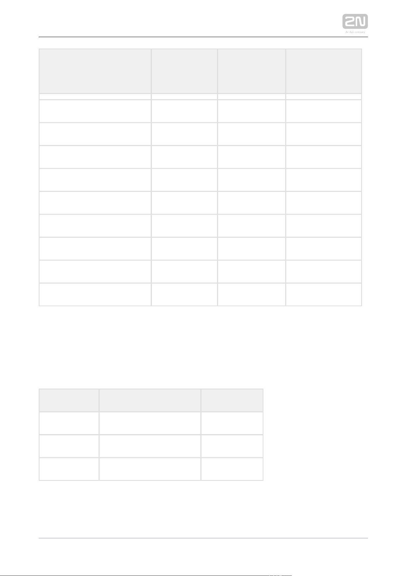
The count of modules on the bus is limited by the available power supply output. The
maximum count of the modules on the bus is 30.
2N TELEKOMUNIKACE a.s., www.2n.cz 265/319
Main unit
(571v3)
Consumption [W]
(Maximum value)
At relax 2.376
Infrared illumination 3.06
LED – call 0.072
LED – ringing 0.072
LED – lock 0.072
LED – secured 0.096
Button backlight 0.072
Name tag backlight 0.072
Unit backlight 0.072
Relay 1 0.132
OUT 1 4.8
Audio 2.94
Total 13.84
Module Idle consumption
[W]
(Minimum value)
Full load [ ]W
(Maximum
value)
Special elements
[ ]W
Main unit with camera 2.36 11.57
Main unit without camera 2.12 11.57
Infopanel 0.17 0.35

2N TELEKOMUNIKACE a.s., www.2n.cz 266/319
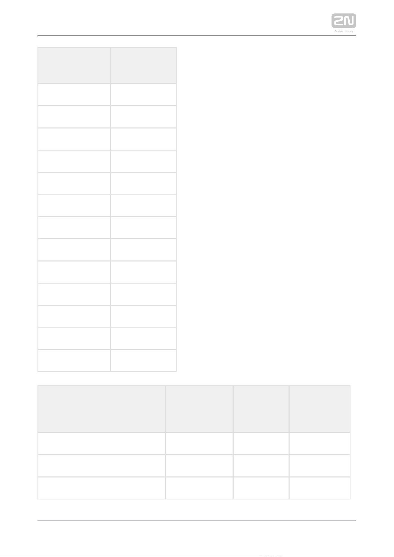
Module Idle consumption
[W]
(Minimum value)
Full load [ ]W
(Maximum
value)
Special elements
[ ]W
Keypad 0.19 1.16
RFID card reader 125 kHz 0.52 1.31
RFID card reader 13.56 MHz 0.44 0.82
RFID card reader 13.56 MHz NFC 0.44 0.82
Secured RFID card reader 13.56 MHz
NFC
0.44 0.82
Bluetooth & RFID reader 125kHz, 13.56
MHz, NFC
1.34 2.74
Bluetooth & RFID reader 125kHz,
secured 13.56MHz, NFC
1.34 2.74
Touch keypad & RFID reader 125kHz,
13.56MHz, NFC
1.38 2.52
Touch keypad & RFID reader 125kHz,
secured 13.56MHz, NFC
1.38 2.52
Bluetooth reader 0.20 0.67
Touch display 0.19 1.70
Induction loop 0.18 0.84
Fingerprint reader 0.73 1.54
I/O 0.31 0.65 Closed relay 0.13
5-button 0.19 1.16
Wiegand 0.46 0.46
2N TELEKOMUNIKACE a.s., www.2n.cz 267/319
Module Idle consumption
[W]
(Minimum value)
Full load [ ]W
(Maximum
value)
Special elements
[ ]W
Tamper switch 0.31 0.65
Blind panel x x
Specimen configuration consumption computation
Module Minimum consumption [W] Maximum consumption [W]
Main unit with camera 2.36 11.57
RFID card reader 13.56 MHz 0.44 0.82
I/O 0.31 0.65
5-button 0.19 1.16
Touch display 1.16 2.02
I/O 0.31 0.65
Tamper switch 0.31 0.65
Wiegand 0.46 0.46
Bluetooth reader 0.20 0.67
Total 5.74 18.65
It is obvious from the specimen configuration that all the modules have sufficient
outputs when an external power supply is used. When a PoE supply is used, the power
output is insufficient for all the modules, which results in automatic decrease in
backlight level, active output current supply, volume and LED intensity. Some modules
need a specific power output for their specific activities: the I/O module, e.g., requires
0.13 W for relay closing (not calculated for minimum consumption).

2N TELEKOMUNIKACE a.s., www.2n.cz 268/319
Infopanel
The Infopanel ( ) is one of the intercom elements and is Part No. 9155030 2N
®
IP Verso
used for inserting and backlighting printed information.
The module contains two bus connectors.2N
®
IP Verso
These two connectors are fully interchangeable and can be used both as inputs
from the main unit and outputs to other modules.
If this module is the last one on the bus, one of the connectors remains
unconnected.
The module package includes a 220 mm long interconnecting cable.
Nametag dimensions: 69,2 (W) x 86,7 (H) mm (dimensional tolerance: +0; -0,5
mm).
Refer to for printing template.www.2n.cz
Keypad
The Keypad ( ) is one of the intercom elements and Part No. 9155031 2N
®
IP Verso
provides a numerical input in the system.
The module contains two bus connectors. 2N
®
IP Verso
These two connectors are fully interchangeable and can be used both as inputs
from the main unit and outputs to other modules.
If this module is the last one on the bus, one of the connectors remains
unconnected.
The module package includes a 220 mm long interconnecting cable.
Touch Keypad
The Touch keypad ( ) is one of the intercom elements Part No. 9155047 2N
®
IP Verso
and provides a numerical input in the system.
The module contains two bus connectors. 2N
®
IP Verso
These two connectors are fully interchangeable and can be used both as inputs
from the main unit and outputs to other modules.
If this module is the last one on the bus, one of the connectors remains
unconnected.
The module package includes a 220 mm long interconnecting cable.
2N TELEKOMUNIKACE a.s., www.2n.cz 269/319
RFID Card Reader Module 125 kHz
The 125 kHz RFID card reader ( ) is one of the intercom Part No. 9155032 2N
®
IP Verso
elements and is used for reading RFID card Ids in the 125 kHz band.
The module contains two bus connectors.2N
®
IP Verso
These two connectors are fully interchangeable and can be used both as inputs
from the main unit and outputs to other modules.
If this module is the last one on the bus, one of the connectors remains
unconnected.
The module package includes a 220 mm long interconnecting cable.
The following RFID cards can be read:
EM4xxx
Caution
To increase the reader's reading distance in combination with a touch
display in a single installation, we recommend you to pull the M-Bus and
LAN cables through separate bushings to avoid their crossing.

2N TELEKOMUNIKACE a.s., www.2n.cz 270/319
RFID Card Reader 13.56 MHz NFC Support
The 13.56 MHz RFID card reader ( ) is one of the Part No. 9155040 2N
®
IP Verso
intercom elements and is used for reading RFID card Ids in the 13.56 MHz band.
The module contains two bus connectors.2N
®
IP Verso
These two connectors are fully interchangeable and can be used both as inputs
from the main unit and outputs to other modules.
If this module is the last one on the bus, one of the connectors remains
unconnected.
The module package includes a 220 mm long interconnecting cable.
The following RFID cards can be read (only the card serial number is read):
ISO14443A (Mifare, DESFire)
PicoPass (HID iClass)
FeliCa
ST SR(IX)
2N Mobile Key
®

2N TELEKOMUNIKACE a.s., www.2n.cz 271/319
Secured RFID Card Reader 13.56 MHz NFC Support
The Secured RFID card reader 13.56 MHz NFC support ( ) is one of Part No. 9155086
the intercom elements and is used for reading RFID card Ids in the 13.56 2N
®
IP Verso
MHz band.
The module contains two bus connectors.2N
®
IP Verso
These two connectors are fully interchangeable and can be used both as inputs
from the main unit and outputs to other modules.
If this module is the last one on the bus, one of the connectors remains
unconnected.
The module package includes a 220 mm long interconnecting cable.
The following RFID cards can be read (optionally the card serial number or PAC ID is
read):
ISO14443A (Mifare, DESFire)
PicoPass (HID iClass)
FeliCa
ST SR(IX)
2N Mobile Key
®
HID SE (Seos, iClass SE, Mifare SE)
2N TELEKOMUNIKACE a.s., www.2n.cz 272/319
Bluetooth & RFID reader 125kHz, 13.56MHz, NFC
Bluetooth with a combined 125 kHz and 13.56 MHz card reader module (Part No.
) is one of the intercom elements and is used for Smartphone/2N9155082 2N IP Verso
®
Mobile Key tablet/card access control, making user calls and/or other functions.
®
NFC – a licensed function, for 2N Mobile Key for Android only.
®
The module contains two bus connectors.2N IP Verso
®
These two connectors are fully interchangeable and can be used either as inputs
from the basic unit or outputs to other modules.
If this module is the last one on the bus, one of the connectors remains
unconnected.
The module package includes a 220 mm long interconnecting cable.
The following RFID cards can be read:
125 kHz
EM4xxx
13.56 MHz
ISO14443A (Mifare, DESFire)
PicoPass (HID iClass)
FeliCa
ST SR(IX)
2N Mobile Key
®
Tip
To accelerate card reading, you are recommended to select the card
types used by the user in the module settings.
2N TELEKOMUNIKACE a.s., www.2n.cz 273/319
Bluetooth & RFID Reader 125kHz, Secured 13.56MHz, NFC
Bluetooth with a combined 125 kHz and secured 13.56 MHz card reader (Part No.
) is one of the intercom elements and is used for Smartphone/2N9155084 2N IP Verso
®
Mobile Key tablet/card access control, making user calls and/or other functions.
®
NFC – a licensed function, for 2N Mobile Key for Android only.
®
The module contains two bus connectors.2N IP Verso
®
These two connectors are fully interchangeable and can be used either as inputs
from the basic unit or outputs to other modules.
If this module is the last one on the bus, one of the connectors remains
unconnected.
The module package includes a 220 mm long interconnecting cable.
The following RFID cards can be read:
125 kHz
EM4xxx
13.56 MHz
ISO14443A (Mifare, DESFire)
PicoPass (HID iClass)
FeliCa
ST SR(IX)
2N Mobile Key
®
HID SE (Seos, iClass SE, Mifare SE)
Tip
To accelerate card reading, you are recommended to select the card
types used by the user in the module settings.
2N TELEKOMUNIKACE a.s., www.2n.cz 274/319
Touch Keypad & RFID Reader 125kHz, 13.56MHz, NFC
The touch keypad with a combined 125 kHz and 13.56 MHz card reader (Part No.
) is one of the intercom elements and is used for code/card 9155081 2N IP Verso
®
access control, making user calls and/or other functions. The keypad surface is very
sensitive yet weatherproof at the same time.
NFC – a licensed function, for 2N Mobile Key for Android only.
®
The module contains two bus connectors.2N IP Verso
®
These two connectors are fully interchangeable and can be used either as inputs
from the basic unit or outputs to other modules.
If this module is the last one on the bus, one of the connectors remains
unconnected.
The module package includes a 220 mm long interconnecting cable.
The following RFID cards can be read:
125 kHz
EM4xxx
13.56 MHz
ISO14443A (Mifare, DESFire)
PicoPass (HID iClass)
FeliCa
ST SR(IX)
2N Mobile Key
®
Tip
To accelerate card reading, you are recommended to select the card
types used by the user in the module settings.
2N TELEKOMUNIKACE a.s., www.2n.cz 275/319
Touch Keypad & RFID Reader 125kHz, Secured 13.56MHz, NFC
The touch keypad with a combined 125 kHz and secured 13.56 MHz card (Part No.
) reader is one of the intercom elements and is used for code9155083 2N IP Verso
®
/card access control, making user calls and/or other functions. The keypad surface is
very sensitive yet weatherproof at the same time.
NFC – a licensed function, for 2N Mobile Key for Android only.
®
The module contains two bus connectors.2N IP Verso
®
These two connectors are fully interchangeable and can be used either as inputs
from the basic unit or outputs to other modules.
If this module is the last one on the bus, one of the connectors remains
unconnected.
The module package includes a 220 mm long interconnecting cable.
The following RFID cards can be read:
125 kHz
EM4xxx
13.56 MHz
ISO14443A (Mifare, DESFire)
PicoPass (HID iClass)
FeliCa
ST SR(IX)
2N Mobile Key
®
HID SE (Seos, iClass SE, Mifare SE)
Tip
To accelerate card reading, you are recommended to select the card
types used by the user in the module settings.

2N TELEKOMUNIKACE a.s., www.2n.cz 276/319
Bluetooth Reader
The Bluetooth reader ( ) is one of the intercom Part No. 9155046 2N IP Verso
®
elements and helps authenticate and subsequently open doors using Android
and iOS based smartphones via the Bluetooth protocol 4.0 as RFID card
replacement. Install the application from and 2N
®
Mobile Key Google Play
to make authentication work properly. The application requires phones Appstore
with Android OS 4.4 and higher and iOS 9 and higher.
The module contains two bus connectors.2N IP Verso
®
The two connectors are fully interchangeable and can be used both as inputs
from the main unit or outputs to other modules.
If this module is the last one on the bus, one of the connectors remains
unconnected.
The package includes a 220 mm long interconnecting cable.
The module uses the 2.4 GHz frequency.
IDs from the following smart phones can be read:
Android 4.4 and higher
iPhone 4S with iOS 8 and higher and higher
Touch Display
The ( ) module is designed for the Touch display Part No. 9155036 2N IP Verso
®
communicator. This module can be used as:
Infopanel module – displays user defined image sequences
Keypad module – virtual touch keypad
Button module – virtual phone directory
Module connection options:
The module contains two bus connectors.2N IP Verso
®
These two connectors are fully interchangeable and can be used both as inputs
from the basic unit and outputs to other modules.
If this module is the last one on the bus, one of the connectors remains
unconnected.
The module package includes a 220 mm long interconnecting cable.

2N TELEKOMUNIKACE a.s., www.2n.cz 277/319
Technical specification:
Resolution: 320 px x 214 px H x V
Resolution slideshow: 214 px x 214 px
Contrast ratio: 400
Brightness: 350 cd/m2
Weight: 280 g
Working temperature: -20 °C – 60 °C
Resistance level: IK07
Induction Loop
The ( ) is one of the intercom elements Induction loop Part No. 9155041 2N IP Verso
®
and is used to transmit an audio signal directly into a hearing aid via a magnetic field.
The module contains two bus connectors.2N IP Verso
®
These two connectors are fully interchangeable and can be used both as inputs
from the main unit and outputs to other modules.
If this module is the last one on the bus, one of the connectors remains
unconnected.
The module package includes a 220 mm long interconnecting cable.
Used mode: Telecoil (also referred to as t-switch or t-coil)
Maximum power: 2W
Frequency range: 100 Hz – 5 kHz / ± 3 dB
External antenna can be connected – Part No. 9155043
Short circuit resistance: without limitation
2N TELEKOMUNIKACE a.s., www.2n.cz 278/319
Fingerprint Reader
The is one of the intercom Fingerprint reader ( Part No. 9155045 ) 2N IP Verso
®
modules and is used for automated verification of human fingers for access control
and intercom control.
The module contains two bus connectors.2N IP Verso
®
These two connectors are fully interchangeable and can be used both as inputs
from the main unit and outputs to other modules.
If this module is the last one on the bus, one of the connectors remains
unconnected.
The module package includes a 220 mm long interconnecting cable.
Important module properties:
FBI PIV and Mobile ID certification – FAP20
Durable glass touch surface
Rejects spoof fingerprints
-20 to 55 ºC operating temperature range,
0–90% relative humidity, noncondensing
Note
A higher moisture may deteriorate finger papillary line scanning. You are
advised to dry your finger and the reader scanning surface for successful
authentication.
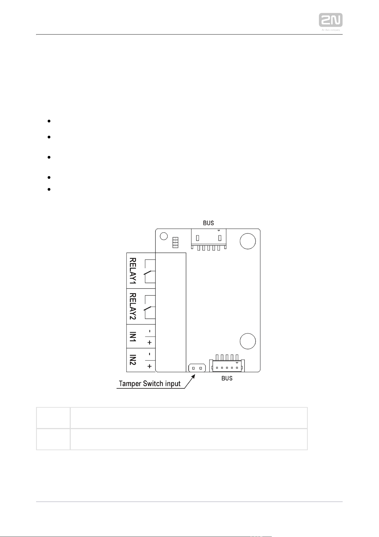
2N TELEKOMUNIKACE a.s., www.2n.cz 279/319
I/O
The I/O ( ) is one of the intercom elements and is used Part No. 9155034 2N IP Verso
®
for extending the number of inputs and outputs.
The module contains two bus connectors.2N
®
IP Verso
These two connectors are fully interchangeable and can be used both as inputs
from the main unit and outputs to other modules.
If this module is the last one on the bus, one of the connectors remains
unconnected.
The module package includes an 80 mm long interconnecting cable.
The inputs / outputs are addressed as follows: <module_name>.<input
, e.g. module5.relay1. The module name is configured in the /output_name>
Module name parameter in the Hardware / Extenders menu.
RELAY1 RELAY1 terminals with accessible 30 V / 1 A AC/DC NO/NC contact
RELAY2
RELAY2 terminals with accessible 30 V / 1 A AC/DC NO/NC contact
2N TELEKOMUNIKACE a.s., www.2n.cz 280/319
IN1 IN1 terminals for input in passive/ active mode (−30 V to +30 V DC)
OFF = open OR U > 1.5 V
IN
ON = closed contact OR U < 1.5 V
IN
IN2 IN2 terminals for input in passive/active mode (−30 V to +30 V DC)
OFF = open OR U > 1.5 V
IN
ON = closed contact OR U < 1.5 V
IN
TAMPER Tamper switch (9155038) input
5-Button
The 5-button ( ) is one of the intercom elements and is Part No. 9155035 2N
®
IP Verso
used for extending the number of buttons.
The module contains two bus connectors.2N IP Verso
®
These two connectors are fully interchangeable and can be used both as inputs
from the main unit and outputs to other modules.
If this module is the last one on the bus, one of the connectors remains
unconnected.
The module package includes a 220 mm long interconnecting cable.
Nametag dimensions:
1 button: 52,0 (W) x 15.2 (H) mm (dimensional tolerance: +0; -0.5 mm).
5 buttons: 57.5 (W) x 89.0 (H) mm (dimensional tolerance: +0; -0.5 mm).
Refer to for nametag printing template.www.2n.cz

2N TELEKOMUNIKACE a.s., www.2n.cz 281/319
Wiegand
The Wiegand ( ) is one of the intercom elements and is Part No. 9155037 2N IP Verso
®
used for connecting an external Wiegand device (RFID card reader, fingerprint or
other biometric data reader) and/or connecting the system to an 2N
®
IP Verso
external security exchange. All the inputs and outputs are galvanically isolated from
the system with insulation strength of 500 V DC. It is necessary to feed 2N IP Verso
®
+U IN on Wiegand OUT from the Control Panel.
Reader – connects an external Wiegand-supporting reader. The reader sends
information on the intercom card number.
Control Panel – used for connection to the security PBX or access system to
which the intercom sends information on the intercom card number.
The module contains two bus connectors.2N IP Verso
®
These two connectors are fully interchangeable and can be used both as inputs
from the main unit and outputs to other modules.
If this module is the last one on the bus, one of the connectors remains
unconnected.
The module package includes an 80 mm long interconnecting cable.
The module name is configured in the Module name parameter in the Hardware /
Extenders menu.
The input LED IN is addressed as follows: , e.g. <module_name>.<input1>
module2.input1.
The input Tamper is addressed as follows: , e.g. <module_name>.<tamper>
module2.tamper.
The output LED OUT (negated) is addressed as follows: <module_name>.
, e.g. module2.output1.<output1>

2N TELEKOMUNIKACE a.s., www.2n.cz 282/319
Reader W0 W1IN,
GNDIN, 1
Isolated 2-wire WIEGAND IN
LED OUT Isolated open LED OUT switched against GND on WIEGAND IN 1
side (up to 24 V / 50 mA)
Control
Panel
+U IN +U (5 to 15 V DC) WIEGAND OUT power supply input
IN
W0 W1 OUT,
GNDOUT, 2
Isolated 2-wire WIEGAND OUT
LED IN
(negated)
Isolated input for open LED IN, input activated by GND2
LED IN Isolated input for open LED IN, input activated by +U
G +U WIEGAND OUT active supply LED indicatorIN
TAMPER Tamper switch (Part No. ) input9155038
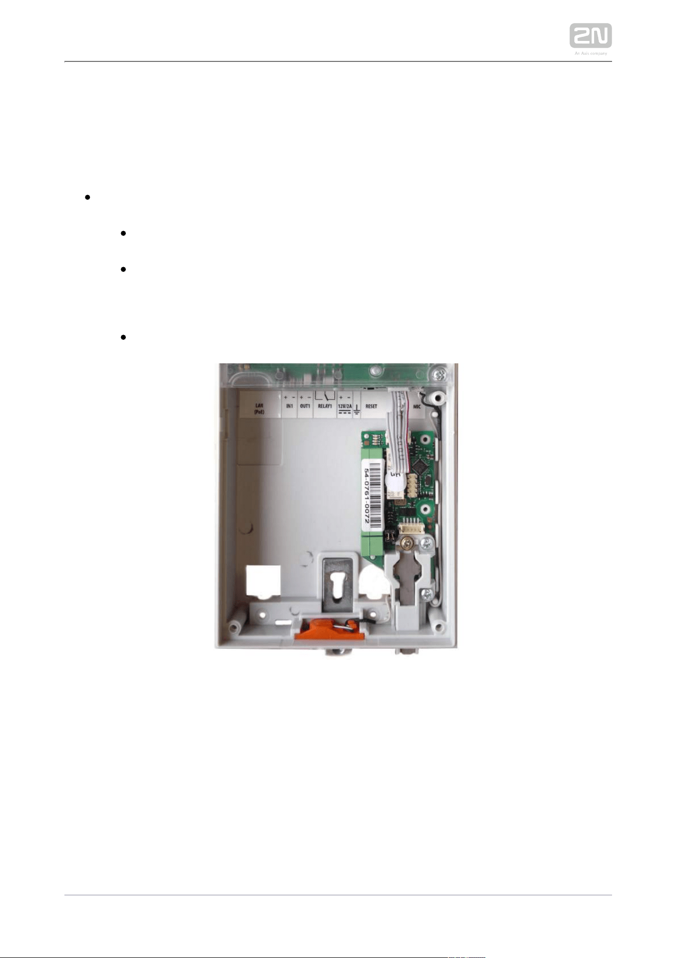
2N TELEKOMUNIKACE a.s., www.2n.cz 283/319
Tamper Switch
The ( ) is one of the intercom elements Tamper switch Part No. 9155038 2N
®
IP Verso
and helps secure the system against tampering.
The module contains two switches that open whenever the front frame is
removed:
One switch leads directly to the terminal board and is designed for
connection to an external security exchange (32 V DC / 50 mA max).
The other switch, together with the or I/O module (9155034) Wiegand
, can be used for alarm signalling via the Automation module (9155037)
interface in the configuration.2N
®
IP Verso
This module is not connected to the bus.
Tamper Switch Mounting
Blind Panel
The ( ) is used to cover an empty position.Blind panel Part No. 9155039
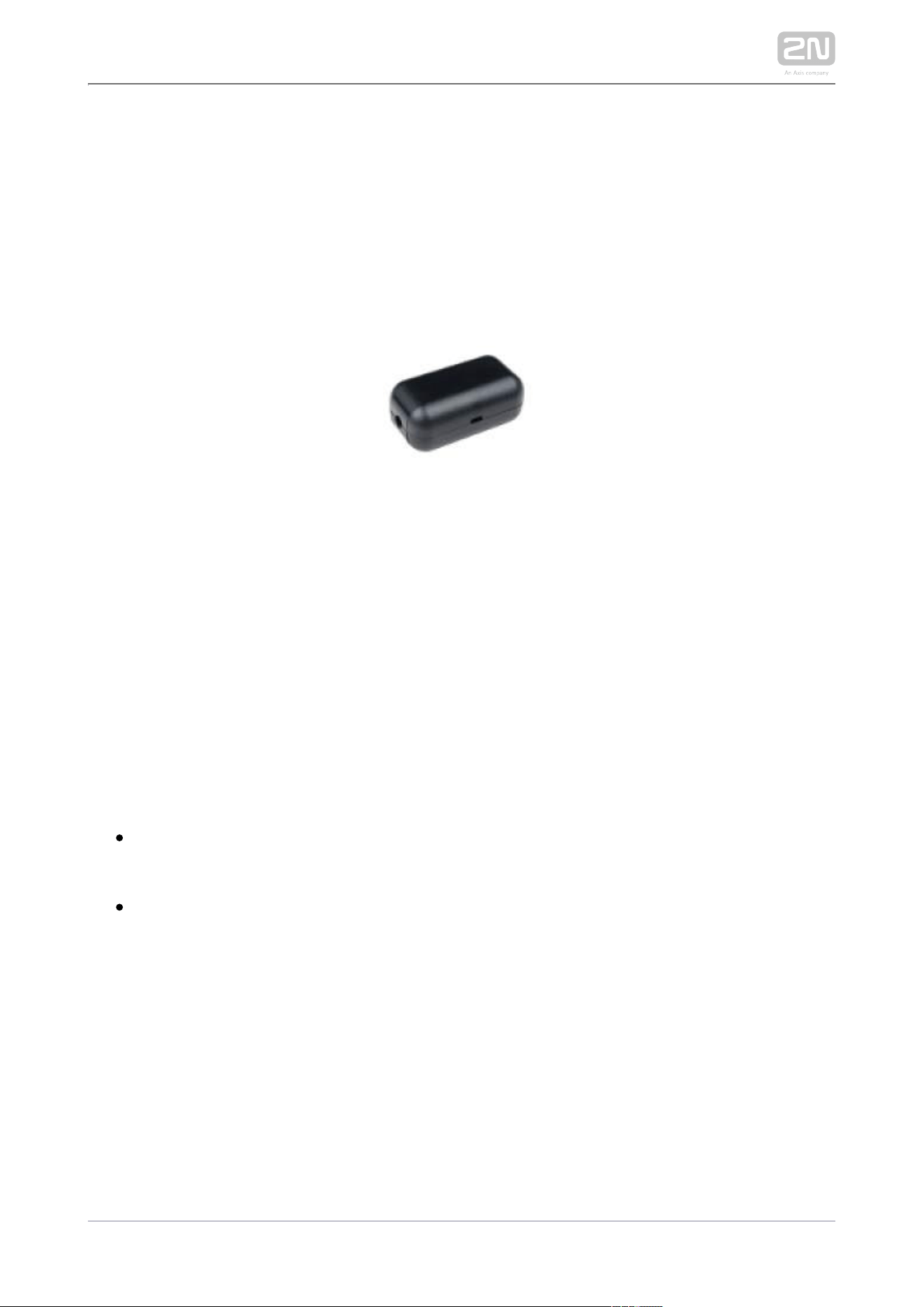
2N TELEKOMUNIKACE a.s., www.2n.cz 284/319
Security Relay
The (Part No. 9159010) is used for enhancing security between the 2N
®
Security Relay
intercom and the connected electric lock. The is designed for any 2N Security Relay
®
model with firmware versions 1.15 and higher. It significantly enhances 2N IP intercom
security of the connected electric lock as it prevents lock opening by forced intercom
tampering.
Function:
The is a device installed between an intercom (outside the 2N Security Relay
®
secured area) and the electric lock (inside the secured area). The 2N Security Relay
®
includes a relay that can only be activated if the valid opening code is received from
the intercom.
Specifications:
Passive switch: NO and NC contacts, up to 30 V / 1 A AC/DC
Switched output:
Where the security relay is fed from the intercom, 9 to 13 V DC is available on
the output depending on the power supply (PoE: 9 V; adapter: source voltage of
minus 1 V) / 400 mA DC.
Where the security relay is fed from an external power supply, 12 V / 700 mA DC
is available on the output.
Dimensions: (56 x 31 x 24) mm
Weight: 20 g
2N TELEKOMUNIKACE a.s., www.2n.cz 285/319
Installation:
Install the onto a two-wire cable between the intercom and the 2N Security Relay
®
electric lock inside the area to be secured (typically behind the door). The device is
powered and controlled via this two-wire cable and so can be added to an existing
installation. Thanks to its compact dimensions, the device can be installed into a
standard mounting box.
Connection:
Connect the to the intercom as follows:2N Security Relay
®
To the intercom active output (OUT1 or OUT2), or
To the intercom relay output with a 12 V DC serial external power supply.
Connect the electric lock to the output as follows:2N Security Relay
®
To the switched output.
To the passive output in series with the external power supply.
The device also supports a Departure button connected between the ‘PB’ and ‘- Helios
IP / intercom’ terminals. Press the Departure button to activate the output for 5
seconds.
Status signalling:
Green LED Red LED Status
flashing off Operational mode
on off Activated output
flashing flashing Programming mode – waiting for initialisation
on flashing Error – wrong code received
2N TELEKOMUNIKACE a.s., www.2n.cz 286/319
Configuration:
Connect the to the properly set intercom switch output; 2N Security Relay
®
refer to the for . Make sure that one LED at Configuration Manual 2N IP intercoms
least on the is on or blinking.2N Security Relay
®
Press and hold the Reset button for 5 seconds to put the 2N Security Relay
®
device in the programming mode (both the red and green LEDs are blinking).
Activate the intercom switch using the keypad, telephone, etc. The first code
sent from the intercom will be stored in the memory and considered valid. After
code initialisation, the will pass into the operational mode 2N Security Relay
®
(the green LED is blinking).
Caution
In case of resetting the factory default settings on a device with a
version of firmware 2.18 or higher it is necessary to reprogram the
using the instructions above.2N Security Relay
®
Tip
FAQ: 2N Security Relay – what is it and how to use it with 2N IP
®
intercom?
Tip
Video Tutorial: Door intercoms 2N Security Relay
®
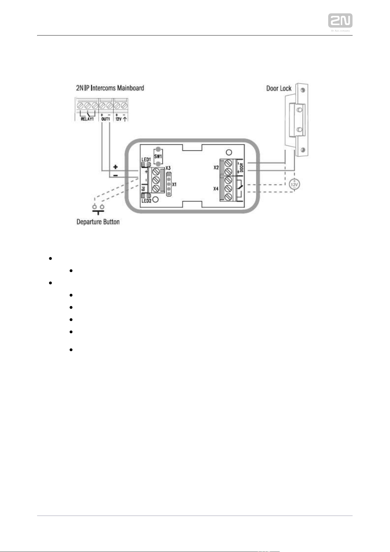
2N TELEKOMUNIKACE a.s., www.2n.cz 287/319
Connection:
125 kHz
EM4xxx
13.56 MHz
ISO14443A (Mifare, DESFire)
PicoPass (HID iClass)
FeliCa
ST SR(IX)
2N Mobile Key
®
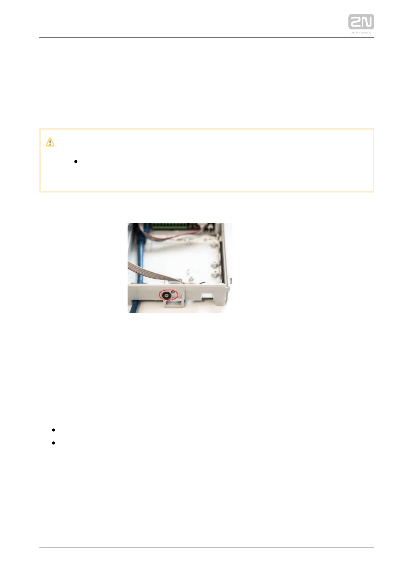
2N TELEKOMUNIKACE a.s., www.2n.cz 288/319
2.5 Completion
Installation Completion
Check the connection of all wires and the RJ-45 plug to the board connector.
Caution
All unused connectors have to have tightened screws in order to avoid
vibration caused by sound.
Make sure before mounting that the black sealing ring is placed properly. We
recommend you to fit the microphone with the screw included in the delivery.
Nametag Placing
Every intercom package includes a piece of transparent foil, which can be laser
printed. Cut the printed foil and insert the nametags in the buttons.
We recommend you to use separate foil for every button in the 5-button module.
Refer to section download for the nametag printing template.
Nametag dimensions for 5-button module:
1 button: 52.0 (W) x 15.2 (H) mm (dimensional tolerance: +0; -0.5 mm)
5 buttons: 57.5 (W) x 89.0 (H) mm (dimensional tolerance: +0; -0.5 mm)
Infopanel nametag dimensions: 69.2 (W) x 86.7 (H) mm (dimensional tolerance: +0;
-0.5 mm).
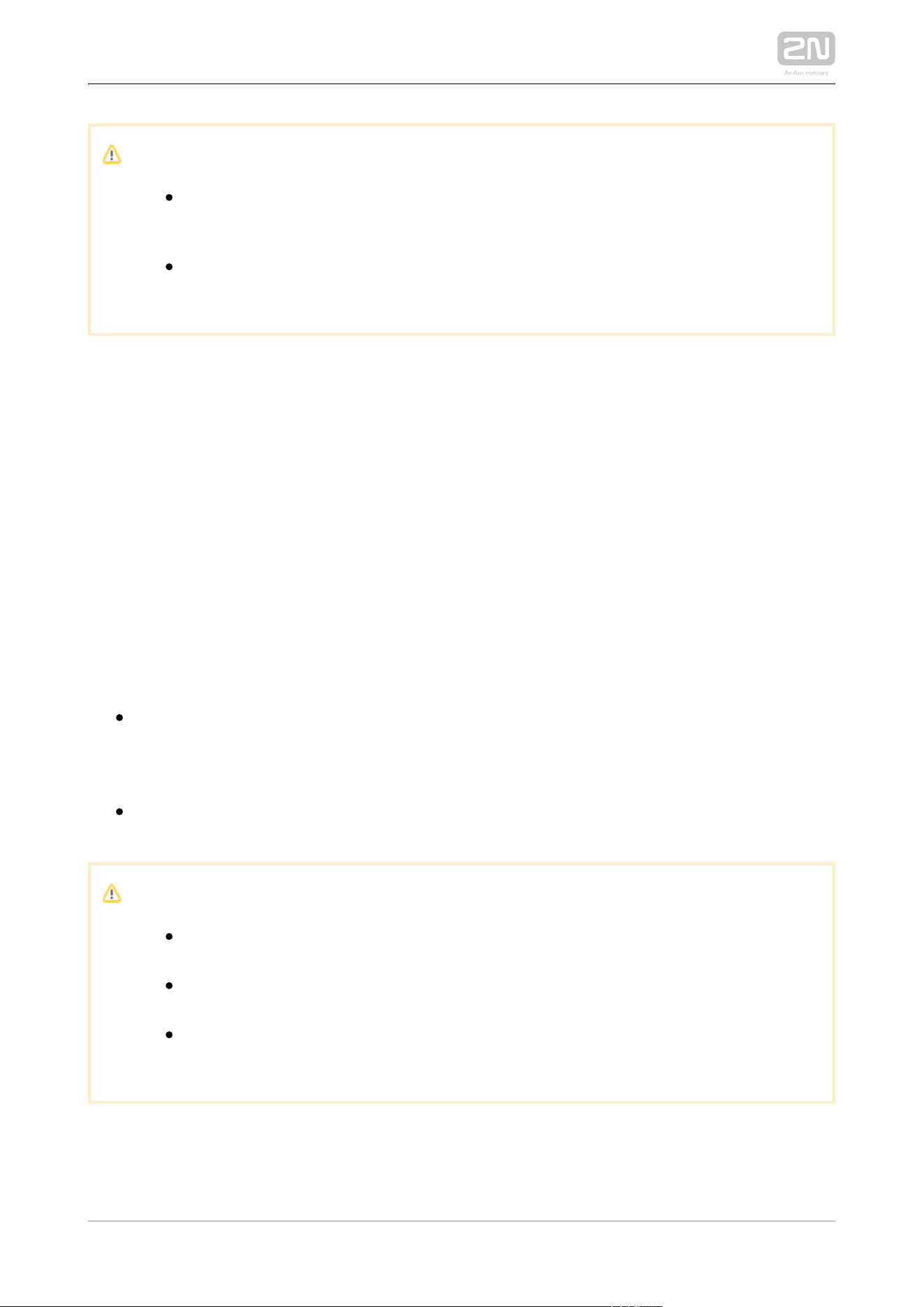
2N TELEKOMUNIKACE a.s., www.2n.cz 289/319
1.
2.
3.
4.
5.
Caution
The area where nametags are placed is called a wet zone. After heavy
rain, water can penetrate to the nametag. Water in this area does not
affect the intercom functionality in any way and evaporates soon.
Always use waterproof foil (enclosed or other) for the nametags. Never
use paper or ink jet printing to avoid damage due to water leakage!
Nametag inserting/replacing:
Remove the frame.
Lift up the button door. The 5-button module buttons have just one door.
Remove the used nametag and insert a new one.
Close the button door.
Replace the frame.
Frame Replacement
Check the frame sealing before replacing the frame.
Version A
Screw the flush mounting frame in the upper and bottom parts.
Version B
Hang the surface mounting frame on the hook in the upper part and then screw
it tight in the bottom part.
Caution
Improper mounting may deteriorate the intercom waterproofness and
water may damage the electronic part.
Make sure that all holes are filled with some waterproof material – the
top part, around the cables and the screws.
Use silicone or some other sealant to seal the box against the wall if
uneven to avoid water leakage and wall damping..
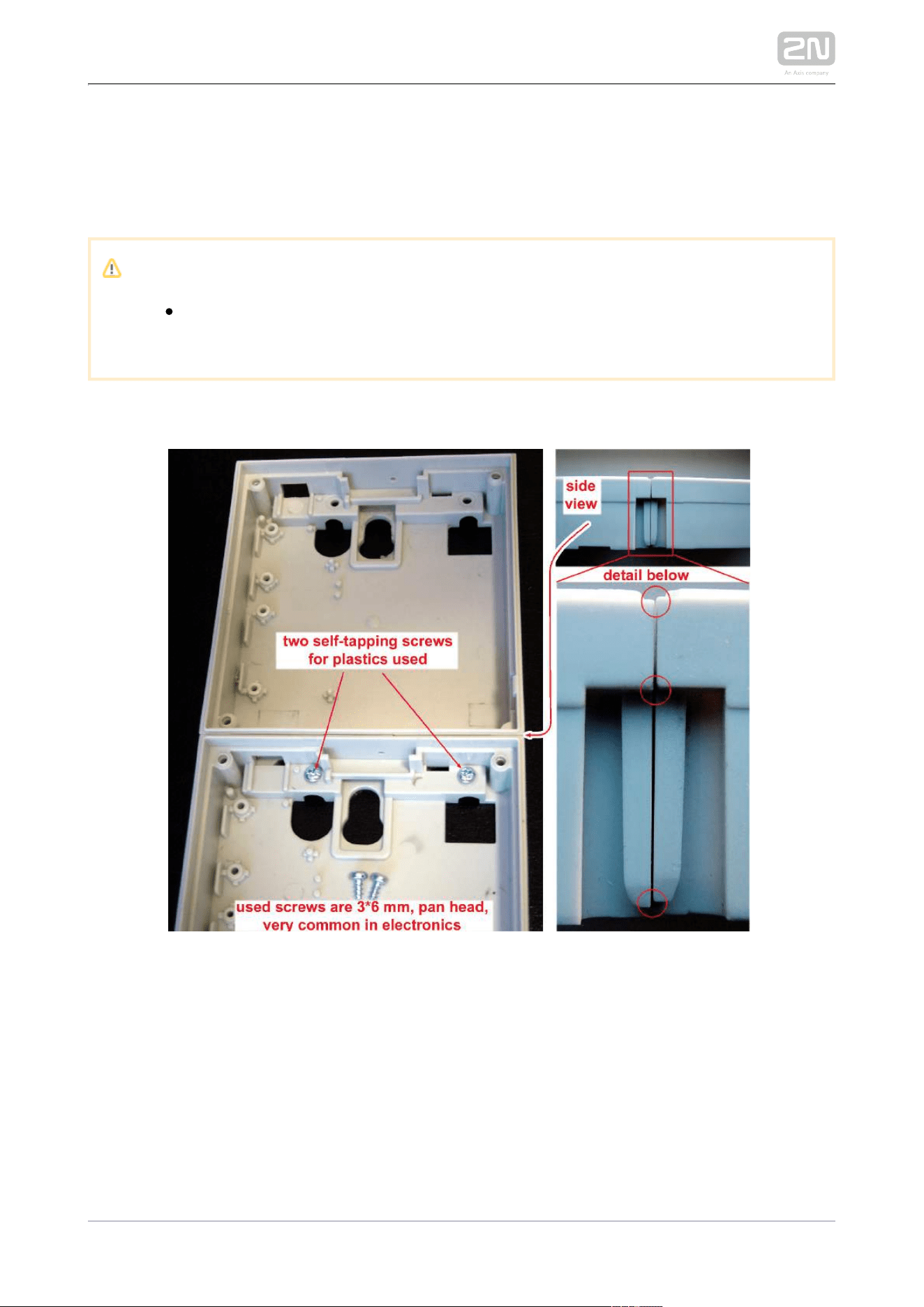
2N TELEKOMUNIKACE a.s., www.2n.cz 290/319
Most Frequent Mounting Errors
At first, mount the metal bolts, level the bases on an even surface and tighten the
screws.
Caution
Make sure that the bases are levelled properly to avoid water leakage
and electronic damage.
The examples in the figures below show incorrectly assembled bases. This happens, in
particular, where the screws are tightened first.
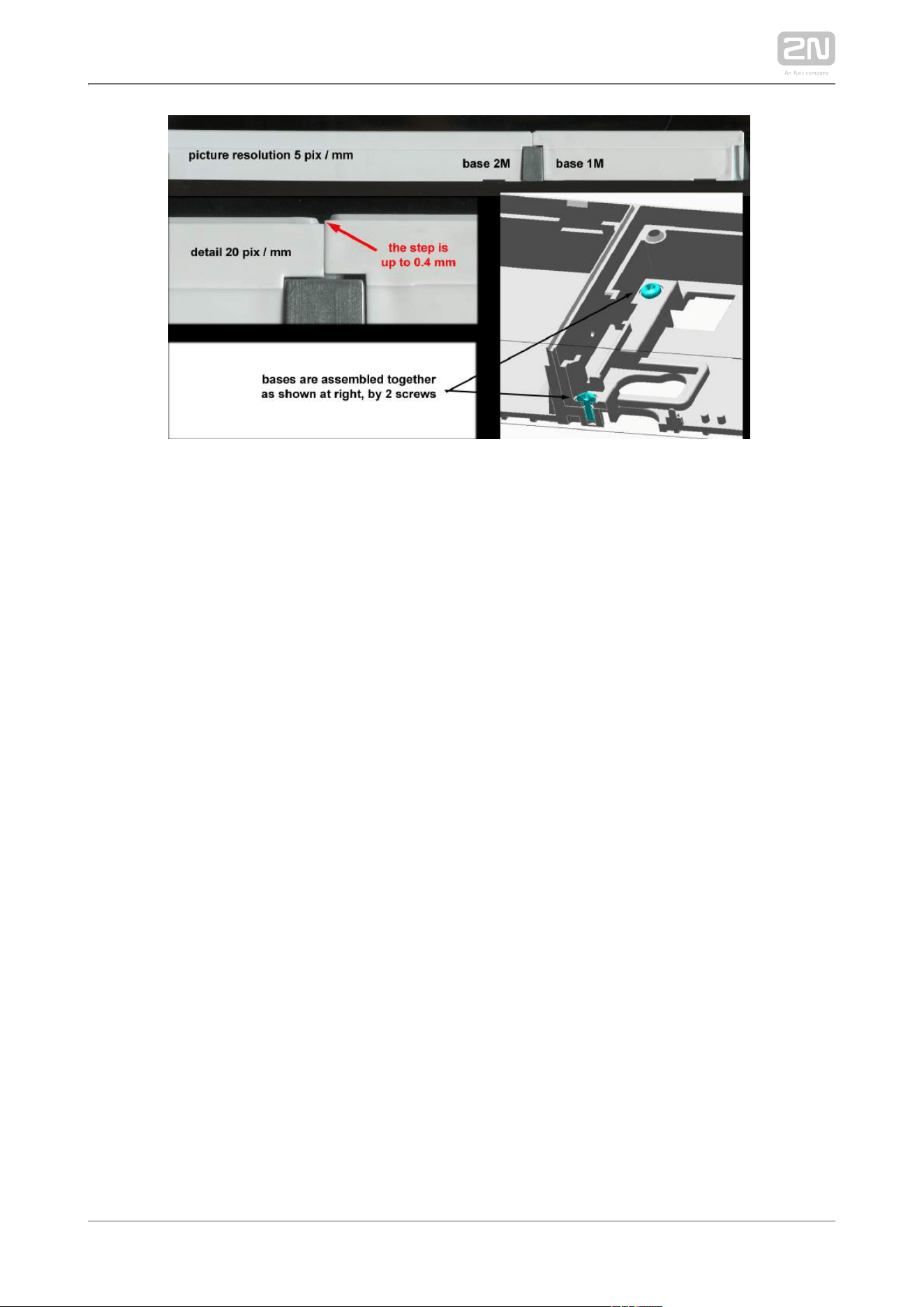
2N TELEKOMUNIKACE a.s., www.2n.cz 291/319

2N TELEKOMUNIKACE a.s., www.2n.cz 292/319
3. Function and Use
This section describes the basic and extending functions of the the 2N IP Verso
®
product.
Here is what you can find in this section:
3.1 Configuration
3.2 Intercom Control as Viewed by External User
3.3 Touch Display Intercom Control As Viewed by External User
3.4 Intercom Control as Viewed by Internal User
3.5 Maintenance
3.6 Downloads

2N TELEKOMUNIKACE a.s., www.2n.cz 293/319
3.1 Configuration
Configure using your PC with any internet browser:2N IP Verso
®
Launch your internet browser (Internet Explorer, Firefox, etc.).
Enter the IP address of your intercom ( , e.g.).http://192.168.1.100/
Log in using the username and password .Admin 2n
You have to know your intercom IP address to log in to the integrated web server.
Upon purchase, is set to the dynamic IP address mode – it retrieves the 2N IP Verso
®
IP address automatically if there is a properly configured DHCP server in the LAN. If
no DHCP is available, operate in the static IP address mode. Refer to the 2N IP Verso
®
for the configuration details.Configuration Manual 2N IP Verso
®
If your device remains inaccessible (you have forgotten the IP address, the network
configuration has changed, etc.), you can change the network configuration using the
device buttons.
IP Address Retrieval
Take the following steps to retrieve the IP address:2N IP Verso
®
Connect (or, if connected, disconnect and reconnect) to the power 2N IP Verso
®
supply.
Wait for the second sound signal .
Press the quick dial button on the main unit 5 times.
2N IP Verso
®
will read its IP address.
If the address is 0.0.0.0, it means that the intercom has not obtained the IP
address from the DHCP server.
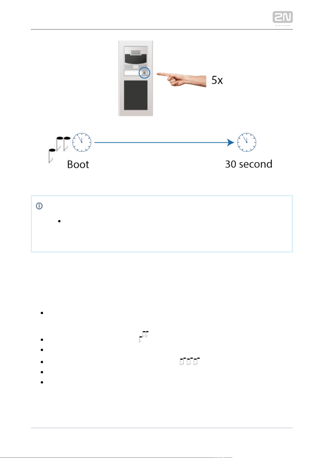
2N TELEKOMUNIKACE a.s., www.2n.cz 294/319
Note
Be sure to press the button sequence within thirty seconds after the
sound signal for security reasons. Up to 2 s intervals are allowed
between the presses.
Dynamic/Static IP Address Switching
Take the following steps to switch the dynamic and static IP address mode in
:2N IP Verso
®
Connect (or, if connected, disconnect and reconnect) to the power 2N IP Verso
®
supply.
Wait for the first sound signal .
Press the quick dial button on the main unit 15 times.
Switching is signalled with the sound signal .
Wait until the device is restarted automatically.
Upon restart, the static IP address mode will be switched to the dynamic IP
address mode and vice versa.
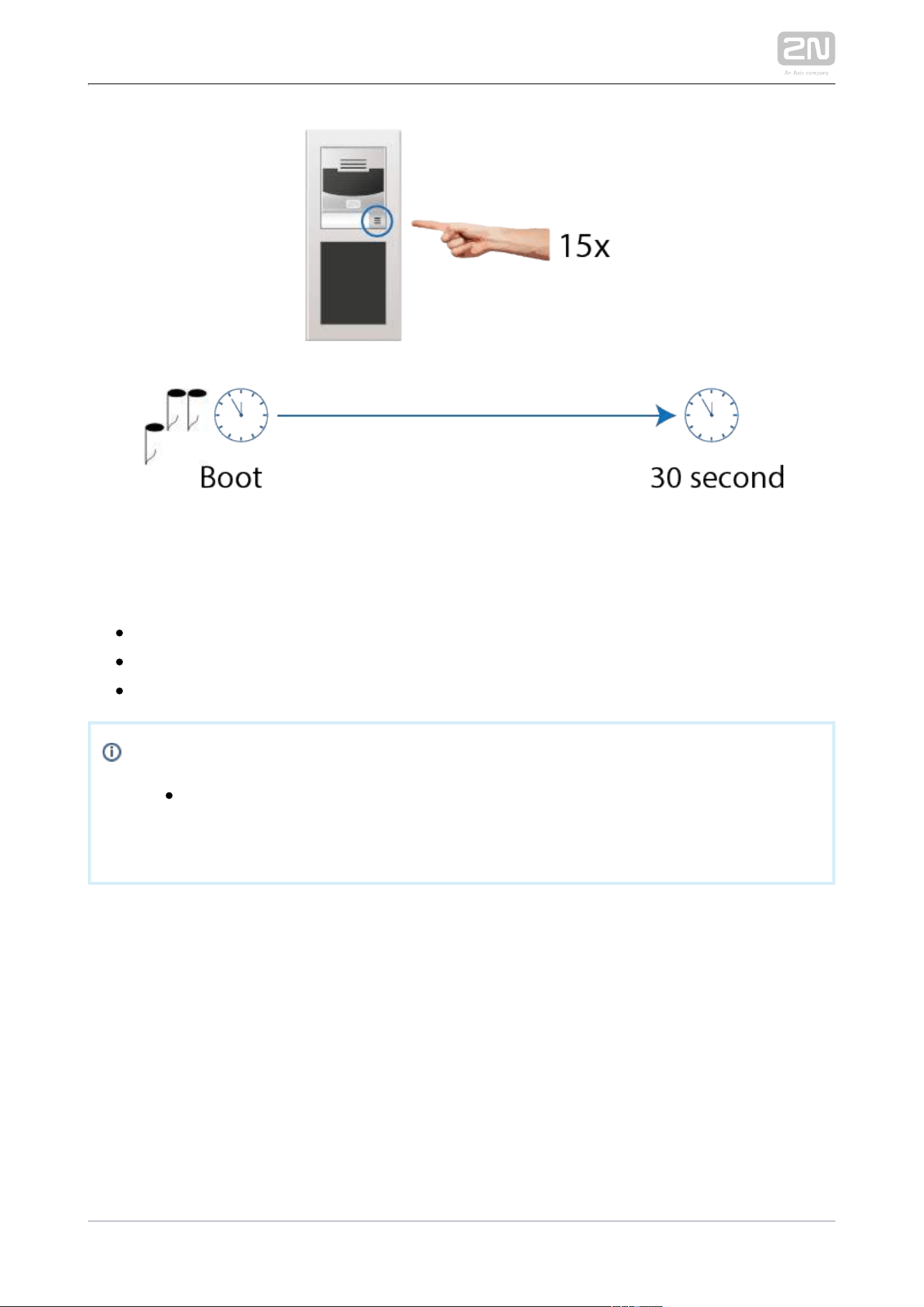
2N TELEKOMUNIKACE a.s., www.2n.cz 295/319
The following network parameters will be set after the static IP address mode is
switched on and the device is restarted:
IP address: 192.168.1.100
Network mask: 255.255.255.0
Default gateway: 192.168.1.1
Note
Be sure to press the button sequence within thirty seconds after the
sound signal for security reasons. Up to 2 s intervals are allowed
between the presses.

2N TELEKOMUNIKACE a.s., www.2n.cz 296/319
3.2 Intercom Control as Viewed by External
User
Quick Dial Buttons
Press the quick dial button on the main unit to dial the first position in the phone
directory (Phone Book) depending on the model type. Use extending modules to
extend the number of quick dial buttons to up to 146.
By pressing the quick dial buttons you dial the phone numbers assigned to the
particular Phone Book position. Call setup is signalled by a long intermittent or any
other tone depending on the configuration of the PBX connected.
Repeated pressing of one and the same quick dial button during call setup may
initiate call hangup or call termination plus dialling the next phone number of the
called subscriber, or may be assigned no function; refer to the Intercom Configuration
/ Hardware / Keypad subsection of Configuration Manual.
You can also press the button anytime to hang up if enabled so in the Button
parameter; refer to the Intercom Configuration / Hardware / Function During Call
Keypad subsection of Configuration Manual.
Calling to Phone Book Position
The Phone Book can contain up to 1999 programmable positions. The 2N IP Verso
®
quick dial buttons can only be used for positions 1 through 146, depending on the
number of actually installed buttons. You can dial the other positions using the
numeric keypad if the function is enabled; refer to the Dial by Numeric Keypad
Intercom Configuration / Hardware / Keypad subsection of Configuration Manual.
Procedure:
Enter the position number using the numeric keypad (05, 15, 200, e.g. – two
digits at least and four digits at most) and press the button for confirmation.
You can also press the button anytime to hang up if enabled so in the Button
parameter; refer to the Intercom Configuration / Hardware Function During Call
/ Keypad subsection of Configuration Manual.

2N TELEKOMUNIKACE a.s., www.2n.cz 297/319
1.
2.
3.
4.
Calling to User-Defined Phone Number
If the (refer to the Intercom Configuration / Hardware / Telephone function enabled
Keypad subsection of Configuration Manual) parameter is selected, you can dial a user-
defined phone number using the numeric keypad.2N IP Verso
®
Procedure:
Press .
You will hear a continuous tone from the speaker.
Enter the phone number via the numeric keypad and press again to confirm
your dialling.
You can also press the button anytime to hang up if enabled so in the Button
parameter; refer to the Intercom Configuration / Hardware Function During Call
/ Keypad subsection of Configuration Manual.
Incoming Call Answering/Rejecting
If the automatic incoming call answering function is disabled (refer to the Intercom
Configuration / Services / Phone / Calls subsection of Configuration Manual), the
incoming call to is signalled with loud ringing. Press to answer the call 2N IP Verso
®
and to reject the call.
Door Opening (Switch Activation) by Code
2N IP Verso
®
is equipped with a door unlocking switch. Enter the valid code (refer to
the Intercom Configuration / Hardware / Switches subsection of Configuration
Manual) using the numeric keypad to activate this switch.
Procedure:
Enter the switch activating numerical code using the numeric keypad and press
for confirmation.
A valid code is notified visually and by a continuous switch activation tone or a
predefined unlocking user sound. An invalid code or interruption longer than as
defined in Timeout for Entering Numbers is signalled by the sound or a
user sound.
2N TELEKOMUNIKACE a.s., www.2n.cz 298/319
Door Opening (Switch Activation) by Biometric Reader
A biometric reader helps authenticate human fingerprints for control and management
of access and third party devices. Refer to Directory / Users for how to load a
fingerprint into a user profile.
Procedure:
Apply your finger to the reader scanning area.
Reader authentication light signalling:
Green – the fingerprint has been recognised successfully.
Green flashes to red – the fingerprint has been recognised but access is
denied. Check the user time profile setting state and multiple
authentication setting. Access can also be blocked by a previous tamper
switch blocking.
Red – the fingerprint has not been recognised .
Note
A higher moisture may deteriorate finger papillary line scanning. You are
advised to dry your finger and the reader scanning surface for successful
authentication.

2N TELEKOMUNIKACE a.s., www.2n.cz 299/319
3.3 Touch Display Intercom Control As
Viewed by External User
The model can be equipped with a colour LCD display, which displays 2N IP Verso
®
the device states (call progress, door opening, etc.) and can work in several modes.
Until the display configuration is loaded, displays no users to be called in 2N IP Verso
®
the Directory menu. If configured properly, the starts displaying an Ad 2N IP Verso
®
menu or the Directory/Keypad introductory menu or separate Directory or Keypad
menus. Control a display-equipped intercom by touching the display and 2N IP Verso
®
browsing.
Presentation
In the Presentation mode, one or more images defined by the available display
configuration are displayed. The Presentation mode is started automatically when the
presentation delay timeout set in the 2N® IP Verso web interface expires. The mode
can be terminated by a touch of the icon, which moves into the 2N IP Verso
®
display introductory menu, or by an incoming call to .2N IP Verso
®
2N TELEKOMUNIKACE a.s., www.2n.cz 300/319
Contacts
In the Contacts mode, a structured list of users defined by the available display
configuration is displayed. The user list can be divided into a practically arbitrary
count of groups. Browse through the Directory by touching the display. Click
to return to the superior group or the display introductory menu. Touch the user name
to make a call in the Contacts mode.
This mode helps you quick search contacts too. Touch the display icon to switch
the Contacts into the search mode and enter the string to be searched via the
touchpad. See the string in the status line in the upper part of the display. Touch the
display icon to delete the currently last character of the text to be searched. The
string is searched for in the current group and subgroup levels. See the count of found
users in the right-hand upper corner of the display. Touch the found contacts and
browse through the data.
The Contacts menu also includes a Help submenu in the right-hand bottom corner of
the display, which provides tips and basic display controls for the Contacts mode.
2N TELEKOMUNIKACE a.s., www.2n.cz 301/319
Call
Use the Call mode to make calls to the intercom Directory users.
To call a user, set Dialling via keypad in the intercom web interface and select one of
the following options: Disabled, User position number or User virtual number. If you
set User position number or User virtual number, just enter the number and click
for confirmation. Click to get back to the display introductory
menu.
2N TELEKOMUNIKACE a.s., www.2n.cz 302/319
Entry
The Entry mode helps you enter the switch codes. Enter the switch digital code and
click
for confirmation. You can also enable Scramble keypad in the Keypad mode via the
web interface to scramble the numerical keypad buttons before every new display in
order to prevent third persons from seeing the code to be entered.

2N TELEKOMUNIKACE a.s., www.2n.cz 303/319
3.4 Intercom Control as Viewed by Internal
User
Call Answering
You can answer the incoming calls to the intercom using your phone like 2N
®
IP Verso
any other calls. You can unlock the door, activate/deactivate a user/profile via your
phone keypad during the call. The calls, however, are time-limited to avoid
unintentional blocking of the line. Set the maximum call duration in the 2N
®
IP Verso
(refer to the Intercom Configuration / Services / Phone / Calls Call time limit
subsection of Configuration Manual). Press # on your phone anytime to extend the call
time. The automatic call termination is signalled with a short beep 10 s before the call
end.
Calling to 2N ® IP Verso
2N
®
IP Verso allows you to answer incoming calls. Set the required parameters in the
Incoming calls group; refer to the Intercom Configuration / Services / Phone / Calls
subsection of Configuration Manual.
Door Opening (Switch Activation) by Code
2N
®
IP Verso is equipped with a door unlocking switch. Enter the valid code (refer to
the Intercom Configuration / Hardware / Switches subsection of Configuration
Manual) using your phone keypad to activate this switch.
Procedure:
Enter the switch 1 or 2 activating code using your phone keypad and press for
confirmation. Confirmation is unnecessary if the Lock code without confirmation
is enabled, refer to the Intercom Configuration / Hardware / Switches /
Advanced subsection of Configuration Manual.
A valid code is signalled by the sound. An invalid code or interruption longer
than as defined in is signalled by the Timeout for Entering Numbers
sound.

2N TELEKOMUNIKACE a.s., www.2n.cz 304/319
Profile Activation/Deactivation
Activate/deactivate a profile using your phone in order to route calls directly to the
phone numbers tied with the profile, refer to the Intercom Configuration / Directory /
Time Profiles subsection of Configuration Manual for details.
Procedure:
Enter the profile activating/deactivating code using your phone keypad and
press for confirmation.
A valid code is signalled by the or sound according to the code type.
An invalid code or interruption longer than as defined in Timeout for Entering
is signalled by the sound.Numbers
2N TELEKOMUNIKACE a.s., www.2n.cz 305/319
3.5 Maintenance
Cleaning
If used frequenly, the device surface, the keypad in particular, gets dirty. To clean it,
use a piece of soft cloth moistened with clean water. We recommend you to follow
these principles while cleaning:
Never use aggressive detergents (such as abrasives or strong disinfectants).
Use suitable cleaning agents for glass lens cleaning (cleaners for glasses, optic
devices screens, etc.)
Clean the device in dry weather in order to make waste water evaporate quickly.
Warning
Prevent water from getting inside the intercom.
Do not use alcohol-based cleaners.
Avoid peroxide-based cleaners.
Caution
Always use the product for the purpose it was designed and
manufactured for, in compliance herewith.
The manufacturer reserves the right to modify the product in order to
improve its qualities.
2N
®
Verso contains no environmentally harmful components. When the
product's service life is exhausted and you would like to dispose of it
please do so in accordance with applicable legal regulations.


2N TELEKOMUNIKACE a.s., www.2n.cz 307/319
4. Technical Parameters
Signalling protocol
SIP (UDP, TCP, TLS)
Buttons
Button design: white-backlit transparent buttons with replaceable nametags
Button count: 1 and increments of 5
Button extenders: up to 29 modules, limited by power supply
Numeric keypad: optional
Audio
Microphone: 1 integrated microphone
Amplifier: 2 W (class D) amplifier
Speaker: 2 W / 8 Ω
Sound pressure level (SPL max): 78 dB (for 1 kHz, distance 1 m)
Output LINE OUT: 1 VRMS / 600 Ω
Volume control: adjustable with automatic adaptive mode
Full duplex: yes (AEC)
Speech transmission index (STI): 0.89
Audio stream
Protocols: RTP / RTSP
Codecs: G.711, G.729, G.722, L16/16 kHz
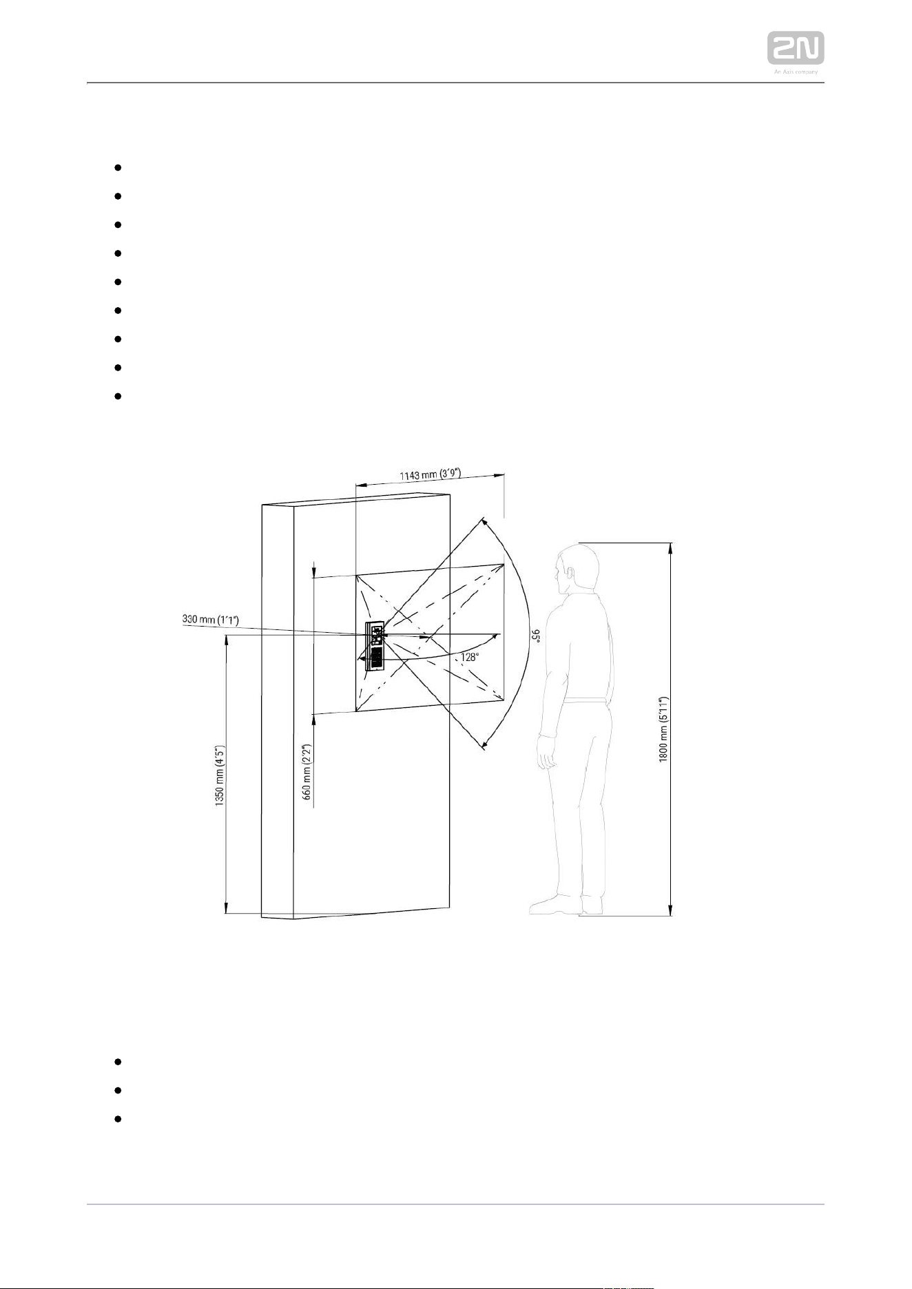
2N TELEKOMUNIKACE a.s., www.2n.cz 308/319
Camera
Sensor: 1/3'' colour CMOS
JPEG resolution: up to 1280 (H) x 960 (V)
Video resolution: 640 (H) x 480 (V)
Frame rate: up to 30 snapshots/s
Sensor sensitivity: 5.6 V/lux-sec (550 nm)
View angle: 128 ° (H), 95 ° (V), 134 ° (D)
Infrared light: yes
Sensor sensitivity without IR light: 0,1 Lux ± 20 %
Focal length: 2.25 mm
Video stream
Protocols: RTP / RTSP / HTTP
Codecs: H.263, H.263+, H.264, MPEG-4, M-JPEG
IP camera function: yes, ONVIF v2.4 profile S compatible

2N TELEKOMUNIKACE a.s., www.2n.cz 309/319
Bandwidth
Audio codecs
PCMA, PCMU – 64 kbps (with 85.6 kbps headers)
G.729 – 16 kbps (with 29.6 kbps headers)
G.722 – 64 kbps (with 85.6 kbps headers)
L16 / 16 kHz – 256 kbps (with 277.6 kbps headers)
V i d e o c o d e c s
Set the video codec data flows in the Services / Phone / Video menu for calls
and in the Services / Streaming / RTSP menu for streaming. The set bandwidth
represents the value that the codec has to approach on a long-time average. The
data flows can vary depending on the scene to be scanned.
The measured data flow values correspond to the test view of a person standing
in front of the intercom.
H.264
Low quality: QVGA (320 x 240), 10 fps, 256 kbps: 181 kbps (with 190 kbps
headers)
Medium quality: VGA (640 x 480), 15 fps, 768 kbps: 600 kbps (with 661
kbps headers)
High quality: VGA (640 x 480), 30 fps, 2048 kbps: 1319 kbps (with 1372
kbps headers)
MJPEG
Low quality: QVGA (320 x 240), 10 fps, quality 70: 435 kbps with headers
Medium quality: VGA (640 x 480), 15 fps, quality 85: 506 kbps
High quality: SXGA (1280 x 960), 15 fps, quality 95: 8 Mbps
Interface
Power supply: 12 V ±15 % / 2 A DC or PoE
PoE: PoE 802.3af (Class 0–12.95 W)
LAN: 10/100BASE-TX with Auto-MDIX, RJ-45
Recommended cabling: Cat-5e or higher
Supported protocols: SIP2.0, DHCP opt. 66, SMTP, 802.1x, RTSP, RTP, TFTP,
HTTP, HTTPS, Syslog, ONVIF
Passive switch: NO/NC contact, up to 30 V / 1 A AC/DC
Active switch output: 8 up to 12 V DC depending on power supply (PoE: 10 V;
adaptor: power supply voltage minus 2 V), up to 400 mA

2N TELEKOMUNIKACE a.s., www.2n.cz 310/319
RFID card reader
Optionally 125 kHz or 13.56 MHz
Supported cards, 125 kHz, Part No. 9155032:
EM4100, EM4102
Supported cards, 13.56 MHz, Part No. 9155033 (only card serial number is read)
ISO/IEC 14443A
Mifare Classic 1k & 4k, DESFire EV1, Mini, Plus S&X, Ultralight,
Ultralight C
ISO/IEC 14443B
CEPAS, HID iCLASS
JIS X 6319
Felica
Supported cards on 13.56 MHz NFC version, Part No. 9155040 (only card serial
number is read)
ISO/IEC 14443A
Mifare Classic 1k & 4k, DESFire EV1, Mini, Plus S&X, Ultralight,
Ultralight C
ISO/IEC 14443B
CEPAS, HID iCLASS
JIS X 6319
Felica
ISO/IEC 18092
SmartPhone with NFC/HCE support, since Android version 4.3
Supported cards on secured 13.56 MHz NFC version, Part No. 9155042
(optionally card serial number or PAC ID is read)
ISO/IEC 14443A
Mifare Classic 1k & 4k, DESFire EV1, Mini, Plus S&X, Ultralight,
Ultralight C
ISO/IEC 14443B
CEPAS, HID iCLASS
JIS X 6319
Felica
ISO/IEC 18092
SmartPhone with NFC/HCE support, from Android version 4.3 up
Maximum H – field strength at 10 m for 125 kHz version: 66 dBµA/m
Maximum H – field strength at 10 m for 13.56 MHz version: 60 dBµA/m

2N TELEKOMUNIKACE a.s., www.2n.cz 311/319
2N IP Verso – Bluetooth module
®
Bluetooth 4.0 Compliant (Bluetooth Low Energy, BLE)
Security: asymmetric RSA-1024 and symmetric AES-128 encryption
RX sensitivity: up to -93 dBm
Range: adjustable (short ~ 0.5m, medium ~ 2m, long ~ up to 10m)
Power consumption: 20mA at 12V DC
Operational temperature range: -40°C ~ +60°C
Storage temperature range: -40°C ~ +70°C
Dimensions: 97x105x30mm
Compatible with 2N IP Verso, 2N LTE Verso and 2N Access Unit
® ® ®
Mobile app. support: Android 5.0 and higher, iOS 11.0 and higher
Touch display
Resolution: 320 px x 214 px H x V
Resolution slideshow: 214 px x 214 px
Contrast ratio: 400
Brightness: 350 cd/m2
Viewing angle: 80 ° from any direction
Weight: 280 g
Consumption min: 1.36 W
Consumption max: 2.40 W
Working temperature: -20 °C – 60 °C
Resistance level: IK07
I/O module
Dimensions: 43 (W) x 31,5 (H) x 1,5 (D) mm
Wiegand module
: Dimensions 43 (W) x 31,5 (H) x 1,5 (D) mm

2N TELEKOMUNIKACE a.s., www.2n.cz 312/319
Mechanical properties
Cover: robust zinc casting with surface finish (minor surface shade nuances are
acceptable)
91550XX – NICKEL
Material - Zamak 410 - Zn95Al4Cu1
Surface treatment - Zn/Cu20/Ni25b max. 80 µm
91550XXB – BLACK
Material - Zamak 410 - Zn95Al4Cu1
Surface treatment - Cataphoretic coating Black 30 µm, RAL 9004 –
Signalschwarz (colour is not guaranted – it is cataphoretic)
Working temperature: -40 °C – 60 °C
Working relative humidity: 10 % – 95 % (non-condensing)
Storing temperature: -40 °C – 70 °C
Dimensions
Surface mounting frame:
1 module: 107 (W) x 130 (H) x 28 (D) mm
2 modules: 107 (W) x 234 (H) x 28 (D) mm
3 modules: 107 (W) x 339 (H) x 28 (D) mm
Flush mounting frame:
1 module: 130 (W) x 153 (H) x 5 (D) mm
2 modules: 130 (W) x 257 (H) x 5 (D) mm
3 modules: 130 (W) x 361 (H) x 5 (D) mm
Flush mounting box (minimum hole dimensions):
1 module: 108 (W) x 131 (H) x 45 (D) mm
2 modules: 108 (W) x 238 (H) x 45 (D) mm
3 modules: 108 (W) x 343 (H) x 45 (D) mm
Module internal cutout: 72 (W) x 89.3 (H) mm / 2.83 (W) x 3.51 (H) inches
Weight: max net weight: 2 kg / max gross weight: 2.5 kg – based on
configuration
Covering level: IP54
Resistance level: IK08


2N TELEKOMUNIKACE a.s., www.2n.cz 315/319
5.2 Directives, Laws and Regulations
2N IP Verso
®
conforms to the following directives and regulations:
2014/35/EU on the harmonisation of the laws of the Member States relating to the
making available on the market of electrical equipment designed for use within certain
voltage limits
2014/30/EU on the harmonisation of the laws of the Member States relating to
electromagnetic compatibility
2011/65/EU on the restriction of the use of certain hazardous substances in electrical
and electronic equipment
2012/19/EU on waste electrical and electronic equipment
2014/53/EU on the harmonisation of the laws of the Member States relating to the
making available on the market of radio equipment
Industry Canada
This Class B digital apparatus complies with Canadian ICES-003. / Cet appareil
numérique de la classe B est conforme a la norme NMB-003 du Canada.
FCC
NOTE: This equipment has been tested and found to comply with the limits for a Class
B digital device, pursuant to part 15 of the FCC Rules. These limits are designed to
provide reasonable protection against harmful interference in a residential installation.
This equipment generates, uses and can radiate radio frequency energy and, if not
installed and used in accordance with the instructions, may cause harmful interference
to radio communications. However, there is no guarantee that interference will not
occur in a particular installation. If this equipment does cause harmful interference to
radio or television reception, which can be determined by turning the equipment off
and on, the user is encouraged to try to correct the interference by one or more of the
following measures:
Reorient or relocate the receiving antenna
Increase the separation between the equipment and receiver
Connect the equipment into an outlet on a circuit different from that to which
the receiver is connected
Consult the dealer or an experienced radio/TV technician for help.
Changes or modifications to this unit not expressly approved by the party responsible
for compliance could void the user's authority to operate this equipment.

2N TELEKOMUNIKACE a.s., www.2n.cz 316/319
1.
2.
3.
DDA compliance:
2N TELEKOMUNIKACE intercoms comply with the Disability Discrimination Act 2005
(DDA) under the following conditions:
The intercoms are mounted so that their lower edge is between 100 and 120
centimeters above the floor.
The intercoms use a keyboard that has a mechanical protrusion on number 5.
The intercoms use electromagnetic loop as a hearing aid.
Caution
In order to ensure the full functioning and guaranteed outputs we strongly
recommend a verification of the timeliness of version of product or facility
already during the installation process. The customer takes into consideration
that the product or facility can achieve the guaranteed outputs and be fully
operational pursuant to the producer’s instructions only by using the most
recent version of product or facility, which has been tested for full
interoperability and has not been determined by the producer as incompatible
with certain versions of other products, only in conformity with the producer’s
instructions, guidelines, manual or recommendation and only in conjunction
with suitable products and facilities of the other producers. The most recent
versions are available on the website https://www.2n.cz/cs_CZ/, or specific
facilities, depending on their technical capacity, allow updating in the
configuration interface. Should the customer use any other version of product
or facility than the most recent one, or the version that has been determined
by the producer as incompatible with certain versions of other producers’
products of facilities, or the product or facility in a way incompatible with the
producer’s instructions, guidelines, manual or recommendation or in
conjunction with unsuitable products or facilities of the other producers, he or
she is aware of all potential limitations of functionality of such a product or
facility and all relating consequences. Should the customer use any other than
the most recent version of the product or facility, or the version that has been
that has been determined by the producer as incompatible with certain
versions of other producers’ products of facilities, or the product or facility in
a way incompatible with the producer’s instructions, guidelines, manual or
recommendation or in conjunction with unsuitable products or facilities of the
other producers, he or she agrees that the company 2N TELEKOMUNIKACE a.
s. is not liable neither for any limitation of such a product’s functionality, nor
for any damage, loss or injury relating to such a potential limitation of
functionality.

2N TELEKOMUNIKACE a.s., www.2n.cz 317/319
5.3 General Instructions and Cautions
Please read this User Manual carefully before using the product. Follow all instructions
and recommendations included herein.
Any use of the product that is in contradiction with the instructions provided herein
may result in malfunction, damage or destruction of the product.
The manufacturer shall not be liable and responsible for any damage incurred as a
result of a use of the product other than that included herein, namely undue
application and disobedience of the recommendations and warnings in contradiction
herewith.
Any use or connection of the product other than those included herein shall be
considered undue and the manufacturer shall not be liable for any consequences
arisen as a result of such misconduct.
Moreover, the manufacturer shall not be liable for any damage or destruction of the
product incurred as a result of misplacement, incompetent installation and/or undue
operation and use of the product in contradiction herewith.
The manufacturer assumes no responsibility for any malfunction, damage or
destruction of the product caused by incompetent replacement of parts or due to the
use of reproduction parts or components.
The manufacturer shall not be liable and responsible for any loss or damage incurred
as a result of a natural disaster or any other unfavourable natural condition.
The manufacturer shall not be held liable for any damage of the product arising during
the shipping thereof.
The manufacturer shall not make any warrant with regard to data loss or damage.
The manufacturer shall not be liable and responsible for any direct or indirect damage
incurred as a result of a use of the product in contradiction herewith or a failure of the
product due to a use in contradiction herewith.
All applicable legal regulations concerning the product installation and use as well as
provisions of technical standards on electric installations have to be obeyed. The
manufacturer shall not be liable and responsible for damage or destruction of the
product or damage incurred by the consumer in case the product is used and handled
contrary to the said regulations and provisions.
The consumer shall, at its own expense, obtain software protection of the product.
The manufacturer shall not be held liable and responsible for any damage incurred as
a result of the use of deficient or substandard security software.

2N TELEKOMUNIKACE a.s., www.2n.cz 318/319
The consumer shall, without delay, change the access password for the product after
installation. The manufacturer shall not be held liable or responsible for any damage
incurred by the consumer in connection with the use of the original password.
The manufacturer also assumes no responsibility for additional costs incurred by the
consumer as a result of making calls using a line with an increased tariff.
Electric Waste and Used Battery Pack Handling
Do not place used electric devices and battery packs into municipal waste containers.
An undue disposal thereof might impair the environment!
Deliver your expired electric appliances and battery packs removed from them to
dedicated dumpsites or containers or give them back to the dealer or manufacturer
for environmental-friendly disposal. The dealer or manufacturer shall take the product
back free of charge and without requiring another purchase. Make sure that the
devices to be disposed of are complete.
Do not throw battery packs into fire. Battery packs may not be taken into parts or
short-circuited either.

2N TELEKOMUNIKACE a.s., www.2n.cz 319/319
2N TELEKOMUNIKACE a.s.
Modřanská 621, 143 01 Prague 4, Czech Republic
Phone: +420 261 301 500, Fax: +420 261 301 599
E-mail: [email protected]
Web: www.2n.cz
v2.15