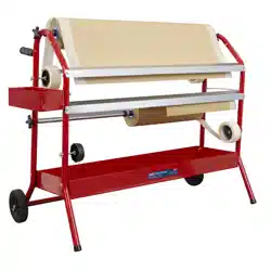
MASKING PAPER DISPENSER TROLLEY
2 X 900MM
MODEL NO: MK67.V2
Thank you for purchasing a Sealey product. Manufactured to a high standard, this product will, if used according to these instructions,
and properly maintained, give you years of trouble free performance.
IMPORTANT: PLEASE READ THESE INSTRUCTIONS CAREFULLY. NOTE THE SAFE OPERATIONAL REQUIREMENTS, WARNINGS & CAUTIONS. USE
THE PRODUCT CORRECTLY AND WITH CARE FOR THE PURPOSE FOR WHICH IT IS INTENDED. FAILURE TO DO SO MAY CAUSE DAMAGE AND/OR
PERSONAL INJURY AND WILL INVALIDATE THE WARRANTY. KEEP THESE INSTRUCTIONS SAFE FOR FUTURE USE.
1. SAFETY
9 Ensure the dispenser is on a reasonably flat, level
floor before loading.
9 Be aware that the paper cutting blades are sharp,
handle with care.
8 DO NOT use the dispenser for any purpose other
than that for which it is designed.
2. INTRODUCTION
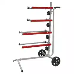
Two roll dispenser accepts rolls up to 900mm and features
storage tray underneath dispenser unit. Automatically applies
adhesive tape to edges of masking paper. Papers and tapes
not included.
3. SPECIFICATION
Model no ................................................................. MK67.V2
Capacity ................................................2 x 900mm paper roll
4. ASSEMBLY
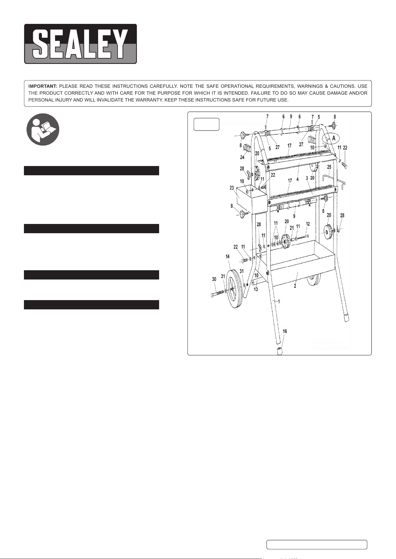
4.1. To assemble the side frames compress the silver latch
button at the top of the front leg 1B and insert the tube into
the back leg tube 1A until they snap together. (See A in
fig.1).
4.2. Onto each end of the two paper bars 9 slide a large
retaining washer 6 followed by a retaining spring 27
followed by a black plastic retaining ring 5. Insert a screw 7 into the threaded block on each retaining ring.
4.3. Attach the side frames to each end of the paper bars as shown in Fig.1 using the four black knobs 8.
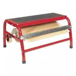
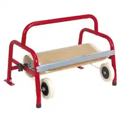
4.4. Fit the bottom tray between the side frames and bolt it to each leg using a bolt 22, a washer 11 and a nut 10.
4.5. Attach the upper paper blade 4 to the front of the frame using two bolts 22, two washers 11 and two nuts 10. (The upper blade has a
wider profile than the lower blade).
4.6. Attach the lower paper cutter 3 to the front of the frame using two bolts 22, two washers 11 and two nuts 10.
4.7. Attach a paper spring 17 to the back edge of each paper cutter. Hook one end of the spring to the notched back corner of the metalwork
and stretch it across and hook it to the other back corner. Take care to avoid the paper cutter teeth when doing this.
4.8. To assemble the four tape reels as shown in fig.1 take a long bolt 12 and drop a washer 11 onto it followed by a black plastic hub
21. Slide a reel 20 over the bolt and onto the hub ensuring that it is the right way round. Retain the assembly using another
washer followed by a nut.
4.9. After the nut has been tightened the reel should still run freely on the hub. Attach another nut to the bolt and insert the bolt through the
frame in one of the four places indicated in fig.1. Retain the assembly in place using a wing nut 28 and a washer 11.
4.10. Attach the top tray 23 to the side of one of the frames using two bolts 22, two washers 11 and two nuts 10. The nuts and washers should
be on the inside of the tray.
4.11. Attach the hanger 25 to the side of the opposite frame at the same level as the top tray. Insert the ends of the hanger into the holes in
the side of the frame and tip the hanger forwards so that the first bend in either end of the hanger is inside each frame tube.
4.12. The dispenser has a tubular axle which allows an axle bolt to be screwed into either end and also fixes the axle to the frame.
4.13. Slide a washer 31 over a bolt 30 followed by a wheel 14 and another washer 31. Position the tubular axle 13 between the two rear legs
and pass the axle bolt through the rear leg and screw it into the thread in the end of the axle. Attach the other wheel in the same way.
Tighten the axle bolts until the wheel is lightly gripped then back off slightly to allow the wheels to rotate.
Refer to
instruction
manual
Original Language Version
© Jack Sealey Limited
MK67.V2 | Issue:2 (H,F) 06/03/20
fig.
1
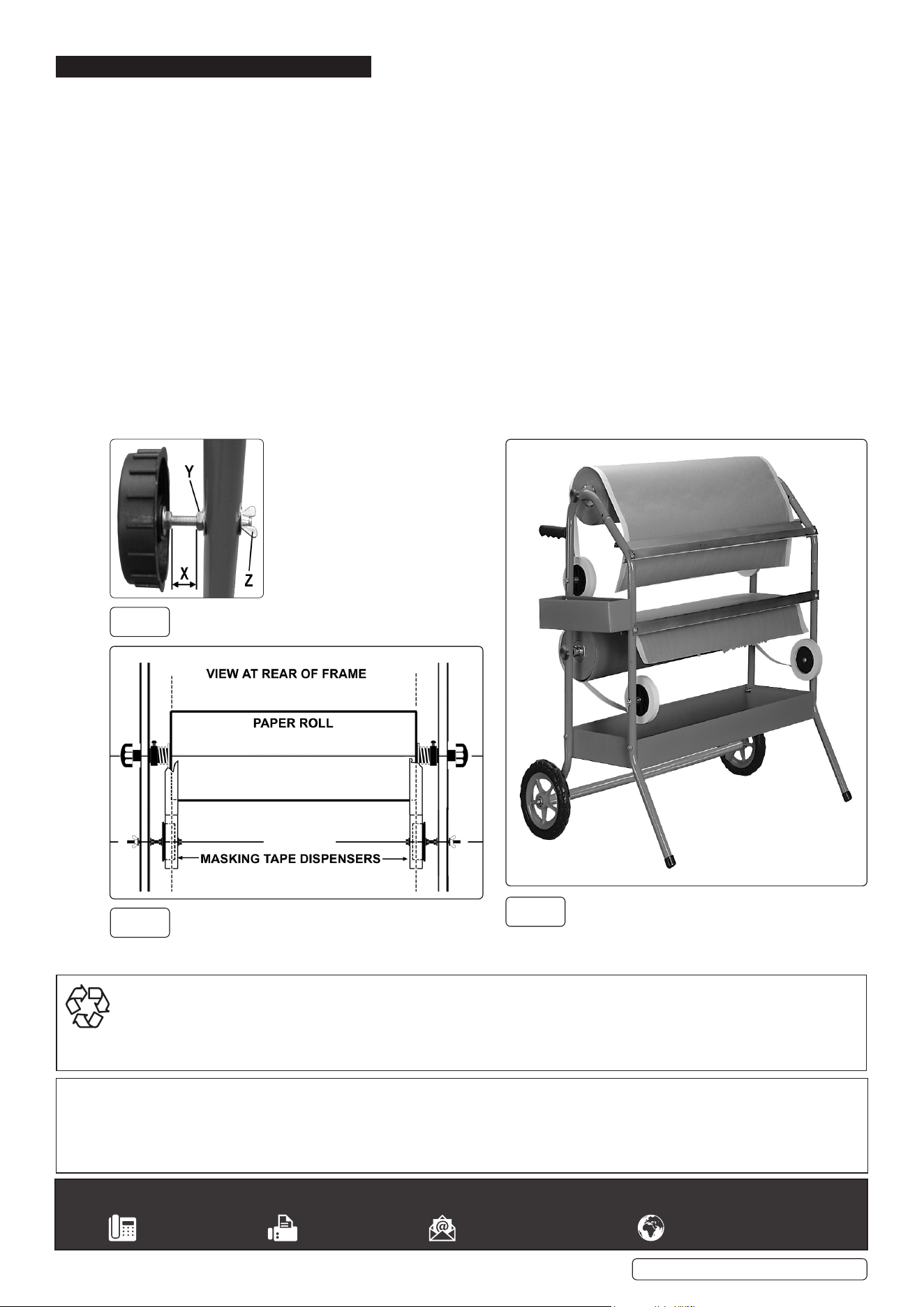
fig.
2
fig.
4
Original Language Version
© Jack Sealey Limited
MK67.V2 | Issue:2 (H,F) 06/03/20
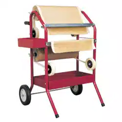
5. OPERATIONi
5.1. Remove either the upper or lower paper bar from the frame by unscrewing and removing the black knobs at either end.
5.2. Loosen the screw in one of the black plastic retaining rings and remove the ring, spring and washer from the end of the bar.
Remove the cardboard tube centre of the last roll from the bar.
5.3. Slide the the paper bar through the centre of the new paper roll and refit the washer, spring and retainer to the end of the bar.
Temporarily tighten the screw in the black retaining ring.
5.4. To refit the loaded bar to the frame get a second person or persons to support the paper roll while the black knobs are fitted at either end
of the bar. The paper should be coming off the top of the roll. Once loaded, check that the roll is centrally placed on the paper bar and
make any necessary adjustments using the black retaining rings.
5.5. Push a roll of masking tape onto each tape dispensing reel and spin it to make sure the tape is running true. Check that the tape
dispensers are aligned with the ends of of the paper roll as shown in fig.3.
(The centre line of the tape should align with the edges of the paper roll). The position of the tape dispensers can also be adjusted as
shown in fig.2. To increase or decrease dimension ’X’ loosen the wing nut ‘Z’ and roll nut ’Y’ up or down the bolt as required. Re-tighten
the wing nut.
5.6. Pull about 18” of paper from the roll and feed it between the paper spring and the back edge of the adjacent paper cutter.
5.7. Pull tape from each dispenser in turn and stick it to the paper roll so that it is half on and half off the paper edges. Check the alignment of
the tapes and make any further adjustments required to the positions of the tape dispensers.
5.8. Slowly pull the paper from the roll and check that the tapes feed correctly onto the edges of the paper.
5.9. Tear the paper off with an upward movement against the down facing teeth of the paper blade. Keep hands well away from the blade
when doing this.
5.10. Load the other paper bar as described above.
NOTE: A fully loaded frame is quite heavy. Take care when moving it and always leave it in a stable position.
.
fig.
3
Sealey Group, Kempson Way, Suffolk Business Park, Bury St Edmunds, Suffolk. IP32 7AR
01284 757500 01284 703534 sales@sealey.co.uk www.sealey.co.uk
ENVIRONMENT PROTECTION
Recycle unwanted materials instead of disposing of them as waste. All tools, accessories and packaging should be sorted, taken to
a recycling centre and disposed of in a manner which is compatible with the environment. When the product becomes completely
unserviceable and requires disposal, drain any fluids (if applicable) into approved containers and dispose of the product and fluids
according to local regulations.
Note: It is our policy to continually improve products and as such we reserve the right to alter data, specifications and component parts without prior
notice .Please note that other versions of this product are available. If you require documentation for alternative versions, please email or call
our technical team on technical@sealey.co.uk or 01284 757505.
Important: No Liability is accepted for incorrect use of this product.
Warranty: Guarantee is 12 months from purchase date, proof of which is required for any claim.