
GV-IP Camera
Before attempting to connect or operate this product,
please read these instructions carefully and save this manual for future use.
Box Camera
Ultra Box Camera
Arctic Box Camera
Target Box Camera
ICH265HISIV114-A
Quick Start Guide

© 2018 GeoVision, Inc. All rights reserved.
Under the copyright laws, this manual may not be copied, in whole or in
part, without the written consent of GeoVision.
Every effort has been made to ensure that the information in this manual is
accurate. GeoVision, Inc. makes no expressed or implied warranty of any
kind and assumes no responsibility for errors or omissions. No liability is
assumed for incidental or consequential damages arising from the use of
the information or products contained herein. Features and specifications
are subject to change without notice. Note: no memory card slot or local
storage function for Argentina.
GeoVision, Inc.
9F, No. 246, Sec. 1, Neihu Rd.,
Neihu District, Taipei, Taiwan
Tel: +886-2-8797-8377
Fax: +886-2-8797-8335
http://www.geovision.com.tw
Trademarks used in this manual: GeoVision, the GeoVision logo and GV
series products are trademarks of GeoVision, Inc.
July 2018

Contents
Caution................................................................................v
Safety Notice ......................................................................v
Options ..............................................................................vi
Creating GV-IP Camera’s Login Credentials............... viii
Note for Installing Camera Outdoor............................... ix
Note for USB Storage and WiFi Adapter ........................ x
Note for Silica Gel Bags................................................... x
Chapter 1 Box Camera .................................................... 1
1.1 Packing List................................................................................6
1.1.1 For H.265 Cameras ...................................................... 6
1.1.2 For H.264 Cameras ...................................................... 7
1.2 Overview....................................................................................8
1.2.1 GV-BX120D / 130D Series / 140DW / 220D Series /
320D Series / 520D.................................................................8
1.2.2 GV-BX1200 Series / 1300 Series / 1500 Series / 2400
Series / 2500 Series / 2600 / 2700 Series /3400 Series / 4700
Series / 5300 Series / 5700 Series / 12201 ..........................10
1.3 Connecting the Camera...........................................................13
1.3.1 GV-BX120D / 130D Series / 140DW / 220D Series /
320D Series / 520D...............................................................13
i

1.3.2 GV-BX1200 Series / 1300 Series / 1500 Series / 2400
Series / 2500 Series / 2600 / 2700 Series / 3400 Series / 4700
Series / 5300 Series / 5700 Series / 12201 ..........................15
1.4 Accessory Installation ..............................................................17
1.4.1 C-Mount Lenses..........................................................17
1.4.2 Infrared Illuminators (Optional) ...................................18
1.5 I/O Terminal Block ...................................................................19
1.5.1 Pin Assignment ...........................................................19
1.5.2 Connecting to GV-Relay V2 (Optional) ....................... 20
1.6 Loading Factory Default........................................................... 21
1.6.1 Using the Web Interface .............................................21
1.6.2 Directly on the Camera ...............................................22
Chapter 2 IR Arctic Box Camera .................................. 23
2.1 Packing List..............................................................................24
2.2 Overview..................................................................................27
2.2.1 GV-BX120D-E / 220D-E / 320D-E / 520D-E / 1500-E /
2400-E / 3400-E / 4700-E / 5300-E.......................................27
2.2.2 GV-BX2510-E / 5310-E................................................ 28
2.3 Installation................................................................................ 29
2.4 Connecting the Camera...........................................................35
2.4.1 GV-BX120D-E / 220D-E / 320D-E / 520D-E / 1500-E /
2400-E / 3400-E / 4700-E / 5300-E.......................................35
ii

2.4.2 GV-BX2510-E / 5310-E............................................... 37
2.5 Notice for Using the IR Arctic Box Camera..............................40
2.5.1 Enabling IR LED after Loading Default ....................... 41
2.5.2 Disabling Status LED under Low Light Conditions .....42
2.6 Loading Factory Default........................................................... 43
2.6.1 Using the Web Interface ..............................................43
2.6.2 Directly on the Camera ................................................43
Chapter 3 Ultra Box Camera......................................... 44
3.1 Packing List..............................................................................45
3.2 Overview...................................................................................46
3.3 Installation................................................................................ 47
3.4 Connecting the Camera...........................................................49
3.5Loading Factory Default ...........................................................50
3.5.1 Using the Web Interface ..............................................50
3.5.2 Directly on the Camera ................................................50
Chapter 4 Target Box Camera ...................................... 51
4.1 Packing List..............................................................................51
4.2 Overview..................................................................................52
4.3 Installation................................................................................ 53
4.4 Connecting the Camera...........................................................55
4.5 Loading Factory Default........................................................... 56
4.5.1 Using the Web Interface ..............................................56
iii

4.5.2 Directly on the Camera ................................................56
Chapter 5 Accessing the Camera................................. 57
5.1 System Requirement ............................................................... 57
5.2 Accessing the Live View .......................................................... 58
5.2.1 Checking the Dynamic IP Address .............................59
5.2.2 Configuring the IP Address ......................................... 61
5.2.3 Configuring the Wireless Connection..........................63
5.3 Adjusting Image Clarity............................................................ 66
Chapter 6 The Web Interface ........................................ 68
Chapter 7 Upgrading System Firmware ...................... 71
iv

Caution
Risk of explosion if battery is replaced by an incorrect type.
Dispose of used batteries according to the instructions.
Safety Notice
The GV-IPCAM uses a Lithium battery as the power supply for its internal
real-time clock (RTC). The battery should not be replaced unless required!
If the battery does need replacing, please observe the following:
• Danger of Explosion if battery is incorrectly replaced
• Replace only with the same or equivalent battery, as recommended by
the manufacturer
• Dispose of used batteries according to the manufacturer's instructions
v
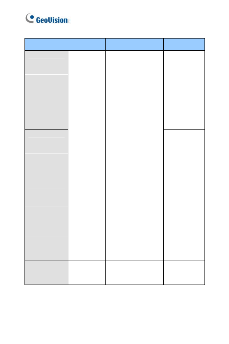
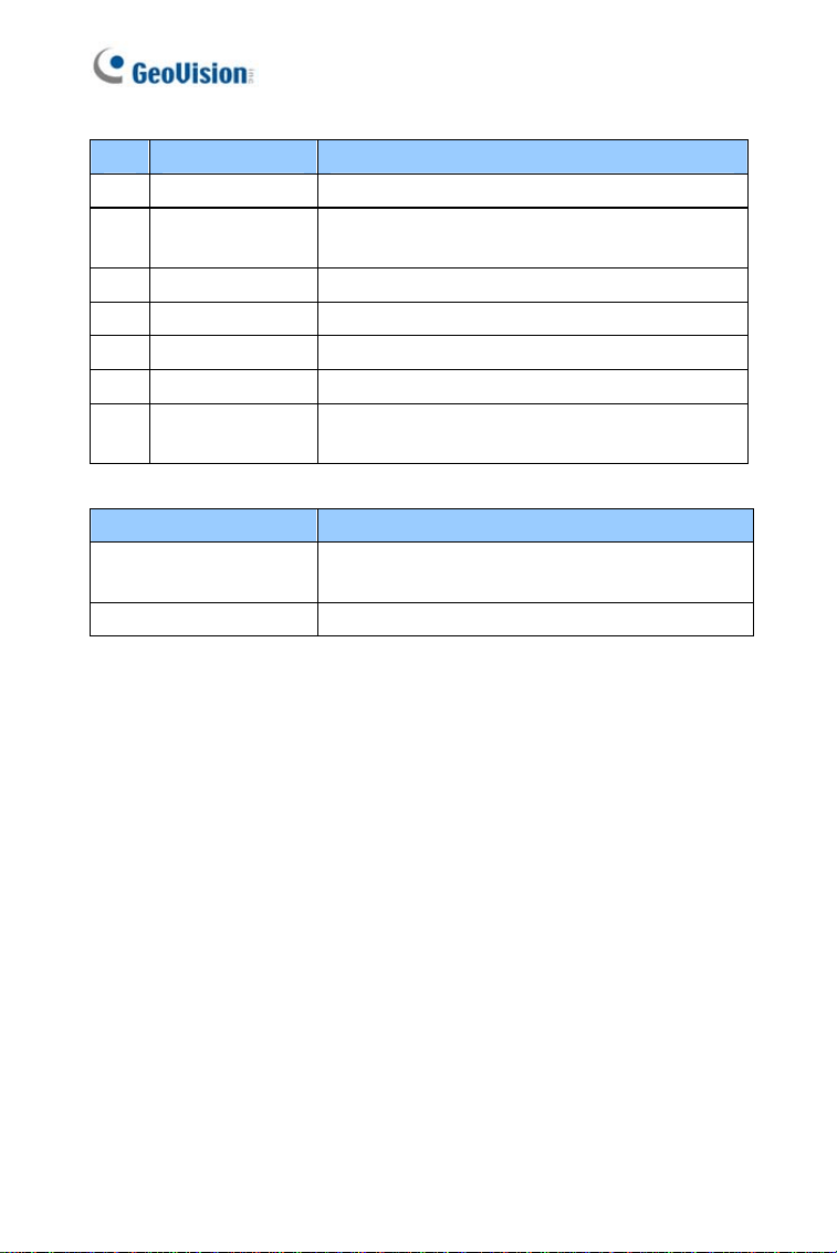
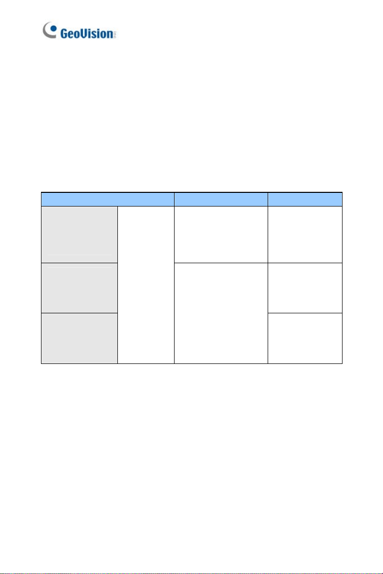
Options
Optional devices can expand your camera’s capabilities and versatility.
Contact your dealer for more information.
Device Description
Power Adapter
The power adapter is available for all Box Camera,
Ultra Box Camera, and Target Box Camera. Contact
your sales representative for the countries and areas
supported.
GV-PA191 PoE
Adapter
The GV-PA191 PoE adapter is designed to provide
power and network connection to the cameras over
a single Ethernet cable.
GV-PA482 PoE
Adapter
The GV-PA482 PoE adapter is designed to provide
power and network connection to GV-BX1500-E /
2400-E / 2510-E / 3400-E / 5300-E / 4700-E / 5310-
E over a single Ethernet cable.
GV-POE Switch
The GV-POE Switch is designed to provide power
along with network connection for IP devices. The
GV-POE Switch is available in various models with
different numbers and types of ports.
GV-Mount
Accessories
The GV-Mount Accessories provide a
comprehensive lineup of accessories for installation
on ceiling, wall corner and pole. For details, see GV-
Mount Accessories Installation Guide.
vi

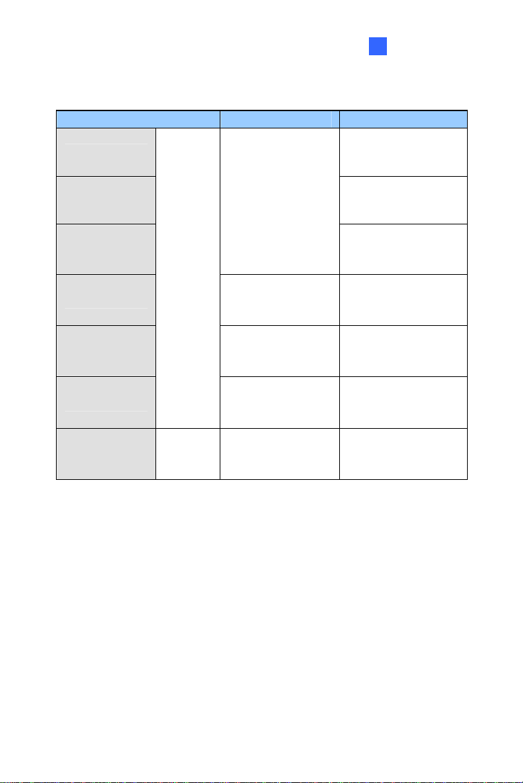
Device Description
GV-WiFi Adapter
The GV-WiFi Adapter is a plug-and-play device
designed to connect your camera to to wireless
network. The product complies with IEEE 802.11
b/g/n (Draft 3.0) standards for wireless networking.
Note: Only compatible models and firmware
versions can support GV-WiFi Adapter.
GV-Relay V2
The GV-Relay V2 is designed to expand the voltage
load of GV IP devices. It provides 4 relay outputs,
and each can be set as normally open (NO) or
normally closed (NC) independently as per your
requirement.
vii
Creating GV-IP Camera’s Login
Credentials
The default Administrator and Guest accounts are no longer supported by
GV-IPCAM H.265 series firmware V1.14 or later. When purchasing a
new camera or performing factory resetting, you need to set up a login
username and password for the camera.
1. Download and install GV-IP Device Utility from the company
website.
2. On the GV-IP Device Utility window, click
to search for your GV-
IP camera.
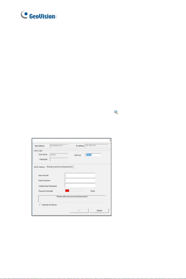
3. Double-click your GV-IP camera in the GV-IP Device Utility list. This
dialog box appears.
4. Click the Change Username and Password tab to type a new
username and password. Note that the new password must meet
the password strength requirements.
5. Optionally click Upgrade all devices to use the same username
and password on all other devices.
viii
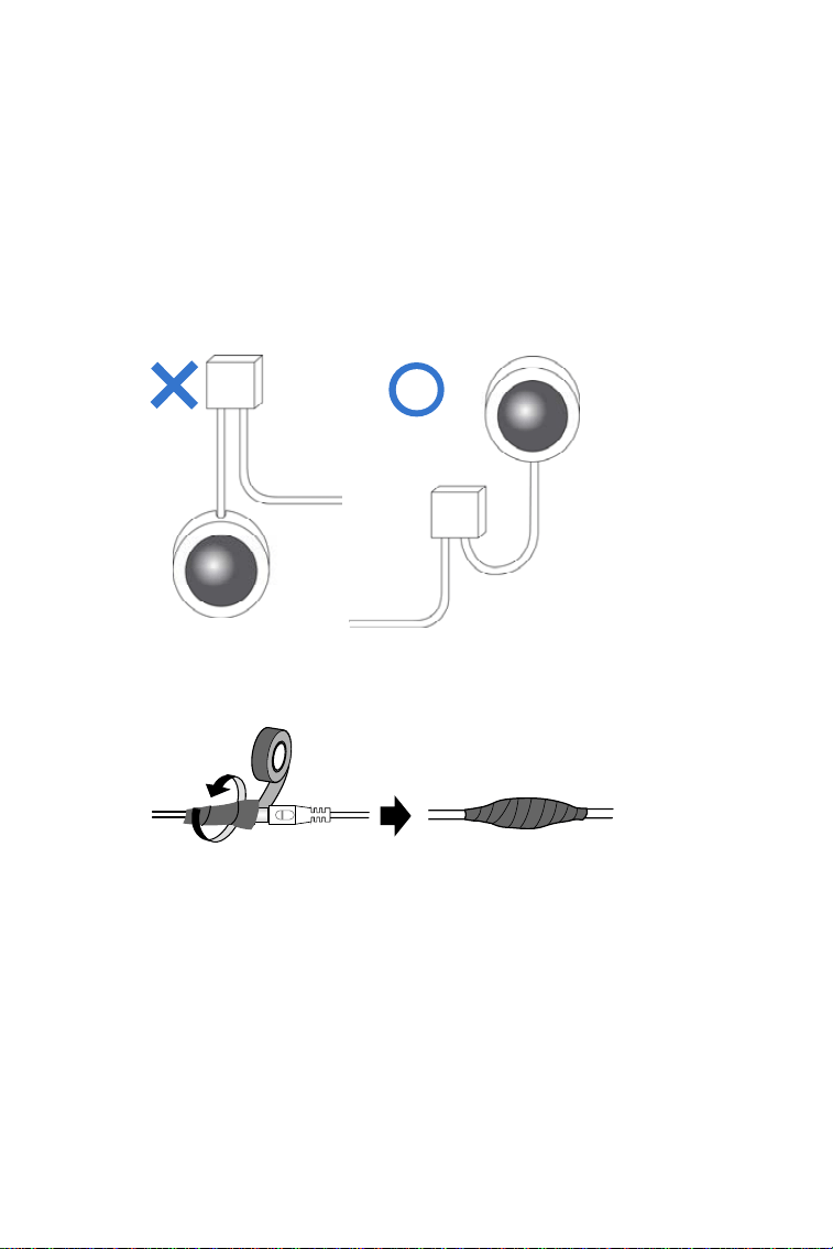
Note for Installing Camera Outdoor
When installing the IR Arctic Box Camera outdoor, be sure that:
1. The camera is set up above the junction box to prevent water from
entering the camera along the cables.
2. Any PoE, power, audio and I/O cables are waterproofed using
waterproof silicon rubber or the like.
3. The silica gel bag loses its effectiveness when the dry camera is
opened. To prevent the lens from fogging up, replace the silica gel
bag every time you open the camera, and conceal the gel bag in
camera within 2 minutes of exposing to open air.
ix

x
Note for USB Storage and WiFi
Adapter
Mind the following limitations and requirements for using USB storage and
GV-WiFi Adapter:
1. The USB hard drive must be of 2.5’’ or 3.5’’, version 2.0 or above.
2. The USB hard drive’s storage capacity must not exceed 2TB.
3. USB flash drives and USB hubs are not supported.
4. External power supply is required for the USB hard drive.
5. To connect a GV-WiFi Adapter, make sure it is connected before the
camera is powered on.
Note for Silica Gel Bags
1. The silica gel bag loses its effectiveness when the dry camera is
opened. To prevent the lens from fogging up, replace the silica gel
bag every time you open the camera, and conceal the gel bag in
camera within 2 minutes of exposing to open air.
2. When the camera is shipped, a silica gel bag will be included inside
the camera. For the first-time user, replace the silica gel bag prior to
the installation to avoid foggy live view.

Box Camera
1
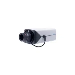
Chapter 1 Box Camera
The Box Camera is a series of indoor IP cameras consisting of fixed focal
and varifocal models in different resolutions. The Box Camera supports
lens replacement and features an automatic infrared-cut filter for day and
night surveillance. The super low lux models are capable of displaying
color live view in near darkness. Models equipped with a mini USB port
can be connected wirelessly through a GV-WiFi Adapter (optional). The
WDR Pro models can produce clear image for scenes with contrasting
intensity of lights. Models using P-Iris allow for precise control of exposure,
producing images with better clarity and contrast. The Box Camera models
are detailed below:
Box Camera
Model No. Specifications Description
GV-BX120D
Auto Iris, f:2.8 ~ 12
mm, F/1.4, 1/3” CS
Lens
1.3 MP, H.264,
Low Lux, D/N
GV-BX130D-0
Varifocal
Lens
Auto Iris, f: 2.8 ~ 12
mm, F/1.4, 1/3’’ CS
Lens
1.3 MP, H.264,
D/N
GV-BX130D-1 Fixed Lens
Fixed Iris, f: 4 mm,
F/1.4, 1/3’’ CS Lens
1.3 MP, H.264,
D/N
GV-BX140DW
Fixed Iris, f: 2.8 ~ 12
mm, F/1.4, 1/3’’ CS
Lens
1 MP, H.264,
D/N, WDR Pro
GV-BX220D-2
Varifocal
Lens
Auto Iris, f: 2.8 ~ 6
mm, F/1.3, 1/3’’ CS
Lens
2 MP, H.264,
D/N
1
Model No. Specifications Description
GV-BX220D-3
Varifocal
Lens
Auto Iris, f: 2.8 ~ 12
mm, F/1.4, 1/3’’ CS
Lens
2 MP, H.264,
D/N
GV-BX320D-0
Auto Iris, f:3.1 ~ 8
mm, F/1.2, 1/3” CS
Lens
GV-BX320D-1
Auto Iris, f: 2.8 ~ 6
mm, F/1.3, 1/3’’ CS
Lens
3 MP, H.264,
D/N
GV-BX520D
Varifocal
Lens
Manual Iris, f: 4.5 ~
10 mm, F/1.6, 1/2’’
CS Lens
5 MP, H.264,
D/N
GV-BX1200-0F
1.3 MP, H.264,
Low Lux, D/N
GV-BX1300-0F
Fixed Lens
Fixed Iris, f: 4 mm,
F/1.5, 1/3’’ CS Lens
1.3 MP, H.264,
D/N
GV-BX1200-1F
1.3 MP, H.264,
Low Lux, D/N
GV-BX1300-1F
1.3 MP, H.264,
D/N
GV-BX1500-1F
1.3 MP, H.264,
Super Low
Lux, D/N
GV-BX2400-1F
2 MP, H.264,
D/N, WDR Pro
GV-BX2500-1F
2 MP, H.264,
Super Low
Lux, D/N
GV-BX3400-1F
Fixed Lens
Fixed Iris, f: 8 mm,
F/1.6, 1/2.5’’ CS
Lens
3 MP, H.264,
D/N, WDR Pro
2

Box Camera
1
Model No. Specifications Description
GV-BX1200-2F
1.3 MP, H.264,
Low Lux, D/N
GV-BX1300-2F
1.3 MP, H.264,
D/N
GV-BX1500-2F
1.3 MP, H.264,
Super Low
Lux, D/N
GV-BX2400-2F
2 MP, H.264,
D/N, WDR Pro
GV-BX2500-2F
2 MP, H.264,
Super Low
Lux, D/N
GV-BX3400-2F
Fixed Lens
Fixed Iris, f: 12 mm,
F/1.6, 1/2.5’’ CS
Lens
3 MP, H.264,
D/N, WDR Pro
GV-BX1200-3V
1.3 MP, H.264,
Low Lux, D/N
GV-BX1300-3V
1.3 MP, H.264,
D/N
GV-BX1500-3V
1.3 MP, H.264,
Super Low
Lux, D/N
GV-BX2500-3V
Auto Iris, f:2.8 ~ 12
mm, F/1.4, 1/2.7” CS
Lens
2 MP, H.264,
Super Low
Lux, D/N
GV-BX2600
Auto Iris, f:3 ~ 10.5
mm, F/1.4, 1/2.7” CS
Lens
2 MP, H.264,
Super Low
Lux, D/N,
WDR Pro
GV-BX3400-5V
Varifocal
Lens
Auto Iris, f: 2.8 ~ 6
mm, F/1.3, 1/3’’ CS
Lens
3 MP, H.264,
D/N, WDR Pro
3
Model No. Specifications Description
GV-BX5300-6V
Varifocal
Lens
Auto Iris, f: 4.5 ~ 10
mm, F/1.6, 1/2’’ CS
Lens
5 MP, H.264,
D/N
GV-BX1500-8F
1.3 MP, H.264,
Super Low
Lux, D/N
GV-BX2500-8F
2 MP, H.264,
Super Low
Lux, D/N
GV-BX3400-8F
3 MP, H.264,
D/N, WDR Pro
GV-BX5300-8F
Fixed Iris, f: 2.8 mm,
F/1.8, 1/2.5’’ CS
Lens
5 MP, H.264,
D/N
GV-BX4700-8F
Fixed Iris, f: 2.8 mm,
F/1.8, 1/2.5’’ CS
Lens
4 MP, H.265,
Super Low
Lux, D/N,
WDR Pro
GV-BX2700-8F
Fixed Iris, f: 2.8 mm,
F/1.8, 1/2.5’’ CS
Lens
2 MP, H.265,
Super Low
Lux, D/N,
WDR Pro
GV-BX5700-8F
Fixed Lens
Fixed Iris, f: 2.95
mm, F/2.0, 1/1.8’’ CS
Lens
5 MP, H.265,
Low Lux, D/N,
WDR
GV-BX12201
Varifocal
Lens
DC drive Iris, f: 4.1 ~
9 mm, F/1.6, 1/1.8”
CS Lens
12 MP, H.264,
D/N
4
Box Camera
1
P-Iris Models
Model No. Specifications Description
GV-BX1500-3V
1.3 MP, H.264,
Super Low Lux, D/N
GV-BX2500-3V
2 MP, H.264, Super
Low Lux, D/N
GV-BX3400-3V
P-Iris, f: 3 ~ 10.5
mm, F/1.4, 1/2.5”
CS Lens
3 MP, H.264, D/N,
WDR Pro
GV-BX2700-3V
P-Iris, f: 3 ~ 10.5
mm, F/1.4, 1/2.7”
CS Lens
2 MP, H.265, Super
Low Lux, D/N, WDR
Pro
GV-BX4700-3V
P-Iris, f: 3 ~ 10.5
mm, F/1.4, 1/2.7”
CS Lens
4 MP, H.265, Super
Low Lux, D/N, WDR
Pro
GV-BX5300-6V
Varifocal
Lens
P-Iris, f: 3.3 ~ 10.5
mm, F/1.4, 1/2.5’’
CS Lens
5 MP, H.264, D/N
GV-BX5700-3V
P-Iris, f: 3.6 ~ 10
mm, F/1.5, 1/1.8”
CS Lens
5 MP, H.265, Low
Lux, D/N, WDR
5

1.1 Packing List
1.1.1 For H.265 Cameras
• Box Camera
• Terminal Block (2-Pin and 3-Pin)
• Fixed Focal or Varifocal Megapixel Lens
• Six Lens Rings (only for Varifocal Lens)
• Video Out Wire
• Camera Holder
• Holder Screw x 2
• Download Guide
• Warranty Card
6

Box Camera
1
1.1.2 For H.264 Cameras
• Box Camera
• Terminal Block (2-Pin and 3-Pin)
• Fixed Focal or Varifocal Megapixel Lens
• Six Lens Rings (only for Varifocal Lens)
• Video Out Wire
• Camera Holder
• Holder Screw x 2
• Power Adapter
• Download Guide
• Warranty Card
Note: The power adapter can be excluded upon request.
7
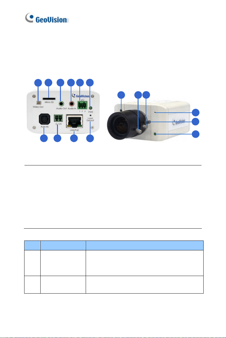
1.2 Overview
1.2.1 GV-BX120D / 130D Series / 140DW / 220D Series /
Series / 520D 320D
1
2 3 4 5 6
7 8 9
10
12
13
14
16
15
11
Figure 1-1
Note:
1. The Auto Iris connector (No. 7) is only functional in GV-BX120D,
GV-BX130D-0, GV-BX220D and GV-BX320D.
2. The Light Sensor (No.11) is only available in GV-BX140DW. Keep
the Light Sensor unobscured for accurate light detection.
3. The Iris Screw (No.13) is only available for GV-BX520D.
4. The Zoom Screw (No. 15) is not available for GV-BX130D-1.
No. Name Description
1 Video Out
Connects to a portable monitor for setting the
focus and angle of Box Camera during initial
installation.
2
Memory Card
Slot
Inserts a micro SD card (SD/SDHC, version
2.0 only, Class 10) to store recording data.
8

Box Camera
1
No. Name Description
3 Audio Out Connects a speaker for audio output.
4 Audio In Connects a microphone for audio input.
5
I/O Terminal
Block
For details, see 1.5 I/O Terminal Block.
6 Power LED
Indicates the power is supplied. For detail, see
the table below.
7
Auto Iris
Connector
Plug the iris control cable to the connector.
8 DC 12V Port Connects to power.
9 LAN / PoE Connects to a 10/100 Ethernet or PoE.
10 Default
Restores the camera to the factory default. For
details, see 1.6 Loading Factory Default.
11 Light Sensor
Detects light to switch between day and night
mode.
12 Focus Screw Adjusts the focus of the camera.
13 Iris Screw Adjusts the iris of the camera.
14 Microphone Records the sounds.
15 Zoom Screw Adjusts the zoom of the camera.
16 Status LED
Turns on when the unit is ready for use. For
detail, see the table below.
LED Description
Power LED turns green
The system powers on and succeeds to boot
up.
Status LED turns green The system is ready for use.
9
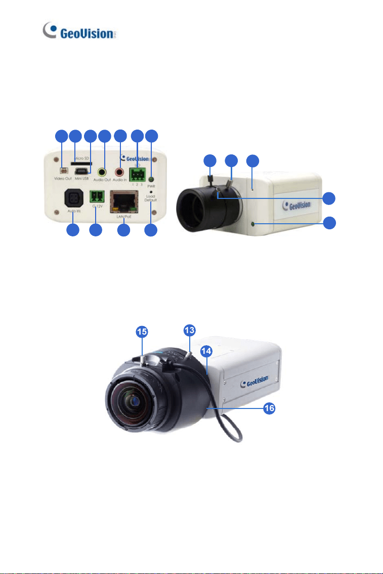
1.2.2 GV-BX1200 Series / 1300 Series / 1500 Series /
2400 Series / 2500 Series / 2600 / 2700 Series /3400
Series / 4700 Series / 5300 Series / 5700 Series / 12201
1 2 4
5
6 7
8 9
10
3
11
12 13
14
16
15
Figure 1-2-1 Figure 1-2-2:
GV-BX1200 Series / 1300 Series / 1500
Series / 2400 Series / 2500 Series / 2600
/ 2700 Series / 3400 Series / 4700 Series
/ 5300 Series / 5700 Series
Figure 1-2-1:
GV-BX12201
10

Box Camera
1
Note:
1. The Auto Iris Connector (No. 8) is only functional for the models
with auto iris lens.
2. The Iris Screw (No. 12) is only available in GV-BX5300-6V.
3. The Zoom Screw (No. 13) doesn’t work on the models with fixed
lens.
4. The Memory Card Slot (No. 2) is currently not supported for GV-
BX12201.
5. Mini USB Slot (No. 3) connected to USB hard drive is currently not
supported for GV-BX12201.
6. Built-in microphone is not available for GV-BX2600.
No. Name Description
1 Video Out
Connects to a portable monitor for setting the
focus and angle of Box Camera during initial
installation.
2
Memory Card
Slot
Inserts a micro SD card (SD/SDHC, version
2.0 only, Class 10) to store recording data.
3 Mini USB Slot
Connects to a GV-WiFi Adapter or a USB
hard drive.
4
Audio Out Connects a speaker for audio output.
5 Audio In Connects a microphone for audio input.
6
I/O Terminal
Block
Connects to I/O devices. For details, see 1.6
I/O Terminal Block.
7 Power LED
Indicates the power is supplied. For detail,
see the table below.
8
Auto Iris
Connector
Plug the iris control cable to the connector.
9 DC 12V Port Connects to power.
11
No. Name Description
10 LAN / PoE Connects to a 10/100 Ethernet or PoE.
11 Default
Restores the camera to factory default. For
details, see 1.7 Loading Factory Default.
12 Iris Screw Adjusts the iris of the camera.
13 Zoom Screw Adjusts the zoom of the camera.
14 Microphone Records the sounds.
15 Focus Screw Adjusts the focus of the camera.
16 Status LED
Turns on when the unit is ready for use. For
detail, see the table below.
LED Description
Power LED turns green
The system powers on and succeeds to boot
up.
Status LED turns green The system is ready for use.
12
Box Camera
1
1.3 Connecting the Camera
The Box Camera is designed for indoor use. Please make sure the
installing site is shielded from rain and moisture.
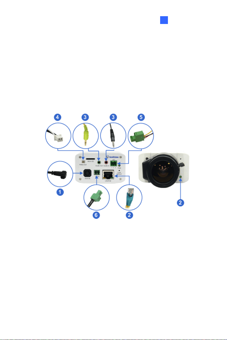
1.3.1 GV-BX120D / 130D Series / 140DW / 220D Series /
Series / 520D 320D
Figure 1-3
1. If you are using an auto iris model, plug the iris control cable to the
Auto Iris Connector on the camera.
2. Use a standard network cable to connect the camera to your network.
3. Optionally connect a speaker and an external microphone.
4. Optionally connect a monitor using a Video Out wire. Enable this
function by selecting your signal format at the
TV Out field on the
Web interface. See 4.1.1 Video Settings, GV-IPCam Firmware
Manual.
13

5. Optionally connect to input / output devices or an infrared illuminator.
For details, see 1.4.2 Infrared Illuminator and 1.5 I/O Terminal Block.
6. Connect power using one of the following methods:
• plugging the power adapter to the power port.
• using the Power over Ethernet (PoE) function and the power will
be provided over the network cable.
7. The status LED of the camera will be on.
8. You are ready to access the live view, adjust the image clarity and
configure the basics. See Getting Started, Chapter 2, GV-IPCam
Firmware Manual.
14
Box Camera
1
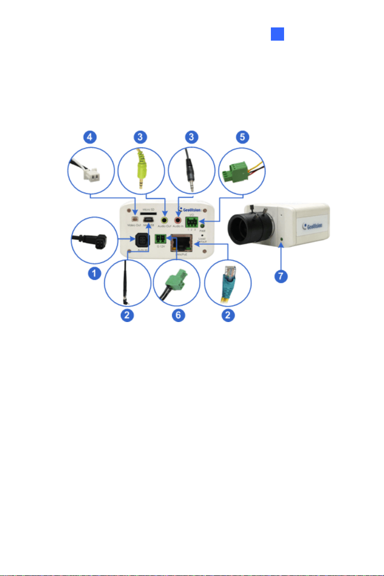
1.3.2 GV-BX1200 Series / 1300 Series / 1500 Series /
2400 Series / 2500 Series / 2600 / 2700 Series / 3400
Series / 4700 Series / 5300 Series / 5700 Series / 12201
Figure 1-4
1. If you are using an auto iris model, plug the iris control cable to the
Auto Iris Connector on the camera.
2. Connect to network using one of the following methods:
• Wired Connection: Use a standard network cable to connect the
camera to your network and optionally connect a USB hard drive
to the mini USB port.
• Wireless Connection: Connect a GV-WiFi Adapter (optional
accessory).
3. Optionally connect a speaker and an external microphone.
15

4. Optionally connect a monitor using a Video Out wire. Enable this
function by selecting your signal format at the TV Out field on the Web
interface. See 4.1.1 Video Settings, GV-IPCam Firmware Manual.
5. Optionally connect to input / output devices or an infrared illuminator.
For details, see 1.4.2 Infrared Illuminator and 1.5 I/O Terminal Block.
6. Connect power using one of the following methods:
• plugging the power adapter to the power port.
• using the Power over Ethernet (PoE) function and the power will
be provided over the network cable.
7. The status LED of the camera will be on.
8. You are ready to access the live view, adjust the image clarity and
configure the basics. See Getting Started, Chapter 2, GV-IPCam
Firmware Manual.
Note: For details on limitations and requirements of the mini USB port,
refer to the Note for USB Storage and WiFi Adapter at the beginning of
this manual.
16
Box Camera
1
1.4 Accessory Installation
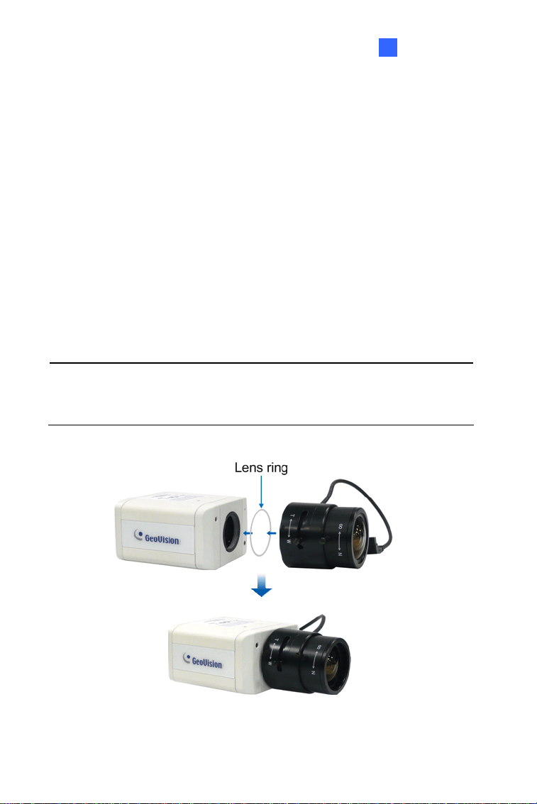
1.4.1 C-Mount Lenses
If you use a C-mount lens, it requires a certain distance from the camera’s
imaging chip to focus the lens. Mount the supplied C-mount lens adapter /
lens ring to the camera, and then secure the lens onto the camera body.
Three types of C-mount lens rings are provided for Box Camera:
• 0.188 mm (transparent color) x 2
• 0.125 mm (black color with a glossy surface) x 2
• 0.254 mm (black color with a matt surface) x 2
For GV-BX140DW, a 0.125 mm is provided.
Note: The C-mount lens rings are specially designed for Box Camera.
Besides the supplied C-mount lens rings, each of these models has
already included with the necessary lens ring.
Figure 1-5
17

1.4.2 Infrared Illuminators (Optional)
If you use an infrared (IR) illuminator with I/O function, follow the steps
below to install it.
1. Connect the infrared illuminator to the terminal block on the camera.
See 1.5 The I/O Terminal Block.
2. Access the Web interface of the camera.
3. Select
Video and Motion, select Video Settings, select Streaming 1
and set the
IR Check Function setting to Trigger by Input.
4. Click
Apply.
For details on the
Trigger by Input function, see 4.1.1 Video Settings, GV-
IPCam Firmware Manual.
18
Box Camera
1
1.5 I/O Terminal Block
The terminal block, located on the back panel of the Box Camera, provides
the interface to one input and one output devices. The I/O terminal block
can be used for applications such as motion detection, event alerts via E-
Mail and FTP, and center monitoring through Center V2 and VSM.
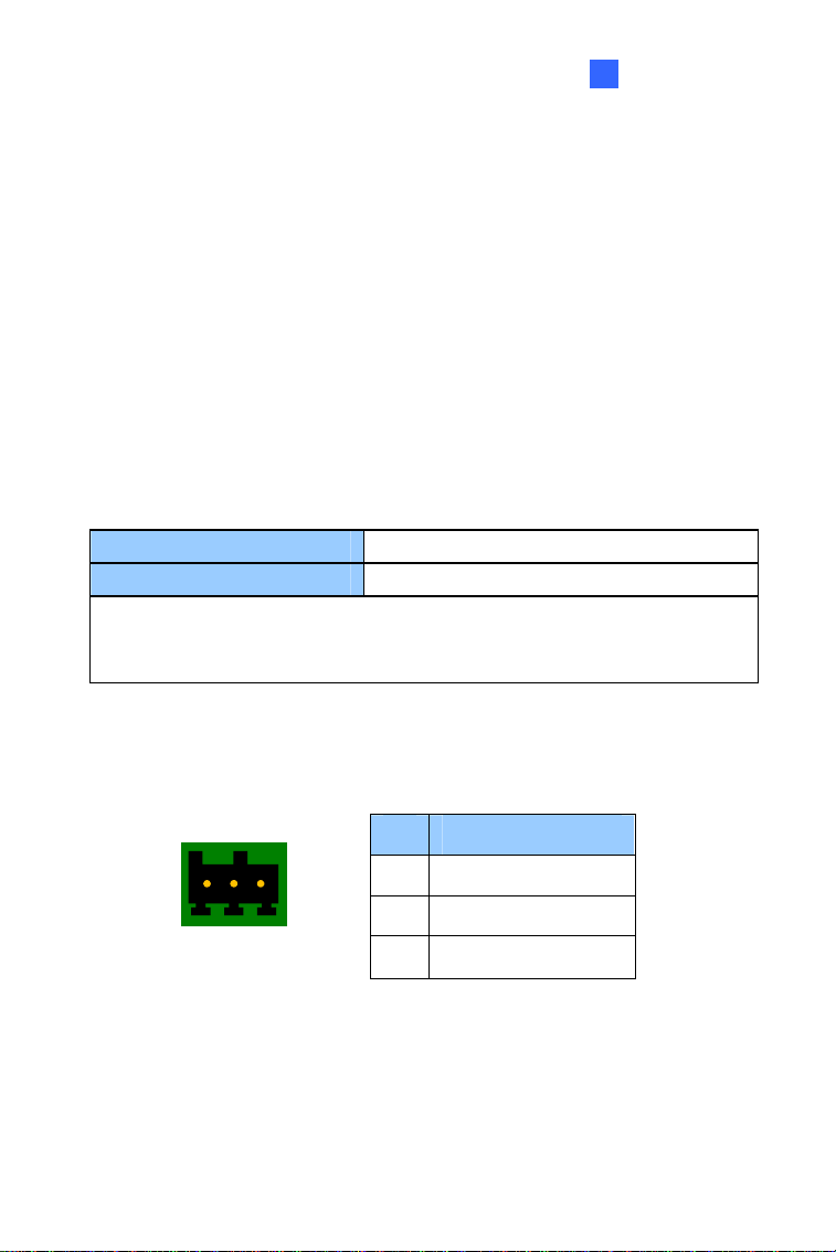
1.5.1 Pin Assignment
The pin assignment for the I/O terminal block:
For the output point, please check if your output device meets the following
Absolute Maximum Ratings before connecting it to the output point.
Breakdown Voltage 277V AC, 30V DC
Continuous Load Current 5A (NO), 3A (NC)
Note: Absolute Maximum Ratings are those values beyond which
damage to the camera may occur. Continuous operation of the camera at
the absolute rating level may affect the camera reliability.
The Box Camera support one digital input and one digital output of dry
contact.
Pin Function
1 Digital Input
2 GND
I/O
123
Figure 1-6
3 Digital Output
For details on how to enable an installed I/O device, see 4.3 I/O Settings,
GV-IPCam Firmware Manual.
19
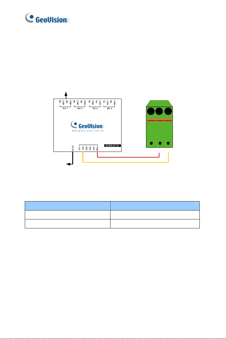
1.5.2 Connecting to GV-Relay V2 (Optional)
The Box Camera can only drive a maximum load of 200mA 5V DC. To
expand the maximum voltage load to
10A 250V AC, 10A 125V AC or 5A
100V DC
, connect the camera to a GV-Relay V2 module (optional product).
Refer to the figure and table below.
Connect to Power
Output Device
I/O
123
Figure 1-7
GV-Relay V2 I/O Terminal Block
COM Pin 2 (GND)
DO1 Pin 3 (Digital Output)
20
Box Camera
1
1.6 Loading Factory Default
You can restore factory default settings through the Web interface or
directly on the camera.
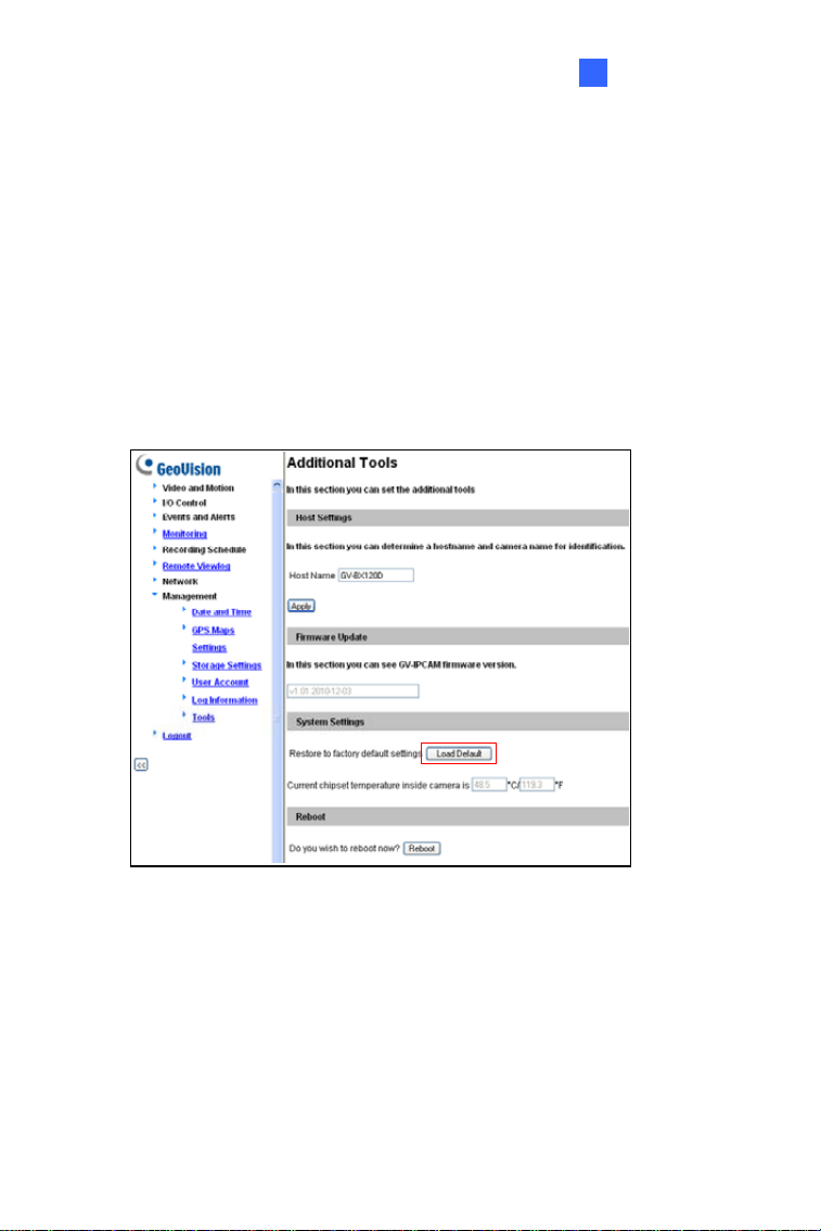
1.6.1 Using the Web Interface
1. On the left menu of Web interface, select Management and select
Tools. The Additional Tools dialog box appears.
2. Click the
Load Default button in the System Settings section.
Figure 1-8
21
22
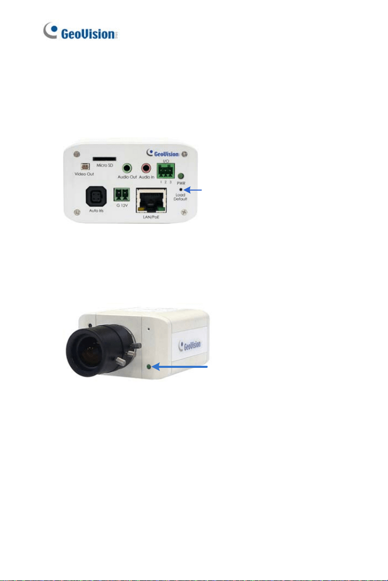
1.6.2 Directly on the Camera
1. Keep the power and network cables connected to the camera.
2. Use a pin to press and hold the
default button on the back panel of
the camera.
Default button
Figure 1-9
3. Release the default button when the status LED blinks. This shall
take about 8 seconds.
Status LED
Figure 1-10
4. When the status LED fades, the process of loading default settings is
completed and the camera reboots automatically.

IR Arctic Box Camera
2
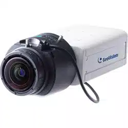
Chapter 2 IR Arctic Box Camera
The IR Arctic Box Camera is a series of outdoor cameras designed for
environments of extreme temperatures. The cameras adhere to IP67 and
IK10 protection standards, and are equipped with IR LEDs and removable
IR-cut filter for day and night surveillance. The GV-BX2400-E / 3400-E /
4700-E are equipped with WDR Pro to produce clear image for scenes
containing contrasting intensity of lights. Models using P-Iris allow for
precise control of exposure, producing images with better clarity and
contrast.
IR Arctic Box Camera
Model No. Specifications Description
GV-BX120D-E
Auto Iris, f: 2.8 ~ 12
mm, F/1.4, 1/3” CS
Lens
1.3 MP, H.264,
Low Lux, D/N
GV-BX220D-E
Auto Iris, f: 2.8 ~ 6 mm,
F/1.3, 1/3’’ CS Lens
2 MP, H.264, D/N
GV-BX320D-E
Auto Iris, f: 2.8 ~ 6 mm,
F/1.3, 1/3’’ CS Lens
3 MP, H.264, D/N
GV-BX520D-E
Manual Iris, f: 4.5 ~ 10
mm, F/1.6, 1/2’’ CS
Lens
5 MP, H.264, D/N
GV-BX1500-E
Auto Iris, f: 3 ~ 10.5
mm, F/1.4, 1/2.7’’ CS
Lens
1.3 MP, H.264,
Super Low Lux,
D/N
GV-BX2400-E
GV-BX3400-E
Auto Iris, f: 3 ~ 10.5
mm, F/1.4, 1/2.7’’ CS
Lens
2 MP / 3 MP,
H.264, D/N, WDR
Pro
GV-BX4700-E
Varifocal
Lens
Auto Iris, f: 3 ~ 10.5
mm, F/1.4, 1/2.7’’ CS
Lens
4 MP, H.265, D/N,
WDR Pro
23
Model No. Specifications Description
GV-BX5300-E Varifocal Lens
Manual Iris, f: 4.5 ~
10 mm, F/1.6, 1/2’’
CS Lens
5 MP, H.264
D/N
GV-BX2510-E
P-Iris, f: 3.7 ~ 9 mm,
F/1.2, 1/2’’, ø 14
mm mount
2 MP, H.264,
Super Low Lux,
D/N
GV-BX5310-E
Motorized
Varifocal Lens
P-Iris, f: 4.5 ~ 9 mm,
F/1.2, 1/2’’, ø 14
mm mount
5 MP, H.264
D/N
24

IR Arctic Box Camera
2
2.1 Packing List
For GV-BX120D-E / 220D-E / 320D-E / 520D-E / 1500-E / 2400-E /
3400-E / 4700-E / 5300-E
• IR Arctic Box Camera
• Screw Anchor x 4
• Screw x 4
• Washer x 4
• 4 mm Torx Wrench
• 5 mm Torx Wrench
• Silica Gel Bag x 2
• Adhesive Tape for Silica Gel Bag x 2
• Download Guide
• Warranty Card
Note: Optionally purchase a GV-PA482 PoE Adapter for GV-BX1500-E
/ 2400-E / 3400-E / 4700-E / 5300-E.
25

For GV-BX2510-E / 5310-E
• IR Arctic Box Camera
• Screw Anchor x 4
• Screw x 4
• Washer x 4
• 5 mm Torx Wrench
• Silica Gel Bag
• Adhesive Tape for Silica Gel Bag
• Power Adapter (DC 48V, 2.5A, 120 W max.)
• Download Guide
• Warranty Card
Note: Optionally purchase a GV-PA482 PoE Adapter for GV-BX2510-E
/ 5310-E.
26
IR Arctic Box Camera
2
2.2 Overview
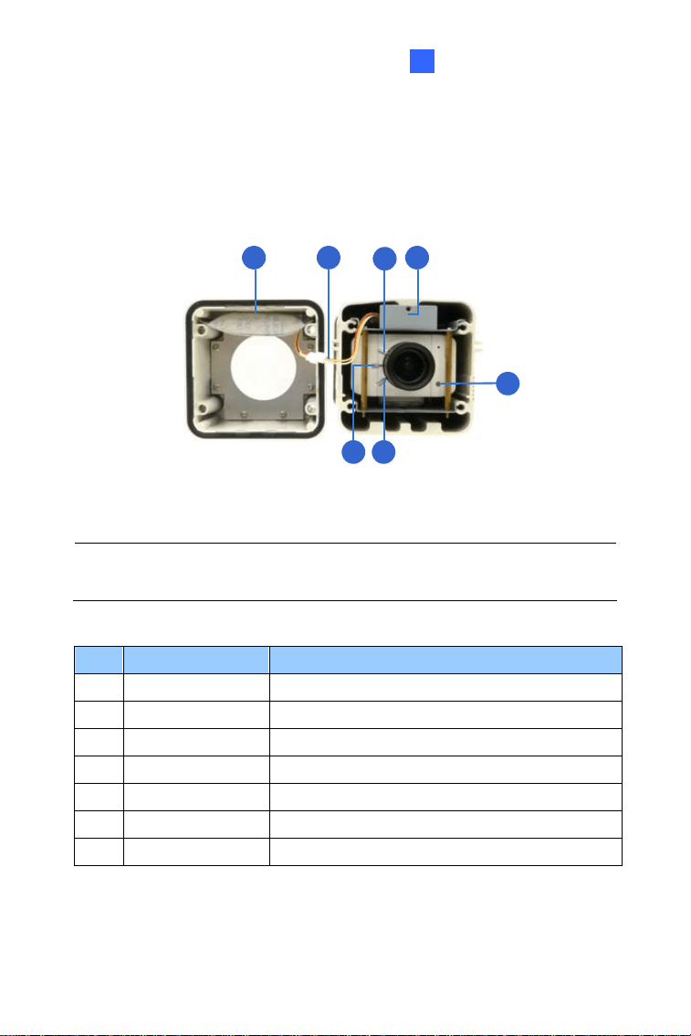
2.2.1 GV-BX120D-E / 220D-E / 320D-E / 520D-E / 1500-E /
-E / 3400-E / 4700-E / 5300-E 2400
1 2
3
4
5
7 6
Figure 2-1
Note: The Iris Screw (No. 7) is only available in GV-BX520D-E and GV-
BX5300-E.
No. Name Description
1. Silica gel bag Desiccant that keeps the camera housing dry.
2. IR power plug Supplies power to the built-in IR LEDs.
3. Focus Screw Adjusts the focus of the camera.
4. Module screw Holds the module in place.
5. Status LED Turns on when the camera is ready for use.
6. Zoom Screw Adjusts the zoom of the camera.
7. Iris Screw Adjusts the iris of the camera.
27
2.2.2 GV-BX2510-E / 5310-E
1
2
5
3
4
Figure 2-2
No. Name Description
1. Silica gel bag Desiccant that keeps the camera housing dry.
2.
Memory Card
Slot
Inserts a micro SD card (SD/SDHC, version
2.0, Class 10) to store recording data.
3. Power LED
Turns on when the camera is supplied with
power.
4. Status LED Turns on when the camera is ready for use.
5. Default
Resets all configurations to factory default. For
details, see 2.6 Loading Factory Default.
28
IR Arctic Box Camera
2
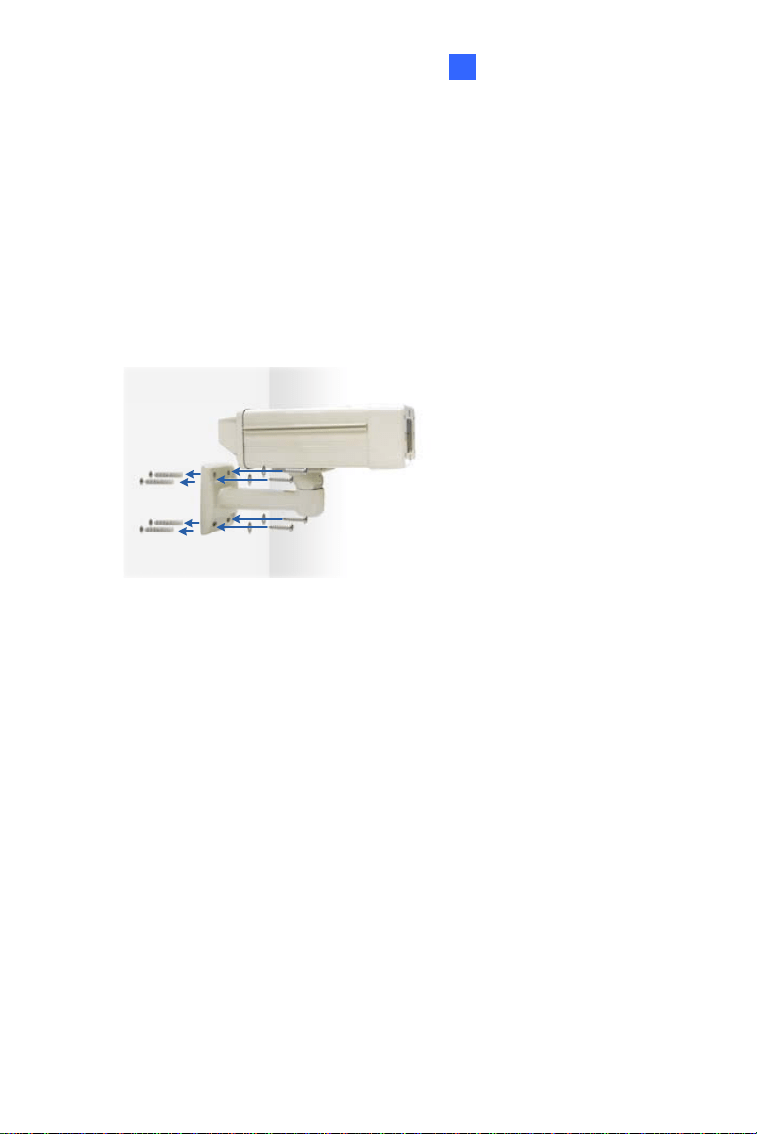
2.3 Installation
The IR Arctic Box Camera is designed for outdoor use. Follow the steps
below to install your camera.
1. Mark the installation site and drill four holes for screw anchors.
2. Insert the supplied screw anchors.
3. Secure the camera to the wall using the supplied washers and screws.
Figure 2-3
4. Connect the camera with wires and cables. See 2.4 Connecting the
Camera.
5. Access the live view. See 5.2 Accessing the Live View.
29
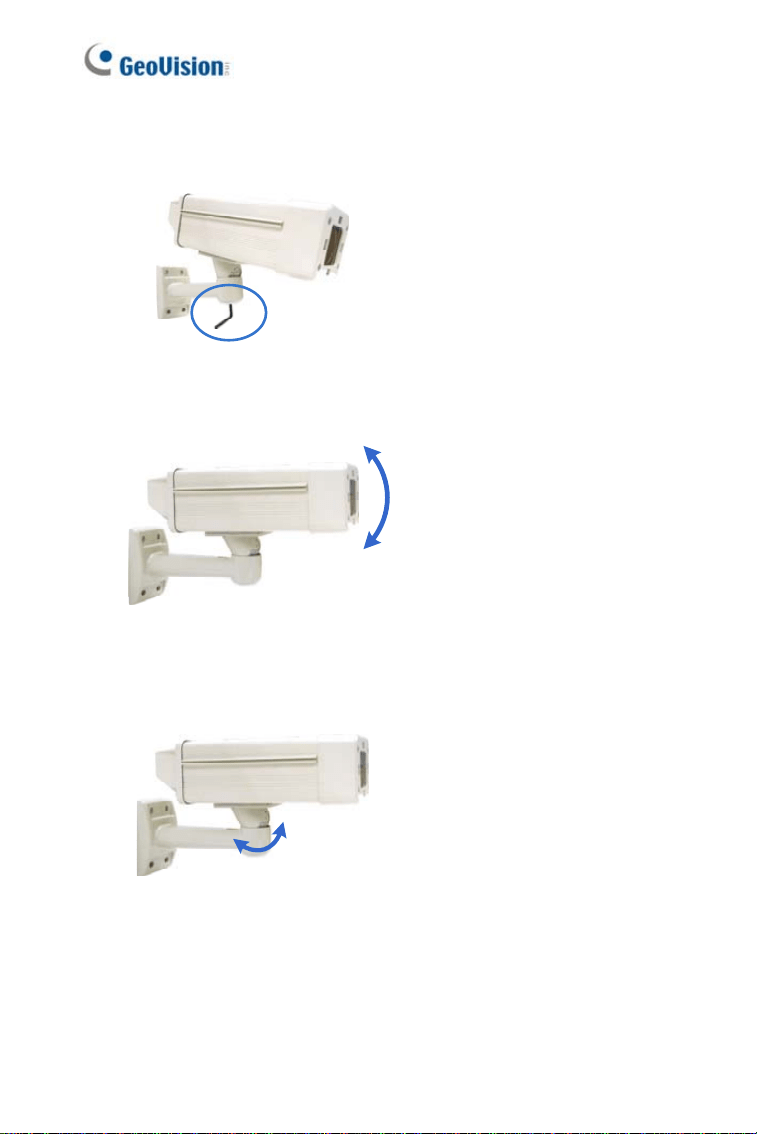
6. Based on the live view, adjust the angle of the camera. Loosen the
indicated screw with the supplied big torx wrench and adjust the joint.
Figure 2-4
Tilt Adjustment
Figure 2-5
Pan Adjustment
Figure 2-6
30
IR Arctic Box Camera
31
2
7. For GV-BX120D-E / 220D-E / 320D-E / 520D-E / 1500-E / 2400-E /
3400-E / 4700-E / 5300-E
, adjust for image clarity based on the live
view.
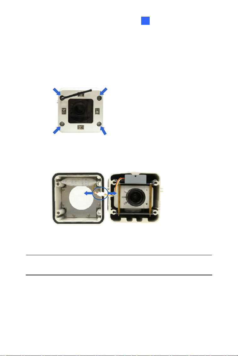
A. Unscrew the cover with the supplied 4 mm torx wrench.
Figure 2-7
B. Hold and unplug the connector.
Figure 2-8
IMPORTANT: Unscrew and remove the cover carefully. Pulling the
cover off may cause damages to the inner wiring of the camera.
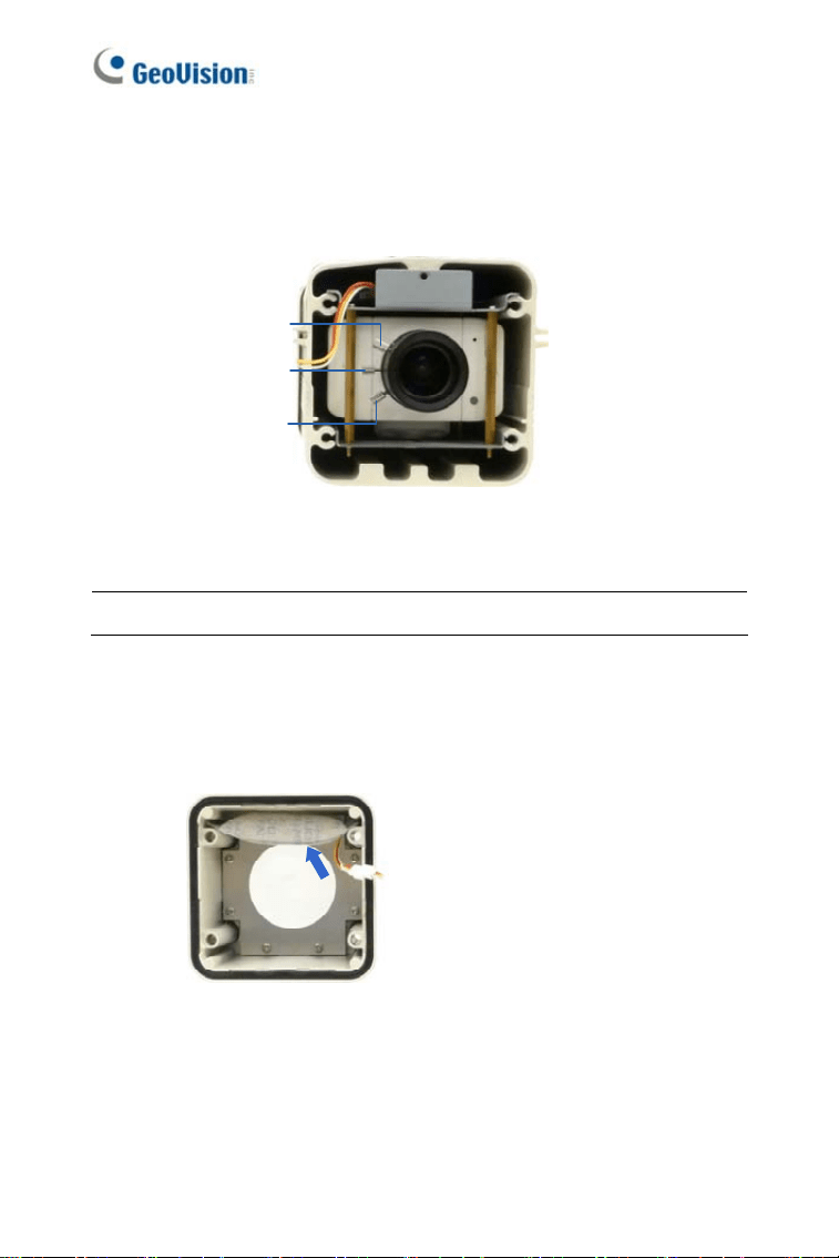
C. Adjust the focus, zoom and iris screws. For a more precise
focus, use GV-IP Device Utility. For details, see 5.3 Adjusting
Image Clarity.
Focus screw
Iris screw
Zoom screw
Figure 2-9
Note: Only GV-BX520D-E and GV-BX5300-E contain an iris screw.
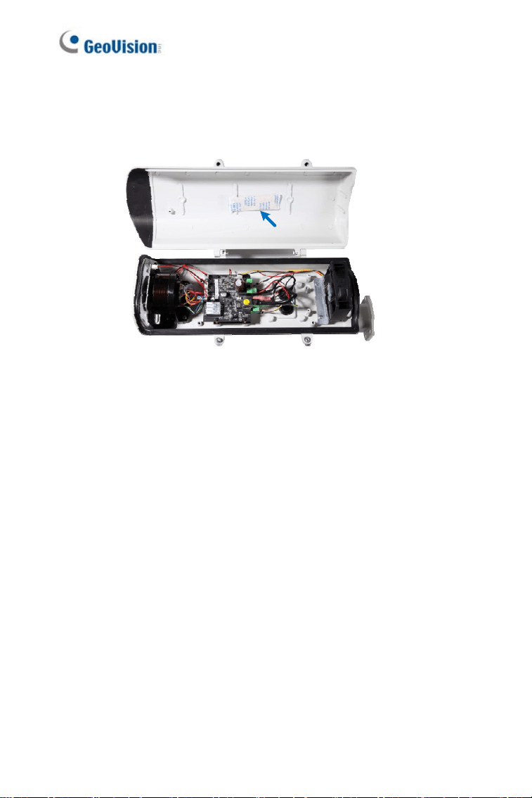
D. Replace the silica gel bag. Paste the sticker to the silica gel bag.
Press the sticker several times onto the camera cover to make
sure it adheres properly.
Figure 2-10
E. Follow steps 7B and 7A to plug the connector back and close
the camera cover.
32
IR Arctic Box Camera
2
8. For GV-BX2510-E / 5310-E, optionally insert a memory card.
A. Open the camera cover using the supplied torx wrench.
Figure 2-11
B. Insert a memory card to the card slot.
Memory card slot
Figure 2-12
33
C. Replace the silica gel bag. Paste the sticker to the silica gel bag.
Press the silica gel bag several times onto the camera cover to
make sure it adheres properly.
Figure 2-13
D. Follow step 8A to close the camera cover.
34
IR Arctic Box Camera
2
2.4 Connecting the Camera
2.4.1 GV-BX120D-E / 220D-E / 320D-E / 520D-E / 1500-E /
2400-E / 3400-E / 4700-E / 5300-E
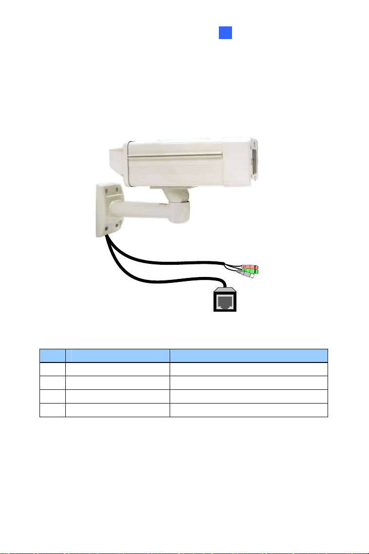
Figure 2-14
No. Wire Definition
1 RJ-45 PoE
2 Black BNC TV out
3 Green RCA Audio Out
4 Pink RCA Audio In
35

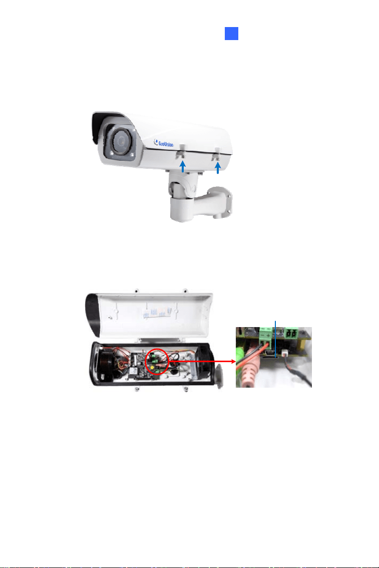
1. Optionally connect a speaker (green) and an external microphone
(pink).
2. Optionally connect a monitor using a Video Out wire. Enable this
function by selecting your signal format at the
TV Out field on the
Web interface. See 4.1.1 Video Settings, GV-IPCam Firmware
Manual.
3. Connect the camera to a GV-PA482 PoE Adapter to supply power
and network access. For detailed instruction, see step 3 of For GV-
BX25010-E / 5310-E in the next section of Chapter 2.
4. The status LED of the camera will be on.
5. You are ready to access the live view.
36
IR Arctic Box Camera
2
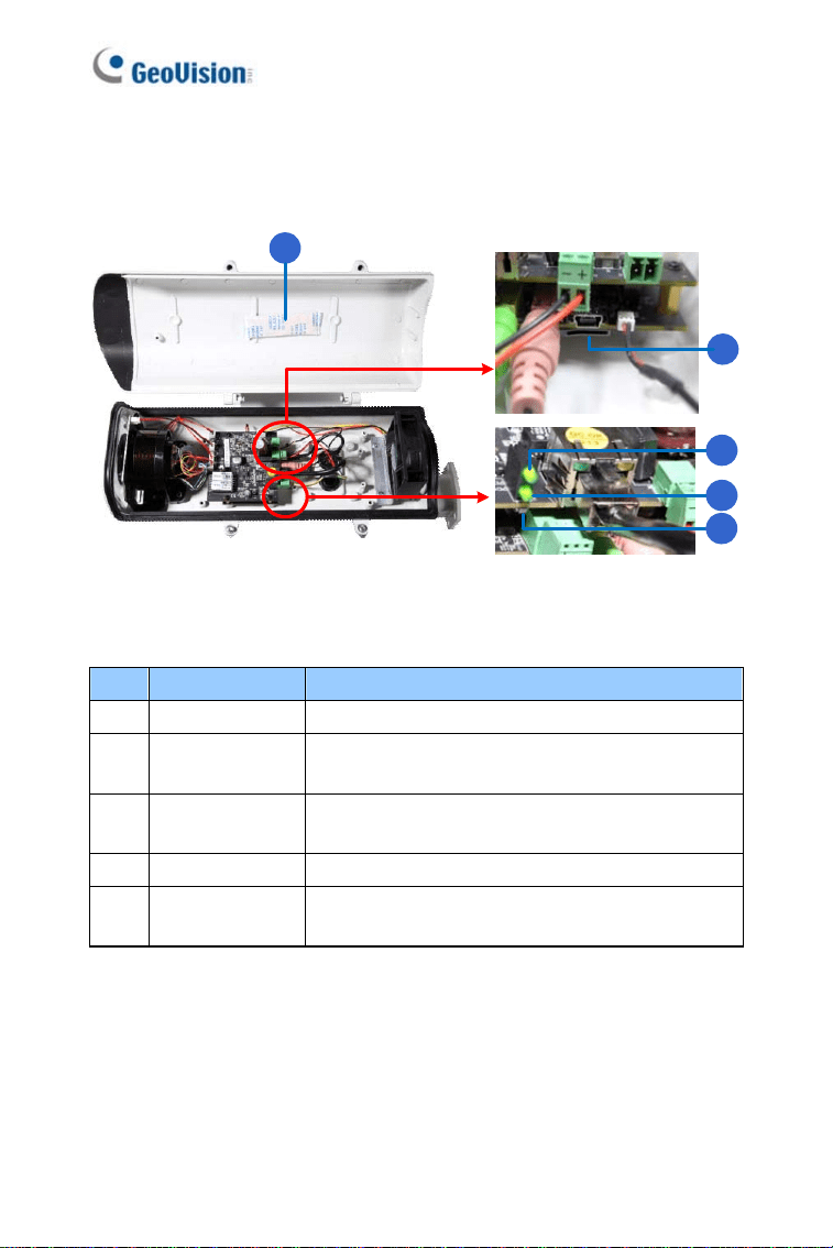
2.4.2 GV-BX2510-E / 5310-E
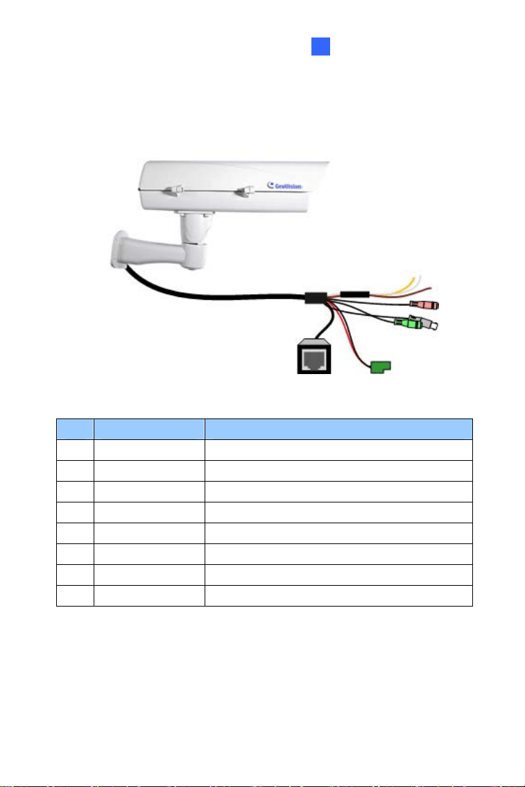
Figure 2-15
No. Wire Definition
1. Green RCA Audio Out
2. Pink RCA Audio In
3. Brown wire Digital Output
4. Yellow wire Digital Input
5. White wire GND
6. Terminal Block DC 48V
7. BNC TV Out
8. RJ-45 Ethernet/PoE
37
1. Optionally connect the audio out (green), audio in (pink), digital output
(brown), digital input (yellow), and GND.
2. Optionally connect a monitor using a Video Out wire. Enable this
function by selecting your signal format at the
TV Out field on the Web
interface. See 4.1.1 Video Settings, GV-IPCam Firmware Manual.
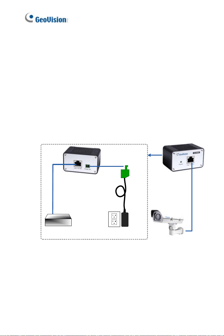
3. Supply the camera with power and network access using one of the
following methods:
• Use a GV-PA482 Power over Ethernet adapter to connect the
camera to power and network as illustrated below. GV-PA482
• PoE adapter is an optional accessory. For detail, see Options in the
manual.
DC 48V Power Adaptor
Power
Hub/Router
Ethernet Cable
Rear Panel
PoE
Figure 2-16
38
IR Arctic Box Camera
2
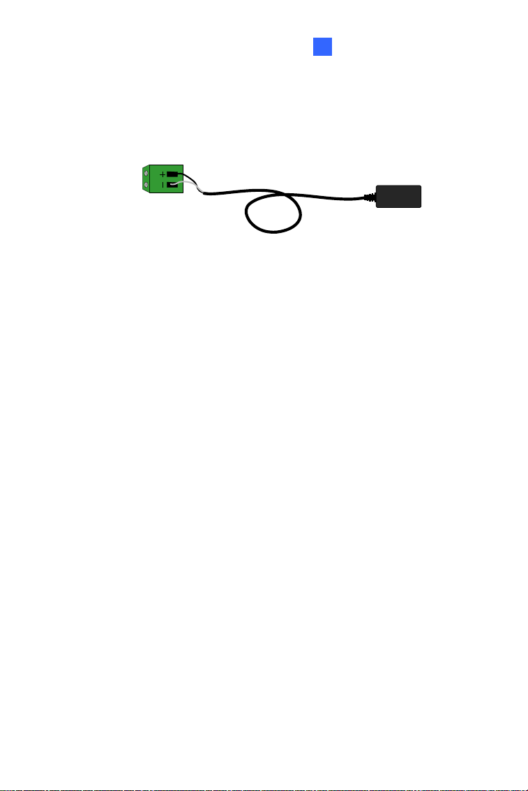
• Use the supplied power adapter. Connect the black wire of the
power adaptor to the plus (+) port and the white wire to the negative
(-) port. Connect the camera to network with a network cable.
DC 48V Power Adaptor
Terminal Block from
the Camera Cable
Figure 2-17
4. You are ready to access the live view.
39

2.5 Notice for Using the IR Arctic Box Camera
For GV-BX120D-E / 220D-E / 320D-E / 520D-E / 1500-E / 2400-E / 3400-E
/ 4700-E / 5300-E
, make sure that you:
• enable IR LED function on the Web interface after loading the default
settings.
• disable the status LED to reduce reflection when a green light spot
appears on the live view.
40
IR Arctic Box Camera
2
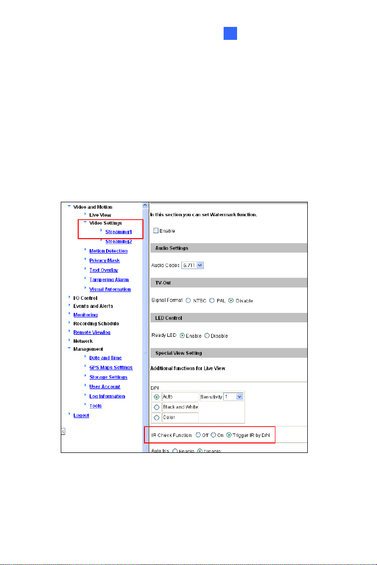
2.5.1 Enabling IR LED after Loading Default
Each GV-IR Arctic Box Camera is equipped with 4 IR LEDs to provide
infrared illumination at night. The factory-loaded setting for the IR LED
function is
enabled. If you have restored the camera to default settings,
please follow the steps below to enable the IR LED function.
1. In the left menu of Web interface, select
Video Settings and then
Streaming 1.
2. Enable
Trigger IR by D/N in IR Check Function.
Figure 2-18
3. Click
Apply.
41
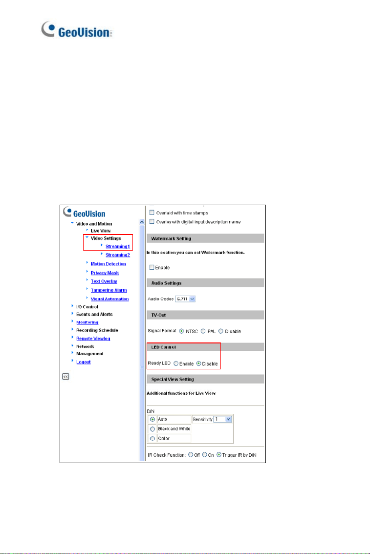
2.5.2 Disabling Status LED under Low Light Conditions
If you have a green light spot on the live view, this is likely due to
insufficient light at the installation site, which causes the status LED to
reflect on the camera cover. In this case, it is advisable that you disable the
status LED.
1. In the left menu of Web interface, select
Video Settings and then
Streaming 1.
2. Select
Disable in LED Control.
Figure 2-19
3. Click
Apply.
42
IR Arctic Box Camera
43
2
2.6 Loading Factory Default
2.6.1 Using the Web Interface
You can restore factory default settings through the Web Interface. For
details, see 1.6.1 Using the Web Interface, Loading Factory Default.
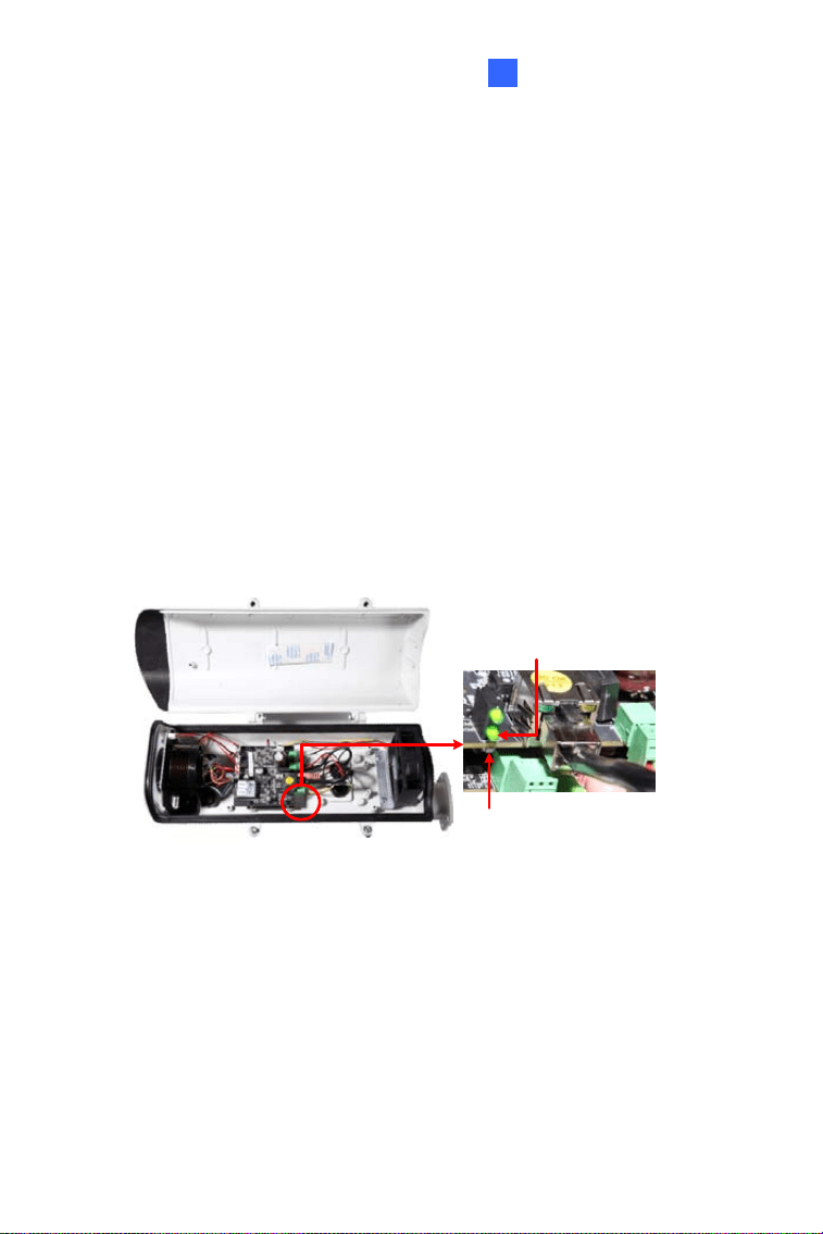
2.6.2 Directly on the Camera
Note that only GV-BX2510-E and GV-BX5310-E are equipped with a
default button.
Press and hold the
default button for about 8 seconds to restore the
factory default. After the
status LED blinks, release the default button. For
details see 1.6 Loading Factory Default.
Default button
Status LED
Figure 2-20
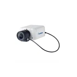
Chapter 3 Ultra Box Camera
The Ultra Box Camera is a series of light-weighted cameras designed for
indoor usage. Equipped with IR-cut filter and built-in IR LEDs, the Ultra Box
Camera provides excellent image quality. The camera supports PoE and
can be installed intuitively. Nine models of varying resolutions and focal
lengths are available.
Model No. Specifications Description
GV-UBX1301-0F
GV-UBX1301-1F
GV-UBX1301-2F
Fixed Iris, f: 2.8 mm,
F/2.0, 1/3’’ M12
Mount
1.3 MP, H.264,
D/N
GV-UBX2301-0F
GV-UBX2301-1F
GV-UBX2301-2F
2 MP, H.264,
D/N
GV-UBX3301-0F
GV-UBX3301-1F
GV-UBX3301-2F
Fixed Lens
Fixed Iris, f: 4 / 8
mm, F/1.6, 1/3’’
M12 Mount
3 MP, H.264,
D/N
44

Ultra Box Camera
3
3.1 Packing List
• Ultra Box Camera
• Supporting rack
• Screw x 3
• Screw anchor x 3
• Power Adapter
• Download Guide
• Warranty Card
Note: The power adapter can be excluded upon request.
45
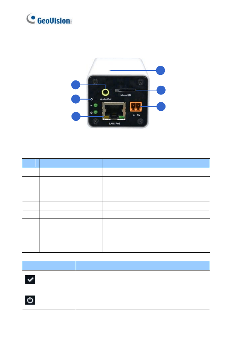
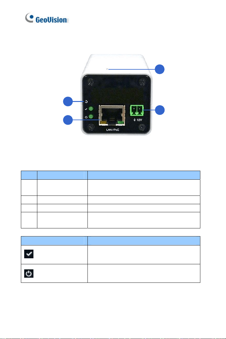
3.2 Overview
1
3
5
6
4
2
Figure 3-1
No. Name Description
1 Audio Out Connects a speaker for audio output.
2 Default
Resets the camera to factory default.
For details, see 3.5 Loading Factory
Default.
3 LAN / PoE Connects to a 10/100 Ethernet or PoE.
4 Microphone Records sounds.
5 Memory Card Slot
Inserts a micro SD card (SD/SDHC,
version 2.0 only, Class 10) to store
recording data.
6 DC 5V Terminal Block Connects to power.
LED Indicator Description
Status LED
The status LED turns on (green) when the system
is ready for use.
Power LED
The power LED turns on (green) when power is
supplied to the camera.
46

Ultra Box Camera
3
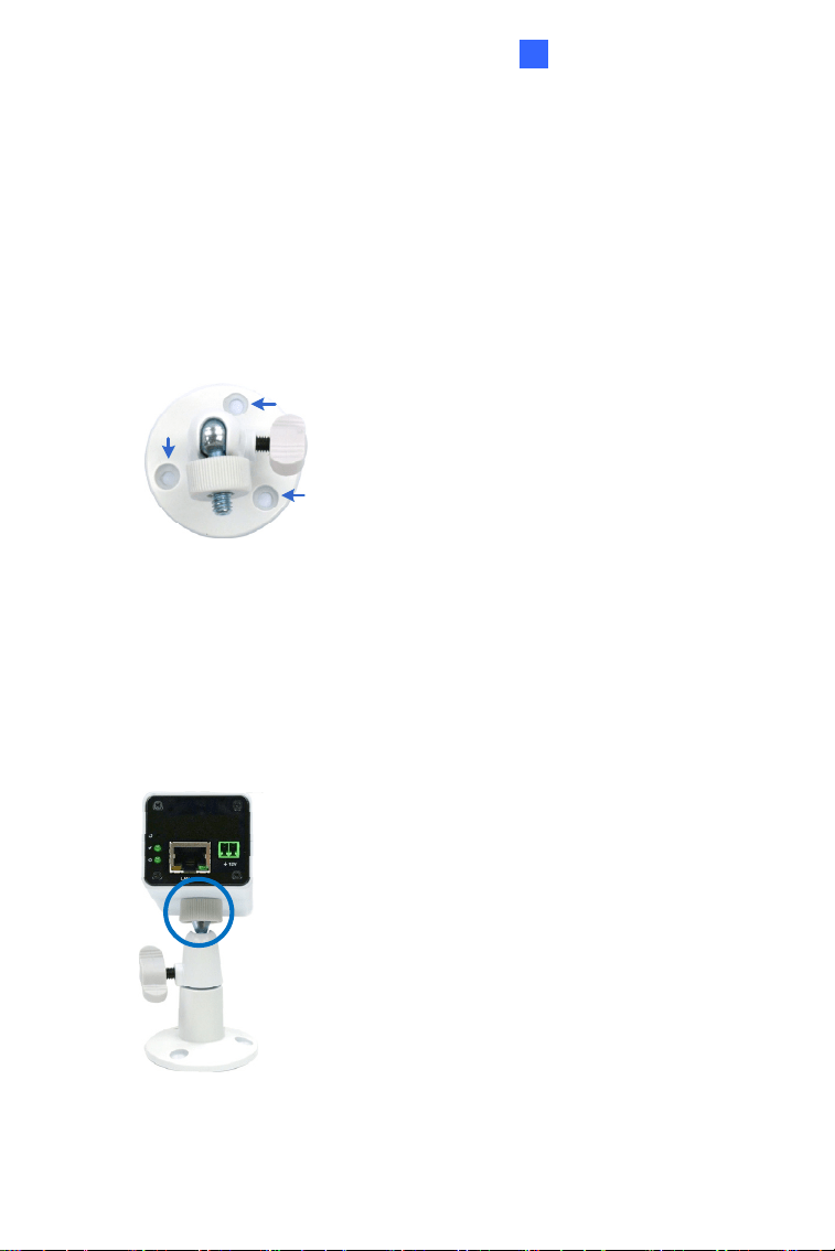
3.3 Installation
You can stand the Ultra Box Camera on a plain surface or install it to wall
and ceiling. Follow the steps below to install, connect and adjust your Ultra
Box Camera.
1. To install the device on the wall/ceiling, put the supporting rack on the
desired location and make marks for screw anchors.
Figure 3-2
2. Drill the marks and insert the screw anchors.
3. Secure the supporting rack onto the wall/ceiling using the supplied
screws.
4. Secure the camera onto the supporting rack and fasten the indicated
screw.
Figure 3-3
47

48
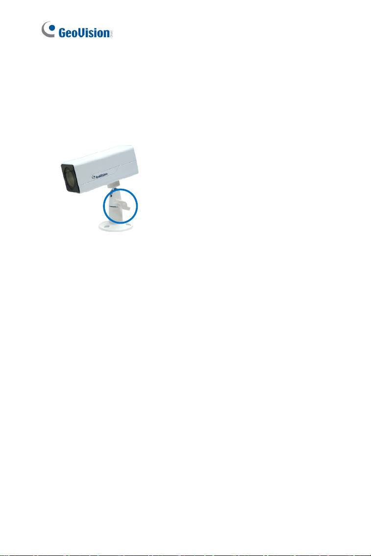
5. Connect the network and power cables to the camera. See 3.4
Connecting the Camera.
6. Access the live view. See 5.2 Accessing the Live View.
7. Adjust the angle of the camera based on live view and fasten the
indicated screw.
Figure 3-4
Ultra Box Camera
3
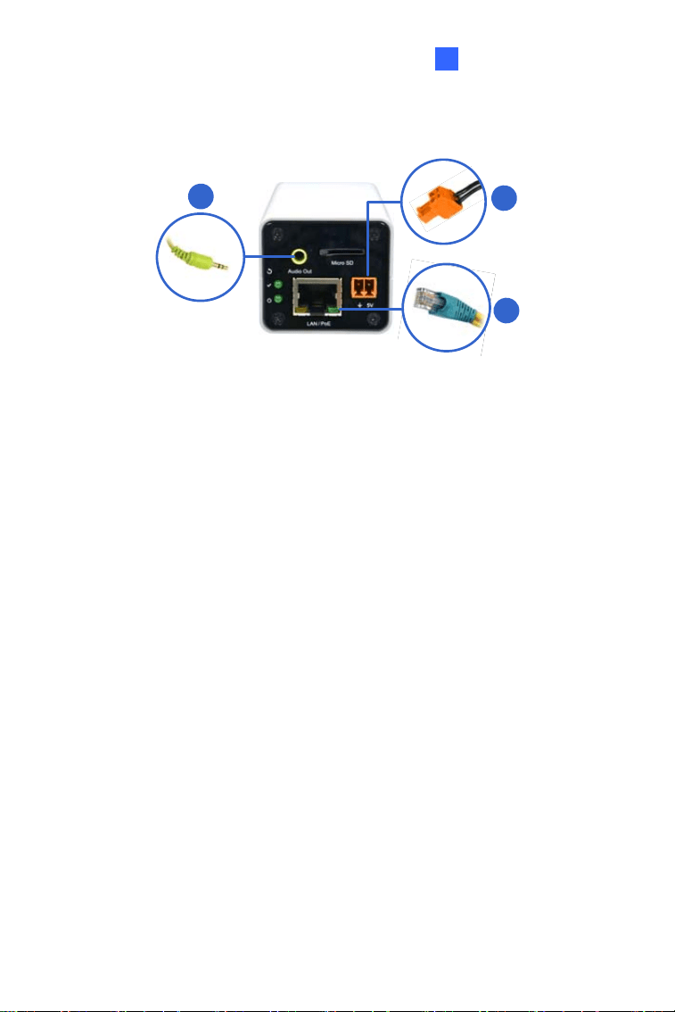
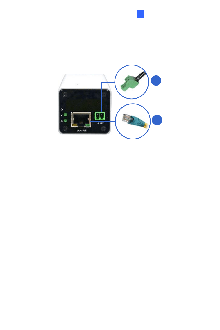
3.4 Connecting the Camera
2
3
1
Figure 3-5
1. Connect power using one of the following methods:
• Plug the power adapter to the 5V terminal block. The power
adapter is an optional device. For detail, see Options in the
manual.
• Use the Power over Ethernet (PoE) function and the power will be
provided over the network cable.
The power and status LEDs shall turn on (green).
2. Use a standard network cable to connect the camera to your network.
3. Optionally connect a speaker.
4. Insert a micro SD card (SD/SDHC, version 2.0 only, Class 10).
5. You are ready to access the live view, adjust the image clarity and
configure the basics. See Getting Started, Chapter 2, GV-IPCam
Firmware Manual.
49
50
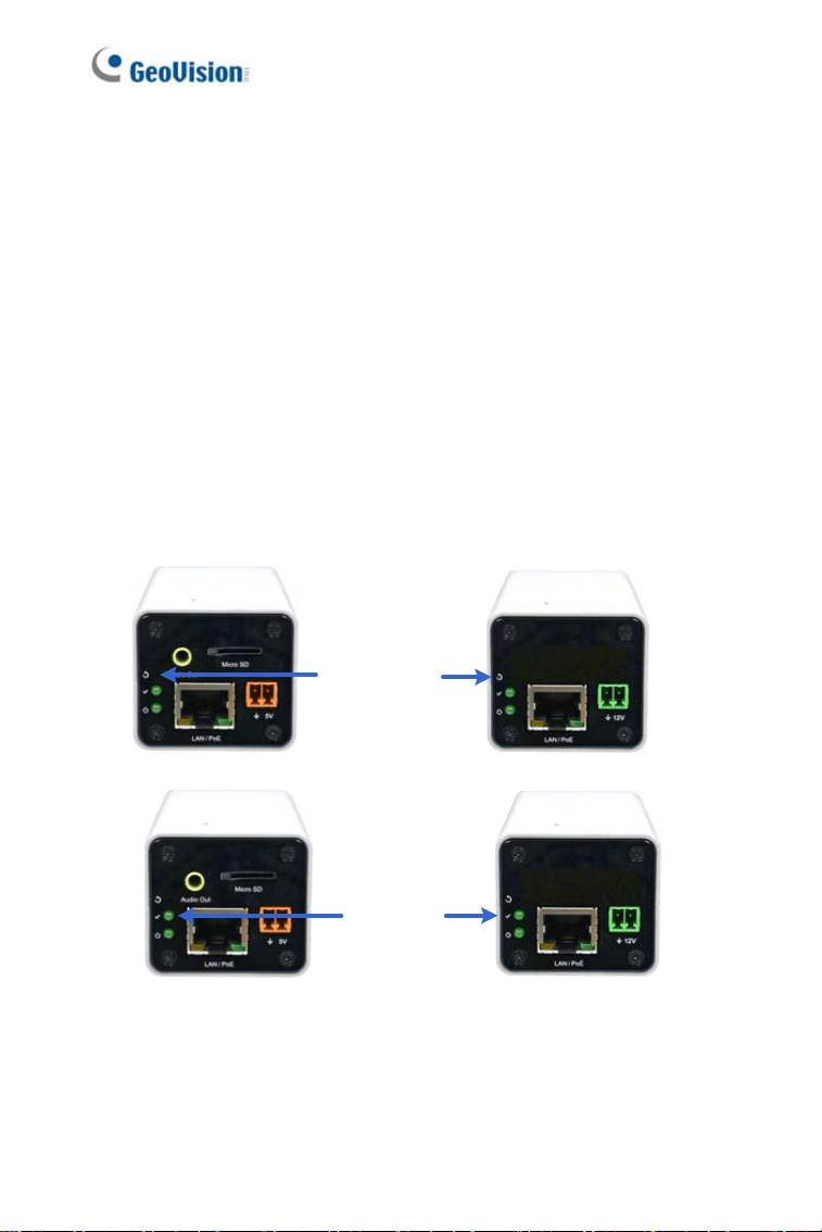
3.5 Loading Factory Default
3.5.1 Using the Web Interface
You can restore factory default settings through the Web Interface. For
details, see 1.6.1 Using the Web Interface, Loading Factory Default.
3.5.2 Directly on the Camera
Press and hold the default button for about 8 seconds to restore the
factory default. After the
status LED blinks, release the default button.
When the status LED turns on (green), the camera is ready for use. For
details see 1.6 Loading Factory Default.
Default button
Status LED
Figure 3-6

Target Box Camera
4
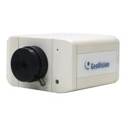
Chapter 4 Target Box Camera
The Target Box Camera (GV-EBX) is a series of light-weighted cameras
designed for indoor usage. Equipped with IRcut filter and builtin IR LEDs,
the camera is an entry-level surveillance solution with all the essential
features and excellent image quality. The camera supports PoE and can
be installed intuitively.
Model No. Iris Specifications Description
GV-EBX1100-0F
1.3 MP, H.264,
Low Lux, D/N
GV-EBX2100-0F
Fixed Iris, f: 2.8 mm,
F/2.0, 1/2.7’’ M12
Mount
2 MP, H.264,
Low Lux, D/N
GV-EBX1100-2F
1.3 MP, H.264,
Low Lux, D/N
GV-EBX2100-2F
Fixed Lens
Fixed Iris, f: 3.8 mm,
F/1.8, 1/2.7’’ M12
Mount
2 MP, H.264,
Low Lux, D/N
4.1 Packing List
• Target Box Camera
• Supporting Rack
• Screw x 3
• Screw Anchor x 3
• Download Guide
• Warranty Card
Note: Power adapter can be purchased upon request.
51
4.2 Overview
1
4
2
3
Figure 4-1
No. Name Description
1 Default
Resets the camera to factory default. For
details, see 4.5 Loading Factory Default.
2 LAN / PoE Connects to a 10/100 Ethernet or PoE.
3 Microphone Records sounds.
4
DC 12V Terminal
Block
Connects to power.
LED Indicator Description
Status LED
The status LED turns on (green) when the
system is ready for use.
Power LED
The power LED turns on (green) when
power is supplied to the camera.
52
Target Box Camera
53
4
4.3 Installation
You can stand the Target Box Camera on a plain surface or install it to wall
and ceiling. Follow the steps below to install, connect and adjust your
Target Box Camera.
1. To install the device on the wall/ceiling, put the supporting rack on the
desired location and make marks for screw anchors.
Figure 4-2
2. Drill the marks and insert the screw anchors.
3. Secure the supporting rack onto the wall/ceiling using the supplied
screws.
4. Secure the camera onto the supporting rack and fasten the indicated
screw.
Figure 4-3
54
5. Connect the network and power cables to the camera. See 4.4
Connecting the Camera.
6. Access the live view. See 5.2 Accessing the Live View.
7. Adjust the angle of the camera based on live view and fasten the
indicated screw.
Figure 4-4
Target Box Camera
4
4.4 Connecting the Camera
1
2
Figure 4-5
1. Connect power using one of the following methods:
• Plug the power adapter to the 12V terminal block. The power
adapter is an optional device. For detail, see Options in the
manual.
• Use the Power over Ethernet (PoE) function and the power will be
provided over the network cable.
The power and status LEDs shall turn on (green).
2. Use a standard network cable to connect the camera to your network.
3. You are ready to access the live view, adjust the image clarity and
configure the basics. See Getting Started, Chapter 2, GV-IPCam
Firmware Manual.
55

56
4.5 Loading Factory Default
4.5.1 Using the Web Interface
You can restore factory default settings through the Web Interface. For
details, see 1.6.1 Using the Web Interface, Loading Factory Default.
4.5.2 Directly on the Camera
Press and hold the default button for about 8 seconds to restore the
factory default. After the
status LED blinks, release the default button.
When the status LED turns on (green), the camera is ready for use. For
details see 1.6 Loading Factory Default.
Default button
Status LED
Figure 4-6

Accessing the Camera
5
Chapter 5 Accessing the Camera
5.1 System Requirement
To access the GV-IP Camera through the Web browser, ensure your PC
connects to the network properly and meets this system requirement:
• Microsoft Internet Explorer 8.0 x or later
Note:
1. For the users of
Internet Explorer 8, additional settings are
required. For details, see Appendix A in GV-IPCAM Firmware
Manual.
2. For GV-BX2600,
Microsoft Internet Explorer 11 or later is
required.
57

5.2 Accessing the Live View
When the camera is connected to a network with a DHCP server, it will be
automatically assigned with a dynamic IP address. See 5.2.1 Checking the
Dynamic IP Address to look up this IP address.
However, if you do not have a DHCP server on your network, access the
camera by its default IP address
192.168.0.10 and see 5.2.2 Configuring
the IP Address for more detail.
Note: By default, GV-PTZ010D is assigned with the fixed IP address
192.168.0.10.
58
Accessing the Camera
5
5.2.1 Checking the Dynamic IP Address
Follow the steps below to look up the IP address and access the Web
interface.
Note:
1. The computer you use to configure the IP address must be under
the same LAN with your camera.
2. The default Administrator and Guest accounts are no longer
supported by
GV-IP Camera H.265 series firmware V1.14 or
later
. When logging in for the first time, you need to set up a login
username and password for the camera. See Creating GV-IP
Camera’s Login Credentials at the beginning of the quick start
guide.
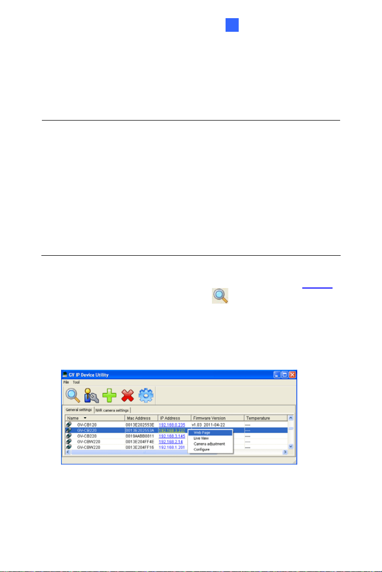
1. Download and install GV-IP Device Utility from the company website
2. On the GV-IP Utility window, click the
button to search for the IP
devices connected in the same LAN. Click the
Name or Mac Address
column to sort.
3. Find the camera with its Mac Address, click on its IP address and
select Web Page.
Figure 5-1
59
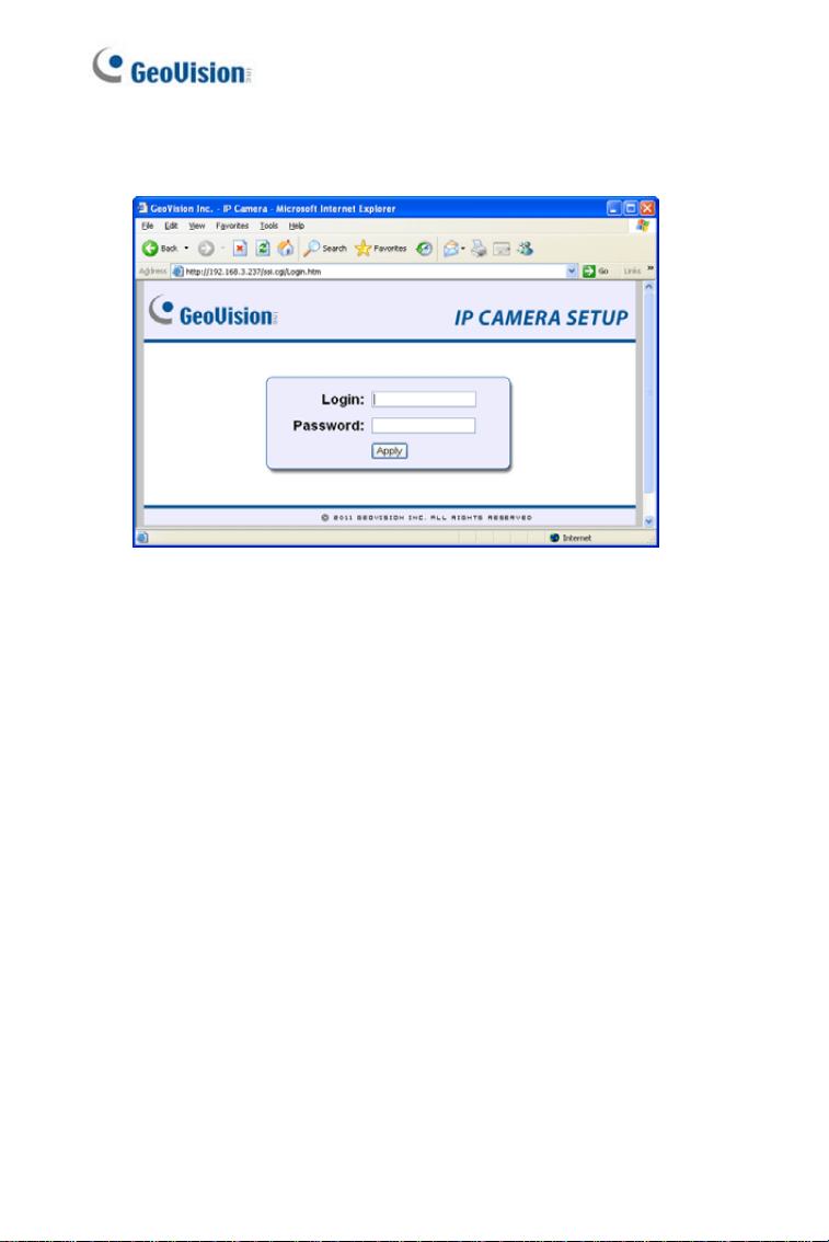
4. The login page appears.
Figure 5-2
5. Type the default ID and password admin and click Apply to log in.
60
Accessing the Camera
5
5.2.2 Configuring the IP Address
Follow the steps below to configure the IP address.
1. Open your Web browser, and type the default IP address
http://192.168.0.10.
2. In both Login and Password fields, type the default value
admin. Click
Apply.
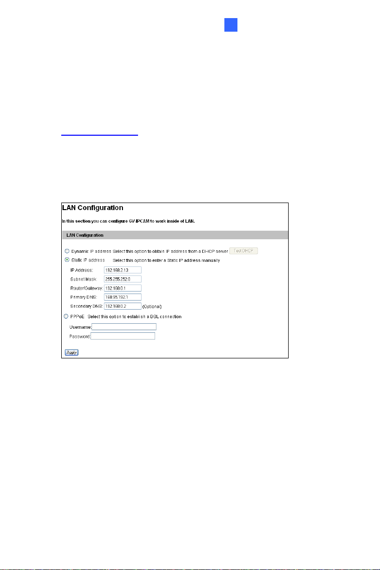
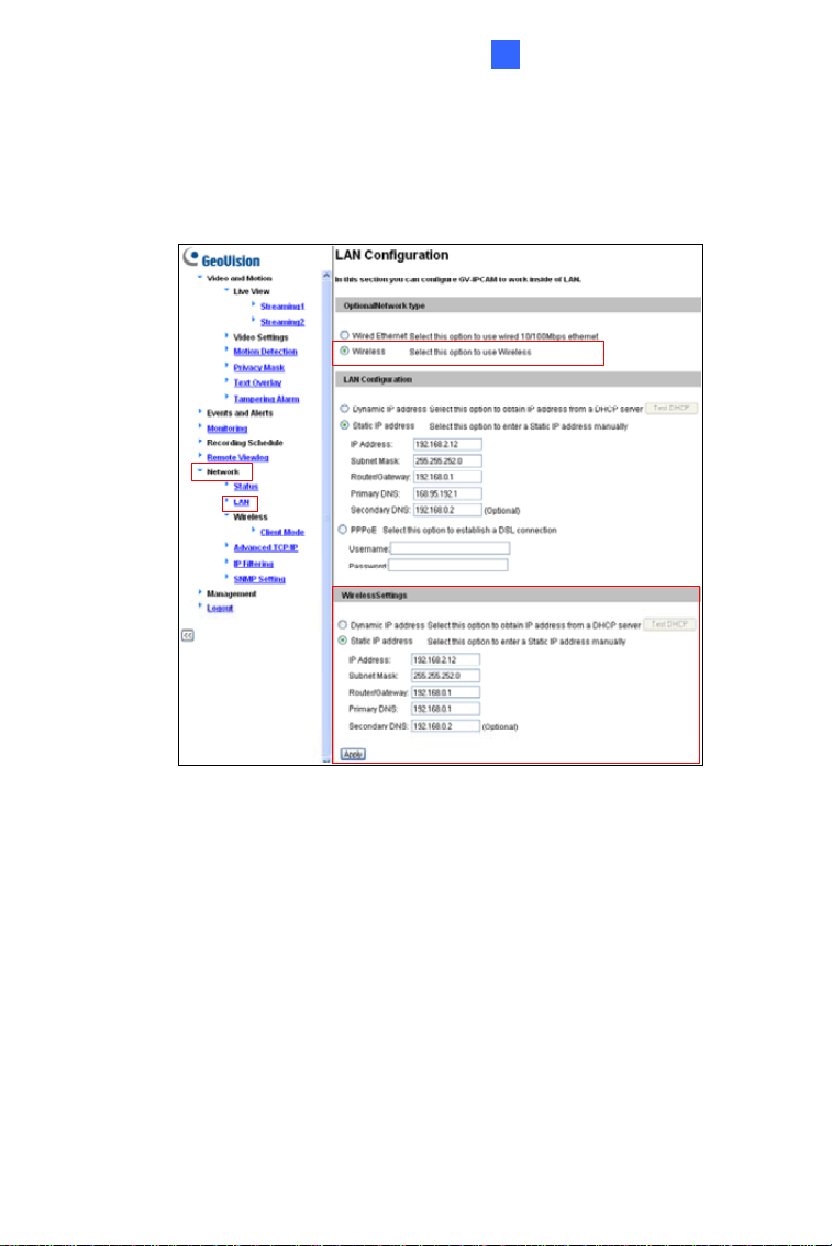
3. In the left menu, select
Network and then LAN to begin the network
settings.
Figure 5-3
4. Select Static IP address, Dynamic IP address or PPPoE and type
the required network information.
5. Click
Apply. The camera is now accessible by entering the assigned
IP address on the Web browser.
6. To enable the updating of images in Microsoft Internet Explorer, you
must set your browser to allow ActiveX Controls and perform a one-
time installation of GeoVision’s ActiveX component onto your
computer.
61

Important:
1. If
Dynamic IP Address or PPPoE is enabled, you need to know
which IP address the camera will get from DHCP server or ISP
to log in. If your camera is installed in the LAN, use the GV-IP
Device Utility to look up its current dynamic IP address. See
5.2.1 Checking the Dynamic IP Address in the Quick Start
Guide. If your camera uses a public dynamic IP address via
PPPoE, use the dynamic DNS Service to obtain a domain name
that is linked to the camera’s changing IP address first. For
details, see LAN Configuration and Advanced TCP/IP sections,
Administrator Mode Chapter in the GV-IPCAM Firmware
Manual.
2. If
Dynamic IP Address or PPPoE is enabled and you cannot
access the camera, you may have to reset the camera to its
factory default and then perform the network settings again. To
restore factory settings, see 1.6, 2.6, 3.5, 4.5. Loading Factory
Default.
62
Accessing the Camera
5
5.2.3 Configuring the Wireless Connection
You may create wireless connection to the Internet for GV-BX1200 series /
1500 series / 2400 series / 2700 series / 3400 series / 5300.
1. To set up the wireless LAN for the first time, power on and connect a
standard network cable to the camera.
2. An IP address will be automatically assigned to the camera. Use GV
IP Device Utility to search for the device. For details, see 5.2.1
Checking the Dynamic IP Address.
3. Configure the wireless settings.
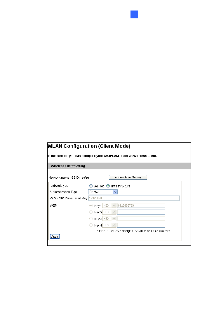
A. On the Web interface, select
Network, select Wireless and
Client Mode. This dialog box appears.
Figure 5-4
B. Type the Network Name (SSID) or click the
Access Point
Survey
button to search and select for the available Access
Points/wireless stations.
C. Select
Ad-Hoc or Infrastructure for the Network type.
63

D. Select the Authentication Type using the drop-down list. You
can also obtain this information by clicking the
Access Point
Survey
button.
E. Type the
WPA-PSK Pre-shared Key or WEP depending on the
encryption setting for the Access Point.
F. Click
Apply to save the configuration.
Note:
1. Your encryption settings must match those used by the Access
Points or wireless stations with which you want to associate.
2. When
Ad Hoc is used, only WEP encryption is supported.
3. When you lose the wireless access, you can still access the unit
by connecting it to a LAN and using the GV IP Device Utility to
search for the device.
64
Accessing the Camera
5
4. Enable wireless LAN.
A. On the Web interface, select
Network and LAN. This page
appears.
Figure 5-5
B. Select
Wireless for Optional Network Type.
C. To use a dynamic IP address assigned by the DHCP server,
select
Dynamic IP address. To use a fixed IP address, select
Static IP address and type the IP address information.
5. Click
Apply. The camera will start creating a wireless connection to
the access point.
6. Unplug the Ethernet cable.
65
5.3 Adjusting Image Clarity
You can adjust the image clarity using the GV-IP Device Utility. Make sure
that you have connected your GV-IPCAM to the network and install the
GV-IP Device Utility program under the same LAN.
1. Make sure you have downloaded and installed GV-IP Device Utility
from the company website
2. On the GV-IP Utility window, click the
button to search for the IP
devices connected in the same LAN. Click the IP Address of the
camera you desire. A drop-down list appears.
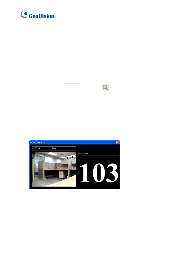
3. Select
Focus Value. The Login dialog box appears.
4. Type the user name and password of the camera selected. The
default is
admin for both user name and password. This window
appears.
Figure 5-6
5. Adjust the Zoom Screw and the Focus Screw of the camera slowly
until the focus value reaches the maximum.
66

Accessing the Camera
67
5
Note:
1. For locations of adjustment screws and rings in each model, see
Locations of Adjustment Screws, section, Getting Started
Chapter, GV-IPCAM Firmware Manual.
2. Do not over tighten the screws. The screws only need to be as
tight as your fingers can get them to be. Do not bother using any
tool to get them tighter. Doing so can damage the structure of
lens.
3. The maximum focus value may vary when the environment
changes.
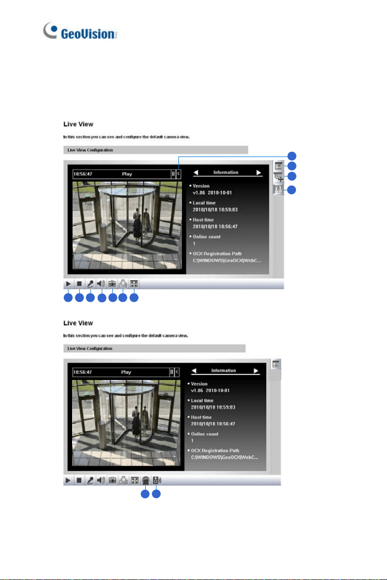
Chapter 6 The Web Interface
1 2 3
4
5 6 7
8
9
10
11
12
13
Figure 6-1
68

The Web Interface
6
No. Name Function
1 Play Plays live video.
2 Stop Stops playing video.
3 Microphone
Broadcasts to the surveillance site from a remote
PC. Note this function is not available for
Ultra
Bullet Camera
and Target Series. For Cube
Camera
and Advanced Cube Camera, click the
Push to talk button (from the pop-up menu) for the
camera to switch between audio transmission and
reception, where only one party can speak at a
time.
4 Speaker
Transfers sounds of the surveillance site to a
remote PC. Note this function is not available for,
Mini Fixed Rugged Dome, Ultra Bullet Camera,
Target Bullet Camera, and Target Mini Fixed
Rugged Dome
.
5 Snapshot Takes a snapshot of live video.
6 File Save Records live video to the local computer.
7 Full Screen
Switches to full screen view. Right-click the image
to see additional options.
8 Control Panel
Displays the camera information, video settings,
audio data rate, I/O device status, images captured
upon alarm, and GPS location of the camera. Also
allows you to adjust image quality and install the
program from the hard drive.
9
Show System
Menu
Brings up these functions: Alarm Notify, Video and
Audio Configuration, Remote Config, Show
Camera Name and Image Enhance.
69

70
No. Name Function
10
PTZ Control
Panel
Enables the PTZ Control Panel or the Visual PTZ.
Note this function is supported by
PTZ Camera
and
PT Camera, and only partially supported by
GV-IP Cameras with motorized varifocal lens.
11 I/O Control
Enables the I/O Control Panel and Visual
Automation. Note this function is not available in
Mini Fixed Dome, Mini Fixed Rugged Dome,
Cube Camera, Advanced Cube Camera and
Target Series.
12 LED Control
Click to turn the Alarm LED on and/or adjust the
brightness sensitivity. Note this function is only
available for
Advanced Cube Camera.
13
Alarm
Speaker
Click to sound the alarm and/or adjust its volume.
To sound the alarm upon motion or tampering
events, see Speaker section, Administrator Mode
Chapter, GV-IPCAM Firmware Manual. Note this
function is only available for
Advanced Cube
Camera
.

Upgrading System Firmware
7
Chapter 7 Upgrading System
Firmware
GeoVision periodically releases updated firmware on the website. The new
firmware can be simply loaded into the GV-IPCAM by using the Web
interface or IP Device Utility.
Before you start
z If you use the IP Device Utility for firmware upgrade, the computer
used to upgrade firmware must be under the same network of the
camera.
z Stop monitoring of the camera.
z Stop all remote connections, such as GV-VMS.
z While the firmware is being updated, the power supply must not be
interrupted.
WARNING: The interruption of power supply during updating causes
not only update failures but also damages to the camera. In this case,
please contact your sales representative and send your device back to
GeoVision for repair.
z Do not turn the power off within 10 minutes after the firmware is
updated.
71
72
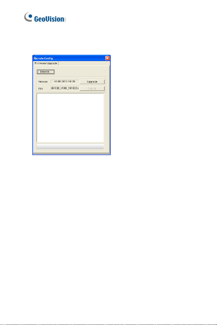
1. In the Live View window, click the Show System Menu button and
select
Remote Config. This dialog box appears.
Figure 7-1
2. Click the Browse button to locate the firmware file (.img) saved at your
local computer.
3. Click the
Upgrade button to start the upgrade.